JP2010055737A - Optical pickup device, focus adjusting method, and optical disk device - Google Patents
Optical pickup device, focus adjusting method, and optical disk device Download PDFInfo
- Publication number
- JP2010055737A JP2010055737A JP2009163888A JP2009163888A JP2010055737A JP 2010055737 A JP2010055737 A JP 2010055737A JP 2009163888 A JP2009163888 A JP 2009163888A JP 2009163888 A JP2009163888 A JP 2009163888A JP 2010055737 A JP2010055737 A JP 2010055737A
- Authority
- JP
- Japan
- Prior art keywords
- light
- signal
- spherical aberration
- optical
- laser
- Prior art date
- Legal status (The legal status is an assumption and is not a legal conclusion. Google has not performed a legal analysis and makes no representation as to the accuracy of the status listed.)
- Granted
Links
Images


Classifications
-
- G—PHYSICS
- G11—INFORMATION STORAGE
- G11B—INFORMATION STORAGE BASED ON RELATIVE MOVEMENT BETWEEN RECORD CARRIER AND TRANSDUCER
- G11B7/00—Recording or reproducing by optical means, e.g. recording using a thermal beam of optical radiation by modifying optical properties or the physical structure, reproducing using an optical beam at lower power by sensing optical properties; Record carriers therefor
- G11B7/12—Heads, e.g. forming of the optical beam spot or modulation of the optical beam
- G11B7/135—Means for guiding the beam from the source to the record carrier or from the record carrier to the detector
- G11B7/1353—Diffractive elements, e.g. holograms or gratings
-
- G—PHYSICS
- G11—INFORMATION STORAGE
- G11B—INFORMATION STORAGE BASED ON RELATIVE MOVEMENT BETWEEN RECORD CARRIER AND TRANSDUCER
- G11B7/00—Recording or reproducing by optical means, e.g. recording using a thermal beam of optical radiation by modifying optical properties or the physical structure, reproducing using an optical beam at lower power by sensing optical properties; Record carriers therefor
- G11B7/08—Disposition or mounting of heads or light sources relatively to record carriers
- G11B7/085—Disposition or mounting of heads or light sources relatively to record carriers with provision for moving the light beam into, or out of, its operative position or across tracks, otherwise than during the transducing operation, e.g. for adjustment or preliminary positioning or track change or selection
- G11B7/08505—Methods for track change, selection or preliminary positioning by moving the head
- G11B7/08511—Methods for track change, selection or preliminary positioning by moving the head with focus pull-in only
-
- G—PHYSICS
- G11—INFORMATION STORAGE
- G11B—INFORMATION STORAGE BASED ON RELATIVE MOVEMENT BETWEEN RECORD CARRIER AND TRANSDUCER
- G11B7/00—Recording or reproducing by optical means, e.g. recording using a thermal beam of optical radiation by modifying optical properties or the physical structure, reproducing using an optical beam at lower power by sensing optical properties; Record carriers therefor
- G11B7/08—Disposition or mounting of heads or light sources relatively to record carriers
- G11B7/09—Disposition or mounting of heads or light sources relatively to record carriers with provision for moving the light beam or focus plane for the purpose of maintaining alignment of the light beam relative to the record carrier during transducing operation, e.g. to compensate for surface irregularities of the latter or for track following
- G11B7/0908—Disposition or mounting of heads or light sources relatively to record carriers with provision for moving the light beam or focus plane for the purpose of maintaining alignment of the light beam relative to the record carrier during transducing operation, e.g. to compensate for surface irregularities of the latter or for track following for focusing only
- G11B7/0909—Disposition or mounting of heads or light sources relatively to record carriers with provision for moving the light beam or focus plane for the purpose of maintaining alignment of the light beam relative to the record carrier during transducing operation, e.g. to compensate for surface irregularities of the latter or for track following for focusing only by astigmatic methods
-
- G—PHYSICS
- G11—INFORMATION STORAGE
- G11B—INFORMATION STORAGE BASED ON RELATIVE MOVEMENT BETWEEN RECORD CARRIER AND TRANSDUCER
- G11B7/00—Recording or reproducing by optical means, e.g. recording using a thermal beam of optical radiation by modifying optical properties or the physical structure, reproducing using an optical beam at lower power by sensing optical properties; Record carriers therefor
- G11B7/08—Disposition or mounting of heads or light sources relatively to record carriers
- G11B7/09—Disposition or mounting of heads or light sources relatively to record carriers with provision for moving the light beam or focus plane for the purpose of maintaining alignment of the light beam relative to the record carrier during transducing operation, e.g. to compensate for surface irregularities of the latter or for track following
- G11B7/0908—Disposition or mounting of heads or light sources relatively to record carriers with provision for moving the light beam or focus plane for the purpose of maintaining alignment of the light beam relative to the record carrier during transducing operation, e.g. to compensate for surface irregularities of the latter or for track following for focusing only
- G11B7/0912—Disposition or mounting of heads or light sources relatively to record carriers with provision for moving the light beam or focus plane for the purpose of maintaining alignment of the light beam relative to the record carrier during transducing operation, e.g. to compensate for surface irregularities of the latter or for track following for focusing only by push-pull method
-
- G—PHYSICS
- G11—INFORMATION STORAGE
- G11B—INFORMATION STORAGE BASED ON RELATIVE MOVEMENT BETWEEN RECORD CARRIER AND TRANSDUCER
- G11B7/00—Recording or reproducing by optical means, e.g. recording using a thermal beam of optical radiation by modifying optical properties or the physical structure, reproducing using an optical beam at lower power by sensing optical properties; Record carriers therefor
- G11B7/08—Disposition or mounting of heads or light sources relatively to record carriers
- G11B7/09—Disposition or mounting of heads or light sources relatively to record carriers with provision for moving the light beam or focus plane for the purpose of maintaining alignment of the light beam relative to the record carrier during transducing operation, e.g. to compensate for surface irregularities of the latter or for track following
- G11B7/0943—Methods and circuits for performing mathematical operations on individual detector segment outputs
-
- G—PHYSICS
- G11—INFORMATION STORAGE
- G11B—INFORMATION STORAGE BASED ON RELATIVE MOVEMENT BETWEEN RECORD CARRIER AND TRANSDUCER
- G11B7/00—Recording or reproducing by optical means, e.g. recording using a thermal beam of optical radiation by modifying optical properties or the physical structure, reproducing using an optical beam at lower power by sensing optical properties; Record carriers therefor
- G11B7/08—Disposition or mounting of heads or light sources relatively to record carriers
- G11B7/09—Disposition or mounting of heads or light sources relatively to record carriers with provision for moving the light beam or focus plane for the purpose of maintaining alignment of the light beam relative to the record carrier during transducing operation, e.g. to compensate for surface irregularities of the latter or for track following
- G11B7/095—Disposition or mounting of heads or light sources relatively to record carriers with provision for moving the light beam or focus plane for the purpose of maintaining alignment of the light beam relative to the record carrier during transducing operation, e.g. to compensate for surface irregularities of the latter or for track following specially adapted for discs, e.g. for compensation of eccentricity or wobble
- G11B7/0956—Disposition or mounting of heads or light sources relatively to record carriers with provision for moving the light beam or focus plane for the purpose of maintaining alignment of the light beam relative to the record carrier during transducing operation, e.g. to compensate for surface irregularities of the latter or for track following specially adapted for discs, e.g. for compensation of eccentricity or wobble to compensate for tilt, skew, warp or inclination of the disc, i.e. maintain the optical axis at right angles to the disc
-
- G—PHYSICS
- G11—INFORMATION STORAGE
- G11B—INFORMATION STORAGE BASED ON RELATIVE MOVEMENT BETWEEN RECORD CARRIER AND TRANSDUCER
- G11B7/00—Recording or reproducing by optical means, e.g. recording using a thermal beam of optical radiation by modifying optical properties or the physical structure, reproducing using an optical beam at lower power by sensing optical properties; Record carriers therefor
- G11B7/12—Heads, e.g. forming of the optical beam spot or modulation of the optical beam
- G11B7/13—Optical detectors therefor
- G11B7/131—Arrangement of detectors in a multiple array
-
- G—PHYSICS
- G11—INFORMATION STORAGE
- G11B—INFORMATION STORAGE BASED ON RELATIVE MOVEMENT BETWEEN RECORD CARRIER AND TRANSDUCER
- G11B7/00—Recording or reproducing by optical means, e.g. recording using a thermal beam of optical radiation by modifying optical properties or the physical structure, reproducing using an optical beam at lower power by sensing optical properties; Record carriers therefor
- G11B7/12—Heads, e.g. forming of the optical beam spot or modulation of the optical beam
- G11B7/13—Optical detectors therefor
- G11B7/133—Shape of individual detector elements
-
- G—PHYSICS
- G11—INFORMATION STORAGE
- G11B—INFORMATION STORAGE BASED ON RELATIVE MOVEMENT BETWEEN RECORD CARRIER AND TRANSDUCER
- G11B7/00—Recording or reproducing by optical means, e.g. recording using a thermal beam of optical radiation by modifying optical properties or the physical structure, reproducing using an optical beam at lower power by sensing optical properties; Record carriers therefor
- G11B7/12—Heads, e.g. forming of the optical beam spot or modulation of the optical beam
- G11B7/135—Means for guiding the beam from the source to the record carrier or from the record carrier to the detector
- G11B7/1381—Non-lens elements for altering the properties of the beam, e.g. knife edges, slits, filters or stops
-
- G—PHYSICS
- G11—INFORMATION STORAGE
- G11B—INFORMATION STORAGE BASED ON RELATIVE MOVEMENT BETWEEN RECORD CARRIER AND TRANSDUCER
- G11B7/00—Recording or reproducing by optical means, e.g. recording using a thermal beam of optical radiation by modifying optical properties or the physical structure, reproducing using an optical beam at lower power by sensing optical properties; Record carriers therefor
- G11B7/12—Heads, e.g. forming of the optical beam spot or modulation of the optical beam
- G11B7/135—Means for guiding the beam from the source to the record carrier or from the record carrier to the detector
- G11B7/1392—Means for controlling the beam wavefront, e.g. for correction of aberration
- G11B7/13925—Means for controlling the beam wavefront, e.g. for correction of aberration active, e.g. controlled by electrical or mechanical means
- G11B7/13927—Means for controlling the beam wavefront, e.g. for correction of aberration active, e.g. controlled by electrical or mechanical means during transducing, e.g. to correct for variation of the spherical aberration due to disc tilt or irregularities in the cover layer thickness
-
- G—PHYSICS
- G11—INFORMATION STORAGE
- G11B—INFORMATION STORAGE BASED ON RELATIVE MOVEMENT BETWEEN RECORD CARRIER AND TRANSDUCER
- G11B7/00—Recording or reproducing by optical means, e.g. recording using a thermal beam of optical radiation by modifying optical properties or the physical structure, reproducing using an optical beam at lower power by sensing optical properties; Record carriers therefor
- G11B2007/0003—Recording, reproducing or erasing systems characterised by the structure or type of the carrier
- G11B2007/0009—Recording, reproducing or erasing systems characterised by the structure or type of the carrier for carriers having data stored in three dimensions, e.g. volume storage
- G11B2007/0013—Recording, reproducing or erasing systems characterised by the structure or type of the carrier for carriers having data stored in three dimensions, e.g. volume storage for carriers having multiple discrete layers
Abstract
Description
本発明は、光ピックアップ装置、焦点調整方法および光ディスク装置に関するものであり、特に、複数の記録層が積層された記録媒体に対して記録/再生を行う際に用いて好適なものである。 The present invention relates to an optical pickup device, a focus adjustment method, and an optical disk device, and is particularly suitable for use in recording / reproduction on a recording medium in which a plurality of recording layers are laminated.
近年、光ディスクの大容量化に伴い、記録層の多層化が進んでいる。一枚のディスク内に複数の記録層を含めることにより、ディスクのデータ容量を顕著に高めることができる。記録層を積層する場合、これまでは片面2層が一般的であったが、最近では、さらに大容量化を進めるために、片面に3層以上の記録層を配することも検討されている。ここで、記録層の積層数を増加させると、ディスクの大容量化を促進できる。しかし、その一方で、記録層間の間隔が狭くなり、層間クロストークによる信号劣化が増大する。 In recent years, with the increase in capacity of optical discs, the number of recording layers has been increasing. By including a plurality of recording layers in one disc, the data capacity of the disc can be remarkably increased. In the case of laminating recording layers, two layers on one side have been common so far, but recently, in order to further increase the capacity, it is also considered to arrange three or more recording layers on one side. . Here, when the number of recording layers is increased, the capacity of the disk can be increased. However, on the other hand, the interval between the recording layers is narrowed, and signal deterioration due to interlayer crosstalk increases.
記録層を多層化すると、記録/再生対象とされる記録層(ターゲット記録層)からの反射光が微弱となる。このため、ターゲット記録層の上下にある記録層から、不要な反射光(迷光)が光検出器に入射すると、検出信号が劣化し、フォーカスサーボおよびトラッキングサーボに悪影響を及ぼす惧れがある。したがって、このように記録層が多数配されている場合には、適正に迷光を除去して、光検出器からの信号を安定化させる必要がある。 When the recording layer is multilayered, the reflected light from the recording layer (target recording layer) to be recorded / reproduced becomes weak. For this reason, when unnecessary reflected light (stray light) is incident on the photodetector from the recording layers above and below the target recording layer, the detection signal may be deteriorated, which may adversely affect the focus servo and tracking servo. Therefore, when a large number of recording layers are arranged in this way, it is necessary to properly remove stray light and stabilize the signal from the photodetector.
以下の特許文献1には、ピンホールを用いて迷光を除去する技術が記載されている。また、特許文献2には、1/2波長板と偏光光学素子を組み合わせることにより迷光を除去する技術が記載されている。
The following
しかしながら、特許文献1の技術によれば、ターゲット記録層から反射されたレーザ光(信号光)の収束位置にピンホールを正確に位置づける必要があるため、ピンホールの位置調整作業が困難であるとの課題がある。位置調整作業を容易にするためピンホールのサイズを大きくすると、迷光がピンホールを通過する割合が増加し、迷光による信号劣化を効果的に抑制できなくなる。
However, according to the technique of
また、特許文献2の技術によれば、迷光を除去するために、1/2波長板と偏光光学素子が2つずつ必要である他、さらに、2つのレンズが必要であるため、部品点数とコストが増加し、また、各部材の配置調整が煩雑であるとの課題がある。また、これらの部材を並べて配置するスペースが必要となり、光学系が大型化するとの課題もある。
In addition, according to the technique of
この他、この種の光ピックアップ装置では、光ディスクのカバー層の厚み変動等によってレーザ光に球面収差が発生する。よって、かかる球面収差の発生を適正に検出して補正する必要がある。 In addition, in this type of optical pickup device, spherical aberration occurs in the laser light due to a variation in the thickness of the cover layer of the optical disk. Therefore, it is necessary to appropriately detect and correct the occurrence of such spherical aberration.
本発明は、このような課題を解消するためになされたものであり、簡素な構成にて効果的に迷光を除去でき、且つ、球面収差を円滑に補正できる光ピックアップ装置、焦点調整方法および光ディスク装置を提供することを目的とする。 The present invention has been made to solve such a problem, and an optical pickup device, a focus adjustment method, and an optical disc that can effectively remove stray light and can smoothly correct spherical aberration with a simple configuration. An object is to provide an apparatus.
本発明の第1の態様に係る光ピックアップ装置は、レーザ光源と、前記レーザ光源から出射されたレーザ光を記録媒体上に収束させる対物レンズと、前記記録媒体によって反射された前記レーザ光に非点収差を導入し、これにより、第1の方向に前記レーザ光が収束することによって生じる第1の焦線位置と、前記第1の方向に垂直な第2の方向に前記レーザ光が収束することによって生じる第2の焦線位置とを前記レーザ光の進行方向に互いに離間させる非点収差素子と、前記記録媒体によって反射された前記レーザ光のうち、異なる4つの光束領域内の光束の進行方向を互いに異ならせ、これら4つの光束領域内の光束を互いに離散させる角度調整素子と、前記離散された各光束を受光して検出信号を出力する光検出器と、前記レーザ光に生じる球面収差を補正する球面収差補正ユニットとを備える。ここで、前記角度調整素子は、前記第1の方向と前記第2の方向にそれぞれ平行で且つ互いにクロスする2つの直線の交点を前記レーザ光軸に整合させたとき、前記2つの直線によって作られる一組の対頂角が並ぶ方向に2つの前記光束領域が配置され、他の一組の対頂角が並ぶ方向に残りの2つの前記光束領域が配置されるよう、前記4つの光束領域を設定する。また、前記光検出器は、前記4つの光束をそれぞれ受光する位置に配された第1のセンサ部と、球面収差による前記光束の強度分布の変化を検出する第2のセンサ部とを有する。 An optical pickup device according to a first aspect of the present invention includes a laser light source, an objective lens for converging the laser light emitted from the laser light source on a recording medium, and the laser light reflected by the recording medium. Astigmatism is introduced, so that the laser beam converges in a first focal line position generated by the convergence of the laser beam in the first direction and in a second direction perpendicular to the first direction. The astigmatism element that separates the second focal line position caused by this in the traveling direction of the laser beam, and the progress of the light beams in four different light beam regions among the laser light reflected by the recording medium An angle adjusting element that makes the directions different from each other and separates the light beams in the four light beam regions from each other, a photodetector that receives the discrete light beams and outputs a detection signal, and the laser light And a spherical aberration correcting unit for correcting a spherical aberration caused. Here, the angle adjusting element is formed by the two straight lines when an intersection of two straight lines parallel to the first direction and the second direction and crossing each other is aligned with the laser optical axis. The four light flux regions are set so that the two light flux regions are arranged in the direction in which the set of vertical angles are arranged, and the remaining two light flux regions are arranged in the direction in which the other set of vertical angles are arranged. In addition, the photodetector includes a first sensor unit disposed at a position where each of the four light beams is received, and a second sensor unit that detects a change in the intensity distribution of the light beam due to spherical aberration.
この態様によれば、4つの光束領域と非点収差の方向(第1および第2の方向)との関係を上記のように設定したため、ターゲット記録層にて反射されたレーザ光(信号光)と、当該ターゲット記録層の上および/若しくは下の記録層から反射されたレーザ光(迷光)とが、光検出器の受光面(オンフォーカス時に信号光スポットが最小錯乱円になる面)上において、互いに重なり合わないようにすることができる。したがって、光検出器により信号光のみを受光することができ、よって、迷光による検出信号の劣化を抑制することができる。また、この作用を、角度調整素子を光路中に配置するのみで実現できる。よって、この態様によれば、簡素な構成にて効果的に迷光による影響を除去することができる。 According to this aspect, since the relationship between the four light beam regions and the astigmatism directions (first and second directions) is set as described above, the laser light (signal light) reflected by the target recording layer And the laser light (stray light) reflected from the recording layer above and / or below the target recording layer on the light receiving surface of the photodetector (the surface where the signal light spot becomes the minimum circle of confusion at the time of on-focus) , So that they do not overlap each other. Therefore, only the signal light can be received by the photodetector, and therefore the detection signal can be prevented from deteriorating due to stray light. Further, this action can be realized only by arranging the angle adjusting element in the optical path. Therefore, according to this aspect, the influence of stray light can be effectively removed with a simple configuration.
加えて、この態様によれば、球面収差による前記光束の強度分布の変化を検出する第2のセンサ部が配されているため、第2のセンサ部からの出力をもとに球面収差の発生具合を検出することができ、この検出結果に基づいて、球面収差の補正を行うことができる。 In addition, according to this aspect, since the second sensor unit for detecting the change in the intensity distribution of the light beam due to the spherical aberration is provided, the generation of the spherical aberration based on the output from the second sensor unit. The condition can be detected, and the spherical aberration can be corrected based on the detection result.
なお、第1の態様において、前記4つの光束領域は、前記2つの直線によって前記レーザ光の光束領域を分割することにより設定され得る。 In the first aspect, the four light beam regions may be set by dividing the light beam region of the laser light by the two straight lines.
さらに、第1の態様において、前記角度調整素子は、離散後の各光束が前記光検出器の受光面上において正方形の異なる4つの頂角の位置にそれぞれ導かれるよう、4つの前記光束領域の進行方向を、前記第1および第2の方向に対し45°の方向で、且つ、所定の角度だけ変化させるよう構成され得る。こうすると、光検出器上におけるセンサパターンの設計を簡易化することができ、また、センサパターン領域をコンパクトにすることができる。 Furthermore, in the first aspect, the angle adjusting element is configured so that the light beams after the separation are guided to four vertex angle positions different from each other on the light receiving surface of the photodetector. The traveling direction may be changed in a direction of 45 ° with respect to the first and second directions and by a predetermined angle. In this way, the design of the sensor pattern on the photodetector can be simplified, and the sensor pattern area can be made compact.
このように、角度調整素子によって離散された各光束が光検出器の受光面上において正方形の異なる4つの頂角の位置にそれぞれ導かれる場合、前記第2のセンサ部は、前記正方形の互いに対向する2つの辺の並び方向に配された2つのセンサと、残り2つの辺の並び方向に配された2つのセンサとを有する構成とされ得る。 As described above, when the light beams dispersed by the angle adjusting element are respectively guided to the positions of the four apex angles having different squares on the light receiving surface of the photodetector, the second sensor unit is opposed to the squares. The two sensors arranged in the direction in which the two sides are arranged and the two sensors arranged in the direction in which the remaining two sides are arranged can be employed.
このとき、光ピックアップ装置は、さらに、前記正方形の互いに対向する2つの辺の並び方向に配された2つの前記センサにおける総受光量に対応する検出信号と、残り2つの辺の並び方向に配された2つの前記センサにおける総受光量に対応する検出信号の差分を演算する第1の演算回路を備える構成とされ得る。 At this time, the optical pickup device further arranges the detection signal corresponding to the total received light amount in the two sensors arranged in the arrangement direction of the two opposite sides of the square and the arrangement direction of the remaining two sides. It can be set as the structure provided with the 1st calculating circuit which calculates the difference of the detection signal corresponding to the total light reception amount in two said sensors.
ここで、前記第2のセンサ部を構成する4つの前記センサの各受光領域は、前記第1のセンサ部に囲まれた領域を、前記正方形の互いに対向する2つの頂点を結ぶ直線と残り2つの頂点を結ぶ直線によって4分割した領域とされ得る。こうすると、各センサからの出力を演算処理することにより、コマ収差の検出信号を生成することができる。 Here, each of the light receiving areas of the four sensors constituting the second sensor unit includes an area surrounded by the first sensor unit, a straight line connecting the two opposite vertices of the square, and the remaining 2 The area can be divided into four by a straight line connecting two vertices. In this way, a coma aberration detection signal can be generated by processing the output from each sensor.
この場合、光ピックアップ装置は、前記正方形の互いに対向する2つの頂点を結ぶ一つの直線によって4つの前記センサを2つのグループに区分したとき、一方のセンサグループにおける総受光量に対応する検出信号と、他方のセンサグループにおける総受光量に対応する検出信号の差分を演算する第2の演算回路を備える構成とされ得る。かかる第2の演算回路による演算結果が、コマ収差の検出信号となる。 In this case, when the optical pickup device divides the four sensors into two groups by one straight line connecting the two opposite vertices of the square, a detection signal corresponding to the total received light amount in one sensor group and The second sensor circuit may be configured to calculate a difference between detection signals corresponding to the total amount of received light in the other sensor group. The calculation result by the second calculation circuit becomes a coma aberration detection signal.
本発明の第2の態様は、照射光の焦点位置を目標面上に位置づける焦点調整方法に関するものである。この焦点調整方法は、前記目標面によって反射された前記照射光に非点収差を導入し、これにより、第1の方向に前記照射光が収束することによって生じる第1の焦線位置と、前記第1の方向に垂直な第2の方向に前記照射光が収束することによって生じる第2の焦線位置とを前記照射光の進行方向に互いに離間させ、前記目標面によって反射された前記照射光のうち、異なる4つの光束領域内の光束の進行方向を互いに異ならせて、これら4つの光束領域内の光束を互いに離散させ、前記離散された各光束を光検出器にて受光する。ここで、前記4つの光束領域は、前記第1の方向と前記第2の方向にそれぞれ平行で且つ互いにクロスする2つの直線の交点を前記照射光の光軸に整合させたとき、前記2つの直線によって作られる一組の対頂角が並ぶ方向に2つの前記光束領域が配置され、他の一組の対頂角が並ぶ方向に残りの2つの前記光束領域が配置されるように設定されている。また、前記光検出器は、前記4つの光束をそれぞれ受光する位置に配された第1のセンサ部と、球面収差による前記光束の強度分布の変化を検出する第2のセンサ部とを有する。こうして、前記第1のセンサ部から出力された検出信号に対し非点収差法に基づく演算処理を行ってフォーカスエラー信号を生成し、前記第2のセンサ部から出力された検出信号に基づいて球面収差を表す信号を生成する。 The second aspect of the present invention relates to a focus adjustment method for positioning the focal position of irradiation light on a target surface. This focus adjustment method introduces astigmatism into the irradiation light reflected by the target surface, thereby causing a first focal line position generated by the convergence of the irradiation light in a first direction; and The irradiation light reflected from the target surface by separating a second focal line position generated by the convergence of the irradiation light in a second direction perpendicular to the first direction in the traveling direction of the irradiation light. Of these, the traveling directions of the light beams in the four different light beam regions are made different from each other, the light beams in these four light beam regions are made discrete from each other, and the discrete light beams are received by the photodetector. Here, when the four light beam regions are aligned with the optical axis of the irradiation light when the intersection of two straight lines that are parallel to and cross each other in the first direction and the second direction, respectively, Two light beam regions are arranged in a direction in which a set of vertical angles formed by straight lines are arranged, and the remaining two light beam regions are arranged in a direction in which another set of vertical angles are arranged. In addition, the photodetector includes a first sensor unit disposed at a position where each of the four light beams is received, and a second sensor unit that detects a change in the intensity distribution of the light beam due to spherical aberration. In this way, a calculation process based on the astigmatism method is performed on the detection signal output from the first sensor unit to generate a focus error signal, and the spherical surface is generated based on the detection signal output from the second sensor unit. A signal representing the aberration is generated.
第2の態様においても、上記第1の態様と同様の効果が奏される。 In the second aspect, the same effect as in the first aspect is achieved.
本発明の第3の態様に係る光ディスク装置は、上記第1の態様およびその具体的態様に係る光ピックアップ装置と、前記光検出器からの信号を演算処理する演算回路と、前記演算回路からの信号に基づいて前記対物レンズおよび前記球面収差補正ユニットを駆動制御するサーボ回路とを備える。 An optical disc device according to a third aspect of the present invention includes an optical pickup device according to the first aspect and a specific aspect thereof, an arithmetic circuit that performs arithmetic processing on a signal from the photodetector, And a servo circuit that drives and controls the objective lens and the spherical aberration correction unit based on a signal.
第3の態様においても、上記第1の態様と同様の効果が奏される。 In the third aspect, the same effect as in the first aspect is achieved.
また、第3の態様に係る光ディスク装置によれば、フォーカスエラー信号とは別に、第2のセンサ部からの信号をもとに球面収差を表す信号が独立して生成される。このため、フォーカスエラー信号を生成するための第1のセンサ部からの出力をもとに、トラッキングエラー信号や再生RF信号を生成すれば、これらの信号をもとに記録動作や再生動作を進めながら、球面収差を表す信号により球面収差の補正動作を実行することができる。 In addition, according to the optical disc device of the third aspect, a signal representing spherical aberration is independently generated based on a signal from the second sensor unit, separately from the focus error signal. For this reason, if the tracking error signal and the reproduction RF signal are generated based on the output from the first sensor unit for generating the focus error signal, the recording operation and the reproduction operation are advanced based on these signals. However, the spherical aberration correction operation can be executed by the signal representing the spherical aberration.
また、第3の態様に係る光ディスク装置によれば、球面収差を表す信号に基づいて球面収差補正ユニットが駆動されるため、たとえば、ジッタや再生RF信号の振幅が最良になるように球面収差補正ユニットを駆動する場合に比べて、より迅速に、球面収差の補正を行うことができる。 In addition, according to the optical disc device according to the third aspect, since the spherical aberration correction unit is driven based on the signal representing the spherical aberration, for example, the spherical aberration correction is performed so that the jitter and the amplitude of the reproduction RF signal are the best. The spherical aberration can be corrected more quickly than when the unit is driven.
以上のとおり、本発明によれば、簡素な構成にて効果的に迷光を除去することができ、且つ、レーザ光に生じる球面収差を円滑に補正できる光ピックアップ装置、焦点調整方法および光ディスク装置を提供することができる。 As described above, according to the present invention, an optical pickup device, a focus adjustment method, and an optical disc device that can effectively remove stray light with a simple configuration and can smoothly correct spherical aberration generated in laser light. Can be provided.
本発明の効果ないし意義は、以下に示す実施の形態の説明により更に明らかとなろう。ただし、以下の実施の形態は、あくまでも、本発明を実施する際の一つの例示であって、本発明は、以下の実施の形態によって何ら制限されるものではない。 The effects and significance of the present invention will become more apparent from the following description of embodiments. However, the following embodiment is merely an example for carrying out the present invention, and the present invention is not limited by the following embodiment.
以下、本発明の実施の形態につき図面を参照して説明する。 Embodiments of the present invention will be described below with reference to the drawings.
<技術的原理>
まず、図1ないし図10を参照して、本実施の形態に適用される技術的原理について説明する。
<Technical principle>
First, the technical principle applied to the present embodiment will be described with reference to FIGS.
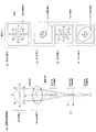
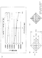
図1(a)は、ターゲット記録層によって反射されたレーザ光(信号光)が、平行光の状態でアナモレンズ等の非点収差素子に入射されたときの信号光と迷光の収束状態を示す図である。なお、“迷光1”は、レーザ光入射面側から見てターゲット記録層よりも一つ奥側にある記録層にて反射されたレーザ光であり、“迷光2”は、ターゲット記録層よりも一つ手前にある記録層にて反射されたレーザ光である。また、同図は、信号光がターゲット記録層にフォーカス合わせされたときの状態を示している。
FIG. 1A is a diagram showing a convergence state of signal light and stray light when laser light (signal light) reflected by a target recording layer is incident on an astigmatism element such as an anamorphic lens in a parallel light state. It is. “Stray light 1” is a laser beam reflected by a recording layer that is one deeper than the target recording layer when viewed from the laser light incident surface side, and “
図示の如く、アナモレンズの作用により、図中の“曲面方向”に信号光が収束することによって面S1に焦線が生じ、さらに、この曲面方向に垂直な図中の“平面方向”に信号光が収束することによって面S2に焦線が生じる。そして、面S1と面S2の間の面S0において、信号光のスポットが最小(最小錯乱円)となる。非点収差法に基づくフォーカス調整では、面S0に光検出器の受光面が置かれる。なお、ここではアナモレンズにおける非点収差作用を簡単に説明するために、便宜上、“曲面方向”と“平面方向”と表現しているが、実際には、互いに異なる位置に焦線を結ぶ作用がアナモレンズによって生じれば良く、図1中の“平面方向”においてアナモレンズが曲率を持っていても良い。 As shown in the figure, the signal light converges in the “curved surface direction” in the figure due to the action of the anamorphic lens, thereby generating a focal line on the surface S1, and further, the signal light in the “plane direction” in the figure perpendicular to the curved surface direction. Converges to produce a focal line on the surface S2. And in the surface S0 between the surface S1 and the surface S2, the spot of the signal light becomes the minimum (minimum circle of confusion). In focus adjustment based on the astigmatism method, the light receiving surface of the photodetector is placed on the surface S0. Here, in order to simply explain the astigmatism action in the anamorphic lens, it is expressed as “curved surface direction” and “planar direction” for the sake of convenience. It may be generated by an anamorphic lens, and the anamorphic lens may have a curvature in the “plane direction” in FIG.
なお、同図(a)に示す如く、迷光1の焦線位置(同図では、非点収差素子による2つの焦線位置の間の範囲を“収束範囲”と示す)は、信号光の焦線位置よりも非点収差素子に接近しており、また、迷光2の焦線位置は、信号光の焦線位置よりも非点収差素子から離れている。
As shown in FIG. 6A, the focal line position of stray light 1 (in the figure, the range between two focal line positions by the astigmatism element is indicated as “convergence range”). It is closer to the astigmatism element than the line position, and the focal line position of the
図1(b)〜(e)は、それぞれ、平行光部分および面S1、S0、S2上における信号光のビーム形状を示す図である。真円で非点収差素子に入射した信号光は、面S1上で楕円となり、面S0上で略真円となった後、面S2上にて再び楕円となる。ここで、面S1上のビーム形状と面S2上のビーム形状は、それぞれの長軸が互いに垂直の関係となっている。 FIGS. 1B to 1E are diagrams showing beam shapes of signal light on the parallel light portion and the surfaces S1, S0, and S2, respectively. The signal light incident on the astigmatism element in a perfect circle becomes an ellipse on the surface S1, becomes a substantially perfect circle on the surface S0, and becomes an ellipse again on the surface S2. Here, the major axis of the beam shape on the surface S1 and the beam shape on the surface S2 are perpendicular to each other.
ここで、同図(a)および(b)のように、平行光部分におけるビームの外周に、反時計方向に8つの位置(位置1〜8:同図では丸囲み数字で表記)を設定すると、位置1〜8を通る光線は、非点収差素子によってそれぞれ収束作用を受ける。なお、位置4と位置8は、曲面方向に平行な直線にて平行光部分のビーム断面を2分割する場合の分割線上に位置しており、位置2と位置6は、平面方向に平行な直線にて平行光部分のビーム断面を2分割する場合の分割線上に位置している。位置1、3、5、7はそれぞれ、位置2、4、6、8によって区分される外周円弧の中間にある。
Here, as shown in FIGS. 9A and 9B, when eight positions (
平行光部分において位置4と位置8を通る光線は、面S1で曲面方向の焦線へと収束された後に面S0へと入射する。このため、これら位置4、8を通る光線は、面S0上において、同図(d)に示す位置4、8を通る。同様に、平行光部分において位置1、3、5、7を通る光線も、面S1にて曲面方向の焦線へと収束された後に面S0へと入射するため、面S0上では、同図(d)に示す位置1、3、5、7を通る。これに対し、平行光部分において位置2、6を通る光線は、面S1で曲面方向の焦線へと収束されずに面S0へと入射する。このため、これら位置2、6を通る光線は、面S0上において、同図(d)に示す位置2、6を通る。
Light rays passing through
図2(b)〜(e)は、それぞれ、平行光部分および面S1、S0、S2上における迷光1のビーム形状と光線通過位置を示す図である。同図(b)に示すように、迷光1の外周にも、上記信号光の場合と同様に8つの位置1〜8を設定すると、これら8つの位置1〜8を通る光線は、曲面方向の焦線および平面方向の焦線の何れかに収束された後に面S0へと入射する。このため、平行光部分において位置1〜8を通る光線は、面S0上において、それぞれ、同図(d)に示す位置1〜8を通る。
FIGS. 2B to 2E are diagrams showing the beam shape and the light beam passage position of the
図3(b)〜(e)は、それぞれ、平行光部分および面S1、S0、S2上における迷光2のビーム形状と光線通過位置を示す図である。同図(b)に示すように、迷光2の外周にも、上記信号光の場合と同様に8つの位置1〜8を設定すると、これら8つの位置1〜8を通る光線は、曲面方向の焦線と平面方向の焦線の何れへも収束されることなく面S0へと入射する。このため、平行光部分において位置1〜8を通る光線は、面S0上において、それぞれ、同図(d)に示す位置1〜8を通る。
FIGS. 3B to 3E are diagrams showing the beam shape and the light beam passage position of the
図4は、以上に説明した平行光部分および面S1、S0、S2上におけるビーム形状と光線の通過位置を、信号光、迷光1および迷光2を対比して示す図である。同図中の(c)の段を対比して分かるとおり、平行光部分において位置1を通過した信号光、迷光1および迷光2の光束は、それぞれ、面S0上において、互いに異なる外周位置を通過する。同様に、平行光部分において位置3,4,5,7,8を通過した信号光、迷光1および迷光2の光束も、面S0において、互いに異なる外周位置を通過する。平行光部分において位置2,6を通過した信号光と迷光2の光束は、面S0において、同じ外周位置を通過する。この場合も、平行光部分において位置2,6を通過した信号光と迷光1の光束は、面S0において、互いに異なる外周位置を通過し、また、平行光部分において位置2、6を通過した迷光1と迷光2の光束は、面S0において、互いに異なる外周位置を通過する。
FIG. 4 is a diagram showing the beam shape and the passage position of the light beam on the parallel light portion and the surfaces S1, S0, and S2 described above in comparison with the signal light, the
次に、以上の現象を考慮して、平行光部分における信号光および迷光1、2の領域分割パターンと、面S0上における信号光および迷光1、2の照射領域との関係について検討する。
Next, considering the above phenomenon, the relationship between the area division pattern of the signal light and
まず、図5(a)に示すように、平行光部分における信号光および迷光1、2を、平面方向と曲面方向に対して45°傾いた2つの直線で分割し、4つの光束領域A〜Dに区分したとする。なお、この分割パターンは、従来の非点収差法に基づく領域分割に対応するものである。
First, as shown in FIG. 5A, the signal light and the
この場合、上述の現象により、光束領域A〜Dの信号光は、面S0上において、同図(b)のように分布する。また、光束領域A〜Dの迷光1および迷光2は、上述の現象により、それぞれ、同図(c)および(d)のように分布する。
In this case, the signal light in the light flux areas A to D is distributed on the surface S0 as shown in FIG. Further, the
ここで、面S0上における信号光と迷光1、2を光束領域毎に取り出すと、各光の分布は、図6(a)ないし(d)のようになる。この場合、各光束領域の信号光には、同じ光束領域の迷光1および迷光2の何れか一方が必ず重なる。このため、各光束領域の信号光を光検出器上のセンサパターンで受光すると、少なくとも、同じ光束領域における迷光1または迷光2が対応するセンサパターンに同時に入射し、これにより検出信号に劣化が生じる。
Here, when the signal light and the
これに対し、図7(a)に示すように、平行光部分における信号光および迷光1、2を、平面方向と曲面方向に平行な2つの直線で分割し、4つの光束領域A〜Dに区分したとする。この場合、上述の現象から、光束領域A〜Dの信号光は、面S0上において、同図(b)のように分布する。また、光束領域A〜Dの迷光1および迷光2は、上述の現象により、それぞれ、同図(c)および(d)のように分布する。
On the other hand, as shown in FIG. 7A, the signal light and the
ここで、面S0上における信号光と迷光1、2を光束領域毎に取り出すと、各光の分布は、図8(a)ないし(d)のようになる。この場合、各光束領域の信号光には、同じ光束領域の迷光1および迷光2の何れも重ならない。このため、各光束領域内の光束(信号光、迷光1、2)を異なる方向に離散させた後に、信号光のみをセンサパターンにて受光するように構成すると、対応するセンサパターンには信号光のみが入射し、迷光の入射を抑止することができる。これにより、迷光による検出信号の劣化を回避することができる。
Here, when the signal light and the
以上のように、信号光および迷光1、2を平面方向と曲面方向に平行な2つの直線で4つの光束領域A〜Dに分割し、これら光束領域A〜Dを通る光を分散させて面S0上において離間させることにより、信号光のみを取り出すことができる。本実施の形態は、この原理を基盤とするものである。
As described above, the signal light and the
図9は、図7(a)に示す4つの光束領域A〜Dを通る光束(信号光、迷光1、2)の進行方向を、それぞれ、異なる方向に、同じ角度だけ変化させたときの、面S0上における信号光と迷光1、2の分布状態を示す図である。ここでは、同図(a)に示すように、光束領域A〜Dを通る光束(信号光、迷光1、2)の進行方向が、それぞれ、方向Da、Db、Dc、Ddに、同じ角度量α(図示せず)だけ変化している。なお、方向Da、Db、Dc、Ddは、平面方向と曲面方向に対して、それぞれ、45°の傾きを持っている。
FIG. 9 shows a case where the traveling directions of the light beams (signal light,
この場合、方向Da、Db、Dc、Ddにおける角度量αを調節することにより、S0平面上において、同図(b)に示すように各光束領域の信号光と迷光1、2を分布させることができる。その結果、図示の如く、信号光のみが存在する信号光領域をS0平面上に設定することができる。この信号光領域に光検出器のセンサパターンを設定することにより、各領域の信号光のみを、対応するセンサパターンにて受光することができる。
In this case, by adjusting the angle amount α in the directions Da, Db, Dc, and Dd, the signal light and the
図10は、フォーカスエラー信号とプッシュプル信号を生成するためのセンサパターンの配置方法を説明する図である。同図(a)および(b)は、従来の非点収差法に基づく光束の分割方法とセンサパターンを示す図であり、同図(c)および(d)は、上述の原理に基づく光束の分割方法とセンサパターンを示す図である。ここで、トラック方向は、平面方向と曲面方向に対して45°の傾きを持っている。なお、同図(a)および(b)には、説明の便宜上、光束が8つの光束領域a〜hに区分されている。また、トラック溝による回折の像が実線で示され、オフフォーカス時のビーム形状が点線によって示されている。 FIG. 10 is a diagram for explaining a sensor pattern arrangement method for generating a focus error signal and a push-pull signal. (A) and (b) are diagrams showing a beam splitting method and a sensor pattern based on the conventional astigmatism method, and (c) and (d) in FIG. It is a figure which shows the division | segmentation method and a sensor pattern. Here, the track direction has an inclination of 45 ° with respect to the plane direction and the curved surface direction. In FIGS. 4A and 4B, for convenience of explanation, the light beam is divided into eight light beam regions a to h. Further, the diffraction image by the track groove is shown by a solid line, and the beam shape at the time of off-focus is shown by a dotted line.
従来の非点収差法では、光検出器のセンサパターンP1〜P4(4分割センサ)が同図(b)のように設定される。この場合、光束領域a〜hの光強度に基づく検出信号成分をA〜Hで表すと、フォーカスエラー信号FEは、FE=(A+B+E+F)−(C+D+G+H)の演算により求まり、プッシュプル信号PPは、PP=(A+B+G+H)−(C+D+E+F)の演算により求まる。 In the conventional astigmatism method, sensor patterns P1 to P4 (four-divided sensors) of the photodetector are set as shown in FIG. In this case, when the detection signal components based on the light intensities of the light flux areas a to h are represented by A to H, the focus error signal FE is obtained by the calculation of FE = (A + B + E + F) − (C + D + G + H), and the push-pull signal PP is PP = (A + B + G + H) − (C + D + E + F).
これに対し、上記図9(b)の分布状態では、上述の如く、信号光領域内に、図10(c)の状態で信号光が分布している。この場合、図10(a)に示す光束領域a〜hを通る信号光の分布を同図(c)の分布に重ねると、同図(d)のようになる。すなわち、同図(a)の光束領域a〜hを通る信号光は、光検出器のセンサパターンが置かれる面S0上では、同図(d)に示す光束領域a〜hへと導かれる。 On the other hand, in the distribution state of FIG. 9B, the signal light is distributed in the state of FIG. 10C in the signal light region as described above. In this case, when the distribution of the signal light passing through the light beam areas a to h shown in FIG. 10A is superimposed on the distribution shown in FIG. 10C, the distribution shown in FIG. That is, the signal light passing through the light flux areas a to h in FIG. 5A is guided to the light flux areas a to h shown in FIG. 4D on the surface S0 on which the sensor pattern of the photodetector is placed.
したがって、同図(d)に示す光束領域a〜hの位置に、同図(d)に重ねて示す如くセンサパターンP11〜P18を設定すれば、同図(b)の場合と同様の演算処理によって、フォーカスエラー信号とプッシュプル信号を生成することができる。すなわち、この場合も、光束領域a〜hの光束を受光するセンサパターンからの検出信号をA〜Hで表すと、同図(b)の場合と同様、フォーカスエラー信号FEは、FE=(A+B+E+F)−(C+D+G+H)の演算により取得でき、また、プッシュプル信号PPは、PP=(A+B+G+H)−(C+D+E+F)の演算により取得することができる。 Therefore, if the sensor patterns P11 to P18 are set at the positions of the light flux areas a to h shown in FIG. 4D, as shown in FIG. 4D, the same calculation process as in FIG. Thus, a focus error signal and a push-pull signal can be generated. That is, also in this case, when the detection signals from the sensor patterns that receive the light beams in the light beam regions a to h are represented by A to H, the focus error signal FE is FE = (A + B + E + F) as in the case of FIG. ) − (C + D + G + H), and the push-pull signal PP can be acquired by the calculation PP = (A + B + G + H) − (C + D + E + F).
以上のように、本原理によれば、平行光部分における信号光および迷光1、2を、図1の平面方向と曲面方向に平行な2つの直線で4つの光束領域A〜Dに分割し、これら光束領域A〜Dを通る光を分散させ、さらに、分散させた後の各光束領域A〜Dにおける信号光を、2分割された受光部によって個別に受光することにより、従来の非点収差法に基づく場合と同様の演算処理にて、フォーカスエラー信号とプッシュプル信号を生成することができる。
As described above, according to the present principle, the signal light and the
次に、本原理を適用した場合の球面収差の影響について説明する。 Next, the influence of spherical aberration when this principle is applied will be described.
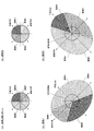
図11(a)、(b)、(c)は、光検出面上における信号光に生じる球面収差の影響をシミュレーションにより求めたシミュレーション結果である。各シミュレーション結果は、ディスク入射面からターゲット記録層までの距離が異なる場合の光検出面上における信号光の強度分布を求めたものである。何れのシミュレーション結果においても、レーザ光はターゲット記録層に対してオンフォーカス状態にある。 FIGS. 11A, 11B, and 11C are simulation results obtained by simulating the influence of spherical aberration generated in the signal light on the light detection surface. Each simulation result is obtained by calculating the intensity distribution of the signal light on the light detection surface when the distance from the disk incident surface to the target recording layer is different. In any simulation result, the laser beam is in an on-focus state with respect to the target recording layer.
同図(b)は、ディスク入射面(ブルーレイディスクを想定)からターゲット記録層までの距離が適正であるときの信号光の状態であり、同図(a)および(c)は、それぞれ、ディスク入射面からターゲット記録層までの距離が適正値からずれた場合の信号光の状態である。 FIG. 4B shows the state of signal light when the distance from the disc incident surface (assuming a Blu-ray disc) to the target recording layer is appropriate. FIGS. This is a state of signal light when the distance from the incident surface to the target recording layer is deviated from an appropriate value.
なお、同図(a)、(b)、(c)では、黒に近いほど光の強度が高くなっている。また、同図(a)は、ディスク入射面からターゲット記録層までの距離が、同図(b)の適正状態から5μm増加して3次球面収差の大きさが50mλrmsであるときのシミュレーション結果であり、同図(c)は、ディスク入射面からターゲット記録層までの距離が、同図(b)の適正状態から5μm減少して3次球面収差の大きさが50mλrmsであるときのシミュレーション結果である。 In addition, in the same figure (a), (b), (c), the intensity | strength of light is so high that it is near black. FIG. 10A shows a simulation result when the distance from the disk incident surface to the target recording layer is increased by 5 μm from the appropriate state of FIG. 10B and the magnitude of the third-order spherical aberration is 50 mλrms. FIG. 6C shows a simulation result when the distance from the disc incident surface to the target recording layer is reduced by 5 μm from the appropriate state of FIG. 5B and the magnitude of the third-order spherical aberration is 50 mλrms. is there.
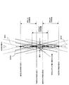
図12は、図11(c)のシミュレーションに用いた光学系を示す図である。図中、10は、波長405nmのレーザ光を出射する半導体レーザ、11は、半導体レーザ10から出射されたレーザ光を略全反射する偏光ビームスプリッタ、12はレーザ光を平行光に変換するコリメートレンズ、13はコリメートレンズ12側から入射されるレーザ光(直線偏光)を円偏光に変換する1/4波長板、14はレーザ光をディスク上に収束させる対物レンズ、15は偏光ビームスプリッタ11を透過したディスクからの反射光に非点収差を導入する検出レンズ、16は、上記図9(a)を参照して説明した作用をレーザ光に付与する角度調整素子、17は光検出器である。
FIG. 12 is a diagram showing an optical system used in the simulation of FIG. In the figure, 10 is a semiconductor laser that emits laser light having a wavelength of 405 nm, 11 is a polarization beam splitter that substantially totally reflects the laser light emitted from the
角度調整素子は、上記図9(a)を参照して説明したように、4つの光束領域A〜Dを通過するレーザ光を互いに分離させて、光検出面上で、図9(b)に示すように各光束領域を通過したレーザ光を分布させる作用を有する。なお、本シミュレーションでは、ターゲット記録層の前後に記録層が一つずつ存在すると仮定されている。なお、ターゲット記録層と前後の記録層との間隔は、それぞれ10μmとされている。 As described with reference to FIG. 9A, the angle adjusting element separates the laser beams passing through the four light flux regions A to D from each other, and on the light detection surface, as shown in FIG. 9B. As shown, the laser beam that has passed through each light flux region is distributed. In this simulation, it is assumed that one recording layer exists before and after the target recording layer. Note that the distance between the target recording layer and the front and rear recording layers is 10 μm.
本光学系の設計条件は、以下の通りである。
(1)往路倍率:10倍
(2)復路倍率:18倍
(3)角度調整素子16によって付与される分光角度:1.9度
(4)角度調整素子16の分光面と光検出器17の検出面の間の光路長:3mm
(5)角度調整素子16を配さないときの光検出面上におけるスポット径:60μm
(6)角度調整素子16を配したときの光検出面上における各信号光(光束領域A〜Dをそれぞれ通過)の変位距離:100μm
The design conditions of this optical system are as follows.
(1) Forward magnification: 10 times (2) Return magnification: 18 times (3) Spectral angle given by the angle adjustment element 16: 1.9 degrees (4) Spectral surface of the
(5) Spot diameter on the light detection surface when the
(6) Displacement distance of each signal light (passing each of the light flux areas A to D) on the light detection surface when the
なお、往路倍率とは、対物レンズの焦点距離に対するコリメートレンズの焦点距離の比であり、復路倍率とは、対物レンズの焦点距離に対するコリメートレンズと検出レンズの合成焦点距離の比のことである。本光学系では、ディスクによって反射されたレーザ光(信号光)は、角度調整素子16を除去すると検出面上において最小錯乱円となる。上記(5)のスポット径とは、この最小錯乱円の径のことである。また、上記(6)の変位距離とは、角度調整素子16を除去したときの検出面上における信号光の光軸中心と、角度調整素子16を配したときの各信号光の頂点位置(図8に示す扇型が直角となる頂点の位置)との間の距離のことである。
The forward magnification is a ratio of the focal length of the collimating lens to the focal length of the objective lens, and the backward magnification is a ratio of the combined focal length of the collimating lens and the detection lens to the focal length of the objective lens. In the present optical system, the laser light (signal light) reflected by the disk becomes a minimum circle of confusion on the detection surface when the
なお、図11(a)、(b)および(c)には、ピーク強度の1/200以上で1/100以下の範囲の信号光がグレーでプロットされており、それ以上の強度の信号光は黒でプロットされている。 In FIGS. 11A, 11B, and 11C, signal light in a range of 1/200 or more and 1/100 or less of the peak intensity is plotted in gray. Is plotted in black.
図11(b)を参照して、球面収差が発生していない場合、光検出面上における4つの信号光SL、SR、SU、SBの強度は互いに等しくなり、また、光検出面上における信号光の強度分布は、同図の左右方向および上下方向においてバランスがとれた状態となっている。この場合、同図に示すように、信号光領域内の上下左右に対称な位置に受光領域A1〜A4を設定すると、受光領域A1〜A4における信号光の受光量は互いに等しくなる。よって、受光領域A1〜A4にそれぞれセンサを配置し、各センサからの出力信号をSA1〜SA4とすると、(SA1+SA3)−(SA2+SA4)=0となる。 Referring to FIG. 11B, when no spherical aberration occurs, the intensity of the four signal lights SL, SR, SU, and SB on the light detection surface are equal to each other, and the signals on the light detection surface are the same. The light intensity distribution is in a balanced state in the horizontal direction and the vertical direction in FIG. In this case, as shown in the figure, when the light receiving areas A1 to A4 are set at symmetrical positions in the signal light area in the vertical and horizontal directions, the received light amounts of the signal lights in the light receiving areas A1 to A4 are equal to each other. Therefore, when sensors are arranged in the light receiving areas A1 to A4 and output signals from the sensors are SA1 to SA4, (SA1 + SA3) − (SA2 + SA4) = 0.
次に、図11(a)を参照して、ディスク入射面からターゲット記録層までの距離が同図(b)の適正値から5μm増加して球面収差が発生した場合には、信号光の強度分布が同図(b)の状態から同図(a)中の矢印方向に偏り、その結果、受光領域A2,A4よりも受光領域A1,A3における信号光の受光量が増加する。よって、受光領域A1〜A4にそれぞれセンサを配置し、各センサからの出力信号をSA1〜SA4とすると、(SA1+SA3)−(SA2+SA4)>0となる。 Next, referring to FIG. 11A, when spherical aberration occurs when the distance from the disk incident surface to the target recording layer is increased by 5 μm from the appropriate value in FIG. The distribution is deviated from the state shown in FIG. 5B in the direction of the arrow in FIG. 5A, and as a result, the amount of signal light received in the light receiving areas A1 and A3 is larger than the light receiving areas A2 and A4. Therefore, if sensors are arranged in the light receiving areas A1 to A4 and output signals from the sensors are SA1 to SA4, (SA1 + SA3) − (SA2 + SA4)> 0.
また、図11(c)を参照して、ディスク入射面からターゲット記録層までの距離が同図(b)の適正値から5μm減少して球面収差が発生した場合には、信号光の強度分布が同図(b)の状態から同図(c)中の矢印方向に偏り、その結果、受光領域A1,A3よりも受光領域A2,A4における信号光の受光量が増加する。よって、受光領域A1〜A4にそれぞれセンサを配置し、各センサからの出力信号をSA1〜SA4とすると、(SA1+SA3)−(SA2+SA4)<0となる。 Referring to FIG. 11C, when spherical aberration occurs when the distance from the disk incident surface to the target recording layer is reduced by 5 μm from the appropriate value in FIG. Is deviated from the state of FIG. 5B in the direction of the arrow in FIG. 5C, and as a result, the amount of signal light received in the light receiving areas A2 and A4 is increased as compared with the light receiving areas A1 and A3. Therefore, when sensors are arranged in the light receiving areas A1 to A4 and output signals from the sensors are SA1 to SA4, (SA1 + SA3) − (SA2 + SA4) <0.
以上のように、信号光領域内の上下左右に対称な位置に受光領域A1〜A4を設定し、これら受光領域A1〜A4にセンサを配置すると、これらセンサからの出力信号SA1〜SA4について(SA1+SA3)−(SA2+SA4)を演算することにより、球面収差の方向と大きさを検出することができる。 As described above, when the light receiving areas A1 to A4 are set at symmetrical positions in the signal light area in the vertical and horizontal directions and the sensors are arranged in the light receiving areas A1 to A4, the output signals SA1 to SA4 from these sensors (SA1 + SA3). ) − (SA2 + SA4) can be calculated to detect the direction and magnitude of the spherical aberration.
図13(a)は、上記シミュレーション条件において、ディスク入射面からターゲット記録層までの距離を適正値から変化させたときの、信号光の受光量の変化をシミュレーションしたシミュレーション結果である。なお、同図の縦軸は、上記光検出器17の信号検出面上における信号光の受光量である。
FIG. 13A shows a simulation result simulating a change in the amount of received signal light when the distance from the disk incident surface to the target recording layer is changed from an appropriate value under the simulation conditions. In addition, the vertical axis | shaft of the figure is the received light quantity of the signal light on the signal detection surface of the said
このシミュレーションでは、上記光検出器17の信号検出面上に、同図(b)の寸法を有するセンサパターンを配置し、このうち中央の4つのセンサSa1〜Sa4(同図(c)参照)にて受光された信号光の受光量(便宜上、Sa1〜Sa4における受光量をSa1〜Sa4と表す)について、Sa1+Sa3、Sa2+Sa4を演算したときの演算結果が示され、併せて、球面収差の大きさ(SA)を示すパラメータ値として、SA=(Sa1+Sa3)−(Sa2+Sa4)の演算結果が示されている。なお、センサSa1〜Sa4は、それぞれ、上記図11における受光領域A1〜A4に配置されている。
In this simulation, a sensor pattern having the dimensions shown in FIG. 4B is arranged on the signal detection surface of the
このシミュレーション結果からも分かるとおり、上述のように、信号光領域内の左右対称な位置に受光領域A1〜A4を設定し、これら受光領域A1〜A4に、それぞれ、センサSa1〜Sa4を配置すると、センサSa1,Sa3からの出力信号の加算値とセンサSa2,Sa4からの出力信号の加算値との差分から、球面収差の方向および大きさを検出することができる。 As can be seen from the simulation results, as described above, when the light receiving areas A1 to A4 are set at left and right symmetrical positions in the signal light area, and the sensors Sa1 to Sa4 are arranged in the light receiving areas A1 to A4, respectively, The direction and magnitude of the spherical aberration can be detected from the difference between the added value of the output signals from the sensors Sa1 and Sa3 and the added value of the output signals from the sensors Sa2 and Sa4.
<実施例>
以下、上記原理に基づく実施例について説明する。
<Example>
Hereinafter, embodiments based on the above principle will be described.
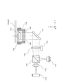
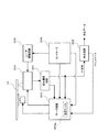
図14に、本実施例に係る光ピックアップ装置の光学系を示す。なお、同図には、便宜上、関連する回路構成が併せて図示されている。また、同図中のディスクには、複数の記録層が積層して配置されている。 FIG. 14 shows an optical system of the optical pickup device according to the present embodiment. In the drawing, related circuit configurations are also shown for convenience. In addition, a plurality of recording layers are stacked on the disk in FIG.
図示の如く、光ピックアップ装置の光学系は、半導体レーザ101と、偏光ビームスプリッタ102と、コリメートレンズ103と、レンズアクチュエータ104と、立ち上げミラー105と、1/4波長板106と、対物レンズ107と、ホルダ108と、対物レンズアクチュエータ109と、検出レンズ110と、角度調整素子111と、光検出器112を備えている。
As shown in the figure, the optical system of the optical pickup apparatus includes a
半導体レーザ101は、所定波長のレーザ光を出射する。偏光ビームスプリッタ102は、半導体レーザ101から入射されるレーザ光(S偏光)を略全反射するとともに、コリメートレンズ103側から入射されるレーザ光(P偏光)を略全透過する。コリメートレンズ103は、偏光ビームスプリッタ102側から入射されるレーザ光を平行光に変換する。
The
レンズアクチュエータ104は、サーボ回路203から入力されるサーボ信号に応じてコリメートレンズ103を光軸方向に変位させる。これにより、レーザ光に生じる球面収差が補正される。立ち上げミラー105は、コリメートレンズ103側から入射されたレーザ光を対物レンズ107に向かう方向に反射する。
The
1/4波長板106は、ディスクへと向かうレーザ光を円偏光に変換するとともに、ディスクからの反射光をディスクへ向かう際の偏光方向に直交する直線偏光に変換する。これにより、ディスクによって反射されたレーザ光は、偏光ビームスプリッタ102を透過する。
The quarter-
対物レンズ107は、レーザ光をディスク内のターゲット記録層に適正に収束できるよう設計されている。ホルダ108は、1/4波長板106と対物レンズ107を一体的に保持する。対物レンズアクチュエータ109は、従来周知の電磁駆動回路によって構成され、当該回路のうち、フォーカスコイル等のコイル部がホルダ108に装着されている。
The
検出レンズ110は、ディスクからの反射光に非点収差を導入する。すなわち、検出レンズ110は、図1の非点収差素子に相当する。
The
角度調整素子111は、検出レンズ110側から入射されたレーザ光の進行方向を、図9を参照して述べた如く変化させる。すなわち、角度調整素子111は、入射されたレーザ光のうち、図9の光束領域A〜Dを通過する光束の進行方向を、それぞれ、方向Da〜Ddに、同じ角度量αだけ変化させる。なお、角度量αは、面S0上における信号光と迷光1、2の分布状態が、図9(b)の分布状態となるように設定されている。
The
光検出器112は、図15(a)に示すセンサパターンを有する。光検出器112は、このセンサパターンが図1の面S0の位置に位置づけられるように配置される。光検出器112には、図10(d)に示す8個のセンサP11〜P18が配されており、これらが、各々、図10(d)の光束領域a〜hを通る光束を受光する。また、光検出器112には、8個のセンサP11〜P18の内側に4個のセンサSa1〜Sa4が配され、これらセンサSa1〜Sa4からの出力信号を、上記図13を参照して説明したように演算処理することにより、球面収差の大きさと方向を示す信号を生成可能となっている。
The
なお、4個のセンサSa1〜Sa4は、図15(b)のように、三角形の輪郭を有するよう構成され得る。この場合も、図11(a)および(c)を参照して分かるとおり、球面収差に基づく信号光の偏りを4個のセンサSa1〜Sa4からの出力信号をもとに検出することができる。すなわち、この場合も、上述の如く、センサSa1〜Sa4からの出力信号について(Sa1+Sa3)−(Sa2+Sa4)の演算を行うことにより、球面収差の大きさと方向を示す信号を生成することができる。 The four sensors Sa1 to Sa4 can be configured to have a triangular outline as shown in FIG. Also in this case, as can be seen with reference to FIGS. 11A and 11C, the deviation of the signal light based on the spherical aberration can be detected based on the output signals from the four sensors Sa1 to Sa4. That is, also in this case, as described above, a signal indicating the magnitude and direction of the spherical aberration can be generated by calculating (Sa1 + Sa3) − (Sa2 + Sa4) for the output signals from the sensors Sa1 to Sa4.
図14に戻り、信号演算回路201は、光検出器112の8個のセンサP11〜P18から出力された検出信号を、図10(d)を参照して述べた如く演算処理し、フォーカスエラー信号とプッシュプル信号を生成する。また、信号演算回路201は、これら8個のセンサP11〜P18から出力された検出信号を加算して再生RF信号を生成する。さらに、信号演算回路201は、光検出器112の4個のセンサSa1〜Sa4から出力された検出信号を、図13を参照して述べた如く演算処理し、球面収差の大きさと方向を示す信号(以下、「球面収差信号」という)を生成する。生成されたフォーカスエラー信号、プッシュプル信号および球面収差信号はサーボ回路203に送られ、再生RF信号は再生回路202に送られる。
Returning to FIG. 14, the signal
再生回路202は、信号演算回路201から入力された再生RF信号を復調して再生データを生成する。サーボ回路203は、信号演算回路201から入力されたプッシュプル信号とフォーカスエラー信号からトラッキングサーボ信号とフォーカスサーボ信号を生成し、これらを対物レンズアクチュエータ109に出力する。また、サーボ回路203は、信号演算回路201から入力された球面収差信号から球面収差を補正するためのサーボ信号を生成し、これをレンズアクチュエータ104に出力する。
The
図16は、角度調整素子111の構成例を示す図である。同図(a)は、回折パターンを有するホログラム素子によって角度調整素子111を構成する場合の構成例を示し、同図(b)および(c)は、多面プリズムによって角度調整素子111を構成する場合の構成例を示している。
FIG. 16 is a diagram illustrating a configuration example of the
まず、同図(a)の構成例において、角度調整素子111は、正方形形状の透明板にて形成され、光入射面にホログラムパターンが形成されている。光入射面は、図示の如く、4つのホログラム領域111a〜111dに区分されている。これらホログラム領域111a〜111dに、それぞれ、図9(a)の光束領域A〜Dを通過したレーザ光(信号光、迷光1、2)が入射するよう、角度調整素子111が検出レンズ110の後段に配置される。
First, in the configuration example of FIG. 2A, the
ホログラム領域111a〜111dは、入射されたレーザ光(信号光、迷光1、2)を、それぞれ、方向Va〜Vdに回折させる。方向Va〜Vdは、図9(a)の方向Da〜Ddに一致している。よって、ホログラム領域111a〜111dは、回折により、検出レンズ110から入射されたレーザ光(信号光、迷光1、2)の進行方向を、それぞれ、図9(a)のDa〜Ddの方向に変化させる。各領域における回折角は同じとなっている。
The
ここで、回折角は、ホログラム領域111a〜111dを通過したレーザ光(信号光、迷光1、2)が、図1の面S0において、図9(b)のように分布するよう調整されている。よって、上記の如く、図15(a)のセンサパターンを有する光検出器112の受光面を面S0に配置することにより、上記8個P11〜P18のセンサによって、対応する信号光を適正に受光することができる。
Here, the diffraction angle is adjusted so that the laser light (signal light,
なお、ホログラム領域111a〜111dの回折効率は互いに同じとなっている。ホログラム領域111a〜111dに形成されるホログラムがステップ型である場合、回折効率は、ホログラムパターンのステップ数と1ステップあたりの高さによって調整され、回折角は、ホログラムパターンのピッチによって調整される。よって、この場合には、予め決められた回折次数の回折効率が所期の値となるように、ホログラムパターンのステップ数と1ステップあたりの高さが設定され、さらに、当該回折次数における回折角が図9(b)の分布を与え得るように、ホログラムパターンのピッチが調整される。
The diffraction efficiencies of the
なお、ホログラム領域111a〜111dに形成されるホログラムをブレーズ型とすることも可能である。この場合、ステップ型のホログラムよりも回折効率を高めることができる。
Note that the holograms formed in the
同図(b)の構成例において、角度調整素子111は、光出射面が平坦で、且つ、光入射面が4つの領域において異なる方向に個別に傾斜する透明体によって形成されている。同図(c)は同図(b)を光入射面側から見た図である。図示の如く、角度調整素子111の光入射面には、4つの傾斜面111e〜111hが形成されている。これら傾斜面に入射面側から光線がX軸に平行に入射すると、傾斜面111e〜111hに入射する際の屈折作用によって、光の進行方向が、それぞれ、同図(c)のVe〜Vhの方向に変化する。ここで、傾斜面111e〜111hにおける屈折角は、同じである。
In the configuration example of FIG. 5B, the
同図(b)の角度調整素子111は、傾斜面111e〜111hに、それぞれ、図9(a)の光束領域A〜Dを通過したレーザ光(信号光、迷光1、2)が入射するよう、検出レンズ110の後段に配置される。こうして角度調整素子111が配置されると、傾斜面111e〜111hにおける屈折方向Ve〜Vhが、図9(a)の方向Da〜Ddに一致することとなる。よって、傾斜面111e〜111hは、屈折により、検出レンズ110から入射されたレーザ光(信号光、迷光1、2)の進行方向を、一定角度だけ、それぞれ、図9(a)のDa〜Ddの方向に変化させる。
In the
ここで、各傾斜面における屈折角は、傾斜面111e〜111hを通過したレーザ光(信号光、迷光1、2)が、図1の面S0において、図9(b)のように分布するよう調整されている。よって、面S0に、図15(a)のセンサパターンを有する光検出器112を配置することにより、上記8個のセンサP11〜P18によって、対応する信号光を適正に受光することができる。このような屈折作用は、回折作用に比べて波長依存性が格段に小さいため、光源の波長変化や多波長光源に対する適応性が高い。
Here, the refraction angle at each inclined surface is such that the laser light (signal light,
なお、図16(a)の構成例では、ホログラム領域111a〜111dに、レーザ光の進行方向を一定角度だけ変化させる角度付与の回折作用のみを持たせるようにしたが、角度付与の他、検出レンズ110による非点収差作用をも同時に発揮するホログラムパターンを、ホログラム領域111a〜111dに設定しても良い。また、角度調整素子111の光入射面に上記角度付与のためのホログラムパターンを形成し、非点収差作用を持たせるためのホログラムパターンを角度調整素子111の光出射面に持たせるようにしても良い。同様に、図16(b)の角度調整素子111においても、光出射面に、非点収差を導入するためのレンズ面を形成するようにしても良く、あるいは、傾斜面111e〜111hを曲面形状として、傾斜面111e〜111hに非点収差のレンズ作用を持たせるようにしても良い。こうすると、検出レンズ110を省略することができ、部品点数とコストの削減を図ることができる。
In the configuration example of FIG. 16A, the
以上、本実施例によれば、ディスク内に配された記録層のうちターゲット記録層から反射された信号光と、当該ターゲット記録層の上および下の記録層から反射された迷光1、2とが、光検出器112の受光面(オンフォーカス時に信号光スポットが最小錯乱円になる面S0)上において、互いに重なり合わないようにすることができる。具体的には、受光面(面S0)上における信号光と迷光1、2の分布を、図9(b)の状態にすることができる。したがって、図9(b)の信号光領域に、図15(a)に示すセンサパターンを配置することにより、センサP11〜P18によって、対応する信号光のみを受光することができる。このため、迷光による検出信号の劣化を抑制することができる。また、この効果を、ディスクによって反射されたレーザ光の光路中、すなわち、図14の構成では検出レンズ110と光検出器112の間に、角度調整素子111を配置するのみで達成することができる。したがって、本実施例によれば、簡素な構成にて効果的に迷光による影響を除去することができる。
As described above, according to the present embodiment, the signal light reflected from the target recording layer among the recording layers arranged in the disk, and the
加えて、本実施例によれば、センサP11〜P18の内側に4つのセンサSa1〜Sa4を配するといった簡単な構成により、球面収差の大きさと方向を検出することができる。球面収差の発生要因として、上記したカバー厚誤差以外にもレーザ波長の変動や各レンズの温度変化等が挙げられるが、上記検出方法を用いれば、これら要因によって発生した球面収差についても検出可能である。また、球面収差の補正には、上記したレンズアクチュエータだけでなく、液晶素子や変形ミラー等の波面状態を動的に調整できる波面補正素子も用いることができる。 In addition, according to the present embodiment, the magnitude and direction of spherical aberration can be detected with a simple configuration in which four sensors Sa1 to Sa4 are arranged inside the sensors P11 to P18. In addition to the cover thickness error described above, the spherical aberration can be caused by fluctuations in the laser wavelength, temperature changes of each lens, etc. However, if the above detection method is used, it is possible to detect spherical aberration caused by these factors. is there. For correcting spherical aberration, not only the lens actuator described above but also a wavefront correction element that can dynamically adjust the wavefront state of a liquid crystal element, a deforming mirror, or the like can be used.
なお、上記原理による効果は、図17に示すように、迷光1の平面方向の焦線位置が面S0(信号光のスポットが最小錯乱円となる面)よりも非点収差素子に接近した位置にあり、且つ、迷光2の曲面方向の焦線位置が面S0よりも非点収差素子から離れた位置にあるときに奏され得るものである。すなわち、この関係が満たされていれば、信号光と迷光1、2の分布は上記図8に示す状態となり、面S0において、信号光と迷光1、2が重なり合わないようにすることができる。換言すれば、この関係が満たされる限り、たとえ、信号光の曲面方向の焦線位置よりも迷光1の平面方向の焦線位置が面S0に接近し、あるいは、信号光の平面方向の焦線位置よりも迷光2の曲面方向の焦線位置が面S0に接近したとしても、上記原理に基づく本発明ないし実施例の効果は奏され得る。
As shown in FIG. 17, the effect of the above principle is that the position of the focal line in the plane direction of the
以上、本発明の実施例について説明したが、本発明は、上記実施例に制限されるものではなく、また、本発明の実施形態も上記以外に種々の変更が可能である。 As mentioned above, although the Example of this invention was described, this invention is not restrict | limited to the said Example, Moreover, various changes besides the above are possible for embodiment of this invention.
たとえば、上記実施例では、光束領域A〜Dを通る光束の進行方向を図9(a)の方向Da〜Ddへと変化させるようにしたが、図18(a)に示す如く、ランダムな方向に進行方向を変化させても良く、あるいは、角度量に変化をつけて同じ方向に変化させるようにしても良い。要するに、図8に示す光束領域A〜Dの各信号光領域に、他の光束領域からの迷光領域が掛からないよう、光束領域A〜Dを通る光束を分散させれば良い。こうすると、それぞれの信号光のみを、対応するセンサで受光することができ、迷光の影響を除去することができる。 For example, in the above embodiment, the traveling direction of the light beam passing through the light beam regions A to D is changed to the directions Da to Dd in FIG. 9A. However, as shown in FIG. The direction of travel may be changed, or the angle amount may be changed and changed in the same direction. In short, the light beams passing through the light beam regions A to D may be dispersed so that the signal light regions of the light beam regions A to D shown in FIG. 8 are not covered with stray light regions from other light beam regions. In this way, only each signal light can be received by the corresponding sensor, and the influence of stray light can be eliminated.
なお、このように光束領域A〜Dを通る光束の進行方向を変化させる場合には、これに応じて、球面収差検出用のセンサSa1〜Sa4の配置を適宜調整する必要がある。この場合も、球面収差検出用のセンサSa1〜Sa4は、上記と同様、センサSa1,Sa3からの出力信号の加算値とセンサSa2,Sa4からの出力信号の加算値との差分から、球面収差の方向および大きさを検出できる位置に配置される。 When the traveling direction of the light beam passing through the light beam regions A to D is changed as described above, it is necessary to appropriately adjust the arrangement of the spherical aberration detection sensors Sa1 to Sa4 accordingly. Also in this case, the spherical aberration detection sensors Sa1 to Sa4 are similar to the above in that the spherical aberration is calculated from the difference between the added value of the output signals from the sensors Sa1 and Sa3 and the added value of the output signals from the sensors Sa2 and Sa4. It is arranged at a position where the direction and size can be detected.
また、上記実施例では、レーザ光を図7(a)に示すように均等に4分割して光束領域A〜Dを設定したが、図18(b)のように平面方向の2分割線と曲面方向の2分割線に掛からないように光束領域A〜Dを設定することもでき、また、図18(c)および(d)のように、これら2つの2分割線によって作られる対頂角が並ぶ方向に位置する2つの光束領域のうち、光束領域C、Bの方のみがこれら2つの2分割線に掛からないようにし(同図(c)参照)、あるいは、光束領域A、Dの方のみがこれら2つの2分割線に掛からないようにすることもできる(同図(d)参照)。なお、同図(c)、(d)では、分割線からはみ出した部分の迷光成分が信号光に重畳されるため、上記実施例に比べると、検出信号がやや劣化する。また、光束領域A〜Dの形状が上記実施例に比べて変化しているため、これに応じてセンサの形状を調整する必要がある。 Further, in the above embodiment, the laser beam is equally divided into four as shown in FIG. 7A to set the light flux areas A to D. However, as shown in FIG. The light flux areas A to D can also be set so as not to cover the two-part dividing line in the curved surface direction, and the vertical angles formed by these two parting lines are arranged as shown in FIGS. 18 (c) and 18 (d). Of the two light beam regions positioned in the direction, only the light beam regions C and B are not covered with these two split lines (see FIG. 3C), or only the light beam regions A and D It is also possible to prevent this from being applied to these two dividing lines (see FIG. 4D). In FIGS. 3C and 3D, since the stray light component of the portion protruding from the dividing line is superimposed on the signal light, the detection signal is slightly deteriorated as compared with the above embodiment. Further, since the shapes of the light flux regions A to D are changed as compared with the above-described embodiment, it is necessary to adjust the shape of the sensor accordingly.
また、上記図14の構成では、信号光を一つの光検出器112で受光するようにしたが、たとえば、図19に示すように、角度調整素子111を透過したレーザ光を無偏光ビームスプリッタ(ハーフミラー等)120によって分割し、分割したレーザ光をそれぞれ2つの光検出器121、122にて受光するよう光学系を変更することもできる。この場合、光検出器121には、図10(d)に示すセンサパターン(センサP11〜P18)が配され、光検出器122には、図15(a)または(b)に示す4つのセンサSa1〜Sa4のみからなるセンサパターンが配される。
In the configuration shown in FIG. 14, the signal light is received by the
なお、図19の構成例では、角度調整素子111が無偏光ビームスプリッタ120の前段に配置されているが、角度調整素子111を省略し、光検出器121、122上において図9(b)の分布を生じさせる2つの角度調整素子を、それぞれ、無偏光ビームスプリッタ120と光検出器121の間の光路と無偏光ビームスプリッタ120と光検出器122の間の光路に配するようにしても良い。なお、図19の構成例では、無偏光ビームスプリッタ120を用いてレーザ光の光路を分離させるようにしたが、この他、1/2波長板と偏光ビームスプリッタの組み合わせや、回折格子を用いて光路を分離させることもできる。
In the configuration example of FIG. 19, the
なお、上記図19の構成例では、角度調整素子111を検出レンズ110と無偏光ビームスプリッタ120の間に配置したが、角度調整素子は、対物レンズ107と光検出器112の間の光路中の任意の位置に配置することができる。ただし、対物レンズ107に向かうレーザ光の光路と重なる位置に角度調整素子を配置する場合には、対物レンズ107に向かうレーザ光に角度調整作用を付与しないように角度調整素子を構成する必要がある。たとえば、角度調整素子を図16(a)に示す構成とする場合には、角度調整素子として偏光依存性のホログラム素子を用いる。すなわち、対物レンズ107に向かう際のレーザ光の偏光方向には回折作用を発揮せず、対物レンズ107から戻ってくるレーザ光の偏光方向に回折作用を発揮するようにホログラム素子を構成する。
In the configuration example of FIG. 19, the
図20は、この場合の構成例を示す図である。この構成例では、ホルダ108に、偏光依存性のホログラム素子にて構成された角度調整素子130が装着されている。角度調整素子130は、対物レンズ107に向かう際のレーザ光(S偏光)には回折作用を発揮せず、対物レンズ107から戻ってくるレーザ光(P偏光)に回折作用を発揮する。この場合、光束領域A〜Dに対する角度変更作用は、図16(a)の場合と同様である。ただし、光検出器112の受光面と角度調整素子130との間の光路長が上記実施例に比べて長いため、レーザ光の進行方向を変化させる角度量は、上記実施例よりも小さくなる。
FIG. 20 is a diagram showing a configuration example in this case. In this configuration example, an
この構成例では、角度調整素子130がホルダ108に装着されているため、対物レンズ107がトラッキング方向にずれても、角度調整素子130には、対物レンズ107からの戻り光(ディスクからの反射光)に対して、相対的な中心ずれが生じることがない。よって、トラッキング動作時の光軸ずれによる検出信号の劣化を抑制できる。
In this configuration example, since the
なお、上記実施例のように、センサP11〜P18の内側に、図15(a)に示す4つのセンサSa1〜Sa4を配置すると、これらセンサSa1〜Sa4からの出力信号をもとに、球面収差の他、コマ収差を検出することができる。 If the four sensors Sa1 to Sa4 shown in FIG. 15A are arranged inside the sensors P11 to P18 as in the above embodiment, the spherical aberration is based on the output signals from these sensors Sa1 to Sa4. In addition, coma aberration can be detected.
図21(a−2)、(b−2)、(c−2)は、光検出面上における信号光に生じるコマ収差の影響をシミュレーションにより求めたシミュレーション結果である。同図(b−2)は、同図(b−1)のようにレーザ光軸L0がディスク面(ブルーレイディスクを想定)に直交する場合(コマ収差が発生しない場合)の信号光の状態であり、同図(a−2)および(c−2)は、それぞれ、同図(a−1)および(c−1)のように、ディスクが径方向に傾いてコマ収差が発生した場合の信号光の状態である。 21 (a-2), (b-2), and (c-2) are simulation results obtained by simulating the influence of coma aberration generated in the signal light on the light detection surface. FIG. 6B-2 shows the state of signal light when the laser optical axis L0 is orthogonal to the disc surface (assuming a Blu-ray disc) (when no coma aberration occurs) as shown in FIG. In the same figure, (a-2) and (c-2) are the cases where the disc is tilted in the radial direction and coma occurs as shown in (a-1) and (c-1). This is the state of signal light.
なお、同図(a−2)、(b−2)、(c−2)では、黒に近いほど光の強度が高くなっている。また、同図(a−2)は、同図(b−1)の状態からディスクが反時計方向に0.5度径方向に傾いて3次コマ収差の大きさが30mλrmsであるときのシミュレーション結果であり、同図(c−2)は、同図(b−1)の状態からディスクが時計方向に0.5度径方向に傾いて3次コマ収差の大きさが30mλrmsであるときのシミュレーション結果である。 In addition, in the same figure (a-2), (b-2), (c-2), the intensity | strength of light is so high that it is black. Also, (a-2) in the figure is a simulation when the disk is tilted 0.5 degrees in the counterclockwise direction from the state in (b-1) and the magnitude of the third-order coma aberration is 30 mλrms. (C-2) shows the result when the disc is tilted 0.5 degrees in the clockwise direction from the state shown in (b-1) and the magnitude of the third-order coma aberration is 30 mλrms. It is a simulation result.
同図(a−2)、(b−2)、(c−2)は、上記図12の光学系を用いて行った。なお、本シミュレーションにおいても、ターゲット記録層の前後に記録層が一つずつ存在すると仮定されている。なお、ターゲット記録層と前後の記録層との間隔は、それぞれ10μmとされている。図21(a−2)、(b−2)、(c−2)には、図11の場合と同様、ピーク強度の1/200以上で1/100以下の範囲の信号光がグレーでプロットされており、それ以上の強度の信号光は黒でプロットされている。 (A-2), (b-2), and (c-2) were performed using the optical system shown in FIG. In this simulation, it is assumed that one recording layer exists before and after the target recording layer. Note that the distance between the target recording layer and the front and rear recording layers is 10 μm. In FIG. 21 (a-2), (b-2), and (c-2), as in the case of FIG. 11, signal light in the range of 1/200 to 1/100 of the peak intensity is plotted in gray. The signal light of higher intensity is plotted in black.
図21(b−2)を参照して、ディスクにチルトが発生していない場合、光検出面上における4つの信号光SL、SR、SU、SBの強度は互いに等しくなり、また、光検出面上における信号光の強度分布は、同図の左右方向および上下方向においてバランスがとれた状態となっている。この場合、同図に示すように、信号光領域内の左右対称な位置に受光領域AL、ARを設定すると、受光領域AL、ARにおける信号光の受光量は互いに等しくなる。よって、受光領域AL、ARにそれぞれセンサを配置すると、各センサパターンから出力される信号の差はゼロとなる。 Referring to FIG. 21B-2, when the disc is not tilted, the intensities of the four signal lights SL, SR, SU, and SB on the light detection surface are equal to each other, and the light detection surface The intensity distribution of the signal light above is balanced in the horizontal direction and vertical direction in the figure. In this case, as shown in the figure, when the light receiving areas AL and AR are set at symmetrical positions in the signal light area, the received light amounts of the signal light in the light receiving areas AL and AR are equal to each other. Therefore, when the sensors are arranged in the light receiving areas AL and AR, the difference between the signals output from the sensor patterns becomes zero.
次に、図21(a−2)を参照して、ディスクに反時計方向のチルトが発生した場合、信号光SLよりも信号光SRの強度が高くなり、また、信号光SLのサイドローブよりも信号光SRのサイドローブが大きくなる。この場合、受光領域ALよりも受光領域ARにおける信号光の受光量が大きくなる。よって、受光領域AL、ARにそれぞれセンサを配置し、各センサからの出力信号をSAL、SARとすると、SAL−SAR<0となる。 Next, referring to FIG. 21A-2, when the counterclockwise tilt occurs on the disc, the intensity of the signal light SR becomes higher than that of the signal light SL, and moreover than the side lobe of the signal light SL. However, the side lobe of the signal light SR is increased. In this case, the amount of signal light received in the light receiving area AR is larger than that in the light receiving area AL. Therefore, if sensors are arranged in the light receiving areas AL and AR and the output signals from the sensors are SAL and SAR, SAL-SAR <0.
また、図21(c−2)を参照して、ディスクに時計方向のチルトが発生した場合には、信号光SRよりも信号光SLの強度が高くなり、また、信号光SRのサイドローブよりも信号光SLのサイドローブが大きくなる。この場合には、受光領域ARよりも受光領域ALにおける信号光の受光量が大きくなるため、受光領域AL、ARにそれぞれセンサを配置し、各センサからの出力信号をSAL、SARとすると、SAL−SAR>0となる。 Referring to FIG. 21 (c-2), when a clockwise tilt occurs in the disk, the intensity of the signal light SL is higher than that of the signal light SR, and moreover than the side lobe of the signal light SR. However, the side lobe of the signal light SL is increased. In this case, since the amount of signal light received in the light receiving area AL is larger than that in the light receiving area AR, sensors are arranged in the light receiving areas AL and AR, and the output signals from the sensors are SAL and SAR. -SAR> 0.
以上のように、信号光領域内の左右対称な位置に受光領域AL、ARを設定し、これら受光領域AL、ARにセンサを配置すると、これらセンサからの出力信号の差分から、ディスクチルトの方向と大きさを検出することができる。 As described above, when the light receiving areas AL and AR are set at symmetrical positions in the signal light area and the sensors are arranged in the light receiving areas AL and AR, the disc tilt direction is determined from the difference between the output signals from these sensors. And the size can be detected.
図22(a)は、上記シミュレーション条件において、レーザ光軸L0に対するディスク面の傾き角(ディスクチルト)を変化させたときの、受光領域AL、ARにおける受光量の変化をシミュレーションしたシミュレーション結果である。 FIG. 22A shows a simulation result of simulating changes in the amount of light received in the light receiving areas AL and AR when the tilt angle (disk tilt) of the disk surface with respect to the laser optical axis L0 is changed under the above simulation conditions. .
なお、同図の横軸は、図21(b−1)の状態(レーザ光軸がディスク面に直交する状態)における傾き角(ディスクチルト)をゼロとし、この状態から、たとえば、図21(a−1)のように、ディスク径方向において反時計方向にディスクが傾いたときの傾き角(ディスクチルト)を正としている。また、同図の縦軸は、上記光検出器17の信号検出面上における信号光の受光量である。
Note that the horizontal axis of FIG. 9 indicates that the tilt angle (disc tilt) in the state of FIG. 21B-1 (the laser optical axis is orthogonal to the disc surface) is zero, and from this state, for example, FIG. As in a-1), the tilt angle (disc tilt) when the disc is tilted counterclockwise in the disc radial direction is positive. In addition, the vertical axis in the figure represents the amount of received signal light on the signal detection surface of the
このシミュレーションでは、上記光検出器17の信号検出面上に、同図(b)の寸法を有するセンサパターン(上記図13(b)と同様)を配置し、このうち中央の4つのセンサSa1〜Sa4(図22(c)参照)にて受光された信号光の受光量(上記と同様、便宜上、Sa1〜Sa4における受光量をSa1〜Sa4と表す)について、Sa2+Sa3、Sa1+Sa4を演算したときの演算結果が示され、併せて、コマ収差の大きさ(CM)を示すパラメータ値として、CM=(Sa2+Sa3)−(Sa1+Sa4)の演算結果が示されている。なお、センサSa2、Sa3は、上記図21における受光領域ALに配置され、センサSa1、Sa4は、上記図21における受光領域ARに配置されている。
In this simulation, a sensor pattern (similar to FIG. 13B) having the dimensions shown in FIG. 13B is arranged on the signal detection surface of the
このシミュレーション結果からも分かるとおり、上述のように、信号光領域内の左右対称な位置に受光領域AL、ARを設定し、これら受光領域AL、ARに、それぞれ、センサSa2,Sa3とセンサSa1,Sa4を配置すると、センサSa2,Sa3からの出力信号の加算値とセンサSa1,Sa4からの出力信号の加算値との差分から、コマ収差の方向および大きさ、すなわち、ディスクチルトの方向と大きさを検出することができる。 As can be seen from the simulation results, as described above, the light receiving areas AL and AR are set at symmetrical positions in the signal light area, and the sensors Sa2 and Sa3 and the sensors Sa1 and Sa1, respectively, are set in the light receiving areas AL and AR. When Sa4 is arranged, the coma aberration direction and magnitude, that is, the disc tilt direction and magnitude, from the difference between the added value of the output signals from the sensors Sa2 and Sa3 and the added value of the output signals from the sensors Sa1 and Sa4. Can be detected.
このようにセンサSa1〜Sa4からの出力信号をもとに、球面収差の他、コマ収差をも検出する場合、図14に示す信号演算回路201は、センサSa1〜Sa4からの出力信号について、SA=(Sa1+Sa3)−(Sa2+Sa4)演算の他、CM=(Sa2+Sa3)−(Sa1+Sa4)の演算も行って、ディスクチルトの方向と大きさを検出する。また、サーボ回路203は、信号演算回路201から入力されたチルトエラー信号(CM)をもとにチルトサーボ信号を生成し、これを、対物レンズアクチュエータ109に供給する。
In this way, when detecting coma aberration as well as spherical aberration based on the output signals from the sensors Sa1 to Sa4, the
対物レンズアクチュエータ109は、供給されたチルトサーボ信号に応じて、対物レンズ107をディスク径方向に傾ける。これにより、傾いた対物レンズで生じるコマ収差がディスクの傾きで生じるコマ収差を打ち消して、コマ収差が補正される。なお、この場合には、対物レンズアクチュエータ109が、対物レンズ107を、フォーカス方向およびトラッキング方向の他、チルト方向にも駆動できるよう構成されている必要がある。
The
このように、光検出器112のセンサパターンを図15(a)のように設定すると、球面収差の他、ディスクチルト(コマ収差)をも検出できるようになる。よって、光ピックアップ装置をディスクチルト(コマ収差)にも対応可能とする場合には、光検出器112のセンサパターンを、図15(b)ではなく図15(a)のように設定するのが好ましい。
As described above, when the sensor pattern of the
なお、ここでは、ディスク面がレーザ光軸に対してディスク径方向に傾いた場合(ラジアルチルト)のコマ収差を例に説明したが、本発明は、ディスク面がレーザ光軸に対してトラック接線方向に傾いた場合(タンジェンシャルチルト)のコマ収差についても同様に適用できる。この場合、図21に示す信号光の強度分布は、信号光SUと信号光SBとの間でアンバランスとなる。よって、コマ収差を検出するための2つの受光領域は、図21のように左右に対称な配置(AL、AR)から上下に対称な配置に変更される。なお、センサパターンを図15(a)のように構成すれば、信号Sa1〜Sa4に対する演算により、ラジアルチルトによるコマ収差を表す信号とタンジェンシャルチルトによるコマ収差を表す信号の両方を生成することができる。 Here, the coma aberration in the case where the disk surface is tilted in the disk radial direction with respect to the laser optical axis (radial tilt) has been described as an example. However, in the present invention, the disk surface is track tangent to the laser optical axis. The same applies to coma when tilting in the direction (tangential tilt). In this case, the intensity distribution of the signal light shown in FIG. 21 is unbalanced between the signal light SU and the signal light SB. Accordingly, the two light receiving regions for detecting coma aberration are changed from a symmetrical arrangement (AL, AR) to the left and right as shown in FIG. If the sensor pattern is configured as shown in FIG. 15A, a signal representing the coma due to radial tilt and a signal representing the coma due to tangential tilt can be generated by calculating the signals Sa1 to Sa4. it can.
また、上記では、コマ収差を補正する手段として、対物レンズアクチュエータ109を用いたが、他の手段として、液晶素子等、制御信号に応じてレーザ光の波面状態を動的に調整できる波面補正素子を用いることもできる。コマ収差は、上記ディスクの傾き(チルト)の他、対物レンズや他のレンズ素子の傾き等によっても起こり得る。波面補正素子を用いると、これらの要因によって生じるコマ収差にも円滑に対応することができる。
In the above description, the
<光ディスク装置>
光ディスク装置は、より詳細には、以下のように構成され得る。なお、以下には、複数の記録層を有する光ディスクに対して再生を行う光ディスク装置を例示する。
<Optical disk device>
More specifically, the optical disc apparatus can be configured as follows. In the following, an optical disc apparatus that performs playback on an optical disc having a plurality of recording layers will be exemplified.
図23は、光ディスク装置の要部構成を示す図である。図示の如く、光ディスク装置は、図14に示す信号演算回路201、再生回路202およびサーボ回路203の他に、光ピックアップ装置204と、レーザ駆動回路205と、コントローラ206を備えている。ディスク10は、積層方向に複数の記録層を備える。各記録層には螺旋状にトラックが形成されており、たとえば、トラックを径方向にウォブルさせることによって、アドレス情報が保持されている。
FIG. 23 is a diagram showing a main configuration of the optical disc apparatus. As shown in the figure, the optical disc apparatus includes an
光ピックアップ装置204は、図14に示す光学系を備えている。レーザ駆動回路205は、光ピックアップ装置204内に配された半導体レーザ101をコントローラ206からの指令に応じて駆動する。コントローラ206は、CPUとメモリを備え、メモリに格納されたプログラムに従って各部を制御する。
The
サーボ回路203は、CPUとメモリを備え、メモリに格納されたプログラムに従って各部を制御する。この他、サーボ回路203は、図25に示す回路等を備えている。サーボ回路203は、ディスク10の各記録層と、コリメートレンズ103の設定位置(ステッピングモータのステップ数)とを対応づけたテーブル(設定テーブル203a)を保持している。ここで、設定位置は、対応する記録層にレーザ光を収束させるときに、最も球面収差が抑制され得るとして予め設定されたコリメートレンズ103の位置である。設定テーブル203aは、後述の如く、コリメートレンズ103に対する収差補正を行う際に参照される。
The
サーボ回路203には、再生回路202から、ディスク上の再生位置を示すアドレスデータが入力される。サーボ回路203は、このアドレスデータを参照して、ディスク径方向における再生位置の変化量を判別し、後述の如く、コリメートレンズ103に対するサーボ動作を実行する。
The
図24は、信号演算回路201の構成のうち、上記球面収差に関する信号(球面収差信号)SAと上記コマ収差に関する信号(チルトエラー信号)CMを生成するための回路構成を示す図である。便宜上、同図には、上記図15(a)に示すセンサSa1〜Sa4が示されている。
FIG. 24 is a diagram showing a circuit configuration for generating a signal (spherical aberration signal) SA related to the spherical aberration and a signal (tilt error signal) CM related to the coma aberration, among the configurations of the signal
図示の如く、信号演算回路201は、4つのI/Vアンプ301〜304と、4つの加算回路305〜308と、2つの減算回路309、310を備えている。I/Vアンプ301〜304は、それぞれ、センサSa1〜Sa4からの出力電流信号を、増幅するとともに電圧信号に変換する。加算回路305〜308は、それぞれ、入力された電圧信号を加算する。減算回路309、310は、それぞれ、入力された加算信号を減算する。こうして、減算回路309からは球面収差に関する信号(球面収差信号)SAが出力され、減算回路310からはコマ収差に関する信号(チルトエラー信号)CMが出力される。
As shown in the figure, the signal
図25は、上記球面収差信号SAに対して、サーボ用のゲイン調整を行うための回路を示す図である。この回路は、サーボ回路203内に配されている。ただし、この回路が信号演算回路201側に配されていても良い。また、サーボ用のゲイン調整を行うための回路は、図25に示されたもの限定されるものではない。
FIG. 25 is a diagram showing a circuit for performing servo gain adjustment on the spherical aberration signal SA. This circuit is arranged in the
図示の如く、ゲイン調整回路は、3つの抵抗321、322、323と、オペアンプ324からなる差動増幅器を備えている。かかる差動増幅器により球面収差信号SAが増幅される。
As illustrated, the gain adjustment circuit includes a differential amplifier including three
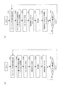
図26は、コリメートレンズ103の制御動作を説明する図である。同図(a)〜(c)は、コリメートレンズ103の駆動の流れを模式的に示す図、同図(d)は、コリメートレンズ103の制御動作を示すフローチャートである。
FIG. 26 is a diagram for explaining the control operation of the
同図(a)〜(c)に示すように、レンズアクチュエータ104は、コリメートレンズ103を光軸方向に変位可能に支持する支持部104aと、コリメートレンズ103を駆動するためのステッピングモータ104bを備えている。ステッピングモータ104bの回転軸にはリードスクリュー104cが装着され、リードスクリュー104cがコリメートレンズ103の軸受け103bに噛合している。ステッピングモータ104bが駆動されることにより、コリメートレンズ103が光軸方向にステップ送りされる。
As shown in FIGS. 4A to 4C, the
同図(d)を参照して、光ディスク装置にディスク10が装着され、ユーザから再生指令が入力されると、サーボ回路203は、まず、コリメートレンズ103の現在位置を参照する(S101)。次に、サーボ回路203は、コントローラ206から指示された再生対象の記録層(ターゲット層)に対応するコリメートレンズ103の設定位置(ステッピングモータのステップ数)を設定テーブル203aから読み取り、読み取った設定位置と、ステップS101で参照した現在位置との差に相当するステップ数だけステッピングモータ104bを駆動する(S102)。これにより、コリメートレンズ103は、たとえば、同図(b)に示す設定位置ST1に位置づけられる。
Referring to FIG. 4D, when the
その後、サーボ回路203は、対物レンズアクチュエータ109を駆動して、ターゲット層に対するフォーカス引き込みを行い、フォーカスサーボを開始する(S103)。しかる後、サーボ回路203は、上記球面収差信号に基づいて、コリメートレンズ103を最適位置に位置付けるための制御(以下、「球面収差サーボ」という)を行う(S104)。ここで、最適位置とは、球面収差信号がゼロ近傍となる位置のことである。
Thereafter, the
かかる球面収差サーボにおいて、サーボ回路203は、球面収差信号の極性と大きさを参照し、コリメートレンズ103を最適位置に位置づけるに必要な、ステッピングモータ104bのステップ数と回転方向を求める。そして、サーボ回路203は、当該回転方向に当該ステップ数だけステッピングモータ104を駆動する。
In such a spherical aberration servo, the
ここで、ステップ数は、演算により求めても良いし、あるいは、予めサーボ回路203内に、球面収差信号の大きさとステップ数の関係を規定するテーブルを保持しておき、このテーブルから読み出すようにしても良い。
Here, the number of steps may be obtained by calculation, or a table that defines the relationship between the magnitude of the spherical aberration signal and the number of steps is held in the
こうして、サーボ回路203は、コリメートレンズ103を最適位置に向かって移動させる。そして、この移動の後、サーボ回路203は、再度、球面収差信号の極性と大きさを参照し、コリメートレンズ103を最適位置に位置づけるに必要な、ステッピングモータ104bのステップ数と回転方向を求め、コリメートレンズ103を最適位置に向かって移動させる。
Thus, the
サーボ回路203は、かかるサーボ動作を、球面収差信号が、ゼロ近傍の予め定めた閾値範囲内になるまで繰り返す。これにより、コリメートレンズ103が、最適位置に位置づけられる。こうして、コリメートレンズ103が最適位置に位置づけられた後、再生動作が実行される(S105)。
The
再生動作の実行中、サーボ回路203は、再生回路202から入力されるアドレスデータを参照し、現在の再生位置が再生開始位置から半径方向に所定量だけ変化したかを判定する(S106)。この判定がNOのとき、サーボ回路203は、さらにターゲット層が変更される旨の信号がコントローラ206から入力されたかを判定する(S108)。ステップS106とステップS107の判定が何れもNOのとき、サーボ回路203は球面収差サーボを実行しない。したがって、コリメートレンズ103がステップS104で設定された位置に位置づけられた状態で、再生動作が進められる。
During execution of the reproduction operation, the
こうして再生動作が進み、現在の再生位置が再生開始位置から半径方向に所定量だけ変化すると(S106:YES)、サーボ回路203は、球面収差サーボを実行する(S107)。すなわち、サーボ回路203は、ステップS104と同様、球面収差信号の極性と大きさに基づいて、コリメートレンズ103を移動させ、コリメートレンズ103を最適位置に位置づける。
When the reproduction operation proceeds in this way and the current reproduction position changes by a predetermined amount in the radial direction from the reproduction start position (S106: YES), the
なお、球面収差サーボの実行中、再生動作は継続される。すなわち、本構成例では、図22(c)に示す如く、フォーカスエラー信号、トラッキングエラー信号および再生RF信号を生成するためのセンサとは別に配されたセンサSa1〜Sa4からの信号に基づいて、球面収差信号が独立して生成されるため、再生動作を進めながら球面収差サーボを実行することができる。 During the execution of the spherical aberration servo, the reproducing operation is continued. That is, in this configuration example, as shown in FIG. 22 (c), based on signals from sensors Sa1 to Sa4 arranged separately from sensors for generating a focus error signal, a tracking error signal, and a reproduction RF signal, Since the spherical aberration signal is generated independently, the spherical aberration servo can be executed while the reproduction operation is advanced.
こうして球面収差サーボを行うと、サーボ回路203は、サーボ完了時に再生回路202から入力されたアドレスデータを保持する。そして、サーボ回路203は、保持したアドレスデータと、その後の再生動作時に随時入力されるアドレスデータとを比較し、現在の再生位置が、先に球面収差サーボを行ったときの再生位置から半径方向に所定量だけ変化したかを判定する(S106)。そして、現在の再生位置が、先に球面収差サーボを行ったときの再生位置から半径方向に所定量だけ変化したと判定すると(S106:YES)、サーボ回路203は、再度、球面収差サーボを実行する(S107)。
When spherical aberration servo is performed in this way, the
なお、再生動作時に、同一のターゲット層上でジャンプ動作が行われると、ジャンプ後の再生位置が、先に球面収差サーボを行ったときの再生位置から半径方向に所定量だけ変化することが起こり得る(S106:YES)。この場合も、サーボ回路203は、上記と同様、球面収差サーボを実行し、コリメートレンズ103を最適位置に位置づける。
Note that if a jump operation is performed on the same target layer during the reproduction operation, the reproduction position after the jump may change by a predetermined amount in the radial direction from the reproduction position when the spherical aberration servo is performed first. Obtain (S106: YES). Also in this case, the
再生動作中に、コントローラ206からターゲット層を変更する旨の信号が入力されると(S108:YES)、S101以降の動作が行われる。すなわち、サーボ回路203は、コリメートレンズ103の現在位置を参照する(S101)。そして、変更後のターゲット層に対応するコリメートレンズ103の設定位置(ステッピングモータのステップ数)を設定テーブル203aから読み取り、読み取った設定位置とコリメートレンズ103の現在位置との差分に相当するステップ数だけステッピングモータ104bを駆動する(S102)。これにより、コリメートレンズ103は、たとえば、図26(c)に示す設定位置ST2に位置づけられる。
If a signal to change the target layer is input from the
その後、サーボ回路203は、対物レンズアクチュエータ109を駆動して、ターゲット層に対するフォーカス引き込みを行い、フォーカスサーボを開始する(S103)。しかる後、サーボ回路203は、球面収差サーボを行って、コリメートレンズ103を最適位置に位置づける(S104)。その後、当該ターゲット層に対する再生が実行される。
Thereafter, the
以上の如く、本構成に係る光ディスク装置によれば、フォーカスエラー信号、トラッキングエラー信号および再生RF信号とは別に、球面収差信号が独立して生成されるため、再生動作を進めながら球面収差サーボを実行することができる。 As described above, according to the optical disk apparatus according to the present configuration, the spherical aberration signal is generated independently of the focus error signal, tracking error signal, and reproduction RF signal. Can be executed.
また、本構成に係る光ディスク装置によれば、球面収差の発生の程度を示す球面収差信号に基づいてコリメートレンズ103の移動量が設定されるため、たとえば、ジッタや再生RF信号の振幅が最良になるようにコリメートレンズ103の位置を調整する場合に比べて、より迅速に、コリメートレンズ103を最適位置へと収束させることができる。
In addition, according to the optical disc apparatus according to the present configuration, the amount of movement of the
なお、本構成に係る光ディスク装置では、上記のように、再生位置が径方向に所定量だけ変化する毎に球面収差サーボが行われる。このように間欠的に球面収差サーボを行うようにしたのは、以下の理由に基づくものである。 In the optical disk apparatus according to this configuration, as described above, spherical aberration servo is performed every time the reproduction position changes by a predetermined amount in the radial direction. The reason why the spherical aberration servo is intermittently performed in this way is based on the following reason.
一般に、球面収差は、ディスク10のカバー層の厚み(以下、「カバー厚」という)や層間隔の変化に応じて発生する。ここで、ディスクのカバー厚や層間隔は、半径位置が同じであれば、ディスクの周方向には余り変化しない。ディスク10のカバー厚や層間隔は、半径位置の変化に伴って変化する場合がある。このため、球面収差も、ディスク半径位置の変化に伴って発生し易い。よって、球面収差の補正は、ディスク10に対するレーザ光の照射位置が半径方向にある程度変化したときに行えば良いと考えられる。上記では、この理由から、アドレスデータに基づいて間欠的に球面収差サーボが行われたが、この他、たとえば、再生時間が所定時間だけ経過する毎に球面収差サーボが行われるようにしても良い。
In general, spherical aberration occurs in accordance with changes in the thickness of the cover layer of the disk 10 (hereinafter referred to as “cover thickness”) and the layer spacing. Here, the cover thickness and the layer interval of the disk do not change much in the circumferential direction of the disk if the radial positions are the same. The cover thickness and the layer interval of the
なお、コリメートレンズ103や対物レンズ107がプラスチックレンズである場合、球面収差は、温度変化によっても発生する。本構成に係る光ディスク装置によれば、温度変化によって球面収差が発生しても、これが球面収差信号に反映される。このため、上記のように球面収差信号に基づいてコリメートレンズ103を補正することにより、カバー厚や層間隔の変化による球面収差以外に、温度変化に基づく球面収差をも補正することができる。したがって、本構成に係る光ディスク装置によれば、別途温度センサ等を用いることなく、温度変化に基づく球面収差を補正することができる。
Note that when the
なお、図26(d)のフローチャートでは、ターゲット層に対するフォーカス引き込みが完了した後(S103)、球面収差サーボが行われたが(S104)、フォーカスエラー信号がゼロクロスするタイミングで球面収差信号をサンプリングし、このサンプル値をもとにコリメートレンズ103を移動させるようにすれば、フォーカス引き込みに並行して、球面収差サーボを行うことができる。こうすると、フォーカス引き込みが完了する前に、コリメートレンズ103を最適位置に位置づけることも可能である。
In the flowchart of FIG. 26D, after the focus pull-in to the target layer is completed (S103), the spherical aberration servo is performed (S104), but the spherical aberration signal is sampled at the timing when the focus error signal crosses zero. If the
<光ディスク装置の変更例>
図26(d)のフローチャートでは、再生位置がディスク半径方向に所定量だけ変化する毎に球面収差サーボを行うようにしたが、本変更例では、再生時に常時、球面収差サーボが行われる。
<Example of optical disk device change>
In the flowchart of FIG. 26D, the spherical aberration servo is performed every time the reproduction position changes by a predetermined amount in the disk radial direction. However, in this modification, the spherical aberration servo is always performed during reproduction.
図27(a)は、本変更例に係るコリメートレンズ103の制御動作を示すフローチャートである。同図中、ステップS101〜S105、S108は、図26(d)のフローチャートと同じである。
FIG. 27A is a flowchart showing the control operation of the
本変更例では、図25の回路が、図28(a)のように変更される。図28(a)の回路では、図25の回路に比べ、LPF(ローパスフィルタ)325が追加されている。LPF325は、オペアンプ324からの出力を積分して球面収差信号Bを生成する。図28(a)の回路では、オペアンプ324の出力である球面収差信号Aと、LPF325の出力である球面収差信号Bの2種類の球面収差信号が生成される。
In this modification, the circuit of FIG. 25 is changed as shown in FIG. In the circuit of FIG. 28A, an LPF (low-pass filter) 325 is added compared to the circuit of FIG. The
図27(a)のステップS104では、図26(d)のステップS104と同様、図28(a)に示す球面収差信号Aを用いて球面収差サーボが行われる。 In step S104 in FIG. 27A, spherical aberration servo is performed using the spherical aberration signal A shown in FIG. 28A, as in step S104 in FIG.
本変更例では、ステップS105で再生が実行された後、再生期間中に亘って常時、ステップS110による球面収差サーボが行われる。ここで、ステップS110における球面収差サーボは、ステップS104の球面収差サーボと相違している。すなわち、ステップS110において、サーボ回路203は、図28(a)の球面収差信号Bを参照し、この球面収差信号Bが、ゼロ近傍の所定の閾値範囲を超えたときに、球面収差を抑制する方向に所定ステップ数だけコリメートレンズ103を移動させる。この動作は、球面収差信号Bが前記閾値範囲に引き込まれるまで繰り返される。これにより、コリメートレンズ103は、再生期間中、適正位置に位置づけられる。
In this modified example, after the reproduction is executed in step S105, the spherical aberration servo in step S110 is always performed over the reproduction period. Here, the spherical aberration servo in step S110 is different from the spherical aberration servo in step S104. That is, in step S110, the
なお、ステップS110においてサーボ回路203が球面収差信号Bに基づいてサーボを行うのは、次の理由からである。
Note that the
上記のとおり、球面収差は、ディスク10のカバー厚や層間隔の変化に応じて発生するが、ディスクの周方向においては、カバー厚や層間隔の変化よりも面振れ等の影響の方が大きくなる。よって、球面収差信号がレーザ光の周方向の移動に伴って高い周波数で細かく変化しても、コリメートレンズ103をこの変化に追従させる必要はないと考えられる。
As described above, spherical aberration occurs in accordance with changes in the cover thickness and layer spacing of the
一方、本変更例の光ディスク装置では、上述の如く、コリメートレンズ103がステッピングモータ104bによって駆動される。このように駆動源としてステッピングモータ104bを用いると、コリメートレンズ103の駆動レスポンスはあまり高くできない。この場合、ステッピングモータ104bに高い周波数でサーボ信号が印加されると、コリメートレンズ103は、これに正しく追従せずに、かえって、不所望な動きをする惧れがある。このため、ステッピングモータ104bには、ディスク回転周期よりも長い周期で、サーボ制御を行うのが望ましいと考えられる。
On the other hand, in the optical disk device of this modification, as described above, the
以上の理由から、本変更例では、ステップS110において、LPF325から出力された低周波数の球面収差信号Bに基づく球面収差サーボが行われる。LPF325は、ディスクが一回転する間に面ブレ等によって生じる高周波数の変動成分をSA信号からカットし、SA信号の直流成分(積分値)に応じた信号を球面収差信号Bとして出力する。こうして生成された球面収差信号Bをもとに、コリメートレンズ103が駆動されるため、本変更例のように駆動源としてステップングモータ104bを用いても、コリメートレンズ103を適正に制御することができる。
For the above reasons, in this modification, spherical aberration servo based on the low-frequency spherical aberration signal B output from the
なお、図27(a)のステップS104における球面収差サーボを、再生期間中に行われるステップS110と同様の球面収差サーボに置き換えることも可能である。すなわち、ステップS110において、LPF325からの出力である球面収差信号Bを球面収差サーボに用い、この球面収差信号Bがゼロ近傍の所定の閾値範囲を超えていれば、球面収差信号Bが閾値範囲に近づく方向に所定ステップ数だけコリメートレンズ103を移動させるよう制御を行っても良い。
Note that the spherical aberration servo in step S104 of FIG. 27A can be replaced with the same spherical aberration servo as in step S110 performed during the reproduction period. That is, in step S110, the spherical aberration signal B, which is the output from the
ただし、ステップS104では、設定テーブル203aから得られた設定位置から最適位置にコリメートレンズ103が引き込まれるため、このように制御を行うと、コリメートレンズ103を最適位置に引き込むのに時間が掛かる惧れがある。よって、この場合には、ステップS104における球面収差サーボを迅速化させる手段を講じるのが望ましい。
However, in step S104, since the
図27(b)は、図27(a)のステップS104において、ステップS110と同様の球面収差サーボを行う場合のフローチャートである。図27(b)のフローチャートでは、図27(a)のステップS104が、スップS111に置き換えられている。この場合、図28(a)の回路は、図28(b)の回路へと置き換えられる。 FIG. 27B is a flowchart when the same spherical aberration servo as that in step S110 is performed in step S104 in FIG. In the flowchart of FIG. 27B, step S104 of FIG. 27A is replaced with step S111. In this case, the circuit of FIG. 28A is replaced with the circuit of FIG.
図28(b)の回路では、抵抗326として可変抵抗が用いられ、差動増幅器のゲインが変更可能となっている。この回路により、図27(b)のステップS111における差動増幅器のゲイン(ゲイン=G1)が、ステップS112における再生期間中のゲイン(ゲイン=G2)よりも高められる。サーボ回路203は、ディスクに対する再生開始時または層間ジャンプ時にコントローラ206から入力される信号(ゲイン切り替え信号)に基づいて、抵抗326の抵抗値を変化させ、差動増幅器のゲインを高める。
In the circuit of FIG. 28B, a variable resistor is used as the
こうして、再生開始時または層間ジャンプ時に差動増幅器のゲインが高められて球面収差サーボの応答速度が高められることにより、コリメートレンズ103を迅速に最適位置に引き込むことができる。これにより、迅速に再生動作を実行することができる。
In this way, the gain of the differential amplifier is increased at the time of reproduction start or interlayer jump, and the response speed of the spherical aberration servo is increased, so that the
以上、光ディスク装置の構成例と変更例を説明したが、本発明の実施形態はこれに限定されるものではない。たとえば、上記には、ディスク10が複数の記録層を有する場合を例示したが、記録層を一つのみ有する光ディスクを再生対象とする光ディスク装置にも本発明を適用可能である。また、再生のみならず記録をも行う光ディスク装置にも本発明を適用可能である。
The configuration example and the modification example of the optical disc apparatus have been described above, but the embodiment of the present invention is not limited to this. For example, the case where the
なお、図28(b)の回路では、差動増幅器のゲインを変化させることにより、球面収差サーボの応答速度を変化させるようにしたが、LPFの時定数を変化させることにより球面収差サーボの応答速度を変化させるようにしても良い。 In the circuit of FIG. 28B, the response speed of the spherical aberration servo is changed by changing the gain of the differential amplifier, but the response of the spherical aberration servo is changed by changing the time constant of the LPF. The speed may be changed.
この他、本発明の実施の形態は、特許請求の範囲に示された技術的思想の範囲内において、適宜、種々の変更が可能である。 In addition, the embodiment of the present invention can be variously modified as appropriate within the scope of the technical idea shown in the claims.
101 半導体レーザ(レーザ光源)
104 レンズアクチュエータ(球面収差補正ユニット)
107 対物レンズ
109 対物レンズアクチュエータ(コマ収差補正ユニット)
110 検出レンズ(非点収差素子)
111 角度調整素子
112 光検出器
P11〜P18 センサ(第1のセンサ部)
Sa1〜Sa4 センサ(第2のセンサ部)
121、122 光検出器
130 角度調整素子
201 信号演算回路(第1の演算回路、第2の演算回路、演算回路)
203 サーボ回路(回路部)
325 ローパスフィルタ
101 Semiconductor laser (laser light source)
104 Lens actuator (spherical aberration correction unit)
107
110 Detection lens (astigmatism element)
111
Sa1 to Sa4 sensor (second sensor unit)
121, 122
203 Servo circuit (circuit part)
325 Low-pass filter
Claims (18)
前記レーザ光源から出射されたレーザ光を記録媒体上に収束させる対物レンズと、
前記記録媒体によって反射された前記レーザ光に非点収差を導入し、これにより、第1の方向に前記レーザ光が収束することによって生じる第1の焦線位置と、前記第1の方向に垂直な第2の方向に前記レーザ光が収束することによって生じる第2の焦線位置とを前記レーザ光の進行方向に互いに離間させる非点収差素子と、
前記記録媒体によって反射された前記レーザ光のうち、異なる4つの光束領域内の光束の進行方向を互いに異ならせ、これら4つの光束領域内の光束を互いに離散させる角度調整素子と、
前記離散された各光束を受光して検出信号を出力する光検出器と、
前記レーザ光に生じる球面収差を補正する球面収差補正ユニットと、
を備え、
前記角度調整素子は、前記第1の方向と前記第2の方向にそれぞれ平行で且つ互いにクロスする2つの直線の交点を前記レーザ光軸に整合させたとき、前記2つの直線によって作られる一組の対頂角が並ぶ方向に2つの前記光束領域が配置され、他の一組の対頂角が並ぶ方向に残りの2つの前記光束領域が配置されるよう、前記4つの光束領域を設定し、
前記光検出器は、前記4つの光束をそれぞれ受光する位置に配された第1のセンサ部と、球面収差による前記光束の強度分布の変化を検出する第2のセンサ部とを有する、
ことを特徴とする光ピックアップ装置。 A laser light source;
An objective lens for converging the laser light emitted from the laser light source onto a recording medium;
Astigmatism is introduced into the laser light reflected by the recording medium, and thereby the first focal line position generated by the laser light converging in the first direction and perpendicular to the first direction. An astigmatism element that separates a second focal line position generated by the convergence of the laser beam in the second direction from each other in the traveling direction of the laser beam;
An angle adjusting element for making the traveling directions of light beams in four different light beam regions different from each other among the laser beams reflected by the recording medium, and for separating the light beams in these four light beam regions;
A photodetector that receives each of the discrete luminous fluxes and outputs a detection signal;
A spherical aberration correction unit for correcting spherical aberration generated in the laser beam;
With
The angle adjusting element is a set formed by the two straight lines when an intersection of two straight lines parallel to and crossing each other in the first direction and the second direction is aligned with the laser optical axis. The four light flux regions are set so that the two light flux regions are arranged in the direction in which the vertical angles are aligned, and the remaining two light flux regions are arranged in the direction in which the other set of vertical angles are arranged,
The photodetector includes a first sensor unit disposed at a position for receiving the four light beams, and a second sensor unit that detects a change in the intensity distribution of the light beam due to spherical aberration.
An optical pickup device characterized by that.
前記4つの光束領域は、前記2つの直線によって前記レーザ光の光束領域を分割することにより設定されている、
ことを特徴とする光ピックアップ装置。 The optical pickup device according to claim 1,
The four light flux areas are set by dividing the laser light flux area by the two straight lines.
An optical pickup device characterized by that.
前記角度調整素子は、離散後の各光束が前記光検出器の受光面上において正方形の異なる4つの頂角の位置にそれぞれ導かれるよう、4つの前記光束領域の進行方向を、前記第1および第2の方向に対し45°の方向で、且つ、所定の角度だけ変化させる、
ことを特徴とする光ピックアップ装置。 The optical pickup device according to claim 1 or 2,
The angle adjusting element is configured to change the traveling directions of the four light beam regions so that the light beams after the separation are respectively guided to four apex angle positions different from each other on the light receiving surface of the photodetector. It is changed by a predetermined angle in a direction of 45 ° with respect to the second direction.
An optical pickup device characterized by that.
前記第2のセンサ部は、前記正方形の互いに対向する2つの辺の並び方向に配された2つのセンサと、残り2つの辺の並び方向に配された2つのセンサとを有する、
ことを特徴とする光ピックアップ装置。 The optical pickup device according to claim 3,
The second sensor unit has two sensors arranged in the arrangement direction of the two opposite sides of the square, and two sensors arranged in the arrangement direction of the remaining two sides.
An optical pickup device characterized by that.
前記正方形の互いに対向する2つの辺の並び方向に配された2つの前記センサにおける総受光量に対応する検出信号と、残り2つの辺の並び方向に配された2つの前記センサにおける総受光量に対応する検出信号の差分を演算する第1の演算回路を備える、
ことを特徴とする光ピックアップ装置。 The optical pickup device according to claim 4,
The detection signal corresponding to the total received light amount in the two sensors arranged in the arrangement direction of the two opposite sides of the square, and the total received light amount in the two sensors arranged in the arrangement direction of the remaining two sides A first arithmetic circuit that calculates a difference between detection signals corresponding to
An optical pickup device characterized by that.
前記第2のセンサ部を構成する4つの前記センサの各受光領域は、前記第1のセンサ部に囲まれた領域を、前記正方形の互いに対向する2つの頂点を結ぶ直線と残り2つの頂点を結ぶ直線によって4分割した領域となっている、
ことを特徴とする光ピックアップ装置。 The optical pickup device according to claim 4 or 5,
Each of the light receiving areas of the four sensors constituting the second sensor unit includes an area surrounded by the first sensor unit, a straight line connecting two opposite vertices of the square and the remaining two vertices. It is an area divided into four by connecting straight lines,
An optical pickup device characterized by that.
前記正方形の互いに対向する2つの頂点を結ぶ一つの直線によって4つの前記センサを2つのグループに区分したとき、一方のセンサグループにおける総受光量に対応する検出信号と、他方のセンサグループにおける総受光量に対応する検出信号の差分を演算する第2の演算回路を備える、
ことを特徴とする光ピックアップ装置。 The optical pickup device according to claim 6,
When the four sensors are divided into two groups by one straight line connecting two opposite vertices of the square, the detection signal corresponding to the total light reception amount in one sensor group and the total light reception in the other sensor group A second arithmetic circuit for calculating a difference between detection signals corresponding to the amount;
An optical pickup device characterized by that.
前記目標面によって反射された前記照射光に非点収差を導入し、これにより、第1の方向に前記照射光が収束することによって生じる第1の焦線位置と、前記第1の方向に垂直な第2の方向に前記照射光が収束することによって生じる第2の焦線位置とを前記照射光の進行方向に互いに離間させ、
前記目標面によって反射された前記照射光のうち、異なる4つの光束領域内の光束の進行方向を互いに異ならせて、これら4つの光束領域内の光束を互いに離散させ、
前記離散された各光束を光検出器にて受光し、
前記4つの光束領域は、前記第1の方向と前記第2の方向にそれぞれ平行で且つ互いにクロスする2つの直線の交点を前記照射光の光軸に整合させたとき、前記2つの直線によって作られる一組の対頂角が並ぶ方向に2つの前記光束領域が配置され、他の一組の対頂角が並ぶ方向に残りの2つの前記光束領域が配置されるように設定されており、
前記光検出器は、前記4つの光束をそれぞれ受光する位置に配された第1のセンサ部と、球面収差による前記光束の強度分布の変化を検出する第2のセンサ部とを有し、
前記第1のセンサ部から出力された検出信号に対し非点収差法に基づく演算処理を行ってフォーカスエラー信号を生成し、
前記第2のセンサ部から出力された検出信号に基づいて球面収差を表す信号を生成する、
ことを特徴とする焦点調整方法。 A focus adjustment method for positioning a focal position of irradiation light on a target surface,
Astigmatism is introduced into the irradiation light reflected by the target surface, whereby a first focal line position generated by the irradiation light converging in a first direction and perpendicular to the first direction. A second focal line position generated by convergence of the irradiation light in the second direction is spaced apart from each other in the traveling direction of the irradiation light,
Of the irradiation light reflected by the target surface, the traveling directions of the light beams in four different light beam regions are made different from each other, and the light beams in these four light beam regions are made discrete from each other,
Each of the discrete luminous fluxes is received by a photodetector,
The four light flux regions are formed by the two straight lines when the intersection of two straight lines that are parallel to and cross each other in the first direction and the second direction are aligned with the optical axis of the irradiation light. Two light flux regions are arranged in the direction in which the set of vertical angles are arranged, and the remaining two light flux regions are arranged in the direction in which the other set of vertical angles are arranged,
The photodetector includes a first sensor unit disposed at a position where each of the four light beams is received, and a second sensor unit that detects a change in the intensity distribution of the light beam due to spherical aberration,
A calculation process based on the astigmatism method is performed on the detection signal output from the first sensor unit to generate a focus error signal,
Generating a signal representing spherical aberration based on the detection signal output from the second sensor unit;
A focus adjustment method characterized by that.
前記光検出器からの信号を演算処理する演算回路と、
前記演算回路からの信号に基づいて前記対物レンズおよび前記球面収差補正ユニットを駆動制御するサーボ回路と、
を備えることを特徴する光ディスク装置。 An optical pickup device according to claim 1;
An arithmetic circuit for arithmetically processing a signal from the photodetector;
A servo circuit that drives and controls the objective lens and the spherical aberration correction unit based on a signal from the arithmetic circuit;
An optical disc apparatus comprising:
前記角度調整素子は、離散後の各光束が前記光検出器の受光面上において正方形の異なる4つの頂角の位置にそれぞれ導かれるよう、4つの前記光束領域の進行方向を、前記第1および第2の方向に対し45°の方向で、且つ、所定の角度だけ変化させる、
ことを特徴とする光ディスク装置。 The optical disc apparatus according to claim 9, wherein
The angle adjusting element is configured to change the traveling directions of the four light beam regions so that the light beams after the separation are respectively guided to four apex angle positions different from each other on the light receiving surface of the photodetector. It is changed by a predetermined angle in a direction of 45 ° with respect to the second direction.
An optical disc device characterized by the above.
前記第2のセンサ部は、前記正方形の互いに対向する2つの辺の並び方向に配された2つのセンサと、残り2つの辺の並び方向に配された2つのセンサとを有する、
ことを特徴とする光ディスク装置。 The optical disk apparatus according to claim 10, wherein
The second sensor unit has two sensors arranged in the arrangement direction of the two opposite sides of the square, and two sensors arranged in the arrangement direction of the remaining two sides.
An optical disc device characterized by the above.
前記演算回路は、前記正方形の互いに対向する2つの辺の並び方向に配された2つの前記センサにおける総受光量に対応する検出信号と、残り2つの辺の並び方向に配された2つの前記センサにおける総受光量に対応する検出信号の差分を演算する第1の演算回路を備え、
前記サーボ回路は、前記第1の演算回路による演算結果に基づいて、前記球面収差補正ユニットを制御する、
ことを特徴とする光ディスク装置。 The optical disk apparatus according to claim 11, wherein
The arithmetic circuit includes a detection signal corresponding to the total amount of received light in the two sensors arranged in the arrangement direction of the two opposite sides of the square, and the two signals arranged in the arrangement direction of the remaining two sides. A first arithmetic circuit that calculates a difference between detection signals corresponding to the total amount of light received by the sensor;
The servo circuit controls the spherical aberration correction unit based on a calculation result by the first calculation circuit.
An optical disc device characterized by the above.
前記第2のセンサ部を構成する4つの前記センサの各受光領域は、前記第1のセンサ部に囲まれた領域を、前記正方形の互いに対向する2つの頂点を結ぶ直線と残り2つの頂点を結ぶ直線によって4分割した領域となっている、
ことを特徴とする光ディスク装置。 The optical disk device according to claim 11 or 12,
Each of the light receiving areas of the four sensors constituting the second sensor unit includes an area surrounded by the first sensor unit, a straight line connecting two opposite vertices of the square and the remaining two vertices. It is an area divided into four by connecting straight lines,
An optical disc device characterized by the above.
前記レーザ光に生じるコマ収差を補正するコマ収差補正ユニットをさらに備え、
前記演算回路は、前記正方形の互いに対向する2つの頂点を結ぶ一つの直線によって4つの前記センサを2つのグループに区分したとき、一方のセンサグループにおける総受光量に対応する検出信号と、他方のセンサグループにおける総受光量に対応する検出信号の差分を演算する第2の演算回路を備え、
前記サーボ回路は、前記第2の演算回路による演算結果に基づいて、前記コマ収差補正ユニットを駆動制御する、
ことを特徴とする光ディスク装置。 The optical disk apparatus according to claim 13, wherein
A coma aberration correcting unit for correcting coma aberration generated in the laser beam;
The arithmetic circuit, when dividing the four sensors into two groups by one straight line connecting the two opposite vertices of the square, the detection signal corresponding to the total received light amount in one sensor group, and the other A second arithmetic circuit for calculating a difference between detection signals corresponding to the total amount of received light in the sensor group;
The servo circuit drives and controls the coma aberration correction unit based on a calculation result by the second calculation circuit.
An optical disc device characterized by the above.
前記サーボ回路は、光ディスクに対する再生または記録に並行して、前記球面収差補正ユニットを駆動制御する、
ことを特徴とする光ディスク装置。 The optical disk device according to any one of claims 9 to 14,
The servo circuit drives and controls the spherical aberration correction unit in parallel with reproduction or recording on the optical disc.
An optical disc device characterized by the above.
前記サーボ回路は、光ディスクに対する前記レーザ光の照射位置が前記光ディスクの径方向に所定量変化する毎に、前記球面収差補正ユニットを駆動制御する、
ことを特徴とする光ディスク装置。 The optical disk device according to any one of claims 9 to 14,
The servo circuit drives and controls the spherical aberration correction unit every time the irradiation position of the laser beam on the optical disc changes by a predetermined amount in the radial direction of the optical disc.
An optical disc device characterized by the above.
前記演算回路は、前記第2のセンサ部からの出力信号に基づいて前記球面収差に応じた収差信号を生成し、
前記光ディスク装置は、前記収差信号が入力されるローパスフィルタをさらに備え、
前記サーボ回路は、前記ローパスフィルタからの出力に基づいて前記球面収差補正ユニットを制御する、
ことを特徴とする光ディスク装置。 The optical disk device according to any one of claims 9 to 14,
The arithmetic circuit generates an aberration signal corresponding to the spherical aberration based on an output signal from the second sensor unit,
The optical disc apparatus further includes a low pass filter to which the aberration signal is input,
The servo circuit controls the spherical aberration correction unit based on an output from the low-pass filter;
An optical disc device characterized by the above.
前記光ディスクは、積層方向に複数の記録層を有し、
前記光ディスク装置は、前記ローパスフィルタの時定数を変化させるための回路部をさらに備え、
前記レーザ光の照射対象が第1の記録層から第2の記録層に切り替えられるとき、前記サーボ回路の応答速度が高められる、
ことを特徴とする光ディスク装置。 The optical disk apparatus according to claim 17, wherein
The optical disc has a plurality of recording layers in the stacking direction,
The optical disc apparatus further includes a circuit unit for changing a time constant of the low-pass filter,
When the object to be irradiated with the laser light is switched from the first recording layer to the second recording layer, the response speed of the servo circuit is increased.
An optical disc device characterized by the above.
Priority Applications (1)
| Application Number | Priority Date | Filing Date | Title |
|---|---|---|---|
| JP2009163888A JP5173953B2 (en) | 2008-08-01 | 2009-07-10 | Optical pickup device and optical disk device |
Applications Claiming Priority (3)
| Application Number | Priority Date | Filing Date | Title |
|---|---|---|---|
| JP2008200264 | 2008-08-01 | ||
| JP2008200264 | 2008-08-01 | ||
| JP2009163888A JP5173953B2 (en) | 2008-08-01 | 2009-07-10 | Optical pickup device and optical disk device |
Publications (2)
| Publication Number | Publication Date |
|---|---|
| JP2010055737A true JP2010055737A (en) | 2010-03-11 |
| JP5173953B2 JP5173953B2 (en) | 2013-04-03 |
Family
ID=41608243
Family Applications (1)
| Application Number | Title | Priority Date | Filing Date |
|---|---|---|---|
| JP2009163888A Expired - Fee Related JP5173953B2 (en) | 2008-08-01 | 2009-07-10 | Optical pickup device and optical disk device |
Country Status (2)
| Country | Link |
|---|---|
| US (1) | US7990835B2 (en) |
| JP (1) | JP5173953B2 (en) |
Cited By (1)
| Publication number | Priority date | Publication date | Assignee | Title |
|---|---|---|---|---|
| WO2012114583A1 (en) * | 2011-02-24 | 2012-08-30 | 三洋電機株式会社 | Light pick-up device |
Families Citing this family (8)
| Publication number | Priority date | Publication date | Assignee | Title |
|---|---|---|---|---|
| JP4610628B2 (en) * | 2008-03-04 | 2011-01-12 | 三洋電機株式会社 | Optical pickup device and focus adjustment method |
| JP4610662B2 (en) * | 2008-09-29 | 2011-01-12 | 三洋電機株式会社 | Optical pickup device and optical disk device |
| JP2012033230A (en) * | 2010-07-30 | 2012-02-16 | Sanyo Electric Co Ltd | Optical pickup device |
| JP2012033231A (en) * | 2010-07-30 | 2012-02-16 | Sanyo Electric Co Ltd | Optical pickup device |
| JP5571189B2 (en) * | 2010-11-24 | 2014-08-13 | 株式会社東芝 | Optical pickup and optical disk apparatus |
| JP2013012277A (en) * | 2011-06-29 | 2013-01-17 | Sanyo Electric Co Ltd | Optical pickup device |
| JP2013033582A (en) * | 2011-06-29 | 2013-02-14 | Sanyo Electric Co Ltd | Optical pickup device and position adjustment method for spectroscopic element |
| US8755260B2 (en) * | 2011-07-18 | 2014-06-17 | Marvell World Trade Ltd. | Collimator for optical pick-up units |
Citations (4)
| Publication number | Priority date | Publication date | Assignee | Title |
|---|---|---|---|---|
| JP2005044466A (en) * | 2003-07-25 | 2005-02-17 | Victor Co Of Japan Ltd | Spherical aberration compensating device |
| JP2007257803A (en) * | 2006-03-24 | 2007-10-04 | Sharp Corp | Controller and control method for optical pick-up, optical disk device, optical pick-up control program, and recording medium recording the program |
| JP2007335047A (en) * | 2006-06-19 | 2007-12-27 | Sony Corp | Optical disk apparatus and pickup device |
| JP2008171470A (en) * | 2007-01-09 | 2008-07-24 | Victor Co Of Japan Ltd | Optical pickup device |
Family Cites Families (8)
| Publication number | Priority date | Publication date | Assignee | Title |
|---|---|---|---|---|
| NL8105579A (en) * | 1981-12-11 | 1983-07-01 | Philips Nv | OPTICAL FOCUS ERROR DETECTION SYSTEM. |
| US5577018A (en) * | 1992-02-07 | 1996-11-19 | Sony Corporation | Phase changing apparatus and optical pickup apparatus for magneto-optic storage device using same |
| US6967908B2 (en) * | 2000-09-07 | 2005-11-22 | Pioneer Corporation | Optical pickup device with focus error detecting optical element and method for focus error detection |
| JP2002109778A (en) * | 2000-09-29 | 2002-04-12 | Pioneer Electronic Corp | Optical pickup device |
| US7245565B2 (en) * | 2002-10-10 | 2007-07-17 | Matsushita Electric Industrial Co., Ltd. | Optical head and optical disk unit |
| JP4859089B2 (en) | 2005-03-14 | 2012-01-18 | 株式会社リコー | Extraction optical system, optical pickup device, and optical disc device |
| JP2006260669A (en) | 2005-03-16 | 2006-09-28 | Ricoh Co Ltd | Optical information recording and reproducing apparatus and recording medium |
| US20080165655A1 (en) * | 2007-01-09 | 2008-07-10 | Ryo Saitoh | Optical pickup device |
-
2009
- 2009-07-10 JP JP2009163888A patent/JP5173953B2/en not_active Expired - Fee Related
- 2009-07-30 US US12/512,440 patent/US7990835B2/en not_active Expired - Fee Related
Patent Citations (4)
| Publication number | Priority date | Publication date | Assignee | Title |
|---|---|---|---|---|
| JP2005044466A (en) * | 2003-07-25 | 2005-02-17 | Victor Co Of Japan Ltd | Spherical aberration compensating device |
| JP2007257803A (en) * | 2006-03-24 | 2007-10-04 | Sharp Corp | Controller and control method for optical pick-up, optical disk device, optical pick-up control program, and recording medium recording the program |
| JP2007335047A (en) * | 2006-06-19 | 2007-12-27 | Sony Corp | Optical disk apparatus and pickup device |
| JP2008171470A (en) * | 2007-01-09 | 2008-07-24 | Victor Co Of Japan Ltd | Optical pickup device |
Cited By (1)
| Publication number | Priority date | Publication date | Assignee | Title |
|---|---|---|---|---|
| WO2012114583A1 (en) * | 2011-02-24 | 2012-08-30 | 三洋電機株式会社 | Light pick-up device |
Also Published As
| Publication number | Publication date |
|---|---|
| US20100027405A1 (en) | 2010-02-04 |
| US7990835B2 (en) | 2011-08-02 |
| JP5173953B2 (en) | 2013-04-03 |
Similar Documents
| Publication | Publication Date | Title |
|---|---|---|
| JP5173953B2 (en) | Optical pickup device and optical disk device | |
| US7558162B2 (en) | Optical pick-up head, optical information apparatus, and optical information reproducing method | |
| JP4610662B2 (en) | Optical pickup device and optical disk device | |
| US7746736B2 (en) | Optical head and optical disk device capable of detecting spherical aberration | |
| JP4610628B2 (en) | Optical pickup device and focus adjustment method | |
| JP5173659B2 (en) | Optical pickup device and optical disk device | |
| JP5173656B2 (en) | Optical pickup device | |
| JPH11259893A (en) | Optical head, recording and/or reproducing device, recording and/or reproducing method, and thickness detecting method | |
| JP4684341B2 (en) | Optical pickup device, optical disk device, and focus adjustment method | |
| JP2002092932A (en) | Optical head, light receiving and transmitting element, and recording and reproducing device for optical recording medium | |
| JP2011070752A (en) | Optical pickup device | |
| JP4722190B2 (en) | Optical pickup device and optical disk device | |
| JP2011008852A (en) | Optical pickup device | |
| JP5227930B2 (en) | Optical pickup device | |
| JP4722205B2 (en) | Optical pickup device and optical disk device | |
| JP5173868B2 (en) | Optical pickup device and optical disk device | |
| JP2006309858A (en) | Optical disk device | |
| JP3685797B2 (en) | Optical disk device | |
| JP2008047199A (en) | Optical pickup | |
| JP2010079983A (en) | Optical pickup device and optical disk device | |
| JP2010049758A (en) | Optical pickup device | |
| JP2006513515A (en) | Device for reading from and / or writing to optical recording media | |
| JP2005174503A (en) | Optical pickup and optical disk drive | |
| JP2008047198A (en) | Optical pickup | |
| JP2010080005A (en) | Optical pickup device and optical disk device |
Legal Events
| Date | Code | Title | Description |
|---|---|---|---|
| A621 | Written request for application examination |
Free format text: JAPANESE INTERMEDIATE CODE: A621 Effective date: 20120622 |
|
| A977 | Report on retrieval |
Free format text: JAPANESE INTERMEDIATE CODE: A971007 Effective date: 20121108 |
|
| A131 | Notification of reasons for refusal |
Free format text: JAPANESE INTERMEDIATE CODE: A131 Effective date: 20121113 |
|
| A521 | Written amendment |
Free format text: JAPANESE INTERMEDIATE CODE: A523 Effective date: 20121116 |
|
| TRDD | Decision of grant or rejection written | ||
| A01 | Written decision to grant a patent or to grant a registration (utility model) |
Free format text: JAPANESE INTERMEDIATE CODE: A01 Effective date: 20121204 |
|
| A61 | First payment of annual fees (during grant procedure) |
Free format text: JAPANESE INTERMEDIATE CODE: A61 Effective date: 20121227 |
|
| FPAY | Renewal fee payment (event date is renewal date of database) |
Free format text: PAYMENT UNTIL: 20160111 Year of fee payment: 3 |
|
| LAPS | Cancellation because of no payment of annual fees |