EP4583080A2 - Kameraendoskop für chirurgische simulation - Google Patents
Kameraendoskop für chirurgische simulation Download PDFInfo
- Publication number
- EP4583080A2 EP4583080A2 EP25163160.2A EP25163160A EP4583080A2 EP 4583080 A2 EP4583080 A2 EP 4583080A2 EP 25163160 A EP25163160 A EP 25163160A EP 4583080 A2 EP4583080 A2 EP 4583080A2
- Authority
- EP
- European Patent Office
- Prior art keywords
- sensor
- mount
- cylindrical
- circuit board
- flexible circuit
- Prior art date
- Legal status (The legal status is an assumption and is not a legal conclusion. Google has not performed a legal analysis and makes no representation as to the accuracy of the status listed.)
- Pending
Links
Images










Classifications
-
- G—PHYSICS
- G09—EDUCATION; CRYPTOGRAPHY; DISPLAY; ADVERTISING; SEALS
- G09B—EDUCATIONAL OR DEMONSTRATION APPLIANCES; APPLIANCES FOR TEACHING, OR COMMUNICATING WITH, THE BLIND, DEAF OR MUTE; MODELS; PLANETARIA; GLOBES; MAPS; DIAGRAMS
- G09B23/00—Models for scientific, medical, or mathematical purposes, e.g. full-sized devices for demonstration purposes
- G09B23/28—Models for scientific, medical, or mathematical purposes, e.g. full-sized devices for demonstration purposes for medicine
-
- A—HUMAN NECESSITIES
- A61—MEDICAL OR VETERINARY SCIENCE; HYGIENE
- A61B—DIAGNOSIS; SURGERY; IDENTIFICATION
- A61B1/00—Instruments for performing medical examinations of the interior of cavities or tubes of the body by visual or photographical inspection, e.g. endoscopes; Illuminating arrangements therefor
- A61B1/00064—Constructional details of the endoscope body
- A61B1/00071—Insertion part of the endoscope body
- A61B1/0008—Insertion part of the endoscope body characterised by distal tip features
- A61B1/00096—Optical elements
-
- A—HUMAN NECESSITIES
- A61—MEDICAL OR VETERINARY SCIENCE; HYGIENE
- A61B—DIAGNOSIS; SURGERY; IDENTIFICATION
- A61B1/00—Instruments for performing medical examinations of the interior of cavities or tubes of the body by visual or photographical inspection, e.g. endoscopes; Illuminating arrangements therefor
- A61B1/00064—Constructional details of the endoscope body
- A61B1/0011—Manufacturing of endoscope parts
-
- A—HUMAN NECESSITIES
- A61—MEDICAL OR VETERINARY SCIENCE; HYGIENE
- A61B—DIAGNOSIS; SURGERY; IDENTIFICATION
- A61B1/00—Instruments for performing medical examinations of the interior of cavities or tubes of the body by visual or photographical inspection, e.g. endoscopes; Illuminating arrangements therefor
- A61B1/04—Instruments for performing medical examinations of the interior of cavities or tubes of the body by visual or photographical inspection, e.g. endoscopes; Illuminating arrangements therefor combined with photographic or television appliances
- A61B1/042—Instruments for performing medical examinations of the interior of cavities or tubes of the body by visual or photographical inspection, e.g. endoscopes; Illuminating arrangements therefor combined with photographic or television appliances characterised by a proximal camera, e.g. a CCD camera
-
- A—HUMAN NECESSITIES
- A61—MEDICAL OR VETERINARY SCIENCE; HYGIENE
- A61B—DIAGNOSIS; SURGERY; IDENTIFICATION
- A61B1/00—Instruments for performing medical examinations of the interior of cavities or tubes of the body by visual or photographical inspection, e.g. endoscopes; Illuminating arrangements therefor
- A61B1/04—Instruments for performing medical examinations of the interior of cavities or tubes of the body by visual or photographical inspection, e.g. endoscopes; Illuminating arrangements therefor combined with photographic or television appliances
- A61B1/05—Instruments for performing medical examinations of the interior of cavities or tubes of the body by visual or photographical inspection, e.g. endoscopes; Illuminating arrangements therefor combined with photographic or television appliances characterised by the image sensor, e.g. camera, being in the distal end portion
- A61B1/051—Details of CCD assembly
-
- A—HUMAN NECESSITIES
- A61—MEDICAL OR VETERINARY SCIENCE; HYGIENE
- A61B—DIAGNOSIS; SURGERY; IDENTIFICATION
- A61B1/00—Instruments for performing medical examinations of the interior of cavities or tubes of the body by visual or photographical inspection, e.g. endoscopes; Illuminating arrangements therefor
- A61B1/313—Instruments for performing medical examinations of the interior of cavities or tubes of the body by visual or photographical inspection, e.g. endoscopes; Illuminating arrangements therefor for introducing through surgical openings, e.g. laparoscopes
-
- A—HUMAN NECESSITIES
- A61—MEDICAL OR VETERINARY SCIENCE; HYGIENE
- A61B—DIAGNOSIS; SURGERY; IDENTIFICATION
- A61B90/00—Instruments, implements or accessories specially adapted for surgery or diagnosis and not covered by any of the groups A61B1/00 - A61B50/00, e.g. for luxation treatment or for protecting wound edges
- A61B90/36—Image-producing devices or illumination devices not otherwise provided for
- A61B90/361—Image-producing devices, e.g. surgical cameras
-
- G—PHYSICS
- G02—OPTICS
- G02B—OPTICAL ELEMENTS, SYSTEMS OR APPARATUS
- G02B23/00—Telescopes, e.g. binoculars; Periscopes; Instruments for viewing the inside of hollow bodies; Viewfinders; Optical aiming or sighting devices
- G02B23/24—Instruments or systems for viewing the inside of hollow bodies, e.g. fibrescopes
- G02B23/2407—Optical details
- G02B23/2423—Optical details of the distal end
-
- G—PHYSICS
- G02—OPTICS
- G02B—OPTICAL ELEMENTS, SYSTEMS OR APPARATUS
- G02B23/00—Telescopes, e.g. binoculars; Periscopes; Instruments for viewing the inside of hollow bodies; Viewfinders; Optical aiming or sighting devices
- G02B23/24—Instruments or systems for viewing the inside of hollow bodies, e.g. fibrescopes
- G02B23/2476—Non-optical details, e.g. housings, mountings, supports
-
- G—PHYSICS
- G02—OPTICS
- G02B—OPTICAL ELEMENTS, SYSTEMS OR APPARATUS
- G02B23/00—Telescopes, e.g. binoculars; Periscopes; Instruments for viewing the inside of hollow bodies; Viewfinders; Optical aiming or sighting devices
- G02B23/24—Instruments or systems for viewing the inside of hollow bodies, e.g. fibrescopes
- G02B23/2476—Non-optical details, e.g. housings, mountings, supports
- G02B23/2484—Arrangements in relation to a camera or imaging device
-
- G—PHYSICS
- G09—EDUCATION; CRYPTOGRAPHY; DISPLAY; ADVERTISING; SEALS
- G09B—EDUCATIONAL OR DEMONSTRATION APPLIANCES; APPLIANCES FOR TEACHING, OR COMMUNICATING WITH, THE BLIND, DEAF OR MUTE; MODELS; PLANETARIA; GLOBES; MAPS; DIAGRAMS
- G09B23/00—Models for scientific, medical, or mathematical purposes, e.g. full-sized devices for demonstration purposes
- G09B23/28—Models for scientific, medical, or mathematical purposes, e.g. full-sized devices for demonstration purposes for medicine
- G09B23/285—Models for scientific, medical, or mathematical purposes, e.g. full-sized devices for demonstration purposes for medicine for injections, endoscopy, bronchoscopy, sigmoidscopy, insertion of contraceptive devices or enemas
-
- G—PHYSICS
- G09—EDUCATION; CRYPTOGRAPHY; DISPLAY; ADVERTISING; SEALS
- G09B—EDUCATIONAL OR DEMONSTRATION APPLIANCES; APPLIANCES FOR TEACHING, OR COMMUNICATING WITH, THE BLIND, DEAF OR MUTE; MODELS; PLANETARIA; GLOBES; MAPS; DIAGRAMS
- G09B23/00—Models for scientific, medical, or mathematical purposes, e.g. full-sized devices for demonstration purposes
- G09B23/28—Models for scientific, medical, or mathematical purposes, e.g. full-sized devices for demonstration purposes for medicine
- G09B23/30—Anatomical models
Definitions
- the lens mount in various embodiments, has a proximal end and a distal end and the sensor mount has a proximal end and a distal end such that the proximal end of the sensor mount is parallel to the distal end of the sensor mount and the proximal end of the lens mount and orthogonal to the longitudinal axis of the elongate shaft.
- a simulation surgical camera scope comprising at least one of a lens mount and/or a sensor mount.
- a simulation surgical camera scope comprises a handle, a cylindrical elongate shaft having a proximal end coupled to the handle and a distal end.
- the cylindrical elongate shaft comprises a cylindrical sensor mount and a cylindrical lens mount in which the cylindrical lens mount has threads disposed on an inner surface of the cylindrical lens mount.
- a cylindrical lens has threads disposed on an outer surface of the lens and is arranged to mate with the threads of the cylindrical lens mount and the cylindrical lens mount has a pocket, a center aperture and/or at least one pin hole positioned next to the pocket.
- a simulation surgical camera scope is provided to assist in laparoscopic surgical skill training and simulation.
- the environment for training laparoscopic surgical skills can include a box trainer that is intended to simulate the human abdominal area.
- the trainer in various embodiments includes a penetrable cover that simulates an abdominal wall through which surgical instruments and scopes are inserted to access the simulated body cavity that houses artificial organs or skills training models upon which mock surgical procedures are practiced.
- Real surgical or surgical-grade scopes may be employed in a training environment. Surgical-grade scopes are high quality, calibrated, precision instruments, have very limited optical distortion, and provide enough light to completely illuminate the cavity. Surgical-grade scopes however are also very expensive costing thousands of dollars.
- the optical performance of a simulation surgical scope should be similar to surgical-grade scopes with respect to certain characteristics. These characteristics include, but are not limited to, working distance, depth-of-field, field-of-view, image color and/or image quality. Some of these characteristics are schematically depicted in FIG. 1 for readability of the description and not a suggestion of prior art or admission of such. Image quality can include the sharpness of the video images in terms of pixel count resolution and the corresponding frames per second (fps) of the video feed.
- the simulation surgical scope in accordance with various embodiments provides an image quality that is approximately 640x480 to 720x1024 at approximately 24-60 fps.
- the simulation surgical scope in accordance with various embodiments provides an approximate to the actual colors of an object when observed with the naked eye.
- the lighting employed at the tip of the training scope should not distort the colors of the organ models so that the realism of the simulation is not compromised.
- the working distance which is the distance from the lens to the optimal focal plane is shown in FIG. 1 , which is the plane of best focus.
- the depth-of-field is defined as the distance away from the optimal focal plane in both directions in which the image is still in focus.
- the depth-of-field should be as wide as possible.
- the field-of-view is defined as the area in the displayed image at the working distance.
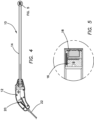
- the scope 10 in accordance with various embodiments includes a handle 12 connected to an elongated shaft 14.
- a sensor assembly 16 and lens assembly 18 are located inside the scope 10 and connected to the elongated shaft 14.
- the sensor assembly 16 is connected to a controller printed circuit board assembly (PCBA) 20 located inside the handle 12.
- PCBA printed circuit board assembly
- the scope 10 is connectable to a computer or video monitor wirelessly or via a cable 22, such as a USB cable, and configured to display the captured video image.
- the handle 12 is a two-piece, clamshell design that defines an interior and houses the controller PCBA 20.
- the PCBA is connected to the sensor assembly 16 and to an output cable 22 that is in turn connected to a computer or video monitor in order to display a video image captured by a sensor and processed by a microcontroller on the controller PCBA.
- the elongated shaft 14 is connected to the distal end of the handle 12.
- the handle 12 is provided with one or more buttons connected to a microcontroller on the PCBA to control the power and lighting of the scope 10.
- the lumen of the elongated shaft 14 opens to the interior of the handle 12 in order to connect the sensor assembly 16 to the PCBA 20.
- the elongated shaft 14 includes a sidewall having a cylindrical shape defining a lumen.
- the shaft 14 includes a proximal end and a distal end.
- the proximal end of the shaft 14 is connected to the handle 12 and includes a proximal opening such that the lumen of the shaft 14 opens to the interior of the handle 12.
- the distal end of the shaft 14 includes a distal opening.
- the diameter of the shaft 14 is approximately between 3mm to 15mm.
- the outside diameter is sized to fit inside a correspondingly sized trocar. For example, if the outside diameter of the shaft 14 is 10mm, the inside diameter of the trocar is greater than 10mm.
- the inner diameter of a 10mm shaft 14 is approximately 8mm.
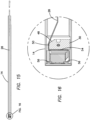
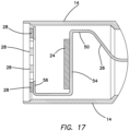
- the inner diameter of the shaft is stepped to a larger diameter at the distal end relative to the inner diameter at the proximal end as can be seen in FIGs. 16-17 .
- the length of the shaft 14 is approximately 30-36cm.
- the length from the handle 12 to the distal end of the shaft 14 is approximately 33cm.
- the sensor assembly 16 includes a sensor 24 and lights 28 mounted on an electrical connector 26.
- the sensor assembly 16 further includes a sensor mount 30.
- the sensor mount 30 is connected to the elongated shaft 14 via an indexing, mounting pin 32.
- the sensor mount 30 is sized and configured to provide a backing and support for the sensor 24 and connector 26.
- the sensor mount 30 is partially cylindrical in shape and is sized to fit closely within the lumen of the elongated shaft 14.
- the sensor mount 30 has a proximal end and a distal end interconnected by a sidewall.
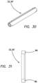
- Two pin holes 34 are provided extending parallel to the longitudinal axis of the shaft 14.
- the pin holes 34 extend between the proximal end and the distal end and are sized and configured to receive a pin 36' or dowel 36 in each pin hole 34.
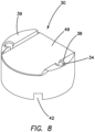
- Each pin hole 34 includes a beveled entry 38 at the distal end of the pin hole 34 as can be seen in FIG. 8 .
- Another pin hole 44 that is traverse to the longitudinal axis of the elongated shaft 14 is provided in the sensor mount 30 and extends through the sensor mount 30 between the sidewall. As can be seen in FIG. 9 , the traverse pin hole 44 also includes an enlarged diameter portion 46 to facilitate insertion of a pin 32 as well as alignment and setting of the sensor mount 30 with respect to the elongated shaft 14.
- the pin 32 is longer than the dowel 36 or pin 36' employed in pin holes 34.
- the proximal end of the sensor mount 30 includes a channel-like groove 42 sized and configured to receive an instrument such as a flat-head screwdriver.
- the groove 42 assists in the installation of the sensor mount 30 within the elongated shaft 14.
- an instrument can be inserted into the groove 42 in order to help hold and move the sensor mount 30 into the lumen of the elongated shaft 14, hold the sensor mount 30 in position inside the elongated shaft 14, rotate the sensor mount 30 with respect to the elongated shaft 14, align the sensor mount 30 with respect to corresponding pin holes formed in the elongated shaft 14, and/or generally hold the sensor mount 30 stationary with respect to elongated shaft 14.
- the proximal end of the sensor mount 30 is substantially parallel to the distal end of the sensor mount 30.
- the proximal end of the sensor mount 30 also includes an angled surface 48 interconnected with a flat portion 50 of the sidewall.
- the angled surface 48 together with the flat portion 50 provide a landing and pathway for the connector 26 extending proximally inside the elongated shaft 14 to the PCBA 20 located in the handle 12.
- the distal end of the sensor mount 30 includes a bevel 52 at the intersection of the distal end with the flat portion 50 of the sidewall.
- the bevel 52 helps to provide a smooth bend in the connector 26 to prevent a sharp bend and associated stress concentrations in the connector 26.
- the distal end of the sensor mount also includes raised surfaces 39 disposed on either side of a middle, flat cavity or surface 49.
- the sensor and connector 26 are positioned on the middle, flat surface 49 of the sensor mount 30. It has been found that due to the limitations in size and dimensions of the distal end of the scope and the need for the precise placement of the sensor relative to the lens, the sensor is often crushed or damaged between the sensor and lens mounts. As such, raised surfaces 39 act as a hard stop to prevent crushing of the sensor between the sensor mount and lens mount. Thus, the dimensions and tolerance of the raised surfaces relative to the middle surface are such that when the sensor mount and lens mount are coupled or connected together with the sensor and connector between them, the sensor is not crushed.
- the sensor and/or lens mount are configured to ensure that the spacing between the lens and sensor mounts is greater than the thickness of the sensor and the flexible printed circuit board and yet smaller than or no greater than the depth of focus range of the lens thereby ensuring the sensor is always located within the depth of focus, ensuring image quality is maintained and the sensor is not damaged.
- the height of the raised surface relative to the middle surface of the sensor mount is not greater than the depth of focus range of the lens.
- the light sensing portion of the senor is indexed to the lens mount to keep the crucial distance between the sensor and lens consistent.
- the sensor mount without raised surfaces and the lens mount are brought together with less pressure than would crush the sensor.
- Force or pressure gauges or other similar force or pressure limiting components would be utilized to ensure that the threshold crush pressure of the sensor is not exceeded.
- the raised surfaces extends further from the middle surface, i.e., have a greater height or are larger in the axial direction, resulting in a bigger gap or spacing between lens and sensor mounts when assembled.
- a mechanical spring or a material with spring like attributes, like silicone is placed in the gap or spacing that is created by the raised surfaces, thus taking up the resulting gap of having the raised surfaces further from the middle, flat surface.
- the sensor can be indexed, with a set screw coming from the proximal end of the sensor mount or similarly through the use of shim stock, to push the sensor against the lens mount.
- the connector 26 is a flexible circuit board or flexboard 26.
- the flexboard 26, in one embodiment, is approximately 17 inches long, approximately 0.10 inches wide and approximately 0.015 inches thick.
- the flexboard 26 is a connective device that provides an electrical connection between electrical components.
- the flexboard 26 is connected to the sensor 24 and lights 28, extends along the length of the shaft 14 and connects to the PCBA 20 inside the handle 12.
- the flexboard 26 reduces wiring errors during assembly, reduces assembly time and costs, eliminates mechanical connectors and provides design flexibility including highly complex configurations and provides a support for surface mounted devices.
- the flexboard 26 can be made to conform to a desired shape and flex during use and installation.
- the flexboard 26 is substantially planar and is connected at its proximal end to the PCBA 20 inside the handle 12.
- the flexboard 26 extends distally inside the shaft 14 as can be seen in FIG. 15 .
- the flexboard 26 will twist approximately 90 degrees within the shaft 14 to facilitate connection with the sensor assembly 16 at the distal end and the PCBA 20 at the proximal end.
- the lighting or LED location 56 of the flexboard 26 is where the lights/LEDs 28 are connected to the flexboard 26.
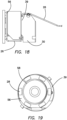
- the LED location 56 is flat and includes a central opening 58 as can be seen in FIGs. 6 and 19 .
- the central opening 58 permits unobstructed and illuminated viewing via the lens assembly 18.
- the lights 28 are a plurality of LEDs connected to the flexboard 26 with electrically conductive solder or adhesive and arranged in a circle around the central opening 58 and around the lens prior to assembly with the rest of the scope components.
- the flexboard 26 forms an S-shaped pathway as can be seen in FIGs. 16-18 .
- the flexboard 26 includes electrical contacts for the LEDs 28 and image sensor 24 and traces that allow power and data to be transmitted to the controller PCBA 20.
- the flexboard 26 also locates the LEDs 28 and image sensor 24 for assembly with the rest of the components in the shaft 14.
- the flexboard 26 eliminates the use of wires, is flat and smaller than an equivalent wire bundle it is replacing and can be designed and configured to meet the confines of the shaft dimension and assembly components. Furthermore, due to the sensor 24 being placed at the distal end of the scope and the controller PCBA 20 being positioned at the proximal end of the scope and the speed and/or amount of data being transmitted, the signal integrity between the components can degrade.
- the flexboard 26, in various embodiments, being a single monolithic component ensures that signal integrity of data transfer from the image sensor 24 is not compromised.
- the flexboard includes, integrated or attached, a metallic layer, e.g., a copper only layer, to ensure signal integrity is maintained.
- the metallic layer is sized and dimensioned in various embodiments to shield the flexboard from outside electrical noise that can interfere with the signals transmitted through the traces on the flexboard, especially the high speed data lines.
- the flexboard 26 is sufficiently flexible to navigate the S-shaped pathway making multiple approximately 90-degree bends to meet the design of the sensor assembly 16 and lens assembly 18.
- a ring of LEDs 28 are employed in the sensor assembly 16 and arrayed around the lens assembly as can be seen in FIG. 19 .
- the LEDs 28 serve to illuminate the target object and surgical field. Approximately, 4-8 white LEDs 28 are used depending on the brightness required for a particular application or to allow use in all conditions including confined procedures such as transanal minimally invasive surgery (TAMIS) which may require more lighting.
- the LEDs may be selected to have an appropriate color temperature, or tinted, e.g., via tinted glass 67, to optimize color matching.
- the sensor 24, in one embodiment, is a CMOS image sensor such as one produced by OmniVision Technologies, Inc. It is a 1 ⁇ 4 sensor sized to fit within a 10mm shaft 14.
- the sensor 24 supports video quality maximums of 720 pixels at 60 fps and has a resolution of 640x480 characteristic of the VGA hardware at 90 fps.
- the sensor 24 supports a video output format of YUV422 and has inter-integrated circuit communications to communicate with a microprocessor and has a camera serial interface 2 (CSI-2) mobile industry processor interface (MIPI) for the video communications. Sensors that would be small enough to fit within a 5mm tube do not have the associated microprocessor, electronics and demosaicing algorithm to output in YUV422.
- CSI-2 camera serial interface 2
- MIPI mobile industry processor interface
- the lens assembly 18 in accordance with various embodiments includes a lens 62, a lens housing 64, a lens mount 66, a tinted glass 67, a cover glass 68 and/or combinations thereof.
- the lens 62 in various embodiments may include one or more lenses and optical elements.
- the lens 62 includes an optical train having four lenses and an infrared filter.
- the lens 62 has a 3.8mm focal length and is aspheric and achromatic. This configuration provides a working distance of approximately 50-70mm, a depth-of-field of approximately 90-150mm and a field-of-view of 60-65 degrees.
- the lens housing 64 further includes one or more notch, socket or the like 88 configured for receiving a distal end of a correspondingly shaped instrument.
- the instrument is inserted into the notch/socket 88 of the lens housing 64 in order to rotate the lens housing 64 with respect to the lens mount 66 for optically tuning the lens assembly.
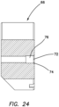
- the lens mount 66 includes a proximal end and a distal end interconnected by a sidewall.
- the lens mount 66 includes a central lumen 70 extending between an opening at the proximal end and an opening at the distal end.
- the lens mount 66 is partially cylindrical and is sized to fit closely within the lumen of the elongated shaft 14.
- the central lumen 70 includes a threaded inner surface for engaging the threads on the outer surface of the lens housing 64 such that, when threaded into the lens mount 66, the lens 62 moves along the longitudinal axis.
- the lens mount 66 includes two pin holes 72 that extend between the proximal end and the distal end.
Landscapes
- Physics & Mathematics (AREA)
- Health & Medical Sciences (AREA)
- Life Sciences & Earth Sciences (AREA)
- Engineering & Computer Science (AREA)
- Surgery (AREA)
- Optics & Photonics (AREA)
- General Health & Medical Sciences (AREA)
- Medical Informatics (AREA)
- General Physics & Mathematics (AREA)
- Radiology & Medical Imaging (AREA)
- Molecular Biology (AREA)
- Heart & Thoracic Surgery (AREA)
- Biomedical Technology (AREA)
- Nuclear Medicine, Radiotherapy & Molecular Imaging (AREA)
- Animal Behavior & Ethology (AREA)
- Pathology (AREA)
- Public Health (AREA)
- Veterinary Medicine (AREA)
- Biophysics (AREA)
- Astronomy & Astrophysics (AREA)
- Chemical & Material Sciences (AREA)
- Educational Technology (AREA)
- Algebra (AREA)
- Mathematical Analysis (AREA)
- Mathematical Optimization (AREA)
- Mathematical Physics (AREA)
- Pure & Applied Mathematics (AREA)
- Business, Economics & Management (AREA)
- Educational Administration (AREA)
- Computational Mathematics (AREA)
- Theoretical Computer Science (AREA)
- Medicinal Chemistry (AREA)
- Manufacturing & Machinery (AREA)
- Multimedia (AREA)
- Pulmonology (AREA)
- Oral & Maxillofacial Surgery (AREA)
- Endoscopes (AREA)
- Studio Devices (AREA)
- Instruments For Viewing The Inside Of Hollow Bodies (AREA)
Applications Claiming Priority (4)
| Application Number | Priority Date | Filing Date | Title |
|---|---|---|---|
| US201862613696P | 2018-01-04 | 2018-01-04 | |
| US201862724720P | 2018-08-30 | 2018-08-30 | |
| EP18836784.1A EP3735163B1 (de) | 2018-01-04 | 2018-12-21 | Chirurgisches simulationsendoskop |
| PCT/US2018/067310 WO2019135956A1 (en) | 2018-01-04 | 2018-12-21 | Surgical simulation camera scope |
Related Parent Applications (2)
| Application Number | Title | Priority Date | Filing Date |
|---|---|---|---|
| EP18836784.1A Division-Into EP3735163B1 (de) | 2018-01-04 | 2018-12-21 | Chirurgisches simulationsendoskop |
| EP18836784.1A Division EP3735163B1 (de) | 2018-01-04 | 2018-12-21 | Chirurgisches simulationsendoskop |
Publications (2)
| Publication Number | Publication Date |
|---|---|
| EP4583080A2 true EP4583080A2 (de) | 2025-07-09 |
| EP4583080A3 EP4583080A3 (de) | 2025-08-13 |
Family
ID=65041938
Family Applications (2)
| Application Number | Title | Priority Date | Filing Date |
|---|---|---|---|
| EP25163160.2A Pending EP4583080A3 (de) | 2018-01-04 | 2018-12-21 | Kameraendoskop für chirurgische simulation |
| EP18836784.1A Active EP3735163B1 (de) | 2018-01-04 | 2018-12-21 | Chirurgisches simulationsendoskop |
Family Applications After (1)
| Application Number | Title | Priority Date | Filing Date |
|---|---|---|---|
| EP18836784.1A Active EP3735163B1 (de) | 2018-01-04 | 2018-12-21 | Chirurgisches simulationsendoskop |
Country Status (8)
| Country | Link |
|---|---|
| US (2) | US11887502B2 (de) |
| EP (2) | EP4583080A3 (de) |
| JP (1) | JP7339949B2 (de) |
| KR (2) | KR20250048821A (de) |
| AU (2) | AU2018399461B2 (de) |
| CA (1) | CA3087507A1 (de) |
| ES (1) | ES3025886T3 (de) |
| WO (1) | WO2019135956A1 (de) |
Families Citing this family (8)
| Publication number | Priority date | Publication date | Assignee | Title |
|---|---|---|---|---|
| DE102018105846A1 (de) * | 2018-03-14 | 2019-09-19 | Olympus Winter & Ibe Gmbh | Optisches System für ein Endoskop und Verfahren zum Fixieren einer distalen optischen Baugruppe an einer proximalen optischen Baugruppe eines optischen Systems für ein Endoskop |
| JP6697021B2 (ja) * | 2018-04-03 | 2020-05-20 | 株式会社フジクラ | 内視鏡 |
| JP6987243B2 (ja) * | 2018-06-22 | 2021-12-22 | オリンパス株式会社 | ランドマーク推定方法、内視鏡装置、及び、位置推定プログラム |
| US11700993B2 (en) * | 2019-09-06 | 2023-07-18 | Intuitive Surgical Operations, Inc. | Electronic assemblies including a conformal moisture barrier |
| WO2021212035A1 (en) * | 2020-04-17 | 2021-10-21 | Duke University | Low cost laparoscope |
| WO2022003569A1 (en) | 2020-06-30 | 2022-01-06 | Pristine Surgical Llc | Endoscope with bendable camera shaft |
| WO2023026257A1 (en) * | 2021-08-27 | 2023-03-02 | Psip2 Llc | Endoscope |
| EP4508624A1 (de) * | 2022-04-15 | 2025-02-19 | Applied Medical Resources Corporation | Endoskopsystem für chirurgische simulation |
Family Cites Families (66)
| Publication number | Priority date | Publication date | Assignee | Title |
|---|---|---|---|---|
| US4491865A (en) * | 1982-09-29 | 1985-01-01 | Welch Allyn, Inc. | Image sensor assembly |
| US4600939A (en) | 1984-02-07 | 1986-07-15 | Circon Corporation | Focusable video camera for use with endoscopes |
| US4600940A (en) | 1984-02-07 | 1986-07-15 | Circon Corporation | Video camera for use with an endoscope and method for making same |
| US4639772A (en) | 1984-02-07 | 1987-01-27 | Circon Corporation | Focusable video camera for use with endoscopes |
| US4600938A (en) | 1984-02-07 | 1986-07-15 | Circon Corporation | Focusable video camera for use with endoscopes |
| JPH0664249B2 (ja) * | 1984-08-30 | 1994-08-22 | オリンパス光学工業株式会社 | 内視鏡 |
| JPS6242678A (ja) | 1985-08-09 | 1987-02-24 | Olympus Optical Co Ltd | 固体撮像装置 |
| US4677471A (en) | 1985-08-16 | 1987-06-30 | Olympus Optical Co., Ltd. | Endoscope |
| US4918521A (en) | 1987-01-20 | 1990-04-17 | Olympus Optical Co., Ltd. | Solid state imaging apparatus |
| US4947245A (en) | 1988-05-23 | 1990-08-07 | Sumitomo Electric Industries, Ltd. | Image picking-up and processing apparatus |
| JP2991299B2 (ja) | 1989-08-04 | 1999-12-20 | 株式会社東芝 | 内視鏡装置 |
| JP3017245B2 (ja) | 1989-09-22 | 2000-03-06 | オリンパス光学工業株式会社 | 内視鏡 |
| JPH05199989A (ja) * | 1991-10-25 | 1993-08-10 | Asahi Optical Co Ltd | 内視鏡の先端部 |
| US5379756A (en) | 1992-09-11 | 1995-01-10 | Welch Allyn, Inc. | Replaceable lens assembly for video laparoscope |
| DE69416829D1 (de) | 1993-04-07 | 1999-04-08 | Ahern John M | Endoskop mit einem an seiner spitze angeordneten ccd-farbsensor |
| US6184923B1 (en) | 1994-11-25 | 2001-02-06 | Olympus Optical Co., Ltd. | Endoscope with an interchangeable distal end optical adapter |
| JP3461974B2 (ja) | 1995-05-31 | 2003-10-27 | 株式会社町田製作所 | 内視鏡 |
| FR2751197B1 (fr) * | 1996-07-18 | 1998-09-04 | Tokendo Sarl | Dispositif distal de sonde videoencoscopique, et sonde videoendoscopique munie de ce dispositif |
| US6117071A (en) | 1997-07-29 | 2000-09-12 | Asahi Kogaku Kogyo Kabushiki Kaisha | Endoscope with movable imaging unit for zooming or focusing |
| US6478730B1 (en) | 1998-09-09 | 2002-11-12 | Visionscope, Inc. | Zoom laparoscope |
| US6796939B1 (en) | 1999-08-26 | 2004-09-28 | Olympus Corporation | Electronic endoscope |
| JP3875505B2 (ja) * | 2001-03-29 | 2007-01-31 | オリンパス株式会社 | 撮像装置 |
| JP4716595B2 (ja) | 2001-04-04 | 2011-07-06 | オリンパス株式会社 | 内視鏡装置及び内視鏡用光学アダプタの組立て方法 |
| DE10121450A1 (de) * | 2001-04-27 | 2002-11-21 | Storz Endoskop Gmbh Schaffhaus | Optisches Instrument, insbesondere Endoskop, mit Wechselkopf |
| JP3776755B2 (ja) | 2001-06-13 | 2006-05-17 | オリンパス株式会社 | 電子内視鏡 |
| US6692431B2 (en) | 2001-09-07 | 2004-02-17 | Smith & Nephew, Inc. | Endoscopic system with a solid-state light source |
| US8423110B2 (en) | 2002-01-09 | 2013-04-16 | Boston Scientific Scimed, Inc. | Imaging device and related methods |
| DE10393045T5 (de) | 2002-10-18 | 2005-08-11 | Acmi Corp., Southborough | Lösbare optische Baugruppe für ein medizinisches Instrument |
| JP4418202B2 (ja) | 2003-10-06 | 2010-02-17 | オリンパス株式会社 | 内視鏡 |
| DE102004023866B3 (de) | 2004-05-12 | 2006-02-23 | Olympus Winter & Ibe Gmbh | Videoendoskop mit Verbindungsleitern |
| JPWO2006001377A1 (ja) | 2004-06-28 | 2008-04-17 | オリンパス株式会社 | 内視鏡装置 |
| US20060004258A1 (en) | 2004-07-02 | 2006-01-05 | Wei-Zen Sun | Image-type intubation-aiding device |
| US20090118580A1 (en) | 2004-07-02 | 2009-05-07 | Wei-Zen Sun | Image-type intubation-aiding device |
| JP4502757B2 (ja) | 2004-09-14 | 2010-07-14 | Hoya株式会社 | 内視鏡操作トレーニング装置 |
| US7384308B2 (en) | 2005-01-10 | 2008-06-10 | Perceptron, Inc. | Detachable coupling for a remote inspection device |
| US7584534B2 (en) | 2005-01-10 | 2009-09-08 | Perceptron, Inc. | Remote inspection device |
| US20070162095A1 (en) | 2006-01-06 | 2007-07-12 | Ezc Medical Llc | Modular visualization stylet apparatus and methods of use |
| US7431619B2 (en) | 2006-06-30 | 2008-10-07 | Perceptron, Inc. | Detachable coupling for a remote inspection device |
| US7581988B2 (en) | 2006-06-30 | 2009-09-01 | Perceptron, Inc. | Detachable coupling for a remote inspection device |
| FR2904435B1 (fr) | 2006-07-27 | 2008-12-05 | Tokendo Soc Par Actions Simpli | Sonde endoscopique integrant un objectif ayant un encombrement reduit |
| WO2008026199A1 (en) * | 2006-09-01 | 2008-03-06 | Stryker Gi Ltd. | Pcb board for hybrid circuit of an image sensor |
| US7976459B2 (en) | 2006-10-17 | 2011-07-12 | Intra L.L.C. | Portable endoscope for intubation |
| US8269828B2 (en) | 2006-12-22 | 2012-09-18 | Perceptron, Inc. | Thermal dissipation for imager head assembly of remote inspection device |
| DE102008018932A1 (de) * | 2007-04-17 | 2008-11-20 | C2Cure Inc., Wilmington | Bildgebende Systeme und Verfahren, insbesondere zur Verwendung mit einem bei offener Chirurgie verwendeten Instrument |
| DE602007013722D1 (de) * | 2007-05-14 | 2011-05-19 | Varioptic Sa | Gehäuse für variable Linse |
| US20100286476A1 (en) | 2009-05-05 | 2010-11-11 | Hongrui Jiang | Endoscope With Tunable-Focus Microlens |
| US8154810B2 (en) | 2009-07-16 | 2012-04-10 | Microscan Systems, Inc. | Optical assemblies for adjusting working distance and field of view in an imaging system |
| US20110134234A1 (en) | 2009-12-09 | 2011-06-09 | Omega Vision Co., Ltd. | Electronic microscope |
| CA2941578A1 (en) | 2010-09-08 | 2012-03-15 | Covidien Lp | Catheter with imaging assembly |
| US9380928B2 (en) | 2011-06-06 | 2016-07-05 | Fujikura Ltd. | Structure of imaging part in electronic visualized catheter |
| DE102011090132B4 (de) | 2011-12-29 | 2017-09-14 | Olympus Winter & Ibe Gmbh | Videoendoskop und Videoendoskopsystem |
| JP5925303B2 (ja) | 2012-05-17 | 2016-05-25 | パイオニア株式会社 | 内視鏡 |
| US9808148B2 (en) | 2013-03-14 | 2017-11-07 | Jan Erich Sommers | Spatial 3D sterioscopic intraoral camera system |
| WO2015050044A1 (ja) | 2013-10-04 | 2015-04-09 | オリンパスメディカルシステムズ株式会社 | 内視鏡用撮像ユニット |
| US9795279B2 (en) | 2013-10-21 | 2017-10-24 | Access Optics, LLC | Endoscope coupler |
| EP2887637B1 (de) * | 2013-12-19 | 2015-11-04 | Axis AB | Bildkollektorvorrichtung mit abgedichtetem Sensorraum und Verfahren zum Abdichten eines Sensorraums in einer Bildkollektorvorrichtung |
| MX2017000054A (es) * | 2014-07-02 | 2017-06-30 | Xenocor Inc | Boroscopios y metodos y sistemas relacionados. |
| JP6638151B2 (ja) * | 2014-07-04 | 2020-01-29 | 日本電産コパル株式会社 | 撮像装置 |
| US10952600B2 (en) * | 2014-07-10 | 2021-03-23 | Covidien Lp | Endoscope system |
| US11006819B2 (en) | 2014-10-16 | 2021-05-18 | Karl Storz Endovision, Inc. | Focusable camera module for endoscopes |
| US9930233B2 (en) * | 2015-04-22 | 2018-03-27 | Light Labs Inc. | Filter mounting methods and apparatus and related camera apparatus |
| JP6412840B2 (ja) * | 2015-08-31 | 2018-10-24 | 富士フイルム株式会社 | 内視鏡 |
| JP6539548B2 (ja) * | 2015-08-31 | 2019-07-03 | 富士フイルム株式会社 | 内視鏡用撮像装置及び内視鏡 |
| DE102016208549A1 (de) * | 2016-05-18 | 2017-11-23 | Robert Bosch Gmbh | Kameramodul für ein Fahrzeug |
| JP6422621B1 (ja) * | 2017-05-01 | 2018-11-14 | オリンパス株式会社 | 内視鏡撮像装置 |
| JP2019080623A (ja) * | 2017-10-27 | 2019-05-30 | ソニー・オリンパスメディカルソリューションズ株式会社 | 内視鏡装置 |
-
2018
- 2018-12-21 US US16/230,689 patent/US11887502B2/en active Active
- 2018-12-21 EP EP25163160.2A patent/EP4583080A3/de active Pending
- 2018-12-21 CA CA3087507A patent/CA3087507A1/en active Pending
- 2018-12-21 WO PCT/US2018/067310 patent/WO2019135956A1/en not_active Ceased
- 2018-12-21 AU AU2018399461A patent/AU2018399461B2/en active Active
- 2018-12-21 EP EP18836784.1A patent/EP3735163B1/de active Active
- 2018-12-21 ES ES18836784T patent/ES3025886T3/es active Active
- 2018-12-21 KR KR1020257010775A patent/KR20250048821A/ko active Pending
- 2018-12-21 JP JP2020537144A patent/JP7339949B2/ja active Active
- 2018-12-21 KR KR1020207022570A patent/KR102794345B1/ko active Active
-
2024
- 2024-01-30 US US18/426,935 patent/US20240169858A1/en active Pending
-
2025
- 2025-02-14 AU AU2025201041A patent/AU2025201041A1/en active Pending
Also Published As
| Publication number | Publication date |
|---|---|
| WO2019135956A1 (en) | 2019-07-11 |
| EP3735163B1 (de) | 2025-04-16 |
| KR20250048821A (ko) | 2025-04-10 |
| CA3087507A1 (en) | 2019-07-11 |
| US11887502B2 (en) | 2024-01-30 |
| AU2025201041A1 (en) | 2025-03-06 |
| ES3025886T3 (en) | 2025-06-10 |
| AU2018399461B2 (en) | 2024-11-14 |
| KR102794345B1 (ko) | 2025-04-11 |
| JP7339949B2 (ja) | 2023-09-06 |
| EP4583080A3 (de) | 2025-08-13 |
| EP3735163A1 (de) | 2020-11-11 |
| US20240169858A1 (en) | 2024-05-23 |
| AU2018399461A1 (en) | 2020-05-28 |
| JP2021510102A (ja) | 2021-04-15 |
| KR20200106522A (ko) | 2020-09-14 |
| US20190206281A1 (en) | 2019-07-04 |
Similar Documents
| Publication | Publication Date | Title |
|---|---|---|
| US20240169858A1 (en) | Surgical simulation camera scope | |
| US4651201A (en) | Stereoscopic endoscope arrangement | |
| US8692874B2 (en) | Imaging systems and methods, particularly for use with medical instrument used in open surgery | |
| KR101971935B1 (ko) | 단일 사용, 포트 전개 가능한 관절형 내시경 | |
| US10028648B2 (en) | Borescopic optical system for medical diagnostic instruments and medical diagnostic instruments having interlocking assembly features | |
| CN105263393B (zh) | 与成角度的内窥镜一起使用的带有整合式棱镜的观察套管针 | |
| US20100013910A1 (en) | Stereo viewer | |
| US20100198009A1 (en) | Disposable endoscope and portable display | |
| US20230123867A1 (en) | Illumination for Endoscope | |
| EP3998014B1 (de) | Weiche endoskopische vorrichtung | |
| WO2023053042A1 (en) | Illumination for endoscope | |
| US20240346953A1 (en) | Surgical simulation scope system | |
| US20240252031A1 (en) | Ergonomic ureteroscope having single-use and reusable portions |
Legal Events
| Date | Code | Title | Description |
|---|---|---|---|
| PUAI | Public reference made under article 153(3) epc to a published international application that has entered the european phase |
Free format text: ORIGINAL CODE: 0009012 |
|
| STAA | Information on the status of an ep patent application or granted ep patent |
Free format text: STATUS: REQUEST FOR EXAMINATION WAS MADE |
|
| REG | Reference to a national code |
Ref country code: DE Ref legal event code: R079 Free format text: PREVIOUS MAIN CLASS: G09B0023280000 Ipc: A61B0001000000 |
|
| 17P | Request for examination filed |
Effective date: 20250312 |
|
| AC | Divisional application: reference to earlier application |
Ref document number: 3735163 Country of ref document: EP Kind code of ref document: P |
|
| AK | Designated contracting states |
Kind code of ref document: A2 Designated state(s): AL AT BE BG CH CY CZ DE DK EE ES FI FR GB GR HR HU IE IS IT LI LT LU LV MC MK MT NL NO PL PT RO RS SE SI SK SM TR |
|
| PUAL | Search report despatched |
Free format text: ORIGINAL CODE: 0009013 |
|
| AK | Designated contracting states |
Kind code of ref document: A3 Designated state(s): AL AT BE BG CH CY CZ DE DK EE ES FI FR GB GR HR HU IE IS IT LI LT LU LV MC MK MT NL NO PL PT RO RS SE SI SK SM TR |
|
| RIC1 | Information provided on ipc code assigned before grant |
Ipc: A61B 1/00 20060101AFI20250708BHEP Ipc: A61B 1/05 20060101ALI20250708BHEP Ipc: G02B 23/24 20060101ALI20250708BHEP Ipc: G09B 23/28 20060101ALI20250708BHEP |