EP4579110A2 - Soupape électrique - Google Patents
Soupape électrique Download PDFInfo
- Publication number
- EP4579110A2 EP4579110A2 EP25177406.3A EP25177406A EP4579110A2 EP 4579110 A2 EP4579110 A2 EP 4579110A2 EP 25177406 A EP25177406 A EP 25177406A EP 4579110 A2 EP4579110 A2 EP 4579110A2
- Authority
- EP
- European Patent Office
- Prior art keywords
- permanent magnet
- rotation shaft
- electrically operated
- valve body
- operated valve
- Prior art date
- Legal status (The legal status is an assumption and is not a legal conclusion. Google has not performed a legal analysis and makes no representation as to the accuracy of the status listed.)
- Pending
Links
Images


Classifications
-
- F—MECHANICAL ENGINEERING; LIGHTING; HEATING; WEAPONS; BLASTING
- F16—ENGINEERING ELEMENTS AND UNITS; GENERAL MEASURES FOR PRODUCING AND MAINTAINING EFFECTIVE FUNCTIONING OF MACHINES OR INSTALLATIONS; THERMAL INSULATION IN GENERAL
- F16K—VALVES; TAPS; COCKS; ACTUATING-FLOATS; DEVICES FOR VENTING OR AERATING
- F16K37/00—Special means in or on valves or other cut-off apparatus for indicating or recording operation thereof, or for enabling an alarm to be given
- F16K37/0075—For recording or indicating the functioning of a valve in combination with test equipment
- F16K37/0083—For recording or indicating the functioning of a valve in combination with test equipment by measuring valve parameters
-
- F—MECHANICAL ENGINEERING; LIGHTING; HEATING; WEAPONS; BLASTING
- F16—ENGINEERING ELEMENTS AND UNITS; GENERAL MEASURES FOR PRODUCING AND MAINTAINING EFFECTIVE FUNCTIONING OF MACHINES OR INSTALLATIONS; THERMAL INSULATION IN GENERAL
- F16K—VALVES; TAPS; COCKS; ACTUATING-FLOATS; DEVICES FOR VENTING OR AERATING
- F16K31/00—Actuating devices; Operating means; Releasing devices
- F16K31/02—Actuating devices; Operating means; Releasing devices electric; magnetic
- F16K31/04—Actuating devices; Operating means; Releasing devices electric; magnetic using a motor
- F16K31/046—Actuating devices; Operating means; Releasing devices electric; magnetic using a motor with electric means, e.g. electric switches, to control the motor or to control a clutch between the valve and the motor
-
- F—MECHANICAL ENGINEERING; LIGHTING; HEATING; WEAPONS; BLASTING
- F16—ENGINEERING ELEMENTS AND UNITS; GENERAL MEASURES FOR PRODUCING AND MAINTAINING EFFECTIVE FUNCTIONING OF MACHINES OR INSTALLATIONS; THERMAL INSULATION IN GENERAL
- F16K—VALVES; TAPS; COCKS; ACTUATING-FLOATS; DEVICES FOR VENTING OR AERATING
- F16K31/00—Actuating devices; Operating means; Releasing devices
- F16K31/02—Actuating devices; Operating means; Releasing devices electric; magnetic
- F16K31/04—Actuating devices; Operating means; Releasing devices electric; magnetic using a motor
- F16K31/047—Actuating devices; Operating means; Releasing devices electric; magnetic using a motor characterised by mechanical means between the motor and the valve, e.g. lost motion means reducing backlash, clutches, brakes or return means
-
- F—MECHANICAL ENGINEERING; LIGHTING; HEATING; WEAPONS; BLASTING
- F16—ENGINEERING ELEMENTS AND UNITS; GENERAL MEASURES FOR PRODUCING AND MAINTAINING EFFECTIVE FUNCTIONING OF MACHINES OR INSTALLATIONS; THERMAL INSULATION IN GENERAL
- F16K—VALVES; TAPS; COCKS; ACTUATING-FLOATS; DEVICES FOR VENTING OR AERATING
- F16K31/00—Actuating devices; Operating means; Releasing devices
- F16K31/02—Actuating devices; Operating means; Releasing devices electric; magnetic
- F16K31/06—Actuating devices; Operating means; Releasing devices electric; magnetic using a magnet, e.g. diaphragm valves, cutting off by means of a liquid
- F16K31/08—Actuating devices; Operating means; Releasing devices electric; magnetic using a magnet, e.g. diaphragm valves, cutting off by means of a liquid using a permanent magnet
-
- F—MECHANICAL ENGINEERING; LIGHTING; HEATING; WEAPONS; BLASTING
- F16—ENGINEERING ELEMENTS AND UNITS; GENERAL MEASURES FOR PRODUCING AND MAINTAINING EFFECTIVE FUNCTIONING OF MACHINES OR INSTALLATIONS; THERMAL INSULATION IN GENERAL
- F16K—VALVES; TAPS; COCKS; ACTUATING-FLOATS; DEVICES FOR VENTING OR AERATING
- F16K31/00—Actuating devices; Operating means; Releasing devices
- F16K31/44—Mechanical actuating means
- F16K31/50—Mechanical actuating means with screw-spindle or internally threaded actuating means
-
- F—MECHANICAL ENGINEERING; LIGHTING; HEATING; WEAPONS; BLASTING
- F16—ENGINEERING ELEMENTS AND UNITS; GENERAL MEASURES FOR PRODUCING AND MAINTAINING EFFECTIVE FUNCTIONING OF MACHINES OR INSTALLATIONS; THERMAL INSULATION IN GENERAL
- F16K—VALVES; TAPS; COCKS; ACTUATING-FLOATS; DEVICES FOR VENTING OR AERATING
- F16K31/00—Actuating devices; Operating means; Releasing devices
- F16K31/44—Mechanical actuating means
- F16K31/53—Mechanical actuating means with toothed gearing
-
- F—MECHANICAL ENGINEERING; LIGHTING; HEATING; WEAPONS; BLASTING
- F16—ENGINEERING ELEMENTS AND UNITS; GENERAL MEASURES FOR PRODUCING AND MAINTAINING EFFECTIVE FUNCTIONING OF MACHINES OR INSTALLATIONS; THERMAL INSULATION IN GENERAL
- F16K—VALVES; TAPS; COCKS; ACTUATING-FLOATS; DEVICES FOR VENTING OR AERATING
- F16K37/00—Special means in or on valves or other cut-off apparatus for indicating or recording operation thereof, or for enabling an alarm to be given
- F16K37/0025—Electrical or magnetic means
- F16K37/0033—Electrical or magnetic means using a permanent magnet, e.g. in combination with a reed relays
-
- F—MECHANICAL ENGINEERING; LIGHTING; HEATING; WEAPONS; BLASTING
- F16—ENGINEERING ELEMENTS AND UNITS; GENERAL MEASURES FOR PRODUCING AND MAINTAINING EFFECTIVE FUNCTIONING OF MACHINES OR INSTALLATIONS; THERMAL INSULATION IN GENERAL
- F16K—VALVES; TAPS; COCKS; ACTUATING-FLOATS; DEVICES FOR VENTING OR AERATING
- F16K37/00—Special means in or on valves or other cut-off apparatus for indicating or recording operation thereof, or for enabling an alarm to be given
- F16K37/0025—Electrical or magnetic means
- F16K37/0041—Electrical or magnetic means for measuring valve parameters
-
- G—PHYSICS
- G01—MEASURING; TESTING
- G01B—MEASURING LENGTH, THICKNESS OR SIMILAR LINEAR DIMENSIONS; MEASURING ANGLES; MEASURING AREAS; MEASURING IRREGULARITIES OF SURFACES OR CONTOURS
- G01B7/00—Measuring arrangements characterised by the use of electric or magnetic techniques
- G01B7/30—Measuring arrangements characterised by the use of electric or magnetic techniques for measuring angles or tapers; for testing the alignment of axes
-
- G—PHYSICS
- G01—MEASURING; TESTING
- G01D—MEASURING NOT SPECIALLY ADAPTED FOR A SPECIFIC VARIABLE; ARRANGEMENTS FOR MEASURING TWO OR MORE VARIABLES NOT COVERED IN A SINGLE OTHER SUBCLASS; TARIFF METERING APPARATUS; MEASURING OR TESTING NOT OTHERWISE PROVIDED FOR
- G01D5/00—Mechanical means for transferring the output of a sensing member; Means for converting the output of a sensing member to another variable where the form or nature of the sensing member does not constrain the means for converting; Transducers not specially adapted for a specific variable
- G01D5/12—Mechanical means for transferring the output of a sensing member; Means for converting the output of a sensing member to another variable where the form or nature of the sensing member does not constrain the means for converting; Transducers not specially adapted for a specific variable using electric or magnetic means
- G01D5/244—Mechanical means for transferring the output of a sensing member; Means for converting the output of a sensing member to another variable where the form or nature of the sensing member does not constrain the means for converting; Transducers not specially adapted for a specific variable using electric or magnetic means influencing characteristics of pulses or pulse trains; generating pulses or pulse trains
- G01D5/24457—Failure detection
-
- G—PHYSICS
- G01—MEASURING; TESTING
- G01D—MEASURING NOT SPECIALLY ADAPTED FOR A SPECIFIC VARIABLE; ARRANGEMENTS FOR MEASURING TWO OR MORE VARIABLES NOT COVERED IN A SINGLE OTHER SUBCLASS; TARIFF METERING APPARATUS; MEASURING OR TESTING NOT OTHERWISE PROVIDED FOR
- G01D5/00—Mechanical means for transferring the output of a sensing member; Means for converting the output of a sensing member to another variable where the form or nature of the sensing member does not constrain the means for converting; Transducers not specially adapted for a specific variable
- G01D5/12—Mechanical means for transferring the output of a sensing member; Means for converting the output of a sensing member to another variable where the form or nature of the sensing member does not constrain the means for converting; Transducers not specially adapted for a specific variable using electric or magnetic means
- G01D5/14—Mechanical means for transferring the output of a sensing member; Means for converting the output of a sensing member to another variable where the form or nature of the sensing member does not constrain the means for converting; Transducers not specially adapted for a specific variable using electric or magnetic means influencing the magnitude of a current or voltage
- G01D5/142—Mechanical means for transferring the output of a sensing member; Means for converting the output of a sensing member to another variable where the form or nature of the sensing member does not constrain the means for converting; Transducers not specially adapted for a specific variable using electric or magnetic means influencing the magnitude of a current or voltage using Hall-effect devices
- G01D5/145—Mechanical means for transferring the output of a sensing member; Means for converting the output of a sensing member to another variable where the form or nature of the sensing member does not constrain the means for converting; Transducers not specially adapted for a specific variable using electric or magnetic means influencing the magnitude of a current or voltage using Hall-effect devices influenced by the relative movement between the Hall device and magnetic fields
-
- Y—GENERAL TAGGING OF NEW TECHNOLOGICAL DEVELOPMENTS; GENERAL TAGGING OF CROSS-SECTIONAL TECHNOLOGIES SPANNING OVER SEVERAL SECTIONS OF THE IPC; TECHNICAL SUBJECTS COVERED BY FORMER USPC CROSS-REFERENCE ART COLLECTIONS [XRACs] AND DIGESTS
- Y10—TECHNICAL SUBJECTS COVERED BY FORMER USPC
- Y10T—TECHNICAL SUBJECTS COVERED BY FORMER US CLASSIFICATION
- Y10T137/00—Fluid handling
- Y10T137/8158—With indicator, register, recorder, alarm or inspection means
- Y10T137/8225—Position or extent of motion indicator
- Y10T137/8242—Electrical
Definitions
- the present invention relates to an electrically operated valve, and more particularly, to an electrically operated valve capable of detecting the position of a valve body.
- Patent Document 1 discloses a valve opening degree detection device for an electrically operated valve.
- the valve opening degree detection device described in Patent Document 1 includes a magnetic drum in which north and south poles fixed to a rotation axis are equally divided on the circumference, a rotation angle detection magnetic sensor provided on the circumference of the outer side of a can opposite to the north-south pole, a magnet provided on the end of the rotation axis, a vertical position detection magnetic sensor provided on the outer side of the can opposite to the magnet, and a valve opening degree calculation means for calculating a valve opening degree based on the detected values of the rotation angle detection magnetic sensor and the vertical position detection magnetic sensor.
- Patent Document 2 discloses an electrically operated valve that utilizes a stepping motor.
- the electrically operated valve disclosed in Patent Document 2 includes a stator, a rotor rotationally driven by the stator, a detection rotor for detecting a rotational position of the rotor, and a Hall IC disposed outside the detection rotor.
- the rotational position of the rotor is detected based on an output signal detected by a Hall IC disposed on an outer side of the detection rotor.
- the electrically operated valve includes a valve body, a driver configured to move the valve body along a first axis, a rotation shaft configured to rotate the driver around the first axis, a permanent magnet member disposed on the rotation shaft and configured to rotate with the rotation shaft, and an angle sensor configured to detect a rotation angle of a permanent magnet included in the permanent magnet member.
- the angle sensor is disposed above the permanent magnet.
- the angle sensor may be supported by a control substrate configured to control the rotational movement of the rotation shaft.
- a case for accommodating the permanent magnet member may be included.
- An end wall of the case may be disposed between the angle sensor and the permanent magnet member.
- a permanent magnet positioning member configured to maintain a constant distance between the permanent magnet and the angle sensor may be disposed inside the case.
- a partition member configured to divide a space within the case into an upper space and a lower space may be further included.
- the permanent magnet member may be disposed in the upper space.
- the partition member may be formed of a soft magnetic material.
- the driver and the rotation shaft may be separate bodies.
- the driver and the rotation shaft may be movable relative to each other along the first axis.
- the rotation shaft may be movable relative to the permanent magnet member in a direction along the first axis.
- the permanent magnet member may include a second engagement portion configured to engage with a first engagement portion of the rotation shaft such that the permanent magnet rotates with the rotation shaft.
- the angle sensor may include a plurality of magnetic detection elements configured to detect a component of a magnetic flux in a direction along the first axis.
- a stator member that includes a coil, a rotor member coupled to the rotation shaft so as to enable power transmission, and a computing device configured to determine the presence or absence of an operation normality of the electrically operated valve may be further included.
- the computing device may determine the presence or absence of an operation abnormality of the electrically operated valve based on the rotation angle measured by the angle sensor and a number of input pulses to the coil.
- an electrically operated valve capable of more accurately detecting the position of a valve body.
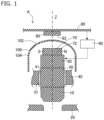
- FIG. 1 is a schematic cross-sectional view illustrating an overview of an electrically operated valve A according to the first embodiment. It should be noted that, in FIG. 1 , in order to avoid complication of the drawing, a portion of the electrically operated valve A is omitted.
- the electrically operated valve A includes a valve body 10, a driver 30, a rotation shaft 50, a power source 60 for transmitting power to the rotation shaft 50, a permanent magnet member 70 that includes a permanent magnet 72, and an angle sensor 80 for detecting a rotation angle of the permanent magnet 72.
- the valve body 10 closes the flow path by contacting the valve seat 20, and opens the flow path by separating from the valve seat 20.
- the rotation shaft 50 is a member for rotating the driver 30 about the first axis Z.
- the rotation shaft 50 receives power from a power source 60 and rotates about the first axis Z.
- the rotation shaft 50 and the driver 30 are mechanically connected to each other. Accordingly, when the rotation shaft 50 rotates about the first axis Z, the driver 30 also rotates about the first axis Z.
- the rotation shaft 50 and the driver 30 may be integrally formed or may be separately formed.
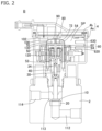
- FIG. 2 is a schematic cross-sectional view of the electrically operated valve B according to the second embodiment.
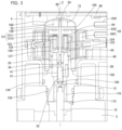
- FIG. 3 is a schematic enlarged cross-sectional view of a portion of the electrically operated valve B according to the second embodiment.
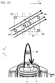
- FIG. 4 is a further enlarged view of a portion of FIG. 3 .
- the electrically operated valve B includes a power source 60 and a power transmission mechanism 120.
- the power source 60 includes a stator member 62 that includes a coil 620 and a rotor member 64.
- a pulse signal is input to the coil 620 from an electric wire 630 connected to the power source. Then, when a pulse signal is input to the coil 620, the rotor member 64 rotates by a rotation angle corresponding to the number of pulses of the pulse signal. That is, in the example illustrated in FIG. 2 , the stator member 62 and the rotor member 64 constitute a stepping motor.
- the power transmission mechanism 120 is a member for connecting the rotor member 64 and the rotation shaft 50 so as to enable power transmission.
- the power transmission mechanism 120 includes a plurality of gears.
- the power transmission mechanism 120 may include a planetary gear mechanism. Details of the planetary gear mechanism will be described later.
- the electrically operated valve B includes a housing member 4.
- An accommodation space SP (for example, a liquid-tight closed space) is formed in the housing member 4, and the above-described stator member 62, the can 100, the control substrate 90, and the like are accommodated in the accommodation space SP.
- the rotation shaft 50 rotates the driver 30.
- the second end 52 (that is, a shaft-side engagement member) of the rotation shaft 50 and the upper end 34 (that is, the driver-side engagement member) of the driver 30 are mechanically connected to each other so as not to be capable of rotation relative to each other.
- the second end 52 of the rotation shaft 50 and the upper end 34 of the driver 30 are movable relative to each other along the first axis Z. Accordingly, the rotation shaft 50 can move the driver 30 up and down without changing the vertical position of the rotation shaft 50 itself.
- the permanent magnet member 70 is disposed at the first end 54 of the rotation shaft 50.
- the position of the rotation shaft 50 in the vertical direction is not changed by the rotation operation of the rotation shaft 50. Accordingly, the position of the permanent magnet member 70 in the vertical direction, as well, is also not changed by the rotation operation of the rotation shaft 50. As a result, the distance between the permanent magnet member 70 and the angle sensor 80 is kept constant during the operation of the electrically operated valve B.
- the rotation shaft 50 and the driver 30 are separate bodies, and the rotation shaft 50 and the driver 30 are movable relative to each other along the first axis Z, it is possible to maintain a constant distance between the permanent magnet member 70 disposed on the rotation shaft 50 and the angle sensor 80. As a result, the accuracy of the detection of the rotation angle of the permanent magnet 72 by the angle sensor 80 is improved. In cases where the rotation shaft 50 and the permanent magnet 72 move up and down along with the vertical movement of the driver 30, there is a risk that the detection accuracy of the rotation angle of the permanent magnet 72 by the angle sensor 80 may be lowered.
- the second embodiment is innovative in that the rotation shaft 50 and the permanent magnet 72 are prevented from moving up and down even when the driver 30 moves vertically.
- the material of the partition member 130 will be described.
- the partition member 130 of the present embodiment is made of, for example, a resin (e.g., polyphenylene sulfide (PPS)).
- the partition member 130 may be formed of a soft magnetic material.
- the soft magnetic material include iron, silicon steel, a resin having magnetism, and the like.
- the member for partitioning the inside of the can into the upper space and the lower space is made of a soft magnetic material, whereby interference between the magnetism of the permanent magnet member 70 and other magnetism, for example, the magnetism of the rotor member 64, can be prevented.
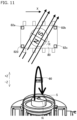
- each planetary gear 122 is rotatably supported by a shaft 124 that is supported by a carrier 123.
- the outer teeth of each planetary gear 122 mesh with an annular ring gear 125 (internal tooth fixed gear).
- the planetary gear 122 also meshes with an annular second ring gear 127 (an internal tooth movable gear).
- the second ring gear 127 functions as an output gear fixed to the rotation shaft 50.
- an output gear different from the second ring gear 127 may be fixed to the rotation shaft 50, and power from the second ring gear 127 may be transmitted to the rotation shaft 50 via the output gear.
- fixing of the rotation shaft 50 to the output gear may be performed by press-fitting the rotation shaft 50 to the output gear.
- the above-described gear configuration (the sun gear, planetary gear, internal tooth fixed gear, and internal tooth movable gear) constitutes a so-called eccentric planetary gear mechanism.
- a reduction gear using an eccentric planetary gear mechanism by setting the number of teeth of the second ring gear 127 to be slightly different from the number of teeth of the ring gear 125, the rotational speed of the sun gear 1212 can be reduced at a large reduction gear ratio and transmitted to the second ring gear 127.
- an eccentric planetary gear mechanism is employed as the power transmission mechanism 120.
- any power transmission mechanism can be employed as the power transmission mechanism between the rotor member 64 and the rotation shaft 50.
- a planetary gear mechanism other than the eccentric planetary gear mechanism may be utilized.
- the rotation shaft 50 includes a first end 54 and a second end 52.
- the rotation shaft 50 includes a rotation shaft body having a first end 54 and a shaft-side engagement member having a second end 52.
- the rotation shaft main body and the shaft-side engagement member are fixed to each other by, for example, welding or the like.
- the shaft-side engagement member engages with the driver-side engagement member formed by the upper end portion 34 of the driver 30 so as not to be rotatable relative to the driver-side engagement member while also being movable relative to the driver-side engagement member along the first axis Z direction.
- An external thread 31 is provided on the outer peripheral surface of the driver 30.
- the external thread 31 is screwed to an internal thread 41 provided on a guide member 40 for guiding the driver. Accordingly, when the rotation shaft 50 and the driver 30 rotate about the first axis Z, the driver 30 moves up and down while being guided by the guide member 40.
- the rotation shaft 50 is rotatably supported by a shaft receiving member such as the sun gear 1212 or the guide member 40, and cannot move in the first axis Z direction.
- the lower end 32 of the driver 30 is rotatably connected to the upper end 12 of the valve body 10 via a ball 160 or the like.
- a ball 160 or the like In the example illustrated in FIG. 3 , when the driver 30 moves downward while rotating about the first axis Z, the valve body 10 moves downward without rotating about the first axis Z.
- the driver 30 moves upward while rotating about the first axis Z, the valve body 10 moves upward without rotating about the first axis Z.
- the downward movement of the valve body 10 is performed as a result of the valve body 10 being pushed by the driver 30.
- the upward movement of the valve body 10 is performed by pushing the valve body 10 upward by a spring member 170 such as a coil spring while the driver 30 is moving upward. That is, in the example illustrated in FIG. 3 , the valve body 10 is constantly urged upward by the spring member 170 disposed between the spring bearing member 172 and the valve body 10.
- the valve body 10 and the driver 30 may be connected by a rotary joint, such as a ball joint, so that they cannot move relative to each other in a direction along the first axis Z. In this case, the spring member 170 may be omitted.
- the electrically operated valve B may include a computing device that converts the angle data output from the angle sensor 80 into position data of the valve body 10 in the direction along the first axis Z; that is, the opening degree data for the valve.
- the rotation shaft 50 and the permanent magnet 72 do not move up and down with respect to the angle sensor 80.
- the distance between the permanent magnet 72 and the angle sensor 80 is maintained at a constant distance during the operation of the electrically operated valve B. Accordingly, in the second embodiment, it is possible to accurately calculate the rotation angle of the permanent magnet 72 and the position of the valve body 10 along the first axis Z using the angle sensor 80.
- the holder 150 is disposed in the concave portion of the lower base member 2.
- a first seal member 152 such as an O-ring is disposed between the holder 150 and the lower base member 2.
- the holder 150 defines an internal space in which the upper end portion 12 of the valve body 10 can move. Accordingly, the holder 150 has a function of accommodating the upper end portion 12 of the valve body 10 in addition to a sealing function of preventing the liquid from entering the space in which the stator member 62 and the like are disposed.
- the holder 150 may have a function of supporting at least one of the cylindrical support member 126 or the guide member 40.
- each configuration of the electrically operated valve B in the second embodiment may be adopted in the electrically operated valve A of the first embodiment illustrated in FIG. 1 , as well.
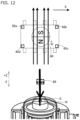
- the leaf spring 182 is disposed between the partition member 130 (the bearing member) and the permanent magnet member 70.
- the leaf spring 182 biases the permanent magnet member 70 toward the end wall 102 of the can 100.
- the partition member 130 bearing member
- the leaf spring 182 urges the permanent magnet member 70 against the end wall 102 even when the partition member can move up and down with respect to the can 100, the vertical position of the permanent magnet member 70 is preferably maintained.
- the rotation shaft 50a rotates.
- the rotation shaft 50a and the driver 30 are integrally formed as one member, or are integrally fixed to each other.
- an external thread 31 is provided on the outer peripheral surface of the driver 30, and the external thread 31 is screwed to an internal thread 41 provided on the guide member 40 for guiding the driver.
- the permanent magnet 72 has a north pole and a south pole in a top view.
- the number of north poles of the permanent magnet 72 is 1 and the number of south poles of the permanent magnet 72 is 1.
- the number of north poles of the permanent magnet and the number of south poles of the permanent magnet may be two or more, respectively, in the top view.
- the permanent magnet 72 includes a north pole and a south pole interface 78, and this interface 78 is a plane perpendicular to the first axis Z, passing through the first axis Z coinciding with the central axis of the rotation shaft (50; 50a).
- the angle sensor 80 is disposed above the permanent magnet 72. In the example illustrated in FIG. 9 , the angle sensor 80 is located on an extension of the rotation shaft (50; 50a); that is, on the first axis Z.
- the angle sensor 80 includes at least one magnetic detection element 82 (for example, a Hall element, a magnetoresistive element, or the like), and more preferably includes two or more or three or more magnetic detection elements.
- the angle sensor 80 includes four magnetic detection elements (82a to 82d).
- the magnetic detection elements (82a to 82d) may be elements for detecting a component of the magnetic flux in the direction along the first axis Z.
- the magnetic detection element 82a and the magnetic detection element 82d detect the magnetic flux component in the +Z direction
- the magnetic detection element 82b and the magnetic detection element 82c detect the magnetic flux component in the -Z direction.
- the interface 78 is perpendicular to the X-axis.
- the angle sensor 80 determines that the rotation angle of the permanent magnet 72 is, for example, 0 degrees.
- the angle sensor 80 can determine the inclination of the magnetic force line with respect to the X-axis; that is, the rotation angle of the permanent magnet 72.
- the angle sensor 80 can determine the inclination of the magnetic force line with respect to the X-axis; that is, the rotation angle of the permanent magnet 72.
- the magnetic detection element 82c and the magnetic detection element 82d detect the magnetic flux component in the +Z direction
- the magnetic detection element 82a and the magnetic detection element 82b detect the magnetic flux component in the -Z direction.
- the magnitude of the magnetic flux detected by the magnetic detection element 82a and the magnetic detection element 82c increases, and the magnitude of the magnetic flux detected by the magnetic detection element 82b and the magnetic detection element 82d decreases.
- the angle sensor 80 can determine the inclination of the magnetic force line with respect to the X-axis; that is, the rotation angle of the permanent magnet 72.
- the angle sensor 80 can detect the inclination of the permanent magnet 72 with respect to the X-axis; that is, the absolute rotation angle of the permanent magnet 72. Put differently, even when the permanent magnet 72 does not rotate, the angle sensor 80 can calculate the inclination (that is, the rotation angle) of the permanent magnet 72 with respect to the X-axis. The calculation of the rotation angle is performed based on, for example, the direction of the magnetic flux passing through at least three of the magnetic detection elements 82 and the magnitude of the magnetic flux passing through at least three of the magnetic detection elements 82.
- the electrically operated valves B and C include a stator member 62 having a coil 620 and a rotor member 64 as described in the second or third embodiment.
- the rotation angle of the rotor member 64 and the position of the valve body 10 proportional to the rotation angle of the rotor member 64 are proportional to the number of input pulses input to the coil 620. Accordingly, by monitoring the number of input pulses input to the coil 620, it is possible to calculate the position of the valve body 10 (that is, the height from the valve seat 20).
- the position of the valve body 10 (that is, the height from the valve seat 20) is also proportional to the rotation angle of the permanent magnet 72. Accordingly, by monitoring the rotation angle of the permanent magnet 72, it is possible to calculate the position of the valve body 10 (that is, the height from the valve seat 20).
- the position of the valve body 10 calculated from the number of pulses input to the coil 620 coincides with the position of the valve body 10 calculated from the rotation angle of the permanent magnet 72. Accordingly, when the position of the valve body 10 calculated from the number of input pulses to the coil 620 and the position of the valve body 10 calculated from the rotation angle of the permanent magnet 72 are different from each other, the computing device 200 determines that there is some abnormality in the electrically operated valves B and C. That is, the electrically operated valves B and C (electrically operated valve systems) have a self-diagnostic function for detecting the presence or absence of abnormalities in their own operation.
- the position of the valve body 10 and the rotation angle of the rotation shaft 50 are proportional to each other
- the position of the valve body 10 and the rotation angle of the permanent magnet 72 are proportional to each other
- the position of the valve body 10 and the rotation angle of the output gear are proportional to each other. Accordingly, in the present specification, calculating the position of the valve body 10 and calculating the rotation angle of the rotation shaft 50 are equivalent, calculating the position of the valve body 10 and calculating the rotation angle of the permanent magnet 72 are equivalent, and calculating the position of the valve body 10 and calculating the rotation angle of the output gear are equivalent.
- the storage device 202 of the computing device 200 stores a first valve body position calculation program for calculating the position ⁇ of the valve body 10 based on the rotation angle data of the permanent magnet.
- the position ⁇ of the valve body 10 includes a physical quantity proportional to the position of the valve body 10, such as the rotation angle of the rotation shaft 50, the rotation angle of the permanent magnet, or the rotation angle of the output gear, in addition to the position of the valve body 10 itself.
- the computing device 200 calculates the position ⁇ of the valve body 10 from the rotation angle data of the permanent magnet by executing the first valve body position calculation program.
- the storage device 202 of the computing device 200 stores a determination program for comparing the position ⁇ of the valve body and the position ⁇ of the valve body to determine whether or not there is an operation abnormality of the electrically operated valve (the electrically operated valve system) based on this comparison result.
- the computing device 200 determines whether or not there is an abnormality in the operation of the electrically operated valve (the electrically operated valve system) by executing the determination program. For example, the computing device 200 executes the determination program to determine whether or not the difference between the position ⁇ of the valve body and the position ⁇ of the valve body is equal to or larger than a preset threshold value.
- the computing device 200 may store the determination result in the storage device 202 by executing the determination program.
- the abnormal operation of the electrically operated valve is stored in the storage device 202 as log data.
- the first valve body position calculation, the second valve body position calculation, and the determination program in the above-described computing device 200 may be performed by an electronic circuit in a hardware manner.
- the electronic circuit or the hardware processor of the computing device 200 may be mounted on the control substrate 90.
- the configuration of the computing device 200 and the like described with reference to FIG. 13 may be employed in the electrically-operated valve B of the second embodiment or the electrically-operated valve C of the third embodiment.
- the configuration of the computing device 200 and the like described with reference to FIG. 13 may be utilized in the electrically-operated valve A of the embodiment illustrated in FIG. 1 .
- the angle sensor includes a plurality of magnetic elements configured to detect a component of a magnetic flux in a direction along the first axis.
- An electrically operated valve comprising:
Landscapes
- Engineering & Computer Science (AREA)
- General Engineering & Computer Science (AREA)
- Mechanical Engineering (AREA)
- Physics & Mathematics (AREA)
- General Physics & Mathematics (AREA)
- Indication Of The Valve Opening Or Closing Status (AREA)
- Electrically Driven Valve-Operating Means (AREA)
- Measurement Of Length, Angles, Or The Like Using Electric Or Magnetic Means (AREA)
Applications Claiming Priority (4)
| Application Number | Priority Date | Filing Date | Title |
|---|---|---|---|
| JP2017029192A JP6741611B2 (ja) | 2017-02-20 | 2017-02-20 | 電動弁 |
| PCT/JP2018/002925 WO2018150863A1 (fr) | 2017-02-20 | 2018-01-30 | Électrovanne |
| EP23175575.2A EP4235106B1 (fr) | 2017-02-20 | 2018-01-30 | Électrovanne |
| EP18753791.5A EP3584479B1 (fr) | 2017-02-20 | 2018-01-30 | Électrovanne |
Related Parent Applications (3)
| Application Number | Title | Priority Date | Filing Date |
|---|---|---|---|
| EP18753791.5A Division EP3584479B1 (fr) | 2017-02-20 | 2018-01-30 | Électrovanne |
| EP23175575.2A Division EP4235106B1 (fr) | 2017-02-20 | 2018-01-30 | Électrovanne |
| EP23175575.2A Division-Into EP4235106B1 (fr) | 2017-02-20 | 2018-01-30 | Électrovanne |
Publications (2)
| Publication Number | Publication Date |
|---|---|
| EP4579110A2 true EP4579110A2 (fr) | 2025-07-02 |
| EP4579110A3 EP4579110A3 (fr) | 2025-10-08 |
Family
ID=63169251
Family Applications (3)
| Application Number | Title | Priority Date | Filing Date |
|---|---|---|---|
| EP23175575.2A Active EP4235106B1 (fr) | 2017-02-20 | 2018-01-30 | Électrovanne |
| EP18753791.5A Active EP3584479B1 (fr) | 2017-02-20 | 2018-01-30 | Électrovanne |
| EP25177406.3A Pending EP4579110A3 (fr) | 2017-02-20 | 2018-01-30 | Soupape électrique |
Family Applications Before (2)
| Application Number | Title | Priority Date | Filing Date |
|---|---|---|---|
| EP23175575.2A Active EP4235106B1 (fr) | 2017-02-20 | 2018-01-30 | Électrovanne |
| EP18753791.5A Active EP3584479B1 (fr) | 2017-02-20 | 2018-01-30 | Électrovanne |
Country Status (6)
| Country | Link |
|---|---|
| US (1) | US10982792B2 (fr) |
| EP (3) | EP4235106B1 (fr) |
| JP (1) | JP6741611B2 (fr) |
| KR (1) | KR102220968B1 (fr) |
| CN (2) | CN110325775B (fr) |
| WO (1) | WO2018150863A1 (fr) |
Families Citing this family (25)
| Publication number | Priority date | Publication date | Assignee | Title |
|---|---|---|---|---|
| US10855158B2 (en) * | 2018-04-19 | 2020-12-01 | Watasensor, Inc. | Magnetic power generation |
| WO2020181922A1 (fr) * | 2019-03-13 | 2020-09-17 | 浙江盾安人工环境股份有限公司 | Vanne de détente électronique et système de réfrigération |
| EP3951226B1 (fr) * | 2019-03-29 | 2025-04-23 | Fujikoki Corporation | Électrovanne |
| FR3097610B1 (fr) | 2019-06-20 | 2021-08-06 | Moving Magnet Tech | Vanne de réglage compacte |
| JP7462282B2 (ja) * | 2019-08-22 | 2024-04-05 | 株式会社テージーケー | 電動弁 |
| CN110792834B (zh) * | 2019-10-15 | 2021-07-06 | 陕西科技大学 | 一种可实现误差补偿控制的电动阀门及其工作方法 |
| CN113028072A (zh) * | 2019-12-25 | 2021-06-25 | 盾安环境技术有限公司 | 电子膨胀阀 |
| IT202000014632A1 (it) * | 2020-06-18 | 2021-12-18 | Cavagna Group Spa | Gruppo valvola per recipienti in pressione |
| CN113833896B (zh) * | 2020-06-24 | 2025-12-30 | 浙江三花汽车零部件有限公司 | 电动球阀 |
| CN113833895A (zh) * | 2020-06-24 | 2021-12-24 | 浙江三花汽车零部件有限公司 | 一种电动球阀 |
| JP7609417B2 (ja) | 2021-03-15 | 2025-01-07 | 株式会社テージーケー | 電動弁制御装置 |
| JP7560121B2 (ja) * | 2021-06-17 | 2024-10-02 | 株式会社テージーケー | 電動弁制御装置、調整装置、電動弁制御プログラムおよび調整プログラム |
| KR102812991B1 (ko) | 2021-06-29 | 2025-05-27 | 가부시기가이샤 후지고오키 | 전동 밸브 |
| JP7653707B2 (ja) | 2021-08-24 | 2025-03-31 | 株式会社テージーケー | 電動弁制御装置、調整装置、電動弁制御プログラム及び調整プログラム |
| JP7555594B2 (ja) | 2021-09-15 | 2024-09-25 | 株式会社不二工機 | 電動弁 |
| JP2023057584A (ja) * | 2021-10-12 | 2023-04-24 | 株式会社テージーケー | 電動弁装置、情報処理装置および情報処理プログラム |
| JP7362180B1 (ja) | 2022-02-04 | 2023-10-17 | 株式会社不二工機 | 電動弁制御装置および電動弁装置 |
| CN116733980A (zh) * | 2022-03-03 | 2023-09-12 | 浙江三花智能控制股份有限公司 | 一种阀装置 |
| WO2023203967A1 (fr) * | 2022-04-21 | 2023-10-26 | 株式会社不二工機 | Soupape électrique |
| CN115750799A (zh) * | 2022-11-18 | 2023-03-07 | 嘉兴科奥电磁技术有限公司 | 电子膨胀阀 |
| TWI841382B (zh) * | 2023-05-10 | 2024-05-01 | 微程式資訊股份有限公司 | 閥門維修警示裝置 |
| JPWO2024257390A1 (fr) * | 2023-06-16 | 2024-12-19 | ||
| JP2025024620A (ja) * | 2023-08-07 | 2025-02-20 | 日本サーモスタット株式会社 | 電動弁 |
| DE102023207867A1 (de) * | 2023-08-16 | 2025-02-20 | Volkswagen Aktiengesellschaft | Magnetische Lagebestimmung einer Kühlmittelventilnadel |
| DE102024113992A1 (de) * | 2024-05-17 | 2025-11-20 | Bürkert Werke GmbH & Co. KG | Verfahren zum Feststellen einer Winkelposition eines Signalgebers, Winkelerfassungssystem und Ventil |
Citations (3)
| Publication number | Priority date | Publication date | Assignee | Title |
|---|---|---|---|---|
| JP2001012633A (ja) | 1999-06-29 | 2001-01-16 | Fuji Koki Corp | 電動弁の弁開度検出装置および電動弁の弁開度制御装置 |
| JP2014161152A (ja) | 2013-02-19 | 2014-09-04 | Fuji Koki Corp | ステッピングモータ及びそれを用いた電動弁 |
| WO2016091941A1 (fr) | 2014-12-09 | 2016-06-16 | Mmt Sa | Vanne de dosage adaptée aux hautes pressions |
Family Cites Families (29)
| Publication number | Priority date | Publication date | Assignee | Title |
|---|---|---|---|---|
| JPH05256544A (ja) * | 1992-03-12 | 1993-10-05 | Toshiba Corp | 冷凍機の電子膨脹弁制御装置 |
| JPH08326952A (ja) * | 1995-06-05 | 1996-12-10 | Nippondenso Co Ltd | 流量制御弁の動作不良診断装置 |
| JP3937029B2 (ja) * | 1999-03-26 | 2007-06-27 | 株式会社鷺宮製作所 | 電動弁 |
| US6460567B1 (en) * | 1999-11-24 | 2002-10-08 | Hansen Technologies Corpporation | Sealed motor driven valve |
| JP4391065B2 (ja) | 2002-08-23 | 2009-12-24 | 愛三工業株式会社 | スロットル開度検出装置 |
| US7066189B2 (en) | 2002-12-20 | 2006-06-27 | Control Components, Inc. | Predictive maintenance and initialization system for a digital servovalve |
| JP3983722B2 (ja) | 2003-08-04 | 2007-09-26 | 三菱電機株式会社 | エンジン用吸気制御装置 |
| US7988363B2 (en) | 2005-02-22 | 2011-08-02 | Ntn Corporation | Bearing with rotation detection device |
| JP4704065B2 (ja) | 2005-02-22 | 2011-06-15 | Ntn株式会社 | 回転検出装置付き軸受 |
| JP4749784B2 (ja) * | 2005-07-19 | 2011-08-17 | 株式会社不二工機 | 電動弁 |
| JP2007113626A (ja) * | 2005-10-19 | 2007-05-10 | Yamatake Corp | 電動アクチュエータ |
| JP2008101765A (ja) * | 2006-09-20 | 2008-05-01 | Fuji Koki Corp | 電動弁 |
| DE102007018758B4 (de) | 2007-01-08 | 2019-05-29 | Asm Automation Sensorik Messtechnik Gmbh | Winkelsensor |
| JP2008215942A (ja) | 2007-03-01 | 2008-09-18 | Nsk Ltd | トルクセンサ及び電動式パワーステアリング装置 |
| JP4385071B2 (ja) | 2007-12-18 | 2009-12-16 | 三菱電機株式会社 | 非接触式回転角度検出装置及びその製造方法 |
| JP5301864B2 (ja) * | 2008-03-31 | 2013-09-25 | 株式会社ミクニ | 回転位置センサ |
| JP5344375B2 (ja) * | 2009-09-30 | 2013-11-20 | 日本精機株式会社 | 回転角度検出装置 |
| JP5875777B2 (ja) | 2011-03-31 | 2016-03-02 | 株式会社不二工機 | 電動弁 |
| US9464577B2 (en) * | 2011-09-19 | 2016-10-11 | Walbro Llc | Rotary position sensor with buffer |
| GB2505226A (en) * | 2012-08-23 | 2014-02-26 | Melexis Technologies Nv | Arrangement, method and sensor for measuring an absolute angular position using a multi-pole magnet |
| DE102012220139B4 (de) | 2012-11-06 | 2026-04-30 | Robert Bosch Gmbh | Magnetische Messanordnung und korrespondierende Sensoranordnung zur Bewegungserfassung eines bewegten Bauteils |
| JP6180197B2 (ja) * | 2013-06-17 | 2017-08-16 | 株式会社ケーヒン | 回転角度検出装置 |
| JP6648022B2 (ja) * | 2013-09-11 | 2020-02-14 | ボーンズ、インコーポレイテッド | 高分解能の多回転センサに関連するデバイスおよび方法 |
| CN103791140A (zh) * | 2014-01-24 | 2014-05-14 | 南通神华电气有限公司 | 一种电动阀门 |
| JP6246325B2 (ja) * | 2014-03-19 | 2017-12-13 | 三菱電機株式会社 | 電動モータおよびこれを用いた電動パワーステアリング装置 |
| CN203770807U (zh) * | 2014-04-09 | 2014-08-13 | 黄建斌 | 阀门执行器 |
| JP2016090499A (ja) * | 2014-11-10 | 2016-05-23 | いすゞ自動車株式会社 | バルブ開度計測方法、並びにバルブ開度計測プログラム、及び車両用のシミュレータ |
| DE112016001508A5 (de) | 2015-03-30 | 2018-01-04 | Schaeffler Technologies AG & Co. KG | Antriebseinheit, insbesondere eines Getriebeaktuators |
| JP6670230B2 (ja) * | 2016-12-22 | 2020-03-18 | 株式会社Soken | トルク検出装置 |
-
2017
- 2017-02-20 JP JP2017029192A patent/JP6741611B2/ja active Active
-
2018
- 2018-01-30 CN CN201880012990.7A patent/CN110325775B/zh active Active
- 2018-01-30 EP EP23175575.2A patent/EP4235106B1/fr active Active
- 2018-01-30 CN CN202011354091.0A patent/CN112431960B/zh active Active
- 2018-01-30 KR KR1020197023112A patent/KR102220968B1/ko active Active
- 2018-01-30 EP EP18753791.5A patent/EP3584479B1/fr active Active
- 2018-01-30 US US16/482,030 patent/US10982792B2/en active Active
- 2018-01-30 WO PCT/JP2018/002925 patent/WO2018150863A1/fr not_active Ceased
- 2018-01-30 EP EP25177406.3A patent/EP4579110A3/fr active Pending
Patent Citations (3)
| Publication number | Priority date | Publication date | Assignee | Title |
|---|---|---|---|---|
| JP2001012633A (ja) | 1999-06-29 | 2001-01-16 | Fuji Koki Corp | 電動弁の弁開度検出装置および電動弁の弁開度制御装置 |
| JP2014161152A (ja) | 2013-02-19 | 2014-09-04 | Fuji Koki Corp | ステッピングモータ及びそれを用いた電動弁 |
| WO2016091941A1 (fr) | 2014-12-09 | 2016-06-16 | Mmt Sa | Vanne de dosage adaptée aux hautes pressions |
Also Published As
| Publication number | Publication date |
|---|---|
| US10982792B2 (en) | 2021-04-20 |
| WO2018150863A1 (fr) | 2018-08-23 |
| JP6741611B2 (ja) | 2020-08-19 |
| CN110325775B (zh) | 2020-12-22 |
| EP3584479A4 (fr) | 2020-12-02 |
| JP2018135908A (ja) | 2018-08-30 |
| EP4235106A2 (fr) | 2023-08-30 |
| EP4235106A3 (fr) | 2023-09-27 |
| EP3584479B1 (fr) | 2023-07-05 |
| KR102220968B1 (ko) | 2021-02-26 |
| EP3584479A1 (fr) | 2019-12-25 |
| EP4579110A3 (fr) | 2025-10-08 |
| US20190353271A1 (en) | 2019-11-21 |
| KR20190105044A (ko) | 2019-09-11 |
| EP4235106B1 (fr) | 2025-07-09 |
| CN110325775A (zh) | 2019-10-11 |
| CN112431960B (zh) | 2022-11-18 |
| CN112431960A (zh) | 2021-03-02 |
Similar Documents
| Publication | Publication Date | Title |
|---|---|---|
| US10982792B2 (en) | Electric valve | |
| EP3604877B1 (fr) | Vanne actionnée électriquement | |
| US7261012B2 (en) | Gear drive unit with speed measurement | |
| EP3392538B1 (fr) | Soupape à commande électrique | |
| US7292028B2 (en) | Apparatus for sensing the absolute-value angle of a shaft | |
| EP2103910B1 (fr) | Détecteur d'angle de rotation | |
| US7750625B2 (en) | Linear position sensor | |
| CN102414539A (zh) | 角度传感器 | |
| US11525663B2 (en) | Rotation angle measurement system | |
| JP7262137B2 (ja) | 電動弁 | |
| EP4538571A1 (fr) | Dispositif de commande de soupape électrique et dispositif de soupape électrique | |
| JP6947445B2 (ja) | 電動弁 | |
| EP1783461B1 (fr) | Palier avec capteur d'angle absolu | |
| EP3239666A1 (fr) | Ensemble de lecture électronique destiné à un débitmètre | |
| JP2022069019A (ja) | 検出装置 | |
| JPH04109369U (ja) | 回転子軸の回転方向検知装置 |
Legal Events
| Date | Code | Title | Description |
|---|---|---|---|
| PUAI | Public reference made under article 153(3) epc to a published international application that has entered the european phase |
Free format text: ORIGINAL CODE: 0009012 |
|
| STAA | Information on the status of an ep patent application or granted ep patent |
Free format text: STATUS: THE APPLICATION HAS BEEN PUBLISHED |
|
| AC | Divisional application: reference to earlier application |
Ref document number: 3584479 Country of ref document: EP Kind code of ref document: P Ref document number: 4235106 Country of ref document: EP Kind code of ref document: P |
|
| AK | Designated contracting states |
Kind code of ref document: A2 Designated state(s): AL AT BE BG CH CY CZ DE DK EE ES FI FR GB GR HR HU IE IS IT LI LT LU LV MC MK MT NL NO PL PT RO RS SE SI SK SM TR |
|
| PUAL | Search report despatched |
Free format text: ORIGINAL CODE: 0009013 |
|
| AK | Designated contracting states |
Kind code of ref document: A3 Designated state(s): AL AT BE BG CH CY CZ DE DK EE ES FI FR GB GR HR HU IE IS IT LI LT LU LV MC MK MT NL NO PL PT RO RS SE SI SK SM TR |
|
| RIC1 | Information provided on ipc code assigned before grant |
Ipc: F16K 37/00 20060101AFI20250904BHEP Ipc: F16K 31/04 20060101ALI20250904BHEP Ipc: F16K 31/50 20060101ALI20250904BHEP Ipc: G01D 5/14 20060101ALI20250904BHEP |
|
| STAA | Information on the status of an ep patent application or granted ep patent |
Free format text: STATUS: REQUEST FOR EXAMINATION WAS MADE |
|
| 17P | Request for examination filed |
Effective date: 20251020 |
|
| TPAC | Observations filed by third parties |
Free format text: ORIGINAL CODE: EPIDOSNTIPA |