EP2103910B1 - Détecteur d'angle de rotation - Google Patents
Détecteur d'angle de rotation Download PDFInfo
- Publication number
- EP2103910B1 EP2103910B1 EP07850620.1A EP07850620A EP2103910B1 EP 2103910 B1 EP2103910 B1 EP 2103910B1 EP 07850620 A EP07850620 A EP 07850620A EP 2103910 B1 EP2103910 B1 EP 2103910B1
- Authority
- EP
- European Patent Office
- Prior art keywords
- magnet
- rotation angle
- angle detector
- designed
- rotation
- Prior art date
- Legal status (The legal status is an assumption and is not a legal conclusion. Google has not performed a legal analysis and makes no representation as to the accuracy of the status listed.)
- Active
Links
- 238000001514 detection method Methods 0.000 claims description 17
- 230000004907 flux Effects 0.000 claims description 15
- 230000003247 decreasing effect Effects 0.000 claims description 6
- 239000000758 substrate Substances 0.000 description 20
- 125000006850 spacer group Chemical group 0.000 description 6
- 238000004806 packaging method and process Methods 0.000 description 5
- 230000005355 Hall effect Effects 0.000 description 2
- 230000015572 biosynthetic process Effects 0.000 description 2
- 239000000126 substance Substances 0.000 description 2
- 238000001125 extrusion Methods 0.000 description 1
- 230000005389 magnetism Effects 0.000 description 1
- 238000000034 method Methods 0.000 description 1
- 230000000149 penetrating effect Effects 0.000 description 1
- 230000035945 sensitivity Effects 0.000 description 1
Images


Classifications
-
- G—PHYSICS
- G01—MEASURING; TESTING
- G01D—MEASURING NOT SPECIALLY ADAPTED FOR A SPECIFIC VARIABLE; ARRANGEMENTS FOR MEASURING TWO OR MORE VARIABLES NOT COVERED IN A SINGLE OTHER SUBCLASS; TARIFF METERING APPARATUS; MEASURING OR TESTING NOT OTHERWISE PROVIDED FOR
- G01D5/00—Mechanical means for transferring the output of a sensing member; Means for converting the output of a sensing member to another variable where the form or nature of the sensing member does not constrain the means for converting; Transducers not specially adapted for a specific variable
- G01D5/12—Mechanical means for transferring the output of a sensing member; Means for converting the output of a sensing member to another variable where the form or nature of the sensing member does not constrain the means for converting; Transducers not specially adapted for a specific variable using electric or magnetic means
- G01D5/14—Mechanical means for transferring the output of a sensing member; Means for converting the output of a sensing member to another variable where the form or nature of the sensing member does not constrain the means for converting; Transducers not specially adapted for a specific variable using electric or magnetic means influencing the magnitude of a current or voltage
- G01D5/142—Mechanical means for transferring the output of a sensing member; Means for converting the output of a sensing member to another variable where the form or nature of the sensing member does not constrain the means for converting; Transducers not specially adapted for a specific variable using electric or magnetic means influencing the magnitude of a current or voltage using Hall-effect devices
- G01D5/145—Mechanical means for transferring the output of a sensing member; Means for converting the output of a sensing member to another variable where the form or nature of the sensing member does not constrain the means for converting; Transducers not specially adapted for a specific variable using electric or magnetic means influencing the magnitude of a current or voltage using Hall-effect devices influenced by the relative movement between the Hall device and magnetic fields
Definitions
- the present invention relates to a rotation angle detector to be attached to a rotation body and then to be made use for detecting a rotation angle of such the rotation body.
- a rotation angle detector for detecting such as a shaft that is being rotated or the like (Japanese Patent Application Publication No. 2003-075108 (claims 2 to 4, FIG. 4 and FIG. 5 ) for example).
- a magnet therein to be as a disk shape and then to be supported by an axis of rotation therein.
- the magnet to be configured as rotatable in a predetermined direction with such the axis of rotation as a center therefor.
- the rotation angle detector further comprises magnetic sensors as two units therefor.
- such the magnetic sensors as two units are Hall elements, and then there is designed the same to be arranged for having an angle as approximately ninety degrees for between a straight line, that passes through a center of such the disk and through one of the magnetic sensors, and another straight line, that passes through the center of such the disk and through the other one of the magnetic sensors. Furthermore, there is designed each of such the magnetic sensors to be arranged at directly under a circumference of such the magnet respectively.
- the magnet to be magnetized in a radial direction thereof, and then there is designed each of the Hall elements to be arranged at edge parts on the circumference of such the magnet for improving a sensitivity of each of the sensors.
- it is able to maintain an accuracy of the detection therefor only in a case where a relationship of relative positions between the magnet and each of the Hall elements is not varied at all.
- the actual rotation angle detector there is a backlash in an axial direction of an axis for the rotation or in a radial direction thereof, and then thereby a relative distance between such the magnet and each of such the Hall elements is varied dynamically.
- each of such the Hall elements cannot help but detect a signal due to a movement of such the magnet that is not related to the rotation regarding the axis of the rotation thereof at all.
- FIG. 8 is a schematic plan view for showing such a rotation angle detector 5, wherein each of Hall elements 90 (91 and 92) is designed to be arranged respectively, with having an angle for therebetween as approximately ninety degrees in a vicinity of a periphery for a magnet 50.
- FIG. 9 is a view for exemplary showing a line of magnetic force 50A according to the magnet 50 at a state that such the rotation angle detector 5 is attached onto a steering shaft that is not shown in the figure with a relationship of dimensions as optimal for therebetween, via a shaft 55.
- each of such the Hall elements 90 (the Hall element as the 91 according to FIG. 9 ) on a substrate 70 that is designed to be arranged thereat and then to be fixed thereon as independent of the rotation of the magnet 50, for intersecting such the line of magnetic force 50A according thereto in a vicinity of a point part, that has a curvature as the maximum thereat, of such the magnet 50 that is designed to have a disk shape. Furthermore, there is designed to be detected a degree of magnitude for such the magnetic flux density thereof by making use of each of such the Hall elements 90.
- FIG. 10 shows a state that in a case where a backlash as a certain degree of magnitude thereof is allowed for between a stator therein and a rotor therein regarding a direction of a central axis line of such the rotor in the rotation angle detector 5, that is for improving the assembly easiness for such the rotation angle detector 5 as mentioned above, and then that the magnet 50 in such the rotation angle detector 5 as shown in FIG. 9 is shifted due to such the backlash comparing to each of the Hall elements 90 as a little amount toward the direction of the central axis line of the such the magnet 50.
- such the degree of magnitude to be shifted is the degree of magnitude to be shifted that is required for designing an improvement of the assembly easiness for such the rotation angle detector 5 as described above. And then in a case where such the rotation angle detector 5 becomes to be at such the state thereof, the line of magnetic force 50A according to the magnet 50 cannot help but become to be come apart from each of the Hall elements 90. Thus, it becomes clear that there becomes to be decreased excessively thereby a property of the detection by making use of each of such the Hall elements 90.
- the rotation angle detector as disclosed in the Japanese Patent Application Publication No. 2006-105827 for example.
- the rotation angle detector comprises a magnet as a ring shape, and then there is designed to be enhanced for the same to have a freedom as higher regarding a position of an attachment thereof for a steering in a motor vehicle, by penetrating such the magnet through a steering shaft in such the motor vehicle.
- a Hall element to be arranged in a vicinity of a point part that has a curvature as the maximum regarding a line of magnetic force according to such the magnet, that is for improving a property of a detection regarding such a sensor itself.
- FIG. 11 is a view for exemplary showing a line of magnetic force 60A according to a magnet 60 in a case where such a rotation angle detector 6 is attached onto a shaft that is not shown in the figure, with a relationship of dimensions as optimal for therebetween. Furthermore, according to the same figure, there is designed to be arranged a Hall element 90 in a vicinity of a point part of the line of magnetic force 60A according to the magnet 60 as a ring shape, and then there is designed to be detected a degree of magnitude for such the magnetic flux density thereof by making use of such the Hall element 90 on a substrate 80 that is designed to be arranged thereat and then to be fixed thereon as independent of the rotation of such the magnet 60.
- FIG. 12 shows a state that in a case where a backlash as a certain degree of magnitude thereof is allowed for between a stator in the rotation angle detector 6 and a rotor therein regarding a direction of a central axis line of such the rotor, and then that the magnet 60 in such the rotation angle detector 6 as shown in FIG. 11 is shifted due to such the backlash comparing to the Hall element 90 as a little amount toward the direction of the central axis line of the rotation of such the magnet 60.
- the degree of magnitude to be shifted is the degree of magnitude to be shifted that is required for designing an improvement of an assembly easiness for such the rotation angle detector 6 as described above.
- EP 1 024 267 A2 discloses an arrangement which includes a throttle flap held by a shaft, and arranged adjustable in a casing.
- a Hall effect angle sensor unit is arranged at the shaft, consisting of a movable unit, and a stationary unit.
- a gearing is arranged between the movable unit and a drive unit.
- the stationary unit consists of a first and a second stator ring segment, spaced apart by an extrusion, in which at least one Hall effect circuit is arranged.
- the movable unit consists of a toroidal magnet segment, spaced apart from the stator ring segments by an air gap, and held, jointly with a third stator ring segment in a cogged wheel segment of the gearing.
- WO 2006/115763 A2 discloses a position sensor comprising: a magnetic element having opposed rectilinear edges and having a cavity disposed therein; a flux concentrator at least partially disposed about a periphery of the magnetic element; and a magnetic field sensor positioned within the cavity.
- the magnetic polarity of the magnet with the flux concentrator runs perpendicular to the axis of rotation of the rotatable body containing the magnet.
- It is an object of the present invention is to provide a rotation angle detector, by which it becomes possible to measure a rotation angle of a steering shaft for a vehicle with a high accuracy even in a case where there may be an axial backlash or the like on an axis of rotation of the steering shaft for a vehicle.
- a rotation angle detector according to the present invention comprises the features of claim 1.
- the rotation angle detector of the present invention it becomes possible to measure the rotation angle of the measurable rotation body with higher accuracy at all times, even in the case where the backlash may be allowed up to a certain degree of magnitude in the direction of the central line of the rotation regarding the rotor or between the rotor, within which the magnet is provided, and the stator, within which the magnetic detecting element is provided, for designing a rotation angle detector that is improved with respect to easiness of the assembly.
- a rotation angle detector 1 regarding one embodiment according to the present invention will be described in detail below, with reference to the drawings. Moreover, according to such the description, there will be described in detail below regarding a case where there is designed to be attached such the rotation angle detector onto a steering shaft as a measurable rotation body regarding a steering device in a motor vehicle, and then there is designed to be detected a rotation angle of a steering wheel therein by making use thereof.
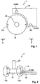
- such the rotation angle detector 1 regarding the one embodiment according to the present invention comprises as shown in FIG. 1 and in FIG. 2 : a magnet 10 as a disk shape; a shaft 20 that is designed to be provided as protruding therefrom at one side for a central part of the magnet 10; a substrate 30 that is designed to be fixed as independent of individual rotations of the magnet 10 and of the shaft 20; and Hall elements 40 as two units (41 and 42) (magnetic detecting elements), that are designed to be arranged on such the substrate, with having approximately ninety degrees for therebetween to a central axis line of the magnet 10, and with spacing a distance as equivalent to each other from such the central axis line of the magnet 10, at an outer side in a circumferential direction of such the magnet 10 as the disk shape.
- Hall elements 40 as two units (41 and 42) (magnetic detecting elements), that are designed to be arranged on such the substrate, with having approximately ninety degrees for therebetween to a central axis line of the magnet 10, and with spacing a distance
- a stator that is comprised of such as a packaging body or the like which is not shown in the figures.
- the magnet 10 and the shaft 20 to comprise a portion of a rotor or a whole thereof as not described in detail here.
- the rotor to be supported as rotatable by such the stator via a member for support that is not shown in the figures.
- a point part of the shaft 20 to be connected to the steering shaft and then to be rotated together as integral therewith, that is for detecting a rotation angle thereof by making use of the rotation angle detector 1.
- the magnet 10 to be formed at one point part in a circumferential direction thereof as one side in the direction of the central axis line of the rotation (a right side in FIG. 1 and an upper right side in FIG. 2 for example) is defined to be as a south pole and as the other side in the direction of the axis line thereof (the right side in FIG. 1 and a lower right side in FIG. 2 for example) is defined to be as a north pole. Still further, there is designed the same to be formed at the other point part in the circumferential direction thereof (the point part at the opposite side to the one point part in a direction of a diameter thereof) as one side in the direction of the axis line thereof (a left side in FIG. 1 and an upper left side in FIG.
- each of formation regions of the north pole therein and of the south pole therein is designed gradually toward a direction of a thickness of the magnet 10 (in the direction of the central axis line of the rotation of the magnet 10).
- the substrate 30 and the magnet 10 at an inside of the packaging body are designed to be housed to be made from a substance that is for shielding any magnetism from an outer side therefrom.
- the packaging body is designed for such the packaging body to be able to be attached onto a part for fixing, with making use of such as a bracket or the like as not shown in the figures, that is different from the position for the shaft 20 and from the position for the steering shaft that is designed to be connected thereto as well.
- the Hall elements 40 as the two units (41 and 42) as mentioned above, and then to be detected a variation of a magnetic flux density due to the rotation of the shaft 20 to be rotated as integral with the steering shaft as not shown in the figures, that is to say, due to the rotation of the magnet 10, by making use of each of such the Hall elements 40 (41 and 42) respectively.
- each of such the Hall elements 40 (41 and 42) for the magnet 10
- the other one of the Hall elements as the 42 that is designed to be arranged at an upper side of the magnet 10 as shown in FIG. 3 (a) , has a characteristic of the output therefrom that shows a sinusoidal waveform as shown in FIG. 3 (b) that is similar thereto. Still further, there is designed such the characteristic of the output from such the other one of the Hall elements as the 42 to be shifted a phase thereof as approximately ninety degrees from the characteristic of the output from the one of the Hall elements as the 41 as shown in FIG. 3 (b) , because of an aspect of the arrangements for each thereof on the substrate respectively.
- each of the outputs from the individual Hall elements as the 41 and the 42 to be as an X and a Y, that individually have the phases to be shifted as approximately ninety degrees to each other, it becomes able to obtain an output as a saw tooth shape by evaluating tan -1 (X / Y). And then thereby there is designed to be detected the rotation angle of the steering shaft with the accuracy as higher in a cycle as 360 degrees therefor.
- FIG. 2 is a view for exemplary showing the line of magnetic force 10A according to the magnet 10 in a case where such the rotation angle detector is attached onto a steering shaft in a motor vehicle that is not shown in the figure, with maintaining a state that a relationship of relative positions for between a rotor therein and a stator therein to be as optimal to each of there between.
- the one of the Hall elements as the 41 is designed to be arranged at a position on the line of magnetic force 10A according to the magnet 10 as the disk shape, that becomes to be parallel to the central axis line of the rotation of such the magnet 10, and that is optimal from a designing point of view. Moreover, there is designed to be detected the degree of magnitude of the magnetic flux density according thereto by making use of such the one of the Hall elements as the 41.
- FIG. 4 shows a state that in a case where a backlash as a certain degree of magnitude thereof is allowed, for improving the assembly easiness for such the rotation angle detector as mentioned above, for between the stator in the rotation angle detector 1 and the rotor therein regarding the direction of the central axis line of the rotation of such the rotor, and then that the magnet 10 in such the rotation angle detector 1 as shown in FIG. 2 is shifted due to such the backlash as a little amount in the direction of the central axis line of the rotation of the magnet 10 with respect to one of the Hall elements such as the 41.
- such degree of magnitude to be shifted is the degree of magnitude to be shifted that is required for designing an improvement of the assembly easiness for such the rotation angle detector 1. And then even there becomes to be at such the state thereof, regarding the line of magnetic force 10A according to the magnet 10 crossing the one of the Hall elements as the 41 how to cross there through, it is approximately equivalent to the case where the relationship of the relative positions for between the magnet 10 and the one of the Hall elements as the 41 as shown in FIG. 2 is at the state as the optimum to each of there between. Hence, it becomes clear that the property of the detection is almost not decreased by making use of such the one of the Hall elements as the 41.
- such a rotation angle detector 1' regarding the modified example according to the present invention comprises as shown in FIG. 5 and in FIG. 6 : a magnet 110 as a ring shape; a spacer 125 that is designed to be attached at an internal circumference of the magnet 110; a substrate 130 that is designed to be arranged and then to be fixed as independent of individual rotations of the magnet 110 and of the shaft as the Sh; and Hall elements 140 as two units (141 and 142) (magnetic detecting elements), that are designed to be arranged on such the substrate, with having approximately ninety degrees for therebetween to a central axis line of the magnet 110, and with spacing a distance as equivalent to each other from such the central axis line of the magnet 110, at an outer side in a circumferential direction of such the magnet 110.
- a stator that is comprised of such as a packaging body or the like that is not shown in the figures.
- the magnet 110 and the spacer 125 to comprise a portion of a rotor or a whole thereof as not described in detail here.
- the rotor to be supported as rotatable by such the stator via a member for support that is not shown in the figures.
- the spacer 125 as the ring shape, that is designed to be attached at the inner side of the magnet 110, to be comprised of a spacer that is made from a non-magnetic substance. Still further, there is designed to be formed such as a serration or the like at a face on the internal circumference of such the spacer 125 as the ring shape, that is not shown in the figures, and then there is designed the same to be engaged with a serration of the shaft as the Sh that is not shown in the figures. And then via the spacer 125, there is designed such the magnet 110 to be rotated together with the rotation of such the shaft as the Sh as integral therewith.
- the magnet 110 to be supported as rotatable, by the substrate 130, or by a packaging body that is designed to house such the substrate 130, with making use of such as a shaft bush or the like that does not influence onto a magnetic circuit thereof.
- a configuration of such the magnet 110 there is designed to be formed at one point part in a circumferential direction thereof (a right side in FIG. 5 ) as one side in the direction of the central axis line of the magnet 110 (an upper side in FIG. 6 ) is defined to be as a south pole and as the other side in the direction of the axis line of the magnet 110 (a lower side in FIG. 6 ) is defined to be as a north pole, as similar to that according to the magnet 10 as the ring shape as described above. Still further, there is designed the same to be formed at the other point part in the circumferential direction thereof (the point part at the opposite side to the one point part in a direction of a diameter thereof that is shown as a left side in FIG.
- each of formation regions of the north pole therein and of the south pole therein to be taken over the places to each other gradually toward a direction of a thickness of the magnet 110 (in the direction of the central axis line of the rotation of the magnet 110).
- each of the Hall elements 140 for such the magnet 110 there is designed to be arranged at a position within a region that a line of magnetic force 110A due to the magnet 110 is formed and at a position that according to such the line of magnetic force 110A becomes to be approximately parallel to the axis line of the rotation of the magnet 110, as it is obvious from a state of an arrangement regarding one of the Hall elements as the 141 that is shown in FIG. 6 .
- FIG. 6 is a view for exemplary showing the line of magnetic force 110A according to the magnet 110 in a case where such the rotation angle detector 1' is attached onto the shaft as the Sh that is not shown in the figure, with maintaining a state as optimal to each of therebetween.
- the one of the Hall elements as the 141 to be arranged at a position on the line of magnetic force 110A according to the magnet 110 as the ring shape, that becomes to be parallel to the central axis line of the rotation of such the magnet 110, and that is optimal from an attaching point of view.
- FIG. 7 shows a state that in a case where a backlash as a certain degree of magnitude thereof is allowed, for improving the assembly easiness for such the rotation angle detector 1' as mentioned above, for between the stator in the rotation angle detector 1' and the rotor therein regarding the direction of the central axis line of the rotation of such the rotor, and then that the magnet 110 in such the rotation angle detector 1' as shown in FIG. 5 is shifted due to such the backlash as a little amount toward the direction of the central axis line of the rotation of such the magnet 110 comparing to the one of the Hall elements as the 141 therein.
- such the degree of magnitude to be shifted is the degree of magnitude to be shifted that is required for designing an improvement of the assembly easiness for such the rotation angle detector 1'. And then even there becomes to be at such the state thereof, regarding the line of magnetic force 110A according to the magnet 110 crossing the one of the Hall elements as the 141 how to cross therethrough, it is approximately equivalent to the case where the relative arrangements for between the magnet 110 and the one of the Hall elements as the 141 are at the state as the optimum to each of therebetween. Hence, it becomes clear that there becomes almost not to be decreased the property of the detection by making use of such the Hall element as the 141.
- the rotation angle detector regarding the present invention by comprising such the configuration as described above, it becomes able to design such the detector to be smaller in size with becoming superior in the assembly easiness therefor, and it becomes able to maintain the accuracy of the detection for the rotation angle thereof as stable at all the times thereof, without being influenced at all by any backlash, that may be allowed in the direction of the axis line of the rotor therein at between such the rotor and the stator therein for improving the assembly easiness therefor.
- an MR element as a magnetic detecting element therefor regarding each of the rotation angle detectors according to the embodiment and each of the modified examples thereof as described above, in place of making use of any one of such the Hall elements as mentioned above.
- an MR element it is not able to judge thereby a polarity thereof at all, though it is able to judge thereby the degree of magnitude of the magnetic flux thereof.
- the Hall element that it is able to judge both of the degree of magnitude of the magnetic flux thereof and the polarity thereof, it is able to mention that has a utility value as higher, from a point of view that there becomes to be wider a range of the angle to be detectable thereby per one unit of the elements for each thereof (there becomes to be two times as theoretically therefor). Therefore, it is able to mention that there is technically significant to make use of any of such the Hall elements for each of the rotation angle detectors according to the embodiment and each of the modified examples thereof as described above.
- the rotation angle detector according to the present invention is suitable in particular to a detection of a rotation angle of a steering device for a motor vehicle, that is required an accuracy of a detection for the rotation angle thereof as higher, and also that it cannot help but be allowed a certain degree of a component tolerance or of a backlash at an assembled state thereof, that is for improving an assembly easiness thereof as well.
- the rotation angle detector according to the present invention is applicable to any devices as well, if it is required to evaluate such as a relative rotation angle for between axes of rotation therein, a rotating torque thereof, or the like, that rotates with vibrating, for such as a robot arm or the like.
Landscapes
- Physics & Mathematics (AREA)
- General Physics & Mathematics (AREA)
- Transmission And Conversion Of Sensor Element Output (AREA)
- Measurement Of Length, Angles, Or The Like Using Electric Or Magnetic Means (AREA)
Claims (2)
- Détecteur d'angle de rotation pour détecter un angle de rotation d'un arbre de direction (20) d'un véhicule moteur en tant que corps en rotation mesurable, comprenant : un aimant (10) qui est attaché sur l'arbre de direction (20) pour être tourné en tant que part intégrale avec l'arbre de rotation (20), l'aimant magnétisé dans une direction parallèle à l'axe de rotation d'aimant (10), et un élément de détection de magnétisme (40, Sh) en vue de détecter une densité de flux magnétique de l'aimant (10),
l'élément de détection de magnétisme (40, Sh) est disposé à une position d'approximation intermédiaire d'un trajet de force magnétique dû à l'aimant (10), de telle manière que dans le cas d'un contrecoup ou d'un décalage d'aimant (10), en un montant de décalage dans la direction de l'axe de rotation dudit aimant (10) par rapport à l'élément de détection de magnétisme (40, Sh), la propriété de détection ne devient presque pas diminué le montant de décalage est prévu pour améliorer la facilité d'attachement du détecteur d'angle de rotation sur l'arbre de direction (20). - Détecteur d'angle de rotation comme défini dans la revendication 1, caractérise en ce que l'élément de détection de magnétisme (40, Sh) sert pour la détection d'une intensité en vue de la densité de flux magnétique qui est en parallèle du trajet de force magnétique.
Applications Claiming Priority (2)
| Application Number | Priority Date | Filing Date | Title |
|---|---|---|---|
| JP2006339460A JP5041401B2 (ja) | 2006-12-18 | 2006-12-18 | 回転センサ |
| PCT/JP2007/074116 WO2008075623A1 (fr) | 2006-12-18 | 2007-12-14 | Détecteur d'angle de rotation |
Publications (3)
| Publication Number | Publication Date |
|---|---|
| EP2103910A1 EP2103910A1 (fr) | 2009-09-23 |
| EP2103910A4 EP2103910A4 (fr) | 2011-05-25 |
| EP2103910B1 true EP2103910B1 (fr) | 2016-08-03 |
Family
ID=39536254
Family Applications (1)
| Application Number | Title | Priority Date | Filing Date |
|---|---|---|---|
| EP07850620.1A Active EP2103910B1 (fr) | 2006-12-18 | 2007-12-14 | Détecteur d'angle de rotation |
Country Status (4)
| Country | Link |
|---|---|
| US (1) | US8314607B2 (fr) |
| EP (1) | EP2103910B1 (fr) |
| JP (1) | JP5041401B2 (fr) |
| WO (1) | WO2008075623A1 (fr) |
Families Citing this family (11)
| Publication number | Priority date | Publication date | Assignee | Title |
|---|---|---|---|---|
| US8278914B2 (en) * | 2006-06-14 | 2012-10-02 | The Furukawa Electric Co., Ltd | Rotation angle detector |
| JP5200778B2 (ja) * | 2008-09-05 | 2013-06-05 | 株式会社安川電機 | 直動回転モータの位置検出装置および直動回転モータ |
| US10704925B2 (en) * | 2009-01-12 | 2020-07-07 | Infineon Technologies Ag | Sensor and method for determining angular position including measuring magnetic field lines at a distance greater than the inner radius and less than the outer radius of a ring magnet, and at a distance greater than the outer radius or less than the inner radius |
| JP2015049084A (ja) * | 2013-08-30 | 2015-03-16 | 日本精機株式会社 | 計器装置 |
| FR3018014B1 (fr) * | 2014-02-24 | 2016-03-25 | Lohr Electromecanique | Machine synchrone equipee d'un capteur de position angulaire |
| WO2017090153A1 (fr) * | 2015-11-26 | 2017-06-01 | 三菱電機株式会社 | Dispositif de détection d'angle et dispositif de direction assistée électrique |
| WO2017090146A1 (fr) * | 2015-11-26 | 2017-06-01 | 三菱電機株式会社 | Dispositif de détection d'angle et dispositif de direction assistée électrique |
| DE102016101542A1 (de) * | 2016-01-28 | 2017-08-03 | Infineon Technologies Ag | Sensoreinhausung |
| JP6537724B2 (ja) * | 2016-06-10 | 2019-07-03 | 株式会社ハーモニック・ドライブ・システムズ | 回転検出装置および中空アクチュエータ |
| US11306519B2 (en) * | 2019-04-19 | 2022-04-19 | Inteva Products, Llc | Metal traces for hall-effect sensor activation in a vehicle latch |
| WO2024127611A1 (fr) * | 2022-12-16 | 2024-06-20 | 日本たばこ産業株式会社 | Inhalateur d'arôme et système d'inhalation d'arôme |
Citations (1)
| Publication number | Priority date | Publication date | Assignee | Title |
|---|---|---|---|---|
| WO2006115763A2 (fr) * | 2005-04-28 | 2006-11-02 | Williams Controls Industries, Inc. | Capteur de position rotatif |
Family Cites Families (12)
| Publication number | Priority date | Publication date | Assignee | Title |
|---|---|---|---|---|
| DE2135777A1 (de) * | 1971-07-16 | 1973-02-01 | Quick Rotan Becker & Notz Kg | Sollwertgeber fuer elektrische antriebe |
| JP2536566Y2 (ja) * | 1990-11-20 | 1997-05-21 | 株式会社東海理化電機製作所 | 回転センサ |
| JPH074986A (ja) * | 1993-01-21 | 1995-01-10 | Nippondenso Co Ltd | 基準位置検出装置 |
| US5514952A (en) * | 1993-06-30 | 1996-05-07 | Simmonds Precision Products Inc. | Monitoring apparatus for rotating equipment dynamics for slow checking of alignment using plural angled elements |
| JP3419533B2 (ja) * | 1994-03-07 | 2003-06-23 | 帝人製機株式会社 | 磁気スケールおよびこれを備えた磁気式検出装置 |
| FR2764372B1 (fr) * | 1997-06-04 | 1999-09-24 | Moving Magnet Tech | Capteur magnetique de position |
| EP1024267A3 (fr) * | 1999-01-29 | 2003-08-06 | AB Elektronik GmbH | Capteur d'angle de rotation de paillon |
| JP3757118B2 (ja) * | 2001-01-10 | 2006-03-22 | 株式会社日立製作所 | 非接触式回転位置センサ及び非接触式回転位置センサを有する絞弁組立体 |
| JP2002340513A (ja) * | 2001-05-16 | 2002-11-27 | Yazaki Corp | 回転角センサ |
| JP2003075108A (ja) | 2001-09-04 | 2003-03-12 | Asahi Kasei Corp | 回転角度センサ |
| JP2006105827A (ja) | 2004-10-06 | 2006-04-20 | Tokai Rika Co Ltd | 回転角度センサ |
| JP4597907B2 (ja) * | 2006-05-16 | 2010-12-15 | 株式会社デンソー | 回転角検出装置 |
-
2006
- 2006-12-18 JP JP2006339460A patent/JP5041401B2/ja active Active
-
2007
- 2007-12-14 US US12/519,515 patent/US8314607B2/en active Active
- 2007-12-14 EP EP07850620.1A patent/EP2103910B1/fr active Active
- 2007-12-14 WO PCT/JP2007/074116 patent/WO2008075623A1/fr active Application Filing
Patent Citations (1)
| Publication number | Priority date | Publication date | Assignee | Title |
|---|---|---|---|---|
| WO2006115763A2 (fr) * | 2005-04-28 | 2006-11-02 | Williams Controls Industries, Inc. | Capteur de position rotatif |
Also Published As
| Publication number | Publication date |
|---|---|
| EP2103910A4 (fr) | 2011-05-25 |
| JP2008151629A (ja) | 2008-07-03 |
| JP5041401B2 (ja) | 2012-10-03 |
| EP2103910A1 (fr) | 2009-09-23 |
| WO2008075623A1 (fr) | 2008-06-26 |
| US20100045271A1 (en) | 2010-02-25 |
| US8314607B2 (en) | 2012-11-20 |
Similar Documents
| Publication | Publication Date | Title |
|---|---|---|
| EP2103910B1 (fr) | Détecteur d'angle de rotation | |
| US8890514B2 (en) | Magnetic multi-periodic absolute position sensor | |
| JP4819889B2 (ja) | 差角を検出するためのセンサユニット | |
| EP2088398B1 (fr) | Détecteur d'angle de rotation | |
| CN102686980B (zh) | 用于检测运动元件位移的磁场传感器装置 | |
| EP2103909B1 (fr) | Dispositif de détection d'angle de rotation | |
| EP2020590B1 (fr) | Appareil destiné à détecter une position et/ou un couple | |
| US7321230B2 (en) | Rotation angle-detecting device | |
| JP5666886B2 (ja) | ロータリエンコーダ | |
| US7969147B2 (en) | Rotation angle detecting device including multiple magnetic sensor elements | |
| EP1714123A4 (fr) | Appareil con u pour detecter une position et/ou un couple | |
| JP2011191159A (ja) | 回転角度・トルク検出装置 | |
| JP2008157762A (ja) | トルク測定器 | |
| JP2018105757A (ja) | 磁気エンコーダ装置 | |
| TWI675185B (zh) | 量測旋轉軸偏擺與角度位置的磁性編碼器及其裝置 | |
| JP5440125B2 (ja) | エンコーダ | |
| EP1553386A2 (fr) | Appareil et méthode de détection de la position angulaire utilisant un aimant annulaire avec un senseur disposé dans la trajectoire de retour du flux magnétique | |
| JP5006362B2 (ja) | 回転センサ | |
| JP2000227306A (ja) | 角度検出装置 | |
| JP2011112440A (ja) | エンコーダ | |
| KR200451423Y1 (ko) | 링 마그넷 및 그 링 마그넷을 포함한 모터 장치 | |
| JPH04276557A (ja) | 磁気式回転センサ |
Legal Events
| Date | Code | Title | Description |
|---|---|---|---|
| PUAI | Public reference made under article 153(3) epc to a published international application that has entered the european phase |
Free format text: ORIGINAL CODE: 0009012 |
|
| 17P | Request for examination filed |
Effective date: 20090708 |
|
| AK | Designated contracting states |
Kind code of ref document: A1 Designated state(s): AT BE BG CH CY CZ DE DK EE ES FI FR GB GR HU IE IS IT LI LT LU LV MC MT NL PL PT RO SE SI SK TR |
|
| DAX | Request for extension of the european patent (deleted) | ||
| A4 | Supplementary search report drawn up and despatched |
Effective date: 20110429 |
|
| 17Q | First examination report despatched |
Effective date: 20140102 |
|
| GRAP | Despatch of communication of intention to grant a patent |
Free format text: ORIGINAL CODE: EPIDOSNIGR1 |
|
| INTG | Intention to grant announced |
Effective date: 20160324 |
|
| GRAS | Grant fee paid |
Free format text: ORIGINAL CODE: EPIDOSNIGR3 |
|
| GRAA | (expected) grant |
Free format text: ORIGINAL CODE: 0009210 |
|
| AK | Designated contracting states |
Kind code of ref document: B1 Designated state(s): AT BE BG CH CY CZ DE DK EE ES FI FR GB GR HU IE IS IT LI LT LU LV MC MT NL PL PT RO SE SI SK TR |
|
| REG | Reference to a national code |
Ref country code: GB Ref legal event code: FG4D |
|
| REG | Reference to a national code |
Ref country code: CH Ref legal event code: EP Ref country code: AT Ref legal event code: REF Ref document number: 817627 Country of ref document: AT Kind code of ref document: T Effective date: 20160815 |
|
| REG | Reference to a national code |
Ref country code: IE Ref legal event code: FG4D |
|
| REG | Reference to a national code |
Ref country code: DE Ref legal event code: R096 Ref document number: 602007047303 Country of ref document: DE |
|
| REG | Reference to a national code |
Ref country code: NL Ref legal event code: MP Effective date: 20160803 |
|
| REG | Reference to a national code |
Ref country code: LT Ref legal event code: MG4D |
|
| REG | Reference to a national code |
Ref country code: AT Ref legal event code: MK05 Ref document number: 817627 Country of ref document: AT Kind code of ref document: T Effective date: 20160803 |
|
| PG25 | Lapsed in a contracting state [announced via postgrant information from national office to epo] |
Ref country code: LT Free format text: LAPSE BECAUSE OF FAILURE TO SUBMIT A TRANSLATION OF THE DESCRIPTION OR TO PAY THE FEE WITHIN THE PRESCRIBED TIME-LIMIT Effective date: 20160803 Ref country code: IT Free format text: LAPSE BECAUSE OF FAILURE TO SUBMIT A TRANSLATION OF THE DESCRIPTION OR TO PAY THE FEE WITHIN THE PRESCRIBED TIME-LIMIT Effective date: 20160803 Ref country code: IS Free format text: LAPSE BECAUSE OF FAILURE TO SUBMIT A TRANSLATION OF THE DESCRIPTION OR TO PAY THE FEE WITHIN THE PRESCRIBED TIME-LIMIT Effective date: 20161203 Ref country code: NL Free format text: LAPSE BECAUSE OF FAILURE TO SUBMIT A TRANSLATION OF THE DESCRIPTION OR TO PAY THE FEE WITHIN THE PRESCRIBED TIME-LIMIT Effective date: 20160803 Ref country code: FI Free format text: LAPSE BECAUSE OF FAILURE TO SUBMIT A TRANSLATION OF THE DESCRIPTION OR TO PAY THE FEE WITHIN THE PRESCRIBED TIME-LIMIT Effective date: 20160803 |
|
| PG25 | Lapsed in a contracting state [announced via postgrant information from national office to epo] |
Ref country code: SE Free format text: LAPSE BECAUSE OF FAILURE TO SUBMIT A TRANSLATION OF THE DESCRIPTION OR TO PAY THE FEE WITHIN THE PRESCRIBED TIME-LIMIT Effective date: 20160803 Ref country code: ES Free format text: LAPSE BECAUSE OF FAILURE TO SUBMIT A TRANSLATION OF THE DESCRIPTION OR TO PAY THE FEE WITHIN THE PRESCRIBED TIME-LIMIT Effective date: 20160803 Ref country code: PL Free format text: LAPSE BECAUSE OF FAILURE TO SUBMIT A TRANSLATION OF THE DESCRIPTION OR TO PAY THE FEE WITHIN THE PRESCRIBED TIME-LIMIT Effective date: 20160803 Ref country code: LV Free format text: LAPSE BECAUSE OF FAILURE TO SUBMIT A TRANSLATION OF THE DESCRIPTION OR TO PAY THE FEE WITHIN THE PRESCRIBED TIME-LIMIT Effective date: 20160803 Ref country code: PT Free format text: LAPSE BECAUSE OF FAILURE TO SUBMIT A TRANSLATION OF THE DESCRIPTION OR TO PAY THE FEE WITHIN THE PRESCRIBED TIME-LIMIT Effective date: 20161205 Ref country code: GR Free format text: LAPSE BECAUSE OF FAILURE TO SUBMIT A TRANSLATION OF THE DESCRIPTION OR TO PAY THE FEE WITHIN THE PRESCRIBED TIME-LIMIT Effective date: 20161104 Ref country code: AT Free format text: LAPSE BECAUSE OF FAILURE TO SUBMIT A TRANSLATION OF THE DESCRIPTION OR TO PAY THE FEE WITHIN THE PRESCRIBED TIME-LIMIT Effective date: 20160803 |
|
| PG25 | Lapsed in a contracting state [announced via postgrant information from national office to epo] |
Ref country code: EE Free format text: LAPSE BECAUSE OF FAILURE TO SUBMIT A TRANSLATION OF THE DESCRIPTION OR TO PAY THE FEE WITHIN THE PRESCRIBED TIME-LIMIT Effective date: 20160803 Ref country code: RO Free format text: LAPSE BECAUSE OF FAILURE TO SUBMIT A TRANSLATION OF THE DESCRIPTION OR TO PAY THE FEE WITHIN THE PRESCRIBED TIME-LIMIT Effective date: 20160803 |
|
| REG | Reference to a national code |
Ref country code: DE Ref legal event code: R097 Ref document number: 602007047303 Country of ref document: DE |
|
| PG25 | Lapsed in a contracting state [announced via postgrant information from national office to epo] |
Ref country code: DK Free format text: LAPSE BECAUSE OF FAILURE TO SUBMIT A TRANSLATION OF THE DESCRIPTION OR TO PAY THE FEE WITHIN THE PRESCRIBED TIME-LIMIT Effective date: 20160803 Ref country code: CZ Free format text: LAPSE BECAUSE OF FAILURE TO SUBMIT A TRANSLATION OF THE DESCRIPTION OR TO PAY THE FEE WITHIN THE PRESCRIBED TIME-LIMIT Effective date: 20160803 Ref country code: BG Free format text: LAPSE BECAUSE OF FAILURE TO SUBMIT A TRANSLATION OF THE DESCRIPTION OR TO PAY THE FEE WITHIN THE PRESCRIBED TIME-LIMIT Effective date: 20161103 Ref country code: SK Free format text: LAPSE BECAUSE OF FAILURE TO SUBMIT A TRANSLATION OF THE DESCRIPTION OR TO PAY THE FEE WITHIN THE PRESCRIBED TIME-LIMIT Effective date: 20160803 Ref country code: BE Free format text: LAPSE BECAUSE OF FAILURE TO SUBMIT A TRANSLATION OF THE DESCRIPTION OR TO PAY THE FEE WITHIN THE PRESCRIBED TIME-LIMIT Effective date: 20160803 |
|
| PLBE | No opposition filed within time limit |
Free format text: ORIGINAL CODE: 0009261 |
|
| STAA | Information on the status of an ep patent application or granted ep patent |
Free format text: STATUS: NO OPPOSITION FILED WITHIN TIME LIMIT |
|
| 26N | No opposition filed |
Effective date: 20170504 |
|
| REG | Reference to a national code |
Ref country code: CH Ref legal event code: PL |
|
| GBPC | Gb: european patent ceased through non-payment of renewal fee |
Effective date: 20161214 |
|
| PG25 | Lapsed in a contracting state [announced via postgrant information from national office to epo] |
Ref country code: SI Free format text: LAPSE BECAUSE OF FAILURE TO SUBMIT A TRANSLATION OF THE DESCRIPTION OR TO PAY THE FEE WITHIN THE PRESCRIBED TIME-LIMIT Effective date: 20160803 |
|
| PG25 | Lapsed in a contracting state [announced via postgrant information from national office to epo] |
Ref country code: MC Free format text: LAPSE BECAUSE OF FAILURE TO SUBMIT A TRANSLATION OF THE DESCRIPTION OR TO PAY THE FEE WITHIN THE PRESCRIBED TIME-LIMIT Effective date: 20160803 |
|
| REG | Reference to a national code |
Ref country code: FR Ref legal event code: ST Effective date: 20170831 |
|
| REG | Reference to a national code |
Ref country code: IE Ref legal event code: MM4A |
|
| PG25 | Lapsed in a contracting state [announced via postgrant information from national office to epo] |
Ref country code: LI Free format text: LAPSE BECAUSE OF NON-PAYMENT OF DUE FEES Effective date: 20161231 Ref country code: FR Free format text: LAPSE BECAUSE OF NON-PAYMENT OF DUE FEES Effective date: 20170102 Ref country code: LU Free format text: LAPSE BECAUSE OF NON-PAYMENT OF DUE FEES Effective date: 20161214 Ref country code: CH Free format text: LAPSE BECAUSE OF NON-PAYMENT OF DUE FEES Effective date: 20161231 |
|
| PG25 | Lapsed in a contracting state [announced via postgrant information from national office to epo] |
Ref country code: GB Free format text: LAPSE BECAUSE OF NON-PAYMENT OF DUE FEES Effective date: 20161214 Ref country code: IE Free format text: LAPSE BECAUSE OF NON-PAYMENT OF DUE FEES Effective date: 20161214 |
|
| PG25 | Lapsed in a contracting state [announced via postgrant information from national office to epo] |
Ref country code: HU Free format text: LAPSE BECAUSE OF FAILURE TO SUBMIT A TRANSLATION OF THE DESCRIPTION OR TO PAY THE FEE WITHIN THE PRESCRIBED TIME-LIMIT; INVALID AB INITIO Effective date: 20071214 Ref country code: CY Free format text: LAPSE BECAUSE OF FAILURE TO SUBMIT A TRANSLATION OF THE DESCRIPTION OR TO PAY THE FEE WITHIN THE PRESCRIBED TIME-LIMIT Effective date: 20160803 |
|
| PG25 | Lapsed in a contracting state [announced via postgrant information from national office to epo] |
Ref country code: TR Free format text: LAPSE BECAUSE OF FAILURE TO SUBMIT A TRANSLATION OF THE DESCRIPTION OR TO PAY THE FEE WITHIN THE PRESCRIBED TIME-LIMIT Effective date: 20160803 |
|
| PG25 | Lapsed in a contracting state [announced via postgrant information from national office to epo] |
Ref country code: MT Free format text: LAPSE BECAUSE OF NON-PAYMENT OF DUE FEES Effective date: 20161214 |
|
| P01 | Opt-out of the competence of the unified patent court (upc) registered |
Effective date: 20230512 |
|
| PGFP | Annual fee paid to national office [announced via postgrant information from national office to epo] |
Ref country code: DE Payment date: 20231031 Year of fee payment: 17 |