EP4523571A1 - Bettgestell - Google Patents
Bettgestell Download PDFInfo
- Publication number
- EP4523571A1 EP4523571A1 EP24188743.9A EP24188743A EP4523571A1 EP 4523571 A1 EP4523571 A1 EP 4523571A1 EP 24188743 A EP24188743 A EP 24188743A EP 4523571 A1 EP4523571 A1 EP 4523571A1
- Authority
- EP
- European Patent Office
- Prior art keywords
- bed frame
- strip
- support
- support part
- frame according
- Prior art date
- Legal status (The legal status is an assumption and is not a legal conclusion. Google has not performed a legal analysis and makes no representation as to the accuracy of the status listed.)
- Granted
Links
Images


Classifications
-
- A—HUMAN NECESSITIES
- A47—FURNITURE; DOMESTIC ARTICLES OR APPLIANCES; COFFEE MILLS; SPICE MILLS; SUCTION CLEANERS IN GENERAL
- A47C—CHAIRS; SOFAS; BEDS
- A47C17/00—Sofas; Couches; Beds
- A47C17/04—Seating furniture, e.g. sofas, couches, settees, or the like, with movable parts changeable to beds; Chair beds
- A47C17/16—Seating furniture changeable to beds by tilting or pivoting the back-rest
- A47C17/162—Seating furniture changeable to beds by tilting or pivoting the back-rest with adjustable back-rest
-
- A—HUMAN NECESSITIES
- A47—FURNITURE; DOMESTIC ARTICLES OR APPLIANCES; COFFEE MILLS; SPICE MILLS; SUCTION CLEANERS IN GENERAL
- A47C—CHAIRS; SOFAS; BEDS
- A47C23/00—Spring mattresses with rigid frame or forming part of the bedstead, e.g. box springs; Divan bases; Slatted bed bases
-
- A—HUMAN NECESSITIES
- A47—FURNITURE; DOMESTIC ARTICLES OR APPLIANCES; COFFEE MILLS; SPICE MILLS; SUCTION CLEANERS IN GENERAL
- A47C—CHAIRS; SOFAS; BEDS
- A47C19/00—Bedsteads
- A47C19/12—Folding bedsteads
- A47C19/122—Folding bedsteads foldable head to foot only
-
- A—HUMAN NECESSITIES
- A47—FURNITURE; DOMESTIC ARTICLES OR APPLIANCES; COFFEE MILLS; SPICE MILLS; SUCTION CLEANERS IN GENERAL
- A47C—CHAIRS; SOFAS; BEDS
- A47C19/00—Bedsteads
- A47C19/005—Bedsteads dismountable
-
- A—HUMAN NECESSITIES
- A47—FURNITURE; DOMESTIC ARTICLES OR APPLIANCES; COFFEE MILLS; SPICE MILLS; SUCTION CLEANERS IN GENERAL
- A47C—CHAIRS; SOFAS; BEDS
- A47C19/00—Bedsteads
- A47C19/02—Parts or details of bedsteads not fully covered in a single one of the following subgroups, e.g. bed rails, post rails
-
- A—HUMAN NECESSITIES
- A47—FURNITURE; DOMESTIC ARTICLES OR APPLIANCES; COFFEE MILLS; SPICE MILLS; SUCTION CLEANERS IN GENERAL
- A47C—CHAIRS; SOFAS; BEDS
- A47C19/00—Bedsteads
- A47C19/02—Parts or details of bedsteads not fully covered in a single one of the following subgroups, e.g. bed rails, post rails
- A47C19/021—Bedstead frames
-
- A—HUMAN NECESSITIES
- A47—FURNITURE; DOMESTIC ARTICLES OR APPLIANCES; COFFEE MILLS; SPICE MILLS; SUCTION CLEANERS IN GENERAL
- A47C—CHAIRS; SOFAS; BEDS
- A47C19/00—Bedsteads
- A47C19/02—Parts or details of bedsteads not fully covered in a single one of the following subgroups, e.g. bed rails, post rails
- A47C19/021—Bedstead frames
- A47C19/024—Legs
-
- A—HUMAN NECESSITIES
- A47—FURNITURE; DOMESTIC ARTICLES OR APPLIANCES; COFFEE MILLS; SPICE MILLS; SUCTION CLEANERS IN GENERAL
- A47C—CHAIRS; SOFAS; BEDS
- A47C19/00—Bedsteads
- A47C19/02—Parts or details of bedsteads not fully covered in a single one of the following subgroups, e.g. bed rails, post rails
- A47C19/021—Bedstead frames
- A47C19/025—Direct mattress support frames, Cross-bars
-
- A—HUMAN NECESSITIES
- A47—FURNITURE; DOMESTIC ARTICLES OR APPLIANCES; COFFEE MILLS; SPICE MILLS; SUCTION CLEANERS IN GENERAL
- A47C—CHAIRS; SOFAS; BEDS
- A47C20/00—Head-, foot- or like rests for beds, sofas or the like
- A47C20/04—Head-, foot- or like rests for beds, sofas or the like with adjustable inclination
-
- A—HUMAN NECESSITIES
- A47—FURNITURE; DOMESTIC ARTICLES OR APPLIANCES; COFFEE MILLS; SPICE MILLS; SUCTION CLEANERS IN GENERAL
- A47C—CHAIRS; SOFAS; BEDS
- A47C20/00—Head-, foot- or like rests for beds, sofas or the like
- A47C20/04—Head-, foot- or like rests for beds, sofas or the like with adjustable inclination
- A47C20/041—Head-, foot- or like rests for beds, sofas or the like with adjustable inclination by electric motors
-
- A—HUMAN NECESSITIES
- A47—FURNITURE; DOMESTIC ARTICLES OR APPLIANCES; COFFEE MILLS; SPICE MILLS; SUCTION CLEANERS IN GENERAL
- A47C—CHAIRS; SOFAS; BEDS
- A47C21/00—Attachments for beds, e.g. sheet holders or bed-cover holders; Ventilating, cooling or heating means in connection with bedsteads or mattresses
- A47C21/02—Holders for loose bed elements, e.g. sheet holders; bed cover holders
- A47C21/026—Pillow holders; Mattress holders
-
- A—HUMAN NECESSITIES
- A47—FURNITURE; DOMESTIC ARTICLES OR APPLIANCES; COFFEE MILLS; SPICE MILLS; SUCTION CLEANERS IN GENERAL
- A47C—CHAIRS; SOFAS; BEDS
- A47C21/00—Attachments for beds, e.g. sheet holders or bed-cover holders; Ventilating, cooling or heating means in connection with bedsteads or mattresses
- A47C21/06—Mattress underlays
-
- A—HUMAN NECESSITIES
- A47—FURNITURE; DOMESTIC ARTICLES OR APPLIANCES; COFFEE MILLS; SPICE MILLS; SUCTION CLEANERS IN GENERAL
- A47C—CHAIRS; SOFAS; BEDS
- A47C23/00—Spring mattresses with rigid frame or forming part of the bedstead, e.g. box springs; Divan bases; Slatted bed bases
- A47C23/04—Spring mattresses with rigid frame or forming part of the bedstead, e.g. box springs; Divan bases; Slatted bed bases using springs in compression, e.g. coiled
-
- A—HUMAN NECESSITIES
- A47—FURNITURE; DOMESTIC ARTICLES OR APPLIANCES; COFFEE MILLS; SPICE MILLS; SUCTION CLEANERS IN GENERAL
- A47C—CHAIRS; SOFAS; BEDS
- A47C27/00—Spring, stuffed or fluid mattresses or cushions specially adapted for chairs, beds or sofas
- A47C27/04—Spring, stuffed or fluid mattresses or cushions specially adapted for chairs, beds or sofas with spring inlays
-
- A—HUMAN NECESSITIES
- A47—FURNITURE; DOMESTIC ARTICLES OR APPLIANCES; COFFEE MILLS; SPICE MILLS; SUCTION CLEANERS IN GENERAL
- A47C—CHAIRS; SOFAS; BEDS
- A47C31/00—Details or accessories for chairs, beds, or the like, not provided for in other groups of this subclass, e.g. upholstery fasteners, mattress protectors, stretching devices for mattress nets
- A47C31/02—Upholstery attaching means
- A47C31/023—Upholstery attaching means connecting upholstery to frames, e.g. by hooks, clips, snap fasteners, clamping means or the like
-
- F—MECHANICAL ENGINEERING; LIGHTING; HEATING; WEAPONS; BLASTING
- F16—ENGINEERING ELEMENTS AND UNITS; GENERAL MEASURES FOR PRODUCING AND MAINTAINING EFFECTIVE FUNCTIONING OF MACHINES OR INSTALLATIONS; THERMAL INSULATION IN GENERAL
- F16B—DEVICES FOR FASTENING OR SECURING CONSTRUCTIONAL ELEMENTS OR MACHINE PARTS TOGETHER, e.g. NAILS, BOLTS, CIRCLIPS, CLAMPS, CLIPS OR WEDGES; JOINTS OR JOINTING
- F16B12/00—Jointing of furniture or the like, e.g. hidden from exterior
- F16B12/44—Leg joints; Corner joints
- F16B12/48—Non-metal leg connections
Definitions
- the invention relates to a bed frame with a circumferential first frame part, a dimensionally stable support part which is or can be fastened to the first frame part, a covering device which covers the first frame part together with the support part and a multi-part circumferential tensioning strip which is covered and encompassed by edges of the covering device, wherein the edges are folded over with their free end regions projecting beyond the tensioning strip and are fixed on the underside to components of the tensioning strip.
- the surrounding frame part which is usually rectangular or square, preferably consists of a hollow profile frame made of metal, with a support part, such as a metal rod or grid, being attached to the frame part, which provides a support surface for a corresponding topper or mattress.
- the support part lies in an initial position in a support plane that is parallel to and at a distance from the
- the tensioning strip is aligned with the bed frame's installation level.
- a tensioning strip of a certain width extends roughly from this support level towards the installation level. Lengthwise, the tensioning strip follows the surrounding frame section.
- the tensioning strip is made of wood in several parts. For example, there is one strip section at the head and foot ends of the bed frame, and one strip section on each side of the frame. The parts butt together in the corner areas of the bed frame, creating a surrounding tensioning strip.
- Bed feet can also be attached to the frame section.
- a covering device which could be a textile sheet, for example, is stretched over the frame part, including the support part and the tensioning strip, and its ends are attached to the tensioning strip.
- the covering device is placed on the support part, with the edges projecting laterally beyond the support part and covering the tensioning strip on the outside in its visible area.
- the ends of the covering device are attached to the underside of components of the tensioning strip. "Underside" means that the attachment takes place below the bed frame, i.e. in an area of the bed frame facing the installation level and thus in an area that will no longer be visible later.
- the ends are attached to the tensioning strip using tacker pins. In this way, the substructure of the bed frame is covered by the covering device.
- a disadvantage of fastening using tacker pins is that when fastening the end sections to the tensioning strip, wrinkles appear in the visible This can occur in the area around the edges. Furthermore, the fastening method is complex because the fabric must be pulled smoothly over the tensioning bar and held taut to insert the staples.
- the object of the invention is therefore to provide a bed frame with a cover device that can be removed without destruction, whereby the bed frame should be particularly simple and cost-effective to manufacture.
- the invention proposes that the clamping strip is a profile which extends transversely to a support plane of the support part and has a profile leg which projects parallel to the support part, which is at a distance from the support plane and extends below the support part, and that clamping pieces are fastened to the end regions of the covering device, which clamping pieces are plugged onto the first profile leg in the desired position.
- Profiles can be manufactured particularly cost-effectively and easily, for example by rolling or continuous casting, with a variety of profile shapes available.
- the profile is available in whose longitudinal direction is aligned following the frame part and attached all the way around the bed frame, preferably to the frame part.
- the profile also extends transversely to the support plane of the support part, i.e. perpendicular to the installation plane of the bed frame.
- One profile leg is aligned parallel to the support part or to its support plane and extends below the support part and thus into the space between the installation plane (floor) and the support plane, behind the clamping strip, so that the clamping pieces, which are attached to the leg in the desired position, are not visible.
- the clamping pieces firmly clamp the cover device onto the frame and hold it there.
- the clamping pieces enable the cover device to be attached to the clamping strip quickly and easily and also enable subsequent non-destructive removal.
- the cover device can be washed or replaced without the entire bed frame having to be replaced.
- the support part and the tensioning strip as well as the cover device are fastened to the first frame part, wherein the bed frame has a second frame part to which the first frame part is fastened or can be fastened.
- the second frame section provides improved stability for the bed frame. Furthermore, the second frame section can be provided with brackets for attaching bed legs, which are used to position the bed frame on the floor. If the first frame section has movable parts or segments, the movable parts can be attached to the second frame part by hinges or articulated levers and can be supported thereon and adjusted relative to the second frame part, while the second frame part stands or lies rigidly on the installation plane.
- the second frame part can have holders and bed feet that can be or are attached thereto.
- first frame part, the second frame part and the support part are made of metal and that the clamping bar is a metal profile.
- all components are made of metal and can be joined together cost-effectively and durably, for example by welding.
- the clamping bar can be made of a plastic profile.
- Plastic profiles are also particularly easy and cost-effective to manufacture. Connection to the frame component can then be achieved, for example, by screwing.
- clamping pieces are strip-like clamp holders with an approximately U-shaped cross-section.
- the U-shape allows the clamping piece to be quickly and easily attached to the profile leg, while the strip-like shape of the clamp holder ensures improved insertion, i.e. the formation of wrinkles at the edges of the cover device is prevented.
- clamping pieces are plastic profiles.
- Such profiles can be manufactured easily and cost-effectively, e.g. as extrusion profiles.
- the clamping pieces are sewn onto the end regions of the covering device to ensure a permanent and stable fastening.
- the clamping bar is a hollow profile with a square or rectangular cross-section, wherein a profile leg directed parallel to the support part is extended in the direction below the support part, wherein the profile leg is at a distance from the support plane.
- the profile is attached to the bed frame and aligned in such a way that an extended first profile leg is arranged parallel to and at a distance from the support part.
- the alignment of the other profile legs then results automatically due to the rectangular or square cross-section, with a second profile leg also arranged parallel to the first profile leg and two further profile legs are directed transversely to the support plane of the support part.
- Such profiles are particularly dimensionally stable, which is advantageous because the cover device is pulled onto the frame like a cover and clamped to the profile legs by means of clamping pieces under tension, whereby corresponding forces act on the leg and the entire clamping bar.
- the clamping bar is an L-profile, a U-profile or a C-profile, wherein at least one profile leg is directed parallel to the support part in the direction below the support part and at least one further profile leg is directed transversely to the support plane
- a preferably circumferential strip made of metal or plastic is attached to the frame part to extend the support part, wherein the strip and the support part are arranged in one plane, so that the surface of the strip and the support part facing away from the installation plane of the bed form a common flat support surface.
- the strip serves to expand the contact surface of the support part.
- upholstery items for example, can be placed on the strip. It is important that the support part and the strip are attached to the frame part in such a way that are such that they form a common surface with a common support surface.
- the strip and all components of the bed frame are made of metal, so that they can be joined together cost-effectively and durably by welding.
- the tensioning strip has a further profile leg with which the tensioning strip is fastened to the frame part, wherein the further leg is the strip with which the tensioning strip is fastened to the frame part.
- the frame part together with the support part and the clamping bar is divided into an adjustable head part, an adjustable foot part and a fixed middle part, wherein the frame part is firmly fixed with its middle part to the second frame part, preferably welded or screwed, and the head part and the foot part are adjustable relative to the second frame part, wherein the edges of the covering device in first transition areas between the middle part and the head part and in second transition areas between the middle part and the foot part each have a slot through which the edges are divided into edge sections, wherein a clamping piece is fastened to each edge section.
- This design allows adjustment of the entire part of the bed frame covered by the cover.
- the bed frame therefore retains its shape even when the head and/or foot sections are adjusted. Its attractive appearance is due to the cover being attached to the moving parts of the frame and simply moving with them.
- the edges are divided into sections by slots, each of which has a clamp attached to allow for the corresponding movement.
- the foot part has two parts which are movable relative to one another, wherein the edge section of the foot part has a slot in a third transition region between the parts, by means of which slot the edge region is divided into further sections, wherein a clamping piece is fastened to each section.
- the adjustment of the headboard and footboard(s) is preferably done electrically to increase comfort.
- Electric drives are mounted in a conventional manner below the adjustable parts and are designed with a power connection.
- the covering device can preferably be a fabric covering made of textile or leather, or a combination of these materials. In a simple embodiment, this is placed directly on the support part.
- cover device can be quilted with a foam that is arranged between the cover device and the support part, whereby the foam can serve, for example, as protection for the cover device.
- the covering device consists of a film.
- a padding is placed on the support part and/or the strip, wherein the padding is preferably a mattress with a pocket spring core structure, and wherein the support part together with the padding is covered by the covering device.
- the cover holds the upholstery in its intended position on the support and prevents it from slipping.
- Another mattress which can also have a pocket spring core, can then be placed on top of the cover. Standard foam mattresses can also be used.
- the covering device is a cuboid-like cover, with an upper side which is stretched at least over the support part and a part of the frame part, with edges as side walls of the cuboid-like cover, which cover a part of the frame part and the tensioning strip and to whose end regions the clamping pieces are fastened, which are plugged onto the profile legs and with which the cover is held in the desired position and with an underside which has a square or rectangular opening framed by the end regions and the clamping pieces fastened thereto.
- the opening is designed to allow the cover to be pulled over the parts of the bed frame that need to be covered.
- the cover can then be aligned accordingly and secured under tension with the clamps on the profile leg.
- At least one further padding preferably a mattress with a spring core structure, is placed or can be placed on the support part.
- An additional topper can be applied to the upholstery to further improve lying comfort.
- Embodiments of the bed frame according to the invention are shown in the figures and explained in more detail below.
- the figures show various embodiments of a bed frame according to the invention.
- the bed frames all have a circumferential first frame part 1, a dimensionally stable support part 2 and a cover device 3 covering the first frame part 1 including the support part 2.
- a multi-part circumferential clamping strip 4 is provided, which is covered and encompassed by edges 5 of the cover device 3. The edges 5 are folded over with their free end regions projecting beyond the clamping strip 4 and are fixed on the underside to components of the clamping strip 4.
- the surrounding first frame part 1 consists of a hollow metal profile frame with a square cross-section, to which a support part 2 in the form of a metal grid is attached.
- the square cross-sectional shape of the first frame part 1 allows the support part 2 to be placed on a leg of the first frame part 1 and welded to it.
- a clamping bar 4 is attached to a surrounding metal strip 10, which is also placed on the leg of the first frame part 1 and welded to it.
- the strip 10 and the metal grid form a common support plane.
- a covering device 3 which can be a cloth, for example, is provided in the Fig. 1 to 3 stretched over the frame part 1 together with the support part 2 and the tensioning bar 4 and is attached to the tensioning bar 4 with clamping pieces 7 which are fastened to the end areas of the fabric (covering device 2).
- the clamping bar 4 is a hollow metal profile with an essentially rectangular cross-section.
- the hollow profile (clamping bar 4) is Longitudinally aligned following the first frame part 1 and attached all the way around to the first frame part 1. It extends transversely to the support plane of the support part 2 and has a first profile leg 6 projecting parallel to the support part 2, which is at a distance from the support plane and extends below the support part 2.
- the clamping pieces 7 are attached to the first profile leg 6 and are attached to the end regions of the cover device 3 in order to clamp the cover device 3 onto the frame and hold it there. By attaching the clamping pieces 7 to the first profile leg 6, the cover device 3 can be quickly and easily attached to the clamping bar 4.
- the clamping pieces 7 can just as easily be pulled off the first profile leg 6 in order to remove the cover device 3 from the frame and, for example, to wash or replace it.
- the clamping pieces 7 are strip-like clamp holders with an approximately U-shaped cross-section made of plastic and can be manufactured cost-effectively using the continuous casting process.
- the U-shape allows the clamping piece 7 to be attached to the profile leg 6, whereby the strip-like shape of the clamp holder 7 ensures improved insertion, i.e., prevents the formation of wrinkles at the edge 5 of the cover device 3.
- the clamping pieces 7 are sewn to the end areas of the cover device 3, ensuring a permanent and stable attachment.
- Fig. 4 shows a second frame part 8 with holders 9 and bed feet attached thereto, wherein the frame part 1 is attached to the second frame part 8.
- the second frame part 8 offers improved stability for the bed frame. If the first frame part 1 has movable parts, as shown in Fig. 4 As shown, these can be attached to the second frame part 8 by hinges or articulated levers and can be adjusted relative to the second frame part 8.
- the edges 5 of the cover device each have a slit in the first transition areas 15 between the central part 14 and the head part 12 and in the second transition areas 16 between the central part 14 and the foot part 13, through which the edges are divided into edge sections.
- a clamping piece is attached to each edge section.
- the foot section is divided into two further parts 13', 13". This design allows adjustment of all parts of the bed frame covered by the cover device 3.
- the bed frame therefore retains its attractive appearance even when the head section 12 and/or foot section 13 are adjusted, because the cover 3 is held by the moving parts and moves with them. Since the clamping pieces 7 are not sufficiently elastic, they must be severed in the transition areas 15, 16, 17 to allow the corresponding movement.
- the adjustment of the head section 12 and the foot section 13 or the foot sections 13', 13" is carried out electrically to increase comfort. Electrical drives are available in Fig. 4 visible below the head part 12 and below the foot part 13.
- the covering device 3 is placed directly on the support part 2, as Fig. 1 shows.
- Fig. 2 shows an embodiment in which the cover device 3 is additionally quilted with a foam 18, which is arranged between the cover device 3 and the support part 2, wherein the foam 18 can serve, for example, as protection for the cover device 3.
- Fig. 3 is an embodiment , in which a pocket spring mattress 19 is placed on the support part 2 and/or the strip 10, wherein the support part 2 including the padding is covered by the covering device 3.
- Another spring mattress can be placed on the support part 2, onto which a topper is applied. This structure is known per se for a box spring bed.
- the covering device 3 is preferably a cuboid cover, with an upper side 20 that is stretched at least over the support part 2 and a part of the first frame part 1, with edges 5 as side walls of the cuboid cover, which cover a part of the first frame part 1 and the tensioning strip 4 and to whose end regions the clamping pieces 7 are attached, which are plugged onto the profile legs 6 and with which the cover is held in the desired position, and with an underside that has a square or rectangular opening framed by the end regions and the clamping pieces 7 attached thereto.
- the opening is provided to enable the cover to be pulled over the parts of the bed frame to be covered and to be aligned.
- the cover is then fixed to the profile leg 6 under tension using the clamping pieces 7.
Landscapes
- Health & Medical Sciences (AREA)
- General Health & Medical Sciences (AREA)
- Nursing (AREA)
- Engineering & Computer Science (AREA)
- General Engineering & Computer Science (AREA)
- Mechanical Engineering (AREA)
- Invalid Beds And Related Equipment (AREA)
- Clamps And Clips (AREA)
- Mattresses And Other Support Structures For Chairs And Beds (AREA)
Abstract
Description
- Die Erfindung betrifft ein Bettgestell mit einem umlaufenden ersten Rahmenteil, einem am ersten Rahmenteil befestigten oder befestigbaren formstabilen Auflageteil, einer das erste Rahmenteil samt Auflageteil überdeckenden Abdeckvorrichtung und einer mehrteiligen umlaufenden Spannleiste, die von Rändern der Abdeckvorrichtung überdeckt und umgriffen ist, wobei die Ränder mit ihren freien, die Spannleiste überragenden Endbereichen umgeschlagen und unterseitig an Bestandteilen der Spannleiste fixiert sind.
- Im Stand der Technik sind solche Bettgestelle insbesondere als Untergestell für Boxspringbetten bekannt. Das umlaufende Rahmenteil, das in der Regel ein rechteckiger oder quadratischer Rahmen ist, besteht vorzugsweise aus einem Hohlprofilrahmen aus Metall, wobei an dem Rahmenteil ein Auflageteil, wie beispielsweise ein Metallgestänge oder -gitter befestigt wird, welches eine Auflagefläche für eine entsprechende Auflage oder Matratze bereitstellt. Das Auflageteil liegt in einer Ausgangslage in einer Auflageebene, die parallel und mit einem Abstand zur Aufstellebene des Bettgestells ausgerichtet ist. Etwa von dieser Auflageebene ausgehend erstreckt sich eine Spannleiste mit einer gewissen Breite in Richtung der Aufstellebene. In Längsrichtung folgt die Spannleiste dem umlaufenden Rahmenteil. Die Spannleiste ist mehrteilig und besteht aus Holz. Beispielsweise ist jeweils ein Leistenteil an Kopf- und Fußende des Bettgestells und jeweils ein Leistenteil an den Gestellseiten angeordnet. In den Eckbereichen des Bettgestells stoßen die Teile aneinander. So ergibt sich eine umlaufende Spannleiste. Am Rahmenteil können zudem Bettfüße befestigt sein.
- Eine Abdeckvorrichtung, die z.B. ein Textiltuch sein kann, ist über das Rahmenteil samt Auflageteil und Spannleiste gespannt und mit ihren Endbereichen an der Spannleiste befestigt. Die Abdeckvorrichtung wird dazu auf das Auflageteil aufgelegt, wobei die Ränder das Auflageteil seitlich überragen und die die Spannleiste außenseitig, in ihrem sichtbaren Bereich abdecken. Die Endbereiche der Abdeckvorrichtung werden unterseitig an Bestandteilen der Spannleiste befestigt. Unterseitig bedeutet, dass die Befestigung unterhalb des Bettgestells erfolgt, also in einem der Aufstellebene zugewandten Bereich des Bettgestells und damit in einem später nicht mehr sichtbaren Bereich. Die Befestigung der Endbereiche an der Spannleist erfolgt mittels Tackernadeln. Auf diese Weise wird die Unterkonstruktion des Bettgestells durch die Abdeckvorrichtung überdeckt.
- Ein Nachteil bei der Befestigung mittels Tackernadeln besteht darin, dass bei der Befestigung der Endbereiche an der Spannleiste Falten im sichtbaren Bereich der Ränder entstehen. Zudem ist die Befestigungsmethode aufwändig, weil der Stoff glatt über die Spannleiste gezogen werden muss und zum Setzten der Tackernadeln strammgehalten werden muss.
- Ein weiterer Nachteil dieser Befestigungsmethode liegt darin, dass eine Abdeckvorrichtung, die einmal an der Spannleiste fixiert ist, nicht ohne Beschädigung oder Zerstörung der Abdeckvorrichtung wieder gelöst werden kann. Sollte die Abdeckung später einmal Defekte aufweisen oder verschmutzen, kann sie weder ausgetauscht noch gewaschen werden.
- Die Aufgabe der Erfindung liegt somit darin, ein Bettgestell mit einer zerstörungsfrei lösbaren Abdeckvorrichtung bereitzustellen, wobei das Bettgestell besonders einfach und kostengünstig herstellbar sein soll.
- Zur Lösung der Aufgabe schlägt die Erfindung vor, dass die Spannleiste ein Profil ist, welches sich quer zu einer Auflageebene des Auflageteils erstreckt und einen parallel zum Auflageteil abragenden Profilschenkel aufweist, der einen Abstand von der Auflageebene hat und sich unterhalb des Auflageteils erstreckt, und dass an den Endbereichen der Abdeckvorrichtung Klemmstücke befestigt sind, die in der Solllage auf den ersten Profilschenkel aufgesteckt sind.
- Profile lassen sich besonders kostengünstig und einfach herstellen, beispielsweise durch das Walzen oder das Stranggießen, wobei eine Vielzahl von Profilformen zur Verfügung steht. Das Profil ist in dessen Längsrichtung dem Rahmenteil folgend ausgerichtet und umlaufend am Bettgestell, vorzugsweise am Rahmenteil, befestigt. Das Profil erstreckt sich zudem quer zur Auflageebene des Auflageteils, also senkrecht zur Aufstellebene des Bettgestells. Ein Profilschenkel ist parallel zum Auflageteil bzw. zu dessen Auflageebene gerichtet und erstreckt sich unterhalb des Auflageteils und damit in den Raum zwischen der Aufstellebene (Fußboden) und Auflageebene, hinter der Spannleiste, sodass die Klemmstücke, die in Solllage auf den Schenkel aufgesteckt sind, nicht sichtbar sind. Mit den Klemmstücken ist die Abdeckvorrichtung auf dem Gestell fest aufgespannt und daran gehalten. Die Klemmstücke ermöglichen eine schnelle und einfache Befestigung der Abdeckvorrichtung an der Spannleiste und zudem ein anschließendes zerstörungsfreies Lösen. Die Abdeckvorrichtung kann gewaschen oder ausgetauscht werden, ohne dass das gesamte Bettgestell erneuert werden muss.
- Vorzugweise ist dabei vorgesehen, dass das Auflageteil und die Spannleiste sowie die Abdeckvorrichtung an dem ersten Rahmenteil befestigt sind, wobei das Bettgestell ein zweites Rahmenteil aufweist, an dem das erste Rahmenteil befestigt oder befestigbar ist.
- Das zweite Rahmenteil bietet für das Bettgestell eine verbesserte Stabilität. Zudem können an dem zweiten Rahmenteil Halter zur Befestigung von Bettfüßen vorgesehen sein, mit denen das Bettgestell auf dem Fußboden aufgestellt wird. Sofern das erste Rahmenteil bewegbare Teile oder Segmente aufweist, können die bewegbaren Teil durch Scharniere oder Gelenkhebel an dem zweiten Rahmenteil befestigt sein und sich daran abstützen und relativ zu dem zweiten Rahmenteil verstellt werden, während das zweite Rahmenteil starr auf der Aufstellebene aufsteht oder -liegt.
- Bevorzugt kann das zweite Rahmenteil Halter und daran befestigbare oder befestigte Bettfüße aufweisen.
- Abhängig von dem Material, aus dem die Spannleiste gefertigt ist, eignen sich verschiedene Befestigungsverfahren, wobei besonders bevorzugt vorgesehen ist, dass das erste Rahmenteil, das zweite Rahmenteil sowie das Auflageteil aus Metall bestehen und dass die Spannleiste ein Metallprofil ist.
- In diesem besonders bevorzugten Fall, bestehen sämtliche Bauteile aus Metall und lassen sich beispielsweise durch Schweißen kostengünstig und haltbar miteinander verbinden.
- Alternativ kann vorgesehen sein, dass die Spannleiste ein Kunststoffprofil ist.
- Auch Kunststoffprofile lassen sich besonders einfach und kostengünstig herstellen. Eine Verbindung zum Rahmenteil kann dann beispielsweise durch ein Verschrauben erfolgen.
- Bevorzugt ist zudem vorgesehen, dass die Klemmstücke leistenartige Klemmhalter mit einem etwa U-förmigen Querschnitt sind.
- Die U-Form ermöglicht es, das Klemmstück schnell und einfach auf den Profilschenkel aufzustecken, wobei die leistenartige Form des Klemmhalters einen verbesserten Einzug gewährleistet, d.h. die Faltenbildung an den Rändern der Abdeckvorrichtung verhindert ist.
- Dabei ist vorzugsweise vorgesehen, dass die Klemmstücke Kunststoffprofile sind.
- Solche Profile lassen sich einfach und kostengünstig z.B. als Extrusionsprofile herstellen.
- Vorzugsweise ist vorgesehen, dass die Klemmstücke an den Endbereichen der Abdeckvorrichtung angenäht sind, sodass eine dauerhafte und stabile Befestigung sichergestellt ist.
- Es ist bevorzugt vorgesehen, dass die Spannleiste ein Hohlprofil mit einem quadratischen oder rechteckigen Querschnitt ist, wobei ein parallel zum Auflageteil gerichteter Profilschenkel in Richtung unter das Auflageteil verlängert ist, wobei der Profilschenkel einen Abstand von der Auflageebene aufweist.
- Das Profil wird in der Weise an dem Bettgestell befestigt und ausgerichtet, dass ein verlängerter erster Profilschenkel parallel und mit einem Abstand zum Auflageteil angeordnet ist. Die Ausrichtung der anderen Profilschenkel ergibt sich dann aufgrund des rechteckigen bzw. quadratischen Querschnitts von selbst, wobei ein zweiter Profilschenkel ebenfalls parallel zum ersten Profilschenkel angeordnet ist und zwei weitere Profilschenkel quer zur Auflageebene des Auflageteils gerichtet sind.
- Solche Profile sind besonders formstabil, was vorteilhaft ist, da die Abdeckvorrichtung wie ein Bezug auf das Gestell aufgezogen und an den Profilschenkeln mittels Klemmstücke unter Spannung festgeklemmt wird, wodurch entsprechende Kräfte auf den Schenkel und die gesamte Spannleiste einwirken.
- Alternativ kann vorgesehen sein, dass die Spannleiste ein L-Profil, ein U-Profil oder ein C-Profil ist, wobei wenigstens ein Profilschenkel parallel zum Auflageteil in Richtung unter das Auflageteil gerichtet ist und wenigstens ein weiterer Profilschenkel quer zur Auflageebene gerichtet ist
- Auch diese Profile sind besonders einfach und kostengünstig herstellbar.
- Bevorzugt ist dabei vorgesehen, dass am Rahmenteil ein vorzugsweise umlaufender Streifen aus Metall oder Kunststoff zur Erweiterung des Auflageteils befestigt ist, wobei der Streifen und das Auflageteil in einer Ebene angeordnet sind, sodass die der Aufstellebene des Bettes abgewandte Oberfläche des Streifens und des Auflageteils eine gemeinsame ebene Auflagefläche bilden.
- Der Streifen dient dazu, die Auflagefläche des Auflageteils zu erweitern. Auf dem Streifen können beispielsweise Polsterteile aufgelegt werden. Wesentlich ist dabei, dass das Auflageteil und der Streifen in der Weise an dem Rahmenteil befestigt sind, dass diese eine gemeinsame Oberfläche mit einer gemeinsamen Auflagefläche bilden. Bei einer besonders bevorzugten Ausgestaltung besteht der Streifen und sämtliche Bestandteile des Bettgestells aus Metall, sodass diese durch ein Schweißen kostengünstig und haltbar miteinander verbunden werden können.
- Dabei kann besonders bevorzugt vorgesehen sein, dass die Spannleiste einen weiteren Profilschenkel aufweist, mit dem die Spannleiste an dem Rahmenteil befestigt ist, wobei der weitere Schenkel der Streifen ist, mit dem die Spannleiste am Rahmenteil befestigt ist.
- Es ist vorzugsweise vorgesehen, dass das Rahmenteil samt Auflageteil und Spannleiste in ein verstellbares Kopfteil, ein verstellbares Fußteil und ein feststehendes Mittelteil unterteilt ist, wobei das Rahmenteil mit seinem Mittelteil an dem zweiten Rahmenteil fest fixiert ist, vorzugsweise verschweißt oder verschraubt ist, und das Kopfteil und das Fußteil relativ zu dem zweiten Rahmenteil verstellbar sind, wobei die Ränder der Abdeckvorrichtung in ersten Übergangsbereichen zwischen dem Mittelteil und dem Kopfteil und in zweiten Übergangsbereichen zwischen dem Mittelteil und dem Fußteil jeweils einen Schlitz aufweisen durch den die Ränder in Randabschnitte geteilt sind, wobei an jedem Randabschnitt ein Klemmstück befestigt ist.
- Diese Ausgestaltung ermöglicht eine Verstellung des gesamten mit der Abdeckvorrichtung bespannten Teils des Bettgestells. Das Bettgestell behält also auch bei einer Verstellung von Kopf- und/oder Fußteil seine ansprechende optische Erscheinung, weil die Abdeckung an den bewegten Teilen des Gestells gehalten ist und schlicht mitbewegt wird. Die Ränder sind durch Schlitze in Randabschnitte unterteilt, an denen jeweils ein Klemmstück befestigt ist, um die entsprechende Bewegung zuzulassen.
- Dabei kann bevorzugt vorgesehen sein, dass das Fußteil zwei relativ zueinander bewegbare Teile aufweist, wobei der Randabschnitt des Fußteils in einem dritten Übergangsbereich zwischen den Teilen einen Schlitz aufweist, durch den der Randbereich in weitere Abschnitte geteilt ist, wobei an jedem Abschnitt ein Klemmstück befestigt ist.
- Die Verstellung des Kopfteils und des Fußteils oder der Fußteile erfolgt vorzugsweise elektrisch, um den Komfort zu erhöhen. Elektrische Antriebe sind in an sich bekannter Art und Weise unterhalb der verstellbaren Teile montiert und mit einem Anschluss an ein Stromnetz ausgestaltet.
- Wahlweise kann bevorzugt vorgesehen sein, dass die Abdeckvorrichtung eine Tuchbespannung aus Textil oder Leder oder einer Kombination dieser Materialien ist. In einer einfachen Ausführungsform ist diese unmittelbar auf das Auflageteil aufgelegt.
- Zusätzlich kann die Abdeckvorrichtung mit einem Schaumstoff versteppt sein, der zwischen der Abdeckvorrichtung und dem Auflageteil angeordnet ist, wobei der Schaumstoff beispielsweise als Schutz der Abdeckvorrichtung dienen kann.
- Alternativ kann vorzugsweise vorgesehen sein, dass die Abdeckvorrichtung aus einer Folie besteht.
- Besonders bevorzugt ist vorgesehen, dass auf das Auflageteil und/oder den Streifen eine Polsterung aufgelegt ist, wobei die Polsterung vorzugsweise eine Matratze mit einem Taschenfederkernaufbau ist, und wobei das Auflageteil samt Polsterung von der Abdeckvorrichtung überdeckt ist.
- Dies ist eine besonders komfortable Ausführungsform. Die Abdeckvorrichtung hält die Polsterung auf dem Auflageteil in ihrer vorgesehenen Position und verhindert ein Verrutschen der Polsterung. Auf die Abdeckvorrichtung kann dann eine weitere Matratze aufgelegt werden, die ebenfalls einen Taschenfederkernaufbau aufweisen kann. Auch bekannte Schaumstoffmatratzen können aufgelegt werden.
- Zudem ist es vorzugsweise vorgesehen, dass die Abdeckvorrichtung ein quaderartiger Bezug ist, mit einer Oberseite, die zumindest über das Auflagerteil und einen Teil des Rahmenteils gespannt ist, mit Rändern als Seitenwände des quaderartigen Bezuges, die einen Teil des Rahmenteils und die Spannleiste überdecken und an deren Endbereichen die Klemmstücke befestigt sind, die auf die Profilschenkel aufgesteckt sind und mit denen der Bezug in Solllage gehalten ist und mit einer Unterseite, die eine quadratische oder rechteckige durch die Endbereiche und die daran befestigten Klemmstücke eingerahmte Öffnung aufweist.
- Die Öffnung ist vorgesehen, um den Bezug über die zu überdeckenden Teile des Bettgestells ziehen zu können. Anschließend kann der Bezug entsprechend ausgerichtet werden und mit den Klemmstücken an dem Profilschenkel unter Spannung fixiert werden.
- Es kann vorzugsweise vorgesehen sein, dass auf das Auflageteil mindestens eine weitere Polsterung, vorzugsweise eine Matratze mit Federkernaufbau, aufgelegt oder auflegbar ist.
- Auf die Polsterung kann ein zusätzlicher Topper aufgebracht werden, um den Liegekomfort zusätzlich zu verbessern.
- Ausführungsbeispiele des erfindungsgemäßen Bettgestells sind in den Figuren gezeigt und nachstehend näher erläutert.
- Es zeigt:
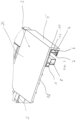
- Fig. 1
- einen Ausschnitt eines ersten erfindungsgemäßen Bettgestells;
- Fig. 2
- einen Ausschnitt eines zweiten erfindungsgemäßen Bettgestells;
- Fig. 3
- einen Ausschnitt eines dritten erfindungsgemäßen Bettgestells;
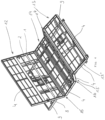
- Fig. 4
- ein Bettgestell ohne Abdeckvorrichtung in Ansicht.
- Die Figuren zeigen verschiedene Ausführungsformen eines erfindungsgemäßen Bettgestells. Die Bettgestelle weisen sämtlich ein umlaufendes erstes Rahmenteil 1, ein am ersten Rahmenteil 1 befestigtes formstabiles Auflageteil 2 und eine das erste Rahmenteil 1 samt Auflageteil 2 überdeckende Abdeckvorrichtung 3 auf. Zudem ist eine mehrteilige umlaufende Spannleiste 4 vorgesehen, die von Rändern 5 der Abdeckvorrichtung 3 überdeckt und umgriffen ist. Die Ränder 5 sind mit ihren freien, die Spannleiste 4 überragenden Endbereichen umgeschlagen und unterseitig an Bestandteilen der Spannleiste 4 fixiert sind.
- Das umlaufende erste Rahmenteil 1 besteht aus einem Hohlprofilrahmen aus Metall mit einem quadratischen Querschnitt, wobei an diesem ein Auflageteil 2 in Form eines Metallgitters befestigt ist. Die quadratische Querschnittsform des ersten Rahmenteils 1 ermöglicht es, das Auflageteil 2 auf einen Schenkel des ersten Rahmenteils 1 auflegen zu können und mit diesem zu verschweißen. Eine Spannleiste 4 ist an einem umlaufenden Streifen 10 aus Metall befestigt, der ebenfalls auf den Schenkel des ersten Rahmenteils 1 aufgelegt und mit diesem verschweißt ist. Der Streifen 10 und das Metallgitter bilden eine gemeinsame Auflageebene.
- Eine Abdeckvorrichtung 3, die z.B. ein Stofftuch sein kann, ist in den
Fig. 1 bis 3 über das Rahmenteil 1 samt Auflageteil 2 und Spannleiste 4 gespannt und ist mit Klemmstücken 7, die an Endbereichen des Stofftuches (Abdeckvorrichtung 2) befestigt sind, auf die Spannleiste 4 aufgesteckt. - Die Spannleiste 4 ist ein Hohlprofil aus Metall mit einem im Wesentlichen rechteckigen Querschnitt. Das Hohlprofil (Spannleiste 4) ist in dessen Längserstreckung dem ersten Rahmenteil 1 folgend ausgerichtet und umlaufend am ersten Rahmenteil 1 befestigt. Es erstreckt sich quer zu der Auflageebene des Auflageteils 2 und weist einen parallel zum Auflageteil 2 abragenden ersten Profilschenkel 6 auf, der einen Abstand von der Auflageebene hat und sich unterhalb des Auflageteils 2 erstreckt. Auf den ersten Profilschenkel 6 sind die Klemmstücke 7 aufgesteckt, die an den Endbereichen der Abdeckvorrichtung 3 befestigt sind, um die Abdeckvorrichtung 3 auf dem Gestell festzuspannen und daran zu halten. Durch Aufstecken der Klemmstücke 7 auf den ersten Profilschenkel 6, kann die Abdeckvorrichtung 3 schnell und einfach an der Spannleiste 4 befestigt werden. Die Klemmstücke 7 können genauso einfach wieder von dem ersten Profilschenkel 6 abgezogen werden, um die Abdeckvorrichtung 3 von dem Gestell abzunehmen und beispielsweise zu waschen oder auszutauschen.
- Die Klemmstücke 7 sind leistenartige Klemmhalter mit einem etwa U-förmigen Querschnitt aus Kunststoff und können im Stranggussverfahren kostengünstig hergestellt werden. Die U-Form ermöglicht es, das Klemmstück 7 auf den Profilschenkel 6 aufzustecken, wobei die leistenartige Form des Klemmhalters 7 einen verbesserten Einzug gewährleistet, d.h. die Faltenbildung am Rand 5 der Abdeckvorrichtung 3 verhindert. Die Klemmstücke 7 sind an den Endbereichen der Abdeckvorrichtung 3 angenäht, sodass eine dauerhafte und stabile Befestigung sichergestellt ist.
-
Fig. 4 zeigt ein zweites Rahmenteil 8 mit Haltern 9 und daran befestigten Bettfüßen vorgesehen, wobei das Rahmenteil 1 an dem zweiten Rahmenteil 8 befestigt ist. Das zweite Rahmenteil 8 bietet für das Bettgestell eine verbesserte Stabilität. Sofern das erste Rahmenteil 1 bewegbare Teile aufweist, wie es inFig. 4 gezeigt ist, können diese durch Scharniere oder Gelenkhebel an dem zweiten Rahmenteil 8 befestigt sein und relativ zu dem zweiten Rahmenteil 8 verstellt werden. - Das erste Rahmenteil 1, das zweite Rahmenteil 8 sowie das Auflageteil 2 bestehen aus Metall. Dadurch lassen sich sämtliche Bauteile durch Schweißen kostengünstig und dauerhaft miteinander verbinden.
- Der Streifen 10 dient als Erweiterung des Auflageteils 2. Auf dem Streifen 10 können beispielsweise Polsterteile aufgelegt werden, wie es in
Fig. 3 gezeigt ist. Wesentlich ist dabei, dass das Auflageteil 2 und der Steifen 10 in der Weise an dem ersten Rahmenteil 1 befestigt sind, dass diese eine ebene Auflagefläche bilden. - In
Fig. 4 ist ein Bettgestell ohne Abdeckvorrichtung gezeigt, welches verstellbare Segmente aufweist. Dazu ist das erste Rahmenteil 1 samt Auflageteil 2 und die Spannleiste 4 in ein verstellbares Kopfteil 12, ein verstellbares Fußteil 13 und ein feststehendes Mittelteil 14 unterteilt. Das erste Rahmenteil 1 ist mit seinem Mittelteil 14 an dem zweiten Rahmenteil 8 fest verschweißt, wobei das Kopfteil 12 und das Fußteil 13 relativ zu dem zweiten Rahmenteil 8 verstellbar sind. - Die Ränder 5 der Abdeckvorrichtung weisen in ersten Übergangsbereichen 15 zwischen dem Mittelteil 14 und dem Kopfteil 12 und in zweiten Übergangsbereichen 16 zwischen dem Mittelteil 14 und dem Fußteil 13 jeweils einen Schlitz auf, durch den die Ränder in Randabschnitte geteilt sind. An jedem Randabschnitt ist ein Klemmstück befestigt. Das Fußteil ist in weitere zwei Teile 13',13" unterteilt. Diese Ausgestaltung ermöglicht eine Verstellung der gesamten mit der Abdeckvorrichtung 3 bespannten Teile des Bettgestells. Das Bettgestell behält also auch bei einer Verstellung von Kopf- 12 und/oder Fußteil 13 seine ansprechende Erscheinung, weil die Abdeckung 3 an den bewegten Teilen gehalten ist und mitbewegt wird. Da die Klemmstücke 7 nicht ausreichend elastisch sind, müssen diese in den Übergangsbereichen 15,16,17 durchtrennt sein, um die entsprechende Bewegung zuzulassen. Die Verstellung des Kopfteils 12 und des Fußteils 13 oder der Fußteile 13',13" erfolgt elektrisch, um den Komfort zu erhöhen. Elektrische Antriebe sind in
Fig. 4 unterhalb des Kopfteles 12 und unterhalb des Fußteiles 13 ersichtlich. - In einer einfachen Ausführungsform ist die Abdeckvorrichtung 3 unmittelbar auf das Auflageteil 2 aufgelegt, wie es
Fig. 1 zeigt.Fig. 2 zeigt ein Ausführungsbeispiel, bei dem die Abdeckvorrichtung 3 zusätzlich mit einem Schaumstoff 18 versteppt ist, der zwischen der Abdeckvorrichtung 3 und dem Auflageteil 2 angeordnet ist, wobei der Schaumstoff 18 beispielsweise als Schutz der Abdeckvorrichtung 3 dienen kann. InFig. 3 ist eine Ausführungsform gezeigt, bei der auf das Auflageteil 2 und/oder den Streifen 10 eine Taschenfederkernmatratze 19 aufgelegt ist, wobei das Auflageteil 2 samt Polsterung von der Abdeckvorrichtung 3 überdeckt ist. Auf das Auflageteil 2 kann eine weitere Federkernmatratze aufgelegt sein, auf die ein Topper aufgebracht wird. Dieser Aufbau ist an sich für ein Boxspringbett bekannt. - Die Abdeckvorrichtung 3 ist vorzugsweise ein quaderartiger Bezug, mit einer Oberseite 20, die zumindest über das Auflagerteil 2 und einen Teil des ersten Rahmenteils 1 gespannt ist, mit Rändern 5 als Seitenwände des quaderartigen Bezuges, die einen Teil des ersten Rahmenteils 1 und die Spannleiste 4 überdecken und an deren Endbereichen die Klemmstücke 7 befestigt sind, die auf die Profilschenkel 6 aufgesteckt sind und mit denen der Bezug in Solllage gehalten ist und mit einer Unterseite, die eine quadratische oder rechteckige durch die Endbereiche und die daran befestigten Klemmstücke 7 eingerahmte Öffnung aufweist. Die Öffnung ist vorgesehen, um den Bezug über die zu überdeckenden Teile des Bettgestells ziehen und ausrichten zu können. Mit den Klemmstücken 7 wird der Bezug dann an den Profilschenkel 6 unter Spannung fixiert.
- Die Erfindung ist nicht auf die Ausführungsbeispiele beschränkt, sondern im Rahmen der Offenbarung vielfach variabel.
- Alle in der Beschreibung und/oder Zeichnung offenbarten Einzel- und Kombinationsmerkmale werden als erfindungswesentlich angesehen.
-
- 1 erstes Rahmenteil
- 2 Auflageteil
- 3 Abdeckvorrichtung
- 4 Spannleiste
- 5 Ränder von 3
- 6 erster Profilschenkel
- 7 Klemmstücke
- 8 zweites Rahmenteil
- 9 Halter
- 10 Streifen
- 11 zweiter Profilschenkel
- 12 Kopfteil
- 13 Fußteil
- 14 Mittelteil
- 15 erster Übergangsbereich
- 16 zweiter Übergangsbereich
- 17 dritter Übergangsbereich
- 18 Schaumstoff
- 19 Matratze
- 20 Oberseite
Claims (22)
- Bettgestell- mit einem umlaufenden ersten Rahmenteil (1),- einem am ersten Rahmenteil (1) befestigten oder befestigbaren formstabilen Auflageteil (2),- einer das erste Rahmenteil (1) samt Auflageteil (2) überdeckenden Abdeckvorrichtung (3) und- einer mehrteiligen umlaufenden Spannleiste (4),- die von Rändern (5) der Abdeckvorrichtung (3) überdeckt und umgriffen ist, wobei die Ränder (5) mit ihren freien, die Spannleiste (4) überragenden Endbereichen umgeschlagen und unterseitig an Bestandteilen der Spannleiste (4) fixiert sind, dadurch gekennzeichnet, dass- die Spannleiste (4) ein Profil ist, welches sich quer zu einer Auflageebene des Auflageteils (2) erstreckt und einen parallel zum Auflageteil (2) abragenden ersten Profilschenkel (6) aufweist, der einen Abstand von der Auflageebene hat und sich unterhalb des Auflageteils (2) erstreckt, und- dass an den Endbereichen der Abdeckvorrichtung (3) Klemmstücke (7) befestigt sind, die in der Solllage auf den ersten Profilschenkel (6) aufgesteckt sind.
- Bettgestell nach Anspruch 1, dadurch gekennzeichnet, dass das Auflageteil (2) und die Spannleiste (4) sowie die Abdeckvorrichtung (3) an dem ersten Rahmenteil (1) befestigt sind, wobei das Bettgestell ein zweites Rahmenteil (8) aufweist, an dem das erste Rahmenteil (1) befestigt oder befestigbar ist.
- Bettgestell nach einem der Ansprüche 1 oder 2,
dadurch gekennzeichnet, dass das zweite Rahmenteil (8) Halter und daran befestigbare oder befestigte Bettfüße aufweist. - Bettgestell nach einem der Ansprüche 1 bis 3, dadurch gekennzeichnet, dass das erste Rahmenteil (1), das zweite Rahmenteil (8) sowie das Auflageteil (2) aus Metall bestehen.
- Bettgestell nach einem der Ansprüche 1 bis 4, dadurch gekennzeichnet, dass die Spannleiste (4) ein Metallprofil ist.
- Bettgestell nach einem der Ansprüche 1 bis 5, dadurch gekennzeichnet, dass die Spannleiste (4) ein Kunststoffprofil ist.
- Bettgestell nach einem der Ansprüche 1 bis 6, dadurch gekennzeichnet, dass die Klemmstücke (7) leistenartige Klemmhalter mit einem etwa U-förmigen Querschnitt sind.
- Bettgestell nach einem der Ansprüche 1 bis 7, dadurch gekennzeichnet, dass die Klemmstücke (7) Kunststoffprofile sind.
- Bettgestell nach einem der Ansprüche 1 bis 8, dadurch gekennzeichnet, dass die Klemmstücke (7) an den Endbereichen der Abdeckvorrichtung (3) angenäht sind.
- Bettgestell nach einem der Ansprüche 1 bis 9,
dadurch gekennzeichnet, dass die Spannleiste (4) ein Hohlprofil mit einem quadratischen oder rechteckigen Querschnitt ist, wobei ein parallel zum Auflageteil (2) gerichteter erster Profilschenkel (6) in Richtung unter das Auflageteil (2) verlängert ist, wobei der erste Profilschenkel (6) einen Abstand von der Auflageebene aufweist. - Bettgestell nach einem der Ansprüche 1 bis 10,
dadurch gekennzeichnet, dass die Spannleiste (4) ein L-Profil, ein U-Profil oder ein C-Profil ist, wobei wenigstens ein erster Profilschenkel (6) parallel zum Auflageteil (2) in Richtung unter das Auflageteil (2) gerichtet ist und wenigstens ein zweiter Profilschenkel quer zur Auflageebene gerichtet ist. - Bettgestell nach einem der Ansprüche 1 bis 11,
dadurch gekennzeichnet, dass am Rahmenteil (1) ein vorzugsweise umlaufender Streifen (10) aus Metall oder Kunststoff zur Erweiterung des Auflageteils (2) befestigt ist, wobei der Streifen (10) und das Auflageteil (2) in einer Ebene angeordnet sind, sodass die der Aufstandsebene des Bettgestells abgewandte Oberfläche des Streifens (10) und des Auflageteils (2) eine gemeinsame ebene Auflagefläche bilden. - Bettgestell nach einem der Ansprüche 1 bis 12,
dadurch gekennzeichnet, dass die Spannleiste (4) einen zweiten Profilschenkel (11) aufweist, mit dem die Spannleiste (4) an dem ersten Rahmenteil (1) befestigt ist, wobei der zweite Schenkel (11) der Streifen (10) ist, mit dem die Spannleiste (4) am ersten Rahmenteil (1) befestigt ist. - Bettgestell nach einem der Ansprüche 1 bis 13,
dadurch gekennzeichnet, dass das erste Rahmenteil (1) samt Auflageteil (2) und die Spannleiste (4) in ein verstellbares Kopfteil (12), ein verstellbares Fußteil (13) und ein feststehendes Mittelteil (14) unterteilt ist, wobei das erste Rahmenteil (1) mit seinem Mittelteil (14) an dem zweiten Rahmenteil (8) fest fixiert ist, vorzugsweise verschweißt oder verschraubt ist, und das Kopfteil (12) und das Fußteil (13) relativ zu dem zweiten Rahmenteil (8) verstellbar sind, wobei die Ränder (5) der Abdeckvorrichtung in ersten Übergangsbereichen (15) zwischen dem Mittelteil (14) und dem Kopfteil (12) und in zweiten Übergangsbereichen (16) zwischen dem Mittelteil (14) und dem Fußteil (13) jeweils einen Schlitz aufweisen, durch den die Ränder in Randabschnitte geteilt sind, wobei an jedem Randabschnitt ein Klemmstück (7) befestigt ist. - Bettgestell nach Anspruch 14, dadurch gekennzeichnet, dass das Fußteil (13) zwei relativ zueinander bewegbare Teile (13',13") aufweist, wobei der Randabschnitt des Fußteils (13) in einem dritten Übergangsbereich (17) zwischen den Teilen (13',13") einen Schlitz aufweist, durch den der Randbereich in weitere Abschnitte geteilt ist, wobei an jedem Abschnitt ein Klemmstück (7) befestigt ist.
- Bettgestell nach einem der Ansprüche 1 bis 15,
dadurch gekennzeichnet, dass das Kopfteil (12) und das Fußteil (13) oder die Fußteile (13',13") elektrisch verstellbar sind. - Bettgestell nach einem der Ansprüche 1 bis 16,
dadurch gekennzeichnet, dass die Abdeckvorrichtung (3) eine Tuchbespannung aus Textil oder Leder oder einer Kombination dieser Materialien ist. - Bettgestell nach einem der Ansprüche 1 bis 17,
dadurch gekennzeichnet, dass die Abdeckvorrichtung (3) mit einem Schaumstoff (18) versteppt ist. - Bettgestell nach einem der Ansprüche 1 bis 18,
dadurch gekennzeichnet, dass die Abdeckvorrichtung (3) aus einer Folie besteht. - Bettgestell nach einem der Ansprüche 1 bis 19,
dadurch gekennzeichnet, dass auf das Auflageteil (2) und/oder den Streifen (10) eine Polsterung aufgelegt ist, wobei die Polsterung vorzugsweise eine Matratze (19) mit einem Federkernaufbau oder Taschenfederkernaufbau ist, und wobei das Auflageteil (2) samt Matratze (19) von der Abdeckvorrichtung (3) überdeckt ist. - Bettgestell nach einem der Ansprüche 1 bis 20,
dadurch gekennzeichnet, dass die Abdeckvorrichtung (3) ein quaderartiger Bezug ist, mit einer Oberseite (20), die zumindest über das Auflageteil (2) und einen Teil des ersten Rahmenteils (1) gespannt ist, mit Rändern (5) als Seitenwände des quaderartigen Bezuges, die einen Teil des ersten Rahmenteils (1) und die Spannleiste (4) überdecken und an deren Endbereichen die Klemmstücke (7) befestigt sind, die auf die Profilschenkel (6) aufgesteckt sind und mit denen der Bezug in Solllage gehalten ist und mit einer Unterseite, die eine quadratische oder rechteckige durch die Endbereiche und die daran befestigten Klemmstücke (7) eingerahmte Öffnung aufweist. - Bettgestell nach einem der Ansprüche 1 bis 21,
dadurch gekennzeichnet, dass auf das Auflageteil (2) mindestens eine weitere Polsterung, vorzugsweise eine Matratze mit Federkernaufbau, aufgelegt oder auflegbar ist.
Applications Claiming Priority (1)
| Application Number | Priority Date | Filing Date | Title |
|---|---|---|---|
| DE102023124554.6A DE102023124554A1 (de) | 2023-09-12 | 2023-09-12 | Bettgestell |
Publications (2)
| Publication Number | Publication Date |
|---|---|
| EP4523571A1 true EP4523571A1 (de) | 2025-03-19 |
| EP4523571B1 EP4523571B1 (de) | 2025-10-22 |
Family
ID=91953861
Family Applications (1)
| Application Number | Title | Priority Date | Filing Date |
|---|---|---|---|
| EP24188743.9A Active EP4523571B1 (de) | 2023-09-12 | 2024-07-16 | Bettgestell |
Country Status (10)
| Country | Link |
|---|---|
| US (1) | US12557913B2 (de) |
| EP (1) | EP4523571B1 (de) |
| JP (1) | JP2025040940A (de) |
| KR (1) | KR20250038617A (de) |
| CN (1) | CN119606155A (de) |
| AU (1) | AU2024205086A1 (de) |
| CA (1) | CA3251894A1 (de) |
| DE (1) | DE102023124554A1 (de) |
| DK (1) | DK4523571T3 (de) |
| MX (1) | MX2024011151A (de) |
Cited By (1)
| Publication number | Priority date | Publication date | Assignee | Title |
|---|---|---|---|---|
| EP4714304A1 (de) * | 2024-09-19 | 2026-03-25 | Sino International Group Ltd. | Bettgestell mit einem gestellbezug |
Citations (3)
| Publication number | Priority date | Publication date | Assignee | Title |
|---|---|---|---|---|
| EP0699406A1 (de) * | 1994-09-02 | 1996-03-06 | Norma Boxmeer B.V. | Eine Kombination von Matratze und Bettrahmen |
| EP3659469A1 (de) * | 2018-11-28 | 2020-06-03 | Dieter Schwarz | Boxspringbett |
| DE102021122888A1 (de) * | 2021-09-03 | 2023-03-09 | Fey & Co. GmbH | Matratze für ein Boxspringbett sowie ein Boxspringbett |
Family Cites Families (4)
| Publication number | Priority date | Publication date | Assignee | Title |
|---|---|---|---|---|
| US3967331A (en) * | 1975-04-17 | 1976-07-06 | De Lamar Bed Spring Corporation | Springless bed spring |
| IT1258918B (it) * | 1992-05-15 | 1996-03-01 | Letto da riposo accessoriabile | |
| US7832040B2 (en) * | 2007-01-24 | 2010-11-16 | Sealy Technology Llc | Suspended flexible matrix support system |
| US8769740B2 (en) * | 2011-09-19 | 2014-07-08 | Zinus, Inc. | Collapsible, folding mattress support with adjustable elevating shoulder section |
-
2023
- 2023-09-12 DE DE102023124554.6A patent/DE102023124554A1/de active Pending
-
2024
- 2024-07-16 EP EP24188743.9A patent/EP4523571B1/de active Active
- 2024-07-16 DK DK24188743.9T patent/DK4523571T3/da active
- 2024-07-25 AU AU2024205086A patent/AU2024205086A1/en active Pending
- 2024-07-30 JP JP2024123148A patent/JP2025040940A/ja active Pending
- 2024-07-30 US US18/788,423 patent/US12557913B2/en active Active
- 2024-08-13 CA CA3251894A patent/CA3251894A1/en active Pending
- 2024-09-10 KR KR1020240123246A patent/KR20250038617A/ko active Pending
- 2024-09-11 CN CN202411269626.2A patent/CN119606155A/zh active Pending
- 2024-09-11 MX MX2024011151A patent/MX2024011151A/es unknown
Patent Citations (3)
| Publication number | Priority date | Publication date | Assignee | Title |
|---|---|---|---|---|
| EP0699406A1 (de) * | 1994-09-02 | 1996-03-06 | Norma Boxmeer B.V. | Eine Kombination von Matratze und Bettrahmen |
| EP3659469A1 (de) * | 2018-11-28 | 2020-06-03 | Dieter Schwarz | Boxspringbett |
| DE102021122888A1 (de) * | 2021-09-03 | 2023-03-09 | Fey & Co. GmbH | Matratze für ein Boxspringbett sowie ein Boxspringbett |
Cited By (1)
| Publication number | Priority date | Publication date | Assignee | Title |
|---|---|---|---|---|
| EP4714304A1 (de) * | 2024-09-19 | 2026-03-25 | Sino International Group Ltd. | Bettgestell mit einem gestellbezug |
Also Published As
| Publication number | Publication date |
|---|---|
| US12557913B2 (en) | 2026-02-24 |
| US20250082105A1 (en) | 2025-03-13 |
| DK4523571T3 (da) | 2025-11-10 |
| DE102023124554A1 (de) | 2025-03-13 |
| AU2024205086A1 (en) | 2025-03-27 |
| KR20250038617A (ko) | 2025-03-19 |
| CN119606155A (zh) | 2025-03-14 |
| EP4523571B1 (de) | 2025-10-22 |
| MX2024011151A (es) | 2025-04-02 |
| JP2025040940A (ja) | 2025-03-25 |
| CA3251894A1 (en) | 2025-06-04 |
Similar Documents
| Publication | Publication Date | Title |
|---|---|---|
| DE69200793T2 (de) | Fahrzeugsitzrückenlehnen. | |
| DE1945583C3 (de) | Sitz- oder Liegemöbel mit einem Stützteil zur Abstützung des menschlichen Körpers | |
| EP1438213B1 (de) | Netzanordnung zur montage an einem rahmen | |
| DE3410353A1 (de) | Sitzstuetze fuer einen fahrzeugsitz | |
| EP4523571B1 (de) | Bettgestell | |
| DE19901203A1 (de) | Rückenlehne eines Sitzes mit eingezogener Rückseite | |
| DE2248264B2 (de) | Sitzmöbel | |
| DE10009228A1 (de) | Fahrzeugsitz | |
| DE2239758C3 (de) | Vorrichtung zum Bespannen von Wandflächen mit elastischen Bespannstoffen | |
| EP0039053A2 (de) | Vorrichtung zum Verbinden von Bezugstoff mit einem Trägerkörper, insbesondere einem Möbelkörper, und/oder zum Abdecken von insbesondere Randbereichen des Trägerkörpers | |
| DE102006024308B4 (de) | Vorrichtung zur Befestigung eines Bezugs an einem Polsterkörper eines Sitzes und Verfahren zur Herstellung der Befestigungsvorrichtung | |
| CH535559A (de) | Sitzmöbel | |
| EP0595310A1 (de) | Polstermöbel | |
| DE3219637A1 (de) | Liege fuer pkw's | |
| DE2507320C3 (de) | Sitz- und Liegemöbel mit drei Polsterkissen gleicher Breite | |
| DE2746133C3 (de) | Sitzfederung | |
| DE2606115A1 (de) | Sitz | |
| DE102024126956A1 (de) | Bausatz zum Zusammenbau eines Bettrahmens | |
| DE102024126944A1 (de) | Bettgestell mit einem Gestellbezug | |
| DE2513955C3 (de) | Bettuchhalter | |
| DE2853010A1 (de) | Spannvorrichtung fuer stoffe, bezuege o.dgl. | |
| DE20314844U1 (de) | Kinderfahrradanhänger | |
| DE1903544C3 (de) | Sitzrahmen mit Polsterbezug für Fahrzeugsitze, Sitzmöbel oder Liegemöbel | |
| DE366478C (de) | Kopfstuetze fuer Betten u. dgl. | |
| DE1654374C (de) | Matratze |
Legal Events
| Date | Code | Title | Description |
|---|---|---|---|
| PUAI | Public reference made under article 153(3) epc to a published international application that has entered the european phase |
Free format text: ORIGINAL CODE: 0009012 |
|
| STAA | Information on the status of an ep patent application or granted ep patent |
Free format text: STATUS: THE APPLICATION HAS BEEN PUBLISHED |
|
| AK | Designated contracting states |
Kind code of ref document: A1 Designated state(s): AL AT BE BG CH CY CZ DE DK EE ES FI FR GB GR HR HU IE IS IT LI LT LU LV MC ME MK MT NL NO PL PT RO RS SE SI SK SM TR |
|
| STAA | Information on the status of an ep patent application or granted ep patent |
Free format text: STATUS: REQUEST FOR EXAMINATION WAS MADE |
|
| 17P | Request for examination filed |
Effective date: 20250328 |
|
| RAX | Requested extension states of the european patent have changed |
Extension state: BA Payment date: 20250328 |
|
| GRAP | Despatch of communication of intention to grant a patent |
Free format text: ORIGINAL CODE: EPIDOSNIGR1 |
|
| STAA | Information on the status of an ep patent application or granted ep patent |
Free format text: STATUS: GRANT OF PATENT IS INTENDED |
|
| INTG | Intention to grant announced |
Effective date: 20250522 |
|
| GRAS | Grant fee paid |
Free format text: ORIGINAL CODE: EPIDOSNIGR3 |
|
| GRAA | (expected) grant |
Free format text: ORIGINAL CODE: 0009210 |
|
| STAA | Information on the status of an ep patent application or granted ep patent |
Free format text: STATUS: THE PATENT HAS BEEN GRANTED |
|
| P01 | Opt-out of the competence of the unified patent court (upc) registered |
Free format text: CASE NUMBER: UPC_APP_3517_4523571/2025 Effective date: 20250818 |
|
| AK | Designated contracting states |
Kind code of ref document: B1 Designated state(s): AL AT BE BG CH CY CZ DE DK EE ES FI FR GB GR HR HU IE IS IT LI LT LU LV MC ME MK MT NL NO PL PT RO RS SE SI SK SM TR |
|
| REG | Reference to a national code |
Ref country code: CH Ref legal event code: F10 Free format text: ST27 STATUS EVENT CODE: U-0-0-F10-F00 (AS PROVIDED BY THE NATIONAL OFFICE) Effective date: 20251022 Ref country code: GB Ref legal event code: FG4D Free format text: NOT ENGLISH |
|
| REG | Reference to a national code |
Ref country code: CH Ref legal event code: R17 Free format text: ST27 STATUS EVENT CODE: U-0-0-R10-R17 (AS PROVIDED BY THE NATIONAL OFFICE) Effective date: 20251105 |
|
| REG | Reference to a national code |
Ref country code: DE Ref legal event code: R096 Ref document number: 502024000323 Country of ref document: DE |
|
| REG | Reference to a national code |
Ref country code: DK Ref legal event code: T3 Effective date: 20251106 |
|
| REG | Reference to a national code |
Ref country code: NL Ref legal event code: FP |
|
| REG | Reference to a national code |
Ref country code: IE Ref legal event code: FG4D Free format text: LANGUAGE OF EP DOCUMENT: GERMAN |
|
| REG | Reference to a national code |
Ref country code: DE Ref legal event code: R082 Ref document number: 502024000323 Country of ref document: DE Representative=s name: KOECHLING, MARIETTA, M.SC B.ENG., DE |
|
| PG25 | Lapsed in a contracting state [announced via postgrant information from national office to epo] |
Ref country code: ES Free format text: LAPSE BECAUSE OF FAILURE TO SUBMIT A TRANSLATION OF THE DESCRIPTION OR TO PAY THE FEE WITHIN THE PRESCRIBED TIME-LIMIT Effective date: 20251022 |
|
| REG | Reference to a national code |
Ref country code: LT Ref legal event code: MG9D |
|
| PG25 | Lapsed in a contracting state [announced via postgrant information from national office to epo] |
Ref country code: NO Free format text: LAPSE BECAUSE OF FAILURE TO SUBMIT A TRANSLATION OF THE DESCRIPTION OR TO PAY THE FEE WITHIN THE PRESCRIBED TIME-LIMIT Effective date: 20260122 |
|
| PG25 | Lapsed in a contracting state [announced via postgrant information from national office to epo] |
Ref country code: FI Free format text: LAPSE BECAUSE OF FAILURE TO SUBMIT A TRANSLATION OF THE DESCRIPTION OR TO PAY THE FEE WITHIN THE PRESCRIBED TIME-LIMIT Effective date: 20251022 Ref country code: HR Free format text: LAPSE BECAUSE OF FAILURE TO SUBMIT A TRANSLATION OF THE DESCRIPTION OR TO PAY THE FEE WITHIN THE PRESCRIBED TIME-LIMIT Effective date: 20251022 |
|
| PG25 | Lapsed in a contracting state [announced via postgrant information from national office to epo] |
Ref country code: RS Free format text: LAPSE BECAUSE OF FAILURE TO SUBMIT A TRANSLATION OF THE DESCRIPTION OR TO PAY THE FEE WITHIN THE PRESCRIBED TIME-LIMIT Effective date: 20260122 |
|
| PG25 | Lapsed in a contracting state [announced via postgrant information from national office to epo] |
Ref country code: IS Free format text: LAPSE BECAUSE OF FAILURE TO SUBMIT A TRANSLATION OF THE DESCRIPTION OR TO PAY THE FEE WITHIN THE PRESCRIBED TIME-LIMIT Effective date: 20260222 |
|
| PG25 | Lapsed in a contracting state [announced via postgrant information from national office to epo] |
Ref country code: PT Free format text: LAPSE BECAUSE OF FAILURE TO SUBMIT A TRANSLATION OF THE DESCRIPTION OR TO PAY THE FEE WITHIN THE PRESCRIBED TIME-LIMIT Effective date: 20260223 |
|
| PG25 | Lapsed in a contracting state [announced via postgrant information from national office to epo] |
Ref country code: PL Free format text: LAPSE BECAUSE OF FAILURE TO SUBMIT A TRANSLATION OF THE DESCRIPTION OR TO PAY THE FEE WITHIN THE PRESCRIBED TIME-LIMIT Effective date: 20251022 |
|
| PG25 | Lapsed in a contracting state [announced via postgrant information from national office to epo] |
Ref country code: LV Free format text: LAPSE BECAUSE OF FAILURE TO SUBMIT A TRANSLATION OF THE DESCRIPTION OR TO PAY THE FEE WITHIN THE PRESCRIBED TIME-LIMIT Effective date: 20251022 |
|
| PG25 | Lapsed in a contracting state [announced via postgrant information from national office to epo] |
Ref country code: BG Free format text: LAPSE BECAUSE OF FAILURE TO SUBMIT A TRANSLATION OF THE DESCRIPTION OR TO PAY THE FEE WITHIN THE PRESCRIBED TIME-LIMIT Effective date: 20251022 |
|
| PG25 | Lapsed in a contracting state [announced via postgrant information from national office to epo] |
Ref country code: LT Free format text: LAPSE BECAUSE OF FAILURE TO SUBMIT A TRANSLATION OF THE DESCRIPTION OR TO PAY THE FEE WITHIN THE PRESCRIBED TIME-LIMIT Effective date: 20251022 |
|
| PG25 | Lapsed in a contracting state [announced via postgrant information from national office to epo] |
Ref country code: SM Free format text: LAPSE BECAUSE OF FAILURE TO SUBMIT A TRANSLATION OF THE DESCRIPTION OR TO PAY THE FEE WITHIN THE PRESCRIBED TIME-LIMIT Effective date: 20251022 |
|
| PG25 | Lapsed in a contracting state [announced via postgrant information from national office to epo] |
Ref country code: EE Free format text: LAPSE BECAUSE OF FAILURE TO SUBMIT A TRANSLATION OF THE DESCRIPTION OR TO PAY THE FEE WITHIN THE PRESCRIBED TIME-LIMIT Effective date: 20251022 |
|
| PG25 | Lapsed in a contracting state [announced via postgrant information from national office to epo] |
Ref country code: CZ Free format text: LAPSE BECAUSE OF FAILURE TO SUBMIT A TRANSLATION OF THE DESCRIPTION OR TO PAY THE FEE WITHIN THE PRESCRIBED TIME-LIMIT Effective date: 20251022 |
|
| PG25 | Lapsed in a contracting state [announced via postgrant information from national office to epo] |
Ref country code: SK Free format text: LAPSE BECAUSE OF FAILURE TO SUBMIT A TRANSLATION OF THE DESCRIPTION OR TO PAY THE FEE WITHIN THE PRESCRIBED TIME-LIMIT Effective date: 20251022 |
|
| PG25 | Lapsed in a contracting state [announced via postgrant information from national office to epo] |
Ref country code: SE Free format text: LAPSE BECAUSE OF FAILURE TO SUBMIT A TRANSLATION OF THE DESCRIPTION OR TO PAY THE FEE WITHIN THE PRESCRIBED TIME-LIMIT Effective date: 20251022 |