EP4516691A2 - Ausgussbeutel - Google Patents
Ausgussbeutel Download PDFInfo
- Publication number
- EP4516691A2 EP4516691A2 EP25150809.9A EP25150809A EP4516691A2 EP 4516691 A2 EP4516691 A2 EP 4516691A2 EP 25150809 A EP25150809 A EP 25150809A EP 4516691 A2 EP4516691 A2 EP 4516691A2
- Authority
- EP
- European Patent Office
- Prior art keywords
- spout
- flange
- film
- pouch
- region
- Prior art date
- Legal status (The legal status is an assumption and is not a legal conclusion. Google has not performed a legal analysis and makes no representation as to the accuracy of the status listed.)
- Pending
Links
Images










Classifications
-
- B—PERFORMING OPERATIONS; TRANSPORTING
- B65—CONVEYING; PACKING; STORING; HANDLING THIN OR FILAMENTARY MATERIAL
- B65D—CONTAINERS FOR STORAGE OR TRANSPORT OF ARTICLES OR MATERIALS, e.g. BAGS, BARRELS, BOTTLES, BOXES, CANS, CARTONS, CRATES, DRUMS, JARS, TANKS, HOPPERS, FORWARDING CONTAINERS; ACCESSORIES, CLOSURES, OR FITTINGS THEREFOR; PACKAGING ELEMENTS; PACKAGES
- B65D75/00—Packages comprising articles or materials partially or wholly enclosed in strips, sheets, blanks, tubes or webs of flexible sheet material, e.g. in folded wrappers
- B65D75/52—Details
- B65D75/54—Cards, coupons or other inserts or accessories
- B65D75/56—Handles or other suspension means
- B65D75/566—Hand holes or suspension apertures
-
- B—PERFORMING OPERATIONS; TRANSPORTING
- B65—CONVEYING; PACKING; STORING; HANDLING THIN OR FILAMENTARY MATERIAL
- B65D—CONTAINERS FOR STORAGE OR TRANSPORT OF ARTICLES OR MATERIALS, e.g. BAGS, BARRELS, BOTTLES, BOXES, CANS, CARTONS, CRATES, DRUMS, JARS, TANKS, HOPPERS, FORWARDING CONTAINERS; ACCESSORIES, CLOSURES, OR FITTINGS THEREFOR; PACKAGING ELEMENTS; PACKAGES
- B65D75/00—Packages comprising articles or materials partially or wholly enclosed in strips, sheets, blanks, tubes or webs of flexible sheet material, e.g. in folded wrappers
- B65D75/52—Details
- B65D75/58—Opening or contents-removing devices added or incorporated during package manufacture
- B65D75/5861—Spouts
- B65D75/5872—Non-integral spouts
- B65D75/5877—Non-integral spouts connected to a planar surface of the package wall
-
- B—PERFORMING OPERATIONS; TRANSPORTING
- B65—CONVEYING; PACKING; STORING; HANDLING THIN OR FILAMENTARY MATERIAL
- B65D—CONTAINERS FOR STORAGE OR TRANSPORT OF ARTICLES OR MATERIALS, e.g. BAGS, BARRELS, BOTTLES, BOXES, CANS, CARTONS, CRATES, DRUMS, JARS, TANKS, HOPPERS, FORWARDING CONTAINERS; ACCESSORIES, CLOSURES, OR FITTINGS THEREFOR; PACKAGING ELEMENTS; PACKAGES
- B65D2547/00—Closures with filling and discharging, or with discharging, devices
- B65D2547/04—Closures with discharging devices other than pumps
- B65D2547/06—Closures with discharging devices other than pumps with pouring spouts ot tubes; with discharge nozzles or passages
- B65D2547/063—Details of spouts
- B65D2547/066—Details of spouts inserted in or attached to the base element
Definitions
- the breakage of the pouch main body is presumably caused by the spout rotating (tilting) with respect to the spout attachment film when the spout pouch is dropped, a moment load being applied to the vicinity of the flange outer peripheral edge, and the vicinity of the flange outer peripheral edge, with the moment load applied, striking the floor or the like.
- the spout pouch in the known related art of Patent Document 2 in a usage mode in which the pouch is lifted to dispense the liquid contents or the like, the spout may unexpectedly move due to the weight of the liquid contents contained in the spout or the like at the time of dispensing the liquid contents, resulting in the problem that an orientation of a dispensing cylindrical portion of the spout is difficult to set, making it difficult to dispense the liquid contents.
- the present invention has been made to solve these problems, and an object of the present invention is to provide a spout pouch that, with a simple configuration, improves an ease of dispensing liquid contents through a spout, and suppresses breakage of a pouch main body starting from the vicinity of a flange outer peripheral edge.
- a spout pouch includes a pouch main body and a spout attached to the pouch main body.
- the pouch main body includes a spout attachment film to which the spout is attached, and a side film connected to the spout attachment film by a connection seal formed on both sides of the spout attachment film in a transverse direction.
- the spout attachment film includes a flange facing region where a flange of the spout faces the spout attachment film.
- the pouch main body includes a shape control sealing portion formed by fusing a portion of the spout attachment film positioned inward of the connection seal in the transverse direction and the side film.
- the shape control sealing portion includes a portion positioned in a region between the flange facing region and the connection seal in the transverse direction.
- a spout pouch includes a front side film, a rear side film, a side gusset film disposed between the front side film and the rear side film at a pouch side portion and thermally fused to the front side film and the rear side film by a side seal, and a spout attached to the side gusset film.
- the side gusset film includes a front side sealing region thermally fused to the front side film at the side seal, a rear side sealing region thermally fused to the rear side film at the side seal, and a non-sealing region that is a region inward of the front side sealing region and the rear side sealing region.
- the non-sealing region includes a front side outer edge that is a boundary with the front side sealing region, and a rear side outer edge that is a boundary with the rear side sealing region.
- the front side outer edge and the rear side outer edge each include a base edge portion, the base edge portion of the front side outer edge and the base edge portion of the rear side outer edge being disposed spaced apart from each other in a front-rear direction, and an upper side inclined edge portion extending from an upper end of the base edge portion to an upper end coupling portion coupling an upper end of the front side outer edge and an upper end of the rear side outer edge.
- At least a portion of a flange of the spout is disposed facing a region between the upper side inclined edge portion of the front side outer edge and the upper side inclined edge portion of the rear side outer edge.
- a spout pouch includes a pouch main body and a spout attached to the pouch main body.
- the pouch main body includes a spout attachment film to which the spout is attached.
- the spout includes a flange disposed facing the spout attachment film.
- the flange includes a flange fixing portion fixed to the spout attachment film, and a flange buffering portion formed in at least a partial region of an outer periphery of the flange fixing portion and not fixed to the spout attachment film.
- the pouch main body includes the shape control sealing portion formed by fusing a portion of the spout attachment film positioned inward of the connection seal in the transverse direction and the side film, and the shape control sealing portion includes the portion positioned in a region between the flange facing region and the connection seal in the transverse direction, thereby making, by formation of the shape control sealing portion, a transverse direction interval between sealing portions on both sides in the transverse direction narrower than a peripheral area.
- the spout is attached at a position, among a first side and a second side in a longitudinal direction, closer to the second side than to a center of the spout attachment film in the longitudinal direction
- the pouch main body includes, as the shape control sealing portion, a first shape control sealing portion including a portion positioned in a region between the first facing region and the connection seal in the transverse direction.
- the spout when the spout is attached closer to the second side than the center of the spout attachment film in the longitudinal direction, the spout is inclined toward the second side due to the spout attachment film bulging outward by the weight of the liquid contents.
- the posture (orientation) of the spout can be corrected.
- a second shape control sealing portion includes a portion positioned in a region between the second facing region and the connection seal.
- a transverse direction dimension from the connection seal to an innermost top portion of the first shape control sealing portion is set to be equal to or greater than a transverse direction dimension from the connection seal to an innermost top portion of the second shape control sealing portion.
- the pouch main body includes, as the shape control sealing portion, a second shape control sealing portion including a portion positioned in a region between the second facing region and the connection seal in the transverse direction.
- the shape control sealing portion is formed on both sides with the flange facing region interposed therebetween. This makes it possible to favorably exhibit the effect of preventing breakage of the pouch main body starting from the vicinity of the flange outer peripheral edge by the shape control sealing portions.
- At least a portion of a flange of the spout is disposed facing a region between the upper side inclined edge portions of the side gusset film.
- the flange of the spout in the region between the upper side inclined edge portions, which has a narrow transverse width in the front-rear direction as compared with the region between the base edge portions, it is possible to not only narrow the interval between the inner edge of the sealing region (side seal) of the side gusset film and the flange outer peripheral edge, but also, because the region between the upper side inclined edge portions is an area of the side gusset film that is positioned on the upper side in a state in which the spout pouch is placed on a placement surface, and is an area in which a design change of the edge portion shape does not affect the self-supporting property of the pouch main body and the like, to freely change the design of the edge portion shape and favorably restrain the movement of the spout.
- the region between the upper side inclined edge portions of the side gusset film is an area that inclines inward of the pouch body toward the upper side in a state in which the spout pouch is placed on a placement surface and thus, even when the spout pouch is dropped with the position of the flange of the spout recessed inward of the pouch main body, it is easy to make it difficult for the side gusset film in the vicinity of the flange outer peripheral edge to come into contact with the floor or the like, making it possible to suppress breakage of the pouch main body starting from the vicinity of the flange outer peripheral edge and inwardly retract the tip end position of the dispensing cylindrical portion of the spout into the pouch main body as compared with a case in which the spout is mounted in a region between the base edge portions of the side gusset film.
- the upper side inclined edge portion is constituted by at least two inclined portions having different inclination angles with respect to an up-down direction. This makes it possible to adjust the inclination angles of these portions to adjust the edge portion shape of the upper side inclined edge portion, and thus narrow the interval between the inner edge of the sealing region (side seal) of the side gusset film and the flange outer peripheral edge as well as the interval between the upper inclined edge portions (side seals), and favorably adjust the inclination angle of the flange with a simple structure.
- the upper side inclined edge portion includes a gently inclined portion connecting a portion positioned above and inward in the front-rear direction relative to the upper end of the base edge portion, and a steeply inclined portion connecting an upper end of the gently inclined portion and an upper end coupling portion, and at least a portion of the flange of the spout is disposed facing a region between the gently inclined portion of the front side outer edge and the gently inclined portion of the rear side outer edge.
- the spout is attached in a region between the gently inclined portions where the inclination angle inclined inwardly in the pouch main body toward the upper side is gentle, making it possible to reduce the inclination angle of the flange relative to the up-down direction of the pouch main body and adjust the extending direction of the dispensing cylindrical portion of the spout downward.
- At least one of the front side sealing region and the rear side sealing region includes a control sealing portion positioned inward of a first virtual line in the front-rear direction, and the control sealing portion includes an area positioned in a region between a lower half of the flange facing region and the front side sealing region or the rear side sealing region in the front-rear direction.
- the liquid contents are accommodated in a liquid contents accommodating portion of the spout pouch in an amount, in an unopened state, equal to or less than a volume of a portion of the liquid contents accommodating portion below a virtual line obtained by extending a lower end edge of an inner peripheral surface of a dispensing hole of the spout in an extending direction of the lower end edge, when viewed in the front-rear direction.
- the flange includes a flange buffering portion formed in at least a partial region of an outer periphery of the flange fixing portion and not fixed to the spout attachment film.
- the flange buffering portion by formation of the flange buffering portion, it is possible to suppress the breakage of the pouch main body starting from the vicinity of a portion of the flange outer peripheral edge facing the first side or a portion of the flange outer peripheral edge facing the second side in the longitudinal direction, which is a portion where breakage is likely to occur.
- the flange buffering portion includes a retracted portion including an outer peripheral side tip end portion positioned on a side away from the spout attachment film. This makes it possible to suppress application of an excessive force to the spout attachment film due to contact with the flange outer peripheral edge.
- the pouch main body includes a first shape control sealing portion formed by fusing a portion of the spout attachment film positioned inward of the connection seal in the transverse direction and the side film, and the first shape control sealing portion includes a portion positioned in a region between the flange facing region and the connection seal in the transverse direction, thereby making, by formation of the first shape control sealing portion, a transverse direction interval between sealing portions on both sides in the transverse direction narrower than a peripheral area.
- a spout pouch 110 according to an embodiment of the present invention will be described below with reference to the drawings.
- the spout pouch 110 accommodates liquid contents, such as drinking water or a liquid detergent, and is configured, as illustrated in FIG. 1 , to dispense the liquid contents from a spout 170 attached to a side surface of a pouch main body 120 in a state of being placed with a pouch bottom portion 120a down during usage.
- liquid contents such as drinking water or a liquid detergent
- the spout pouch 110 includes the pouch main body 120 formed into a bag shape by thermally fusing films 130, 140, 150 having flexibility to form bag-making sealing portions, an inner side film 160 disposed inside the pouch main body 120, and the spout 170 attached to the pouch main body 120.
- the spout pouch 110 is accommodated and utilized in an outer case (not illustrated) during usage, during display, or during transport.
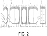
- the pouch main body 120 is configured as a so-called transverse gusset-type pouch with gusset portions formed on both side portions and, as illustrated in FIG. 1 and FIG. 2 , includes the spout attachment film 130 to which the spout 170 is attached, two side films 140 connected to the spout attachment film 130 by first connection seals 122 formed on both sides of the spout attachment film 130 in a transverse direction Xa, and a second film 150 disposed facing the spout attachment film 130 with a liquid contents accommodating portion 121 interposed therebetween and connected to the side films 140 by second connection seals 123 formed on both sides in the transverse direction Xa.
- the films 130, 140, 150, 160 are each formed as a resin film having a thermal fusing layer on at least one side thereof, and disposed so that the thermal fusing layers face each other at locations where the films are thermally fused to each other.
- thermally fused regions of the films 130, 140, 150, 160 are indicated by shading.
- the spout attachment film 130 includes a flange facing region 131 where the flange 171 of the spout 170 faces the spout attachment film 130.
- the flange facing region 131 includes a first facing region 131a that is a portion closer to a first side (upper side in the present embodiment) than a center thereof in a longitudinal direction Ya (up-down direction in the present embodiment) and a second facing region 131b that is a portion closer to a second side (lower side in the present embodiment) than the center thereof in the longitudinal direction.
- the spout attachment film 130 includes a spout through-hole 132 formed penetrating in a front-rear direction.
- the pouch main body 120 includes the first connection seal 122 formed by thermally fusing both sides of the spout attachment film 130 in the transverse direction Xa to the side films 140, the second connection seal 123 formed by thermally fusing both sides of the second film 150 in the transverse direction Xa to the side films 140, a top seal 124 formed by thermally fusing the films 140, 160 at a position corresponding to a top portion of the pouch main body 120 facing a bottom seal 125 with the liquid contents accommodating portion 121 interposed therebetween, the bottom seal 125 formed by thermally fusing the films 140, 160 at a position corresponding to the pouch bottom portion 120a of the pouch main body 120, and an intermediate seal 126 formed by thermally fusing the side films 140 and the inner side film 160.
- These seals 122 to 126 constitute bag-making sealing portions.
- connection seals 122, 123 respectively include seal base portions 122a, 123a having a strip shape extending in the longitudinal direction Ya, first inclined portions 122b, 123b formed on a first side (upper side) of the seal base portions 122a, 123a in the longitudinal direction Ya, and second inclined portions 122c, 123c formed on a second side (lower side) of the seal base portions 122a, 123a in the longitudinal direction Ya.
- the seal base portions 122a, 123a each include an inner side edge extending linearly in the longitudinal direction Ya.
- the first inclined portions 122b, 123b each include an inner side edge inclined with respect to the longitudinal direction Ya (at 45° in the present embodiment) inwardly in the transverse direction Xa toward the first side (upper side).
- the second inclined portions 122c, 123c each include an inner side edge inclined with respect to the longitudinal direction Ya (at 45° in the present embodiment) inwardly in the transverse direction Xa toward the second side (lower side).
- portions are formed in which the films 130, 140 are partially removed, and the side films 140 are thermally fused together. As a result, the side films 140 are prevented from being separated from each other at the predetermined locations described above (e.g., the locations Aa illustrated in FIG. 1 ).
- the pouch main body 120 includes first shape control sealing portions 127 as shape control sealing portions formed by fusing portions of the spout attachment film 130 positioned inward of the first connection seal 122 in the transverse direction Xa and portions of the side films 140.
- the first shape control sealing portions 127 are formed so as to continuously protrude inward in the transverse direction Xa from each first connection seal 122 (seal base portion 122a) on both sides in the transverse direction Xa with the flange facing region 131 (flange 171) interposed therebetween.
- the first shape control sealing portion 127 includes a portion positioned in a region between the flange facing region 131 and the first connection seal 122 in the transverse direction Xa, more specifically, a portion positioned in a region between the first facing region 131a on the first side (upper side) of the flange facing region 131 and the first connection seal 122 in the transverse direction Xa, and does not include a portion positioned in a region between the second facing region 131b on the second side (lower side) of the flange facing region 131 and the first connection seal 122 in the transverse direction Xa.
- first shape control sealing portions 127 formed in this way, it is possible to move the first facing region 131a side of the flange 171 fixed to the spout attachment film 130 to a pouch inner side, move the second facing region 131b side of the flange 171 to a pouch outer side, and adjust an inclination of the flange 171 so that the spout 170 faces the first side (upper side). Further, with the inclination of the flange 171 adjusted in this way, it is possible to suppress the occurrence of a buckling-induced portion that tends to be formed in the vicinity of an end portion on the second side (lower side) of the seal base portion 122a of the first connection seal 122.
- the first shape control sealing portion 127 may be formed so as to further include a portion positioned in a region between the second facing region 131b on the second side (lower side) of the flange facing region 131 and the first connection seal 122 in the transverse direction Xa in addition to the portion positioned in a region between the first facing region 131a on the first side (upper side) of the flange facing region 131 and the first connection seal 122 in the transverse direction Xa.
- the first shape control sealing portion 127 includes an innermost top portion 127a positioned innermost in the transverse direction Xa, a first inner side edge portion 127b formed continuously with a first side (upper side) of the innermost top portion 127a in the longitudinal direction Ya, and a second inner side edge portion 127c formed continuously with a second side (lower side) of the innermost top portion 127a in the longitudinal direction Ya.
- the first inner side edge portion 127b is formed at an incline outwardly in the transverse direction Xa toward the first side (upper side) in the longitudinal direction Ya.
- the second inner side edge portion 127c is formed at an incline outwardly in the transverse direction Xa toward the second side (lower side) in the longitudinal direction Ya.
- the innermost top portion 127a is formed in a dot shape (top dot shape).
- the innermost top portion 127a may be formed with a length in the longitudinal direction Ya, in other words, with an inner edge portion linearly extending in the longitudinal direction Ya.
- a curvature radius (R) of the inner edge portion in the vicinity of the innermost top portion 127a is preferably set to 20 mm or greater as a countermeasure against pouch breakage.
- the inner side edge portions 127b, 127c are each formed in a curved shape protruding inward in the transverse direction Xa, but the specific mode may be any mode.
- the inner side edge portions 127b, 127c may each be formed in a linear shape, may be formed in a curved shape protruding outward in the transverse direction Xa, or may be formed by combining one or more of the curved lines having a protruding shape or a recessed shape and the straight lines described above as desired.
- the curvature radius (R) thereof is preferably set to 20 mm or greater.
- the pouch main body 120 includes second shape control sealing portions 128 as shape control sealing portions formed by fusing portions of the spout attachment film 130 positioned inward of the first connection seal 122 in the transverse direction Xa and portions of the side films 140 in areas closer to the second side (lower side) in the longitudinal direction Ya than the first shape control sealing portions 127.
- the second shape control sealing portion 128 is formed at an interval from the first shape control sealing portion 127 in the longitudinal direction Ya.
- the second shape control sealing portions 128 are formed so as to continuously protrude inward in the transverse direction Xa from each first connection seal 122 (seal base portion 122a) on both sides of the flange facing region 131 (flange 171) in the transverse direction Xa.
- the second shape control sealing portion 128 includes a portion positioned in a region between the second facing region 131b on the second side (lower side) of the flange facing region 131 in the transverse direction Xa and the first connection seal 122, and does not include a portion positioned in a region between the first facing region 131a on the first side (upper side) of the flange facing region 131 in the transverse direction Xa and the first connection seal 122.
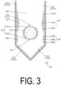
- the second shape control sealing portion 128 formed in this way, it is possible to move the first facing region 131a side of the flange 171 fixed to the spout attachment film 130 to the pouch outer side, move the second facing region 131b side of the flange 171 to the pouch inner side, and adjust the inclination of the flange 171 so that the spout 170 faces the second side (lower side).
- the second shape control sealing portions 128 may be formed so as to further include a portion positioned in a region between the first facing region 131a on the first side (upper side) of the flange facing region 131 and the first connection seal 122 in the transverse direction Xa in addition to the portion positioned in the region between the second facing region 131b on the second side (lower side) of the flange facing region 131 and the first connection seal 122 in the transverse direction Xa.
- the second shape control sealing portion 128 includes an innermost top portion 128a positioned innermost in the transverse direction Xa, a first inner side edge portion 128b formed continuously with a first side (upper side) of the innermost top portion 128a in the longitudinal direction Ya, and a second inner side edge portion 128c formed continuously with a second side (lower side) of the innermost top portion 128a in the longitudinal direction Ya.
- the first inner side edge portion 128b is formed at an incline outwardly in the transverse direction Xa toward the first side (upper side) in the longitudinal direction Ya.
- the second inner side edge portion 128c is formed at an incline outwardly in the transverse direction Xa toward the second side (lower side) in the longitudinal direction Ya.
- the innermost top portion 128a is formed in a dot shape (top dot shape).
- the innermost top portion 128a may be formed with a length in the longitudinal direction Ya, in other words, with an inner edge portion linearly extending in the longitudinal direction Ya.
- a curvature radius (R) of the inner edge portion in the vicinity of the innermost top portion 128a is preferably set to 20 mm or greater as a countermeasure against pouch breakage.
- the second shape control sealing portion 128 is formed at a predetermined interval from the first shape control sealing portion 127 in the longitudinal direction Ya.
- the first shape control sealing portion 127 and the second shape control sealing portion 128 may be formed continuously in the longitudinal direction Ya and, in this case, the shape control sealing portions 127, 128 may be formed so that an inner edge of the connecting portion of the first shape control sealing portion 127 and the second shape control sealing portion 128 is positioned inward of the first connection seal 122 (seal base portion 122a) in the transverse direction Xa.
- the inner side edge portions 128b, 128c are each formed in a curved shape protruding inward in the transverse direction Xa, but the specific mode may be any mode.
- the inner side edge portions 128b, 128c may each be formed in a linear shape, may be formed in a curved shape protruding outward in the transverse direction Xa, or may be formed by combining one or more of the curved lines having a protruding shape or a recessed shape or the straight lines described above as desired.
- the curvature radius (R) thereof is preferably set to 20 mm or greater.
- the spout 170 is formed of a synthetic resin or the like and is attached to the pouch main body 120 to function as a dispensing outlet for the liquid contents.
- the spout 170 is attached at a position closer to the second side (lower side) than a center of the spout attachment film 130 in the longitudinal direction Ya.
- the spout 170 includes a flange 171 disposed facing the spout attachment film 130 and, in the present embodiment, the flange 171 is formed as an area having a disk shape with a through-hole formed at a center thereof and an outer peripheral edge having a circular shape, and is disposed on an inner side of the pouch main body 120 and fixed to an inner side surface of the spout attachment film 130 by thermal fusing.
- FIG. 1 and FIG. 6 only a portion of the spout 170 is illustrated, and most of the spout 170 is disposed outside the pouch main body 120.
- the flange 171 includes a flange fixing portion 172 having an annular shape (circular shape in the present embodiment) and fixed to the spout attachment film 130 by thermal fusing, a flange buffering portion 173 formed in at least a partial region of an outer periphery of the flange fixing portion 172 and not fixed to the spout attachment film 130, an outer peripheral side non-fixed portion 174 formed in a partial region of the outer periphery of the flange fixing portion 172 and not fixed to the spout attachment film 130, and an inner peripheral side non-fixed portion 175 having an annular shape (circular shape in the present embodiment), set on an inner peripheral side of the flange fixing portion 172, and not fixed to the spout attachment film 130.
- a flange fixing portion 172 having an annular shape (circular shape in the present embodiment) and fixed to the spout attachment film 130 by thermal fusing
- a flange buffering portion 173 formed in at least a partial region
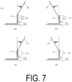
- the spout attachment film 130 bends at a location corresponding to the outer peripheral edge of the flange 171 when the spout attachment film 130 moves toward the pouch inner side relative to the flange 171, and the spout attachment film 130 bends at a location corresponding to an outer peripheral edge of the flange fixing portion 172 when the spout attachment film 130 moves toward the pouch outer side relative to the flange 171 as illustrated in FIG. 7(a) , making it possible to keep a bending load from acting on a specific location of the spout attachment film 130.
- the radial direction width Wa3 of the flange buffering portion 173 is greater than 80% of the radial direction width Wa1
- the radial direction width Wa2 of the flange fixing portion 172 becomes too narrow, the fixing strength of the flange 171 to the spout attachment film 130 cannot be sufficiently ensured, and the fixed portion readily peels off due to impact or the like, which is not desirable.
- the radial direction width Wa2 of the flange fixing portion 172 is preferably set to 2 mm or greater (more preferably 3 mm or greater) in order to ensure the fixing strength.
- a relationship between a thickness of the spout attachment film 130 and the radial direction width Wa3 of the flange buffering portion 173 is preferably such that the radial direction width Wa3 is set larger when the thickness of the spout attachment film 130 is larger.
- the flange buffering portion 173 is formed at a position including a portion of the outer periphery of the flange fixing portion 172 facing the first side (upper side) in the longitudinal direction Ya at the center in the transverse direction Xa.
- the flange buffering portion 173 is also formed at a position including a portion of the outer periphery of the flange fixing portion 172 facing the second side (lower side) in the longitudinal direction Ya at the center in the transverse direction Xa.
- the flange buffering portion 173 is formed with a radial direction width that is not constant, the flange buffering portion 173 includes a wide portion 173a that is widest in the radial direction in the flange buffering portion 173, and this wide portion 173a of the flange buffering portion 173 on the first side (upper side) is formed at a position including a portion of the outer periphery of the flange fixing portion 172 that is facing the first side (upper side) in the longitudinal direction Ya at the center in the transverse direction Xa.
- the wide portion 173a of the flange buffering portion 173 on the second side (lower side) is formed at a position including a portion of the outer periphery of the flange fixing portion 172 that is facing the second side (lower side) in the longitudinal direction Ya at the center in the transverse direction Xa.
- the wide portion 173a of the flange buffering portion 173 on the first side (upper side) and the wide portion 173a of the flange buffering portion 173 on the second side (lower side) are formed to the same radial direction widths, but may be formed to different radial direction widths.
- the flange fixing portion 172 is set in an area of the flange 171 where the thickness on the outer peripheral side is thinly formed.
- the outer peripheral side non-fixed portion 174 is a portion of the outer periphery of the flange fixing portion 172 that is not fixed to the spout attachment film 130, does not exhibit the above-described effect of the flange buffering portion 173 (effect of keeping a bending load from acting on a specific location of the spout attachment film 130), and is formed with a narrower radial direction width than that of the flange buffering portion 173.
- the outer peripheral non-fixed portion 174 functions as an area that suppresses leakage (protrusion) of the adhesive outside the outer peripheral edge of the flange 171 and prevents the spout attachment film 130 from being fixed to the flange 171 in a state in which the spout attachment film 130 is wrinkled in the vicinity of the outer peripheral edge of the flange 171.
- the flange buffering portion 173 is described as being formed at two locations, namely on the first side (upper side) and on the second side (lower side) of the outer periphery of the flange fixing portion 172, but the specific mode of the flange buffering portion 173 is not limited thereto, and the flange buffering portion 173 may be formed in any desired mode in accordance with the embodiment.
- the flange buffering portion 173 may be formed at only one of the two locations of the first side (upper side) and the second side (lower side) of the outer periphery of the flange fixing portion 172, or the flange buffering portion 173 may be formed across the entire outer periphery of the flange fixing portion 172 as illustrated in FIG. 8(a) .
- the flange buffering portion 173 is formed with a uniform radial direction width across the entire outer periphery of the flange fixing portion 172.
- FIG. 8(a) the flange buffering portion 173 is formed with a uniform radial direction width across the entire outer periphery of the flange fixing portion 172.
- a region in which the outer peripheral side non-fixed portion 174 is not formed (that is, a region fixed to the spout attachment film 130 up to the outer peripheral edge of the flange 171) may be formed in a partial region of the outer periphery of the flange fixing portion 172.
- the flange 171 of the spout 170 has been described as being formed in a flat plate shape.
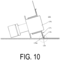
- the flange buffering portion 173 includes the retracted portion 176 with an outer peripheral side tip portion positioned on a side (right side in FIG. 9 ) farther away from the spout attachment film 130 than the flange fixing portion 172 in a thickness direction.
- the retracted portion 176 is formed by curving the outer peripheral side of the flange 171 away from the spout attachment film 130 (right side in FIG. 9 ), and includes a curved surface 176a that curves toward the side away from the spout attachment film 130 (right side in FIG. 9 ) toward the outer peripheral side, on the side facing the spout attachment film 130.
- the curved surface 176a curves, forming a protruding shape toward the side facing the spout attachment film 130 (left side in FIG. 9 ).
- the retracted portion 176 may be formed in an annular shape across the entire periphery of the outer peripheral portion of the flange 171, or may be formed only in a partial region of the outer peripheral portion of the flange 171. Further, in a case in which the retracted portion 176 is formed only in a partial region of the outer peripheral portion of the flange 171, the retracted portion 176 may be formed at a plurality of locations separated in the peripheral direction.
- a dimensional (width) relationship and a positional relationship between the flange buffering portion 173 and the retracted portion 176 in the peripheral direction need only be such that the dimensions (widths) and the positions of the flange buffering portion 173 and the retracted portion 176 in the peripheral direction are set so that the flange buffering portion 173 and the retracted portion 176 overlap each other in the peripheral direction in at least a partial region of the outer peripheral portion of the flange 171.
- a radial direction dimension relationship between the flange buffering portion 173 and the retracted portion 176 may be set so that the dimensions (widths) in the radial direction of the flange buffering portion 173 and the retracted portion 176 coincide with each other as illustrated in FIG. 11(a)
- the dimension (width) in the radial direction of the retracted portion 176 may be set larger than that of the flange buffering portion 173 as illustrated in FIG. 11(b)
- the dimension (width) in the radial direction of the retracted portion 176 may be set smaller than that of the flange buffering portion 173 as illustrated in FIG. 11(c) .
- an outer peripheral edge position of the flange buffering portion 173 and an outer peripheral edge position of the retracted portion 176 coincide with each other.
- the retracted portion 176 has a shape in which the outer peripheral side of the flange 171 is curved to the side away from the spout attachment film 130 (right side in FIG. 9 ), but the specific shape of the retracted portion 176 may be any shape as long as the outer peripheral side tip end portion of the flange fixing portion 172 is positioned away from the spout attachment film 130 (right side in FIG. 9 ).
- the retracted portion 176 may be formed in a shape in which the flange 171 is not curved but the flange 171 is bent in the middle in the radial direction.
- the inner side film 160 is formed as a resin film having a rectangular shape (or substantially rectangular shape) and flexibility with a thermal fusing layer on at least one side thereof and, as understood from FIG. 1 and FIG. 2 , is disposed in the pouch main body 120 (liquid contents accommodating portion 121) in a state of being folded in two, and a predetermined portion thereof is thermally fused to the side film 140.
- the inner side film 160 is formed with a plurality of film penetrating portions formed in hole shapes penetrating in the film thickness direction.
- a handle hole 129 for a user to hold the spout pouch 110 by passing his or her hand or finger therethrough is formed through the overlapping portion of the films 140, 160.
- a transverse direction dimension ba1 from the first connection seal 122 (seal base portion 122a) to the innermost top portion 127a of the first shape control sealing portion 127 is preferably set to 6 to 10% of a transverse direction interval aa to the first connection seal 122 (seal base portion 122a) in the transverse direction Xa.
- the transverse direction dimension ba1 is preferably set to 20 to 50% of a transverse direction dimension ca from the first connection seal 122 (seal base portion 122a) to, of the outer peripheral edge of the flange facing region 131 (flange 171), a location 131c positioned on the outermost side (first connection seal 122 side) in the transverse direction Xa.
- the effects of forming the first shape control sealing portion 127 (the effect of deepening the spout attachment film 130 in the vicinity of the outer peripheral edge of the flange 171 toward the pouch inner side, the effect of alleviating the tension of the spout attachment film 130 in the vicinity of the outer peripheral edge of the flange 171, and the effect of adjusting the inclination of the flange 171) while avoiding excessive restraint of the movement of the spout 170 by the spout attachment film 130.
- a transverse direction dimension ba2 from the first connection seal 122 (seal base portion 122a) to the innermost top portion 128a of the second shape control sealing portion 128 is set to 4 to 10% of the transverse direction interval aa.
- transverse direction dimension ba2 is preferably set to 10 to 50% of the transverse direction dimension ca.
- the effects of forming the second shape control sealing portion 128 (the effect of deepening the spout attachment film 130 in the vicinity of the outer peripheral edge of the flange 171 toward the pouch inner side, the effect of alleviating the tension of the spout attachment film 130 in the vicinity of the outer peripheral edge of the flange 171, and the effect of adjusting the inclination of the flange 171) while avoiding excessive restraint of the movement of the spout 170 by the spout attachment film 130.
- transverse direction dimension ba1 is preferably set to the transverse direction dimension ba2 or greater.
- transverse direction dimension ba2 is preferably set to 30% or more of the transverse direction dimension ba1.
- the inclination of the spout 170 can be favorably adjusted, that is, the inclination of the spout 170 toward the first side (upper side) or the second side (lower side) in the longitudinal direction Ya can be favorably adjusted.
- a longitudinal direction position of the innermost top portion 127a of the first shape control sealing portion 127 is preferably set within a range of ⁇ 10 mm in the longitudinal direction Ya from the longitudinal direction position of a location 131d of the outer peripheral edge of the flange facing region 131 (flange 171) positioned closest to the first side (upper side) in the longitudinal direction Ya.
- the longitudinal direction position of the innermost top portion 127a of the first shape control sealing portion 127 is shifted to either the first side (upper side) or the second side (lower side) from the longitudinal direction position of the location 131d.
- a longitudinal direction position of an end portion (lower end) on the second side (lower side) of the first shape control sealing portion 127 (second inner side edge portion 127c) is preferably set at a position lateral of the flange facing region 131 (flange 171) in the transverse direction Xa, more preferably within a range of ⁇ 10 mm in the longitudinal direction Ya from a center position of the flange facing region 131 (flange 171) in the longitudinal direction Ya, and more preferably set to coincide with the center position of the flange facing region 131 (flange 171) in the longitudinal direction Ya.
- a longitudinal direction position of an end portion (upper end) on the first side (upper side) of the second shape control sealing portion 128 (first inner side edge portion 128b) is set lower than the center position of the flange facing region 131 (flange 171) in the longitudinal direction Ya.
- the spout attachment film 130 (first connection seal 122) is folded starting from the lower end portions of the second shape control sealing portions 128 (the second inner side edge portions 128c) on both sides in the transverse direction Xa.
- a longitudinal direction position of the end portion (upper end) on the first side (upper side) of the second shape control sealing portion 128 (first inner side edge portion 128b) is more preferably set to a position located lateral of the flange facing region 131 (second facing region 131b) in the transverse direction Xa, as illustrated in FIG. 5(a) .
- the spout attachment film 130 and the spout 170 are guided to the state shown in FIG. 5(b) , making it possible to prevent the spout 170 from retracting to the pouch inner side and causing a strong force to act on the spout 170 due to contact with the floor or the like.
- a longitudinal direction dimension sa (longitudinal direction dimension sa of the first inner side edge portion 127b) from the innermost top portion 127a of the first shape control sealing portion 127 to an end portion (upper end) on the first side (upper side) of the first shape control sealing portion 127 (first inner side edge portion 127b) is preferably set larger than a longitudinal direction dimension ta (longitudinal direction dimension ta of the second inner side edge portion 127c) from the innermost top portion 127a of the first shape control sealing portion 127 to the end portion (lower end) on the second side (lower side) of the first shape control sealing portion 127 (second inner side edge portion 127c).
- the longitudinal direction dimension sa and the transverse direction dimension ba1 are preferably set so that an angle between the first connection seal 22 and a virtual line connecting the innermost top portion 127a of the first shape control sealing portion 127 (end portion on the first side of the innermost top portion 127a in a case in which the innermost top portion 127a is formed with a length in the longitudinal direction Ya) and the end portion (upper end) on the first side (upper side) of the first shape control sealing portion 127 (first inner side edge portion 127b) is 5 to 10°.
- a longitudinal direction position of the innermost top portion 128a of the second shape control sealing portion 128 (longitudinal direction position of an end portion on the first side of the innermost top portion 128a in a case in which the innermost top portion 127a is formed with a length in the longitudinal direction Ya) is preferably set within a range of ⁇ 5 mm in the longitudinal direction Ya from the longitudinal direction position of a location 131e of the outer peripheral edge of the flange facing region 131 (flange 171) positioned closest to the second side (lower side) in the longitudinal direction Ya (or from a location of the outer peripheral edge of the flange fixing portion 172 positioned closest to the second side in the longitudinal direction Ya).
- the longitudinal direction position of the innermost top portion 128a of the second shape control sealing portion 128 is preferably shifted to either the first side (upper side) or the second side (lower side) from the longitudinal direction position of the location 131e.
- the spout attachment film 130 and the spout 170 can be smoothly guided to the state shown in FIG. 5(b) described above.
- a longitudinal direction position of an end portion (lower end) on the second side (lower side) of the second shape control sealing portion 128 (second inner side edge portion 128c) is preferably set on the first side (upper side) of the second inclined portion 122c of the first connection seal 122.
- the second shape control sealing portion 128 is a portion constituting the pouch bottom portion 120a.
- the second shape control sealing portion 128 is a portion constituting the pouch bottom portion 120a.
- spout pouch 110 may be configured by any combination of configurations of the embodiment described above and modified examples to be described below.
- the spout pouch 110 is described as being accommodated and utilized in the outer case (not illustrated) during usage, during display, or during transport, but the spout pouch 110 itself may be used or may be displayed or transported without being accommodated in the outer case (not illustrated).
- each film includes a layer having thermal fusing properties, such as an olefin-based layer made of low density polyethylene or polypropylene or a polyester-based layer made of polyethylene terephthalate (PET), or the like on at least one of the surfaces thereof
- a film including a single film of the thermal fusing layer may be used, or any desired layer may be layered to the thermal fusing layer.
- Any material may be used as a material constituting the multilayer, and the multilayer may be formed as desired by layering a known polyester such as PET or polybutylene terephthalate (PBT), polypropylene, polyamide, polyethylene, aluminum foil, or the like.
- the pouch main body 120 is described as being formed of four films, namely the films 130, 140, 150.
- a specific mode of the pouch main body 120 such as the number of films constituting the pouch main body 120, is not limited to the above and, for example, a gusset film for the bottom portion may be separately provided at a position corresponding to the pouch bottom portion 120a.
- the inner side film 160 need not be provided.
- the spout pouch 110 is configured as a large-capacity pouch having a volume of 2 to 5 L
- the spout 170 is configured as a large spout with an outer diameter of the flange 171 being 50 to 70 mm.
- the sizes of the spout pouch 110 and the spout 170 are not limited thereto and may be set as desired in accordance with the embodiment.
- the spout attachment film 130 to which the spout 170 is attached is described as a gusset film constituting a gusset portion of a transverse gusset-type pouch.
- a specific mode of the spout attachment film 130 is not limited thereto and, for example, the spout attachment film 130 may be a gusset film disposed on a top portion or a bottom portion of the pouch, or the spout attachment film 130 may be a film other than a gusset film.
- the shape control sealing portions 127, 128 are described as being formed continuously with the first connection seal 122. However, the shape control sealing portions 127, 128 may be formed independently of (at positions separated from) the first connection seal 122.
- first shape control sealing portion 127 is described as being formed on each of both sides of the flange facing region 131, but the first shape control sealing portion 127 may be formed on only one of both sides of the flange facing region 131 in the transverse direction Xa.
- second shape control sealing portion 128 may be formed on only one of both sides of the flange facing region 131 in the transverse direction Xa.
- the shape control sealing portions 127, 128 on both sides in the transverse direction Xa are formed in line symmetry (left-right symmetry) with respect to a virtual line extending in the longitudinal direction Ya at the center of the spout attachment film 130 in the transverse direction Xa, but the configuration is not limited thereto.
- the first connection seals 122 on both sides in the transverse direction Xa are formed in line symmetry (left-right symmetry) with respect to the virtual line, but are not limited thereto.
- the first shape control sealing portion 127 and the second shape control sealing portion 128 are described as being formed. However, only the first shape control sealing portion 127 may be formed without forming the second shape control sealing portion 128. Note that, in a case in which only the first shape control sealing portion 127 is formed, the dimensional relationship of each portion related to the first shape control sealing portion 127 is the same as that described above with reference to FIG. 4 . Alternatively, only the second shape control sealing portion 128 may be formed without forming the first shape control sealing portion 127. Note that, in a case in which only the second shape control sealing portion 128 is formed, the dimensional relationship of each portion related to the second shape control sealing portion 128 is the same as that described above with reference to FIG. 4 .
- the flange 171 is described as being formed in a disk shape with an outer peripheral edge having a circular shape.
- the specific shape of the flange 171 may be any shape such as a shape having an outer peripheral edge of a shape other than a circular shape, such as a rectangular shape or a polygonal shape.
- the flange 171 is described as being fixed to the inner side surface of the spout attachment film 130. However, the flange 171 may be fixed to the outer side surface of the spout attachment film 130.
- the flange 171 may be fixed to the spout attachment film 130 by any method other than thermal fusing, such as adhesion.
- the flange 171 is described as being provided with the flange buffering portion 173.
- the flange 171 may be fixed to the spout attachment film 130 in any manner, the flange 171 may not be provided with the flange buffering portion 173 and, for example, the entire region of the flange 171 may be fixed to the spout attachment film 130.
- first shape control sealing portion 127 and the second shape control sealing portion 128 are described as being formed in the first connection seal 122. However, the shape control sealing portions 127, 128 need not be formed.
- top portion bottom portion
- side portion side portion
- up and down directions are used herein, but these terms do not limit the orientation of the placement of the spout pouch 110 during display, during transport, and the like.
- the spout pouch 110 may be placed on the placement surface with the side portion or the top portion of the spout pouch 110 down during display, during transport, and the like.
- the spout pouch 210 accommodates liquid contents, such as drinking water or a liquid detergent, and is configured to dispense the liquid contents from a spout 280 attached to a side surface of a pouch main body 220 as illustrated in FIG. 12 and FIG. 18 .
- the spout pouch 210 includes the pouch main body 220 formed into a bag shape by thermally fusing films 230, 240, 250, 260 having flexibility to form bag-making sealing portions, an inner side film 270 disposed inside the pouch main body 220, and the spout 280 attached to the pouch main body 220.
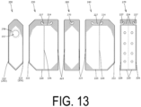
- the pouch main body 220 is configured as a so-called transverse gusset-type pouch with gussets formed on both side portions and, as illustrated in FIG. 12 and FIG. 13 , includes the front side film 230 and the rear side film 240 disposed facing each other in a front-rear direction Xb with a liquid contents accommodating portion 221 interposed therebetween, the side gusset film 250 disposed between the front side film 230 and the rear side film 240 of one pouch side portion and thermally fused to the front side film 230 and the rear side film 240 by a first side seal 222, and the second gusset film 260 disposed facing the side gusset film 250 in a front-back direction Zb with the liquid contents accommodating portion 221 interposed therebetween and thermally fused to the front side film 230 and the rear side film 240 by a second side seal 223 of the other pouch side portion.
- the films 230, 240, 250, 260, 270 are each formed as a resin film having a thermal fusing layer on at least one side thereof, and disposed so that the thermal fusing layers face each other at locations where the films are thermally fused to each other.
- thermally fused regions of the films 230, 240, 250, 260, and 270 are indicated by shading.
- the pouch main body 220 includes the first side seal 222 formed by thermally fusing both sides of the side gusset film 250 in the transverse direction to the films 230, 240, the second side seal 223 formed by thermally fusing both sides of the second gusset film 260 in the transverse direction to the films 230, 240, a top seal 224 formed by thermally fusing the films 230, 240, 260 at a position corresponding to a top portion of the pouch main body 220 facing a bottom seal 225 with the liquid contents accommodating portion 221 interposed therebetween, the bottom seal 225 formed by thermally fusing the films 230, 240, 260 at a position corresponding to a pouch bottom portion 220a of the pouch main body 220, and an intermediate seal 226 formed by thermally fusing the films 230, 240 and the inner side film 270.
- These seals 222 to 226 constitute bag-making sealing portions.
- portions are formed where the second gusset film 260 is partially removed, and the films 230, 240 are thermally fused together. As a result, the films 230, 240 are prevented from being separated from each other at the predetermined locations (e.g., locations A illustrated in FIG. 12 ).
- the side gusset film 250 includes a front side sealing region 251 thermally fused to the front side film 230 at the first side seal 222, a rear side sealing region 252 thermally fused to the rear side film 240 at the first side seal 222, and a non-sealing region 253 that is a region on an inner side of the front side sealing region 251 and the rear side sealing region 252.
- the non-sealing region 253 includes a front side outer edge 254 that is a boundary with the front side sealing region 251, and a rear side outer edge 255 that is a boundary with the rear side sealing region 252.
- the side gusset film 250 is formed in line symmetry (left-right symmetry) with respect to a virtual line extending in an up-down direction Yb at a center of the side gusset film 250 in the front-rear direction Xb.
- the front side outer edge 254 and the rear side outer edge 255 are formed in line symmetry (left-right symmetry) with respect to the virtual line.
- the front side outer edge 254 and the rear side outer edge 255 include base edge portions 254a, 255a spaced apart from each other in the front-rear direction Xb, lower side inclined edge portions 254b, 255b extending from lower ends of the base edge portions 254a, 255a to a lower end coupling portion 253a coupling lower ends of the front side outer edge 254 and the rear side outer edge 255, and upper side inclined edge portions 254c, 255c extending from the upper ends of the base edge portions 254a, 255a to an upper end coupling portion 253b coupling upper ends of the front side outer edge 254 and the rear side outer edge 255.
- the base edge portions 254a, 255a are formed linearly extending in the up-down direction Yb.
- the lower side inclined edge portions 254b, 255b extend linearly at an incline in the up-down direction Yb inwardly in the front-rear direction Xb (at an inclination angle of 45° in the present embodiment) toward the lower side.
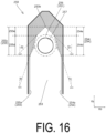
- the upper side inclined edge portions 254c, 255c are constituted by at least two inclined portions having different inclination angles relative to the up-down direction Yb and, in the present embodiment, as illustrated in FIG. 15 , include gently inclined portions 254d, 255d that connect the upper ends of the base edge portions 254a, 255a with portions above and inward, in the front-rear direction Xb, of the upper ends of the base edge portions 254a, 255a, and steeply inclined portions 254e, 255e that connect upper ends of the gently inclined portions 254d, 255d with the upper end coupling portion 253b.
- each of the gently inclined portions 254d, 255d is constituted by one linear portion extending at an incline in the up-down direction Yb inwardly in the front-rear direction Xb toward the upper side
- each of the steeply inclined portions 254e, 255e is constituted by one linear portion extending at an incline in the up-down direction Yb inwardly in the front-rear direction Xb toward the upper side (at an inclination angle of 45° in the present embodiment).
- first virtual lines Lb 1 passing through the upper ends and the lower ends of the gently inclined portions 254d, 255d extend at an incline in the up-down direction Yb inwardly in the front-rear direction Xb toward the upper side.
- second virtual lines Lb2 passing through upper and lower ends of the steeply inclined portions 254e, 255e extend at an incline in the up-down direction Yb inwardly in the front-rear direction Xb toward the upper side.
- an inclination angle ⁇ 1 of the first virtual line Lb 1 with respect to the up-down direction Yb is smaller than an inclination angle ⁇ 2 of the second virtual line Lb2 with respect to the up-down direction Yb.
- a degree of extending inwardly in the front-rear direction Xb toward the upper side is stronger (greater) for the second virtual lines Lb2 (steeply inclined portions 254e, 255e) than for the first virtual lines Lb 1 (gently inclined portions 254d, 255d).
- the side gusset film 250 includes a flange facing region 256 where a flange 281 of the spout 280 faces the side gusset film 250.
- the flange facing region 256 is formed in an annular shape with an outer peripheral edge having a circular shape.
- the side gusset film 250 includes a spout through-hole 257 having a circular shape, formed so as to penetrate in the film thickness direction, and through which a dispensing cylindrical portion 282 of the spout 280 is inserted.
- the spout 280 is formed of a synthetic resin or other material, is attached to the pouch main body 220 to serve as a dispensing outlet for the liquid contents and, as illustrated in FIG. 12 and FIG. 18 , and includes the flange 281 disposed facing the side gusset film 250, the dispensing cylindrical portion 282 extending perpendicularly to the flange 281 having a disk shape and including a dispensing hole 282a formed therein, and a cap 283 detachably attached to a tip end of the dispensing cylindrical portion 282.
- the flange 281 is formed as an area having a disk shape (annular shape) with a through-hole formed at a center thereof and an outer peripheral edge having a circular shape (flange outer peripheral edge), is disposed on an inner side of the pouch main body 220, and is at least partially fixed to an inner side surface of the side gusset film 250 by thermal fusing.
- FIG. 12 illustrates only the flange 281 of the spout 280 and, as illustrated in FIG. 18 , most of the spout 280, such as the dispensing cylindrical portion 282 and the cap 283, is disposed outside the pouch main body 220.
- At least a portion (major portion in the example illustrated in FIG. 15 ) of the flange 281 (flange facing region 256) including a center of the flange 281 (flange facing region 256) is disposed facing a region between the upper side inclined edge portion 254c of the front side outer edge 254 and the upper side inclined edge portion 255c of the rear side outer edge 255, and more particularly, disposed facing a region between the gently inclined portion 254d of the front side outer edge 254 and the gently inclined portion 255d of the rear side outer edge 255.
- the flange 281 (flange facing region 256) is disposed at a center of the side gusset film 250 in the front-rear direction Xb, and an interval between the front side outer edge 254 and an outer edge of the flange 281 (flange facing region 256) and an interval between the rear side outer edge 255 and the outer edge of the flange 281 (flange facing region 256) in the front-rear direction Xb are equal.
- the region between the upper side inclined edge portion 254c of the front side outer edge 254 and the upper side inclined edge portion 255c of the rear side outer edge 255 to which the flange 281 is (at least partially) attached as described above is a portion inclined inwardly of the pouch main body 220 in the front-back direction Zb toward the upper side when viewed in the front-rear direction Xb in a state in which the spout pouch 210 is placed on a placement surface with the pouch bottom portion 220a down. Therefore, in a state in which the spout pouch 210 is placed on the placement surface, as understood from FIG. 12 and FIG.
- the dispensing cylindrical portion 282 of the spout 280 attached to the region described above is at an upward incline, extending obliquely with respect to the up-down direction Yb (and the front-back direction Zb), in other words, is inclined outwardly of the pouch main body 220 in the front-back direction Zb toward the upper side.
- the inner side film 270 is formed as a resin film having a rectangular shape (or substantially rectangular shape) and flexibility with a thermal fusing layer on at least one side thereof and, as understood from FIG. 12 and FIG. 13 , is disposed in the pouch main body 220 (liquid contents accommodating portion 221) in a state of being folded in two, and a predetermined portion thereof is thermally fused to the films 230, 240.
- the inner side film 270 is formed with a plurality of film penetrating portions formed in hole shapes penetrating in the film thickness direction.
- a handle hole 227 for a user to hold the spout pouch 210 by passing his or her hand or finger therethrough is formed through the overlapping portion of the films 230, 240, 260.
- FIG. 13 illustrates the handle hole 227 being formed in a state in which the films 230, 240, 260 are not thermally fused to one another for convenience of technical understanding.
- the handle hole 227 is formed by punching at a predetermined location after the films 230, 240, 260 are thermally fused to one another.
- the liquid contents accommodating portion 221 of the spout pouch 210 are accommodated in an amount equal to or less than the volume of a portion below a virtual line Lb3 obtained by extending a lower end edge of an inner peripheral surface of the dispensing hole 282a of the spout 280 (specifically, the lower end edge of the inner peripheral surface of the dispensing hole 282a on a tip end side of the dispensing cylindrical portion 282) of the liquid contents accommodating portion 221 in the extending direction of the lower end edge when the top seal 224 (pouch top portion side), including the handle hole 227 formed therein, is supported (held) and the spout pouch 210 accommodating the liquid contents in the liquid contents accommodating portion 221 is lifted up in an unopened state (liquid contents have not yet been dispensed), as viewed in the front-rear direction Xb.
- FIG. 18(a) illustrates a state in which the liquid contents accommodating portion 221 accommodates the same amount of
- the spout pouch 210 By setting the amount of the liquid contents accommodated in the liquid contents accommodating portion 221 in this way, it is possible to tilt and lift the spout pouch 210 so that the dispensing cylindrical portion 282 of the spout 280 is facing sideways (by holding the pouch top portion side with the handle hole 227 formed therein or the like) and make the dispensing cylindrical portion 282 extend in a horizontal direction or make the dispensing cylindrical portion 282 incline downward (that is, incline downward from the horizontal direction) when dispensing the liquid contents, as in the posture illustrated in FIG. 18(a) .
- an inclination angle of the flange 281 with respect to the up-down direction Yb of the pouch main body 220 by reducing an inclination angle of the region of the side gusset film 250 to which the flange 281 is attached (region between the gently inclined portions 254d, 255d) with respect to the up-down direction Yb, thereby adjusting the extending direction of the dispensing cylindrical portion 282 of the spout 280 (direction in which the virtual line Lb3 extends) downward (closer to a direction perpendicular to the up-down direction Yb).
- the gently inclined portions 254d, 255d are described as being constituted by one linear portion extending at an incline in the up-down direction Yb, but the specific mode of the gently inclined portions 254d, 255d is not limited thereto, and the gently inclined portions 254d, 255d may each be constituted by at least one linear portion, at least one curved portion, or a combination thereof.
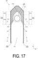
- each of the gently inclined portions 254d, 255d includes a plurality of (three) linear portions, that is, a first linear portion extending at an incline in the up-down direction Yb inwardly in the front-rear direction Xb toward the upper side from the upper end of the base edge portion 254a, 255a, a second linear portion extending in the up-down direction Yb from an upper end of the first linear portion, and a third linear portion extending at an incline in the up-down direction Yb inwardly in the front-rear direction Xb toward the upper side from an upper end of the second linear portion.
- each of the gently inclined portions 254d, 255d is constituted by a plurality of (three) linear portions, that is, a first linear portion extending at an incline in the up-down direction Yb inwardly in the front-rear direction Xb toward the upper side from the upper end of the base edge portion 254a, 255a, a second linear portion extending at an incline in the up-down direction Yb outwardly in the front-rear direction Xb toward the upper side from the upper end of the first linear portion, and a third linear portion extending at an incline in the up-down direction Yb inwardly in the front-rear direction Xb toward the upper side from the upper end of the second linear portion.
- the linear portions (or curved portions) constituting the gently inclined portions 254d, 255d may extend at an incline in the up-down direction Yb inwardly in the front-rear direction Xb toward the upper side, may extend in the up-down direction Yb, may extend at an incline in the up-down direction Yb outwardly in the front-rear direction Xb toward the upper side, or the like.
- each of the steeply inclined portions 254e, 255e are constituted by one linear portion extending at an incline in the up-down direction Yb, but the specific mode of the steeply inclined portions 254e, 255e is not limited thereto, and the steeply inclined portions 254e, 255e may each be constituted by at least one linear portion, at least one curved portion, or a combination thereof.
- At least one of the front side sealing region 251 and the rear side sealing region 252 includes control sealing portions 251a, 252a positioned inward of the first virtual line L1 in the front-rear direction Xb.
- control sealing portions 251a, 252a are each formed so as to include a portion positioned in a region between a lower half of the flange facing region 256 (flange 281) and the front side sealing region 251 or the rear side sealing region 252 in the front-rear direction Xb, and not include a portion positioned above a center of the flange facing region 256 (flange 281) in the up-down direction Yb.
- each of the control sealing portions 251a, 252a positioned most inward in the front-rear direction Xb is positioned in a region between the lower half of the flange facing region 256 (flange 281) and the front side sealing region 251 or the rear side sealing region 252 in the front-rear direction Xb.
- control sealing portions 251a, 252a each include an area positioned below the flange facing region 256 (flange 281).
- spout pouch 210 may be configured by any combination of configurations of the embodiment described above and modified examples described below.
- the spout pouch 210 may be accommodated and utilized in the outer case (not illustrated) during usage, during display, or during transport thereof, and the spout pouch 210 itself may be used, displayed, or transported, without being accommodated in the outer case (not illustrated).
- each film includes a layer having thermal fusing properties, such as an olefin-based layer made of low density polyethylene or polypropylene or a polyester-based layer made of polyethylene terephthalate (PET), or the like on at least one of the surfaces thereof, a film including a single film of the thermal fusing layer may be used, or any desired layer may be layered to the thermal fusing layer.
- a layer having thermal fusing properties such as an olefin-based layer made of low density polyethylene or polypropylene or a polyester-based layer made of polyethylene terephthalate (PET), or the like
- PET polyethylene terephthalate
- any material may be used as a material constituting the multilayer, and the multilayer may be formed as desired by layering a known polyester such as PET or polybutylene terephthalate (PBT), polypropylene, polyamide, polyethylene, aluminum foil, or the like.
- PET polybutylene terephthalate
- PBT polybutylene terephthalate
- polypropylene polypropylene
- polyamide polyamide
- polyethylene polyethylene
- aluminum foil or the like.
- the pouch main body 220 is described as being formed of four films, namely the films 230, 240, 250 260.
- a specific mode of the pouch main body 220 such as the number of films constituting the pouch main body 220, is not limited to the above and, for example, a gusset film for the bottom portion may be separately provided at a position corresponding to the pouch bottom portion 220a.
- the inner side film 270 need not be provided.
- the spout pouch 210 is configured as a large-capacity pouch having a volume of 2 to 5 L
- the spout 280 is configured as a large spout with an outer diameter of the flange 281 being 50 to 70 mm.
- the sizes of the spout pouch 210 and the spout 280 are not limited thereto and may be set as desired in accordance with the embodiment.
- the front side outer edge 254 and the rear side outer edge 255 are described as being formed in line symmetry (left-right symmetry) with respect to the virtual line extending in the up-down direction Yb at the center of the side gusset film 250 in the front-rear direction Xb.
- the front side outer edge 254 and the rear side outer edge 255 may be formed not in left-right symmetry.
- control sealing portions 251a, 252a are formed continuously with the sealing regions 251, 252.
- control sealing portions 251a, 252a may be formed independently of (at positions separated from) the sealing regions 251, 252.
- the flange 281 is described as being formed in a disk shape with an outer peripheral edge having a circular shape.
- the specific shape of the flange 281 may be any shape such as a shape having an outer peripheral edge (flange outer peripheral edge) of a shape other than a circular shape, such as a rectangular shape or a polygonal shape.
- the flange 281 is described as being fixed to the inner side surface of the side gusset film 250.
- the flange 281 may be fixed to an outer side surface of the side gusset film 250.
- the flange 281 may be fixed to the side gusset film 250 by any method other than thermal fusing, such as adhesion.
- top portion bottom portion
- side portion side portion
- up and down directions are used herein, but these terms do not limit the orientation of the placement of the spout pouch 210 during display, during transport, and the like.
- the spout pouch 210 may be placed on the placement surface with the side portion or the top portion of the spout pouch 210 down during display, during transport, and the like.
- the liquid contents are described as being dispensed in a state in which the pouch top portion side is held and the spout pouch 210 is lifted, but the specific mode of dispensing the liquid contents is not limited to the above.
- the liquid contents may be dispensed in a state in which the spout pouch 210 is lifted by supporting and holding a portion other than the pouch top portion side such as the pouch bottom portion 220a, or the liquid contents may be dispensed in a state in which the spout pouch 210 is placed on a placement surface.
- a spout pouch comprising:
- the spout pouch according to Aspect 2 wherein the first shape control sealing portion further includes a portion positioned in a region between the second facing region and the connection seal in the transverse direction.
- a spout pouch comprising:
- flange buffering portion is an area having a radial direction width formed to 650% or more of a thickness of the spout attachment film.
- the flange buffering portion includes a retracted portion including an outer peripheral side tip end portion positioned on a side away from the spout attachment film.
Landscapes
- Engineering & Computer Science (AREA)
- Mechanical Engineering (AREA)
- Bag Frames (AREA)
- Packages (AREA)
Applications Claiming Priority (5)
| Application Number | Priority Date | Filing Date | Title |
|---|---|---|---|
| JP2021189648A JP7476869B2 (ja) | 2021-11-22 | 2021-11-22 | スパウト付きパウチ |
| JP2021189647A JP7476868B2 (ja) | 2021-11-22 | 2021-11-22 | スパウト付きパウチ |
| JP2021191650A JP7505475B2 (ja) | 2021-11-26 | 2021-11-26 | スパウト付きパウチ |
| PCT/JP2022/042695 WO2023090393A1 (ja) | 2021-11-22 | 2022-11-17 | スパウト付きパウチ |
| EP22895674.4A EP4438514A4 (de) | 2021-11-22 | 2022-11-17 | Beutel mit ausguss |
Related Parent Applications (2)
| Application Number | Title | Priority Date | Filing Date |
|---|---|---|---|
| EP22895674.4A Division-Into EP4438514A4 (de) | 2021-11-22 | 2022-11-17 | Beutel mit ausguss |
| EP22895674.4A Division EP4438514A4 (de) | 2021-11-22 | 2022-11-17 | Beutel mit ausguss |
Publications (2)
| Publication Number | Publication Date |
|---|---|
| EP4516691A2 true EP4516691A2 (de) | 2025-03-05 |
| EP4516691A3 EP4516691A3 (de) | 2025-05-14 |
Family
ID=86397156
Family Applications (3)
| Application Number | Title | Priority Date | Filing Date |
|---|---|---|---|
| EP22895674.4A Pending EP4438514A4 (de) | 2021-11-22 | 2022-11-17 | Beutel mit ausguss |
| EP25150809.9A Pending EP4516691A3 (de) | 2021-11-22 | 2022-11-17 | Ausgussbeutel |
| EP25150811.5A Pending EP4552996A1 (de) | 2021-11-22 | 2022-11-17 | Ausgussbeutel |
Family Applications Before (1)
| Application Number | Title | Priority Date | Filing Date |
|---|---|---|---|
| EP22895674.4A Pending EP4438514A4 (de) | 2021-11-22 | 2022-11-17 | Beutel mit ausguss |
Family Applications After (1)
| Application Number | Title | Priority Date | Filing Date |
|---|---|---|---|
| EP25150811.5A Pending EP4552996A1 (de) | 2021-11-22 | 2022-11-17 | Ausgussbeutel |
Country Status (4)
| Country | Link |
|---|---|
| US (1) | US20240300718A1 (de) |
| EP (3) | EP4438514A4 (de) |
| TW (1) | TW202334002A (de) |
| WO (1) | WO2023090393A1 (de) |
Citations (2)
| Publication number | Priority date | Publication date | Assignee | Title |
|---|---|---|---|---|
| JP2012121611A (ja) | 2010-12-09 | 2012-06-28 | Fujimori Kogyo Co Ltd | 充填用容器 |
| JP2020132177A (ja) | 2019-02-15 | 2020-08-31 | 東洋製罐株式会社 | マチ付きパウチおよびマチ付きパウチの製造方法 |
Family Cites Families (13)
| Publication number | Priority date | Publication date | Assignee | Title |
|---|---|---|---|---|
| JPS6013370U (ja) * | 1983-07-06 | 1985-01-29 | ユニチカ株式会社 | 大型容器 |
| JPH0335049U (de) * | 1989-08-10 | 1991-04-05 | ||
| JP3245031B2 (ja) * | 1994-11-18 | 2002-01-07 | 株式会社細川洋行 | バッグインボックス用袋体およびバッグインボックス |
| US20020110291A1 (en) * | 2001-01-12 | 2002-08-15 | Scholle Corporation | Fitments for flexible bags |
| KR20030062282A (ko) * | 2003-06-23 | 2003-07-23 | 이정민 | 양측 거싯부형 파우치 용기에 배출대를 형성하는 구조 |
| JP5515105B2 (ja) * | 2009-03-09 | 2014-06-11 | 株式会社フジシール | パウチ容器 |
| JP6148518B2 (ja) * | 2013-03-29 | 2017-06-14 | 株式会社フジシールインターナショナル | パウチ容器 |
| JP2017119529A (ja) * | 2015-12-28 | 2017-07-06 | フジモリプラケミカル株式会社 | スパウト付きガゼット袋 |
| JP6830842B2 (ja) * | 2017-03-28 | 2021-02-17 | 株式会社フジシール | パウチ |
| NL2022317B1 (en) * | 2018-12-27 | 2020-07-23 | Fuji Seal Int Inc | Method and appratus for manufacturing spouted pouch containers |
| CN111196425A (zh) * | 2019-01-25 | 2020-05-26 | 汕头市虹桥包装实业有限公司 | 包装袋结构及其加工方法 |
| WO2021220591A1 (ja) * | 2020-04-28 | 2021-11-04 | 東洋製罐株式会社 | パウチおよび充填方法 |
| JP7824238B2 (ja) * | 2021-02-05 | 2026-03-04 | 株式会社フジシールインターナショナル | パウチ |
-
2022
- 2022-11-17 EP EP22895674.4A patent/EP4438514A4/de active Pending
- 2022-11-17 WO PCT/JP2022/042695 patent/WO2023090393A1/ja not_active Ceased
- 2022-11-17 EP EP25150809.9A patent/EP4516691A3/de active Pending
- 2022-11-17 EP EP25150811.5A patent/EP4552996A1/de active Pending
- 2022-11-18 TW TW111144071A patent/TW202334002A/zh unknown
-
2024
- 2024-05-17 US US18/667,908 patent/US20240300718A1/en active Pending
Patent Citations (2)
| Publication number | Priority date | Publication date | Assignee | Title |
|---|---|---|---|---|
| JP2012121611A (ja) | 2010-12-09 | 2012-06-28 | Fujimori Kogyo Co Ltd | 充填用容器 |
| JP2020132177A (ja) | 2019-02-15 | 2020-08-31 | 東洋製罐株式会社 | マチ付きパウチおよびマチ付きパウチの製造方法 |
Also Published As
| Publication number | Publication date |
|---|---|
| WO2023090393A1 (ja) | 2023-05-25 |
| TW202334002A (zh) | 2023-09-01 |
| EP4438514A4 (de) | 2025-05-14 |
| US20240300718A1 (en) | 2024-09-12 |
| EP4552996A1 (de) | 2025-05-14 |
| EP4516691A3 (de) | 2025-05-14 |
| EP4438514A1 (de) | 2024-10-02 |
Similar Documents
| Publication | Publication Date | Title |
|---|---|---|
| EP1739025B1 (de) | Beutel und verfahren zur herstellung eines beutelbehälters mit giesstülle | |
| RU2673618C1 (ru) | Упаковка для пищевых продуктов, содержащая внутренний пакет | |
| US20240409293A1 (en) | Spout pouch | |
| ES2336811T3 (es) | Tapa de chapa con una perforacion grande para un bote de bebida. | |
| EP4516691A2 (de) | Ausgussbeutel | |
| US12275569B2 (en) | Spouted pouch | |
| US10040609B2 (en) | Refill container | |
| EP1405802A1 (de) | Verpackung aus Hüllmaterial für rollenförmige Gegenstände | |
| KR20150059463A (ko) | 포장팩 용 개폐라벨 | |
| US20250206504A1 (en) | Gusseted pouch | |
| EP3795486A1 (de) | Verpackungsbehälter und verfahren zur herstellung eines verpackungsbehälters mit ausgiesstülle | |
| JP2004505861A (ja) | ロールシート材料のための非対称形のカートン | |
| US20210362928A1 (en) | Pouch and pouch manufacturing method | |
| CA2496685A1 (en) | Pouch | |
| JP7476869B2 (ja) | スパウト付きパウチ | |
| CN118201854A (zh) | 带嘴小袋 | |
| JP2023076300A (ja) | スパウト付きパウチ | |
| WO2023171171A1 (ja) | スパウト付きパウチ | |
| JP2011006116A (ja) | パウチ容器 | |
| JP2000272616A (ja) | 樹脂製ボトル | |
| CN104718137A (zh) | 具有改良的刺入可能性的饮料容器 | |
| JP7762496B2 (ja) | マチ付きパウチ | |
| JP4887936B2 (ja) | 注出口部を有する詰め替え用の包装袋 | |
| JP7305999B2 (ja) | パウチ | |
| JP5350647B2 (ja) | 包装袋 |
Legal Events
| Date | Code | Title | Description |
|---|---|---|---|
| PUAI | Public reference made under article 153(3) epc to a published international application that has entered the european phase |
Free format text: ORIGINAL CODE: 0009012 |
|
| STAA | Information on the status of an ep patent application or granted ep patent |
Free format text: STATUS: THE APPLICATION HAS BEEN PUBLISHED |
|
| AC | Divisional application: reference to earlier application |
Ref document number: 4438514 Country of ref document: EP Kind code of ref document: P |
|
| AK | Designated contracting states |
Kind code of ref document: A2 Designated state(s): AL AT BE BG CH CY CZ DE DK EE ES FI FR GB GR HR HU IE IS IT LI LT LU LV MC ME MK MT NL NO PL PT RO RS SE SI SK SM TR |
|
| REG | Reference to a national code |
Ref country code: DE Ref legal event code: R079 Free format text: PREVIOUS MAIN CLASS: B65D0033380000 Ipc: B65D0075560000 |
|
| PUAL | Search report despatched |
Free format text: ORIGINAL CODE: 0009013 |
|
| AK | Designated contracting states |
Kind code of ref document: A3 Designated state(s): AL AT BE BG CH CY CZ DE DK EE ES FI FR GB GR HR HU IE IS IT LI LT LU LV MC ME MK MT NL NO PL PT RO RS SE SI SK SM TR |
|
| RIC1 | Information provided on ipc code assigned before grant |
Ipc: B65D 75/58 20060101ALI20250408BHEP Ipc: B65D 75/56 20060101AFI20250408BHEP |
|
| STAA | Information on the status of an ep patent application or granted ep patent |
Free format text: STATUS: REQUEST FOR EXAMINATION WAS MADE |
|
| 17P | Request for examination filed |
Effective date: 20251113 |
|
| STAA | Information on the status of an ep patent application or granted ep patent |
Free format text: STATUS: EXAMINATION IS IN PROGRESS |
|
| 17Q | First examination report despatched |
Effective date: 20260303 |