EP4513253A2 - Stromversorgungsanordnung mit lüfteranordnung für elektronische vorrichtung - Google Patents
Stromversorgungsanordnung mit lüfteranordnung für elektronische vorrichtung Download PDFInfo
- Publication number
- EP4513253A2 EP4513253A2 EP25150308.2A EP25150308A EP4513253A2 EP 4513253 A2 EP4513253 A2 EP 4513253A2 EP 25150308 A EP25150308 A EP 25150308A EP 4513253 A2 EP4513253 A2 EP 4513253A2
- Authority
- EP
- European Patent Office
- Prior art keywords
- assembly
- disposed
- shaft
- data module
- local processing
- Prior art date
- Legal status (The legal status is an assumption and is not a legal conclusion. Google has not performed a legal analysis and makes no representation as to the accuracy of the status listed.)
- Pending
Links
Images


Classifications
-
- G—PHYSICS
- G06—COMPUTING OR CALCULATING; COUNTING
- G06F—ELECTRIC DIGITAL DATA PROCESSING
- G06F1/00—Details not covered by groups G06F3/00 - G06F13/00 and G06F21/00
- G06F1/16—Constructional details or arrangements
- G06F1/18—Packaging or power distribution
- G06F1/183—Internal mounting support structures, e.g. for supporting printed circuit boards
- G06F1/188—Mounting of power supply units
-
- H—ELECTRICITY
- H01—ELECTRIC ELEMENTS
- H01M—PROCESSES OR MEANS, e.g. BATTERIES, FOR THE DIRECT CONVERSION OF CHEMICAL ENERGY INTO ELECTRICAL ENERGY
- H01M10/00—Secondary cells; Manufacture thereof
- H01M10/60—Heating or cooling; Temperature control
- H01M10/61—Types of temperature control
- H01M10/613—Cooling or keeping cold
-
- F—MECHANICAL ENGINEERING; LIGHTING; HEATING; WEAPONS; BLASTING
- F04—POSITIVE - DISPLACEMENT MACHINES FOR LIQUIDS; PUMPS FOR LIQUIDS OR ELASTIC FLUIDS
- F04D—NON-POSITIVE-DISPLACEMENT PUMPS
- F04D25/00—Pumping installations or systems
- F04D25/02—Units comprising pumps and their driving means
- F04D25/06—Units comprising pumps and their driving means the pump being electrically driven
- F04D25/0606—Units comprising pumps and their driving means the pump being electrically driven the electric motor being specially adapted for integration in the pump
- F04D25/0613—Units comprising pumps and their driving means the pump being electrically driven the electric motor being specially adapted for integration in the pump the electric motor being of the inside-out type, i.e. the rotor is arranged radially outside a central stator
- F04D25/062—Details of the bearings
-
- F—MECHANICAL ENGINEERING; LIGHTING; HEATING; WEAPONS; BLASTING
- F04—POSITIVE - DISPLACEMENT MACHINES FOR LIQUIDS; PUMPS FOR LIQUIDS OR ELASTIC FLUIDS
- F04D—NON-POSITIVE-DISPLACEMENT PUMPS
- F04D29/00—Details, component parts, or accessories
- F04D29/40—Casings; Connections of working fluid
- F04D29/42—Casings; Connections of working fluid for radial or helico-centrifugal pumps
- F04D29/4206—Casings; Connections of working fluid for radial or helico-centrifugal pumps especially adapted for elastic fluid pumps
- F04D29/4226—Fan casings
-
- F—MECHANICAL ENGINEERING; LIGHTING; HEATING; WEAPONS; BLASTING
- F04—POSITIVE - DISPLACEMENT MACHINES FOR LIQUIDS; PUMPS FOR LIQUIDS OR ELASTIC FLUIDS
- F04D—NON-POSITIVE-DISPLACEMENT PUMPS
- F04D29/00—Details, component parts, or accessories
- F04D29/58—Cooling; Heating; Diminishing heat transfer
- F04D29/582—Cooling; Heating; Diminishing heat transfer specially adapted for elastic fluid pumps
- F04D29/5853—Cooling; Heating; Diminishing heat transfer specially adapted for elastic fluid pumps heat insulation or conduction
-
- F—MECHANICAL ENGINEERING; LIGHTING; HEATING; WEAPONS; BLASTING
- F04—POSITIVE - DISPLACEMENT MACHINES FOR LIQUIDS; PUMPS FOR LIQUIDS OR ELASTIC FLUIDS
- F04D—NON-POSITIVE-DISPLACEMENT PUMPS
- F04D29/00—Details, component parts, or accessories
- F04D29/60—Mounting; Assembling; Disassembling
- F04D29/601—Mounting; Assembling; Disassembling specially adapted for elastic fluid pumps
-
- G—PHYSICS
- G02—OPTICS
- G02B—OPTICAL ELEMENTS, SYSTEMS OR APPARATUS
- G02B27/00—Optical systems or apparatus not provided for by any of the groups G02B1/00 - G02B26/00, G02B30/00
- G02B27/01—Head-up displays
- G02B27/017—Head mounted
-
- G—PHYSICS
- G06—COMPUTING OR CALCULATING; COUNTING
- G06F—ELECTRIC DIGITAL DATA PROCESSING
- G06F1/00—Details not covered by groups G06F3/00 - G06F13/00 and G06F21/00
- G06F1/16—Constructional details or arrangements
- G06F1/1613—Constructional details or arrangements for portable computers
-
- G—PHYSICS
- G06—COMPUTING OR CALCULATING; COUNTING
- G06F—ELECTRIC DIGITAL DATA PROCESSING
- G06F1/00—Details not covered by groups G06F3/00 - G06F13/00 and G06F21/00
- G06F1/16—Constructional details or arrangements
- G06F1/1613—Constructional details or arrangements for portable computers
- G06F1/163—Wearable computers, e.g. on a belt
-
- G—PHYSICS
- G06—COMPUTING OR CALCULATING; COUNTING
- G06F—ELECTRIC DIGITAL DATA PROCESSING
- G06F1/00—Details not covered by groups G06F3/00 - G06F13/00 and G06F21/00
- G06F1/16—Constructional details or arrangements
- G06F1/1613—Constructional details or arrangements for portable computers
- G06F1/1633—Constructional details or arrangements of portable computers not specific to the type of enclosures covered by groups G06F1/1615 - G06F1/1626
- G06F1/1635—Details related to the integration of battery packs and other power supplies such as fuel cells or integrated AC adapter
-
- G—PHYSICS
- G06—COMPUTING OR CALCULATING; COUNTING
- G06F—ELECTRIC DIGITAL DATA PROCESSING
- G06F1/00—Details not covered by groups G06F3/00 - G06F13/00 and G06F21/00
- G06F1/16—Constructional details or arrangements
- G06F1/18—Packaging or power distribution
- G06F1/181—Enclosures
-
- G—PHYSICS
- G06—COMPUTING OR CALCULATING; COUNTING
- G06F—ELECTRIC DIGITAL DATA PROCESSING
- G06F1/00—Details not covered by groups G06F3/00 - G06F13/00 and G06F21/00
- G06F1/16—Constructional details or arrangements
- G06F1/20—Cooling means
- G06F1/203—Cooling means for portable computers, e.g. for laptops
-
- G—PHYSICS
- G06—COMPUTING OR CALCULATING; COUNTING
- G06F—ELECTRIC DIGITAL DATA PROCESSING
- G06F3/00—Input arrangements for transferring data to be processed into a form capable of being handled by the computer; Output arrangements for transferring data from processing unit to output unit, e.g. interface arrangements
- G06F3/01—Input arrangements or combined input and output arrangements for interaction between user and computer
- G06F3/011—Arrangements for interaction with the human body, e.g. for user immersion in virtual reality
-
- G—PHYSICS
- G06—COMPUTING OR CALCULATING; COUNTING
- G06T—IMAGE DATA PROCESSING OR GENERATION, IN GENERAL
- G06T19/00—Manipulating three-dimensional [3D] models or images for computer graphics
- G06T19/006—Mixed reality
-
- H—ELECTRICITY
- H01—ELECTRIC ELEMENTS
- H01M—PROCESSES OR MEANS, e.g. BATTERIES, FOR THE DIRECT CONVERSION OF CHEMICAL ENERGY INTO ELECTRICAL ENERGY
- H01M10/00—Secondary cells; Manufacture thereof
- H01M10/60—Heating or cooling; Temperature control
- H01M10/62—Heating or cooling; Temperature control specially adapted for specific applications
- H01M10/623—Portable devices, e.g. mobile telephones, cameras or pacemakers
-
- H—ELECTRICITY
- H01—ELECTRIC ELEMENTS
- H01M—PROCESSES OR MEANS, e.g. BATTERIES, FOR THE DIRECT CONVERSION OF CHEMICAL ENERGY INTO ELECTRICAL ENERGY
- H01M10/00—Secondary cells; Manufacture thereof
- H01M10/60—Heating or cooling; Temperature control
- H01M10/65—Means for temperature control structurally associated with the cells
- H01M10/656—Means for temperature control structurally associated with the cells characterised by the type of heat-exchange fluid
- H01M10/6561—Gases
- H01M10/6563—Gases with forced flow, e.g. by blowers
-
- H—ELECTRICITY
- H05—ELECTRIC TECHNIQUES NOT OTHERWISE PROVIDED FOR
- H05K—PRINTED CIRCUITS; CASINGS OR CONSTRUCTIONAL DETAILS OF ELECTRIC APPARATUS; MANUFACTURE OF ASSEMBLAGES OF ELECTRICAL COMPONENTS
- H05K5/00—Casings, cabinets or drawers for electric apparatus
- H05K5/02—Details
- H05K5/0213—Venting apertures; Constructional details thereof
-
- H—ELECTRICITY
- H05—ELECTRIC TECHNIQUES NOT OTHERWISE PROVIDED FOR
- H05K—PRINTED CIRCUITS; CASINGS OR CONSTRUCTIONAL DETAILS OF ELECTRIC APPARATUS; MANUFACTURE OF ASSEMBLAGES OF ELECTRICAL COMPONENTS
- H05K7/00—Constructional details common to different types of electric apparatus
- H05K7/14—Mounting supporting structure in casing or on frame or rack
-
- H—ELECTRICITY
- H05—ELECTRIC TECHNIQUES NOT OTHERWISE PROVIDED FOR
- H05K—PRINTED CIRCUITS; CASINGS OR CONSTRUCTIONAL DETAILS OF ELECTRIC APPARATUS; MANUFACTURE OF ASSEMBLAGES OF ELECTRICAL COMPONENTS
- H05K7/00—Constructional details common to different types of electric apparatus
- H05K7/20—Modifications to facilitate cooling, ventilating, or heating
- H05K7/20009—Modifications to facilitate cooling, ventilating, or heating using a gaseous coolant in electronic enclosures
- H05K7/20136—Forced ventilation, e.g. by fans
- H05K7/20172—Fan mounting or fan specifications
-
- G—PHYSICS
- G02—OPTICS
- G02B—OPTICAL ELEMENTS, SYSTEMS OR APPARATUS
- G02B27/00—Optical systems or apparatus not provided for by any of the groups G02B1/00 - G02B26/00, G02B30/00
- G02B27/01—Head-up displays
- G02B27/017—Head mounted
- G02B2027/0178—Eyeglass type
Definitions
- the field relates to a power supply assembly with fan assembly for electronic devices, and in particularly, for portable electronic devices.
- thermal dissipation components may experience high mechanical loading conditions that can cause cyclic or other mechanical stresses and/or failure. It can be desirable to improve the dissipation of heat in electronic devices, and/or to improve the mechanical performance of such devices.
- a virtual reality, or "VR”, scenario typically involves presentation of digital or virtual image information without transparency to other actual real-world visual input;
- an augmented reality, or "AR”, scenario typically involves presentation of digital or virtual image information as an augmentation to visualization of the actual world around the user.
- Some VR or AR systems may include portable electronic devices that may be subject to the thermal and/or mechanical loads. Accordingly, there remains a continuing need for improved thermal and/or mechanical solutions for portable electronic devices, including those used in conjunction with VR or AR systems.
- an electronic device can comprise a housing comprising a first compartment in which a first electronic component is disposed.
- the housing can comprise a second compartment in which a second electronic component is disposed, one or both of the first and second electrical components electrically communicating with another component of the electronic device.
- the housing can comprise a connection portion extending between the first and second compartments.
- the first compartment can separated from the second compartment at a location spaced away from the connection portion by a gap to provide thermal separation between the first and second electronic components
- a portable electronic device comprises a housing and a battery disposed in the housing, the battery supplying power for at least a portion of the portable electronic device.
- the portable electronic device comprises electronic components for operating the portable electronic device, the electronic components disposed in the housing.
- the portable electronic device comprises a thermal mitigation assembly comprising a frame assembly.
- the frame assembly can comprise a shaft assembly having a first end and a second end opposite the first end, the first and second ends supported by the frame assembly.
- the frame assembly can comprise an impeller having fan blades coupled with a hub, the hub being coupled with the shaft assembly for rotation within the housing about a longitudinal axis of the shaft assembly. Loading transverse to the longitudinal axis of the shaft assembly can be controlled by the frame assembly at the second end of the shaft assembly.
- the thermal mitigation assembly removes heat generated from one or both of the battery and the electronic components.
- the housing comprises a first enclosure and a second enclosure, the electronic components and the thermal mitigation assembly disposed in the first enclosure and the battery disposed in the second enclosure.
- a fan assembly in some embodiments, can include a first support frame, a shaft assembly having a first end coupled with the first support frame and a second end disposed away from the first end, and a second support frame coupled with the first support frame and disposed at or over the second end of the shaft assembly.
- An impeller can have fan blades coupled with a hub, the hub being disposed over the shaft assembly for rotation between the first and second support frames about a longitudinal axis. Transverse loading on the shaft assembly can be controlled by the first and second support frames.
- the second support frame comprises an airflow opening disposed about the longitudinal axis which extends between the first and second ends of the shaft assembly.
- a shaft support can be coupled with the second end of the shaft assembly, the shaft support being rigidly attached to the second support frame across the airflow opening.
- the shaft support can be supported at respective first and second portions of the second support frame, the respective first and second portions spaced apart about a periphery of the airflow opening.
- the first portion of the second support frame is generally on an opposite side of the airflow opening relative to the second portion of the second support frame.
- the shaft support is disposed in a rotational position of the airflow opening corresponding to a maximum of air flow when the impeller is operating.
- the shaft support comprises an elongate member between first and second ends thereof, the elongate member having an airfoil shape.
- the shaft support comprises an elongate member between the first and second ends thereof, the elongate member having varying width along the length thereof.
- the shaft support comprises an elongate member between the first and second ends thereof, the elongate member having varying thickness along the length thereof.
- the shaft assembly comprises a first shaft portion rotationally fixed to the first support frame and a second portion rotationally fixed to the impeller, the second portion being rotatable over a free end of the first shaft portion of the shaft assembly.
- the shaft assembly comprises an elongate member having a first end disposed on a first side of the impeller and a second end disposed on a second side of the impeller, the second side being opposite the first side.
- a concave member can be coupled with the second support frame and configured to rotationally support the second end of the elongate member.
- An additional concave member can be coupled with the first support frame and configured to rotationally support the first end of the elongate member.
- An airflow pathway of the fan assembly extends between the airflow opening disposed about the longitudinal axis and a second airflow opening having a face disposed about an axis non-parallel to the longitudinal axis. The axis non-parallel to the longitudinal axis is disposed generally perpendicular to the longitudinal axis and along a radial-extending axis of the impeller.
- a fan assembly can include an enclosure supporting a shaft assembly at a first end, the shaft having a second end opposite the first end, and an impeller having fan blades coupled with a hub, the hub being coupled with the shaft for rotation within the enclosure about a longitudinal axis. Transverse loading on the shaft assembly can be controlled by the enclosure at the second end of the shaft assembly.
- a fan assembly can comprise a housing comprising a shaft support and a shaft assembly supported by the shaft support.
- An impeller can be disposed in the housing and coupled with the shaft assembly, the impeller configured to rotate about a longitudinal axis of the shaft assembly.
- a first airflow opening can be disposed about the longitudinal axis.
- a second airflow opening having a face can be disposed about an axis non-parallel to the longitudinal axis.
- An airflow pathway of the fan assembly can extend between the first airflow opening and the second airflow opening.
- the shaft support can comprise an elongate member extending across at least a portion of the first airflow opening, the elongate member angularly positioned across the first airflow opening at an angle relative to the non-parallel axis that permits at least a local maximum of airflow through the first airflow opening.
- the angle relative to the non-parallel axis is acute. In some embodiments, the angle relative to the non-parallel axis is in a range of -45° to 45°. In some embodiments, the angle relative to the non-parallel axis is in a range of -30° to 30°.
- a method of manufacturing a fan assembly can include providing a fan assembly comprising a housing and an impeller disposed in the housing and coupled with a shaft assembly, the impeller configured to rotate about a longitudinal axis of the shaft assembly.
- a first airflow opening can be disposed about the longitudinal axis.
- a second airflow opening having a face disposed about an axis non-parallel to the longitudinal axis, wherein an airflow pathway of the fan assembly extends between the first airflow opening and the second airflow opening.
- the method can include computing an airflow profile through the fan assembly, and based on the computing, providing a shaft support to support an end of the shaft assembly, the shaft support comprising an elongate member extending across at least a portion of the first airflow opening.
- the method can comprise angularly positioning the elongate member at least partially across the first airflow opening at an angle relative to the non-parallel axis that permits at least a local maximum of airflow through the first airflow opening.
- angularly positioning comprises orienting the angle relative to the non-parallel axis at an acute angle.
- angularly positioning comprises orienting the angle relative to the non-parallel axis in a range of -45° to 45°.
- angularly positioning comprises orienting the angle relative to the non-parallel axis in a range of -30° to 30°.
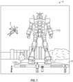
- FIG. 1 an augmented reality scene 4 is depicted wherein a user of an AR technology sees a real-world park-like setting 6 featuring people, trees, buildings in the background, and a concrete platform 1120.
- the user of the AR technology also perceives that he "sees" a robot statue 1110 standing upon the real-world platform 1120, and a cartoon-like avatar character 2 flying by which seems to be a personification of a bumble bee, even though these elements 2, 1110 do not exist in the real world.
- At least the elements 2, 1110 can be provided to the user at least in part by the portable (e.g., wearable) electronic devices disclosed herein.
- the human visual perception system is very complex, and producing a VR or AR technology that facilitates a comfortable, natural-feeling, rich presentation of virtual image elements amongst other virtual or real-world imagery elements is challenging.
- head-worn AR displays typically are at least loosely coupled to a user's head, and thus move when the user's head moves. If the user's head motions are detected by the display system, the data being displayed can be updated to take the change in head pose into account.
- a user wearing a head-worn display views a virtual representation of a three-dimensional (3D) object on the display and walks around the area where the 3D object appears, that 3D object can be re-rendered for each viewpoint, giving the user the perception that he or she is walking around an object that occupies real space.
- the head-worn display is used to present multiple objects within a virtual space (for instance, a rich virtual world)
- measurements of head pose e.g., the location and orientation of the user's head
- detection or calculation of head pose can facilitate the display system to render virtual objects such that they appear to occupy a space in the real world in a manner that makes sense to the user.
- detection of the position and/or orientation of a real object such as handheld device (which also may be referred to as a "totem"), haptic device, or other real physical object, in relation to the user's head or AR system may also facilitate the display system in presenting display information to the user to enable the user to interact with certain aspects of the AR system efficiently.
- the virtual objects may be re-rendered as a function of head pose, such that the virtual objects appear to remain stable relative to the real world.
- placement of virtual objects in spatial relation to physical objects may be a non-trivial problem.
- head movement may significantly complicate placement of virtual objects in a view of an ambient environment. Such is true whether the view is captured as an image of the ambient environment and then projected or displayed to the end user, or whether the end user perceives the view of the ambient environment directly. For instance, head movement will likely cause a field of view of the end user to change, which will likely require an update to where various virtual objects are displayed in the field of the view of the end user. Additionally, head movements may occur within a large variety of ranges and speeds.
- Head movement speed may vary not only between different head movements, but within or across the range of a single head movement. For instance, head movement speed may initially increase (e.g., linearly or not) from a starting point, and may decrease as an ending point is reached, obtaining a maximum speed somewhere between the starting and ending points of the head movement. Rapid head movements may even exceed the ability of the particular display or projection technology to render images that appear uniform and/or as smooth motion to the end user.
- Head tracking accuracy and latency have been challenges for VR and AR systems.
- the accuracy of head-tracking is high and that the overall system latency is very low from the first detection of head motion to the updating of the light that is delivered by the display to the user's visual system. If the latency is high, the system can create a mismatch between the user's vestibular and visual sensory systems, and generate a user perception scenario that can lead to motion sickness or simulator sickness. If the system latency is high, the apparent location of virtual objects will appear unstable during rapid head motions.
- head-worn display systems In addition to head-worn display systems, other display systems can benefit from accurate and low latency head pose detection. These include head-tracked display systems in which the display is not worn on the user's body, but is, e.g., mounted on a wall or other surface. The head-tracked display acts like a window onto a scene, and as a user moves his head relative to the "window" the scene is re-rendered to match the user's changing viewpoint. Other systems include a head-worn projection system, in which a head-worn display projects light onto the real world.
- AR systems may be designed to be interactive with the user. For example, multiple users may play a ball game with a virtual ball and/or other virtual objects. One user may "catch" the virtual ball, and throw the ball back to another user.
- a first user may be provided with a totem (e.g., a real bat communicatively coupled to the AR system) to hit the virtual ball.
- a virtual user interface may be presented to the AR user to allow the user to select one of many options. The user may use totems, haptic devices, wearable components, or simply touch the virtual screen to interact with the system.
- Detecting head pose and orientation of the user, and detecting a physical location of real objects in space enable the AR system to display virtual content in an effective and enjoyable manner.
- the AR system can recognize a physical location of a real object (e.g., user's head, totem, haptic device, wearable component, user's hand, etc.) and correlate the physical coordinates of the real object to virtual coordinates corresponding to one or more virtual objects being displayed to the user.
- This generally requires highly accurate sensors and sensor recognition systems that track a position and orientation of one or more objects at rapid rates.
- Current approaches do not perform localization at satisfactory speed or precision standards.
- FIG. 2A-2D some general componentry options are illustrated.
- various systems, subsystems, and components are presented for addressing the objectives of providing a high-quality, comfortably-perceived display system for human VR and/or AR.
- an AR system user 60 is depicted wearing head mounted component 58 featuring a frame 64 structure coupled to a display system 62 positioned in front of the eyes of the user.
- a speaker 66 is coupled to the frame 64 in the depicted configuration and positioned adjacent the ear canal of the user (in one embodiment, another speaker, not shown, is positioned adjacent the other ear canal of the user to provide for stereo / shapeable sound control).
- the display 62 is operatively coupled 68, such as by a wired lead or wireless connectivity, to a local processing and data module 70 which may be mounted in a variety of configurations, such as fixedly attached to the frame 64, fixedly attached to a helmet or hat 80 as shown in the embodiment of Figure 2B , embedded in headphones, removably attached to the torso 82 of the user 60 in a backpack-style configuration as shown in the embodiment of Figure 2C , or removably attached to the hip 84 of the user 60 in a belt-coupling style configuration as shown in the embodiment of Figure 2D .
- a local processing and data module 70 which may be mounted in a variety of configurations, such as fixedly attached to the frame 64, fixedly attached to a helmet or hat 80 as shown in the embodiment of Figure 2B , embedded in headphones, removably attached to the torso 82 of the user 60 in a backpack-style configuration as shown in the embodiment of Figure 2C , or removably attached to the hip 84 of
- the local processing and data module 70 may comprise a power-efficient processor or controller, as well as digital memory, such as flash memory, both of which may be utilized to assist in the processing, caching, and storage of data a) captured from sensors which may be operatively coupled to the frame 64, such as image capture devices (such as cameras), microphones, inertial measurement units, accelerometers, compasses, GPS units, radio devices, and/or gyros; and/or b) acquired and/or processed using the remote processing module 72 and/or remote data repository 74, possibly for passage to the display 62 after such processing or retrieval.
- image capture devices such as cameras
- microphones such as inertial measurement units
- accelerometers compasses
- GPS units GPS units
- radio devices radio devices
- the local processing and data module 70 may be operatively coupled 76, 78, such as via a wired or wireless communication links, to the remote processing module 72 and remote data repository 74 such that these remote modules 72, 74 are operatively coupled to each other and available as resources to the local processing and data module 70.
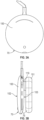
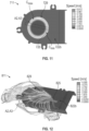
- Figure 3A is a schematic front plan view of the local processing and data module 70, according to one embodiment.
- Figure 3B is a schematic right side view of the local processing and data module 70 of Figure 3A .
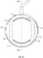
- the local processing and data module 70 can comprise a housing 75 comprising a first enclosure 100 and a second enclosure 101 mechanically connected with the first enclosure 100.
- the second enclosure 101 can be fluidly coupled with the first enclosure 100 in some embodiments.
- the first enclosure 100 and the second enclosure 101 are coupled to provide thermal isolation or separation therebetween, e.g., a gap (such as an air gap) between the enclosures 100, 101 can provide improved thermal isolation therebetween.
- the first enclosure 100 can comprise a front side 102 and a back side 103 opposite the front side 102.
- the second enclosure 101 can be coupled with the back side 103 of the first enclosure.
- a connection portion comprising a channel 119 can extend between the first and second enclosures 100, 101.
- the channel 119 of the connection portion can connect an internal chamber or cavity defined within the first enclosure 100 with an internal chamber or cavity defined within the second enclosures 101.
- the channel 119 can be sized to accommodate one or more electrical connectors extending between components within the first and second enclosures 100, 101.
- the channel 119 can provide heat transfer by fluid communication or other means between the first and second enclosures 100, 101, e.g., to improve heat dissipation within the housing 75.
- the local processing and data module 70 can comprise one or more inlet ports 104a, 104b configured to permit gas (e.g., air) to enter the housing 75, e.g., at a position on a periphery of the first enclosure 100.
- the local processing and data module 70 can also include one or more exhaust ports 105 to permit the gas (e.g., air) to exit the housing 75, e.g., at a position on a periphery of the first enclosure 100.
- air can flow into the enclosure 100 through the inlet ports 104a, 104b, and can exit the enclosure 100 through the exhaust port(s) 105.
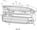
- Figure 3D is a schematic side cross-sectional view of the local processing and data module 70 shown in Figures 3A-3C .
- the local processing and data module 70 may include one or multiple electronic components 109 (illustrated schematically herein in block form), such as processors, memory dies, sensors, etc.
- the electronic components 109 can be disposed within a chamber or first compartment of the first enclosure 100 of the housing. As shown, the electronic components 109 can be arranged within a relatively low profile and a relatively small lateral footprint.
- the illustrated electronic components 109 are shown at or near the front side 102 of the first enclosure 100, but it should be appreciated that additional electronic components may be provided anywhere suitable in the enclosures 100, 101.
- a thermal mitigation assembly 110 can be provided in the housing (e.g., in the first enclosure 100) to remove heat generated by the electronic components 109 and to maintain the temperature of the housing at comfortable and/or effective levels during operation.
- the thermal mitigation assembly 110 is disposed rear of the electronic components 109.
- the thermal mitigation assembly 110 can comprise a first heat spreader 112 disposed on a first side of a fan assembly 111.
- the local processing and data module 70 may also include additional electronic components (e.g., an on-board power supply module 118) within the second enclosure 101 to provide power to the electronic components 109 in the first enclosure 100 such that the user need not be tethered to a wired power supply.
- the power supply 118 shown in Figure 3D can, for example, include one or a plurality of batteries.
- the on-board power supply may generate additional heat within the local processing and data module 70.
- the fan assembly 111 can draw a heat transfer medium (e.g., heated air or other heated gas) from the second enclosure 101 into the first enclosure 100, e.g., by way of the channel 119 that provides fluid communication between the enclosures 100, 101.
- a heat transfer medium e.g., heated air or other heated gas
- the heat sink 113 can comprise linked copper fin patterns, with each fin having a thickness in a range of 0.05 mm to 0.35 mm, e.g., in a range of 0.1 mm to 0.3 mm (about 0.2 mm in some embodiments).
- the fins can be spaced in a range of 0.25 mm to 2 mm, or in a range of 0.5 mm to 1.5 mm (about 1 mm in some embodiments).
- a second heat spreader 114 can be disposed on a second side of the fan assembly 111.
- the second heat spreader 114 can be disposed on a rear side of the fan assembly 111 and thus is sometimes a rear heat spreader.
- the first heat spreader 112 can be thermally and, optionally, mechanically coupled to some or all of the electronic components 109 by way of any suitable connector, such as a thermally conductive connector, a thermal gap pad, a thermal adhesive, etc.
- heat generated by the electronic components 109 may be conducted to the first heat spreader 112 by way of one or more thermal gap pads, which can comprise a thermally conductive elastomer.
- the thermal gap pads can generate pressure between the heat spreader 112 and the components so as to improve thermal conductivity.
- the heat can be conveyed from the heat spreader 112 and/or from the electronic components 109 along the thermal conveyance pathway 117 to the heat sink 113.
- the fan assembly 111 can drive or draw air over and/or around the first heat spreader 112, the thermal conveyance pathway 117, and/or the second heat spreader 114 to cool the first enclosure 100 and/or the second enclosure 101.
- influent air A1 can be drawn, by the fan assembly 111, into the first enclosure 100 by way of the inlet ports 104a, 104b.
- the fan assembly 111 can circulate cooling air A2 within the first enclosure 100 and over and/or around the electronic components 109 to cool the electronic components 109.
- the cooling air A2 may comprise ambient air drawn into the enclosure 100 without additional cooling in some embodiments.
- the fan assembly 111 can draw cooling air A3 into the first enclosure 100 from the second enclosure 101, e.g., by way of the channel 119.
- the electronic components 109 can be cooled by the cooling air A2 circulated within the enclosure 100.
- the battery or power supply 118 may also be cooled by way of the cooling air A3 drawn from the second enclosure 101 into the first enclosure 100. Heat from the second enclosure 101 can also be conducted by a thermal conductor into the first enclosure 100 in some embodiments and dissipated by the airflow described herein.
- the connection portion including the channel 119 can comprise a thermal insulating gap so as to mitigate or reduce the flow of heat from the first enclosure 100 to the second enclosure 101 (or vice versa).
- the cooling air currents A2 and A3 can be drawn or sucked into an airflow opening 129 formed in an interior portion (e.g., central portion) of the fan assembly 111.
- the cooling air A2 can pass laterally between the first heat spreader 112 or the base 115 and the fan assembly 111, and can enter the fan assembly 111 through the opening 129.
- the air drawn through the airflow opening 129 of the fan assembly 111 can be expelled radially outward through an outlet air opening 132 in an outflow air current A4 from the fan assembly 111.
- air pathways of the fan assembly 111 can extend between the airflow opening 129 disposed along the longitudinal axis L and the outlet airflow opening 132 having a face disposed about an axis non-parallel to the longitudinal axis L.
- the outlet airflow opening 132 can be disposed radially outward (e.g., generally perpendicular to the longitudinal axis L).
- the radially outflowing air current A4 can be directed over the heat sink 113 to drive thermal energy stored in the heat sink 113 out of the enclosure 100.
- expelled air A5 can be directed out of the first enclosure 100 through the exhaust port 105 to the outside environs.
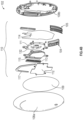
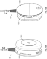
- Figure 4B is a schematic perspective, exploded view of the local processing and data module 70, according to another embodiment.
- the local processing and data module 70 of Figure 4B may be similar to the local processing and data module 70 of Figure 4A .
- in Figure 4B only a single inlet port 104 and a single exhaust port 105 are shown.
- any suitable number of inlet ports 104 and/or outlet ports 105 may be provided for intaking air into the enclosure 100 and for expelling air from the enclosure 100.
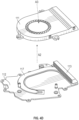
- Figure 4C is a schematic perspective, partially exploded view of the fan assembly 111 mounted to the first heat spreader 112.
- Figure 4D is a schematic, partially exploded view of the fan assembly 111, the heat spreader 112, the thermal conveyance pathway 117, and the heat sink 113.
- the electronic components 109 can be disposed near the front cover 108a.
- the first heat spreader 112 can be disposed rear of the electronic components, and the fan assembly 111 can be thermally coupled with, and disposed rear of, the first heat spreader 112.
- the first heat spreader 112 can be disposed between the electronic components 109 and the fan assembly 111.
- the fan assembly 111 can be thermally coupled with the first heat spreader 112.
- a gap may be disposed between the fan assembly 111 and the heat spreader 112 or base 115 to permit air to enter the opening 129.
- the base 115 and thermal conveyance pathway 117 are obscured in Figure 4C , since the base 115 and conveyance pathway 117 may be disposed between the heat spreader 112 and the fan assembly 111.
- the outflow air current A5 can pass over the heat sink 113 (obscured in Figure 4C ) disposed near (e.g., upstream of) the outlet opening 132 of the fan assembly 111.
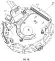
- the fan assembly 111 can comprise a rotational axis L and a transverse axis T disposed non-parallel relative to (e.g., perpendicular to) the axis L.
- the rotational axis L is a longitudinal axis of a shaft assembly or a shaft portion about which a portion of the fan assembly 111 rotates and thus is sometimes referred to as a longitudinal axis L.
- the cooling air currents A2 (see Figure 4D ) and A3 (see Figures 4C and 4D ) can enter the fan assembly 111 through the airflow opening 129 from heat source(s) in the housings 100, 101, e.g., from the electronic components 109 and the power supply 118, respectively.
- the air currents A2 can pass between the heat spreader 112 or the base 115 and the fan assembly 111, and can enter the opening 129.
- the cooling air currents A2, A3 can have velocity components aligned along the longitudinal axis L, at least locally in the vicinity of the opening 129 and at a corresponding opening on the opposite side of the fan assembly 111.
- the rotation of the blades of the fan assembly 111 can therefore draw air into the fan assembly 111 with high momentum along the longitudinal axis.
- the outflow air current A4 can be directed radially outward through the outlet opening 132, such that the air current A4 includes velocity components aligned along the transverse axis T.
- the outflow air current A4 can exit the enclosure 100 by way of the exhaust port 105 (see Figures 4A-4B ).
- Figure 4E illustrates a heat map of the assembled heat spreader, thermal conveyance pathway 117, and heat sink 113 during operation of the fan assembly 111.
- the heat map was computed using computational fluid dynamics (CFD) software.
- CFD computational fluid dynamics
- the thermal conveyance pathway 117 can be coupled with the heat spreader 112, e.g., disposed in a groove or channel of the heat spreader 112.
- the heat spreader 112 can comprise a thermally conductive material, such as copper.
- the thermal conveyance pathway 117 can comprise a heat pipe comprising a thermally conductive channel.
- a working fluid e.g., water
- the heat pipe of the conveyance pathway 117 can comprise a copper pipe that is flattened so as to have a cross-sectional profile that is generally elliptical.
- a major dimension of the heat pipe can be between two and ten times larger than a minor dimension of the heat pipe (e.g., between five and nine times larger).
- thermal energy Q can be stored in and/or conducted to the heat spreader 112 from the components 109.
- the thermal energy Q from the heat spreader 112 can be transferred to the heat sink 113 along one or more thermal pathways Q1, Q2.
- some thermal energy can be conveyed along a first pathway Q1 from the heat spreader 112 by way of the thermal conveyance pathway 117.
- a second pathway Q2 can convey thermal energy along the area of the heat spreader 112 to the heat sink.
- the conveyance pathway 117 can be significantly more thermally conductive than the first heat spreader 112 (e.g., at least five times, or at least ten times as thermally conductive as the heat spreader 112).
- heat can be rapidly transferred away from the heat sink by the outflow air current A4, as shown by the relatively cool temperatures maintained by the airflow over the heat sink 113.
- Maintaining the heat sink 113 at a cool temperature can increase the thermal gradient between the heat spreader 112 and/or the thermal conveyance pathway 117 and the heat sink 113.
- the disclosed embodiments can maintain the temperature of the local processing and data module 70 at suitably low temperatures.
- FIG. 5 is a schematic side cross-sectional view of a fan assembly 211 that can be used in conjunction with the local processing and data module 70 described herein.
- the fan assembly 211 can comprise a support frame 222 configured to provide structural support to the fan assembly 211.
- the frame 222 can comprise multiple frame portions connected together by, e.g., fasteners or other mechanical connectors. In other embodiments, the frame 222 can comprise a unitary body.
- a motor 220 can be mechanically coupled with the frame 222.
- a shaft assembly 223 can be connected to the motor 220 and can extend along the longitudinal axis L described above, such that the longitudinal axis extends between and/or through first and second ends of the shaft assembly 223.
- the shaft-supporting motor 220 may be considered part of the support frame 222 or frame assembly.
- the shaft assembly 223 is cantilevered relative to the motor 220 or the frame 222.
- the shaft assembly 223 can comprise a single shaft in some embodiments. In other embodiments, the shaft assembly 223 can comprise a plurality of shafts coupled together.
- a bearing 224 which can be a bushing, can be disposed at least partially around the shaft assembly 223.
- An impeller 221 can be operably coupled with and disposed about the bushing or other bearing 224.
- the motor 220 can comprise a stator (not shown) having one or more wire coils that, when energized by electric power, create changing or alternating magnetic fields sufficient to drive a magnetic rotor assembly (not shown) coupled or formed with the impeller 221 (e.g., in or on a hub or other central portion of the impeller 221).
- the magnetic fields generated by the motor 220 can interact with the magnetic rotor assembly of the impeller 221 to cause the magnetic rotor, and therefore the impeller 221) to rotate about the longitudinal axis L.
- the shaft assembly 223 can be fixed to the motor 220, or to the frame 222. Thus, in the illustrated embodiment, the shaft assembly 223 may not rotate.
- the bushing or other bearing 224 may be secured over or fixed to the shaft assembly 223, and the impeller 221 can rotate relative to the bushing 224 and the shaft assembly 223.
- the bushing or other bearing 224 may be secured or fixed to the impeller 221 and can rotate with the impeller 221 relative to the shaft assembly 223.
- the motor 220 can include internal stator and rotor assemblies that cause the shaft assembly 223 (or portion(s) thereof to rotate).
- the impeller 221 can be rotationally fixed relative to, and can rotate with, the shaft assembly 223.
- the impeller 221 can be driven to rotate at high speeds in order to adequately remove thermal energy from the housing.
- the impeller 221 can rotate at speeds between 5,000 rpm and 10,000 rpm, e.g., 8,000 rpm, or at higher speeds.
- the local processing and data module 70 can be worn or otherwise carried by the user for VR or AR experiences. The user may often be moving while wearing the module 70 and therefore, the local processing and data module 70, and the fan assembly 211 therein, may frequently be disposed at different angles relative to gravity g.
- the fan assembly 211 may be disposed at an angle, or may move at sufficiently high acceleration, such that the torque resulting from transverse loads on the shaft assembly 223 causes the shaft assembly 223 to bend or flex by an angle P as shown in Figure 5 .
- the deflection or bending of the shaft assembly 223 due to transverse loading conditions may cause the impeller 221 to contact or hit the interior surface of the frame 222, which can cause undesirable noise and/or vibration within the local processing and data module 70.
- the frequent application of such external torques to the shaft assembly 223 may cause the shaft assembly 223 to wear or experience fatigues, which may damage the shaft assembly.
- the shaft assembly 223 may be made sufficiently stiff so as to reduce the amount of deflection of the distal end of the shaft assembly 223.
- elements on the frame 222 can assist in preventing the impeller 221 and shaft assembly 223 from contacting the frame 222 or substantially deflecting.
- a frame portion 222' of the frame disposed about the impeller 221 can comprise one or more magnets in alignment with corresponding magnet(s) in the impeller 221.
- the magnets in the frame portion 222' and impeller can have like poles aligned so as to cause the impeller 221 to remain centered within the frame 222 or at least to oppose deflection of the impeller 221 toward the frame 222 on a transverse loading which may reduce or eliminate deflection of the shaft assembly 223.
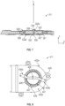
- Figure 6 is a rear plan view of a fan assembly 311, according to various embodiments disclosed herein.
- Figure 7 is a schematic side sectional view of the fan assembly 311 of Figure 6 .
- the components shown in Figures 6 and 7 may include components similar to like numbered components shown in Figure 5 .
- the fan assembly 311 can comprise a frame assembly that can have a first support frame 322a and a second support frame 322b coupled to the first frame 322a.
- the connected first and second support frames 322a, 322b can define an enclosure or chamber.
- the impeller 321 can be disposed between the first and second support frames 322a, 322b, e.g., within the enclosure defined by the frames 322a, 322b.
- the first and second support frames 322a, 322b can define a housing in which the impeller 321 is disposed.
- the impeller 321 of Figures 6 and 7 can comprise a hub 327 and one or a plurality of blades 328 (e.g., fan blades) coupled with and/or extending from the hub 327.
- the hub 327 can be coupled with the shaft assembly 323.
- a bushing can be disposed between the shaft assembly 323 and the hub 327.
- the impeller 321 can rotate relative to the rotationally fixed shaft assembly 323. In other embodiments, the impeller 321 can rotate with the rotating shaft assembly 323.
- a first end 333 of the shaft assembly 323 can be supported by or coupled with the first support frame 322a (e.g., to a support structure defined by or including the frame, to the motor, etc.)
- the first end 333 of the shaft assembly 123 can be secured to the first frame 322a at a first shaft support 330 of the first support frame 322a.
- the first end 333 can be welded, glued, or press fit onto the frame 322a.
- the first shaft support 330 can comprise a portion of a structural body defined by the first support frame 322a.
- the first support frame 322a can comprise the motor such that the first end 333 of the shaft assembly 323 is secured to the motor and the shaft support 330 comprises a portion of the motor. It should be appreciated that any suitable structure can be used as the shaft support 330 so as to secure the first end 333 of the shaft assembly 323.
- a second support frame 322b can be provided to control transverse loading on the shaft assembly 323.
- the second support frame 322b can be coupled with the first support frame 322a and can be disposed at or over a second end 334 of the shaft assembly 323 so as to control transverse loading at the second end 334 of the shaft assembly 323.
- the second support frame 322b can comprise a second shaft support 326 coupled with the second end 334 of the shaft assembly 323.
- the second shaft support 326 can be rigidly attached to the second support frame 322b across at least a portion of the airflow opening 329.
- the second shaft support 326 can comprise a pin or other connector that rigidly attaches the second end 334 of the shaft assembly 323 to the frame 322b.
- the second shaft support 326 e.g., a pin
- the second shaft support 326 can be connected concentrically or axially relative to the axis L about which the shaft assembly 323, the impeller 321 or both the shaft assembly 323 and the impeller rotate. Positioning the second shaft support 326 along or centered relative to the axis L can beneficially reduce deflections and improve the rotation of the impeller 321.
- the second shaft support 326 can comprise or be connected with an elongate member 325 between first and second end portions 335a, 335b thereof.
- the first end portion 335a of the elongate member 325 can be supported at a first portion of the second support frame 322b
- the second end portion 335b of the elongate member 325 can be supported at a second portion of the second support frame 322b.
- the first and second end portions 335a, 335b (and the corresponding first and second portions of the second frame 322b) can be spaced apart about a periphery of the airflow opening 329.
- first and second shaft portions 523a, 523b can comprise two separate shafts that are connected together, e.g., at the impeller 521.
- first and second shaft portions 523a, 523b can comprise a single shaft, with the first portion 523a on the first side of the impeller 521 and the second portion 523b on the second side of the impeller 521.
- the impeller 621 can be coupled with first and second shaft portions 623a, 623b of the shaft assembly 623.
- the first and second shaft portions 623a, 623b can comprise a single unitary shaft, or the first and second shaft portions 623a, 623b can comprise two separate shafts.
- the shaft portions 623a, 623b can be fixed to the impeller 621 so as to impart rotation to the impeller 621.
- a portion of the impeller hub 627 can include a follower magnet or rotor assembly.
- a stator assembly of the motor 620 can be energized so as to create magnetic forces on the hub 627 to impart rotation of the impeller 621.
- a concave member comprising a first bushing 624a can be coupled or formed with the first frame 622a and/or the motor 620.
- a second concave member comprising a second bushing 624b can be coupled or formed with the second frame 622b.
- the first bushing 624a can act as the first shaft support 630 to rotationally support the first end 633 of the shaft assembly 623
- the second bushing 624b can act as or comprise the second shaft support 626 to rotationally support the second end 634 of the shaft assembly 623.
- the first end 633 of the first shaft portion 623a can rotate within the first bushing 624a.
- the second end 634 of the second shaft portion 623a can rotate within the second bushing 624b.
- the second bushing 624b can assist in controlling the transverse loading on the shaft assembly 624 during operation of the fan assembly 611.
- the second bushing 624b of the shaft support 626 can be aligned along or aligned concentrically relative to the second shaft portion 623b.
- the second shaft support 626 can also comprise the elongate member 625 extending across part of or the entire airflow opening 629.
- one or both of the first and second bushings 624a, 624b can comprise a concave member, e.g., a concave inner surface.
- the concave inner surface may comprise or define a generally or substantially spherical surface.
- the concave inner surface defined in the first and/or second bushings 624a, 624b can beneficially permit rotation of the shaft assembly 623 while supporting both ends 633, 634 of the shaft assembly 623 against transverse loading conditions.
- the concave inner surfaces of the first and/or second bushings 624a, 624b can be shaped so as to accommodate small but acceptable rotation and/or translation of the ends 633, 634 of the shaft assembly 623. Accommodating such negligible movement of the ends 633, 634 can further reduce stresses on the shaft assembly 623 while preventing undesirable large deformations.
- Figures 10A-10D illustrate additional examples of a fan assembly that can be used in conjunction with the embodiments disclosed herein.
- Figure 10A is a schematic side view of a fan assembly 911 comprising a shaft assembly 923 that operably couples to an impeller assembly 921 by way of a bushing 924.
- the components shown in Figure 10A may include components similar to like numbered components shown in Figures 6-10 , with the reference numerals incremented by 100 relative to Figure 10 .
- the shaft assembly 923 can comprise a single shaft that can be connected at its ends to frames 922a, 922b (e.g., welded to the elongate member 925 or frame 922b, mechanically fastened, or otherwise fixed).
- one of the frames 922b can comprise the elongate member 925.
- the shaft assembly 923 can comprise a separate member from the bushing 924 and impeller 921, e.g., the shaft assembly 923 of Figure 10A may not be integrally formed with the bushing 924.
- the shaft assembly 923 may or may not be rotationally fixed to the bushing 924.
- the shaft assembly 923 may not be rotationally fixed to the bushing 924 such that the bushing 924 and impeller 921 may rotate relative to (e.g., may rotate about) the fixed shaft assembly 923.
- the bushing 924 and impeller 921 may be rotationally fixed or coupled to the shaft assembly 923 such that the impeller 921 and bushing 924 rotate with or follow the rotation of the shaft assembly 923.
- Figure 10B is a schematic side view of a fan assembly 1011 comprising a shaft assembly 1023 that operably couples to an impeller assembly 1021 by way of a bushing 1024.
- the components shown in Figure 10B may include components similar to like numbered components shown in Figures 6-10A , with the reference numerals incremented by 100 relative to Figure 10A .
- the shaft assembly 1023 may be physically integrated with the impeller 1021 (and/or with a bushing, not shown) so as to define a single unitary shaft assembly and impeller.
- the shaft assembly 1023 can be fixed at its ends to the frames 1022a, 1022b (one of which may comprise an elongate member 1025). Rotation of the shaft assembly 1023 can impart rotation to the integrally formed impeller 1021.
- Figure 10C is a schematic side view of a fan assembly 1111 comprising a shaft assembly 1123 having first and second shaft portions 1123a, 1123b operably coupled with the impeller 1121.
- the components shown in Figure 10C may include components similar to like numbered components shown in Figures 6-10B , with the reference numerals incremented by 100 relative to Figure 10B .
- the first and second shaft portions 1123a, 1123b can comprise separate shafts that are respectively coupled with the frames 1122a, 1122b.
- the first and second shaft portions 1123a, 1123b can connect to the impeller 1121 by way of the hub 1124.
- first and second shaft portions 1123a, 1123b can be fixed to the frames 1122a, 1122b such that the impeller 1121 and hub 1124 rotate relative to the shaft portions 1123a, 1123b.
- first and second shaft portions 1123a, 1123b can be fixed to the hub 1124 such that the hub 1124 and impeller 1121 can rotate with the first and second shaft portions 1123a, 1123b.
- Figure 10D is a schematic side view of a fan assembly 1211 comprising a shaft assembly 1223 having first and second shaft portions 1223a, 1223b operably coupled with the impeller 1221.
- the components shown in Figure 10D may include components similar to like numbered components shown in Figures 6-10C , with the reference numerals incremented by 100 relative to Figure 10C .
- the first shaft portion 1223a can be integrally formed with the first frame 1222a, e.g., the first shaft portion 1223a and the first frame 1222a can define a single unitary component such that the first shaft portion 1223a extends from the first frame 1222a.
- the second shaft portion 1223b can be integrally formed with the second frame 1222b, e.g., the second shaft portion 1223b and the second frame 1222b can define a single unitary component such that the second shaft portion 1223b extends from the second frame 1222b.
- the first and second shaft portions 1223a, 1223b can be fixed such that the hub 1224 and impeller 1221 rotate relative to the shaft portions 1223a, 1223b.
- Figure 11 is a plan view of flow patterns within a fan assembly 711 before an elongate member 725 is attached to the fan assembly 711.
- Figure 12 is a schematic perspective view of flow patterns within and around a fan assembly 811 after the elongate member 825 is placed at a desired orientation relative to the fan assembly 811.
- the flow patterns of Figures 11 and 12 were computed using computational fluid dynamics (CFD) techniques.
- CFD computational fluid dynamics
- Figure 11 represents the velocity field of cooling air currents A2, A3 (see Figure 4A ) that flow into the airflow opening 729 of the fan assembly 711, without or before the elongate member 725 is attached.
- the fan assembly 711 may be used in conjunction with various types of portable electronic devices, which may include different types or numbers of electronic components.
- the flow patterns through the fan assembly 711 can be computed to determine the velocity field of the fan assembly 711 during operation and accounting for the electronic components within the housing.
- the circumferential location Cmax representative of maximum or increased airflow can be determined.
- the circumferential location Cmin representative of minimum or reduced airflow can be determined.
- the desired orientation of the elongate member 725 can be selected. In some cases, it may be desirable to orient the elongate member 725 to correspond to minimum airflow through the opening 729.
- one end portion of the elongate member 725 can be positioned at the circumferential location Cmin and the other end portion can be disposed at an opposite circumferential location.
- the first and second end portions of the elongate member 725 can be positioned circumferentially based on a weighted average or other determinative criteria for minimum airflow. By positioning the elongate member 725 at regions of minimum or reduced airflow, the effect of the elongate member 725 on the airflow into the fan assembly 711 can be reduced or eliminated.
- Figure 12 illustrates the airflow pathways A2, A3 and their velocity profiles through the fan assembly 811 after the elongate member 825 is oriented according to the selections and determinations made in connection with Figure 11 .
- the elongate member 825 does not appreciably reduce the airflow through the fan assembly 811. Rather, the airflow pathways A2, A3 pass over the elongate member 825 with little or no loss of momentum.
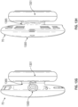
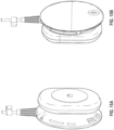
- Figure 13A is a schematic back, left perspective view of an electronic device according to one embodiment.
- Figure 13B is a schematic front, right perspective view of the electronic device of Figure 13A .
- Figure 13C is a schematic front plan view of the electronic device of Figures 13A-13B .
- Figure 13D is a schematic back plan view of the electronic device of Figures 13A-13C .
- Figure 13E is a schematic right side view of the electronic device of Figures 13A-13D .
- Figure 13F is a schematic left side view of the electronic device of Figures 13A-13E .
- Figure 13G is a schematic top plan view of the electronic device of Figures 13A-13F .
- Figure 13H is a schematic bottom plan view of the electronic device of Figures 13A-13G .
- the electronic device can comprise the local processing and data module 70 described above.
- the local processing and data module 70 can comprise a first enclosure 1300 (which may be similar to the enclosure 100) and a second enclosure 1301 spaced from the first enclosure 1300 by a gap 1367.
- one or more electronic devices e.g., processor(s)
- processor(s) may be provided in a first compartment defined at least in part by the first enclosure 1301.
- One or more other electronic devices e.g., one or more batteries, one or more processor(s), etc.
- the electronic device can be desirable to operate at high speeds (e.g., at high speeds for central processing and/or graphics processing units), while also charging the power supply (e.g., battery(ies) of the electronic device).
- the battery(ies) disclosed herein can be any suitable type of battery, including, e.g., a lithium ion battery(ies).
- the processor(s) can operate up to about 95 °C before throttling back (e.g., before dynamic frequency scaling or throttling is started).
- Such high temperatures for processor operation may exceed the maximum temperature thresholds for effective battery usage (e.g., which may be at or near 45 °C in some embodiments).
- the temperature rise from operating the processor(s) at high speeds may reduce the ability to rapidly and effectively charge the battery(ies) during use of the electronic device (e.g., during high speed operation of the processor(s)).
- the processor and battery operating temperatures are schematic, and that the processor(s) and battery(ies) can be operated at various temperatures.
- various embodiments disclosed herein utilize the first and second enclosures 1300, 1301 in conjunction with a connection portion 1365 to thermally separate the compartments of the enclosures 1300, 1301.
- the processor(s) may be disposed in the first compartment of the first enclosure 1300, and may operate at high speeds and, therefore, high temperatures.
- the battery(ies) can be disposed in the second compartment of the second enclosure 1301 and can electrically communicate with other components of the device, e.g., with the processor(s) in the first enclosure 1300.
- one or more processing elements can be disposed in the first enclosure 1300, and one or more other processing elements can be disposed in the second enclosure 1301.
- the processing elements in both enclosures 1300, 1301 can be used to control the operation of the system.
- connection portion 1365 can comprise the channel 1319, which may be similar to the channel 119 described above.
- connection portion 1365 can comprise an air or thermal gap that separates the first and second enclosures 1300, 1301.
- the relatively low thermal conductivity of the air gap (and high thermal insulation properties) can serve to thermally separate the processor(s) in the first enclosure 1300 from the battery(ies) in the second enclosure 1301.
- one or more connectors or wires can pass through the channel 119 to electrically connect the processor(s) in the first enclosure 1300 with the battery(ies) of the second enclosure 1301. Additional components may also be provided in the first and/or second enclosures 1300, 1301.
- the thermal gap provided by the connection portion 1365 can reduce or substantially prevent heat from passing from the processor(s) in the first enclosure 1300 to the battery(ies) in the second enclosure 1301.
- the processor(s) can operate at relatively high speeds and temperatures, while maintaining the battery(ies) at sufficiently low temperatures so as to enable charging during operation of the processor(s).
- providing the battery(ies) and processor(s) within a single compartment or enclosure may not provide adequate heat separation between the battery(ies) and processor(s).
- connection portion 1365 comprises an air gap to provide thermal insulation between the first and second enclosures 1300, 1301.
- other low thermal conductivity materials such as insulators or dielectrics
- a thermally insulating polymer e.g., potting compound or encapsulant
- the first and second compartments defined by the first and second enclosures 1300, 1301 may also be filled with a gas (e.g., air).
- the electronic devices e.g., processor(s), battery(ies), etc.
- another type of insulating material such as a polymer or dielectric.
- the first and second enclosures 1300, 1301 can be separated by a gap 1367 (e.g., at a location spaced from or below the connection portion 1365) having a gap width G as shown in Figure 13E , which may be similar or generally the same as the width or gap defined by the connection portion 1365 disposed or extending between the first and second enclosures 1300, 1301.
- the gap 1367 e.g., an air gap between the enclosures 1300, 1301) can provide improved thermal separation between the first and second enclosures 1300, 1301.
- a majority of the spaces between the compartments within first and second enclosures 1300, 1301 may be filled with air or a gas.
- the channel 1319 can be filled with a gas in some embodiments, and the gap 1367 between outer portions of the enclosures 1300, 1301 can comprise a gas such as air.
- the channel 1319 can have a side cross-sectional area that is smaller than a cross-sectional area of the first compartment of the first enclosure 1300 (and/or smaller than the cross-sectional area of the second compartment of the second enclosure 1301), taken along a direction parallel to a maximum dimension of the first compartment.
- the enclosures 1300, 1301 can comprise a clip 1366 disposed within the gap 1367.
- the clip 1366 can comprise projection(s) extending from the first and second enclosures 1300, 1301.
- the clip 1366 can improve wearability of the module 70, e.g., on a belt or other clothing accessory of the user).
- the gap width G of the connection portion 1365 (e.g., the channel 1319) and/or the gap 1367 may be in a range of 0.5 mm to 10 mm, in a range of 1 mm to 7 mm, or in a range of 1 mm to 5 mm.
- Providing a thermal gap or thermal barrier may provide sufficient thermal separation between the enclosures 1300, 1301.
- one or both of the enclosures 1300, 1301 may be constructed of a material that has a relatively low thermal conductivity so as to further improve the thermal barrier between the internal compartments of the enclosures 1300, 1301.
- a lower thermal conductivity material e.g., aluminum or plastic
- the thermal gap provided by the connection portion 1365 and/or the gap 1367 may still permit at least some heat flow from the first enclosure 1300 to the second enclosure 1301. The fan assemblies disclosed herein can mitigate this heat transfer, however, so as to reduce heat dissipation from the first enclosure 1300 to the second enclosure 1301.
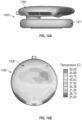
- Figure 14A is a schematic heat transfer map 1450 of a side view of the electronic device of Figures 13A-13H during operation of the electronic devices.
- Figure 14B is a schematic top view of the heat transfer map 1450.
- the temperature profile of the first enclosure 1300 in which the processor(s) may be disposed
- the second enclosure 1301 in which the battery(ies) may be disposed
- connection portion 1365 and/or the gap 1367 provide adequate thermal separation between the enclosures 1300, 1301.
- Various embodiments can beneficially provide thermal separation between the enclosures 1300, 1301 of at least 40 °C, at least 50 °C, etc.
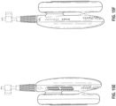
- Figure 15A is a schematic back, left perspective view of an electronic device according to one embodiment of the present design.
- Figure 15B is a schematic front, right perspective view of the electronic device of Figure 15A .
- Figure 15C is a schematic front plan view of the electronic device of Figures 15A-15B .
- Figure 15D is a schematic back plan view of the electronic device of Figures 15A-15C .
- Figure 15E is a schematic right side view of the electronic device of Figures 15A-15D .
- Figure 15F is a schematic left side view of the electronic device of Figures 15A-15E .
- Figure 15G is a schematic top plan view of the electronic device of Figures 15A-15F .
- Figure 15H is a schematic bottom plan view of the electronic device of Figures 15A-15G .
- Various embodiments are accordingly directed to the ornamental designs for an electronic device, as shown and described herein, including at least in Figures 15A-15H .
- Embodiment 1 An electronic device comprising:
- Embodiment 2 The electronic device of Embodiment 1, wherein the first electronic component comprises a processor.
- Embodiment 3 The electronic device of any one of Embodiments 1 to 2, wherein the second electronic component comprises a power supply.
- Embodiment 4 The electronic device of Embodiment 3, wherein the power supply comprises a battery.
- Embodiment 5 The electronic device of any one of Embodiments 1 to 4, wherein the first compartment, the second compartment, and the connection portion are filled with a gas.
- Embodiment 6 The electronic device of any one of Embodiments 1 to 5, wherein the connection portion comprises a channel between the first and second compartments.
- Embodiment 7 The electronic device of Embodiment 6, wherein the channel has a side cross-sectional area that is smaller than a cross-sectional area of the first compartment taken along a direction parallel to a maximum dimension of the first compartment.
- Embodiment 8 The electronic device of any one of Embodiments 1 to 7, wherein the electronic device comprises an augmented reality device.
- Embodiment 9 The electronic device of Embodiment 8, further comprising a connector configured to connect to a headpiece to be worn by a user.
- Embodiment 10 The electronic device of any one of Embodiments 1 to 9, wherein the first electronic component electrically communicates with the second electronic component.
- Embodiment 11 The electronic device of any one of Embodiments 1 to 10, further comprising a clip disposed in the gap between the first and second compartments.
- Embodiment 12 A portable electronic device comprising:
- Embodiment 13 The power supply assembly of Embodiment 12, wherein the housing comprises a first enclosure and a second enclosure, the electronic components and the thermal mitigation assembly disposed in the first enclosure and the battery disposed in the second enclosure.
- Embodiment 14 The power supply assembly of Embodiment 12 or 13, wherein the shaft assembly comprises a first shaft portion connected to a first frame of the frame assembly and a second shaft portion connected to a second frame of the frame assembly, the first and second shaft portions disposed at least partially on opposing sides of the hub.
- Embodiment 15 A fan assembly, comprising:
- Embodiment 16 The fan assembly of Embodiment 15, wherein the second support frame comprises an airflow opening disposed about the longitudinal axis which extends between the first and second ends of the shaft assembly.
- Embodiment 17 The fan assembly of Embodiment 16, further comprising a shaft support coupled with the second end of the shaft assembly, the shaft support being rigidly attached to the second support frame across the airflow opening.
- Embodiment 18 The fan assembly of Embodiment 17, wherein the shaft support is supported at respective first and second portions of the second support frame, the respective first and second portions spaced apart about a periphery of the airflow opening.
- Embodiment 19 The fan assembly of Embodiment 18, wherein the first portion of the second support frame is generally on an opposite side of the airflow opening relative to the second portion of the second support frame.
- Embodiment 20 The fan assembly of any one of Embodiments 17 to 19, wherein the shaft support is disposed in a rotational position of the airflow opening corresponding to a maximum of air flow when the impeller is operating.
- Embodiment 21 The fan assembly of any one of Embodiments 17 to 20, wherein the shaft support comprises an elongate member between first and second ends thereof, the elongate member having an airfoil shape.
- Embodiment 22 The fan assembly of any one of Embodiments 17 to 21, wherein the shaft support comprises an elongate member between the first and second ends thereof, the elongate member having varying width along the length thereof.
- Embodiment 23 The fan assembly of any one of Embodiments 17 to 22, wherein the shaft support comprises an elongate member between the first and second ends thereof, the elongate member having varying thickness along the length thereof.
- Embodiment 24 The fan assembly of any one of Embodiments 15 to 23, wherein the shaft assembly comprises a first shaft portion rotationally fixed to the first support frame and a second portion rotationally fixed to the impeller, the second portion being rotatable over a free end of the first shaft portion of the shaft assembly.
- Embodiment 25 The fan assembly of any one of Embodiments 15 to 24, wherein the shaft assembly comprises an elongate member having a first end disposed on a first side of the impeller and a second end disposed on a second side of the impeller, the second side being opposite the first side.
- Embodiment 26 The fan assembly of Embodiment 25, further comprising a concave member coupled with the second support frame and configured to rotationally support the second end of the elongate member.
- Embodiment 27 The fan assembly of Embodiment 26, further comprising an additional concave member coupled with the first support frame and configured to rotationally support the first end of the elongate member.
- Embodiment 28 The fan assembly of any one of Embodiments 16 to 27, wherein an airflow pathway of the fan assembly extends between the airflow opening disposed about the longitudinal axis and a second airflow opening having a face disposed about an axis non-parallel to the longitudinal axis.
- Embodiment 29 The fan assembly of Embodiment 28, wherein the axis non-parallel to the longitudinal axis is disposed generally perpendicular to the longitudinal axis and along a radial-extending axis of the impeller.
- Embodiment 30 A fan assembly, comprising:
- Embodiment 31 A fan assembly comprising:
- Embodiment 32 The fan assembly of Embodiment 31, wherein the angle relative to the non-parallel axis is acute.
- Embodiment 33 The fan assembly of Embodiment 32, wherein the angle relative to the non-parallel axis is in a range of -45° to 45°.
- Embodiment 34 The fan assembly of Embodiment 33, wherein the angle relative to the non-parallel axis is in a range of -30° to 30°.
- Embodiment 35 A method of manufacturing a fan assembly, the method comprising:
- Embodiment 36 The method of Embodiment 35, further comprising, based on the computing, angularly positioning the elongate member at least partially across the first airflow opening at an angle relative to the non-parallel axis that permits at least a local maximum of airflow through the first airflow opening.
- Embodiment 37 The method of Embodiment 36, wherein angularly positioning comprises orienting the angle relative to the non-parallel axis at an acute angle.
- Embodiment 38 The method of Embodiment 37, wherein angularly positioning comprises orienting the angle relative to the non-parallel axis in a range of -45° to 45°.
- Embodiment 39 The method of Embodiment 38, wherein angularly positioning comprises orienting the angle relative to the non-parallel axis in a range of -30° to 30°.
- Any processes, methods, and algorithms described herein and/or depicted in the attached figures may be embodied in, and fully or partially automated by, code modules executed by one or more physical computing systems, hardware computer processors, application-specific circuitry, and/or electronic hardware configured to execute specific and particular computer instructions.
- computing systems can include general purpose computers (e.g., servers) programmed with specific computer instructions or special purpose computers, special purpose circuitry, and so forth.
- a code module may be compiled and linked into an executable program, installed in a dynamic link library, or may be written in an interpreted programming language.
- particular operations and methods may be performed by circuitry that is specific to a given function.
- a video may include many frames, with each frame having millions of pixels, and specifically programmed computer hardware is necessary to process the video data to provide a desired image processing task or application in a commercially reasonable amount of time.
- Code modules or any type of data may be stored on any type of non-transitory computer-readable medium, such as physical computer storage including hard drives, solid state memory, random access memory (RAM), read only memory (ROM), optical disc, volatile or non-volatile storage, combinations of the same and/or the like.
- the methods and modules (or data) may also be transmitted as generated data signals (e.g., as part of a carrier wave or other analog or digital propagated signal) on a variety of computer-readable transmission mediums, including wireless-based and wired/cable-based mediums, and may take a variety of forms (e.g., as part of a single or multiplexed analog signal, or as multiple discrete digital packets or frames).
- the results of the disclosed processes or process steps may be stored, persistently or otherwise, in any type of non-transitory, tangible computer storage or may be communicated via a computer-readable transmission medium.
- any processes, blocks, states, steps, or functionalities in flow diagrams described herein and/or depicted in the attached figures should be understood as potentially representing code modules, segments, or portions of code which include one or more executable instructions for implementing specific functions (e.g., logical or arithmetical) or steps in the process.
- the various processes, blocks, states, steps, or functionalities can be combined, rearranged, added to, deleted from, modified, or otherwise changed from the illustrative examples provided herein.
- additional or different computing systems or code modules may perform some or all of the functionalities described herein.
- the processes, methods, and systems may be implemented in a network (or distributed) computing environment.
- Network environments include enterprise-wide computer networks, intranets, local area networks (LAN), wide area networks (WAN), personal area networks (PAN), cloud computing networks, crowd-sourced computing networks, the Internet, and the World Wide Web.
- the network may be a wired or a wireless network or any other type of communication network.
- the invention includes methods that may be performed using the subject devices.
- the methods may comprise the act of providing such a suitable device. Such provision may be performed by the end user.
- the "providing" act merely requires the end user obtain, access, approach, position, set-up, activate, power-up or otherwise act to provide the requisite device in the subject method.
- Methods recited herein may be carried out in any order of the recited events which is logically possible, as well as in the recited order of events.
- a phrase referring to "at least one of' a list of items refers to any combination of those items, including single members.
- "at least one of: A, B, or C” is intended to cover: A, B, C, A and B, A and C, B and C, and A, B, and C.
- Conjunctive language such as the phrase "at least one of X, Y and Z," unless specifically stated otherwise, is otherwise understood with the context as used in general to convey that an item, term, etc. may be at least one of X, Y or Z. Thus, such conjunctive language is not generally intended to imply that certain embodiments require at least one of X, at least one of Y and at least one of Z to each be present.
Landscapes
- Engineering & Computer Science (AREA)
- Theoretical Computer Science (AREA)
- General Engineering & Computer Science (AREA)
- Physics & Mathematics (AREA)
- General Physics & Mathematics (AREA)
- Computer Hardware Design (AREA)
- Human Computer Interaction (AREA)
- Mechanical Engineering (AREA)
- Microelectronics & Electronic Packaging (AREA)
- Power Engineering (AREA)
- Thermal Sciences (AREA)
- Optics & Photonics (AREA)
- Computer Graphics (AREA)
- Software Systems (AREA)
- General Chemical & Material Sciences (AREA)
- Electrochemistry (AREA)
- Chemical Kinetics & Catalysis (AREA)
- Chemical & Material Sciences (AREA)
- Manufacturing & Machinery (AREA)
- Biophysics (AREA)
- Life Sciences & Earth Sciences (AREA)
- Cooling Or The Like Of Electrical Apparatus (AREA)
- Structures Of Non-Positive Displacement Pumps (AREA)
- Motor Or Generator Cooling System (AREA)
- Secondary Cells (AREA)
Applications Claiming Priority (4)
| Application Number | Priority Date | Filing Date | Title |
|---|---|---|---|
| US201762512635P | 2017-05-30 | 2017-05-30 | |
| US201862671379P | 2018-05-14 | 2018-05-14 | |
| PCT/US2018/034948 WO2018222618A1 (en) | 2017-05-30 | 2018-05-29 | Power supply assembly with fan assembly for electronic device |
| EP18810860.9A EP3631874B1 (de) | 2017-05-30 | 2018-05-29 | Stromversorgungsanordnung mit lüfteranordnung für elektronische vorrichtung |
Related Parent Applications (1)
| Application Number | Title | Priority Date | Filing Date |
|---|---|---|---|
| EP18810860.9A Division EP3631874B1 (de) | 2017-05-30 | 2018-05-29 | Stromversorgungsanordnung mit lüfteranordnung für elektronische vorrichtung |
Publications (2)
| Publication Number | Publication Date |
|---|---|
| EP4513253A2 true EP4513253A2 (de) | 2025-02-26 |
| EP4513253A3 EP4513253A3 (de) | 2025-04-30 |
Family
ID=64455804
Family Applications (2)
| Application Number | Title | Priority Date | Filing Date |
|---|---|---|---|
| EP18810860.9A Active EP3631874B1 (de) | 2017-05-30 | 2018-05-29 | Stromversorgungsanordnung mit lüfteranordnung für elektronische vorrichtung |
| EP25150308.2A Pending EP4513253A3 (de) | 2017-05-30 | 2018-05-29 | Stromversorgungsanordnung mit lüfteranordnung für elektronische vorrichtung |
Family Applications Before (1)
| Application Number | Title | Priority Date | Filing Date |
|---|---|---|---|
| EP18810860.9A Active EP3631874B1 (de) | 2017-05-30 | 2018-05-29 | Stromversorgungsanordnung mit lüfteranordnung für elektronische vorrichtung |
Country Status (9)
| Country | Link |
|---|---|
| US (4) | US10871806B2 (de) |
| EP (2) | EP3631874B1 (de) |
| JP (3) | JP7319927B2 (de) |
| KR (3) | KR20240069815A (de) |
| CN (2) | CN116666814A (de) |
| AU (2) | AU2018277530B2 (de) |
| CA (1) | CA3059984C (de) |
| IL (3) | IL303933B2 (de) |
| WO (1) | WO2018222618A1 (de) |
Families Citing this family (22)
| Publication number | Priority date | Publication date | Assignee | Title |
|---|---|---|---|---|
| JP6863896B2 (ja) | 2014-09-29 | 2021-04-21 | マジック リープ,インコーポレイティド | 導波路から異なる波長の光を出力する構造および方法 |
| KR102641964B1 (ko) | 2016-05-12 | 2024-02-27 | 매직 립, 인코포레이티드 | 이미징 도파관을 통해 분배된 광 조작 |
| AU2017361096B2 (en) | 2016-11-16 | 2022-09-01 | Magic Leap, Inc. | Thermal management systems for wearable components |
| IL303933B2 (en) | 2017-05-30 | 2024-08-01 | Magic Leap Inc | Power supply assembly with fan assembly for an electronic device |
| US11138915B2 (en) | 2017-07-28 | 2021-10-05 | Magic Leap, Inc. | Fan assembly for displaying an image |
| WO2020023491A1 (en) | 2018-07-24 | 2020-01-30 | Magic Leap, Inc. | Thermal management system for electronic device |
| EP4648573A3 (de) * | 2018-12-13 | 2026-01-14 | Hewlett-Packard Development Company, L.P. | Rechnervorrichtungen mit integrierter und isolierter flüssigkeitskühlung |
| US10859326B2 (en) * | 2019-01-09 | 2020-12-08 | Dell Products L.P. | Fin stack for processor cooling |
| EP3976726B1 (de) | 2019-05-28 | 2025-09-10 | Magic Leap, Inc. | Wärmeverwaltungssystem für tragbare elektronische vorrichtungen |
| TWI695669B (zh) * | 2019-06-21 | 2020-06-01 | 仁寶電腦工業股份有限公司 | 散熱模組 |
| CN110716315A (zh) * | 2019-11-29 | 2020-01-21 | 北京枭龙防务科技有限公司 | 一种智能眼镜 |
| USD961915S1 (en) | 2020-02-05 | 2022-08-30 | Magic Leap, Inc. | Holder with device |
| USD986245S1 (en) | 2020-02-05 | 2023-05-16 | Magic Leap, Inc. | Holster with retractable device |
| USD933358S1 (en) | 2020-02-05 | 2021-10-19 | Magic Leap, Inc. | Belt with device holders |
| USD998324S1 (en) | 2020-02-05 | 2023-09-12 | Magic Leap, Inc. | Belt assembly with holders and devices |
| USD975716S1 (en) | 2020-02-05 | 2023-01-17 | Magic Leap, Inc. | Holder for controller |
| USD961914S1 (en) | 2020-02-05 | 2022-08-30 | Magic Leap, Inc. | Holster for retractable device |
| US11512711B2 (en) * | 2020-09-18 | 2022-11-29 | Asia Vital Components Co., Ltd. | Centrifugal fan frame body structure |
| EP4603951A3 (de) * | 2021-06-09 | 2025-09-24 | Snap Inc. | Vorrichtung mit dynamischer transcodedrosselung |
| US11483569B1 (en) * | 2021-06-09 | 2022-10-25 | Snap Inc. | Device with dynamic transcode throttling |
| WO2024058459A1 (ko) * | 2022-09-13 | 2024-03-21 | 삼성전자주식회사 | 복수의 발열원들에 대한 방열을 위한 전자 장치 및 방법 |
| CN219754832U (zh) * | 2023-03-14 | 2023-09-26 | 台达电子工业股份有限公司 | 离心式风扇模块 |
Family Cites Families (159)
| Publication number | Priority date | Publication date | Assignee | Title |
|---|---|---|---|---|
| US1921218A (en) * | 1932-02-29 | 1933-08-08 | Clyde W Colby | Fan |
| US2853539A (en) | 1952-10-14 | 1958-09-23 | Ultra Electric Inc | Enclosure for electronic apparatus |
| US4385911A (en) * | 1982-01-22 | 1983-05-31 | Ronco Teleproducts, Inc. | Air filtering device |
| US5082422A (en) | 1991-06-10 | 1992-01-21 | Wang Sui Mu | Illuminative fan |
| US5291560A (en) | 1991-07-15 | 1994-03-01 | Iri Scan Incorporated | Biometric personal identification system based on iris analysis |
| US6222525B1 (en) | 1992-03-05 | 2001-04-24 | Brad A. Armstrong | Image controllers with sheet connected sensors |
| US5610678A (en) * | 1993-12-30 | 1997-03-11 | Canon Kabushiki Kaisha | Camera including camera body and independent optical viewfinder |
| US5577888A (en) * | 1995-06-23 | 1996-11-26 | Siemens Electric Limited | High efficiency, low-noise, axial fan assembly |
| US5670988A (en) | 1995-09-05 | 1997-09-23 | Interlink Electronics, Inc. | Trigger operated electronic device |
| JP3348576B2 (ja) | 1995-11-10 | 2002-11-20 | ソニー株式会社 | 温度検出装置、これを搭載した半導体素子およびこれを用いたオートフォーカスシステム |
| JPH09230321A (ja) | 1996-02-20 | 1997-09-05 | Denso Corp | カラー液晶表示装置 |
| US5993060A (en) | 1997-01-14 | 1999-11-30 | Citizen Watch Co., Ltd. | Temperature sensor and method of adjusting the same |
| US6037876A (en) | 1998-04-23 | 2000-03-14 | Limelite Industries, Inc. | Lighted message fan |
| US6594630B1 (en) | 1999-11-19 | 2003-07-15 | Voice Signal Technologies, Inc. | Voice-activated control for electrical device |
| US6349864B1 (en) * | 1999-12-23 | 2002-02-26 | Hsin-Kuo Lee | Mechanical arrangement for promoting portable computer's adaptability to application |
| JP3070325U (ja) * | 2000-01-17 | 2000-07-28 | 元山科技工業股▲分▼有限公司 | 軸流ファンの軸の支持構造 |
| JP2001308999A (ja) * | 2000-04-20 | 2001-11-02 | Kenwood Corp | 携帯電話無線機 |
| US6567269B2 (en) * | 2001-04-23 | 2003-05-20 | Hewlett-Packard Development Company, L.P. | Computer system having removable processor and modular thermal unit |
| JP4375920B2 (ja) * | 2001-05-17 | 2009-12-02 | ティーオーエー株式会社 | ファン制御装置及びファン制御方法 |
| US6561762B1 (en) * | 2001-11-14 | 2003-05-13 | Sunonwealth Electric Machine Industry Co., Ltd. | Housing structure of a fan |
| JP2003216071A (ja) | 2002-01-21 | 2003-07-30 | Noritsu Koki Co Ltd | 回転型表示装置 |
| JP2003244296A (ja) | 2002-02-20 | 2003-08-29 | Seiko Epson Corp | 携帯電話機及びパソコン |
| US6805536B2 (en) * | 2003-01-28 | 2004-10-19 | Averatec Inc. | Heat dissipation fan |
| US8118674B2 (en) | 2003-03-27 | 2012-02-21 | Wms Gaming Inc. | Gaming machine having a 3D display |
| US20040223299A1 (en) | 2003-05-07 | 2004-11-11 | Prosenjit Ghosh | Display cooling |
| TWM240488U (en) * | 2003-07-02 | 2004-08-11 | Datech Technology Co Ltd | Fan with guiding rib in vent |
| US7157818B2 (en) * | 2003-11-17 | 2007-01-02 | Emerson Electric Co. | Low noise ventilation system for electric motor |
| TW200517815A (en) | 2003-11-28 | 2005-06-01 | Soltek Comp Inc | Heat sink device of computer case |
| JP2005252732A (ja) * | 2004-03-04 | 2005-09-15 | Olympus Corp | 撮像装置 |
| US7484716B2 (en) * | 2004-04-14 | 2009-02-03 | University Of Southern California | Scent delivery device and method of simulating scent in a virtual environment |
| JP2005308980A (ja) | 2004-04-20 | 2005-11-04 | Seiko Epson Corp | 回転型表示装置 |
| US20070247832A1 (en) | 2004-04-23 | 2007-10-25 | Barker Dale E | Fan with Bladers and Method for Displaying Illuminated Pictoral Elements |
| USD514570S1 (en) | 2004-06-24 | 2006-02-07 | Microsoft Corporation | Region of a fingerprint scanning device with an illuminated ring |
| US8411108B2 (en) | 2004-07-21 | 2013-04-02 | Lightning Wheels, Llc | Rotational display system |
| US7142423B2 (en) * | 2004-10-26 | 2006-11-28 | Comarco Wireless Technologies, Inc. | Power adapter with fan assembly |
| US20060109200A1 (en) | 2004-11-22 | 2006-05-25 | Alden Ray M | Rotating cylinder multi-program and auto-stereoscopic 3D display and camera |
| US7250954B2 (en) | 2004-12-16 | 2007-07-31 | Palo Alto Research Center, Incorporated | Three-dimensional image rendering devices and methods |
| US20070081123A1 (en) | 2005-10-07 | 2007-04-12 | Lewis Scott W | Digital eyewear |
| US8696113B2 (en) | 2005-10-07 | 2014-04-15 | Percept Technologies Inc. | Enhanced optical and perceptual digital eyewear |
| US11428937B2 (en) | 2005-10-07 | 2022-08-30 | Percept Technologies | Enhanced optical and perceptual digital eyewear |
| WO2007048206A1 (en) * | 2005-10-28 | 2007-05-03 | Resmed Ltd | Single or multiple stage blower and nested volute(s) and/or impeller(s) therefor |
| US20070109787A1 (en) | 2005-11-14 | 2007-05-17 | Chin-Ping Wu | Light emitting heat sink fan |
| US7390166B2 (en) * | 2005-11-15 | 2008-06-24 | Zippy Technology Corp. | Rotary structure for radiation fans |
| JP5128772B2 (ja) * | 2006-01-18 | 2013-01-23 | Necカシオモバイルコミュニケーションズ株式会社 | 折畳み式電子機器 |
| JP2007226013A (ja) | 2006-02-24 | 2007-09-06 | Orient Corp | 立体画像表示装置 |
| US20100247344A1 (en) * | 2006-12-18 | 2010-09-30 | Sheng-An Yang | Heat dissipating fan |
| JP5087981B2 (ja) * | 2007-04-23 | 2012-12-05 | 富士通株式会社 | 電子機器 |
| JP5009679B2 (ja) * | 2007-05-15 | 2012-08-22 | 株式会社リコー | 情報処理装置 |
| JP2009071516A (ja) * | 2007-09-12 | 2009-04-02 | Olympus Imaging Corp | 電子カメラ |
| US20090155055A1 (en) * | 2007-12-18 | 2009-06-18 | Hon Hai Precision Industry Co., Ltd. | Cooling fan |
| WO2009128839A1 (en) | 2008-04-19 | 2009-10-22 | Hewlett-Packard Development Company, L.P. | Device and method for cooling fan control using measured amperage load |
| JP5361878B2 (ja) * | 2008-05-15 | 2013-12-04 | パナソニック株式会社 | ファン及びそれを備えた電子機器 |
| CN101586575A (zh) | 2008-05-23 | 2009-11-25 | 富准精密工业(深圳)有限公司 | 离心风扇及使用该离心风扇的电子装置 |
| TWI349072B (en) * | 2008-07-04 | 2011-09-21 | Inventec Corp | Wind guiding cover |
| US20100074747A1 (en) * | 2008-09-22 | 2010-03-25 | Chien-Chun Yu | Mini axial fan with an improved core shaft structure |
| TWM351277U (en) * | 2008-09-25 | 2009-02-21 | Risun Expanse Corp | Positioning structure of fan |
| US8011878B2 (en) * | 2008-12-07 | 2011-09-06 | Furui Precise Component (Kunshan) Co., Ltd. | Centrifugal fan and electronic device using same |
| TWM382382U (en) * | 2009-06-05 | 2010-06-11 | Delta Electronics Inc | An and its stator module and water-repellent structure |
| TWM371180U (en) * | 2009-06-26 | 2009-12-21 | Micro Star Int Co Ltd | Position-limiting structure of fan |
| US20110157322A1 (en) | 2009-12-31 | 2011-06-30 | Broadcom Corporation | Controlling a pixel array to support an adaptable light manipulator |
| CN201656433U (zh) | 2010-02-05 | 2010-11-24 | 国基电子(上海)有限公司 | 过热保护电路及使用其的电子设备 |
| WO2011097564A1 (en) * | 2010-02-05 | 2011-08-11 | Kopin Corporation | Touch sensor for controlling eyewear |
| TWM391269U (en) * | 2010-03-16 | 2010-10-21 | Wistron Corp | Heat dissipating structure,heat dissipating module and electronic device capable of preventing airflow from flowing back |
| US20110263200A1 (en) * | 2010-04-26 | 2011-10-27 | Sony Ericsson Mobile Communications Ab | Vibrating motor disposed external to electronic device |
| US8400765B2 (en) * | 2010-09-20 | 2013-03-19 | Amazon Technologies, Inc. | System with air flow under data storage devices |
| US9304319B2 (en) | 2010-11-18 | 2016-04-05 | Microsoft Technology Licensing, Llc | Automatic focus improvement for augmented reality displays |
| AU2011348122A1 (en) | 2010-12-24 | 2013-07-11 | Magic Leap Inc. | An ergonomic head mounted display device and optical system |
| US10156722B2 (en) | 2010-12-24 | 2018-12-18 | Magic Leap, Inc. | Methods and systems for displaying stereoscopy with a freeform optical system with addressable focus for virtual and augmented reality |
| US8712598B2 (en) | 2011-01-14 | 2014-04-29 | Microsoft Corporation | Adaptive flow for thermal cooling of devices |
| JP2012168446A (ja) | 2011-02-16 | 2012-09-06 | Nikon Corp | 外部装置 |
| US20120224951A1 (en) * | 2011-03-04 | 2012-09-06 | Apple Inc. | Compact fan assembly with thrust bearing |
| WO2012154620A2 (en) | 2011-05-06 | 2012-11-15 | Magic Leap, Inc. | Massive simultaneous remote digital presence world |
| CN102878094A (zh) * | 2011-07-14 | 2013-01-16 | 鸿富锦精密工业(深圳)有限公司 | 风扇组合 |
| US8963956B2 (en) * | 2011-08-19 | 2015-02-24 | Microsoft Technology Licensing, Llc | Location based skins for mixed reality displays |
| JP2013064996A (ja) | 2011-08-26 | 2013-04-11 | Nikon Corp | 三次元画像表示装置 |
| US9323325B2 (en) * | 2011-08-30 | 2016-04-26 | Microsoft Technology Licensing, Llc | Enhancing an object of interest in a see-through, mixed reality display device |
| CN202372910U (zh) * | 2011-09-28 | 2012-08-08 | 深圳市顶星数码网络技术有限公司 | 一种散热装置 |
| WO2013049861A1 (en) | 2011-09-29 | 2013-04-04 | Magic Leap, Inc. | Tactile glove for human-computer interaction |
| EP3258671B1 (de) | 2011-10-28 | 2018-09-05 | Magic Leap, Inc. | System und verfahren für eine erweiterte virtuelle realität |
| CA2858208C (en) | 2011-11-23 | 2019-01-15 | Magic Leap, Inc. | Three dimensional virtual and augmented reality display system |
| JP6095686B2 (ja) | 2011-12-06 | 2017-03-15 | オステンド・テクノロジーズ・インコーポレーテッド | 空間光学型及び時空間光学型指向性光変調器 |
| CA3111134A1 (en) | 2012-04-05 | 2013-10-10 | Magic Leap, Inc. | Wide-field of view (fov) imaging devices with active foveation capability |
| US10054964B2 (en) * | 2012-05-07 | 2018-08-21 | Google Llc | Building control unit method and controls |
| JP2013251721A (ja) * | 2012-05-31 | 2013-12-12 | Toshiba Corp | テレビジョン受像機および電子機器 |
| BE1019941A3 (nl) | 2012-06-05 | 2013-02-05 | Tait Technologies Bvba | Inrichting voor de weergave van driedimensionale beelden, systeem voor de creatie van driedimensionale beelden, en werkwijze voor de creatie van driedimensionale beelden. |
| CN107817556B (zh) | 2012-06-11 | 2020-01-31 | 奇跃公司 | 使用波导反射器阵列投射器的多深度平面三维显示器 |
| US9671566B2 (en) | 2012-06-11 | 2017-06-06 | Magic Leap, Inc. | Planar waveguide apparatus with diffraction element(s) and system employing same |
| US9390643B2 (en) | 2012-06-25 | 2016-07-12 | Rufus Butler Seder | Rotatable animation devices with staggered illumination sources |
| US9841537B2 (en) | 2012-07-02 | 2017-12-12 | Nvidia Corporation | Near-eye microlens array displays |
| US9572552B1 (en) * | 2012-08-09 | 2017-02-21 | Integrated Medical Systems International, Inc. | Battery pack for power surgical hand piece with heat dissipating means |
| JP2015534108A (ja) | 2012-09-11 | 2015-11-26 | マジック リープ, インコーポレイテッド | 人間工学的な頭部搭載型ディスプレイデバイスおよび光学システム |
| JP2014071499A (ja) * | 2012-09-27 | 2014-04-21 | Kyocera Corp | 表示装置および制御方法 |
| US20140143934A1 (en) * | 2012-11-27 | 2014-05-29 | Peter Grzybowski | Transportable air circulating and cooling assembly for use with a head covering |
| US9448407B2 (en) * | 2012-12-13 | 2016-09-20 | Seiko Epson Corporation | Head-mounted display device, control method for head-mounted display device, and work supporting system |
| US9398357B2 (en) | 2012-12-22 | 2016-07-19 | Homewerks Worldwide, LLC | Audio equipped fan |
| US10151875B2 (en) | 2013-01-15 | 2018-12-11 | Magic Leap, Inc. | Ultra-high resolution scanning fiber display |
| GB201304220D0 (en) * | 2013-03-08 | 2013-04-24 | Tomtom Int Bv | Fitness watch case |
| CN105188516B (zh) | 2013-03-11 | 2017-12-22 | 奇跃公司 | 用于增强和虚拟现实的系统与方法 |
| CN107577350B (zh) | 2013-03-15 | 2020-10-23 | 奇跃公司 | 显示系统和方法 |
| JP6280771B2 (ja) * | 2013-03-27 | 2018-02-14 | ミネベアミツミ株式会社 | 送風機、モータおよびその製造方法 |
| CN103336532B (zh) | 2013-04-26 | 2016-06-15 | 杨毅 | 3d视听觉系统的支持装置及3d视听觉系统 |
| US10262462B2 (en) | 2014-04-18 | 2019-04-16 | Magic Leap, Inc. | Systems and methods for augmented and virtual reality |
| US9874749B2 (en) | 2013-11-27 | 2018-01-23 | Magic Leap, Inc. | Virtual and augmented reality systems and methods |
| US9880325B2 (en) | 2013-08-14 | 2018-01-30 | Nvidia Corporation | Hybrid optics for near-eye displays |
| KR102058523B1 (ko) * | 2013-10-10 | 2020-01-22 | 인텔 코포레이션 | 소형 폼팩터 디바이스에서의 구조적 강도 증가, 사이즈 감소, 안전성 개선, 열성능 향상 및 충전 가속화를 위한 재료의 사용 |
| KR102462848B1 (ko) | 2013-10-16 | 2022-11-03 | 매직 립, 인코포레이티드 | 조절가능한 동공간 거리를 가지는 가상 또는 증강 현실 헤드셋들 |
| US9352062B2 (en) * | 2013-10-30 | 2016-05-31 | S.C. Johnson & Son, Inc. | Wearable chemical dispenser |
| US9639125B2 (en) * | 2013-10-31 | 2017-05-02 | Microsoft Technology Licensing, Llc | Centrifugal fan with integrated thermal transfer unit |
| US9857591B2 (en) | 2014-05-30 | 2018-01-02 | Magic Leap, Inc. | Methods and system for creating focal planes in virtual and augmented reality |
| CN107219628B (zh) | 2013-11-27 | 2020-05-01 | 奇跃公司 | 虚拟和增强现实系统与方法 |
| CN106461955B (zh) | 2014-01-31 | 2019-08-13 | 奇跃公司 | 显示增强现实的方法 |
| AU2015210704B2 (en) | 2014-01-31 | 2019-05-30 | Magic Leap, Inc. | Multi-focal display system and method |
| US20150238141A1 (en) * | 2014-02-26 | 2015-08-27 | Hing Yin Lai | Watch with separate processor and display housing |
| US10203762B2 (en) | 2014-03-11 | 2019-02-12 | Magic Leap, Inc. | Methods and systems for creating virtual and augmented reality |
| GB201405107D0 (en) | 2014-03-21 | 2014-05-07 | Old Bond London Ltd | Display apparatus |
| AU2015297036B2 (en) | 2014-05-09 | 2017-09-28 | Google Llc | Systems and methods for discerning eye signals and continuous biometric identification |
| USD759657S1 (en) | 2014-05-19 | 2016-06-21 | Microsoft Corporation | Connector with illumination region |
| US9913401B2 (en) * | 2014-05-29 | 2018-03-06 | Arris Enterprises Llc | Pivotable fan assembly and associated systems |
| CN106662754B (zh) | 2014-05-30 | 2021-05-25 | 奇跃公司 | 用于采用虚拟或增强现实装置生成虚拟内容显示的方法和系统 |
| USD752529S1 (en) | 2014-06-09 | 2016-03-29 | Comcast Cable Communications, Llc | Electronic housing with illuminated region |
| US20150379770A1 (en) | 2014-06-27 | 2015-12-31 | David C. Haley, JR. | Digital action in response to object interaction |
| EP3007029B1 (de) * | 2014-10-07 | 2017-12-27 | LG Electronics Inc. | Mobiles endgerät und wearable-vorrichtung |
| US10048722B2 (en) * | 2014-10-15 | 2018-08-14 | AzTrong Inc. | Wearable portable electronic device with heat conducting path |
| ES2667195T3 (es) * | 2014-11-04 | 2018-05-10 | Abb Schweiz Ag | Dispositivo eléctrico |
| US9684172B2 (en) | 2014-12-03 | 2017-06-20 | Osterhout Group, Inc. | Head worn computer display systems |
| CN104566757A (zh) * | 2014-12-26 | 2015-04-29 | 必宜(天津)科技有限公司 | 一种窗台板式通风净化装置 |
| KR102439993B1 (ko) * | 2015-02-27 | 2022-09-06 | 삼성전자주식회사 | 방열 장치를 구비한 전자 장치 및 이의 제어 방법 |
| NZ773847A (en) | 2015-03-16 | 2022-07-01 | Magic Leap Inc | Methods and systems for diagnosing and treating health ailments |
| US9926935B2 (en) * | 2015-04-10 | 2018-03-27 | Arris Enterprises Llc | Fan assembly and associated systems |
| WO2016170717A1 (ja) * | 2015-04-23 | 2016-10-27 | ソニー株式会社 | ウェアラブルディスプレイ、情報処理システム及び制御方法 |
| USD758367S1 (en) | 2015-05-14 | 2016-06-07 | Magic Leap, Inc. | Virtual reality headset |
| CN106358419B (zh) * | 2015-07-16 | 2019-05-10 | 中兴通讯股份有限公司 | 模块化数据中心 |
| CN204945946U (zh) | 2015-09-23 | 2016-01-06 | 河北建材职业技术学院 | 电脑屏幕控制系统 |
| US10034411B2 (en) * | 2015-09-25 | 2018-07-24 | Apple Inc. | Thermal flow assembly including integrated fan |
| US10046234B2 (en) * | 2015-10-20 | 2018-08-14 | OBE Gaming Inc. | Interactive movement tracking system applicable to articles of clothing |
| CN114063311B (zh) | 2016-01-29 | 2024-11-26 | 奇跃公司 | 三维图像的显示 |
| KR20160030149A (ko) * | 2016-02-26 | 2016-03-16 | 김정훈 | 팬모터 구조를 갖는 초박형의 휴대단말용 냉각장치 |
| CN109315025A (zh) * | 2016-03-01 | 2019-02-05 | 美亚知识产权有限公司 | 感应燃烧器冷却系统及方法 |
| USD805734S1 (en) | 2016-03-04 | 2017-12-26 | Nike, Inc. | Shirt |
| USD794288S1 (en) | 2016-03-11 | 2017-08-15 | Nike, Inc. | Shoe with illuminable sole light sequence |
| US9848515B1 (en) * | 2016-05-27 | 2017-12-19 | Advanced Micro Devices, Inc. | Multi-compartment computing device with shared cooling device |
| US10989221B2 (en) * | 2016-06-29 | 2021-04-27 | Quanta Computer Inc. | Cooling system for streamlined airflow |
| WO2018027241A1 (en) | 2016-08-05 | 2018-02-08 | Passport Food Safety Solutions, Inc. | High volume low pressure feeder system |
| USD797749S1 (en) * | 2016-08-22 | 2017-09-19 | Magic Leap, Inc. | Mobile computing support system |
| IL307594B2 (en) | 2016-08-22 | 2025-08-01 | Magic Leap Inc | Virtual, augmented, and mixed reality systems and methods |
| AU2017361096B2 (en) | 2016-11-16 | 2022-09-01 | Magic Leap, Inc. | Thermal management systems for wearable components |
| JP2018124721A (ja) * | 2017-01-31 | 2018-08-09 | セイコーエプソン株式会社 | 頭部装着型表示装置、及び頭部装着型表示装置の制御方法 |
| US10534412B2 (en) | 2017-02-16 | 2020-01-14 | Astronics Advanced Electronic Systems Corp. | Control of temperature in a USB type C source through re-negotiation of power delivery object |
| JP6885102B2 (ja) * | 2017-02-24 | 2021-06-09 | コニカミノルタ株式会社 | 情報処理機器 |
| US10037062B1 (en) | 2017-03-17 | 2018-07-31 | Microsoft Technology Licensing, Llc | Thermal venting device with pressurized plenum |
| US20180285923A1 (en) * | 2017-03-31 | 2018-10-04 | Eye Labs, LLC | Scent marketing and advertising campaigns for digital content |
| IL303933B2 (en) | 2017-05-30 | 2024-08-01 | Magic Leap Inc | Power supply assembly with fan assembly for an electronic device |
| US20180348828A1 (en) | 2017-06-05 | 2018-12-06 | Motorola Mobility Llc | Systems, Methods, and Modular Attachment Devices for Thermal Management of an Electronic Device |
| US11138915B2 (en) | 2017-07-28 | 2021-10-05 | Magic Leap, Inc. | Fan assembly for displaying an image |
| CN207609586U (zh) | 2017-12-08 | 2018-07-13 | 东莞市擎宇电子科技有限公司 | 一种全息幻影成像风扇 |
| WO2020023491A1 (en) | 2018-07-24 | 2020-01-30 | Magic Leap, Inc. | Thermal management system for electronic device |
| CN209638039U (zh) * | 2019-01-08 | 2019-11-15 | 深圳吾迪科技有限公司 | 一种具备音乐功能的制冷颈圈 |
| WO2020138917A1 (en) * | 2018-12-24 | 2020-07-02 | Samsung Electronics Co., Ltd. | Cooler with wireless charging function for mobile electronic device |
| EP3976726B1 (de) | 2019-05-28 | 2025-09-10 | Magic Leap, Inc. | Wärmeverwaltungssystem für tragbare elektronische vorrichtungen |
-
2018
- 2018-05-29 IL IL303933A patent/IL303933B2/en unknown
- 2018-05-29 US US15/992,032 patent/US10871806B2/en active Active
- 2018-05-29 WO PCT/US2018/034948 patent/WO2018222618A1/en not_active Ceased
- 2018-05-29 JP JP2019555851A patent/JP7319927B2/ja active Active
- 2018-05-29 IL IL311011A patent/IL311011A/en unknown
- 2018-05-29 IL IL270856A patent/IL270856B2/en unknown
- 2018-05-29 EP EP18810860.9A patent/EP3631874B1/de active Active
- 2018-05-29 EP EP25150308.2A patent/EP4513253A3/de active Pending
- 2018-05-29 CN CN202310648397.4A patent/CN116666814A/zh active Pending
- 2018-05-29 KR KR1020247014561A patent/KR20240069815A/ko active Pending
- 2018-05-29 KR KR1020247001914A patent/KR102664361B1/ko active Active
- 2018-05-29 KR KR1020197034143A patent/KR102627882B1/ko active Active
- 2018-05-29 AU AU2018277530A patent/AU2018277530B2/en active Active
- 2018-05-29 CA CA3059984A patent/CA3059984C/en active Active
- 2018-05-29 CN CN201880036283.1A patent/CN110710014B/zh active Active
-
2020
- 2020-12-18 US US17/127,826 patent/US11797065B2/en active Active
-
2022
- 2022-09-26 JP JP2022152410A patent/JP7480236B2/ja active Active
-
2023
- 2023-09-06 US US18/243,048 patent/US12085999B2/en active Active
-
2024
- 2024-01-31 JP JP2024012745A patent/JP2024036439A/ja not_active Withdrawn
- 2024-03-20 AU AU2024201816A patent/AU2024201816B2/en active Active
- 2024-08-01 US US18/792,470 patent/US20240393844A1/en active Pending
Also Published As
Similar Documents
| Publication | Publication Date | Title |
|---|---|---|
| AU2024201816B2 (en) | Power supply assembly with fan assembly for electronic device | |
| US20240402773A1 (en) | Thermal management system for electronic device | |
| JP7357081B2 (ja) | ポータブル電子デバイスのための熱管理システム | |
| JPWO2018222618A5 (de) |
Legal Events
| Date | Code | Title | Description |
|---|---|---|---|
| PUAI | Public reference made under article 153(3) epc to a published international application that has entered the european phase |
Free format text: ORIGINAL CODE: 0009012 |
|
| STAA | Information on the status of an ep patent application or granted ep patent |
Free format text: STATUS: THE APPLICATION HAS BEEN PUBLISHED |
|
| AC | Divisional application: reference to earlier application |
Ref document number: 3631874 Country of ref document: EP Kind code of ref document: P |
|
| AK | Designated contracting states |
Kind code of ref document: A2 Designated state(s): AL AT BE BG CH CY CZ DE DK EE ES FI FR GB GR HR HU IE IS IT LI LT LU LV MC MK MT NL NO PL PT RO RS SE SI SK SM TR |
|
| REG | Reference to a national code |
Ref country code: DE Ref legal event code: R079 Free format text: PREVIOUS MAIN CLASS: G02B0027010000 Ipc: H01K0005020000 |
|
| PUAL | Search report despatched |
Free format text: ORIGINAL CODE: 0009013 |
|
| AK | Designated contracting states |
Kind code of ref document: A3 Designated state(s): AL AT BE BG CH CY CZ DE DK EE ES FI FR GB GR HR HU IE IS IT LI LT LU LV MC MK MT NL NO PL PT RO RS SE SI SK SM TR |
|
| RIC1 | Information provided on ipc code assigned before grant |
Ipc: F04D 29/056 20060101ALI20250321BHEP Ipc: G02B 27/00 20060101ALI20250321BHEP Ipc: G06F 1/20 20060101ALI20250321BHEP Ipc: F04D 25/06 20060101ALI20250321BHEP Ipc: H05K 7/20 20060101ALI20250321BHEP Ipc: H01K 5/02 20060101AFI20250321BHEP |
|
| STAA | Information on the status of an ep patent application or granted ep patent |
Free format text: STATUS: REQUEST FOR EXAMINATION WAS MADE |
|
| 17P | Request for examination filed |
Effective date: 20251030 |