EP4484584A1 - Hot-dip galvanized steel material - Google Patents
Hot-dip galvanized steel material Download PDFInfo
- Publication number
- EP4484584A1 EP4484584A1 EP24194567.4A EP24194567A EP4484584A1 EP 4484584 A1 EP4484584 A1 EP 4484584A1 EP 24194567 A EP24194567 A EP 24194567A EP 4484584 A1 EP4484584 A1 EP 4484584A1
- Authority
- EP
- European Patent Office
- Prior art keywords
- phase
- hot
- less
- plating layer
- dip
- Prior art date
- Legal status (The legal status is an assumption and is not a legal conclusion. Google has not performed a legal analysis and makes no representation as to the accuracy of the status listed.)
- Pending
Links
Images
Classifications
-
- B—PERFORMING OPERATIONS; TRANSPORTING
- B32—LAYERED PRODUCTS
- B32B—LAYERED PRODUCTS, i.e. PRODUCTS BUILT-UP OF STRATA OF FLAT OR NON-FLAT, e.g. CELLULAR OR HONEYCOMB, FORM
- B32B15/00—Layered products comprising a layer of metal
- B32B15/01—Layered products comprising a layer of metal all layers being exclusively metallic
- B32B15/013—Layered products comprising a layer of metal all layers being exclusively metallic one layer being formed of an iron alloy or steel, another layer being formed of a metal other than iron or aluminium
-
- B—PERFORMING OPERATIONS; TRANSPORTING
- B32—LAYERED PRODUCTS
- B32B—LAYERED PRODUCTS, i.e. PRODUCTS BUILT-UP OF STRATA OF FLAT OR NON-FLAT, e.g. CELLULAR OR HONEYCOMB, FORM
- B32B15/00—Layered products comprising a layer of metal
- B32B15/01—Layered products comprising a layer of metal all layers being exclusively metallic
- B32B15/016—Layered products comprising a layer of metal all layers being exclusively metallic all layers being formed of aluminium or aluminium alloys
-
- B—PERFORMING OPERATIONS; TRANSPORTING
- B32—LAYERED PRODUCTS
- B32B—LAYERED PRODUCTS, i.e. PRODUCTS BUILT-UP OF STRATA OF FLAT OR NON-FLAT, e.g. CELLULAR OR HONEYCOMB, FORM
- B32B15/00—Layered products comprising a layer of metal
- B32B15/04—Layered products comprising a layer of metal comprising metal as the main or only constituent of a layer, which is next to another layer of the same or of a different material
- B32B15/043—Layered products comprising a layer of metal comprising metal as the main or only constituent of a layer, which is next to another layer of the same or of a different material of metal
-
- B—PERFORMING OPERATIONS; TRANSPORTING
- B32—LAYERED PRODUCTS
- B32B—LAYERED PRODUCTS, i.e. PRODUCTS BUILT-UP OF STRATA OF FLAT OR NON-FLAT, e.g. CELLULAR OR HONEYCOMB, FORM
- B32B15/00—Layered products comprising a layer of metal
- B32B15/18—Layered products comprising a layer of metal comprising iron or steel
-
- C—CHEMISTRY; METALLURGY
- C21—METALLURGY OF IRON
- C21D—MODIFYING THE PHYSICAL STRUCTURE OF FERROUS METALS; GENERAL DEVICES FOR HEAT TREATMENT OF FERROUS OR NON-FERROUS METALS OR ALLOYS; MAKING METAL MALLEABLE, e.g. BY DECARBURISATION OR TEMPERING
- C21D1/00—General methods or devices for heat treatment, e.g. annealing, hardening, quenching or tempering
- C21D1/26—Methods of annealing
-
- C—CHEMISTRY; METALLURGY
- C21—METALLURGY OF IRON
- C21D—MODIFYING THE PHYSICAL STRUCTURE OF FERROUS METALS; GENERAL DEVICES FOR HEAT TREATMENT OF FERROUS OR NON-FERROUS METALS OR ALLOYS; MAKING METAL MALLEABLE, e.g. BY DECARBURISATION OR TEMPERING
- C21D8/00—Modifying the physical properties by deformation combined with, or followed by, heat treatment
- C21D8/02—Modifying the physical properties by deformation combined with, or followed by, heat treatment during manufacturing of plates or strips
- C21D8/0278—Modifying the physical properties by deformation combined with, or followed by, heat treatment during manufacturing of plates or strips involving a particular surface treatment
-
- C—CHEMISTRY; METALLURGY
- C21—METALLURGY OF IRON
- C21D—MODIFYING THE PHYSICAL STRUCTURE OF FERROUS METALS; GENERAL DEVICES FOR HEAT TREATMENT OF FERROUS OR NON-FERROUS METALS OR ALLOYS; MAKING METAL MALLEABLE, e.g. BY DECARBURISATION OR TEMPERING
- C21D9/00—Heat treatment, e.g. annealing, hardening, quenching or tempering, adapted for particular articles; Furnaces therefor
- C21D9/46—Heat treatment, e.g. annealing, hardening, quenching or tempering, adapted for particular articles; Furnaces therefor for sheet metals
-
- C—CHEMISTRY; METALLURGY
- C22—METALLURGY; FERROUS OR NON-FERROUS ALLOYS; TREATMENT OF ALLOYS OR NON-FERROUS METALS
- C22C—ALLOYS
- C22C18/00—Alloys based on zinc
-
- C—CHEMISTRY; METALLURGY
- C22—METALLURGY; FERROUS OR NON-FERROUS ALLOYS; TREATMENT OF ALLOYS OR NON-FERROUS METALS
- C22C—ALLOYS
- C22C18/00—Alloys based on zinc
- C22C18/04—Alloys based on zinc with aluminium as the next major constituent
-
- C—CHEMISTRY; METALLURGY
- C23—COATING METALLIC MATERIAL; COATING MATERIAL WITH METALLIC MATERIAL; CHEMICAL SURFACE TREATMENT; DIFFUSION TREATMENT OF METALLIC MATERIAL; COATING BY VACUUM EVAPORATION, BY SPUTTERING, BY ION IMPLANTATION OR BY CHEMICAL VAPOUR DEPOSITION, IN GENERAL; INHIBITING CORROSION OF METALLIC MATERIAL OR INCRUSTATION IN GENERAL
- C23C—COATING METALLIC MATERIAL; COATING MATERIAL WITH METALLIC MATERIAL; SURFACE TREATMENT OF METALLIC MATERIAL BY DIFFUSION INTO THE SURFACE, BY CHEMICAL CONVERSION OR SUBSTITUTION; COATING BY VACUUM EVAPORATION, BY SPUTTERING, BY ION IMPLANTATION OR BY CHEMICAL VAPOUR DEPOSITION, IN GENERAL
- C23C2/00—Hot-dipping or immersion processes for applying the coating material in the molten state without affecting the shape; Apparatus therefor
- C23C2/04—Hot-dipping or immersion processes for applying the coating material in the molten state without affecting the shape; Apparatus therefor characterised by the coating material
- C23C2/06—Zinc or cadmium or alloys based thereon
-
- C—CHEMISTRY; METALLURGY
- C23—COATING METALLIC MATERIAL; COATING MATERIAL WITH METALLIC MATERIAL; CHEMICAL SURFACE TREATMENT; DIFFUSION TREATMENT OF METALLIC MATERIAL; COATING BY VACUUM EVAPORATION, BY SPUTTERING, BY ION IMPLANTATION OR BY CHEMICAL VAPOUR DEPOSITION, IN GENERAL; INHIBITING CORROSION OF METALLIC MATERIAL OR INCRUSTATION IN GENERAL
- C23C—COATING METALLIC MATERIAL; COATING MATERIAL WITH METALLIC MATERIAL; SURFACE TREATMENT OF METALLIC MATERIAL BY DIFFUSION INTO THE SURFACE, BY CHEMICAL CONVERSION OR SUBSTITUTION; COATING BY VACUUM EVAPORATION, BY SPUTTERING, BY ION IMPLANTATION OR BY CHEMICAL VAPOUR DEPOSITION, IN GENERAL
- C23C2/00—Hot-dipping or immersion processes for applying the coating material in the molten state without affecting the shape; Apparatus therefor
- C23C2/26—After-treatment
- C23C2/28—Thermal after-treatment, e.g. treatment in oil bath
- C23C2/29—Cooling or quenching
-
- C—CHEMISTRY; METALLURGY
- C23—COATING METALLIC MATERIAL; COATING MATERIAL WITH METALLIC MATERIAL; CHEMICAL SURFACE TREATMENT; DIFFUSION TREATMENT OF METALLIC MATERIAL; COATING BY VACUUM EVAPORATION, BY SPUTTERING, BY ION IMPLANTATION OR BY CHEMICAL VAPOUR DEPOSITION, IN GENERAL; INHIBITING CORROSION OF METALLIC MATERIAL OR INCRUSTATION IN GENERAL
- C23C—COATING METALLIC MATERIAL; COATING MATERIAL WITH METALLIC MATERIAL; SURFACE TREATMENT OF METALLIC MATERIAL BY DIFFUSION INTO THE SURFACE, BY CHEMICAL CONVERSION OR SUBSTITUTION; COATING BY VACUUM EVAPORATION, BY SPUTTERING, BY ION IMPLANTATION OR BY CHEMICAL VAPOUR DEPOSITION, IN GENERAL
- C23C2/00—Hot-dipping or immersion processes for applying the coating material in the molten state without affecting the shape; Apparatus therefor
- C23C2/50—Controlling or regulating the coating processes
-
- C—CHEMISTRY; METALLURGY
- C23—COATING METALLIC MATERIAL; COATING MATERIAL WITH METALLIC MATERIAL; CHEMICAL SURFACE TREATMENT; DIFFUSION TREATMENT OF METALLIC MATERIAL; COATING BY VACUUM EVAPORATION, BY SPUTTERING, BY ION IMPLANTATION OR BY CHEMICAL VAPOUR DEPOSITION, IN GENERAL; INHIBITING CORROSION OF METALLIC MATERIAL OR INCRUSTATION IN GENERAL
- C23C—COATING METALLIC MATERIAL; COATING MATERIAL WITH METALLIC MATERIAL; SURFACE TREATMENT OF METALLIC MATERIAL BY DIFFUSION INTO THE SURFACE, BY CHEMICAL CONVERSION OR SUBSTITUTION; COATING BY VACUUM EVAPORATION, BY SPUTTERING, BY ION IMPLANTATION OR BY CHEMICAL VAPOUR DEPOSITION, IN GENERAL
- C23C28/00—Coating for obtaining at least two superposed coatings either by methods not provided for in a single one of groups C23C2/00 - C23C26/00 or by combinations of methods provided for in subclasses C23C and C25C or C25D
- C23C28/02—Coating for obtaining at least two superposed coatings either by methods not provided for in a single one of groups C23C2/00 - C23C26/00 or by combinations of methods provided for in subclasses C23C and C25C or C25D only coatings only including layers of metallic material
- C23C28/023—Coating for obtaining at least two superposed coatings either by methods not provided for in a single one of groups C23C2/00 - C23C26/00 or by combinations of methods provided for in subclasses C23C and C25C or C25D only coatings only including layers of metallic material only coatings of metal elements only
- C23C28/025—Coating for obtaining at least two superposed coatings either by methods not provided for in a single one of groups C23C2/00 - C23C26/00 or by combinations of methods provided for in subclasses C23C and C25C or C25D only coatings only including layers of metallic material only coatings of metal elements only with at least one zinc-based layer
-
- C—CHEMISTRY; METALLURGY
- C23—COATING METALLIC MATERIAL; COATING MATERIAL WITH METALLIC MATERIAL; CHEMICAL SURFACE TREATMENT; DIFFUSION TREATMENT OF METALLIC MATERIAL; COATING BY VACUUM EVAPORATION, BY SPUTTERING, BY ION IMPLANTATION OR BY CHEMICAL VAPOUR DEPOSITION, IN GENERAL; INHIBITING CORROSION OF METALLIC MATERIAL OR INCRUSTATION IN GENERAL
- C23C—COATING METALLIC MATERIAL; COATING MATERIAL WITH METALLIC MATERIAL; SURFACE TREATMENT OF METALLIC MATERIAL BY DIFFUSION INTO THE SURFACE, BY CHEMICAL CONVERSION OR SUBSTITUTION; COATING BY VACUUM EVAPORATION, BY SPUTTERING, BY ION IMPLANTATION OR BY CHEMICAL VAPOUR DEPOSITION, IN GENERAL
- C23C28/00—Coating for obtaining at least two superposed coatings either by methods not provided for in a single one of groups C23C2/00 - C23C26/00 or by combinations of methods provided for in subclasses C23C and C25C or C25D
- C23C28/30—Coatings combining at least one metallic layer and at least one inorganic non-metallic layer
- C23C28/32—Coatings combining at least one metallic layer and at least one inorganic non-metallic layer including at least one pure metallic layer
- C23C28/322—Coatings combining at least one metallic layer and at least one inorganic non-metallic layer including at least one pure metallic layer only coatings of metal elements only
- C23C28/3225—Coatings combining at least one metallic layer and at least one inorganic non-metallic layer including at least one pure metallic layer only coatings of metal elements only with at least one zinc-based layer
-
- C—CHEMISTRY; METALLURGY
- C23—COATING METALLIC MATERIAL; COATING MATERIAL WITH METALLIC MATERIAL; CHEMICAL SURFACE TREATMENT; DIFFUSION TREATMENT OF METALLIC MATERIAL; COATING BY VACUUM EVAPORATION, BY SPUTTERING, BY ION IMPLANTATION OR BY CHEMICAL VAPOUR DEPOSITION, IN GENERAL; INHIBITING CORROSION OF METALLIC MATERIAL OR INCRUSTATION IN GENERAL
- C23C—COATING METALLIC MATERIAL; COATING MATERIAL WITH METALLIC MATERIAL; SURFACE TREATMENT OF METALLIC MATERIAL BY DIFFUSION INTO THE SURFACE, BY CHEMICAL CONVERSION OR SUBSTITUTION; COATING BY VACUUM EVAPORATION, BY SPUTTERING, BY ION IMPLANTATION OR BY CHEMICAL VAPOUR DEPOSITION, IN GENERAL
- C23C30/00—Coating with metallic material characterised only by the composition of the metallic material, i.e. not characterised by the coating process
- C23C30/005—Coating with metallic material characterised only by the composition of the metallic material, i.e. not characterised by the coating process on hard metal substrates
-
- Y—GENERAL TAGGING OF NEW TECHNOLOGICAL DEVELOPMENTS; GENERAL TAGGING OF CROSS-SECTIONAL TECHNOLOGIES SPANNING OVER SEVERAL SECTIONS OF THE IPC; TECHNICAL SUBJECTS COVERED BY FORMER USPC CROSS-REFERENCE ART COLLECTIONS [XRACs] AND DIGESTS
- Y10—TECHNICAL SUBJECTS COVERED BY FORMER USPC
- Y10T—TECHNICAL SUBJECTS COVERED BY FORMER US CLASSIFICATION
- Y10T428/00—Stock material or miscellaneous articles
- Y10T428/12—All metal or with adjacent metals
- Y10T428/12493—Composite; i.e., plural, adjacent, spatially distinct metal components [e.g., layers, joint, etc.]
- Y10T428/12771—Transition metal-base component
- Y10T428/12785—Group IIB metal-base component
- Y10T428/12792—Zn-base component
- Y10T428/12799—Next to Fe-base component [e.g., galvanized]
-
- Y—GENERAL TAGGING OF NEW TECHNOLOGICAL DEVELOPMENTS; GENERAL TAGGING OF CROSS-SECTIONAL TECHNOLOGIES SPANNING OVER SEVERAL SECTIONS OF THE IPC; TECHNICAL SUBJECTS COVERED BY FORMER USPC CROSS-REFERENCE ART COLLECTIONS [XRACs] AND DIGESTS
- Y10—TECHNICAL SUBJECTS COVERED BY FORMER USPC
- Y10T—TECHNICAL SUBJECTS COVERED BY FORMER US CLASSIFICATION
- Y10T428/00—Stock material or miscellaneous articles
- Y10T428/12—All metal or with adjacent metals
- Y10T428/12493—Composite; i.e., plural, adjacent, spatially distinct metal components [e.g., layers, joint, etc.]
- Y10T428/12771—Transition metal-base component
- Y10T428/12861—Group VIII or IB metal-base component
- Y10T428/12951—Fe-base component
- Y10T428/12972—Containing 0.01-1.7% carbon [i.e., steel]
-
- Y—GENERAL TAGGING OF NEW TECHNOLOGICAL DEVELOPMENTS; GENERAL TAGGING OF CROSS-SECTIONAL TECHNOLOGIES SPANNING OVER SEVERAL SECTIONS OF THE IPC; TECHNICAL SUBJECTS COVERED BY FORMER USPC CROSS-REFERENCE ART COLLECTIONS [XRACs] AND DIGESTS
- Y10—TECHNICAL SUBJECTS COVERED BY FORMER USPC
- Y10T—TECHNICAL SUBJECTS COVERED BY FORMER US CLASSIFICATION
- Y10T428/00—Stock material or miscellaneous articles
- Y10T428/26—Web or sheet containing structurally defined element or component, the element or component having a specified physical dimension
Definitions
- the present invention relates to a hot-dip plated steel.
- hot-dip Zn-Al-Mg-based plated steel Steels having a hot-dip galvanized layer containing Al and Mg formed on a surface (hot-dip Zn-Al-Mg-based plated steel) have excellent corrosion resistance. Therefore, hot-dip Zn-Al-Mg-based plated steels are in wide use as materials for structural members that require corrosion resistance such as building materials.
- Patent Document 1 discloses a plated steel having a steel and a plating layer including a Zn-Al-Mg alloy layer disposed on a surface of the steel, in which the plating layer has a predetermined chemical composition, in a reflected electron image of the Zn-Al-Mg alloy layer that is obtained by observing a surface of the Zn-Al-Mg alloy layer polished up to 1/2 of the layer thickness with a scanning electron microscope at a magnification of 100 times, Al crystals are present, and the average value of the cumulative perimeters of the Al crystals is 88 to 195 mm/mm 2 .
- Patent document 2 discloses a plated steel sheet having a steel sheet and a plating layer formed on at least a part of a surface of the steel sheet, in which the chemical composition of the plating layer contains, by mass%, Al: more than 5.00% and 35.00% or less, Mg: 3.00% to 15.00%, Si: 0% to 2.00%, Ca: 0% to 2.00%, and a remainder consisting of Zn and impurities, in a cross section of the plating layer in the thickness direction, the area ratio of a lamellar structure in which a (Al-Zn) phase and a MgZn 2 phase are arranged in layers is 10% to 90%, and the lamellar spacing of the lamellar structure is 2.5 ⁇ m or less, and the area ratio of (Al-Zn) dendrites is 35% or less.
- the chemical composition of the plating layer contains, by mass%, Al: more than 5.00% and 35.00% or less, Mg: 3.00% to 15.00%, Si:
- hot-dip Zn-Al-Mg-based plated steels are also required to have corrosion resistance under running water.
- Corrosion resistance under running water is corrosion resistance in a state of being exposed to running water.
- a corrosion product attached to the surface of a hot-dip plating layer is washed away, and the antirust effect of the corrosion product is impaired. Therefore, the corrosion resistance under running water of steels is evaluated by means different from that for normal corrosion resistance.
- materials that are used as a material for the wall surfaces of irrigation channels through which rainwater, industrial water, and the like flow at all time are required to have high corrosion resistance under running water.
- Patent Document 1 in a temperature range from a plating solidification start temperature to the plating solidification start temperature - 30°C, cooling is carried out at an average cooling rate of 12 °C/s or slower.
- the present inventors found that, in a hot-dip plating obtained under such cooling conditions, the interface between an ⁇ phase and the MgZn 2 phase is likely to corrode under a running water environment as described below.
- Patent Document 2 a plating original sheet after the stop of controlled cooling is cooled to 335°C or lower such that the average cooling rate becomes 5 °C/sec or slower; however, in a temperature range of 335°C or lower, the control of cooling intended for the microstructure control of the plating layer is not carried out.
- the present inventors found that, in a hot-dip plating obtained under such cooling conditions, a ⁇ phase crystallizes from an ⁇ phase, and corrosion is likely to occur at the interface between the ⁇ phase and the ⁇ phase and at the interface between the ⁇ phase and the MgZn 2 phase, and the corrosion resistance under running water is impaired.
- powdering is a phenomenon in which a hot-dip plating layer exfoliates and becomes powdery during the press forming of a hot-dip Zn-Al-Mg-based plated steel.
- powdering resistance is also required.
- an object of the present invention is to provide a hot-dip plated steel being excellent in terms of powdering resistance and corrosion resistance under running water.
- the present inventors repeated studies regarding means for enhancing the corrosion resistance under running water of hot-dip plated steels.
- the present inventors focused on the crystal orientation relationship between an ⁇ phase and a MgZn 2 phase on the surface of a hot-dip plating layer.
- a hot-dip plating layer composed of a Zn-Al-Mg-based alloy contains an ⁇ phase and a MgZn 2 phase.
- the ⁇ phase is a solid solution having a crystal structure with face centered cubic lattices whose chemical composition is mainly composed of Al and Zn.
- the ⁇ phase may contain 0.5% or less of each of these elements.
- the ⁇ phase is mainly composed of Al and thus can be passivated and has an effect of improving the flat portion corrosion resistance of the plating layer.
- the ⁇ phase also has high plastic deformability attributed to its crystal structure and thus also has an effect of improving powdering resistance.
- the present inventors found that corrosion is likely to occur at the interface between the ⁇ phase and the MgZn 2 phase.
- the natural potential of the ⁇ phase is higher than the natural potential of the MgZn 2 phase. Therefore, at the interface between the ⁇ phase and the MgZn 2 phase, galvanic corrosion occurs.
- the present inventors found that corrosion resistance at the interface between the ⁇ phase and the MgZn 2 phase can be enhanced by setting the crystal orientation relationship between the ⁇ phase and the MgZn 2 phase within a specific range.
- the corrosion resistance under running water of hot-dip plated steels can be enhanced by enhancing, in addition to the flat portion corrosion resistance, which has been focused conventionally, the corrosion resistance at the interface between the ⁇ phase and the MgZn 2 phase.
- sacrificial protection resistance refers to a property of suppressing the corrosion of a base steel at uncovered portions of the base steel (for example, a cut end face portion of a plated steel, a cracked portion in a hot-dip plating layer during processing, and a place where the base steel is exposed due to the exfoliation of the hot-dip plating layer).
- corrosion resistance under running water refers to a property of the hot-dip plating layer itself being not easily corroded in running water environments where a corrosion product on the surface of the plated steel is washed away.
- hot-dip plating layer means a plating coating manufactured by a so-called hot-dip galvanizing treatment.
- the base steel may be a pre-plated steel that has been pre-plated.
- the pre-plated steel can be obtained by, for example, an electrolytic treatment or displacement plating.
- the electrolytic treatment is carried out by immersing the base steel in a sulfuric acid bath or a chloride bath containing the metal ions of a variety of pre-plating composition and carrying out the electrolytic treatment.
- the displacement plating is carried out by immersing the base steel in an aqueous solution containing the metal ions of a variety of pre-plating composition and having a pH adjusted with sulfuric acid to cause the displacement precipitation of metals.
- An example of the pre-plated steel is a Ni pre-plated steel.
- the hot-dip plated steel 1 according to the present embodiment has a hot-dip plating layer 12 disposed on the surface of the base steel.
- the hot-dip plating layer of the hot-dip plated steel according to the present embodiment is mainly composed of a Zn-Al-Mg alloy layer due to a chemical composition to be described below.
- the hot-dip plating layer of the hot-dip plated steel according to the present embodiment may include an Al-Fe alloy layer between the base steel and the Zn-Al-Mg alloy layer. That is, the hot-dip plating layer may have a single-layer structure of the Zn-Al-Mg alloy layer or may have a laminated structure including the Zn-Al-Mg alloy layer and the Al-Fe alloy layer.
- Al forms an ⁇ phase that is a solid solution with Zn and contributes to improvement in flat portion corrosion resistance, sacrificial protection resistance, corrosion resistance under running water, and workability. Therefore, the Al concentration is set to 10.00% or more.
- the Al concentration may be set to 11.00% or more, 12.00% or more, or 15.00% or more.
- the Al concentration is set to 30.00% or less.
- the Al concentration may be set to 28.00% or less, 25.00% or less, or 20.00% or less.
- Mg is an essential element for ensuring flat portion corrosion resistance, sacrificial protection resistance, and corrosion resistance under running water. Therefore, the Mg concentration is set to 3.00% or more.
- the Mg concentration may be set to 4.00% or more, 5.00% or more, or 6.00% or more.
- the Mg concentration is set to 12.00% or less.
- the Mg concentration may be set to 11.00% or less, 10.00% or less, 8.00% or less, less than 8.00%, or 6.00% or less.
- the Sn concentration may be 0%.
- Sn is an element that forms an intermetallic compound with Mg and improves the sacrificial protection resistance of the hot-dip plating layer. Therefore, the Sn concentration may be set to 0.05% or more, 0.10% or more, 0.20% or more, or 0.50% or more.
- the Sn concentration is set to 2.00% or less.
- the Sn concentration may be set to 1.80% or less, 1.50% or less, or 1.20% or less.
- the Si concentration may be 0%.
- Si contributes to improvement in flat portion corrosion resistance and corrosion resistance under running water. Therefore, the Si concentration may be set to 0.05% or more, 0.10% or more, 0.20% or more, or 0.50% or more.
- the Si concentration is set to 2.50% or less.
- the Si concentration may be set to 2.40% or less, 1.80% or less, or 1.20% or less.
- the Ca concentration may be 0%.
- Ca is an element capable of adjusting the optimum amount of Mg eluted for imparting flat portion corrosion resistance and corrosion resistance under running water. Therefore, the Ca concentration may be 0.05% or more, 0.1% or more, or 0.5% or more.
- the Ca concentration is set to 3.00% or less.
- the Ca concentration may be set to 2.40% or less, 1.80% or less, or 1.20% or less.
- the concentration of each of Ni, Cr, Ti, Co, V, Nb, Cu, and Mn may be 0%. Incidentally, these contribute to improvement in sacrificial protection resistance. Therefore, the concentration of each of Ni, Cr, Ti, Co, V, Nb, Cu, and Mn may be set to 0.05% or more, 0.08% or more, or 0.1% or more.
- the concentration of each of Ni, Cr, Ti, Co, V, Nb, Cu, and Mn is set to less than 0.25%.
- the concentration of each of Ni, Cr, Ti, Co, V, Nb, Cu, and Mn may be set to 0.22% or less, 0.20% or less, or 0.15% or less.
- the concentration of Bi may be 0%.
- Bi contributes to improvement in sacrificial protection resistance. Therefore, the Bi concentration may be set to 0.100% or more, 1.000% or more, or 3.000% or more.
- the Bi concentration is set to less than 5.000%.
- the Bi concentration may be set to 4.800% or less, 4.500% or less, or 4.000% or less.
- the concentration of In may be 0%.
- In contributes to improvement in sacrificial protection resistance. Therefore, the In concentration may be 0.10% or more, 0.50% or more, or 1.00% or more.
- the In concentration is set to less than 2.00%.
- the In concentration may be set to 1.80% or less, 1.50% or less, or 1.00% or less.
- the concentration of Y may be 0%.
- Y contributes to improvement in sacrificial protection resistance. Therefore, the Y concentration may be 0.10% or more, 0.15% or more, or 0.20% or more.
- the Y concentration is set to 0.50% or less.
- the Y concentration may be 0.30% or less, 0.25% or less, or 0.22% or less.
- the concentration of each of La and Ce may be 0%.
- La and Ce contribute to improvement in sacrificial protection resistance. Therefore, the La concentration and the Ce concentration may be each set to 0.10% or more, 0.15% or more, or 0.20% or more.
- the La concentration and the Ce concentration are each set to less than 0.50%.
- the La concentration and the Ce concentration may be each set to 0.40% or less, 0.30% or less, or 0.25% or less.
- the concentration of Fe may be 0%.
- Fe may be contained in the hot-dip plating layer. It has been confirmed that, when the Fe concentration is 5.00% or less, there is no adverse influence on the performance of the hot-dip plating layer.
- the Fe concentration may be set to, for example, 0.05% or more, 0.10% or more, 0.50% or more, or 1.00% or more.
- the Fe concentration may be set to, for example, 4.00% or less, 3.50% or less, or 3.00% or less. Since there are cases where Fe is incorporated from a base steel sheet, the Fe concentration may be 0.05% or more.
- the concentration of each of Sr, Sb, Pb, and B may be 0%.
- Sr, Sb, Pb, and B contribute to improvement in sacrificial protection resistance. Therefore, the concentration of each of Sr, Sb, Pb, and B may be set to 0.05% or more, 0.10% or more, or 0.15% or more.
- the concentration of each of Sr, Sb, Pb, and B is set to less than 0.50%.
- the concentration of each of Sr, Sb, Pb, and B may be set to 0.40% or less, 0.30% or less, or 0.25% or less.
- the remainder of the composition of the hot-dip plating layer according to the present embodiment is Zn and impurities.
- Zn is an element that brings flat portion corrosion resistance and sacrificial protection resistance to the hot-dip plating layer.
- Impurities refer to components that are contained in raw materials or components that are incorporated in manufacturing steps and components that are not intentionally contained. For example, in the hot-dip plating layer, there are cases where a small amount of components other than Fe are incorporated as impurities due to mutual atomic diffusion between the base steel and a plating bath.
- the chemical composition of the hot-dip plating layer is measured by the following method. First, an acid solution is obtained by exfoliating and dissolving the hot-dip plating layer using an acid containing an inhibitor that suppresses the corrosion of the base steel. Next, the obtained acid solution is ICP-analyzed. This makes it possible to obtain the chemical composition of the hot-dip plating layer.
- the acid species is not particularly limited as long as the acid species is an acid capable of dissolving the hot-dip plating layer.
- the chemical composition that is measured by the above-described method is the average chemical composition of the entire hot-dip plating layer.
- the metallographic structure of the hot-dip plating layer 12 contains 5 to 45 area% of an ⁇ phase having a grain diameter of 0.5 to 2 ⁇ m. This area ratio is the area ratio of the ⁇ phase having a grain diameter of 0.5 to 2 ⁇ m to all phases that configure the hot-dip plating layer 12.
- the ⁇ phase having a grain diameter of 0.5 to 2 ⁇ m improves the flat portion corrosion resistance and powdering resistance of the hot-dip plating layer.
- the amount of the ⁇ phase having a grain diameter of 0.5 to 2 ⁇ m is set to 5 area% or more.
- the amount of ⁇ phase having a grain diameter of 0.5 to 2 ⁇ m may be set to 6 area% or more, 8 area% or more, or 10 area% or more.
- the amount of the ⁇ phase having a grain diameter of 0.5 to 2 ⁇ m is set to 45 area% or less.
- the amount of the ⁇ phase having a grain diameter of 0.5 to 2 ⁇ m may be set to 42 area% or less, 40 area% or less, or 35 area% or less.
- the area ratios of an ⁇ phase having a grain diameter of less than 0.5 ⁇ m and the area ratio of an ⁇ phase having a grain diameter of more than 2 ⁇ m are not particularly limited as long as the area ratio of the ⁇ phase having a grain diameter of 0.5 to 2 ⁇ m is within the above-described range.
- the area ratios of the ⁇ phase having a grain diameter of less than 0.5 ⁇ m and the ⁇ phase having a grain diameter of more than 2 ⁇ m are ignored.
- the MgZn 2 phase improves the flat portion corrosion resistance, corrosion resistance under running water, and powdering resistance of the hot-dip plating layer 12. However, in a case where the amount of the MgZn 2 phase is less than 15 area%, these effects cannot be obtained. Therefore, the amount of the MgZn 2 phase is set to 15 area% or more.
- the amount of the MgZn 2 phase may be set to 18 area% or more, 20 area% or more, or 25 area% or more.
- the amount of the MgZn 2 phase is set to 70 area% or less.
- the amount of the MgZn 2 phase may be set to 65 area% or less, 60 area% or less, or 50 area% or less.
- the hot-dip plating layer 12 may contain phases other than the ⁇ phase and the MgZn 2 phase.
- the hot-dip plating layer having the above-described chemical composition, a Mg 2 Sn phase, an ⁇ / ⁇ /MgZn 2 ternary eutectic structure, an ⁇ -Zn phase, an Al-Ca-Si phase, and the like may be contained.
- the contents of the ⁇ phase and the MgZn 2 phase are within the above-described ranges, it is possible to ensure corrosion resistance under running water and powdering resistance, and thus the configuration of phases other than the ⁇ phase and the MgZn 2 phase is not particularly limited.
- the natural potential of the ⁇ phase is higher than the natural potential of the MgZn 2 phase. Therefore, at the interface between the ⁇ phase and the MgZn 2 phase, galvanic corrosion occurs. This becomes particularly significant in a case where the amount of the ⁇ phase having a grain diameter of 0.5 to 2 ⁇ m is 5 area% or more. This is because the length of the interface of the ⁇ phase that is exposed to a running water environment increases when the amount of a fine ⁇ phase having a grain diameter of 2 ⁇ m or less increases. In order to improve the corrosion resistance under running water of the hot-dip plated steel, it is necessary to increase the corrosion resistance at the interface between the ⁇ phase and the MgZn 2 phase.
- the hot-dip plating layer of the hot-dip plated steel according to the present embodiment among the ⁇ phases having a grain diameter of 0.5 to 2 ⁇ m, the area ratio of an ⁇ phase having a (111) ⁇ //(0001) MgZn2 orientation relationship to the adjacent MgZn 2 phase is set to 25% to 100%.
- the hot-dip plating layer of the hot-dip plated steel according to the present embodiment the following formula is satisfied. 0.25 ⁇ A 2 / A 1 ⁇ 1.00 0.25 ⁇ A2/A1 ⁇ 1.00
- the ⁇ phase having the (111) ⁇ //(0001) MgZn2 orientation relationship with the adjacent MgZn 2 phase refers to an ⁇ phase that is adjacent to the MgZn 2 phase and in which a (111) plane of the ⁇ phase and a (0001) plane of the adjacent MgZn 2 phase are parallel to each other.
- A2/A1 is set to 0.25 or more.
- A2/A1 may be set to 0.35 or more, 0.50 or more, or 0.60 or more. Since A2/A1 is preferably as high as possible, A2/A1 may be 1.00. On the other hand, A2/A1 may also be 0.95 or less, 0.90 or less, or 0.85 or less.
- a method for measuring the area ratio of the ⁇ phase having a grain diameter of 0.5 to 2 ⁇ m is as described below.
- the surface of the plating layer of a sample cut to 30 mm ⁇ 30 mm is adjusted to be flat by mechanical polishing.
- the surface of the plating layer is chemically polished by colloidal polishing and is polished until this surface falls into a mirror surface state.
- the surface of the plating layer after the polishing is observed with a scanning electron microscope (SEM).
- SEM scanning electron microscope
- an element distribution image is captured using SEM-EDS at a magnification of 5000 times. In this element distribution image, phases where Al and Zn coexist are specified as the ⁇ phases.
- an ⁇ phase having a grain diameter of 0.5 to 2 ⁇ m is selected from the ⁇ phases that are contained in the visual field.
- the area ratio of the ⁇ phase having a grain diameter of 0.5 to 2 ⁇ m is calculated by binarization for which image analysis software is used.
- the grain diameter of the ⁇ phase refers to the equivalent circle diameter.
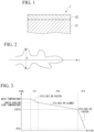
- the grain diameter of the ⁇ phase refers to the minor axis of a dendrite.
- the minor axis of the dendrite is the maximum value of dendrite widths that are measured in a direction orthogonal to the major axis direction of the dendrite as shown in FIG. 2 .
- a method for measuring the area ratio of the MgZn 2 phase is as described below.
- the surface of the plating layer of a sample cut to 30 mm ⁇ 30 mm is adjusted to be flat by mechanical polishing.
- the surface of the plating layer is chemically polished by colloidal polishing and is polished until this surface falls into a mirror surface state.
- the surface of the plating layer after the polishing is observed with a scanning electron microscope (SEM).
- SEM scanning electron microscope
- an element distribution image is captured using SEM-EDS at a magnification of 5000 times.
- phases where Mg and Zn coexist are specified as the MgZn 2 phases.
- the area ratio of the MgZn 2 phases that are contained in the visual field is calculated by binarization for which image analysis software is used.
- a method for measuring the area ratio of the ⁇ phase having the (111) ⁇ //(0001) MgZn2 orientation relationship to the adjacent MgZn 2 phase among the ⁇ phases having a grain diameter of 0.5 to 2 ⁇ m is as described below.
- the surface of the plating layer is mirror-polished and chemically polished as necessary.
- the polished surface is observed with SEM at a magnification of 5000 times.
- five visual fields where the ⁇ phase having a grain diameter of 0.5 to 2 ⁇ m can be visually recognized in an area ratio of 5% or more are selected.
- Crystal orientation analysis is carried out using EBSD on these visual fields.
- a (111) pole figure of the ⁇ phase and a (0001) pole figure of the MgZn 2 phase are obtained. These pole figures are compared, and a crystal orientation where the orientations of the ⁇ phase and the MgZn 2 phase match is selected.
- a crystal orientation where the crystal orientation pole figures match can be specified by the above procedure.
- An ⁇ phase having a crystal orientation within ⁇ 10° from this crystal orientation in the measurement system is shown on an IPF map.
- the image of this IPF map is binarized and image-analyzed, whereby it is possible to calculate the area ratio of the ⁇ phase having a crystal orientation within ⁇ 10° from the crystal orientation where the orientations of the ⁇ phase and the MgZn 2 phase match and having a grain diameter of 0.5 to 2 ⁇ m to the ⁇ phase having a grain diameter of 0.5 to 2 ⁇ m in the observed visual fields.
- the other constitutions of the hot-dip plating layer are not particularly limited as long as the area ratio of the ⁇ phase, the area ratio of the MgZn 2 phase, and the interface state between the ⁇ phase and the MgZn 2 phase are within the above-described ranges.
- the configuration of a normal hot-dip plated steel can be appropriately adopted for the hot-dip plating layer of the hot-dip plated steel according to the present embodiment.
- a method for manufacturing a hot-dip plated steel according to the present embodiment is not particularly limited. For example, according to manufacturing conditions to be described below, the hot-dip plated steel according to the present embodiment can be obtained.
- a base steel is immersed in a hot-dip plating bath.
- the chemical composition of the hot-dip plating bath may be appropriately adjusted so that the above-described chemical composition of the hot-dip plating layer can be obtained.
- the temperature of the hot-dip plating bath is also not particularly limited, and a temperature at which hot-dip plating can be carried out can be appropriately selected.
- the plating bath temperature may be set to a value higher than the melting point of the plating bath by about 20°C or more.
- the amount of the hot-dip plating layer attached can be controlled by controlling the lifting speed of the base steel.
- the amount of the hot-dip plating layer attached may be also controlled by carrying out wiping on the base steel to which the hot-dip plating layer has been attached as necessary.
- the amount of the hot-dip plating layer attached is not particularly limited and can be set, for example, within the above-described range.
- the hot-dip plating layer is cooled.
- the cooling is composed of first cooling, second cooling, and third cooling.
- molten metal (hot-dip plating layer) attached to the surface of the base steel is rapidly cooled.
- the molten metal is cooled in an accelerated manner to a rapid cooling stop temperature (controlled cooling stop temperature) within a temperature range of 360°C or higher and 520°C or lower by accelerated cooling means such as spraying of a cooling medium.
- the rapid cooling stop temperature is the temperature of the hot-dip plating layer when the accelerated cooling is stopped.
- the average cooling rate in the first cooling is set to 15 °C/sec or faster.
- the average cooling rate in the first cooling is a value obtained by dividing the difference between the temperature of the plating bath and the rapid cooling stop temperature by the elapsed time from when the base steel is lifted from the plating bath to when the accelerated cooling is stopped.
- the hot-dip plating layer is slowly cooled.
- the average cooling rate in a temperature range from the above-described rapid cooling stop temperature to 335°C is set to 5 °C/sec or slower.
- the average cooling rate in the temperature range from the rapid cooling stop temperature to 335°C is a value obtained by dividing the difference between the rapid cooling stop temperature and 335°C by a time required for the temperature of the hot-dip plating layer to drop from the rapid cooling stop temperature to 335°C.
- the above-described cooling rate can be achieved by, for example, leaving the hot-dip plating layer to the atmosphere after the accelerated cooling is stopped. However, in a case where the air temperature of a manufacturing environment is extremely low, a heat treatment may be required to decrease the temperature drop rate of the hot-dip plating layer.
- the hot-dip plating layer is rapidly cooled again.
- the average cooling rate in a temperature range from 335°C to 70°C is set to 70 °C/sec or faster.
- the average cooling rate in the temperature range from 335°C to 70°C is a value obtained by dividing the difference between 335°C and 70°C (265°C) by a time required for the temperature of the hot-dip plating layer to drop from 335°C to 70°C.
- the above-described cooling rate can be achieved by, for example, cooling the hot-dip plated steel with water when the temperature of the hot-dip plating layer lowers to near 335°C.
- the hot-dip plating layer When the hot-dip plating layer is cooled so as to satisfy the above-described conditions, it is possible to form a hot-dip plating layer where the amount of the ⁇ phase having the (111) ⁇ //(0001) MgZn2 orientation relationship is 25 area% or more.
- the present inventors presume that the reason therefor is as described below.
- the molten metal is rapidly cooled. This makes both the ⁇ phase and the MgZn 2 phase crystallize from the molten metal.
- the hot-dip plating layer in which both the ⁇ phase and the MgZn 2 phase have been crystallized is slowly cooled.
- the hot-dip plating layer containing a large amount of the ⁇ phase where the (111) ⁇ //(0001) MgZn2 orientation relationship has been established is rapidly cooled again. This makes it possible to suppress solid-phase transformation in which a ⁇ phase is precipitated from the ⁇ phase and to preserve the (111) ⁇ //(0001) MgZn2 orientation relationship.
- Base steels were immersed in a variety of hot-dip plating baths and lifted to attach hot-dip plating layers to the surfaces of the base steels, and then the hot-dip plating layers were cooled under a variety of conditions, thereby manufacturing a variety of hot-dip plated steels.
- the chemical compositions of the hot-dip plating layers were as shown in Table 1A and Table 1B. In a case where the Fe content of the hot-dip plating layer was less than 0.05%, a symbol "-" is shown in Table 1A and Table 1B. Manufacturing conditions were set as shown in Table 2A and Table 2B. In addition, the metallographic structures of the plating layers were evaluated, and the results are shown in Table 3A and Table 3B. Furthermore, the powdering resistance and corrosion resistance under running water of the hot-dip plated steels were evaluated, and the results are shown in Table 4A and Table 4B.
- the chemical compositions of the hot-dip plating layers and the metallographic structures of the hot-dip plating layers were evaluated by the above-described means. Some of the base steels were pre-plated with Ni before being hot-dip galvanizing. The composition of the Ni pre-plate is included in the chemical composition of the hot-dip plating layers disclosed in Table 1 and Table 1B.
- the powdering resistance was evaluated by the following means.
- the hot-dip plated steel was V-bent at 90° using a die having a bend radius of 5 mm, and a 24 mm-wide cellophane tape was pressed against and peeled off from a V-bent valley portion. In addition, the presence or absence of powdering was visually evaluated.
- a hot-dip plated steel for which a powdering exfoliation powder was not attached to the tape was evaluated as "AA”
- a hot-dip plated steel for which a powdering exfoliation powder was slightly attached was evaluated as "A”
- a hot-dip plated steel for which a powdering exfoliation powder was attached was evaluated as "B”.
- Hot-dip plated steels having an evaluation result of A or AA were determined as steels having excellent powdering resistance.
- the corrosion resistance under running water was evaluated by the following means.
- a test piece having a shape with dimensions of 200 mm ⁇ 100 mm ⁇ 0.8 mm was produced by cutting the hot-dip plated steel.
- a tape was stuck to 5 mm-wide ranges from the cut end surface on a surface opposite to an evaluation surface and on the evaluation surface so as to prevent contact with corrosive solutions.
- the test piece was placed on a table at an inclination angle of 60° with respect to the horizontal plane.
- a step of exposing the test piece to running water and a step of drying the test piece were alternately repeated. In the step of exposing the test piece to running water, a 0.5% NaCl solution was made to flow at a flow rate of 100 ml/min for 6 hours.
- test piece was left to stand for 18 hours.
- the testing environment was set to the atmosphere, and the temperature was held at 25°C.
- the corrosion weight loss per unit area of the plating layer was measured.
- a test piece for which the corrosion weight loss was 30 g/m 2 or less was evaluated as "AA”
- a test piece for which the corrosion weight loss was 60g/m 2 or less was evaluated as "A”
- a test piece for which the corrosion weight loss was more than 60g/m 2 was evaluated as "B”.
- Hot-dip plated steels having an evaluation result of A or AA were determined as steels having excellent corrosion resistance under running water.
- Plating bath temperature Cooling conditions Amount attached to single surface Average cooling rate from bath temperature to controlled cooling stop temperature Controlled cooling stop temperature Average cooling rate from controlled cooling stop temperature to 335°C Cooling rate at 335°C or lower (°C) (°C/sec) (°C) (°C/sec) (°C/sec) (g/m 2 ) b1 420 15 345 5 70 42 b2 465 15 420 5 70 53 b3 495 15 460 5 70 55 b4 520 15 460 5 70 85 b5 580 15 490 5 70 115 b6 450 15 460 5 70 99 b7 510 6 460 5 70 55 b8 510 15 460 15 70 95 b9 510 15 460 5 10 43 b10 510 15 440 5 70 29 b11 560 2 410 5 70 99 b12 510 15 440 15 70 20 Underlined parts indicate that the corresponding values are outside the ranges of preferable manufacturing conditions.
- Comparative Example b1 the amount of Al in the hot-dip plating layer was insufficient. Therefore, in Comparative Example b1, the ⁇ phase was insufficient. In addition, since crystal growth occurred in a state where the ⁇ phase and the MgZn 2 phase were not in contact with each other, in Comparative Example b1, the proportion of the ⁇ phase having an appropriate crystal orientation relationship with the MgZn 2 phase was also insufficient. As a result, in Comparative Example b1, both the powdering resistance and the corrosion resistance under running water were insufficient.
- Comparative Example b2 the amount of Mg in the hot-dip plating layer was insufficient. Therefore, in Comparative Example b2, the MgZn 2 phase was insufficient. As a result, in Comparative Example b2, the corrosion resistance under running water was insufficient.
- Comparative Example b3 the amount of Mg in the hot-dip plating layer was excessive. Therefore, in Comparative Example b3, the brittle MgZn 2 phase became excessive, and both the powdering resistance and the corrosion resistance under running water were insufficient.
- Comparative Example b4 the amount of Si in the hot-dip plating layer was excessive. Therefore, a large amount of a brittle Si-based compound was formed in the hot-dip plating layer of Comparative Example b3, and both the powdering resistance and the corrosion resistance under running water were insufficient.
- Comparative Example b5 the amount of Al in the hot-dip plating layer was excessive. Therefore, in Comparative Example b5, the amount of the ⁇ phase where crystals grew in a state where the ⁇ phase was not in contact with the MgZn 2 phase increased, and the proportion of the ⁇ phase having an appropriate crystal orientation relationship with the MgZn 2 phase became small. As a result, in Comparative Example b5, the corrosion resistance under running water was insufficient.
- Comparative Example b6 the amount of Ca in the hot-dip plating layer was excessive. Therefore, a large amount of a brittle Ca-based compound was formed in the hot-dip plating layer of Comparative Example b6, and both the powdering resistance and the corrosion resistance under running water were insufficient.
- Comparative Example b7 and Comparative Example b 11 the average cooling rate in the first cooling was insufficient. Therefore, in Comparative Example b7 and Comparative Example b 11, crystal growth occurred in a state where the ⁇ phase and the MgZn 2 phase were not in contact with each other, and the proportion of the ⁇ phase having an appropriate crystal orientation relationship with the MgZn 2 phase was insufficient. As a result, in Comparative Example b7 and Comparative Example b 11, the corrosion resistance under running water was insufficient. In addition, in Comparative Example b7, the powdering resistance was also insufficient.
- Comparative Example b8 and Comparative Example b12 the average cooling rate in the second cooling was excessive. Therefore, in Comparative Examples b8 and b 12, it was not possible to sufficiently grow the ⁇ phase and the MgZn 2 phase in a state of being in contact with each other, and the proportion of the ⁇ phase having an appropriate crystal orientation relationship with the MgZn 2 phase was insufficient. As a result, in Comparative Example b8 and Comparative Example b12, the corrosion resistance under running water was insufficient.
- Comparative Example b9 the average cooling rate in the third cooling was insufficient. Therefore, in Comparative Example b9, the ⁇ phase was separated into an Al-rich ⁇ phase and a Zn-rich ⁇ phase in the third cooling, and the proportion of the ⁇ phase having an appropriate crystal orientation relationship with the MgZn 2 phase was insufficient. As a result, in Comparative Example b9, the corrosion resistance under running water was insufficient.
- Comparative Example b10 the amount of Sn in the hot-dip plating layer was excessive. Therefore, in Comparative Example b10, a Sn-based compounds having low corrosion resistance was formed, and the corrosion resistance under running water was insufficient.
Landscapes
- Chemical & Material Sciences (AREA)
- Engineering & Computer Science (AREA)
- Organic Chemistry (AREA)
- Materials Engineering (AREA)
- Mechanical Engineering (AREA)
- Metallurgy (AREA)
- Chemical Kinetics & Catalysis (AREA)
- Physics & Mathematics (AREA)
- Thermal Sciences (AREA)
- Crystallography & Structural Chemistry (AREA)
- Oil, Petroleum & Natural Gas (AREA)
- Inorganic Chemistry (AREA)
- Coating With Molten Metal (AREA)
Priority Applications (1)
| Application Number | Priority Date | Filing Date | Title |
|---|---|---|---|
| EP24194567.4A EP4484584A1 (en) | 2021-09-07 | 2021-09-07 | Hot-dip galvanized steel material |
Applications Claiming Priority (3)
| Application Number | Priority Date | Filing Date | Title |
|---|---|---|---|
| EP21944420.5A EP4174203B1 (en) | 2021-09-07 | 2021-09-07 | Hot-dip galvanized steel material |
| PCT/JP2021/032749 WO2023037396A1 (ja) | 2021-09-07 | 2021-09-07 | 溶融めっき鋼材 |
| EP24194567.4A EP4484584A1 (en) | 2021-09-07 | 2021-09-07 | Hot-dip galvanized steel material |
Related Parent Applications (2)
| Application Number | Title | Priority Date | Filing Date |
|---|---|---|---|
| EP21944420.5A Division EP4174203B1 (en) | 2021-09-07 | 2021-09-07 | Hot-dip galvanized steel material |
| EP21944420.5A Division-Into EP4174203B1 (en) | 2021-09-07 | 2021-09-07 | Hot-dip galvanized steel material |
Publications (1)
| Publication Number | Publication Date |
|---|---|
| EP4484584A1 true EP4484584A1 (en) | 2025-01-01 |
Family
ID=81291673
Family Applications (2)
| Application Number | Title | Priority Date | Filing Date |
|---|---|---|---|
| EP24194567.4A Pending EP4484584A1 (en) | 2021-09-07 | 2021-09-07 | Hot-dip galvanized steel material |
| EP21944420.5A Active EP4174203B1 (en) | 2021-09-07 | 2021-09-07 | Hot-dip galvanized steel material |
Family Applications After (1)
| Application Number | Title | Priority Date | Filing Date |
|---|---|---|---|
| EP21944420.5A Active EP4174203B1 (en) | 2021-09-07 | 2021-09-07 | Hot-dip galvanized steel material |
Country Status (15)
| Country | Link |
|---|---|
| US (1) | US11814732B2 (pl) |
| EP (2) | EP4484584A1 (pl) |
| JP (1) | JP7056811B1 (pl) |
| KR (1) | KR102524791B1 (pl) |
| CN (2) | CN117280070B (pl) |
| AU (1) | AU2021463503B2 (pl) |
| CA (1) | CA3229519A1 (pl) |
| CO (1) | CO2024004134A2 (pl) |
| EC (1) | ECSP24016851A (pl) |
| ES (1) | ES2991302T3 (pl) |
| HU (1) | HUE069505T2 (pl) |
| MX (1) | MX2024002595A (pl) |
| PE (1) | PE20240737A1 (pl) |
| PL (1) | PL4174203T3 (pl) |
| WO (1) | WO2023037396A1 (pl) |
Families Citing this family (2)
| Publication number | Priority date | Publication date | Assignee | Title |
|---|---|---|---|---|
| WO2024219123A1 (ja) * | 2023-04-17 | 2024-10-24 | 日本製鉄株式会社 | 溶融めっき鋼材 |
| WO2025225565A1 (ja) * | 2024-04-23 | 2025-10-30 | 日本製鉄株式会社 | めっき鋼材 |
Citations (4)
| Publication number | Priority date | Publication date | Assignee | Title |
|---|---|---|---|---|
| WO2019221193A1 (ja) | 2018-05-16 | 2019-11-21 | 日本製鉄株式会社 | めっき鋼材 |
| US20190390303A1 (en) * | 2017-01-27 | 2019-12-26 | Nippon Steel Corporation | Coated steel product |
| WO2020213686A1 (ja) | 2019-04-19 | 2020-10-22 | 日本製鉄株式会社 | めっき鋼板 |
| US20210198780A1 (en) * | 2017-12-28 | 2021-07-01 | Nippon Steel Corporation | MOLTEN Zn-BASED PLATED STEEL SHEET HAVING SUPERIOR CORROSION RESISTANCE AFTER BEING COATED |
Family Cites Families (25)
| Publication number | Priority date | Publication date | Assignee | Title |
|---|---|---|---|---|
| JP5087813B2 (ja) | 2001-08-31 | 2012-12-05 | Jfeスチール株式会社 | めっき性に優れた高張力溶融亜鉛めっき鋼板およびその製造方法 |
| JP2003277905A (ja) | 2002-03-19 | 2003-10-02 | Jfe Steel Kk | 表面外観および曲げ加工性に優れた溶融Al−Zn系合金めっき鋼板およびその製造方法 |
| MXPA06010613A (es) | 2004-08-10 | 2006-12-15 | Sanbo Shindo Kogyo Kabushiki K | Fundicion de aleacion basada en cobre con granos de cristal refinados. |
| WO2009113489A1 (ja) | 2008-03-09 | 2009-09-17 | 三菱伸銅株式会社 | 銀白色銅合金及びその製造方法 |
| EP2388353B1 (en) * | 2009-01-16 | 2014-11-12 | Nippon Steel & Sumitomo Metal Corporation | HOT-DIP Zn-Al-Mg-Si-Cr ALLOY COATED STEEL MATERIAL WITH EXCELLENT CORROSION RESISTANCE |
| JP4998756B2 (ja) | 2009-02-25 | 2012-08-15 | Jfeスチール株式会社 | 加工性に優れた高強度溶融亜鉛めっき鋼板およびその製造方法 |
| CN103917674B (zh) | 2011-11-04 | 2015-06-03 | 三菱伸铜株式会社 | 铜合金热锻件 |
| KR101896857B1 (ko) | 2015-04-08 | 2018-09-07 | 신닛테츠스미킨 카부시키카이샤 | Zn-Al-Mg계 도금 강판 및 Zn-Al-Mg계 도금 강판의 제조 방법 |
| EP3369837B1 (en) * | 2015-10-26 | 2020-02-05 | Nippon Steel Corporation | Plated steel sheet |
| KR101767788B1 (ko) | 2015-12-24 | 2017-08-14 | 주식회사 포스코 | 내마찰성 및 내백청성이 우수한 도금 강재 및 그 제조방법 |
| KR101665912B1 (ko) * | 2016-03-22 | 2016-10-13 | 주식회사 포스코 | 내식성이 우수한 용융아연합금 도금강판 및 그 제조방법 |
| KR101818350B1 (ko) | 2016-06-08 | 2018-01-15 | 포항공과대학교 산학협력단 | 고내식 아연-마그네슘-알루미늄 합금 용융도금강판 도금층 상함량 측정방법 |
| US11555235B2 (en) * | 2017-01-27 | 2023-01-17 | Nippon Steel Corporation | Metallic coated steel product |
| JP6428975B1 (ja) * | 2017-03-17 | 2018-11-28 | 新日鐵住金株式会社 | めっき鋼板 |
| KR102266076B1 (ko) | 2017-03-17 | 2021-06-18 | 닛폰세이테츠 가부시키가이샤 | 도금 강판 |
| MY192929A (en) | 2017-07-05 | 2022-09-15 | Jfe Steel Corp | Steel sheet having a hot-dip zn-al-mg-based coating film excellent in terms of surface appearance and method for manufacturing the same |
| KR102235255B1 (ko) | 2017-12-26 | 2021-04-02 | 주식회사 포스코 | 내식성 및 표면 평활성이 우수한 아연합금도금강재 및 그 제조방법 |
| CN109112281A (zh) | 2018-08-08 | 2019-01-01 | 中国原子能科学研究院 | 一种包壳管焊接用含铌端塞材料及其制造方法 |
| TWI810414B (zh) | 2018-12-03 | 2023-08-01 | 日商Jx金屬股份有限公司 | 耐蝕性CuZn合金 |
| JP7277822B2 (ja) | 2019-04-19 | 2023-05-19 | 日本製鉄株式会社 | めっき鋼材 |
| CN113994018B (zh) | 2019-06-27 | 2022-09-02 | 日本制铁株式会社 | 镀覆钢材 |
| JP7381865B2 (ja) * | 2019-11-29 | 2023-11-16 | 日本製鉄株式会社 | Zn-Al-Mg系溶融めっき鋼板 |
| KR102658299B1 (ko) * | 2019-11-29 | 2024-04-18 | 닛폰세이테츠 가부시키가이샤 | Zn-Al-Mg계 용융 도금 강판 |
| JP7381864B2 (ja) | 2019-11-29 | 2023-11-16 | 日本製鉄株式会社 | Zn-Al-Mg系溶融めっき鋼板 |
| MX2022015392A (es) | 2020-06-09 | 2023-01-16 | Nippon Steel Corp | Acero chapado a base de zn-al-mg sumergido en caliente. |
-
2021
- 2021-09-07 HU HUE21944420A patent/HUE069505T2/hu unknown
- 2021-09-07 KR KR1020227045399A patent/KR102524791B1/ko active Active
- 2021-09-07 EP EP24194567.4A patent/EP4484584A1/en active Pending
- 2021-09-07 CA CA3229519A patent/CA3229519A1/en active Pending
- 2021-09-07 CN CN202180046313.9A patent/CN117280070B/zh active Active
- 2021-09-07 WO PCT/JP2021/032749 patent/WO2023037396A1/ja not_active Ceased
- 2021-09-07 CN CN202410403454.7A patent/CN118241139A/zh active Pending
- 2021-09-07 US US18/009,015 patent/US11814732B2/en active Active
- 2021-09-07 MX MX2024002595A patent/MX2024002595A/es unknown
- 2021-09-07 ES ES21944420T patent/ES2991302T3/es active Active
- 2021-09-07 EP EP21944420.5A patent/EP4174203B1/en active Active
- 2021-09-07 PE PE2024000334A patent/PE20240737A1/es unknown
- 2021-09-07 AU AU2021463503A patent/AU2021463503B2/en active Active
- 2021-09-07 PL PL21944420.5T patent/PL4174203T3/pl unknown
- 2021-09-07 JP JP2022504124A patent/JP7056811B1/ja active Active
-
2024
- 2024-03-01 EC ECSENADI202416851A patent/ECSP24016851A/es unknown
- 2024-04-03 CO CONC2024/0004134A patent/CO2024004134A2/es unknown
Patent Citations (4)
| Publication number | Priority date | Publication date | Assignee | Title |
|---|---|---|---|---|
| US20190390303A1 (en) * | 2017-01-27 | 2019-12-26 | Nippon Steel Corporation | Coated steel product |
| US20210198780A1 (en) * | 2017-12-28 | 2021-07-01 | Nippon Steel Corporation | MOLTEN Zn-BASED PLATED STEEL SHEET HAVING SUPERIOR CORROSION RESISTANCE AFTER BEING COATED |
| WO2019221193A1 (ja) | 2018-05-16 | 2019-11-21 | 日本製鉄株式会社 | めっき鋼材 |
| WO2020213686A1 (ja) | 2019-04-19 | 2020-10-22 | 日本製鉄株式会社 | めっき鋼板 |
Also Published As
| Publication number | Publication date |
|---|---|
| CN117280070B (zh) | 2024-04-19 |
| CN118241139A (zh) | 2024-06-25 |
| KR102524791B1 (ko) | 2023-04-24 |
| ES2991302T3 (es) | 2024-12-03 |
| CN117280070A (zh) | 2023-12-22 |
| CA3229519A1 (en) | 2023-03-16 |
| JP7056811B1 (ja) | 2022-04-19 |
| EP4174203C0 (en) | 2024-10-02 |
| WO2023037396A1 (ja) | 2023-03-16 |
| CO2024004134A2 (es) | 2024-07-18 |
| US20230203635A1 (en) | 2023-06-29 |
| AU2021463503B2 (en) | 2025-06-05 |
| JPWO2023037396A1 (pl) | 2023-03-16 |
| HUE069505T2 (hu) | 2025-03-28 |
| EP4174203B1 (en) | 2024-10-02 |
| EP4174203A4 (en) | 2023-09-06 |
| EP4174203A1 (en) | 2023-05-03 |
| US11814732B2 (en) | 2023-11-14 |
| MX2024002595A (es) | 2024-03-22 |
| PL4174203T3 (pl) | 2025-02-03 |
| KR20230038660A (ko) | 2023-03-21 |
| AU2021463503A1 (en) | 2024-03-28 |
| PE20240737A1 (es) | 2024-04-16 |
| ECSP24016851A (es) | 2024-04-30 |
Similar Documents
| Publication | Publication Date | Title |
|---|---|---|
| JP4874328B2 (ja) | 高耐食性溶融Zn系めっき鋼材 | |
| CN110268087A (zh) | 镀覆钢材 | |
| KR20050074974A (ko) | 표면 평활성과 성형성이 우수한 고내식성 용융 도금 강재와용융 도금 강재의 제조 방법 | |
| EP4163413B1 (en) | Plated steel material | |
| EP4234736B1 (en) | Plated steel sheet | |
| JP2023507962A (ja) | 加工部耐食性に優れたZn-Al-Mg系溶融合金めっき鋼材及びその製造方法 | |
| WO2020213680A1 (ja) | めっき鋼材 | |
| CN113383105A (zh) | 镀层钢板 | |
| EP4174203B1 (en) | Hot-dip galvanized steel material | |
| JPWO2020213688A1 (ja) | めっき鋼板 | |
| JP4461866B2 (ja) | 耐食性および曲げ加工性に優れた溶融Zn−Al系合金めっき鋼板およびその製造方法 | |
| CN117280069B (zh) | 热浸镀钢材 | |
| TWI825475B (zh) | 熔融鍍敷鋼材 | |
| KR102870496B1 (ko) | 도금 강판 | |
| JP7633587B1 (ja) | めっき鋼材および太陽光発電用架台 | |
| JP7499849B2 (ja) | 溶融Al-Zn系めっき鋼板及びその製造方法 | |
| TWI864834B (zh) | 鍍敷鋼板 | |
| AU2024250020A1 (en) | Plated steel material | |
| WO2025225005A1 (ja) | めっき鋼材 | |
| CN121002225A (zh) | 热浸镀钢材 | |
| AU2024251523A1 (en) | Plated steel material | |
| KR20240113952A (ko) | 용융 Al-Zn 계 도금 강판 및 그 제조 방법 | |
| JP2025005266A (ja) | 溶融Zn-Al系めっき鋼板及びその製造方法 |
Legal Events
| Date | Code | Title | Description |
|---|---|---|---|
| PUAI | Public reference made under article 153(3) epc to a published international application that has entered the european phase |
Free format text: ORIGINAL CODE: 0009012 |
|
| STAA | Information on the status of an ep patent application or granted ep patent |
Free format text: STATUS: REQUEST FOR EXAMINATION WAS MADE |
|
| 17P | Request for examination filed |
Effective date: 20240904 |
|
| AC | Divisional application: reference to earlier application |
Ref document number: 4174203 Country of ref document: EP Kind code of ref document: P |
|
| AK | Designated contracting states |
Kind code of ref document: A1 Designated state(s): AL AT BE BG CH CY CZ DE DK EE ES FI FR GB GR HR HU IE IS IT LI LT LU LV MC MK MT NL NO PL PT RO RS SE SI SK SM TR |