EP4483751A2 - Brosse interdentaire - Google Patents
Brosse interdentaire Download PDFInfo
- Publication number
- EP4483751A2 EP4483751A2 EP24212606.8A EP24212606A EP4483751A2 EP 4483751 A2 EP4483751 A2 EP 4483751A2 EP 24212606 A EP24212606 A EP 24212606A EP 4483751 A2 EP4483751 A2 EP 4483751A2
- Authority
- EP
- European Patent Office
- Prior art keywords
- bristle
- support core
- handle
- support
- bristle field
- Prior art date
- Legal status (The legal status is an assumption and is not a legal conclusion. Google has not performed a legal analysis and makes no representation as to the accuracy of the status listed.)
- Pending
Links
Images


Classifications
-
- A—HUMAN NECESSITIES
- A46—BRUSHWARE
- A46B—BRUSHES
- A46B1/00—Brush bodies and bristles moulded as a unit
-
- A—HUMAN NECESSITIES
- A46—BRUSHWARE
- A46B—BRUSHES
- A46B3/00—Brushes characterised by the way in which the bristles are fixed or joined in or on the brush body or carrier
- A46B3/005—Bristle carriers and bristles moulded as a unit
-
- A—HUMAN NECESSITIES
- A46—BRUSHWARE
- A46B—BRUSHES
- A46B5/00—Brush bodies; Handles integral with brushware
- A46B5/02—Brush bodies; Handles integral with brushware specially shaped for holding by the hand
-
- A—HUMAN NECESSITIES
- A46—BRUSHWARE
- A46B—BRUSHES
- A46B5/00—Brush bodies; Handles integral with brushware
- A46B5/02—Brush bodies; Handles integral with brushware specially shaped for holding by the hand
- A46B5/026—Grips or handles having a nonslip section
-
- A—HUMAN NECESSITIES
- A46—BRUSHWARE
- A46D—MANUFACTURE OF BRUSHES
- A46D3/00—Preparing, i.e. Manufacturing brush bodies
-
- B—PERFORMING OPERATIONS; TRANSPORTING
- B29—WORKING OF PLASTICS; WORKING OF SUBSTANCES IN A PLASTIC STATE IN GENERAL
- B29C—SHAPING OR JOINING OF PLASTICS; SHAPING OF MATERIAL IN A PLASTIC STATE, NOT OTHERWISE PROVIDED FOR; AFTER-TREATMENT OF THE SHAPED PRODUCTS, e.g. REPAIRING
- B29C45/00—Injection moulding, i.e. forcing the required volume of moulding material through a nozzle into a closed mould; Apparatus therefor
- B29C45/14—Injection moulding, i.e. forcing the required volume of moulding material through a nozzle into a closed mould; Apparatus therefor incorporating preformed parts or layers, e.g. injection moulding around inserts or for coating articles
- B29C45/14549—Coating rod-like, wire-like or belt-like articles
-
- A—HUMAN NECESSITIES
- A46—BRUSHWARE
- A46B—BRUSHES
- A46B15/00—Other brushes; Brushes with additional arrangements
- A46B15/0093—Magazins or sets of brushes components, e.g. plurality of brushes linked as a package
-
- A—HUMAN NECESSITIES
- A46—BRUSHWARE
- A46B—BRUSHES
- A46B15/00—Other brushes; Brushes with additional arrangements
- A46B15/0095—Brushes with a feature for storage after use
-
- A—HUMAN NECESSITIES
- A46—BRUSHWARE
- A46B—BRUSHES
- A46B2200/00—Brushes characterized by their functions, uses or applications
- A46B2200/10—For human or animal care
- A46B2200/1066—Toothbrush for cleaning the teeth or dentures
- A46B2200/108—Inter-dental toothbrush, i.e. for cleaning interdental spaces specifically
-
- A—HUMAN NECESSITIES
- A46—BRUSHWARE
- A46B—BRUSHES
- A46B9/00—Arrangements of the bristles in the brush body
- A46B9/02—Position or arrangement of bristles in relation to surface of the brush body, e.g. inclined, in rows, in groups
-
- B—PERFORMING OPERATIONS; TRANSPORTING
- B29—WORKING OF PLASTICS; WORKING OF SUBSTANCES IN A PLASTIC STATE IN GENERAL
- B29C—SHAPING OR JOINING OF PLASTICS; SHAPING OF MATERIAL IN A PLASTIC STATE, NOT OTHERWISE PROVIDED FOR; AFTER-TREATMENT OF THE SHAPED PRODUCTS, e.g. REPAIRING
- B29C45/00—Injection moulding, i.e. forcing the required volume of moulding material through a nozzle into a closed mould; Apparatus therefor
- B29C45/14—Injection moulding, i.e. forcing the required volume of moulding material through a nozzle into a closed mould; Apparatus therefor incorporating preformed parts or layers, e.g. injection moulding around inserts or for coating articles
- B29C45/14065—Positioning or centering articles in the mould
-
- B—PERFORMING OPERATIONS; TRANSPORTING
- B29—WORKING OF PLASTICS; WORKING OF SUBSTANCES IN A PLASTIC STATE IN GENERAL
- B29C—SHAPING OR JOINING OF PLASTICS; SHAPING OF MATERIAL IN A PLASTIC STATE, NOT OTHERWISE PROVIDED FOR; AFTER-TREATMENT OF THE SHAPED PRODUCTS, e.g. REPAIRING
- B29C45/00—Injection moulding, i.e. forcing the required volume of moulding material through a nozzle into a closed mould; Apparatus therefor
- B29C45/16—Making multilayered or multicoloured articles
- B29C45/1671—Making multilayered or multicoloured articles with an insert
-
- B—PERFORMING OPERATIONS; TRANSPORTING
- B29—WORKING OF PLASTICS; WORKING OF SUBSTANCES IN A PLASTIC STATE IN GENERAL
- B29C—SHAPING OR JOINING OF PLASTICS; SHAPING OF MATERIAL IN A PLASTIC STATE, NOT OTHERWISE PROVIDED FOR; AFTER-TREATMENT OF THE SHAPED PRODUCTS, e.g. REPAIRING
- B29C45/00—Injection moulding, i.e. forcing the required volume of moulding material through a nozzle into a closed mould; Apparatus therefor
- B29C45/16—Making multilayered or multicoloured articles
- B29C45/1676—Making multilayered or multicoloured articles using a soft material and a rigid material, e.g. making articles with a sealing part
-
- B—PERFORMING OPERATIONS; TRANSPORTING
- B29—WORKING OF PLASTICS; WORKING OF SUBSTANCES IN A PLASTIC STATE IN GENERAL
- B29C—SHAPING OR JOINING OF PLASTICS; SHAPING OF MATERIAL IN A PLASTIC STATE, NOT OTHERWISE PROVIDED FOR; AFTER-TREATMENT OF THE SHAPED PRODUCTS, e.g. REPAIRING
- B29C45/00—Injection moulding, i.e. forcing the required volume of moulding material through a nozzle into a closed mould; Apparatus therefor
- B29C45/17—Component parts, details or accessories; Auxiliary operations
- B29C45/26—Moulds
- B29C45/2626—Moulds provided with a multiplicity of narrow cavities connected to a common cavity, e.g. for brushes, combs
-
- B—PERFORMING OPERATIONS; TRANSPORTING
- B29—WORKING OF PLASTICS; WORKING OF SUBSTANCES IN A PLASTIC STATE IN GENERAL
- B29C—SHAPING OR JOINING OF PLASTICS; SHAPING OF MATERIAL IN A PLASTIC STATE, NOT OTHERWISE PROVIDED FOR; AFTER-TREATMENT OF THE SHAPED PRODUCTS, e.g. REPAIRING
- B29C45/00—Injection moulding, i.e. forcing the required volume of moulding material through a nozzle into a closed mould; Apparatus therefor
- B29C45/17—Component parts, details or accessories; Auxiliary operations
- B29C45/26—Moulds
- B29C45/27—Sprue channels ; Runner channels or runner nozzles
- B29C45/2701—Details not specific to hot or cold runner channels
- B29C45/2708—Gates
-
- B—PERFORMING OPERATIONS; TRANSPORTING
- B29—WORKING OF PLASTICS; WORKING OF SUBSTANCES IN A PLASTIC STATE IN GENERAL
- B29K—INDEXING SCHEME ASSOCIATED WITH SUBCLASSES B29B, B29C OR B29D, RELATING TO MOULDING MATERIALS OR TO MATERIALS FOR MOULDS, REINFORCEMENTS, FILLERS OR PREFORMED PARTS, e.g. INSERTS
- B29K2021/00—Use of unspecified rubbers as moulding material
- B29K2021/003—Thermoplastic elastomers
-
- B—PERFORMING OPERATIONS; TRANSPORTING
- B29—WORKING OF PLASTICS; WORKING OF SUBSTANCES IN A PLASTIC STATE IN GENERAL
- B29K—INDEXING SCHEME ASSOCIATED WITH SUBCLASSES B29B, B29C OR B29D, RELATING TO MOULDING MATERIALS OR TO MATERIALS FOR MOULDS, REINFORCEMENTS, FILLERS OR PREFORMED PARTS, e.g. INSERTS
- B29K2101/00—Use of unspecified macromolecular compounds as moulding material
- B29K2101/12—Thermoplastic materials
-
- B—PERFORMING OPERATIONS; TRANSPORTING
- B29—WORKING OF PLASTICS; WORKING OF SUBSTANCES IN A PLASTIC STATE IN GENERAL
- B29L—INDEXING SCHEME ASSOCIATED WITH SUBCLASS B29C, RELATING TO PARTICULAR ARTICLES
- B29L2031/00—Other particular articles
- B29L2031/42—Brushes
Definitions
- the present invention relates to an interdental brush according to claim 1.
- the document WO 98/16169 discloses an interdental cleaner which consists of an elongated, rod-shaped carrier made of a first plastic material, which is covered in partial areas of its surface by at least one insert or overlay made of a second plastic material which is softer than the first plastic material.
- the insert can be arranged in a recess formed in the carrier and held in a form-fitting manner with it. If the first plastic material of the carrier and/or the second plastic material of the insert or overlay contains one or more additives, the cleaning and care effect can be varied and optimized.
- the second plastic material of the insert or overlay is sprayed onto the first plastic material of the carrier, whereby the carrier and the insert or overlay can be produced in a two-component injection molding process.
- a known cleaning instrument for a tooth root canal has a head section and an adjoining cleaning section with a shaft that is provided with bristles on its outer surface.
- the shaft is formed as a single piece together with the bristles.
- the document further reveals WO 2008/146968 A a method and a tool for producing a mascara brush.
- the tool has an upper mold box and a lower mold box which, when closed, together form cavities for producing the application heads by casting.
- a wick made of ceramic or plastic is inserted into the lower mold box and after the upper and lower mold boxes are brought together, a soft material is injected into the cavities.
- the tool has a press plate which interacts with the upper mold box, with feed openings leading from the space formed by the press plate and the upper mold box through the upper mold box into the cavities.
- Material which is liquefied under pressure is inserted between the press plate and the upper mold box. The material is liquefied by moving the press plate and the mold box towards one another and the liquid material is pressed through the connecting openings into the cavities.
- the brushes can be mascara brushes, medical brushes, cosmetic brushes, body care brushes, cleaning brushes, household brushes, etc.
- the solution according to the invention comprises a method for producing a brush, in particular an interdental brush, which has a bristle support stem defining a longitudinal direction with an elongated support core, a bristle field with bristles protruding from the bristle support stem and a neck element connecting the support core to a handle, with the following steps: injection molding the handle, the neck element and the support core integrally from a first plastic component, inserting the support core in the longitudinal direction through a bristle field cavity opening of an injection molding tool into a bristle field cavity, fixing the support core inserted into the bristle field cavity to prevent movement of the support core in the longitudinal direction, and applying a second plastic component from an injection point of the injection molding tool to the support core for the integral formation of a layer on the support core and the bristles protruding from it; and a brush, in particular an interdental brush, having a bristle support stem defining a longitudinal direction with an elongated support core, a bristle field with br
- the solution according to the invention also comprises a product group having a plurality of brushes, in particular interdental brushes, wherein the handles of the adjacent brushes are each connected via one, preferably two, material bridges made of the first plastic component, and a product group having a plurality of brushes, in particular interdental brushes, wherein the handles of the adjacent brushes are each connected via a material bridge made of the first plastic component and a material bridge made of the second plastic component.
- a product group consists of three to eight products arranged in a row, preferably five to six products. For reasons of For the sake of simplicity, the figures are shown with only five products each.
- the solution according to the invention further comprises a method for producing a brush, in particular an interdental brush, which has a bristle support stem defining a longitudinal direction with an elongated support core, a bristle field with bristles protruding from the bristle support stem and a neck element connecting the support core to a handle, with the following steps: injection molding the handle, the neck element and the support core integrally from a first plastic component in a first injection molding cavity, transferring the injected part into a further cavity of an injection molding tool with bristle cavities, fixing the part introduced into the bristle field cavity to prevent movement of the support core in the longitudinal direction, and applying a second plastic component from an injection point of the injection molding tool to the support core to integrally form a layer on the support core and the bristles protruding from it.
- the transfer in the injection molding tool preferably takes place with a transport bar, which moves the at least partially manufactured products after a lifting movement from the cavity by a translational displacement or a rotation to another cavity, where they are placed in the cavity by means of a stroke.
- the transport bar is preferably part of the cavity, which means that the transport bar forms part of the molding geometry at least in the first injection molding process.
- the interface between the product and the transport system can be arranged, for example, in the handle or in the neck or as a combination of these.
- the often desired individualization of the product can be achieved, for example, by using interchangeable shaping parts in the handle or neck.
- interchangeable shaping parts for example, lettering or other surface geometries can be formed in this way. These elements can be arranged both in the transport bar and in the actual cavity.
- the manufacturing process of the above-mentioned products is completed after injection molding to the extent that usable products are available. Accordingly, the product can be packaged after injection molding.
- the products are preferably packaged in a box that is presented to the end consumer.
- the products are arranged lying or standing directly next to each other.
- the packaging process can be linked inline, i.e. linked, or offline in a separate step.
- injection molding and packaging are linked.
- the products are not removed from the machine until they are completely packaged.
- storage, transport, etc. take place after injection molding before packaging.
- a hard plastic is preferably used as the first plastic component, from which the handle, the support core and the holding element are usually integrally formed, and a soft component is preferably used for the second plastic component, from which the layer or the bristles protruding from it are formed. It is of course also possible to use a further, third component, for example in the area of the handle, to increase the grip and improve ergonomics, or in the area of the bristle field in the form of further cleaning elements or other functional elements. Examples of the materials that can be considered in this context are listed further down in the general description section.
- each product can be manufactured in a single cavity and each product can be accommodated individually in the sales unit.
- several products are arranged next to one another and the products are connected via material bridges in the handle area.
- the longitudinal axes of the brushes are preferably arranged parallel.
- one, two or three material bridges are provided (although more are conceivable). These primarily give the product groups stability.
- the products are also separated at the material bridges for use. Since separating the individual brushes can create edges that could injure fine tissue such as the oral mucosa, the material bridges are regularly arranged in the handle. Preferably, the material bridges are each made from the same component.
- the material bridges can be rectangular or oval in cross-section, the cross-section preferably has a larger and a smaller length and the larger length of the cross-section is preferably in the direction of the longitudinal axis of the product.
- the material bridges can also comprise elements to assist in the separation process, such as notches or perforations as predetermined breaking points.
- the second plastic component surrounds the preferably bristle-free neck element at most partially.
- the support core, the neck element and the handle are injection molded in a cavity of the injection molding tool that is separate from the bristle field cavity.
- the layer is formed such that it forms a sheath of the supporting core in the region of the bristle stem.
- Such a coating can be used to achieve a particularly good and secure fit on the supporting core.
- the second component can also be selected in terms of its shrinkage behavior so that it shrinks onto the supporting core.
- the support core is centered in the bristle field cavity by means of bristle field tool parts, preferably by means of support elements projecting in the direction towards the interior of the bristle field cavity, at a plurality of support points spaced apart from one another in the longitudinal direction.
- the support points are preferably arranged between the bristles.
- the support core moves in the radial direction (i.e. away from the longitudinal axis) and possibly closes the openings for the bristles to be formed.
- the fixing of the support core in the region of the handle preferably takes place at locations where only one plastic component is present.
- the first and second plastic components consist of a hard material, a hard material and a semi-hard material or a hard material and a soft material.
- the material combinations selected depend on the specific application and the materials used are specified below in the general description section.
- a PE-PE material pairing is possible, whereby, for example, an HDPE is used for the first material component and an LLDPE is used for the second material component.
- a PP-TPE material pairing is possible.
- the materials used can be water-soluble and edible and can be made up, for example, entirely or partially of hydrocoloids, starch, gum arabic, polyvinyl alcohol, polyox.
- Agents that can be used as a coating or as an ingredient for the above-mentioned materials include color, flavor, tooth cleaning fluid, toothpaste, active ingredients.
- the support core has a smaller diameter than the neck element.
- the layer is sprayed or applied to the supporting core flush with the neck element.
- the flush finish of the layer with the neck element is more comfortable to handle and offers a more visually advantageous design.
- the injection point of the second plastic component is located at the front end of the handle facing the neck element.
- the choice of injection point is determined by the design of the product, the shot weight and the capabilities of the processing machine. Both hot runner and cold runner systems can be used.
- the sprue system In classic injection molding tools with a cold runner system, the sprue system is not thermally insulated from the rest of the tool. This means that both the tool and the sprue system inside it are tempered to temperatures well below the processing temperatures of the plastic. This means that the thermoplastic also solidifies in the sprue system during the production of a component.
- the sprue system In a hot runner system, the sprue system is thermally separated from the rest of the tool and heated separately so that the plastic melt in the sprue system remains permanently flowable. This means that the plastic in the sprue system does not solidify and no sprue remains on the component. Furthermore, longer flow paths can be achieved with the hot runner systems because the pressure loss in the sprue system is not increased by cooling the melt and the associated increase in viscosity.
- the plastic component of the casing covers a small part of the surface on the handle, while on the back of the interdental brush it covers a significant part of the surface of one side on the neck element before finally covering the surface in the bristle field section. completely covered.
- the parts injection-molded from the first plastic component may have corresponding depressions or channels that enable or support the flow of the second plastic component.
- correspondingly identical injection molding tools are used.
- the injection nozzle is arranged in the handle cavity and, due to the flow path, a hot runner system is preferably used.
- the injection point of the second plastic component is located at the free end of the support core or at the end of the support core facing the neck element.
- injection point is located at the free end of the support core, a separate injection point will be provided for each brush.
- a cold runner system is generally used here, with additional means in the tool or during post-processing to separate the product from the sprue.
- Punches or cutters are generally considered as separating agents.
- the injection nozzles are therefore each arranged in the bristle field cavity and both a tunnel sprue and a film sprue or other known sprue types can be used.
- the injection point of the second plastic component is located at the rear end of the handle, facing away from the neck element.
- the spray nozzle is again arranged in the handle cavity. Due to the relatively long flow path, a hot runner system is usually used.
- the second plastic component covers a large part of the surface of the handle and a significant part of the surface of one side on the back of the interdental brush on the neck element, before completely covering the surface in the bristle field section.
- the second plastic component is placed in corresponding recesses or a hole in the handle, where it forms a section with increased grip.
- the trough can be designed with a two-component or three-component coating to further improve grip and ergonomics.
- transitions can be provided, in the form of soft transitions from the handle, or hard transitions from the handle, such as with a recess.
- closed or open troughs can be provided, whereby in the closed version the edge of the trough is continuous and in the open version the trough is open on at least one side (for example guides on the left and right in the direction of the longitudinal axis). It is also conceivable that the trough is open at the front and back.
- troughs and holes are also possible, such as holes within a trough.
- the support core and preferably also the bristle stem, taper towards their end facing away from the neck element.
- the tapered design of the supporting core and preferably also of the bristle stem ensure greater variability of the brush and may help to ensure that the brush can be inserted more easily into the interdental area.
- the handle has a notch at its end facing away from the neck element, which is preferably provided with a border made of a soft component.
- the notch allows the brush to be attached to a holder or a glass or cup.
- the edge with the soft component can increase the grip when attaching it and provide protection against scratches or damage.
- the bristles protrude in a non-radial manner from the longitudinal axis of the supporting core.
- the individual bristles or rows of bristles essentially protrude vertically from the longitudinal axis of the supporting core or they lie horizontally within a plane that runs through the longitudinal axis or below the longitudinal axis. In this way, the cleaning effect of the brush in the critical areas between the teeth can be improved.
- the bristles preferably decrease in length in the direction of the end of the bristle stem facing away from the neck element.
- This measure also serves to improve the cleaning effect in the spaces between the teeth, as the brush can adapt better in its shape.
- two rows of bristles protrude substantially horizontally from the support core in a plane below the longitudinal axis of the support core.
- three rows of bristles are arranged on the upper side of the support core, which rows of bristles converge in the direction of the end of the bristle stem facing away from the neck element and which preferably protrude substantially vertically from the upper side.
- the second plastic component is injection-molded onto the front end of the handle facing the neck element, wherein the second plastic component covers a small part of the surface on the handle, while it covers a substantial part of the surface on the back side of the neck element and covers the surface of the support core completely, or with the exception of a lower side.
- the second plastic component is injection-molded onto the front end of the support core facing away from the neck element, wherein the second plastic component covers the surface of the support core completely, or with the exception of a lower side.
- two rows of bristles are arranged on the upper side of the support core, which are directed towards the end of the bristle stem facing away from the neck element. converge and which preferably protrude from the top at an outward angle.
- the two rows of bristles converge towards the free end of the core and the length of the individual bristles decreases towards the free end of the core.
- This variant is a little easier to manufacture than the variant with three rows of bristles on the top of the core. It also results in a slightly different cleaning effect.
- the number of rows of bristles can be chosen as desired, with a number of two to nine being preferred and a number of three to five being even more preferred.
- the angle between the individual rows of bristles is a maximum of 180°, i.e. the angle between the two furthest rows of bristles. In another preferred embodiment, the angle is between 0 and 90°. For the rows arranged in the middle (on the top), the angle may be between 0 and 20°; for the rows arranged at the edge, the angle is preferably between 60 and 85°.
- Lamellas made of the second material component can also be arranged on the supporting core.
- the slats can be integrated in the bristle field in various forms.
- the slats can run in a spiral around the supporting core, they can be arranged in a plate shape around the supporting core - in this way, several slats can be arranged one behind the other.
- longitudinal slats that extend along the longitudinal axis.
- Slats can generally be straight or wave-shaped, the contour can be closed or open.
- the slats can also form a height profile.
- the slats can be arranged in combination with the other cleaning elements mentioned, in particular the slats can be arranged between the bristles.
- a length of 35 to 70 mm is preferred and a length of 40 to 55 mm is most preferred.
- the height (including the bristle area) is preferably between 0.8 to 2.8 mm and most preferably between 1 and 2 mm.
- the width of the brush according to the invention is preferably between 3 and 12 mm and most preferably between 5 and 8 mm.
- the second plastic component is injection molded onto the rear end of the handle facing away from the neck element, wherein the second plastic component covers a large part of the surface on the handle, while on the rear side on the neck element it covers a substantial part of the surface and covers the surface of the support core completely, or with the exception of a lower side.
- a brush in particular an interdental brush, comprising a handle, a neck element and a support core, wherein the neck element connects the handle and the support core and wherein a bristle field is applied to the support core, and wherein the handle has a notch at its end facing away from the neck part.
- the notch is surrounded by two side flanks of the handle, which are preferably designed to be flexible or springy in the form of clamping arms.
- the flexibility of the two clamping arms can be designed by their geometry and/or by the selected plastic materials or material combinations.
- the base body which in any case comprises the handle and the neck element (these can, however, also be injection-molded integrally with the supporting core), is regularly formed from a plastic component, preferably a hard material.
- the notch is preferably surrounded by a border made of a soft component to ensure a better hold.
- the notch can also be designed like a membrane with a soft component layer that forms a lip-like shape around the object being inserted.
- the surface in the area of the notch can be designed in such a way that this area contains a recess for holding the brush.
- surface elements such as slats, knobs or similar can be arranged in the area of the notch to further improve the grip.
- the notch functional element can also be used in manual oral care devices in general.
- the notch functional element can also be used in manual oral care devices in general.
- other interdental cleaning devices toothbrushes, flossers, etc.
- a brush in particular an interdental brush, which has a bristle support stem defining a longitudinal direction with a support core running in the longitudinal direction and a bristle field with bristles protruding from the bristle support stem, is produced by injection molding.
- a bristle field cavity which is used to produce the bristle support stem and the bristles, is closed. This is done by moving the tool parts of the injection molding tool that delimit the bristle field cavity into the closed state.
- the bristle field cavity closed in this way has a bristle field cavity opening.
- a support core arranged with its longitudinal extension in the longitudinal direction is introduced in the longitudinal direction through the bristle field cavity opening into the closed bristle cavity.
- the introduced support core protrudes with a section from the bristle field cavity beyond the bristle field cavity opening.
- an injection molding tool is provided with at least two bristle field tool parts which, in the closed state, delimit the - closed - bristle field cavity.
- the bristle field cavity has a bristle field cavity opening on one end face. This is located in the longitudinal direction at one end of the bristle field cavity.
- the plastic is injected in such a way that it flows through the bristle field cavity opening into the bristle field cavity.
- the end of the support core located in the bristle field cavity is particularly preferably completely overmolded with plastic, so that the sheath forms a kind of cap around the support core at the free end of the bristle support stem.
- the support core is held - in the longitudinal direction - outside the bristle field to be formed by means of the fixing element and the plastic is injected in such a way that it flows through the bristle field cavity opening into the bristle field cavity.
- the support core is thus held upstream of the bristles to be injected, which enables the support core to extend over at least approximately the entire length of the bristle field cavity without the risk of it being bent by the plastic flowing into the bristle field cavity.
- the bristle field cavity can have a bristle field section and, in the direction of the bristle field cavity opening, a neck section immediately adjacent to the latter.
- the bristle field section contains the part of the interdental brush which has the injected bristles and which is intended to be inserted into the interdental spaces when the interdental brush is used.
- the neck section can thus be made larger than the diameter of the bristle support stem in the bristle field section.
- the injection molding tool has at least one neck tool part and the support core is fixed in the region of the neck tool part by means of the fixing element during injection of the plastic.
- the neck tool part is located on the side of the bristle field tool part on which the bristle field cavity opening is located.
- the injection molding tool has a cap tool part with a cap cavity, which serves to form the layer, for example the sheath at the free end of the bristle support stem.
- the cap tool part lies directly on the bristle field tool part.
- the fixing element is formed by two clamping dies which are diametrically opposite one another in the longitudinal direction and can be moved from a rest position towards one another into a clamping position in order to hold the support core in a clamping position.
- the direction of movement of the clamping dies runs along a common straight line which runs at right angles to the longitudinal direction. The direction of movement is preferably parallel to the opening direction of the handle cavity and the neck cavity.
- the clamping punches grip into the interior of the neck cavity in their clamping position and are surrounded by plastic during injection molding.
- the clamping punches seal against the support core in such a way that the plastic cannot flow into the clamping area when it flows around the punch pair.
- the support core is completely enclosed in the circumferential direction by the clamping stamps moved into the clamping position, so that a relevant fixing section of the support core remains free of plastic.
- the support core lies freely - without being covered by the plastic.
- the support core lies so deep in the passage or recess that the risk of a galvanic shock when it touches the teeth is averted, since the teeth cannot touch it.
- the clamping stamps preferably have teeth or tooth gaps in the end regions facing each other, which engage with each other in the clamping position.
- the support core is centered in the bristle field cavity - in the bristle field section - by means of the bristle field tool parts at several support points spaced apart from one another in the longitudinal direction.
- the bristle field tool parts preferably have support elements that protrude in the direction towards the interior of the bristle field cavity.
- the support elements protrude between 0.08 mm and 0.16 mm, particularly preferably between 0.1 mm and 0.14 mm, from the lateral surface of the part of the bristle field cavity defining the bristle support stem.
- the support elements are preferably designed with respect to the support core in such a way that, measured in the radial direction, a gap of 0.01 mm to 0.03 mm, particularly preferably between 0.015 mm and 0.025 mm, remains between the support elements and the centric or centrically conceived bristle support stem.
- This allows the support core to be introduced longitudinally into the bristle field cavity and between the support elements without causing any obstruction or bending occurs.
- This also allows a thin skin of plastic to form on the supporting core of the support elements when the plastic is injected.
- the support core is preferably supported by the support elements in succession at an angle.
- the offset is preferably 90°.
- the support elements are spaced apart from one another in the longitudinal direction and there are no support elements opposite one another in the radial direction.
- the plastic can therefore flow practically unhindered from the bristle field cavity opening through the bristle field cavity, since it is restricted in cross-section at a maximum of one point.
- the support elements form support points that are spirally formed around the bristle support stem.
- the support points are arranged such that the distance between two support points on the same side is between 4 and 16 times, preferably 4 times, a bristle spacing.
- the last support point towards the free end of the supporting core is preferably located directly after the last bristle level or directly in front of the last bristle level.
- the support points are preferably arranged regularly. However, it is also possible that the distance between the support points in the longitudinal direction is not always the same.
- the support elements are preferably designed to be identical across the entire bristle field. Their number is determined by the length of the bristle support stem and the distance between the support points.
- Bristle holes are understood to mean those parts of the bristle field cavity which extend from the surface area determining the bristle-bearing stem and which serve to form the bristles.
- the supporting core is formed by a metal wire, preferably made of a rust-proof or rust-resistant spring steel.
- the most preferred steel is 1.4310.
- the yield strength of the metallic wire should be greater than 2000 N/mm2. This ensures a good restoring moment when bending the bristle support stem in the application and prevents the support core from breaking when bent multiple times.
- the supporting core can also be made of plastic, ceramic or carbon composite fibers.
- Plastic support cores can be manufactured by injection molding or extrusion.
- a reinforced plastic is used to achieve the necessary stiffness and hardness.
- Glass fibers or glass beads, for example, can be used to reinforce the plastic.
- the injection molding or extrusion process for a plastic support core is carried out upstream of the injection molding process for the bristle field and can be separate or integrated into the same injection molding tool (two or multi-component tool).
- the plastic support core can have a shape that differs from a wire and can define a significant portion of the handle part and possibly its surface.
- a handle part of the interdental brush is also manufactured using the plastic during injection molding of the bristle field.
- the handle part is injection molded in a handle tool part, which is also referred to here as the second tool part.
- the injection molding tool preferably has two handle tool parts which, in the closed position, form a handle cavity with a front-side handle cavity opening (second tool part).
- the bristle field tool parts moved into the closed state are moved to the handle tool parts together with the support core introduced into the bristle field cavity and held by means of the fixing element in such a way that the front sides of the bristle field tool parts (or neck tool parts) and handle tool parts lie against one another and the bristle field cavity opening or further neck cavity opening is located at the handle cavity opening.
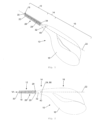
- the casing 28 always has grooves that are straight and perpendicular to the longitudinal direction and define support points 38 and that are at least approximately semicircular in cross-section, centered between each two adjacent bristle planes 36, wherein these support points 38 are arranged offset by 90° from space to space between each two bristle planes 36 in a direction of rotation.
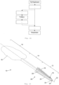
- the free ends of the bristles 20 lie on the lateral surface of an imaginary cone which widens (slightly) from the free end of the bristle field 26 in the direction of the neck section 14 and whose axis coincides with the longitudinal axis 22.
- bristle support stem 18 cylindrically, in particular circularly cylindrically, and/or to arrange the free ends of the bristles 20 in the shell of an imaginary circular cylinder concentric with the longitudinal axis 22, or, as is the case in connection with the Figures 15 to 18 shown, in the lateral surfaces of two oppositely directed cones. Other shapes are also possible.
- the casing 28 continuously merges into the neck casing 32 in the neck section 14, where the external cross section continuously increases from the neck section 14 towards the handle section 16. Furthermore, the casing 28 continuously merges into the cap-like extension 30 in the free end region of the interdental brush 10.
- the neck casing 32 has a passage 40 running at right angles to the longitudinal direction 22, which in the present case is circular-cylindrical and through which the support core 24 runs in the middle. This can be seen from the outside.
- the handle-side end of the support core 24 is not in the passage 40, but an end section of the support core 24 extends from the passage 40 in the direction towards the handle section 16 into the plastic from which the handle 16', the neck casing 32, the casing 28 with the extension 30 and the bristles 20 are made; this is shown in particular Figure 11 .
- the handle section 16 or the handle 16' is approximately the size of a fingertip, so that it can be easily held by the thumb and index finger.
- the handle section 16 or handle 16' can be given any other shape, in particular it can be made longer.
- FIGS 12 to 14 show a highly simplified embodiment of an injection molding tool 42 for producing the Figures 1 to 11 shown interdental brush 10.
- the injection molding tool 42 has a first tool part 44 for producing the bristle field section 12 and the neck section 14 and a second tool part 46 for producing the handle section 16.
- the first tool part 44 is provided with six bristle field tool parts 48, which in the closed state delimit a bristle field cavity 50 for producing the casing 28, the bristles 20 and the cap-like extension 30.
- a bristle field cavity 50 for producing the casing 28, the bristles 20 and the cap-like extension 30.
- the first tool part 44 is assigned two bar-like neck tool parts 56 which - in the closed state - delimit a neck cavity 58.
- the neck cavity 58 has a first neck cavity opening 60 on the side facing the bristle field cavity 50, which - in the closed state of the injection molding tool 42 - is arranged at the bristle field cavity opening 54 and is aligned with it; the neck tool parts 56 rest against the front side 52.
- the neck cavity 58 also has a second neck cavity opening 62 on the side facing away from the bristle field cavity 50 and facing the second tool part 46.
- each of the neck tool parts 56 is assigned a clamping punch 64.
- the clamping punches 64 are located radially opposite one another with respect to the longitudinal direction 22, which is defined by the bristle field cavity 50, and are movable along a straight line that runs at right angles to the longitudinal axis 22 and intersects it, from a rest position, into which they are opposed to each other, towards each other in a Figure 13 shown clamping position; this mobility is indicated by double arrows.
- the clamping stamps 64 together form a fixing element 64' for fixing the support core 24.
- the second tool part 46 has two handle tool parts 66, which form a handle cavity 68 when closed.
- the Figures 12 and 13 only one of the handle tool parts 66 is shown.
- the handle cavity 68 has a handle cavity opening 70 on a side facing the neck cavity 58, which - in the closed state of the injection molding tool - is arranged adjacent to the second neck cavity opening 62 and is aligned with it.
- the bristle field cavity 50, the neck cavity 58 and the handle cavity 68 together form an injection cavity 72.
- the bristle field cavity 50 is designed to correspond to the bristle field section 12 of the interdental brush 10
- the neck cavity 58 is designed to correspond to the neck section 14 of the interdental brush 10
- the handle cavity 68 is designed to correspond to the handle section 16 of the interdental brush 10.
- the dimensions of these cavities 50, 58, 68 are therefore also evident from the dimensions of the interdental brush 10 given in the introduction.
- the shapes of the cavities 50, 58 and 68 result from the interdental brush 10 shown in the figures.
- the plastic If the plastic is injected into the handle cavity 68, it flows through the neck cavity 58 into the bristle field cavity 50 without the support core 24 being able to be displaced in the longitudinal direction 22.
- Support elements 74 are shown, which are formed on bristle field tool parts 48 and correspond in opposite directions to the support points 38 described in connection with the description of the interdental brush 10.
- the support elements 74 protrude in the direction towards the interior of the bristle field cavity 50 and thus form the support points 38.
- the bristle field cavity 50 in the closed state of the injection molding tool 42, continuously merges into the neck cavity 58 and this continuously merges into the handle cavity 68, thus forming the injection cavity 72. It is of course conceivable to form steps, grooves or grooves at these transition points.
- the parting planes 76 of the bristle field tool parts 48 coincide with the longitudinal center planes 78 of the bristle rows 34.
- Figure 14 the bristles 20 arranged in one of the bristle planes 36, which are manufactured integrally with the casing 28 of the supporting core 24 by injection molding.
- the bristle field tool parts 48 are transferred in the radial direction relative to the longitudinal direction 22 into the closed state of the first tool part 44, after which they form the bristle field cavity 54, which has the bristle field cavity opening 54 on the front side 52.
- the support core 24 (arranged in the longitudinal direction) is then introduced in the longitudinal direction 22 through the bristle field cavity opening 54 into the bristle field cavity 50 and is then held in place by means of the clamping stamps 64.
- the support core 24 is first inserted into the neck tool part 56 and clamped and then introduced into the bristle field cavity 50 by moving the neck tool part 56 to the front side 52 of the bristle field tool parts 48, or the neck tool part 56 is moved to the bristle field cavity 50, the support core 24 is moved through the neck tool part 56 into the bristle field cavity 50 and then clamped.
- the plastic is introduced into the bristle field cavity 50 through the bristle field cavity opening 54.
- the support core 24 is held centrally in the bristle field cavity 50 by means of the support elements 74, which are distributed in the circumferential direction and in the longitudinal direction 22.
- the clamping dies 64 are assigned to the neck tool parts 56, which - in the closed state - delimit the neck cavity 58 connected to the bristle field cavity 50.
- the neck casing 32 is thus injected simultaneously and integrally with the casing 28 and the bristles 20.
- the clamping dies 64 are surrounded by the plastic and the passage 40 is formed in the neck jacket 32.
- a handle 16' of the interdental brush 10 is also formed.
- the first tool part 44 with the support core 24 introduced into the bristle field cavity 50 which is held in place by means of the clamping stamp 64, is brought to the second tool part 46 so that the second neck cavity opening 62 comes to lie at the handle cavity opening 70.
- the handle tool parts 66 are in the closed position and the handle cavity 68 is thus closed, the plastic is injected into it, which also reaches the bristle field cavity 50 through the neck cavity 58.
- the handle cavity 68 is opened by lifting the handle tool parts 66 away from each other. Then the handle 16' is removed from the area of the handle cavity 68 by moving the first tool part 44 and the second tool part 46 away from each other. After moving the clamping punch 64 from the clamping position in the radial direction outside the neck cavity 58 and opening the neck cavity 58 by moving the neck tool parts 56 away from each other and opening the bristle field cavity 50 by moving the bristle field tool parts 48 away from each other in the radial direction, the interdental brush 10 is completely demolded.
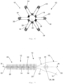
- FIGS. 15 to 18 show in perspective the first tool part 44 for producing interdental brushes, as shown in the other figures and described above.
- the cap-like extension 30 is formed in a separate part of the first tool part 44 - a cap tool part 80. This tool part would be in Fig. 15 and 16 visible, but is not shown for clarity.
- All bristles 20 are again arranged in six bristle rows 34 that are evenly distributed in the circumferential direction, and all bristles 20 are located in bristle planes 36 that are arranged at a constant distance from one another in the longitudinal direction 22. In each bristle plane 36 there is one bristle 20 of each bristle row 34. However, the free ends of the bristles 20 are no longer located on a single conical surface, but rather they end in two oppositely directed conical surfaces, which start with their smaller diameter from the axial ends of the bristle field 26 and meet at least approximately in the middle.
- dovetail-like guide slots 96 for the bristle field tool parts 48 are shown.
- the associated radial guides 84 are formed on a support body 86, the structure of which also Figures 17 and 18 can be removed.
- the support core 24 can be fed into the process as a part that is already in the correct length (for example a cut part) or as an endless part. In the second case, it is necessary to cut the support core 24 to the correct length during the process. It is also possible to form the support core 24 from a plastic material, for example in a separate or integrated injection molding process, so that an interdental brush could be made entirely from plastic.
- the first tool part 44 with the support core 24 inserted and held therein is moved into a third position C, in which the first tool part 44 is located near the second tool part 46.
- the handle cavity 68 is closed by moving the handle tool parts 66 towards each other.
- the first tool part 44 and the second tool part 46 are then moved towards each other and brought into position so that the handle cavity 68 together with the neck cavity 58 and the bristle field cavity 50 including the cap cavity 82 form the injection cavity 72.
- the plastic is then injected into the handle cavity 68, whereby the handle 16' is formed in the handle cavity 68, the neck jacket 32 in the neck cavity 58, the jacket 28 in the bristle field cavity 58 and the bristles 20 and the extension 30 in the cap cavity 82.
- the handle cavity 68 is opened by moving the handle tool parts 66 away from each other. This demolds the handle 16'. The first tool part 44 and the second tool part 46 are then moved away from each other. The first tool part 44 is then rotated to a fourth position D.
- this position D it is possible to inject a second component, for example made of a hard or soft component, onto the already manufactured handle 16'. If this is desired, a third tool part of the injection molding tool 42 is located in this fourth position D, which can be designed in the same way as the second tool part 46, but only the cavities next to the receptacle for the already manufactured handle 16' are designed for injecting the further component.
- a second component for example made of a hard or soft component
- the already produced handle 16' protrudes over the neck tool parts 56 and enters the relevant cavity in the fourth position D.
- the tool parts are moved together, the cavity is closed and then the second component is injected.
- the further handle cavity is opened and then the first tool part 44 is brought back into the first position, position A.
- the bristle field tool parts 48 are moved into the open state, whereby the bristle field section 12 and the handle section 16 of the interdental brush 10 are exposed.
- the interdental brush 10 is removed from the bristle field cavity 50.
- the neck tool parts 56 and the clamping dies 64 or the fixing elements 64' are then moved away from one another and the clamping dies 64 are moved into their rest position beforehand, simultaneously or afterwards.
- the interdental brushes 10 are free and can be removed from the injection molding tool 42, for example by means of a gripper (for example on a robot).
- the gripper holds the interdental brushes 10 when the neck tool parts 56 and the clamping punch 64 are opened.
- the Figure 20 The embodiment shown with four first tool parts 44 thus has the advantage of large production capacity, whereby while the first component of an interdental brush 10 is being injected, actions are carried out in the other positions.
- the fourth position D can be omitted, as shown in the Figure 21 is shown with a dashed line 126.
- the injection molding tool 42 advantageously has three first tool parts 44, which are rotated from position to position preferably by 120° each about the axis of rotation 124.
- the opening and product removal can be grouped and separated from the closing and merging of the tool parts.
- the injection molding tool 42 preferably has three first tool parts 44.
- the respective first tool parts 44 are arranged in the manner of the blades of a helicopter rotor, evenly distributed in the circumferential direction to the axis of rotation 124 and fastened to a central rotating part.
- Figure 22 It shows how the injection molding process and the other manufacturing steps are integrated into the overall manufacturing process when a so-called inline solution is used in the manufacturing process, ie the manufacturing steps are directly linked to one another.
- the advantages that this manufacturing method brings are obvious. For example, they are of an economic nature, no intermediate storage is necessary, and damage to the bristle field can be virtually ruled out.
- the injected interdental brushes 10 it is possible to rework the injected interdental brushes 10 in several steps and then package them directly. It is also possible to provide a buffer between the several processing steps. The buffer serves to cushion fluctuations in performance between the previous and subsequent process steps.
- the injected interdental brushes 10 can be provided with a label in a next step after injection molding, for example by embossing or printing.
- the post-processing can also affect the bristle field, for example the interdental brush 10 can undergo a curvature of the bristle support stem 18.
- the treatment of the bristle field 26 with substances, for example dental solutions, toothpastes or disinfectants, is also possible.
- the effect of heat on the bristle field 26 is also possible, as is a twisting of the bristle field 26 so that it takes on a torsional shape.
- processing operations can be carried out before or after buffering or directly before packaging the interdental brushes 10.
- the product is manufactured completely in the injection mold and is a "stand-alone" product
- the complete handle 16' instead of the complete handle 16', it is possible to design an interface geometry that fits onto an oppositely shaped part of a handle.
- the brush part is replaceable and is clicked into the handle or removably attached in another way.
- interdental brush it is also possible to design the interdental brush as identically as possible to an existing twisted brush, for example by making a handle out of plastic using an injection molding process. This means that existing twisted brushes without a brush handle can be replaced 1:1. This is used, for example, in handles into which simple twisted brushes can be inserted, with the twisted brushes being held/clamped by bending the extension of the bristle support stem.
- the co-injection process for the production of the interdental brushes mentioned above. This would mean that two Components are injected. Specifically, a first component is injected, but this does not completely fill the cavity. After partial hardening, a second material component is injected through the same injection point so that this component either displaces the existing partial component and takes up this space inside the existing component, or the additional component breaks through the existing component. This makes it possible to produce a two-component part in a single injection molding cavity. In this way, for example, the handle and bristles can be different colors or different materials can be used for the handle and bristles.
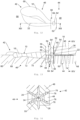
- FIG. 23 to 29 a variant of an interdental brush 10 is shown, in which the supporting core 24 is also made of a plastic by injection molding.
- the interdental brush 10 shown has a bristle field section 12 with a bristle field 26, a neck section 14 with a neck element 32 and a handle section 16 with a handle 16'.
- a bristle support stem 18, from which the bristles 20 protrude, also extends in this variant in a straight line over the entire length of the bristle field section 12 and defines a longitudinal direction 22; the dot-dash line indicating the longitudinal direction 22 in turn defines the longitudinal axis.
- the handle 16', the neck element 32 and the support core 24 are integrally injection-molded from a plastic.
- the support core 24, which adjoins the neck element 32 on the side facing away from the handle 16', has a smaller diameter than the neck element 32; the support core 24 preferably tapers with increasing distance from the neck 32.
- a casing 28 is injection-molded around the support core 24, which encloses the free end of the support core 24 facing away from the neck section 14 with a cap-like extension 30.
- the plastic component of the casing 28 covers a small part of the surface on the handle 16', while on the back of the interdental brush 10 on the neck element 14 it covers a significant part of the surface of one side before finally completely covering the surface in the bristle field section 26 (cf. Figure 25 ).
- a twisted brush is produced in a first step, which has twisted bristles at its front end and is equipped with twisted wire at its rear part. This part is placed in the injection molding cavity, clamped and also clamped in front of the area of the twisted bristles. The twisted wire is then overmolded and provided with injected bristles 20.
- the injection point 51" of the second component is located at the front end of the handle 16' facing the neck element 32.
- the second plastic component is injection-molded onto the front end of the handle 16' facing the neck element 32, wherein the second plastic component covers a small part of the surface on the handle 16', while it covers a substantial part of the surface on the back side of the neck element 32 and the surface of the support core 24 completely, or with the exception of a lower side (cf. Fig. 29 ), covered.
- a brush or interdental brush 10 according to the invention is shown, which in turn has a handle 16', from which the neck element 32 and the support core (here covered by the layer/sheathing 28) extend.
- three converging rows of bristles 34 are arranged on the upper side of the bristle stem 18, which, together with the two rows of bristles 34 projecting essentially horizontally from the support core (or bristle stem 18), define the bristle field 26.
- the bristles 20 decrease in length in the direction of the end of the bristle stem 18 facing away from the neck element 32. As is particularly evident in Fig. 34 As can be seen, the two rows of bristles 34, which protrude substantially horizontally from the support core, are arranged in a plane below the longitudinal axis 22 of the support core 24.
- the handle 16' of the brush is in the present case flat.
- the cap-like extension 30 of the layer/sheathing 28 in turn encloses the free end of the support core facing away from the neck element 32.
- the injection point 51" for the second plastic component is located either at the free end of the Support core or at the end of the support core facing the neck element 32 (ie in the bristle field cavity opening). No second plastic component is applied to the handle 16' and the neck element 32 of the individual brushes. In this embodiment, a cold runner system is regularly used.
- the injection point 51" is preferably located at the free end of the support core.
- two rows of bristles 34 are arranged on the upper side of the support core 24 or bristle stem 18, which run together in the direction of the end of the bristle stem 18 facing away from the neck element 32 (which, like the support core, tapers in this direction) and which, as in Figure 41 illustrated, protrude outwards inclined (ie not essentially vertically but also not radially) from the upper side of the support core 24.
- two rows of bristles 34 protruding essentially horizontally from the support core 24 or from the bristle stem 18 are again provided.
- the cap-like extension 30 of the layer/sheathing 28 also encloses the free end of the support core or the bristle stem 18 facing away from the neck element 32.
- the second Plastic component is injection-molded onto the rear end of the handle 16' facing away from the neck element 32, wherein the second plastic component on the handle 16' covers a large part of the surface both at the front and the back, while on the back it is attached to the neck element 32 (cf. Figure 39 ) covers a substantial part of the surface and completely covers the surface of the support core 24.
- the handle 16' of the brush has a trough-shaped recess 17 on the front and back for better holding, as shown in Fig. 40
- the second material component is guided in an elongated recess 19 of the neck element 32. Since the injection point 51" is located at the rear end of the handle 16', the second plastic component flows from there through the trough-shaped recess of the handle 17 and the elongated recess 19 of the neck element 32 to the support core, where it finally forms (in the corresponding bristle field cavity) the layer or sheath 28 with the bristles 20.
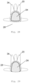
- Figure 38 one can see the support points 130 at which the support elements 74 of the bristle field cavity 50 (cf. analog Figure 13 ) and prevent the support core 24 from being moved in the radial direction and possibly closing the openings for the individual bristles 20 to be formed.
- a hot runner system is usually provided so that the second plastic component does not solidify prematurely on its relatively long flow path.
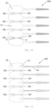
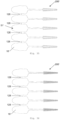
- the present handle shape of the brushes is essentially rectangular and has a lateral indentation 131 on each side. This is due to the fact that the individual brushes of the product group 200" are connected via two material bridges 128, 128', wherein the material bridges 128 are formed from the first plastic component and the material bridges 128' are formed from the second plastic component.
- the material bridges 128 from the first plastic component are each arranged in the rear area of the handle 16' and the material bridges 128' from the second plastic component are each arranged in the front area of the handle 16'. With this design, there does not have to be an injection point for the second plastic component on each brush.
- the handles 16' (including the neck element and support core) initially injection-molded from the first plastic component are located close to one another.
- the handles 16' have transitions 132 on the top and back in the area of the second material bridge 128' (to be injection-molded later), over which the second plastic component can be distributed. This means that an injection point for the second plastic component does not have to be provided on every product or every brush.
- This product group 200" also preferably consists of five brushes each.
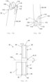
- an interdental brush which has a notch 134 at the rear end of the handle 16' for attaching the brush to a corresponding holder 140 or a cup or a glass.
- it is an interdental brush with an overmolded wire or support core 24, which protrudes from the neck element 32 and carries a bristle field 26.
- the material of the at least one plastic component for the handle 16' and the neck element 32 can be selected such that the two lateral flanks 136 (or clamping arms) of the handle 16' surrounding the notch 134 are designed to be resilient and can thus be applied to the holder 140, the glass or the cup or the like in a form-fitting and force-fitting manner.
- the handle 16' or the handle 16' and the neck element 32 can also be injection-molded from two (or more) different plastic components.
- the notch 134 is encased with a border 135 made of a second or further plastic component, which regularly represents a soft component. This can further improve the grip of the brush on the respective holder 140.
- the border 135 is H-shaped, which can be advantageous for handling.
- the lower ends of the lateral flanks 136 are preferably completely surrounded by the soft component. As in the side view according to Figure 45 As can be seen, the lateral flanks 136 taper towards their lower end.
- Such a notch 134 and border 135 can of course also be used in an interdental brush with a plastic injection-molded core, as shown in the Figures 23-43 illustrated (as well as in corresponding product groups).
- the injection point for the first plastic component 51' is located in the embodiments according to the Figures 23 to 46 preferably in the handle area. Depending on the design, one or more injection points per product or product group are conceivable. Preferably, one injection point will be provided, with the plastic material being distributed in the individual product and across the material bridges.
- the respective brushes according to the Figures 23 to 46 can be injected in the parting line of a two-part injection molding tool and easily demolded, which enables particularly cost-effective and efficient production.
- the injection molding tool for these designs also generally does not require any neck tool parts or clamping dies.
- design variants shown in this document are examples. Within the scope of the present invention, the individual characteristics and elements of these design variants can easily be combined with other design variants.
Landscapes
- Engineering & Computer Science (AREA)
- Manufacturing & Machinery (AREA)
- Mechanical Engineering (AREA)
- Brushes (AREA)
Applications Claiming Priority (6)
| Application Number | Priority Date | Filing Date | Title |
|---|---|---|---|
| EP12004914 | 2012-07-02 | ||
| PCT/EP2013/001412 WO2014005659A1 (fr) | 2012-07-02 | 2013-05-14 | Procédé de fabrication de brosses, notamment de brossettes interdentaires, et brosses, notamment brossettes interdentaires, et groupe de produits composés de plusieurs brosses |
| EP22185822.8A EP4098147B1 (fr) | 2012-07-02 | 2013-05-14 | Brosse interdentaire |
| EP20176973.4A EP3729997B1 (fr) | 2012-07-02 | 2013-05-14 | Procede de fabrication d'une brosse interdentaire |
| EP15179848.5A EP2974619B1 (fr) | 2012-07-02 | 2013-05-14 | Brosse interdentaire, procede de fabrication d'une brosse interdentaire et groupe de produit a partir de plusieurs brosses interdentaires |
| EP13725569.1A EP2866610A1 (fr) | 2012-07-02 | 2013-05-14 | Procédé de fabrication de brosses, notamment de brossettes interdentaires, et brosses, notamment brossettes interdentaires, et groupe de produits composés de plusieurs brosses |
Related Parent Applications (5)
| Application Number | Title | Priority Date | Filing Date |
|---|---|---|---|
| EP15179848.5A Division EP2974619B1 (fr) | 2012-07-02 | 2013-05-14 | Brosse interdentaire, procede de fabrication d'une brosse interdentaire et groupe de produit a partir de plusieurs brosses interdentaires |
| EP22185822.8A Division-Into EP4098147B1 (fr) | 2012-07-02 | 2013-05-14 | Brosse interdentaire |
| EP22185822.8A Division EP4098147B1 (fr) | 2012-07-02 | 2013-05-14 | Brosse interdentaire |
| EP20176973.4A Division EP3729997B1 (fr) | 2012-07-02 | 2013-05-14 | Procede de fabrication d'une brosse interdentaire |
| EP13725569.1A Division EP2866610A1 (fr) | 2012-07-02 | 2013-05-14 | Procédé de fabrication de brosses, notamment de brossettes interdentaires, et brosses, notamment brossettes interdentaires, et groupe de produits composés de plusieurs brosses |
Publications (2)
| Publication Number | Publication Date |
|---|---|
| EP4483751A2 true EP4483751A2 (fr) | 2025-01-01 |
| EP4483751A3 EP4483751A3 (fr) | 2025-02-26 |
Family
ID=48536782
Family Applications (5)
| Application Number | Title | Priority Date | Filing Date |
|---|---|---|---|
| EP22185822.8A Active EP4098147B1 (fr) | 2012-07-02 | 2013-05-14 | Brosse interdentaire |
| EP24212606.8A Pending EP4483751A3 (fr) | 2012-07-02 | 2013-05-14 | Brosse interdentaire |
| EP13725569.1A Ceased EP2866610A1 (fr) | 2012-07-02 | 2013-05-14 | Procédé de fabrication de brosses, notamment de brossettes interdentaires, et brosses, notamment brossettes interdentaires, et groupe de produits composés de plusieurs brosses |
| EP20176973.4A Active EP3729997B1 (fr) | 2012-07-02 | 2013-05-14 | Procede de fabrication d'une brosse interdentaire |
| EP15179848.5A Active EP2974619B1 (fr) | 2012-07-02 | 2013-05-14 | Brosse interdentaire, procede de fabrication d'une brosse interdentaire et groupe de produit a partir de plusieurs brosses interdentaires |
Family Applications Before (1)
| Application Number | Title | Priority Date | Filing Date |
|---|---|---|---|
| EP22185822.8A Active EP4098147B1 (fr) | 2012-07-02 | 2013-05-14 | Brosse interdentaire |
Family Applications After (3)
| Application Number | Title | Priority Date | Filing Date |
|---|---|---|---|
| EP13725569.1A Ceased EP2866610A1 (fr) | 2012-07-02 | 2013-05-14 | Procédé de fabrication de brosses, notamment de brossettes interdentaires, et brosses, notamment brossettes interdentaires, et groupe de produits composés de plusieurs brosses |
| EP20176973.4A Active EP3729997B1 (fr) | 2012-07-02 | 2013-05-14 | Procede de fabrication d'une brosse interdentaire |
| EP15179848.5A Active EP2974619B1 (fr) | 2012-07-02 | 2013-05-14 | Brosse interdentaire, procede de fabrication d'une brosse interdentaire et groupe de produit a partir de plusieurs brosses interdentaires |
Country Status (3)
| Country | Link |
|---|---|
| US (2) | US10299577B2 (fr) |
| EP (5) | EP4098147B1 (fr) |
| WO (1) | WO2014005659A1 (fr) |
Families Citing this family (41)
| Publication number | Priority date | Publication date | Assignee | Title |
|---|---|---|---|---|
| EP4098147B1 (fr) | 2012-07-02 | 2024-12-18 | Trisa Holding AG | Brosse interdentaire |
| ITTO20130060U1 (it) * | 2013-04-11 | 2014-10-12 | Spada Forniture Di Spada Giuseppe | Dispositivo di pulizia dentale. |
| USD757440S1 (en) * | 2013-06-15 | 2016-05-31 | Interbros Gmbh | Interdental brush |
| DE14158195T1 (de) | 2014-03-06 | 2015-03-12 | Tepe Munhygienprodukter Ab | Interdentalreiniger |
| USD764103S1 (en) | 2014-10-27 | 2016-08-16 | Tepe Munhygienprodukter Ab | Interdental cleaner |
| USD764104S1 (en) | 2014-10-27 | 2016-08-16 | Tepe Munhygienprodukter Ab | Interdental cleaner |
| WO2016076373A1 (fr) * | 2014-11-11 | 2016-05-19 | サンスター スイス エスエー | Procédé de fabrication d'un outil de nettoyage interdentaire |
| CN107106273A (zh) * | 2014-11-11 | 2017-08-29 | 太阳星光齿磨公司 | 牙缝清洁工具 |
| DE102014017257A1 (de) * | 2014-11-24 | 2016-05-25 | Interbros Gmbh | Verfahren und Vorrichtung zur Herstellung eines Interdentalreinigers |
| JP5977382B2 (ja) | 2015-01-16 | 2016-08-24 | 小林製薬株式会社 | 歯間清掃具 |
| USD767900S1 (en) * | 2015-03-03 | 2016-10-04 | LeedTech Resources Company, LLC | Interdental brush |
| USD756125S1 (en) * | 2015-03-20 | 2016-05-17 | Welter's Co., Ltd. | Toothpick brush |
| JP6596885B2 (ja) * | 2015-03-31 | 2019-10-30 | 東レ・モノフィラメント株式会社 | 歯間清掃具用線材 |
| EP3928659B1 (fr) | 2015-05-04 | 2023-07-26 | Trisa Holding AG | Appareil électrique de soins corporels |
| JP6547830B2 (ja) * | 2015-06-08 | 2019-07-24 | サンスター スイス エスエー | 歯間清掃具 |
| FR3042391B1 (fr) * | 2015-10-19 | 2020-03-20 | L'oreal | Applicateur de produit cosmetique |
| JP6925776B2 (ja) * | 2015-12-18 | 2021-08-25 | 小林製薬株式会社 | 歯間清掃具 |
| DE102016005012A1 (de) * | 2016-04-26 | 2017-10-26 | Interbros Gmbh | Interdentalreiniger |
| JP1600693S (fr) * | 2016-07-14 | 2018-03-26 | ||
| CN107053609B (zh) * | 2017-02-23 | 2019-05-03 | 汕头市金昱塑胶有限公司 | 一种带齿缝刷牙签模具及其制造方法 |
| US10681974B2 (en) * | 2017-04-04 | 2020-06-16 | Ranir, Llc | Interdental toothbrush |
| USD838909S1 (en) | 2017-04-04 | 2019-01-22 | Dentek Oral Care, Inc. | Interdental pick |
| USD838910S1 (en) | 2017-04-04 | 2019-01-22 | Dentek Oral Care, Inc. | Interdental pick set with frame |
| WO2019057516A1 (fr) * | 2017-09-19 | 2019-03-28 | Trisa Holding Ag | Dispositif applicateur |
| DE102017010561A1 (de) * | 2017-11-15 | 2019-05-16 | Interbros Gmbh | Interdentalreiniger |
| US10674808B2 (en) | 2018-03-23 | 2020-06-09 | Colgate-Palmolive Company | Oral care implement and method of forming the same |
| US11206918B2 (en) | 2018-03-25 | 2021-12-28 | Parallel Capture Holdings Inc. | Interdental brush with nylon yarn strands |
| JP7212457B2 (ja) * | 2018-04-27 | 2023-01-25 | 小林製薬株式会社 | 歯間清掃具 |
| US20200046475A1 (en) * | 2018-08-13 | 2020-02-13 | Prajeshkumar Y. Desai | Kite Gum Brush |
| USD910315S1 (en) * | 2018-08-14 | 2021-02-16 | SangGeun Lee | Interdental brush |
| JP7188077B2 (ja) * | 2018-12-28 | 2022-12-13 | サンスター株式会社 | 歯間清掃具 |
| JP7417353B2 (ja) | 2018-12-28 | 2024-01-18 | 小林製薬株式会社 | 歯間清掃具の製造方法 |
| JP7652528B2 (ja) * | 2018-12-28 | 2025-03-27 | 小林製薬株式会社 | 歯間清掃具 |
| JP2020103851A (ja) | 2018-12-28 | 2020-07-09 | 小林製薬株式会社 | 歯間清掃具 |
| EP3964166A1 (fr) * | 2020-09-03 | 2022-03-09 | Trisa Holding AG | Produit de soins du corps |
| CN111941737B (zh) * | 2020-09-18 | 2022-11-15 | 江苏常熟汽饰集团股份有限公司 | 表面嵌入玻璃纤维复合片材的注塑产品局部加强注塑方法 |
| DE102020128848A1 (de) | 2020-11-03 | 2022-05-05 | Interbros Gmbh | Verfahren und Vorrichtung zur Aufbringung einer Beschichtung auf einen Interdentalreiniger und Interdentalreiniger mit einer Beschichtung |
| US12161219B2 (en) | 2021-02-03 | 2024-12-10 | Judson Smith | Cleaning bristle brushes and cleaning systems using same |
| DE102021113332A1 (de) * | 2021-05-21 | 2022-11-24 | Interbros Gmbh | Interdental-Reiniger |
| CN115804496A (zh) | 2021-09-14 | 2023-03-17 | 株式会社Lg生活健康 | 牙间刷及其制造方法 |
| CN113977869A (zh) * | 2021-10-28 | 2022-01-28 | 扬州美星口腔护理用品有限公司 | 一种胶毛齿间刷的注胶模具 |
Citations (4)
| Publication number | Priority date | Publication date | Assignee | Title |
|---|---|---|---|---|
| US3698405A (en) | 1970-04-08 | 1972-10-17 | Richard M Walker | Orthodontal toothpick |
| WO1998016169A1 (fr) | 1996-10-15 | 1998-04-23 | Coronet-Werke Gmbh | Nettoyeur interdentaire et mode de fabrication |
| EP1258227A2 (fr) | 2001-05-16 | 2002-11-20 | Roeko GmbH + Co. KG | Instrument de nettoyage pour racines dentaires |
| WO2008146968A1 (fr) | 2007-05-28 | 2008-12-04 | Amorepacific Corporation | Procédé de fabrication d'une brosse à mascara du type à insertion renforcée |
Family Cites Families (61)
| Publication number | Priority date | Publication date | Assignee | Title |
|---|---|---|---|---|
| US2225331A (en) | 1938-10-18 | 1940-12-17 | Pauline Campbell | Rubber bristled toothbursh |
| CH296417A (de) * | 1952-04-18 | 1954-02-15 | Bolta Werk Gmbh | Verfahren zur Herstellung von Massagebürsten aus thermoplastischen Werkstoffen. |
| DE941364C (de) | 1954-06-03 | 1956-04-12 | Edwin Grether | Verfahren zum Herstellen von Buersten, deren Buerstenkoerper und Borsten aus einem Stueck bestehen, das im Spritzverfahren hergestellt ist, und Buerste nach diesem Verfahren |
| FR1393210A (fr) * | 1961-08-11 | 1965-03-26 | Celluloid Sa | Nouvelle brosse |
| SE310646B (fr) | 1964-10-30 | 1969-05-12 | A Poppelman | |
| EP0038524B1 (fr) * | 1980-04-19 | 1985-08-07 | Georg Karl Geka-Brush Gmbh | Brosse à mascara et procédé de fabrication |
| US4635313A (en) | 1983-11-16 | 1987-01-13 | North American Philips Corporation | Brush with self retaining bristles |
| US5497526A (en) | 1986-12-04 | 1996-03-12 | Oral Logic Inc. | Tooth brushing device |
| JP2815542B2 (ja) | 1994-08-31 | 1998-10-27 | 三菱電機ホーム機器株式会社 | 多孔質構造体を用いた吸音機構 |
| USD416685S (en) * | 1995-03-28 | 1999-11-23 | Gillette Canada Inc. | Toothbrush handle |
| US5987688A (en) | 1995-11-09 | 1999-11-23 | Gillette Canada Inc. | Gum-massaging oral brush |
| US6996870B2 (en) | 1995-12-29 | 2006-02-14 | Colgate-Palmolive Company | Contouring toothbrush head |
| US5775346A (en) * | 1996-02-14 | 1998-07-07 | Advanced Implant Technologies Inc. | Interproximal dental appliances |
| US6514445B1 (en) | 1996-12-24 | 2003-02-04 | The Procter & Gamble Company | Brush making |
| JP2001511722A (ja) * | 1997-02-14 | 2001-08-14 | スミスクライン・ビーチャム・コンシューマー・ヘルスケア・ゲゼルシャフト・ミット・ベシュレンクテル・ハフツング | 2種の成分から製品を作成する射出成形法および装置 |
| JP3002668B1 (ja) * | 1998-07-14 | 2000-01-24 | 株式会社広栄社 | ブラシ楊枝 |
| JP3824041B2 (ja) * | 1998-12-04 | 2006-09-20 | 株式会社三▲しゅう▼プレシジョン | 歯間清掃具及びその製造方法 |
| US6292973B1 (en) * | 1999-04-29 | 2001-09-25 | Robert Moskovich | Toothbrush having controlled head movement |
| US6885812B2 (en) | 2003-03-06 | 2005-04-26 | Mks Instruments, Inc. | System and method for heating solid or vapor source vessels and flow paths |
| US6859969B2 (en) | 1999-06-11 | 2005-03-01 | James A. Gavney, Jr. | Multi-directional wiping elements and device using the same |
| DE10033256A1 (de) | 2000-07-10 | 2002-01-24 | Coronet Werke Gmbh | Verfahren und Vorrichtung zur Herstellung von Borstenwaren sowie Borstenware |
| JP4132744B2 (ja) | 2000-08-23 | 2008-08-13 | 花王株式会社 | ブラシの製造方法及び装置 |
| US20060230563A1 (en) | 2000-09-19 | 2006-10-19 | Gavney James A Jr | Oral care device with multi-structural contact elements |
| CN1251631C (zh) | 2000-10-02 | 2006-04-19 | 纳幕尔杜邦公司 | 清洁牙齿的低摩擦牙刷和方法 |
| DE10102219A1 (de) * | 2001-01-19 | 2002-07-25 | Beiersdorf Ag | Applikator für flüssige oder pastöse Medien, insbesondere dekorative kosmetika wie Mascara |
| US7143462B2 (en) | 2002-09-20 | 2006-12-05 | Colgate-Palmolive Company | Oral care implement |
| DE10201635A1 (de) | 2002-01-17 | 2003-07-31 | Coronet Werke Gmbh | Verfahren und Vorrichtung zur Herstellung von Borsten |
| DE10212701B4 (de) | 2002-03-21 | 2015-05-13 | Geka Gmbh | Borste, Verfahren und Vorrichtung zu ihrer Herstellung sowie Borstenware |
| DE10221869A1 (de) | 2002-05-15 | 2003-11-27 | Coronet Werke Gmbh | Verfahren zur Herstellung einer Borstenstruktur an einem Träger |
| DE10235642A1 (de) | 2002-08-02 | 2004-02-19 | Zahoransky Formenbau Gmbh | Verfahren und Vorrichtung zum Herstellen von Zahnbürsten |
| ES2398653T3 (es) | 2002-09-05 | 2013-03-20 | Colgate-Palmolive Company | Cepillo de dientes desechable |
| US7478959B2 (en) | 2002-09-05 | 2009-01-20 | Colgate-Palmolive Company | Oral care toothbrush |
| JP4236571B2 (ja) * | 2002-12-20 | 2009-03-11 | 花王株式会社 | 歯間清掃用具及びその成形方法 |
| KR100573898B1 (ko) | 2003-06-09 | 2006-04-26 | 권영준 | 칫솔의 제조방법 |
| EP1639913B1 (fr) | 2004-09-22 | 2011-11-23 | Trisa Holding AG | Brosse, notamment brosse à dents et procédé de fabrication |
| EP1752062A1 (fr) * | 2005-08-11 | 2007-02-14 | Geka Brush Gmbh | Applicateur pour un produit cosmétique, en particulier pour mascara ou une composition de coloration capillaire |
| US20090007357A1 (en) | 2007-05-07 | 2009-01-08 | The Gillette Company | Oral Hygiene Implements |
| FR2917276B1 (fr) * | 2007-06-15 | 2012-07-27 | Cinqpats | Dispositif et conditionnement de brossage et de peignage de precision, ainsi que procede et outillage d'obtention |
| PL2030524T3 (pl) | 2007-08-31 | 2011-04-29 | Geka Gmbh | Zgarniacz jednostki kosmetycznej |
| DE202007014474U1 (de) | 2007-10-16 | 2009-03-05 | Schwan-Stabilo Cosmetics Gmbh & Co. Kg | Aufgespritzte Applikatoren |
| FR2922420B1 (fr) | 2007-10-23 | 2011-04-01 | Oreal | Applicateur pour l'application d'un produit sur les cils ou les sourcils |
| WO2009072747A1 (fr) | 2007-12-06 | 2009-06-11 | Tae Yeon Kim | Brosse à dents et son procédé de fabrication |
| US20090230756A1 (en) * | 2008-03-12 | 2009-09-17 | Ranir, Llc | Interdental cleaning tool |
| DE102008016637A1 (de) | 2008-04-01 | 2009-10-08 | Firma G.B. Boucherie N.V. | Bürste, insbesondere für Haushalt oder industrielle Anwendungen |
| WO2010014623A1 (fr) * | 2008-07-29 | 2010-02-04 | Sunstar Americas, Inc. | Nettoyeurs inter-dentaires et leurs procédés de fabrication |
| FR2943898B3 (fr) * | 2009-04-07 | 2011-04-01 | Banat Firca Ve Plastik Sanayi Anonim Sirketi | Corps de brosse a dents a fente. |
| US20110041271A1 (en) * | 2009-08-19 | 2011-02-24 | Acumen Co., Ltd. | Interdental brush |
| TWI462709B (zh) * | 2010-03-31 | 2014-12-01 | Colgate Palmolive Co | 可快速釋放味道的口腔保健用具 |
| USD637817S1 (en) * | 2010-09-16 | 2011-05-17 | Betty Lou Smith | Toothbrush |
| EP4154762A3 (fr) | 2011-01-04 | 2023-09-20 | Trisa Holding AG | Brosse à dents pourvue de soies moulées par injection |
| JP2012152928A (ja) * | 2011-01-24 | 2012-08-16 | Japan Steel Works Ltd:The | 歯間ブラシの成形方法および成形装置 |
| JP2012159228A (ja) | 2011-01-31 | 2012-08-23 | Mitsubishi Electric Corp | ヒートポンプ給湯機の制御装置及び制御方法 |
| DE202011002793U1 (de) * | 2011-02-16 | 2012-06-12 | Geka Gmbh | Applikator mit rohrförmigem, umspritztem Kernelement |
| DE102011011323A1 (de) | 2011-02-16 | 2012-08-16 | Interbros Gmbh | Mund- oder Zahnreinigungsgerät |
| CA2829119A1 (fr) * | 2011-03-09 | 2012-09-13 | Colgate-Palmolive Company | Dispositif pour nettoyer entre les dents |
| EP2554353B1 (fr) | 2011-08-05 | 2017-06-07 | Trisa Holding AG | Procédé de fabrication d'une brosse à dents et brosse à dents |
| JP5929346B2 (ja) * | 2012-03-13 | 2016-06-01 | サンスター株式会社 | 歯間清掃具の製造方法 |
| JP6069311B2 (ja) | 2012-05-24 | 2017-02-01 | サンスター スイス エスエー | 歯間清掃具の製造方法及び歯間清掃具 |
| EP4098147B1 (fr) | 2012-07-02 | 2024-12-18 | Trisa Holding AG | Brosse interdentaire |
| DE102012015664A1 (de) | 2012-08-09 | 2014-02-13 | Interbros Gmbh | Interdental-Reiniger |
| DE102012025039B4 (de) | 2012-12-20 | 2015-02-19 | Zahoransky Formenbau Gmbh | Verfahren zur Herstellung von Spritzgießteilen in Zwei-Komponenten-Spritzgießtechnik sowie Spritzgießteil |
-
2013
- 2013-05-14 EP EP22185822.8A patent/EP4098147B1/fr active Active
- 2013-05-14 EP EP24212606.8A patent/EP4483751A3/fr active Pending
- 2013-05-14 EP EP13725569.1A patent/EP2866610A1/fr not_active Ceased
- 2013-05-14 EP EP20176973.4A patent/EP3729997B1/fr active Active
- 2013-05-14 EP EP15179848.5A patent/EP2974619B1/fr active Active
- 2013-05-14 US US14/410,536 patent/US10299577B2/en active Active
- 2013-05-14 WO PCT/EP2013/001412 patent/WO2014005659A1/fr not_active Ceased
-
2019
- 2019-04-26 US US16/396,044 patent/US11622617B2/en active Active
Patent Citations (4)
| Publication number | Priority date | Publication date | Assignee | Title |
|---|---|---|---|---|
| US3698405A (en) | 1970-04-08 | 1972-10-17 | Richard M Walker | Orthodontal toothpick |
| WO1998016169A1 (fr) | 1996-10-15 | 1998-04-23 | Coronet-Werke Gmbh | Nettoyeur interdentaire et mode de fabrication |
| EP1258227A2 (fr) | 2001-05-16 | 2002-11-20 | Roeko GmbH + Co. KG | Instrument de nettoyage pour racines dentaires |
| WO2008146968A1 (fr) | 2007-05-28 | 2008-12-04 | Amorepacific Corporation | Procédé de fabrication d'une brosse à mascara du type à insertion renforcée |
Also Published As
| Publication number | Publication date |
|---|---|
| WO2014005659A1 (fr) | 2014-01-09 |
| EP4098147B1 (fr) | 2024-12-18 |
| EP3729997A1 (fr) | 2020-10-28 |
| US20150335141A1 (en) | 2015-11-26 |
| EP2974619A3 (fr) | 2016-04-06 |
| US20190246778A1 (en) | 2019-08-15 |
| EP2974619A2 (fr) | 2016-01-20 |
| EP4098147A1 (fr) | 2022-12-07 |
| US10299577B2 (en) | 2019-05-28 |
| EP2866610A1 (fr) | 2015-05-06 |
| US11622617B2 (en) | 2023-04-11 |
| EP2974619B1 (fr) | 2020-07-08 |
| EP3729997B1 (fr) | 2022-08-24 |
| EP4483751A3 (fr) | 2025-02-26 |
Similar Documents
| Publication | Publication Date | Title |
|---|---|---|
| EP4098147B1 (fr) | Brosse interdentaire | |
| EP3539417B1 (fr) | Brosse à dents pourvue de soies moulées par injection | |
| EP2554353B1 (fr) | Procédé de fabrication d'une brosse à dents et brosse à dents | |
| EP2130454B1 (fr) | Procédé de fabrication de brosses à dents à poils non ancrés | |
| WO2021105202A2 (fr) | Produit d'hygiène bucco-dentaire | |
| WO2017182355A1 (fr) | Produit de type brosse et procédé de fabrication | |
| EP2632293B1 (fr) | Brosse et procédé pour fabriquer une brosse | |
| WO2001058306A1 (fr) | Procede de production d'un manche creux destine a un instrument de nettoyage des dents | |
| EP2682022A1 (fr) | Brosse ménagère ou brosse de soin corporel dotée de poils moulés par injection et outil de moulage par injection pour sa fabrication | |
| DE20303934U1 (de) | Vorrichtung zum Herstellen einer Bürste | |
| EP2200532B1 (fr) | Appareil de nettoyage des dents et procede de sa fabrication | |
| EP1494561B1 (fr) | Brosse a dents et procede de fabrication | |
| EP3833219B1 (fr) | Moyen d'hygiène buccale, en particulier brosse à dents | |
| EP4509013A1 (fr) | Produit de soins personnels, en particulier produit d'hygiène buccale |
Legal Events
| Date | Code | Title | Description |
|---|---|---|---|
| PUAI | Public reference made under article 153(3) epc to a published international application that has entered the european phase |
Free format text: ORIGINAL CODE: 0009012 |
|
| STAA | Information on the status of an ep patent application or granted ep patent |
Free format text: STATUS: THE APPLICATION HAS BEEN PUBLISHED |
|
| AC | Divisional application: reference to earlier application |
Ref document number: 2866610 Country of ref document: EP Kind code of ref document: P Ref document number: 2974619 Country of ref document: EP Kind code of ref document: P Ref document number: 3729997 Country of ref document: EP Kind code of ref document: P Ref document number: 4098147 Country of ref document: EP Kind code of ref document: P |
|
| AK | Designated contracting states |
Kind code of ref document: A2 Designated state(s): AL AT BE BG CH CY CZ DE DK EE ES FI FR GB GR HR HU IE IS IT LI LT LU LV MC MK MT NL NO PL PT RO RS SE SI SK SM TR |
|
| REG | Reference to a national code |
Ref country code: DE Ref legal event code: R079 Free format text: PREVIOUS MAIN CLASS: A46B0001000000 Ipc: A46B0003000000 |
|
| PUAL | Search report despatched |
Free format text: ORIGINAL CODE: 0009013 |
|
| AK | Designated contracting states |
Kind code of ref document: A3 Designated state(s): AL AT BE BG CH CY CZ DE DK EE ES FI FR GB GR HR HU IE IS IT LI LT LU LV MC MK MT NL NO PL PT RO RS SE SI SK SM TR |
|
| RIC1 | Information provided on ipc code assigned before grant |
Ipc: A46B 1/00 20060101ALI20250121BHEP Ipc: A46B 5/02 20060101ALI20250121BHEP Ipc: A46B 15/00 20060101ALI20250121BHEP Ipc: A46D 3/00 20060101ALI20250121BHEP Ipc: A46B 9/02 20060101ALI20250121BHEP Ipc: B29C 45/16 20060101ALI20250121BHEP Ipc: B29C 45/14 20060101ALI20250121BHEP Ipc: A46B 3/00 20060101AFI20250121BHEP |
|
| STAA | Information on the status of an ep patent application or granted ep patent |
Free format text: STATUS: REQUEST FOR EXAMINATION WAS MADE |
|
| 17P | Request for examination filed |
Effective date: 20250619 |