EP4478697A2 - Bildlesevorrichtung und bilderzeugungsvorrichtung - Google Patents
Bildlesevorrichtung und bilderzeugungsvorrichtung Download PDFInfo
- Publication number
- EP4478697A2 EP4478697A2 EP24203809.9A EP24203809A EP4478697A2 EP 4478697 A2 EP4478697 A2 EP 4478697A2 EP 24203809 A EP24203809 A EP 24203809A EP 4478697 A2 EP4478697 A2 EP 4478697A2
- Authority
- EP
- European Patent Office
- Prior art keywords
- reading unit
- sheet
- reading
- image
- conveying
- Prior art date
- Legal status (The legal status is an assumption and is not a legal conclusion. Google has not performed a legal analysis and makes no representation as to the accuracy of the status listed.)
- Granted
Links
Images











Classifications
-
- H—ELECTRICITY
- H04—ELECTRIC COMMUNICATION TECHNIQUE
- H04N—PICTORIAL COMMUNICATION, e.g. TELEVISION
- H04N1/00—Scanning, transmission or reproduction of documents or the like, e.g. facsimile transmission; Details thereof
- H04N1/00909—Cleaning arrangements or preventing or counter-acting contamination from dust or the like
-
- G—PHYSICS
- G03—PHOTOGRAPHY; CINEMATOGRAPHY; ANALOGOUS TECHNIQUES USING WAVES OTHER THAN OPTICAL WAVES; ELECTROGRAPHY; HOLOGRAPHY
- G03G—ELECTROGRAPHY; ELECTROPHOTOGRAPHY; MAGNETOGRAPHY
- G03G15/00—Apparatus for electrographic processes using a charge pattern
- G03G15/65—Apparatus which relate to the handling of copy material
- G03G15/6529—Transporting
-
- G—PHYSICS
- G03—PHOTOGRAPHY; CINEMATOGRAPHY; ANALOGOUS TECHNIQUES USING WAVES OTHER THAN OPTICAL WAVES; ELECTROGRAPHY; HOLOGRAPHY
- G03G—ELECTROGRAPHY; ELECTROPHOTOGRAPHY; MAGNETOGRAPHY
- G03G21/00—Arrangements not provided for by groups G03G13/00 - G03G19/00, e.g. cleaning, elimination of residual charge
- G03G21/16—Mechanical means for facilitating the maintenance of the apparatus, e.g. modular arrangements
- G03G21/1604—Arrangement or disposition of the entire apparatus
- G03G21/1623—Means to access the interior of the apparatus
- G03G21/1628—Clamshell type
-
- G—PHYSICS
- G03—PHOTOGRAPHY; CINEMATOGRAPHY; ANALOGOUS TECHNIQUES USING WAVES OTHER THAN OPTICAL WAVES; ELECTROGRAPHY; HOLOGRAPHY
- G03G—ELECTROGRAPHY; ELECTROPHOTOGRAPHY; MAGNETOGRAPHY
- G03G21/00—Arrangements not provided for by groups G03G13/00 - G03G19/00, e.g. cleaning, elimination of residual charge
- G03G21/16—Mechanical means for facilitating the maintenance of the apparatus, e.g. modular arrangements
- G03G21/1604—Arrangement or disposition of the entire apparatus
- G03G21/1623—Means to access the interior of the apparatus
- G03G21/1638—Means to access the interior of the apparatus directed to paper handling or jam treatment
-
- H—ELECTRICITY
- H04—ELECTRIC COMMUNICATION TECHNIQUE
- H04N—PICTORIAL COMMUNICATION, e.g. TELEVISION
- H04N1/00—Scanning, transmission or reproduction of documents or the like, e.g. facsimile transmission; Details thereof
- H04N1/00519—Constructional details not otherwise provided for, e.g. housings, covers
- H04N1/00543—Allowing easy access, e.g. for maintenance or in case of paper jam
-
- H—ELECTRICITY
- H04—ELECTRIC COMMUNICATION TECHNIQUE
- H04N—PICTORIAL COMMUNICATION, e.g. TELEVISION
- H04N1/00—Scanning, transmission or reproduction of documents or the like, e.g. facsimile transmission; Details thereof
- H04N1/00519—Constructional details not otherwise provided for, e.g. housings, covers
- H04N1/00551—Top covers or the like
-
- H—ELECTRICITY
- H04—ELECTRIC COMMUNICATION TECHNIQUE
- H04N—PICTORIAL COMMUNICATION, e.g. TELEVISION
- H04N1/00—Scanning, transmission or reproduction of documents or the like, e.g. facsimile transmission; Details thereof
- H04N1/00519—Constructional details not otherwise provided for, e.g. housings, covers
- H04N1/00557—Connection or assembly of components or elements
-
- H—ELECTRICITY
- H04—ELECTRIC COMMUNICATION TECHNIQUE
- H04N—PICTORIAL COMMUNICATION, e.g. TELEVISION
- H04N1/00—Scanning, transmission or reproduction of documents or the like, e.g. facsimile transmission; Details thereof
- H04N1/00519—Constructional details not otherwise provided for, e.g. housings, covers
- H04N1/00559—Mounting or support of components or elements
-
- H—ELECTRICITY
- H04—ELECTRIC COMMUNICATION TECHNIQUE
- H04N—PICTORIAL COMMUNICATION, e.g. TELEVISION
- H04N1/00—Scanning, transmission or reproduction of documents or the like, e.g. facsimile transmission; Details thereof
- H04N1/00567—Handling of original or reproduction media, e.g. cutting, separating, stacking
- H04N1/0057—Conveying sheets before or after scanning
-
- H—ELECTRICITY
- H04—ELECTRIC COMMUNICATION TECHNIQUE
- H04N—PICTORIAL COMMUNICATION, e.g. TELEVISION
- H04N1/00—Scanning, transmission or reproduction of documents or the like, e.g. facsimile transmission; Details thereof
- H04N1/00567—Handling of original or reproduction media, e.g. cutting, separating, stacking
- H04N1/0057—Conveying sheets before or after scanning
- H04N1/00588—Conveying sheets before or after scanning to the scanning position
-
- H—ELECTRICITY
- H04—ELECTRIC COMMUNICATION TECHNIQUE
- H04N—PICTORIAL COMMUNICATION, e.g. TELEVISION
- H04N1/00—Scanning, transmission or reproduction of documents or the like, e.g. facsimile transmission; Details thereof
- H04N1/00567—Handling of original or reproduction media, e.g. cutting, separating, stacking
- H04N1/0057—Conveying sheets before or after scanning
- H04N1/00599—Using specific components
- H04N1/00602—Feed rollers
-
- H—ELECTRICITY
- H04—ELECTRIC COMMUNICATION TECHNIQUE
- H04N—PICTORIAL COMMUNICATION, e.g. TELEVISION
- H04N1/00—Scanning, transmission or reproduction of documents or the like, e.g. facsimile transmission; Details thereof
- H04N1/00567—Handling of original or reproduction media, e.g. cutting, separating, stacking
- H04N1/0057—Conveying sheets before or after scanning
- H04N1/00599—Using specific components
- H04N1/00615—Guiding elements, e.g. plates
-
- H—ELECTRICITY
- H04—ELECTRIC COMMUNICATION TECHNIQUE
- H04N—PICTORIAL COMMUNICATION, e.g. TELEVISION
- H04N1/00—Scanning, transmission or reproduction of documents or the like, e.g. facsimile transmission; Details thereof
- H04N1/00567—Handling of original or reproduction media, e.g. cutting, separating, stacking
- H04N1/0057—Conveying sheets before or after scanning
- H04N1/00618—Transporting curved sheets or curving sheets during transportation, e.g. for feeding to a drum-type scanner
-
- H—ELECTRICITY
- H04—ELECTRIC COMMUNICATION TECHNIQUE
- H04N—PICTORIAL COMMUNICATION, e.g. TELEVISION
- H04N1/00—Scanning, transmission or reproduction of documents or the like, e.g. facsimile transmission; Details thereof
- H04N1/04—Scanning arrangements, i.e. arrangements for the displacement of active reading or reproducing elements relative to the original or reproducing medium, or vice versa
- H04N1/12—Scanning arrangements, i.e. arrangements for the displacement of active reading or reproducing elements relative to the original or reproducing medium, or vice versa using the sheet-feed movement or the medium-advance or the drum-rotation movement as the slow scanning component, e.g. arrangements for the main-scanning
- H04N1/121—Feeding arrangements
- H04N1/1235—Feeding a sheet past a transparent plate; Details thereof
-
- G—PHYSICS
- G03—PHOTOGRAPHY; CINEMATOGRAPHY; ANALOGOUS TECHNIQUES USING WAVES OTHER THAN OPTICAL WAVES; ELECTROGRAPHY; HOLOGRAPHY
- G03G—ELECTROGRAPHY; ELECTROPHOTOGRAPHY; MAGNETOGRAPHY
- G03G2215/00—Apparatus for electrophotographic processes
- G03G2215/00362—Apparatus for electrophotographic processes relating to the copy medium handling
- G03G2215/00535—Stable handling of copy medium
- G03G2215/00717—Detection of physical properties
- G03G2215/00759—Detection of physical properties of sheet image, e.g. presence, type
-
- H—ELECTRICITY
- H04—ELECTRIC COMMUNICATION TECHNIQUE
- H04N—PICTORIAL COMMUNICATION, e.g. TELEVISION
- H04N2201/00—Indexing scheme relating to scanning, transmission or reproduction of documents or the like, and to details thereof
- H04N2201/0077—Types of the still picture apparatus
- H04N2201/0081—Image reader
-
- H—ELECTRICITY
- H04—ELECTRIC COMMUNICATION TECHNIQUE
- H04N—PICTORIAL COMMUNICATION, e.g. TELEVISION
- H04N2201/00—Indexing scheme relating to scanning, transmission or reproduction of documents or the like, and to details thereof
- H04N2201/0077—Types of the still picture apparatus
- H04N2201/0094—Multifunctional device, i.e. a device capable of all of reading, reproducing, copying, facsimile transception, file transception
-
- H—ELECTRICITY
- H04—ELECTRIC COMMUNICATION TECHNIQUE
- H04N—PICTORIAL COMMUNICATION, e.g. TELEVISION
- H04N2201/00—Indexing scheme relating to scanning, transmission or reproduction of documents or the like, and to details thereof
- H04N2201/024—Indexing scheme relating to scanning, transmission or reproduction of documents or the like, and to details thereof deleted
- H04N2201/028—Indexing scheme relating to scanning, transmission or reproduction of documents or the like, and to details thereof deleted for picture information pick-up
- H04N2201/03—Indexing scheme relating to scanning, transmission or reproduction of documents or the like, and to details thereof deleted for picture information pick-up deleted
- H04N2201/031—Indexing scheme relating to scanning, transmission or reproduction of documents or the like, and to details thereof deleted for picture information pick-up deleted deleted
- H04N2201/03104—Integral pick-up heads, i.e. self-contained heads whose basic elements are a light source, a lens and a photodetector supported by a single-piece frame
- H04N2201/03108—Components of integral heads
- H04N2201/03129—Transparent cover or transparent document support mounted on the head
Definitions
- the present invention relates to an image reading apparatus for reading image information from a sheet and an image forming apparatus for forming an image on a recording material.
- JP-A 2016-220232 a constitution in which in order to expose the glass surface of the reading unit to the outside of the image reading apparatus, a conveying guide member provided below the conveying passage of the ADF is rotated is disclosed.
- a principal object of the present invention is to provide an image reading apparatus capable of facilitating cleaning of a glass surface of a reading unit and to provide an image forming apparatus including the image reading apparatus.
- an image reading apparatus for reading image information from a sheet, comprising: a cover unit provided rotatably about a first rotational axis and including an upper surface of the image reading apparatus; a sheet conveying member configured to convey the sheet along a sheet conveying passage; a conveying guide provided rotatably about a second rotational axis different from the first rotational axis and configured to guide the sheet fed by the sheet conveying member; and a reading unit which includes a transparent member and a reading portion configured to read, through the transparent member, an image on the sheet fed by the sheet conveying member and which is provided rotatably about a third rotational axis different from the first rotational axis and the second rotational axis, wherein the cover unit is rotatable between a closed position where the cover unit forms the sheet conveying passage in cooperation with the conveying guide and an open position where the sheet conveying passage is open, and wherein in a state in which the cover unit is positioned in the open position,
- the image forming apparatus 1 of this embodiment is a color electrophotographic apparatus including, as image forming means, an image forming mechanism 1B including four image forming portions PY, PM, PC and PK.
- the image forming apparatus 1 forms an image on a sheet S on the basis of image information received from an original reading apparatus 2 provided at an upper portion of an apparatus main assembly 1A or from an external device.
- the sheet which is a recording material it is possible to use a variety of sheet materials different in size and material, including papers such as plain paper and thick paper, a plastic film, a cloth, a surface-treated sheet material such as coated paper, special-shaped sheet materials such as an envelope and index paper, and the like.
- the image forming apparatus 1 includes a main controller 12.
- the main controller 12 includes a CPU as an executing means for executing a control program for the image forming apparatus 1, an ROM for storing a program, an RAM for temporarily storing data, and an input/output circuit for inputting and outputting signals between itself and an outside.
- the CPU reads the program from the ROM and then executes the program, and provides instructions to respective portions of the image forming apparatus 1 through the input/output circuit, so that the CPU controls an operation of the image forming apparatus 1.
- the main controller 12 is electrically connected to a controller 2C of the original reading apparatus 2.
- the main controller 12 receives the image information read from an original by reading units 110 and 210 through the controller 2C and then is capable of performing an image forming operation (copying) for forming, on the sheet S, an image based on the received image information.
- the image forming portions PY, PM, PC and PK are units for forming toner images of yellow, magenta, cyan and black, respectively.
- the image forming portions PY to PK are also called process units or image forming stations.
- the four image forming portions PY to PK have the substantially same constitution except that colors of toners used for forming the toner images are different from each other.
- Each of the image forming portions PY to PK includes a photosensitive drum 3 which is a photosensitive member formed in a drum shape, and as process means actable on the photosensitive member and for executing an electrophotographic means, such as charging device 4, a developing device 6, and a drum cleaner 8.
- an exposure device 5 as the process means (exposure means) for exposing the associated photosensitive drum 3 to light is provided.
- a supply container 9 for supplying a developer to an associated developing device 6 is mounted detachably mountable to the apparatus main assembly 1A.
- the intermediary transfer unit 19 includes an intermediary transfer belt 21 which is an intermediary transfer member constituted by an endless flexible member, and a plurality of rollers for stretching the intermediary transfer belt 21.
- the plurality of rollers includes an inner secondary transfer roller 22.
- a secondary transfer roller 23 is provided at a position opposing the inner secondary transfer roller 22 while sandwiching the intermediary transfer belt 21 therebetween.
- a transfer portion (secondary transfer portion T2) where an image is transferred from the intermediary transfer belt 21 onto the sheet S is formed.
- a primary transfer roller 7 is provided while sandwiching the intermediary transfer belt 21 therebetween. Further, on the outer peripheral side of the intermediary transfer belt 21, a belt cleaner 24 is provided.
- the sheet feeding portion includes a cassette 40 provided detachably mountable to the apparatus main assembly 1A and a feeding unit for feeding the sheets S, stacked and accommodated in the cassette 40, while separating the sheets S one by one.
- a feeding roller pair 41 and a registration roller pair 42 are provided on a feeding passage from the sheet feeding portion to the secondary transfer portion T2.
- a fixing device 30 On a side downstream of the secondary transfer portion T2 with respect to a sheet feeding direction, a fixing device 30 is provided.
- the fixing device 30 includes a fixing roller 31 as a heating member, a pressing roller 32 as a pressing member, and an unshown heating means for heating the fixing roller 31.
- As the heating means it is possible to use a halogen lamp and a heating unit of an electromagnetic induction type.
- a discharging roller 43 as a discharging means for discharging the sheet S, on which the image is formed, to an outside of the apparatus main assembly 1A is provided.
- a discharge tray 11 as a stacking portion on which the sheets, on which the images are formed, are to be stacked is provided.
- This embodiment employs a constitution of a so-called in-body discharge type in which a space in which the sheets S, on which the images are formed, are to be discharged and stacked is formed between the apparatus main assembly 1A and the original reading apparatus 2 with respect to an up-down direction (vertical direction in the case where the image forming apparatus 1 is installed on a horizontal surface).
- the main controller 12 When the main controller 12 receives image information and an execution instruction of an image forming operation, the main controller 12, execute the image forming operation in a following manner. First, in each of the image forming portions PY to PK, rotation of the photosensitive drum 3 is started, and then the surface of the photosensitive drum 3 is electrically charged uniformly to a predetermined polarity and a predetermined potential by the charging device 4. The surface of the photosensitive drum 3 is irradiated with (exposed to) laser light modulated depending on an image signal (video signal) based on the image information, so that an electrostatic latent image corresponding to a component image of an associated color of yellow, magenta, cyan and black is written (formed) on the photosensitive drum 3.
- an image signal video signal
- the resultant electrostatic latent images are developed with develops containing toners of the respective colors, so that toner images of yellow, magenta, cyan and black are prepared on the photosensitive drums 3.
- the toner images carried on the photosensitive drums 3 are primary-transferred from the photosensitive drums 3 onto the intermediary transfer belt 21 by the primary transfer rollers 7.
- the toner images of the respective colors are superposed on each other on the intermediary transfer belt 21, so that an image as a full-color image is formed on the intermediary transfer belt 21.
- a deposited matter such as transfer residual toner remaining on the surface of the photosensitive drum 3 without being transferred onto the intermediary transfer belt 21 is removed by the drum cleaner 8.
- the image formed on the intermediary transfer belt 21 is conveyed to the secondary transfer portion T2 by rotation of the intermediary transfer belt 21.
- one sheet S is fed from the cassette 40 and is conveyed to the registration roller pair 42 through the feeding roller pair 41.
- the registration roller pair 42 corrects oblique movement of the sheet S, and thereafter conveys the sheet S to the secondary transfer portion T2 so that arrival of the image, carried on the intermediary transfer belt 21, at the secondary transfer portion T2 and arrival of the sheet S at the secondary transfer portion T2 are synchronized with each other.
- the image is transferred (secondary-transferred) from the intermediary transfer belt 21 onto the sheet S under application of a bias voltage to the secondary transfer roller 23.
- a deposited matter such as the toner remaining on the intermediary transfer belt 21 without being transferred on the sheet S is removed by a belt cleaner 24.
- the sheet S passed through the secondary transfer portion T2 is conveyed to the fixing device 30.
- the fixing device 30 heats and presses the image on the sheet S while nipping and feeding the sheet S in a nip (fixing nip) between the fixing roller 31 and the pressing roller 32.
- a nip fixing nip
- the sheet S passed through the fixing device 30 is discharged by discharging roller 43, so that the sheet S is stacked on a discharge tray 11. By this, a series of image forming operations is ended.
- the color electrophotographic apparatus of the intermediary transfer type was described as an example, but the image forming apparatus 1 may include an image forming means of a direct transfer type in which a toner image formed on an image bearing member is transferred onto the sheet S without through the intermediary transfer member. Further, an image forming type is not limited to the electrophotographic type, and the image forming apparatus 1 may also include, as the image forming means, a printing unit of an ink jet type or an offset printing mechanism.
- the original reading apparatus 2 which is an example of the image reading apparatus will be described using Figure 1B .
- the original reading apparatus 2 includes a scanner portion (main body portion, lower portion unit) 20 and an ADF 10 provided on an upper portion of the scanner portion 20 and used as an upper unit supported rotatably by the scanner portion 20.
- the original reading apparatus 2 is capable of executing an operation for reading image information from a static original placed on an original supporting platen glass of the scanner portion 20 (fixed reading operation) and an operation for reading the image information while feeding a sheet as an original by the ADF 10 (moving (skimming-through) reading operation).
- the scanner portion 20 includes the original supporting platen glass on which the original is to be placed and a reading unit 210 for reading the image information of the original placed on the original supporting platen glass while moving below the original supporting platen glass in a sub-scan direction (left-right direction) in Figure 1B . Further, the scanner portion 20 includes a glass 201 as a transparent member. The reading unit 210 is capable of reading the image information by optically scanning the original, fed by the ADF 10, through the glass 201.
- the reading unit 210 includes a sensor substrate 213 on which a CCD image sensor as a light receiving element is mounted, an illumination portion 211 for illuminating the original with light, and a reduction optical system including a plurality of mirrors 212 and for imaging reflected light from the original onto an imaging surface of the light receiving element.
- the reading unit 210 of a CCD type is shown, but a reading unit 210 of a CIS type in which the reflected light from the original is imaged on an imaging surface of a CMOS sensor, provided opposed to the original, through a 1:1 magnification optical system.
- the image information read by the reading unit 210 is transmitted to a controller 2C through a signal line 151.
- the ADF 10 includes an original tray 121, a discharge tray 122, an ADF main body 10A in which an original conveying passage P1 is formed, and a reading unit 110 provided along the original conveying passage P1.
- a sheet feeding (conveying) member for feeding (conveying) the sheet a feeding roller 101, a separation roller pair 102, conveying roller pairs 103, 104 and 105, and a discharging roller pair 106 are provided along the original conveying passage P1.
- the original tray 121 is a stacking portion on which sheets are to be stacked
- the discharge tray 122 is a discharge portion where the sheet from which the image information is read is discharged.
- the original tray 121 is positioned above the discharge tray 122, and as viewed from a point of view of Figure 1B (in a state viewed in a sheet widthwise direction), the original conveying passage P1 is curved in a U-shaped which open toward one side of the horizontal direction.
- the reading unit 110 includes a contact image sensor (CIS) 112 as a reading portion, a reading frame 119 for holding the CIS 112, and a glass 111 (see also Figure 3 ).
- the glass 111 is a transparent member opposing the original conveying passage (sheet conveying passage) P1, and the CIS 112 functions as a reading portion for reading the image information from the original (sheet), conveyed along the original conveying passage P1, through the transparent member.
- the reading frame 119 and the glass 111 form a substantially rectangular parallelopiped-shaped space for accommodating the CIS 112.
- the CIS 112 includes a sensor substrate 112c on which a CMOS image sensor as a light receiving element is mounted, an illumination portion for illuminating the original with light, and a lens 112b for constituting a 1:1 optical system for imaging the reflected light, from the original, on an imaging surface of the light receiving element (see also Figure 3 ).
- the reading unit 110 of a CIS type is shown, but an image sensor unit of a CCD type may be used as the reading unit 110.
- the image information read by the reading unit is transmitted to the controller 2C through an electric wire 150. A wiring path of the electric wire 150 will be specifically described.
- FIG. 1B An original feeding (conveying) operation by the ADF 10 will be described using Figure 1B .
- the sheets are fed from the original tray 121 by the feeding roller 101 in an order from an uppermost original.
- the fed sheet is conveyed in a state in which the sheets are separated one by one by the separation roller pair 102 and then conveyed along the original conveying passage P1 while successively delivered by the conveying roller pairs 103, 104 and 105.
- the vertical direction in a state in which the image forming apparatus 1 is installed on the horizontal surface is referred to as a "Z-direction".
- a sheet widthwise direction perpendicular to the original feeding direction of the original fed along the original conveying passage P1 is referred to as an "X-direction".
- the X-direction is a main scan direction during image reading and may preferably be a direction (horizontal direction) perpendicular to the Z-direction.
- the horizontal direction as viewed in the X-direction is referred to as a "Y-direction".
- the X-direction, the Y-direction, and the Z-direction are directions crossing each other and may preferably be directions perpendicular to each other.
- the ADF 10 includes an upper portion cover 147 as a cover unit constituting an upper surface portion of the ADF main body 10A.
- the upper portion cover 147 is rotatably supported by a frame of the ADF main body 10A through a supporting portion 147a, and is rotatable about an axis (first rotational axis) extending in the X-direction.
- the upper portion cover 147 is provided with a conveying guide 148 as an opposing guide (upper-side guiding surface) forming the original conveying passage P1 between itself and a guiding surface (lower-side guiding surface) of a rotation guide 141 supported by the ADF main body 10A.
- the upper portion cover 147 in a state in which the upper portion cover 147 is closed, a state in which a part of the rotation guide 141 is covered with the upper portion cover 147 is formed.
- entirety of the rotation guide 141 may also be covered with the upper portion cover 147.
- the upper portion cover 147 is provided with the feeding roller 101, one (upper-side roller in the figure) of the separation roller pair 102, and one (upper-side roller in the figure) of the conveying roller pair 103.
- the reading unit 210 of the scanner portion 20 the glass 201 of the reading unit 210 is exposed by rotating the ADF 10 upward, and therefore, the glass 201 can be cleaned from above.
- the reading unit 110 of the ADF 10 is disposed inside the ADF main body 10A. As shown in Figure 1B , in this embodiment, the reading unit 110 is disposed in an inside region of the original conveying passage P1 formed below the rotation guide 141 and curved in a U-shape. For that reason, a constitution for exposing the glass 111 to the outside (means for enabling access to the glass 111) is needed.
- the reading unit 110 is rotated integrally with the rotation guide 141, and therefore, when the rotation guide abuts against another member, impact depending on an entire weight of a rotatable unit including the reading unit 110 and the rotation guide 141 generates.
- the reading unit 110 is a precise device in which an electronic circuit including a light receiving element, and optical elements constituting an illumination portion and a 1:1 optical system or a reduction optical system are provided. For that reason, in the case where the rotation guide 141 is rotated for exposing the glass 111 to the outside, when large impact is exerted on the reading unit 110, there is a possibility that inside component parts are broken or displaced.
- a constitution in which not only the rotation guide 141 as a rotatable conveying guide is provided but also the reading unit 110 is made rotatable, independently of the rotation guide 141, about a rotational axis different from the rotational axis of the rotation guide 141 is employed.
- the glass 111 which is a surface opposing a sheet (object to be read) of the reading unit 110 is exposed to the outside.
- the impact exerted on the reading unit 110 when the reading unit 110 is moved for performing the cleaning of the glass 111 or jam clearance can be reduced.
- stress exerted on the electric wire connecting the reading unit 110 and the controller 2C to each other can also be reduced.
- Figure 2 is a side view showing a part of components of the ADF 10.
- the ADF 10 in the case where the ADF 10 is viewed in the X-direction from a front surface side of the image forming apparatus 1, members positioned inside the original conveying passage P1, and a base conveying guide 143 and an arm 131 are shown in Figure 2 .
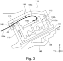
- Figure 3 is a sectional view of the reading unit 110 cut along a plane perpendicular to the X-direction.
- the glass 111 is stuck to a bottom (opening of the reading frame 119 having a substantially U-shape in cross section) of the reading unit 110 in which the CIS 112 is incorporated. Further, to each of opposite end portions of the glass 111 with respect to the X-direction (longitudinal direction of the CIS 112, main scan direction), a gap sheet 115 is stuck.
- Figure 4 shows a state of an IV-IV cross section of Figure 2 .
- the IV-IV cross section is a cross section obtained by cutting the reading unit 110 along a plane (plane extending in the X-direction and a sheet thickness direction D2 at a scanning position) perpendicular to a sheet feeding direction D1 at the scanning position of the reading unit 110.
- a shading plate 144 which is an opposing member opposing the glass 111.
- the gap sheets 115 function as a gap forming member for forming a gap between the glass 111 and the opposing member in contact with the opposing member opposing the glass 111.
- the gap forming member is not limited to the gap sheets 115 when the member ensures (defines) a width (range) of the gap, and for example, a projection projecting toward the glass 111 may be formed integrally with the reading frame 119.
- the shading plate 144 is mounted on the base conveying guide 143 which is a conveying guide opposing the reading unit 110, and the base conveying guide 143 is mounted on the frame of the ADF 10. That is, the shading plate 144 and the base conveying guide 143 are members fixed to the frame of the ADF 10.
- a pressing portion 114 for pressing the reading unit 110 is provided so stat the reading unit 110 is stably at rest at abutment positions of the glass sheets 115 ( Figure 4 ).
- the pressing portion 114 is provided at an upper portion (on a side opposite from the glass 111) of the reading unit 110.
- the pressing portion 114 includes a resin cover 114a as a contacted portion contacted to a pressing surface 141a ( Figure 2 ) provided on the bottom of the rotation guide 141, and a compression spring 114b as an elastic member interposed between the resin cover 114a and the reading frame 119.
- the rotation guide 141 includes a shaft portion 141c rotatably supported by the frame of the ADF 10 and is rotatable about a rotational axis A1 (second rotational axis).
- the rotational axis A1 is provided at an upstream end (one-side end portion with respect to the Y-direction) of the rotation guide 141 with respect to the sheet feeding direction of the sheet fed from the feeding roller 101 toward the separation roller pair 102, but may also be provided at another position.
- a supporting portion is not limited to the shaft portion 141c when the supporting portion is a supporting portion for rotatably supporting the rotation guide 141, and the rotation guide 141 may be provided with a hole (bearing portion) in which a shaft-shaped portion provided on the frame of the ADF 10 is engageable.
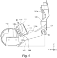
- the rotation guide 141 is rotatable between a position for guiding a lower surface of the original fed along the original conveying passage P1 (see Figure 2 , hereinafter, this position is referred to as a closed position) and a position moved upward from the closed position (see Figure 6 , hereinafter, this position is referred to as an open position).
- the closed position is a position (third position) where the rotation guide 141 covers the reading unit 110 as viewed from above
- the open position is a position (fourth position) where the rotation guide 141 exposes the reading unit 110 to the outside as viewed from above.
- the rotation guide 141 is held at the closed position by engaging a fixing portion 141d, provided at a free end portion thereof, with a conveying guide 142 fixed to the ADF main body 10B.
- the reading unit 110 includes a shaft portion 113 rotatably supported by the frame of the ADF 10, and is rotatable about another rotational axis A2 (third rotational axis) different from the rotational axis A1 of the rotation guide 141.
- the supporting portion is not limited to the shaft portion 113 when the supporting portion is capable of supporting the reading unit 110, and the read frame 119 may be provided with a hole (bearing portion) with which a shaft-shaped portion provided to the frame of the ADF 10 is engageable.
- the reading unit 110 is rotatable between a position where the image information is readable from the original fed along the original conveying passage P1 (see Figure 2 , hereinafter, this position is referred to as a reading position) and a position where the glass 111 is exposed to the outside (see Figure 6 , hereinafter, this position is referred to as a maintenance position).
- the reading position is a position (first position) of the reading unit 110 where the glass 111 which is a transparent member is in a state opposing the original conveying passage P1
- the maintenance position is a position (second position) of the reading unit 110 where the glass 111 is in an exposed state as viewed from the outside of the ADF 10.
- the maintenance position is a position of the reading unit 110 where at least a part (preferably a range encompassing a reading range of the CIS 112 or entirety of the glass 111 is exposed to the outside when the ADF 10 is viewed in a predetermined direction (for example, from above with respect to the vertical direction).
- the shaft portion 113 is provided so as to project from opposite end portions of the reading frame 119 toward the outside in the X-direction (longitudinal direction), and is held by a holding portion B1 provided. Accordingly, the rotational axis A1 of the rotation guide 141 and the rotational axis of the reading unit 110 is substantially parallel to each other and substantially extend in the X-direction.
- the holding portion B1 is a recessed portion (opening) rotatably holding the shaft portion 113, and the holding portion B1 in this embodiment is an elongated circular hole (groove portion) extending in the sheet thickness direction D2.
- the holding portion B1 as the elongated circular hole is, for example, provided on a side plate (plate-like member extending in the Y-direction and the Z-direction on a side out of an original passing region with respect to the X-direction) constituting the frame of the ADF 10.
- the rotational axis A1 of the rotation guide 141 is provided at an end portion of the rotation guide 141 on one end side (right-hand side of Figure 2 ) with respect to the Y-direction, and on the other hand, the shaft portion 113 in this embodiment is provided at an end portion of the reading unit 110 on the other end side (left-hand side of Figure 2 ) with respect to the Y-direction and on an upper side with respect to the Z-direction.
- the reading unit 110 is rotated counterclockwise (in a first rotational direction) in Figure 2 from the reading position toward the maintenance position
- the rotation guide 141 is rotated clockwise (in a second rotational direction) in Figure 2 from the closed position toward the open position.
- the arm 131 is a member which is rotatably supported by the frame of the ADF 10 and which moves the reading unit 110 from the reading position to the maintenance position by being rotated in interrelation with rotation of the rotation guide 141 from the closed position to the open position. That is, the arm 131 is an example of an interrelating mechanism for moving the reading unit 110 in interrelation with the rotation of the rotation guide 141.
- the arm 131 in this embodiment is a member which is rotated about the rotational axis A1 common to the arm 131 and the rotation guide 141 and which is rotatable independently of the rotation guide 141.
- the rotation guide 141 is provided with an arm contact portion 141b, and the arm 131 is provided with a contacted portion 131e to which the arm contact portion 141b is contactable.
- the arm contact portion 141b is spaced from the contacted portion 131e.
- arc profiles 131a, 131b and 131c as contact portions for urging (pressing) the reading unit 110. Details of the arc profiles 131a, 131b and 131c will be described later.
- a constitution in which the arm 131 is interrelated with the rotation guide 141 only within an integral range and in which a rotation range of the arm 131 is narrower than a rotation range of the rotation guide 141 is employed.
- the arm contact portion 141b of the rotation guide 141 does not contact the arm 131, and at an intermediary position during rotation of the rotation guide 141 toward the open position, the arm contact portion 141b contacts the arm 131 ( Figure 5A, Figure 5B ).
- a rotation locus of the arm 131 becomes small, so that a space required for disposing the arm 131 therein can be made small.
- the reading unit 110 is moved from the reading position shown in Figure 2 to the maintenance position shown in Figure 6 .
- the operator is capable of easily performing an operation such as cleaning of the glass 111 or the like for the reading unit 110 moved to the maintenance position.
- the rotation guide 141 can be constituted so that the reading unit 110 is held at the maintenance position through the arm 131 by being retained at the open position, for example, by a self-weight thereof.
- the pressing portion 114 of the reading unit 110 abuts against an abutment surface 142a ( Figure 6 ) of the conveying guide 142 fixed to the frame of the ADF main body 10A.
- the reading unit 110 is constituted so as to be rotatable about the rotational axis different from the rotational axis of the rotation guide 141, so that when the reading unit 110 is moved for performing the cleaning of the glass 111 or the jam clearance, the impact exerted on the reading unit 110 can be reduced.
- the holding portion B1 on a mating side (frame side of the ADF 10) to the shaft portion 113 of the reading unit 110 is constituted as the elongated circular hole extending in the sheet thickness direction.
- the holding portion B1 may also be constituted as a cylindrical hole corresponding to the shaft portion 113.
- the holding portion B1 is constituted as the elongated circular hole, so that in addition to rotation of the reading unit 110, movement of the reading unit 110 in the sheet thickness direction D2 is allowed.
- a variation in position of the reading unit 110 due to a part tolerance or the like of the ADF 10 can be absorbed by movement of the shaft portion 113.
- the variation in position of the reading unit 110 is absorbed, so that the glass 111 can be more stably positioned relative to the shading plate 144 through the gap sheet 115.
- the reading unit 110 in a state in which the reading unit 110 is rotated to the maintenance position, corresponding to a length of the holding portion B1, the reading unit 110 can be raised, and therefore, an operation property such as a maintenance property can be improved.
- the abutment surface 142a of the conveying guide 142 is constituted as an inclined surface with inclination along the holding portion B1, the abutment surface 142a also functions as a guide when the reading unit 110 is raised.
- a constitution in which the longitudinal direction of the elongated circular hole which is the holding portion B1 substantially coincides with the sheet thickness direction D2 of the reading unit 110 at the reading position was employed.
- the holding portion B1 is not limited thereto, but may also be an elongated circular hole extending in a direction, different from the sheet thickness direction D2, within directions crossing the sheet feeding direction D1 as viewed in the X-direction.
- the reading unit 110 is electrically connected to the controller 2C ( Figure 1B ) of the original reading apparatus 2 through the electric wire 150.
- the electric wire 150 is not only a signal line for transmitting, to the controller 2C, the image information read by the reading unit 110 but also an electric power line for supplying electric power to the reading unit 110.
- a flexible flat cable FFC
- the electric wire 150 is connected to the sensor substrate 112c inside the reading unit 110 and is led out to the outside of the reading unit 110 through an opening (outlet 146) provided in the reading frame 119.
- the electric wire 150 is wired inside the ADF main body 10A while being guided by a guiding member mounted on the frame of the ADF 10 and is connected to the controller 2C of the scanner portion 20.
- the electric wire 150 includes an inner unit portion 150a held in the reading unit 110, a main body-side portion 150b held by the frame of the ADF main body 10A, and an intermediary portion 150C connecting the inner unit portion 150a and the main body-side portion 150b.
- the intermediary portion 150c is a portion between the outlet 146 of the reading unit 110 and an inlet 149 (opening for receiving the electric wire 150 or guiding member for holding the electric wire 150) on the ADF main body 10A.
- the electric wire (FFC) 150 is disposed so that a widthwise direction of the electric wire 150 in the intermediary portion 150c is substantially parallel to the X-direction which is a main scan direction of the reading unit 110.
- the electric wire 150 is flexed, so that movement of the reading unit 110 is allowed. That is, when the reading unit 110 is rotated from a reading position shown in Figure 17A to a maintenance position shown in Figure 17B , principally the intermediary portion 150c of the electric wire 150 is flexed by following a change in attitude of the reading unit 110, so that the rotation of the reading unit 110 is allowed.
- the electric wire 150 is led out from an inside to an outside the reading unit 110 through the neighborhood of the rotational axis A2 of the reading unit 110.
- a distance from the reading unit 110 to the outlet 146 through which the electric wire 150 is led out is shorter than at least a distance from the rotational axis A1 (second rotational axis) of the rotation guide to the outlet 146. For that reason, compared with the case where the reading unit 110 is mounted on the rotation guide 141, a movement amount of the outlet 146 when the reading unit 110 is rotated becomes small.
- the neighborhood of the rotational axis A2 may preferably refers specifically to the case where the electric wire 150 passes through a position of the rotational axis A2 overlaps with the shaft portion 113 in a state in which these portions are viewed in the X-direction.
- an arrangement such that of four corner portions of the reading frame 119 having a substantially rectangular shape as viewed in the X-direction, one corner portion closest to the outlet 146 through which the electric wire 150 is led out and one corner portion closest to the shaft portion 113 are the same is suitable.
- the electric wire 150 is wired through the neighborhood of the rotational axis A2 of the reading unit 110, when the reading unit 110 is rotated about the rotational axis A2, the electric wire 150 is flexed principally in the neighborhood of the rotational axis A2 (see Figure 17B ). That is, the electric wire 150 is flexed so that the inner unit portion 150a of the electric wire 150 is rotated about the neighborhood of the rotational axis A2 as a supporting point. For that reason, a fluctuation in distance from the outlet 146 of the electric wire 150 on the reading unit 110 side to the inlet 149 of the electric wire 150 on the ADF main body 10A side is small.
- the fluctuation amount of the distance from the outlet of the electric wire 150 on the reading unit 110 side to the inlet of the electric wire 150 on the ADF main body 10A side is small, and therefore, even when the excessive length of the intermediary portion 150c is set at a small value, breakage or the like does not readily occur, so that the increase in cost and upsizing of the apparatus can be prevented.
- the conveying guide for guiding the sheet such as the rotation guide 141 is a relatively large member extending along the sheet conveying passage. For that reason, when such a large member is intended to be rotated, it is natural that the rotational axis of the conveying guide is disposed in the neighborhood of an upstream end or a downstream end of the conveying guide with respect to the feeding direction of the sheet to be guided.
- the reading unit is disposed at a position (below the rotation guide 141 in the case of the reading unit 110) apart from the guiding surface of the conveying guide so as not to prevent the feeding of the sheet, and therefore, it becomes difficult that the outlet of the electric wire from the reading unit is disposed in the neighborhood of the rotational axis of the conveying guide.
- the feeding roller for feeding the sheet is disposed in many cases, so that when the reading unit is intended to be disposed while avoiding interference with the feeding roller, it becomes further difficult that the outlet of the electric wire from the reading unit is disposed in the neighborhood of the rotational axis of the conveying guide.
- the reading unit 110 employs a mechanism rotatable separately from the rotation guide 141, and therefore, the electric wire 150 can be wired through the neighborhood of the rotational axis A2 of the reading unit 110. Further, the rotational axis A2 of the reading unit 110 can be disposed below the guiding surface of the rotation guide 141. As a result, as described above, the breakage of the electric wire 150 can be made hard to occur.
- the reading unit 110 assumes an attitude in the reading position such that the glass 111 faces downward with respect to the Z-direction and assumes an attitude in the maintenance position such that the glass 111 is exposed to the outside as viewed from above with respect to the Z-direction. That is, in this embodiment, the transparent member faces downward with respect to the vertical direction in a state in which the reading unit is positioned in the first position and faces upward with respect to the vertical direction in a state in which the reading unit is positioned in the second position.
- an angle of the inclination of the glass 111 is, for example, 45 degrees or less, preferably 30 degrees or less.
- the reading unit 110 is constituted so as to be rotatable between the read position and the maintenance position with a rotation range of, for example, 60 degrees or more, preferably 75 degrees or more, more preferably 90 degrees or more.
- the reading unit 110 is rotated within such a rotation range, in a constitution in which an operator directly puts one's hand on the reading unit 110, the hand is liable to be caught between the rotated reading unit 110 and another portion of the ADF 10, so that there was room for improvement in operating property.
- the free end portion of the arm 131 interrelated with the rotation of the rotation guide 141 is contacted to the reading unit 110 from below, so that the reading unit 110 is rotated in interrelation with the rotation guide 141 (see Figures 5 and 6 ).
- the arm 131 is rotated in a rotational direction opposite to the rotational direction of the reading unit 110, so that the reading unit 110 is moved from the reading position to the maintenance position while changing a contact position of the arm 131 with the reading unit 110.
- the operating property can be improved while enabling the rotation of the reading unit 110 within a wide rotation range.
- the reading unit 110 can be made movable from the reading position to the maintenance position with a small operating force to the extent possible, so that an operation load can be alleviated. In the following, this will be specifically described.
- Figure 7 shows a positional relationship between the reading unit 110, the rotational axis A1 of the arm 131, and the rotational axis A2 of the reading unit 110 when the arm 131 is first contacted to the reading unit 110.
- the first contact surface 110a which is a surface (where the glass 111 is disposed) on a lower side of the reading unit 110 in the reading position.
- a chain double-dashed line passing through each of the points is a rotation locus about the rotational axis A1 for an associated point, and an arrow represents a tangential direction (direction of a load when the reading unit 110 is pressed at the associated point) thereof.
- a load direction substantially extends toward the rotational axis A2 of the reading unit 110, and therefore, efficiency is poor for rotating the reading unit 110.
- moment in the clockwise direction in Figure 7 which is a direction opposite to a direction in which the operator intends to rotate the reading unit 110 acts on the reading unit 110.
- the reading unit 110 is rotated even when the load required to press the reading unit 110 by the arm 131 is relatively small.
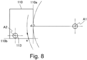
- Figure 8 shows a maximum angle at which the reading unit 110 can be rotated by pushing the first contact surface 110a from below. If the arm 131 is contacted to the first contact surface 110a at a point d, when the reading unit 110 is rotated to a position where the first contact surface 110a is vertically disposed, at the point d, the arm 131 cannot further press the reading unit 110. In order to further rotate the reading unit 110, as shown at a point e, a constitution in which the arm 131 contacts and presses the reading unit 110 at the second contact surface 110b different from the first contact surface 110a is employed.
- first arc profile 131a is a first projection for pressing the first contact surface 110a (first surface) of the reading unit 110.
- the third arc profile 131c is a third projection for pressing the second contact surface 110b (second surface) of the reading unit 110.
- the second arc profile 131b is an arcuately curved surface which is concaved between the first arc profile 131a and the third arc profile 131c and which forms a space for receiving a corner portion 110c between the first contact surface 110a and the second contact surface 110a.
- the first contact surface 110a and the second contact surface 110c are adjacent two surfaces (surfaces crossing perpendicularly each other) of the reading unit 110 which has a substantially rectangular shape as viewed in the X-direction, but surfaces extending in directions crossing each other at an angle different from a right angle may be the first surface and the second surface, respectively.
- the first contact surface 110a of the reading unit 110 is a surface of the glass sheet 115 (gap forming member) sticked to the glass 111.
- the arm 131 is prevented from directly contacting the glass 111, whereby a possibility that the glass 111 is changed is reduced.
- a contact position of the arm 131 with the gap sheet 115 is deviated from an abutment region of the shading plate 144 against the gap sheet 115 in the X-direction. For that reason, even when the surface of the first contact surface 110a of the gap sheet 115 to which the arm 131 is repetitively contacted is roughened, accuracy of a gap width (range) formed between the glass 111 and the shading plate 144 is not lowered.
- the first arc profile 131a contacts the first contact surface 110a of the reading unit 110 and causes the reading unit 110 to start to rotate from the reading position.
- the third arc profile 131c does not contact the second contact surface 110b of the reading unit 110.
- the third arc profile 131c contacts the second contact surface 110b, and the first arc profile 131a is separated from the first contact surface 110a. Then, the third arc profile 131c presses the second contact surface 110b, so that as shown in Figure 6 , the reading unit 110 is rotated to the maintenance position.
- the pressing portion 114 of the reading unit 110 abuts against the abutment surface 142a of the conveying guide 142 fixed to the frame of the ADF main body 10A.
- the elastic member compression spring 114b
- an impact of abutment of the reading unit 110 against the conveying guide 142 is alleviated. That is, the pressing portion 114 performs not only positioning action on the reading unit 110 during the image reading but also a function of a buffer when the reading unit 110 is moved to the maintenance position.
- a constitution in which the contact position between the arm 131 and the reading unit 110 is switched depending on the rotation angle of the reading unit 110 is employed, so that while the reading unit 110 is made rotatable in the wide rotation range, an operation load can be alleviated.
- a recessed arc profile 131c is provided between the two projections of the arm 131 contacting the first contact surface 110a and the second contact surface 110b of the reading unit 110, and therefore, the arm 131 and the reading unit 110 are not put in a locked state by the two projections.
- the corner portion 110c between the first contact surface 110a and the second contact surface 110b is accommodated in a space inside the arc profile 131c, so that the state between the arm 131 and the reading unit 110 is smoothly shifted from a contact state between the first arc profile 131a and the first contact surface 110a to a contact state between the third arc profile 131c and the second contact surface 110b.
- the three arc profiles 131a, 131b and 131c are smoothly connected to each other (i.e., a tangential direction is not changed discontinuously), and therefore, even when the contact position of the reading unit 110 is switched between the respective profiles, smooth rotation can be realized.
- each of the two projections and the recess between the two projections is constituted by the arcuate curves was described, but these portions may also be constituted as curves other than the arcuate curves.
- the constitution in which the reading unit 110 is rotated in interrelation with opening and closing of the rotation guide 141 through the arm 131 moved in interrelation with the opening and closing of the rotation guide 141 was described.
- the present invention is not limited thereto, and a constitution as shown in Figure 9 in which the arm 131 is not provided and in which the operator directly rotates the reading unit 110 by one's hand(s) may be employed.
- the operator in order to move the reading unit 110 to the maintenance position, the operator first rotates the rotation guide 141 from the closed position to the open position while holding the rotation guide 141, and then rotates the reading unit 110 from the reading position to the maintenance position while holding the reading unit 110.
- a constitution in which a part of the rotation guide 141 is contacted to the reading unit 110 in a manner such that the arm 131 is formed integrally with the rotation guide 141 may be employed.
- the constitution in which the arm 131 is rotatable relative to the rotation guide 141 and in which the rotation range of the arm 131 is narrower than the rotation range of the rotation guide 141 is employed, and therefore, as described above, downsizing of the apparatus can be realized compared with this modified embodiment.
- the arm 131 is disposed on one side of the reading unit 110 and the rotation guide 141 with respect to the X-direction, but the arm 131 may be disposed on each of opposite sides with respect to the X-direction. In that case, a torsional load is not readily exerted on the reading unit 110 and the rotation guide 141.
- FIG. 10 An embodiment 2 will be described using Figures 10 to 12 .
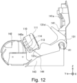
- This embodiment is different from the embodiment 1 in that a constitution in which in a state in which the rotation guide 141 is moved to the open position in advance, the operator holds and operates the operating portion of the arm 131 and thus rotates the reading unit 110 is employed.
- elements represented by reference numerals or symbols common to the embodiments 1 and 2 are regarded as those having substantially the same constitutions and functions, and an element different from those in the embodiment 1 will be principally described.
- the arm 131 in this embodiment is provided with an arm operating portion 131d as an operating portion (lever, handle).
- the arm operating portion 131d is disposed, for example, so as to project upward from the guiding surface of the rotation guide 141 on a front side of the image forming apparatus 1 relative to the rotation guide 141 in order to facilitate access by the operator in a state in which the upper portion cover 147 is opened.
- the arm operating portion 131d will be described as being rotated integrally with another portion of the arm 131, but may be connected rotatably relative to the aforementioned another portion so as to be interrelated with the aforementioned another portion only in a predetermined rotation range.
- the operator opens the upper portion cover 147 in advance, and then moves the rotation guide 141 to the open position. In this state, the operator puts one's hand on the arm operating portion 131a and rotates the arm 131 in the clockwise direction in Figure 10 .
- the arc profiles 131a and 131c provided on the free end portion side of the arm 131 contacts and presses the reading unit 110 and rotates the reading unit 110 about the shaft 113 in the counterclockwise direction in the figures.
- the reading unit 110 is moved from the reading position shown in Figure 10 to the maintenance position shown in Figure 11 .
- the reading unit 110 is constituted so as to be rotatable independently of the rotation guide 141, so that it is possible to reduce impact received by the reading unit 110 when the reading unit 110 is moved when cleaning of the glass 111 or the jam clearance is performed.
- the operator may only be required to operate the arm operating portion 131d in the case where the reading unit 110 is moved to the maintenance position, so that a possibility that the operator's hand is caught between the reading unit 110 and ADF main body 10A is low. Accordingly, the operating property can be improved while making the reading unit 110 rotatable within a wide rotation range.
- the reading unit 110 is constituted so as to be rotatable independently of the rotation guide 141, so that a breakage risk of the electric wire 150 when the reading unit 110 is rotated is capable of being reduced.
- FIG. 13 and 14 An embodiment 3 will be described using Figures 13 and 14 .
- This embodiment is different from the embodiment 1 in that in position of a rotational axis of the reading unit 110 and a rotational direction of the reading unit 110 are different from those in the embodiment 1.
- elements represented by reference numerals or symbols common to the embodiments 1 and 3 are regarded as those having substantially the same constitutions and functions, and an element different from those in the embodiment 1 will be principally described.
- the reading unit 110 includes the shaft portion 113 and is rotatable about a rotational axis A3 (second rotational axis) different from the rotational axis A1 of the rotation guide 141 as the conveying guide.
- the rotational axis A3 of the reading unit 110 is provided on one side of the Y-direction of the reading unit 110 (negative side of the Y-direction) and at an end portion on an upper side of the Z-direction. That is, in this embodiment, the first rotational axis is provided at an upstream-side end portion of the conveying guide with respect to the sheet feeding direction (leftward direction in Figure 13 ) of the sheet guided by the conveying guide.
- the second rotational axis is provided at the open position-side end portion of the reading unit with respect to the sheet feeding direction of the sheet guided by the conveying guide.
- the rotation guide 141 is rotated clockwise about the rotational axis A1 from the closed position toward the open position, and the reading unit 110 is rotated clockwise about the rotational axis A3 from the reading position to the maintenance position.
- the rotational directions of the rotation guide 141 and the reading unit 110 when the glass 111 as the transparent member is exposed to the outside are the same, it is possible to achieve effects similar to the effects of the embodiments 1 and 2.
- the rotational directions of the rotation guide 141 and the reading unit 110 are made the same direction or different directions is selected depending on a specific constitution of the ADF 10, such as a positional relationship of these members with members provided at a periphery of these members, or the like.
- the position of the rotational axis A3 of the reading unit 110 is different from those in the embodiments 1 and 2, and therefore, it is preferable that a wiring path of the electric wire 150 connected to the reading unit 110 is also changed from those in the embodiments 1 and 2.
- the electric wire 150 is led out from the inside to the outside of the reading unit 110 through the neighborhood of the rotational axis A3 of the reading unit 110.
- the electric wire 150 is different from the electric wire 150 in the embodiment 1, and is led out to the negative side of the Y-direction (downstream side of the sheet feeding direction in the reading position) and then is guided and wired by a guiding member 152 provided on the frame of the ADF main body 10A.
- a distance from the rotational axis A3 of the reading unit 110 to an outlet where the electric wire 150 is led out from the reading unit 110 is shorter than at least a distance from the rotational axis A1 of the rotation guide 141 to the outlet.
- the neighborhood of the rotational axis A3 is suitable when the electric wire 150 passes through a position where the rotational axis A3 overlaps with the shaft portion 113 in a state in which the rotational axis A3 is viewed specifically in the X-direction.
- FIG. 15 An embodiment 4 will be described using Figure 15 .
- This embodiment is different from the embodiment 2 in position of the rotational axis of the rotation guide 141 and the rotational direction of the rotation guide 141.
- elements represented by reference numerals or symbols common to the embodiments 2 and 4 are regarded as those having substantially the same constitutions and functions, and an element different from those in the embodiment 2 will be principally described.
- the rotation guide 141 as the conveying guide is provided rotatably about a rotational axis A4 (first rotational axis).
- the rotational axis A1 is provided at an end portion of the rotation guide 141 on a downstream side (left-hand side in Figure 15 , positive side of the Y-direction) with respect to the sheet feeding direction of the sheet guided by the rotation guide 141. That is, in this embodiment, the first rotational axis is provided at the downstream-side end portion of the conveying guide with respect to the sheet feeding direction of the sheet guided by the conveying guide.
- the second rotational axis is provided at a downstream-side end portion of the reading unit with respect to the sheet feeding direction of the sheet guided by the rotation guide.
- a modified embodiment will be described using Figure 16 .
- the position of the rotational axis A4 of the rotation guide 141 and the rotational direction of the rotation guide 141 in the embodiment 4, and the position of the rotational axis A3 of the reading unit 110 and the rotational direction of the reading unit 110 in the embodiment 3 are combined with each other. That is, in this modified embodiment, the first rotational axis is provided at the downstream-side end portion of the conveying guide with respect to the sheet feeding direction of the sheet guided by the conveying guide.
- the second rotational axis is provided at the upstream-side end portion of the reading unit with respect to the sheet feeding direction of the sheet guided by the conveying guide.
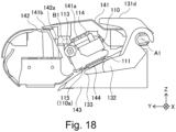
- FIG. 5 An embodiment 5 will be described using Figures 18 and 19 .
- This embodiment is different from the embodiment 2 in that a plurality of arm members are contacted to the first contact surface and the second contact surface of the reading unit.
- elements represented by reference numerals or symbols common to the embodiments 2 and 5 are regarded as those having substantially the same constitutions and functions, and an element different from those in the embodiment 2 will be principally described.
- the ADF 10 in this embodiment includes an arm 132 as a first arm member and an arm 133 as a second arm.
- the arms 132 and 133 are rotatably supported by the frame of the ADF main body 10A and are rotated about the rotational axis A1.
- the arms 132 and 133 overlap with each other as viewed in the X-direction. Further, the arms 132 and 133 can be rotated by operating the arm operating portion 131d. Even in such a constitution, an effect similar to the effect of the embodiment 1 can be achieved.
- the arm operating portion 131d is rotated in the clockwise direction from a state of Figure 18 .
- the arm 132 is rotated and contacted to the first contact surface 110a of the reading unit 110.
- the arm 133 starts rotation and is contacted to the second contact surface 110b of the reading unit 110.
- the reading unit 110 is rotated to the maintenance position.
- the arms 132 and 133 press a plurality of surfaces of the reading unit 110, so that it is possible to realize rotation of the reading unit 110 in a wide rotation range.
- FIG. 20 and 21 An embodiment 6 will be described using Figures 20 and 21 .
- This embodiment is different from the embodiment 2 in that a reading unit-side contact surface to which the arm member is contacted is made a curved surface and thus a rotation range of the reading unit is ensured.
- elements represented by reference numerals or symbols common to the embodiments 2 and 6 are regarded as those having substantially the same constitutions and functions, and an element different from those in the embodiment 2 will be principally described.
- the reading unit 110 in this embodiment includes an arm contact surface 110d different from the surface on which the glass 111 is disposed.
- the arm contact surface 110d is substantially arcuate curved surface which projects toward an upstream side of the rotational direction (downstream direction in Figure 20 ) of the arm 131 in a state in which the arm contact surface 110d is viewed in the X-direction.
- a free end of the arm 131 is formed in a substantially linear shape along a rectilinear line passing through the rotational axis A1.
- the arm contact surface 110d is the curved surface which is substantially continuous at least between a first contact point d1 ( Figure 20 ) and a second contact point d2 ( Figure 21 ).
- the first contact point d1 is a position where the reading unit 110 is contacted to the arm 131 in a state in which the reading unit 110 is positioned in the reading position.
- the second contact point d2 is a position where the reading unit 110 is contacted to the arm 131 in a state in which the reading unit 110 is positioned in the maintenance position.
- the present invention is applied to the image reading apparatus installed at an upper portion of the apparatus main assembly of the image forming apparatus was described.
- the present invention is not limited thereto, and is also applicable to an image reading apparatus which is independent of an image forming apparatus.
- An image reading apparatus for reading image information from a sheet includes a cover unit, a sheet feeding member, a conveying guide, and a reading unit including a transparent member and a reading portion.
- the cover unit is rotatable between a closed position where the cover unit forms a sheet conveying passage in cooperation with the conveying guide and an open position where the sheet conveying passage is open. In a state in which the cover unit is positioned in the closed position, the transparent member is exposed to an outside of the image reading apparatus by rotation of the conveying guide and the reading unit.
Landscapes
- Engineering & Computer Science (AREA)
- Multimedia (AREA)
- Signal Processing (AREA)
- Physics & Mathematics (AREA)
- General Physics & Mathematics (AREA)
- Facsimile Scanning Arrangements (AREA)
- Facsimiles In General (AREA)
- Feeding Of Articles By Means Other Than Belts Or Rollers (AREA)
- Holders For Sensitive Materials And Originals (AREA)
Applications Claiming Priority (2)
| Application Number | Priority Date | Filing Date | Title |
|---|---|---|---|
| JP2021105488A JP7718869B2 (ja) | 2021-06-25 | 2021-06-25 | 画像読取装置及び画像形成装置 |
| EP22176310.5A EP4109868B1 (de) | 2021-06-25 | 2022-05-31 | Bildlesevorrichtung und bilderzeugungsvorrichtung |
Related Parent Applications (2)
| Application Number | Title | Priority Date | Filing Date |
|---|---|---|---|
| EP22176310.5A Division EP4109868B1 (de) | 2021-06-25 | 2022-05-31 | Bildlesevorrichtung und bilderzeugungsvorrichtung |
| EP22176310.5A Division-Into EP4109868B1 (de) | 2021-06-25 | 2022-05-31 | Bildlesevorrichtung und bilderzeugungsvorrichtung |
Related Child Applications (1)
| Application Number | Title | Priority Date | Filing Date |
|---|---|---|---|
| EP26163273.1 Division-Into | 2026-03-09 |
Publications (3)
| Publication Number | Publication Date |
|---|---|
| EP4478697A2 true EP4478697A2 (de) | 2024-12-18 |
| EP4478697A3 EP4478697A3 (de) | 2025-03-05 |
| EP4478697B1 EP4478697B1 (de) | 2026-04-15 |
Family
ID=81854811
Family Applications (2)
| Application Number | Title | Priority Date | Filing Date |
|---|---|---|---|
| EP22176310.5A Active EP4109868B1 (de) | 2021-06-25 | 2022-05-31 | Bildlesevorrichtung und bilderzeugungsvorrichtung |
| EP24203809.9A Active EP4478697B1 (de) | 2021-06-25 | 2022-05-31 | Bildlesevorrichtung und bilderzeugungsvorrichtung |
Family Applications Before (1)
| Application Number | Title | Priority Date | Filing Date |
|---|---|---|---|
| EP22176310.5A Active EP4109868B1 (de) | 2021-06-25 | 2022-05-31 | Bildlesevorrichtung und bilderzeugungsvorrichtung |
Country Status (5)
| Country | Link |
|---|---|
| US (3) | US11689675B2 (de) |
| EP (2) | EP4109868B1 (de) |
| JP (2) | JP7718869B2 (de) |
| KR (1) | KR102849382B1 (de) |
| CN (3) | CN115524948B (de) |
Families Citing this family (6)
| Publication number | Priority date | Publication date | Assignee | Title |
|---|---|---|---|---|
| JP7250447B2 (ja) * | 2018-06-27 | 2023-04-03 | キヤノン株式会社 | シート搬送装置、画像読取装置及び画像形成装置 |
| JP7718869B2 (ja) * | 2021-06-25 | 2025-08-05 | キヤノン株式会社 | 画像読取装置及び画像形成装置 |
| US12486130B2 (en) * | 2022-07-13 | 2025-12-02 | Canon Kabushiki Kaisha | Image reading apparatus and image forming apparatus including the same |
| US12335446B2 (en) * | 2022-09-16 | 2025-06-17 | Canon Kabushiki Kaisha | Image reading apparatus and image forming apparatus comprising a reading portion, a first cover, a second cover and holding mechanism configured to prevent the first cover from moving to a second closed position and hold the first cover in the second open position |
| JP2024042831A (ja) * | 2022-09-16 | 2024-03-29 | キヤノン株式会社 | 画像読取装置及び画像形成装置 |
| JPWO2024150764A1 (de) | 2023-01-13 | 2024-07-18 |
Citations (2)
| Publication number | Priority date | Publication date | Assignee | Title |
|---|---|---|---|---|
| JP2016220232A (ja) | 2016-08-05 | 2016-12-22 | キヤノン株式会社 | 画像読取装置及び画像形成装置 |
| EP4109868A1 (de) | 2021-06-25 | 2022-12-28 | Canon Kabushiki Kaisha | Bildlesevorrichtung und bilderzeugungsvorrichtung |
Family Cites Families (26)
| Publication number | Priority date | Publication date | Assignee | Title |
|---|---|---|---|---|
| JPS62109554U (de) * | 1985-12-25 | 1987-07-13 | ||
| JP2004099240A (ja) * | 2002-09-10 | 2004-04-02 | Murata Mach Ltd | 画像読取装置 |
| US7379700B2 (en) | 2003-05-06 | 2008-05-27 | Canon Kabushiki Kaisha | Image reading apparatus with rotatable internal and external guides |
| JP4259325B2 (ja) | 2004-01-05 | 2009-04-30 | 村田機械株式会社 | 自動原稿搬送装置 |
| KR20060076573A (ko) * | 2004-12-29 | 2006-07-04 | 삼성전자주식회사 | 화상형성기기 |
| JP4500727B2 (ja) * | 2005-04-28 | 2010-07-14 | キヤノン株式会社 | 画像読取記録装置 |
| JP2007174497A (ja) * | 2005-12-26 | 2007-07-05 | Ricoh Co Ltd | 画像読取装置 |
| US8072653B2 (en) * | 2006-12-28 | 2011-12-06 | Canon Kabushiki Kaisha | Image reading and recording apparatus |
| KR20080064000A (ko) * | 2007-01-03 | 2008-07-08 | 삼성전자주식회사 | 화상형성기기 |
| JP4842190B2 (ja) * | 2007-03-29 | 2011-12-21 | キヤノン電子株式会社 | 画像読取装置、画像読取装置の制御方法、および制御プログラム |
| JP4618518B2 (ja) * | 2007-11-09 | 2011-01-26 | 村田機械株式会社 | 原稿読取装置 |
| JP4596033B2 (ja) * | 2008-04-14 | 2010-12-08 | 村田機械株式会社 | 原稿読取装置 |
| JP4941677B2 (ja) * | 2008-04-16 | 2012-05-30 | 村田機械株式会社 | 自動原稿搬送装置及びこれを備える原稿読取装置 |
| JP2010130422A (ja) * | 2008-11-28 | 2010-06-10 | Murata Machinery Ltd | 自動原稿搬送装置 |
| JP5170145B2 (ja) * | 2010-03-30 | 2013-03-27 | ブラザー工業株式会社 | 画像読取装置 |
| US20140320929A1 (en) * | 2013-04-30 | 2014-10-30 | Canon Kabushiki Kaisha | Image reading apparatus and image forming apparatus including the same |
| JP6146298B2 (ja) * | 2013-12-27 | 2017-06-14 | ブラザー工業株式会社 | シート搬送装置、及び画像読取装置 |
| JP6358011B2 (ja) * | 2014-09-22 | 2018-07-18 | ブラザー工業株式会社 | シート搬送装置、及び画像読取装置 |
| US9270837B1 (en) * | 2015-01-27 | 2016-02-23 | Lexmark International, Inc. | System for calibrating a stationary image capture module of an optical scanner |
| JP6512862B2 (ja) * | 2015-02-26 | 2019-05-15 | キヤノン株式会社 | シート搬送装置、画像読取装置、画像形成装置及びセンサユニット |
| JP6328083B2 (ja) * | 2015-09-07 | 2018-05-23 | キヤノン株式会社 | 画像読取装置及び画像形成装置 |
| JP7114373B2 (ja) * | 2018-07-06 | 2022-08-08 | キヤノン株式会社 | シート搬送装置、画像読取装置及び画像形成装置 |
| CN112055125A (zh) * | 2019-06-05 | 2020-12-08 | 佳能株式会社 | 片材传送装置、原稿读取装置和成像设备 |
| JP7358092B2 (ja) * | 2019-07-05 | 2023-10-10 | キヤノン株式会社 | 画像形成装置 |
| US11388302B2 (en) * | 2020-04-30 | 2022-07-12 | Canon Kabushiki Kaisha | Image forming apparatus |
| JP7547969B2 (ja) * | 2020-12-09 | 2024-09-10 | セイコーエプソン株式会社 | 画像読取装置 |
-
2021
- 2021-06-25 JP JP2021105488A patent/JP7718869B2/ja active Active
-
2022
- 2022-05-24 US US17/752,646 patent/US11689675B2/en active Active
- 2022-05-31 EP EP22176310.5A patent/EP4109868B1/de active Active
- 2022-05-31 EP EP24203809.9A patent/EP4478697B1/de active Active
- 2022-06-21 KR KR1020220075573A patent/KR102849382B1/ko active Active
- 2022-06-22 CN CN202210711934.0A patent/CN115524948B/zh active Active
- 2022-06-22 CN CN202511127473.2A patent/CN120972480A/zh active Pending
- 2022-06-22 CN CN202511127547.2A patent/CN120972481A/zh active Pending
-
2023
- 2023-05-12 US US18/316,888 patent/US12075012B2/en active Active
-
2024
- 2024-07-26 US US18/785,432 patent/US20240388666A1/en active Pending
-
2025
- 2025-07-22 JP JP2025122649A patent/JP2025146874A/ja active Pending
Patent Citations (2)
| Publication number | Priority date | Publication date | Assignee | Title |
|---|---|---|---|---|
| JP2016220232A (ja) | 2016-08-05 | 2016-12-22 | キヤノン株式会社 | 画像読取装置及び画像形成装置 |
| EP4109868A1 (de) | 2021-06-25 | 2022-12-28 | Canon Kabushiki Kaisha | Bildlesevorrichtung und bilderzeugungsvorrichtung |
Also Published As
| Publication number | Publication date |
|---|---|
| EP4109868A1 (de) | 2022-12-28 |
| EP4478697B1 (de) | 2026-04-15 |
| JP2023004032A (ja) | 2023-01-17 |
| KR102849382B1 (ko) | 2025-08-25 |
| CN120972481A (zh) | 2025-11-18 |
| EP4478697A3 (de) | 2025-03-05 |
| EP4109868C0 (de) | 2024-12-04 |
| US12075012B2 (en) | 2024-08-27 |
| JP2025146874A (ja) | 2025-10-03 |
| US11689675B2 (en) | 2023-06-27 |
| EP4109868B1 (de) | 2024-12-04 |
| JP7718869B2 (ja) | 2025-08-05 |
| CN115524948A (zh) | 2022-12-27 |
| CN115524948B (zh) | 2025-08-19 |
| US20220417374A1 (en) | 2022-12-29 |
| US20240388666A1 (en) | 2024-11-21 |
| CN120972480A (zh) | 2025-11-18 |
| US20230283724A1 (en) | 2023-09-07 |
| KR20230000974A (ko) | 2023-01-03 |
Similar Documents
| Publication | Publication Date | Title |
|---|---|---|
| EP4478697B1 (de) | Bildlesevorrichtung und bilderzeugungsvorrichtung | |
| JP5910937B2 (ja) | 原稿搬送装置、画像読取装置及び画像形成装置 | |
| US8160476B2 (en) | Latent image carrier having pairs of first and second positioning protrusions and image forming apparatus | |
| JP2008276138A (ja) | 画像形成装置およびカートリッジ | |
| CN110275416B (zh) | 框体结构及图像形成装置 | |
| US8965232B2 (en) | Positioning device to position a first member relative to a second member and image forming apparatus incorporating same | |
| US11835902B2 (en) | Image reading apparatus and image forming system | |
| JP7669169B2 (ja) | 画像形成装置 | |
| US11388302B2 (en) | Image forming apparatus | |
| JP7563142B2 (ja) | 画像形成装置 | |
| US11064081B2 (en) | Image forming apparatus | |
| JP5871178B2 (ja) | 現像剤補給装置及び画像形成装置 | |
| US20260039761A1 (en) | Image reading device and image forming apparatus | |
| JP2010072079A (ja) | 画像形成装置 | |
| US12459762B2 (en) | Sheet feeding device, image reading device and image forming apparatus | |
| US20260016787A1 (en) | Image forming apparatus | |
| US20260072394A1 (en) | Image forming apparatus | |
| US11480894B2 (en) | Image forming apparatus | |
| JP2024047668A (ja) | 画像形成装置および画像形成装置における剥離電界制御方法 | |
| CN121711435A (zh) | 图像读取装置和图像形成装置 | |
| JP2021196497A (ja) | 画像形成装置 | |
| US20170185005A1 (en) | Image forming device |
Legal Events
| Date | Code | Title | Description |
|---|---|---|---|
| PUAI | Public reference made under article 153(3) epc to a published international application that has entered the european phase |
Free format text: ORIGINAL CODE: 0009012 |
|
| STAA | Information on the status of an ep patent application or granted ep patent |
Free format text: STATUS: THE APPLICATION HAS BEEN PUBLISHED |
|
| AC | Divisional application: reference to earlier application |
Ref document number: 4109868 Country of ref document: EP Kind code of ref document: P |
|
| AK | Designated contracting states |
Kind code of ref document: A2 Designated state(s): AL AT BE BG CH CY CZ DE DK EE ES FI FR GB GR HR HU IE IS IT LI LT LU LV MC MK MT NL NO PL PT RO RS SE SI SK SM TR |
|
| REG | Reference to a national code |
Ref country code: DE Ref legal event code: R079 Free format text: PREVIOUS MAIN CLASS: H04N0001120000 Ref document number: 602022034850 Country of ref document: DE Ipc: H04N0001000000 |
|
| PUAL | Search report despatched |
Free format text: ORIGINAL CODE: 0009013 |
|
| AK | Designated contracting states |
Kind code of ref document: A3 Designated state(s): AL AT BE BG CH CY CZ DE DK EE ES FI FR GB GR HR HU IE IS IT LI LT LU LV MC MK MT NL NO PL PT RO RS SE SI SK SM TR |
|
| RIC1 | Information provided on ipc code assigned before grant |
Ipc: H04N 1/12 20060101ALI20250127BHEP Ipc: H04N 1/00 20060101AFI20250127BHEP |
|
| STAA | Information on the status of an ep patent application or granted ep patent |
Free format text: STATUS: REQUEST FOR EXAMINATION WAS MADE |
|
| 17P | Request for examination filed |
Effective date: 20250905 |
|
| GRAP | Despatch of communication of intention to grant a patent |
Free format text: ORIGINAL CODE: EPIDOSNIGR1 |
|
| STAA | Information on the status of an ep patent application or granted ep patent |
Free format text: STATUS: GRANT OF PATENT IS INTENDED |
|
| INTG | Intention to grant announced |
Effective date: 20251110 |
|
| GRAS | Grant fee paid |
Free format text: ORIGINAL CODE: EPIDOSNIGR3 |
|
| GRAA | (expected) grant |
Free format text: ORIGINAL CODE: 0009210 |
|
| STAA | Information on the status of an ep patent application or granted ep patent |
Free format text: STATUS: THE PATENT HAS BEEN GRANTED |
|
| AC | Divisional application: reference to earlier application |
Ref document number: 4109868 Country of ref document: EP Kind code of ref document: P |
|
| AK | Designated contracting states |
Kind code of ref document: B1 Designated state(s): AL AT BE BG CH CY CZ DE DK EE ES FI FR GB GR HR HU IE IS IT LI LT LU LV MC MK MT NL NO PL PT RO RS SE SI SK SM TR |
|
| REG | Reference to a national code |
Ref country code: CH Ref legal event code: F10 Free format text: ST27 STATUS EVENT CODE: U-0-0-F10-F00 (AS PROVIDED BY THE NATIONAL OFFICE) Effective date: 20260415 |
|
| REG | Reference to a national code |
Ref country code: DE Ref legal event code: R096 Ref document number: 602022034850 Country of ref document: DE |