EP4474759A2 - Bandmass mit umlaufgetriebeantrieb zum bandeinzug - Google Patents
Bandmass mit umlaufgetriebeantrieb zum bandeinzug Download PDFInfo
- Publication number
- EP4474759A2 EP4474759A2 EP24200199.8A EP24200199A EP4474759A2 EP 4474759 A2 EP4474759 A2 EP 4474759A2 EP 24200199 A EP24200199 A EP 24200199A EP 4474759 A2 EP4474759 A2 EP 4474759A2
- Authority
- EP
- European Patent Office
- Prior art keywords
- gear
- tape
- axle
- reel
- housing
- Prior art date
- Legal status (The legal status is an assumption and is not a legal conclusion. Google has not performed a legal analysis and makes no representation as to the accuracy of the status listed.)
- Pending
Links
Images







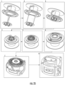
Classifications
-
- G—PHYSICS
- G01—MEASURING; TESTING
- G01B—MEASURING LENGTH, THICKNESS OR SIMILAR LINEAR DIMENSIONS; MEASURING ANGLES; MEASURING AREAS; MEASURING IRREGULARITIES OF SURFACES OR CONTOURS
- G01B3/00—Measuring instruments characterised by the use of mechanical techniques
- G01B3/10—Measuring tapes
- G01B3/1003—Measuring tapes characterised by structure or material; characterised by layout or indicia
-
- G—PHYSICS
- G01—MEASURING; TESTING
- G01B—MEASURING LENGTH, THICKNESS OR SIMILAR LINEAR DIMENSIONS; MEASURING ANGLES; MEASURING AREAS; MEASURING IRREGULARITIES OF SURFACES OR CONTOURS
- G01B3/00—Measuring instruments characterised by the use of mechanical techniques
- G01B3/10—Measuring tapes
-
- B—PERFORMING OPERATIONS; TRANSPORTING
- B65—CONVEYING; PACKING; STORING; HANDLING THIN OR FILAMENTARY MATERIAL
- B65H—HANDLING THIN OR FILAMENTARY MATERIAL, e.g. SHEETS, WEBS, CABLES
- B65H75/00—Storing webs, tapes, or filamentary material, e.g. on reels
- B65H75/02—Cores, formers, supports, or holders for coiled, wound, or folded material, e.g. reels, spindles, bobbins, cop tubes, cans, mandrels or chucks
- B65H75/34—Cores, formers, supports, or holders for coiled, wound, or folded material, e.g. reels, spindles, bobbins, cop tubes, cans, mandrels or chucks specially adapted or mounted for storing and repeatedly paying-out and re-storing lengths of material provided for particular purposes, e.g. anchored hoses, power cables
- B65H75/38—Cores, formers, supports, or holders for coiled, wound, or folded material, e.g. reels, spindles, bobbins, cop tubes, cans, mandrels or chucks specially adapted or mounted for storing and repeatedly paying-out and re-storing lengths of material provided for particular purposes, e.g. anchored hoses, power cables involving the use of a core or former internal to, and supporting, a stored package of material
- B65H75/44—Constructional details
- B65H75/48—Automatic re-storing devices
- B65H75/486—Arrangements or adaptations of the spring motor
-
- F—MECHANICAL ENGINEERING; LIGHTING; HEATING; WEAPONS; BLASTING
- F16—ENGINEERING ELEMENTS AND UNITS; GENERAL MEASURES FOR PRODUCING AND MAINTAINING EFFECTIVE FUNCTIONING OF MACHINES OR INSTALLATIONS; THERMAL INSULATION IN GENERAL
- F16H—GEARING
- F16H1/00—Toothed gearings for conveying rotary motion
- F16H1/28—Toothed gearings for conveying rotary motion with gears having orbital motion
- F16H1/46—Systems consisting of a plurality of gear trains each with orbital gears, i.e. systems having three or more central gears
-
- G—PHYSICS
- G01—MEASURING; TESTING
- G01B—MEASURING LENGTH, THICKNESS OR SIMILAR LINEAR DIMENSIONS; MEASURING ANGLES; MEASURING AREAS; MEASURING IRREGULARITIES OF SURFACES OR CONTOURS
- G01B3/00—Measuring instruments characterised by the use of mechanical techniques
- G01B3/10—Measuring tapes
- G01B3/1005—Means for controlling winding or unwinding of tapes
-
- G—PHYSICS
- G01—MEASURING; TESTING
- G01B—MEASURING LENGTH, THICKNESS OR SIMILAR LINEAR DIMENSIONS; MEASURING ANGLES; MEASURING AREAS; MEASURING IRREGULARITIES OF SURFACES OR CONTOURS
- G01B3/00—Measuring instruments characterised by the use of mechanical techniques
- G01B3/10—Measuring tapes
- G01B3/1005—Means for controlling winding or unwinding of tapes
- G01B3/102—Means for damping
-
- G—PHYSICS
- G01—MEASURING; TESTING
- G01B—MEASURING LENGTH, THICKNESS OR SIMILAR LINEAR DIMENSIONS; MEASURING ANGLES; MEASURING AREAS; MEASURING IRREGULARITIES OF SURFACES OR CONTOURS
- G01B3/00—Measuring instruments characterised by the use of mechanical techniques
- G01B3/10—Measuring tapes
- G01B3/1041—Measuring tapes characterised by casings
-
- G—PHYSICS
- G01—MEASURING; TESTING
- G01B—MEASURING LENGTH, THICKNESS OR SIMILAR LINEAR DIMENSIONS; MEASURING ANGLES; MEASURING AREAS; MEASURING IRREGULARITIES OF SURFACES OR CONTOURS
- G01B3/00—Measuring instruments characterised by the use of mechanical techniques
- G01B3/10—Measuring tapes
- G01B3/1041—Measuring tapes characterised by casings
- G01B3/1043—Details of internal structure thereof, e.g. means for coupling separately moulded casing halves
-
- G—PHYSICS
- G01—MEASURING; TESTING
- G01B—MEASURING LENGTH, THICKNESS OR SIMILAR LINEAR DIMENSIONS; MEASURING ANGLES; MEASURING AREAS; MEASURING IRREGULARITIES OF SURFACES OR CONTOURS
- G01B3/00—Measuring instruments characterised by the use of mechanical techniques
- G01B3/10—Measuring tapes
- G01B3/1056—Tape end arrangements, e.g. end-hooks
-
- G—PHYSICS
- G01—MEASURING; TESTING
- G01B—MEASURING LENGTH, THICKNESS OR SIMILAR LINEAR DIMENSIONS; MEASURING ANGLES; MEASURING AREAS; MEASURING IRREGULARITIES OF SURFACES OR CONTOURS
- G01B3/00—Measuring instruments characterised by the use of mechanical techniques
- G01B3/10—Measuring tapes
- G01B3/1005—Means for controlling winding or unwinding of tapes
- G01B2003/1023—Winding mechanisms
-
- G—PHYSICS
- G01—MEASURING; TESTING
- G01B—MEASURING LENGTH, THICKNESS OR SIMILAR LINEAR DIMENSIONS; MEASURING ANGLES; MEASURING AREAS; MEASURING IRREGULARITIES OF SURFACES OR CONTOURS
- G01B3/00—Measuring instruments characterised by the use of mechanical techniques
- G01B3/10—Measuring tapes
- G01B3/1005—Means for controlling winding or unwinding of tapes
- G01B2003/1023—Winding mechanisms
- G01B2003/103—Winding mechanisms operated by springs
Definitions
- the present invention relates generally to the field of tools.
- the present invention relates specifically to a tape measure, measuring tape, retractable rule, etc., that includes a spring-based retraction system having a gear train located between a tape reel and a rotatable axle and a spiral spring coupled between the reel and the rotatable axle.
- One embodiment of the invention relates to a tape measure with a spring-based retraction system including a reel and a spiral spring.
- the spiral spring includes an outer end coupled to the reel and an inner end that is coupled to an axle. Both the axle and reel are rotatably mounted within the tape measure housing.
- a gear train is coupled between the reel and the axle.
- the gear train may be configured such that every rotation of the reel during tape extension results in less than one rotation of the axle.
- the gear train may be an epicyclic gear train having a central rotational axis aligned with a rotational axis of the axle.
- the gear ratio of the gear train is greater than 1 and less than 2.
- the gear train defines a spring turn ratio, defined as the number of reel rotations per turn applied to the spring, and in some embodiments the spring turn ratio is 2 to 10, is 3 to 6, is 3 to 4, is 4 to 5, is 5 to 6 and/or is 3.5 to 4.5.
- Various embodiments of a tape measure are shown.
- Various embodiments of the tape measure discussed herein include an innovative retraction system designed to provide for a variety of desired retraction characteristics, including controlled/reduced retraction speed.
- Some tape measure blades are susceptible to damage/breakage due to high speed during retraction. For example, high speeds during retraction may cause the tape blade to whip (e.g., the tendency of the tape measure blade to bend or snap back on itself during fast retraction), which can crack or tear the tape blade, and similarly, high retraction speeds can damage the tape blade when the tape hook contacts the tape housing at the end of retraction.
- Applicant believes that the tape measure retraction system described herein provides for retraction speed control that can limit such sources of tape measure damage while at the same time providing a more compact tape measure without sacrificing tape length or retraction performance.
- the tape retraction system discussed herein utilizes a gear train having its input coupled to a rotating tape reel, the output coupled to a rotating central arbor or axle, and one portion coupled to a stationary tape measure housing.
- the tape retraction system also includes a spring, such as a spiral spring, coupled at its inner end to the rotating axle and at its outer end to the rotating tape reel.
- the gear train is a reduction gear train that translates each rotation of the tape reel to less than one rotation of the axle, and both the tape reel and the axle rotate together during tape extension and retraction.
- the gear train arrangement discussed herein provides for space savings within the reel, which can be utilized to further decrease spring size, allowing housing size to be decreased.
- the space savings provided by the retraction system arrangements discussed herein can be utilized to increase spring energy for a fixed housing size, which allows for a longer tape blade to be deployed within a smaller tape housing than would typically be needed to accommodate the longer tape length.
- the gear train operates in one direction during tape measure extension as the reel drives winding of the spiral spring, and the gear train operates in the opposite direction during tape measure retraction as the expanding spiral spring drives rotation of the reel and tape blade uptake.
- the directionality of the gear train e.g., input and output refers to operation of the gear train during tape extension, with the understanding that the gear train operates in the opposite direction during tape blade retraction.
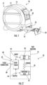
- tape measure 10 includes a housing 12 having a first part 14 and a second part 16.
- Tape measure 10 includes a tape blade 18 and, in the retracted position shown in FIGS. 1 and 2 , tape blade 18 is wound or coiled onto a tape reel 20.
- tape blade 18 is an elongated strip of material including a plurality of graduated measurement markings
- tape blade 18 is an elongated strip of metal material (e.g., steel material) that includes an outer most end coupled to a hook assembly 22.
- Tape blade 18 may include various coatings (e.g., polymer coating layers) to help protect tape blade 18 and/or the graduated markings of the blade from wear, breakage, etc.
- both reel 20 and axle 24 are rotating in the same direction, which in turn causes the inner end of spring 26 (coupled to axle 24) and the outer end of spring 26 (coupled to reel 20) to rotate in the same direction as each other.
- spring 26 between two rotating portions of retraction system 40, the number of turns that spring 26 experiences per rotation of reel 20 is substantially greater than the number of rotations axle 24 experiences per rotation of reel 20.
- spring 26 By providing gear reduction between tape reel 20 and axle 24, and by locating spring 26 between the rotating input and output of gear train 42, the number of turns spring 26 experiences for each rotation of reel 20 can be decreased by utilizing a gear train with a relatively low gear ratio.
- spring 26 By decreasing the number of turns of spring 26 (as compared to a standard spiral spring) needed to achieve full extension of tape blade 18 from reel 20, spring 26 can be formed from stiffer material that is more energy dense (spring energy stored per unit volume occupied by the spring) than a spring compliant enough to experience a high number of turns.
- gear train 42 is configured such that the Spring Turn Ratio is greater than 1, is between 2 to 10, is between 3 to 6, is between 3 to 4, is between 4 to 5, is between 5 to 6 or is between 3.5 to 4.5.
- the Spring Turn Ratio of gear train 42 is 3.95 to 4.05, and in another specific embodiment, the Spring Turn Ratio of gear train 42 is between 5.5 and 6.5, and specifically is 6.
- gear train 42 is configured such that the ratio of rotations of reel 20 to the rotations of axle 24 is between 1 to 2, is between 1.1 to 1.6, is between 1.2 to 1.5 (this embodiment correlates to the embodiment of gear train 42 with a Spring Turn Ratio between 3 to 6), is between 1.3 to 1.45 or is between 1.36 to 1.42. Applicant believes that retraction control systems having ratios within these ranges generally provide satisfactory torque profiles and spring sizes for tape measure applications.
- gear train 42 may be any one of a variety of epicyclic gear train designs.
- gear train 42 is any one of the gear arrangements shown and described in ANSI/AGMA 6123-B06.
- gear train 42 includes two or more epicyclic gear arrangements connected to each in series in which the input of a first epicyclic gear arrangement is coupled to reel 20, the output of the first epicyclic gear arrangement is coupled to the input of a second gear arrangement, and the output of the second epicyclic gear arrangement is coupled to axle 24. This pattern can be repeated for gear trains 42 that include, 3, 4, 5, etc. epicyclic gear trains in series.
- gear train 42 is a gear arrangement not described in ANSI/AGMA 6123-B06.
- sun gear 52 is rigidly coupled to tape housing 12 and provides fixed connection 48 between planetary gear train 50 and housing 12.
- Sun gear 52 defines an axis of rotation of gear train 50 that is co-linear with rotation axis 28 of tape measure 10.
- sun gear 52 is a gear structure that extends inward from an inner surface of tape housing 12.
- sun gear 52 is a structure that is integrally formed or molded with a component of housing 12, and in another embodiment, sun gear 52 is a separate piece coupled (e.g., through an adhesive, weld, friction fit, etc.) to the inner surface of housing 12.
- Outer ring gear 54 is rigidly coupled to reel 20. As shown in FIG. 3 , outer ring gear 54 is formed on an annular flange 60 that extends outward from reel 20. As will be understood (see FIG. 5 ), outer ring gear 54 includes gear teeth extending radially inward from an inner, generally cylindrical surface of annular flange 60 such that outer ring gear 54 surrounds rotation axis 28. In some embodiments, outer ring gear 54 and reel 20 are integrally formed or molded from a single, contiguous and continuous piece of material, and in another embodiment, outer ring gear 54 is a separate piece coupled (e.g., through an adhesive, weld, friction fit, etc.) to an outer surface of reel 20.
- Planetary gears 58 are mounted to posts 62 of gear carrier 56.
- Gear carrier 56 is rigidly (e.g., non-rotationally) coupled to axle 24.
- the gear teeth of planetary gears 58 interface with gear teeth of outer ring gear 54 and with the gear teeth of fixed sun gear 52.
- the interface between outer ring gear 54 and planetary gears 58 translates rotational motion of reel 20 to planetary gears 58.
- planetary gears "orbit” around sun gear 52 which, in turn translates the orbital movement of planetary gears 58 to gear carrier 56 and to axle 24.
- planetary gear train 50 results in rotation of axle 24 in the same direction as reel 20, such that spiral structure of spring 26 is coiled in the same direction as tape 18 on reel 20.
- the arrangement of planetary gear train 50 relative to spring 26 and reel 20 shown in FIG. 3 provides further space savings.
- spring 26 is coupled directly between reel 20 and axle 24, which allows spring 26 to be sized to fill the entire cross-sectional diameter of internal chamber 64 of reel 20.
- the outermost coil of spring 26 faces the inner cylindrical surface of reel 20 without a component of planetary gear train 50 located between spring 26 and reel 20.
- planetary gear train 50 further provides for a relatively low number of moving components.
- planetary gear train 50 only results in a relatively minor addition to tape measure width as only one layer of gearing is arranged in the width direction between housing 12 and reel 20/axle 25.
- tape measure 10 may include a gear train, shown as gear train 70.
- Gear train 70 is an exemplary embodiment of gear train 42 discussed above regarding FIG. 2 .
- gear train 70 includes a pair of opposing planetary gear trains 50.
- one planetary gear train 50 is located on one side of reel 20 and a second planetary gear train 50 is located on the other side of reel 20.
- spring 26 is located within reel 20 and located between the two opposing planetary gear trains 50 along axis of rotation 28.
- tape measure 10 may include a gear train, shown as gear train 80.
- Gear train 80 is an exemplary embodiment of gear train 42 discussed above regarding FIG. 2 .
- gear train 80 is an epicyclic gear train and includes an outer ring gear 82, an inner ring gear 84 and at least two planetary gears 86.
- Outer ring gear 82 is rigidly coupled to reel 20. As shown in FIG. 6 , outer ring gear 54 is located on annular flange 60 that extends outward from reel 20. As will be understood (see FIG. 5 ), outer ring gear 82 includes gear teeth extending radially inward from an inner, generally cylindrical surface of annular flange 60. In some embodiments, outer ring gear 82 and reel 20 are integrally formed or molded from a single, contiguous and continuous piece of material, and in another embodiment, outer ring gear 82 is a separate piece coupled (e.g., through an adhesive, weld, friction fit, etc.) to an outer surface of reel 20.
- Each planetary gear 86 is rotationally mounted to posts 88 that are rigidly coupled to the inner surface of housing 12.
- Posts 88 are rigidly coupled to tape housing 12 such that planetary gears 86 are prevented from translating relative to housing 12 but are permitted to spin or rotated about posts 88 to translate rotation to axle 24. In this manner, posts 88 provide the fixed connection ( see connection 48 in FIG. 2 ) between gear train 80 and housing 12.
- Each planetary gear 86 includes an outer or high gear section 90 and an inner or low gear section 92.
- Inner ring gear 84 is rigidly coupled axle 24 through plate 94.
- inner ring gear 84 and/or plate 94 are integrally formed or molded from a single, contiguous and continuous piece of material with axle 24, and in another embodiment, inner ring gear 84 and/or plate 94 are separate pieces coupled (e.g., through an adhesive, weld, friction fit, etc.) to axle 24.
- outer ring gear 82 engages high gear section 90 of each planetary gear 86 such that rotation of reel 20 translates into rotation of each planetary gear 86 about its post 88.
- Low gear section 92 of each planetary gear 86 engages inner ring gear 84 such that rotation of the planetary gears 86 translates into rotation of inner ring gear 84.
- gear train 80 results in rotation of axle 24 in the same direction as reel 20, such that spiral structure spring 26 is coiled in the same direction as tape 18 on reel 20.
- tape measure 10 may include a gear train, shown as gear train 100.
- Gear train 100 is an exemplary embodiment of gear train 42 discussed above regarding FIG. 2 .
- gear train 100 is an epicyclic gear train and includes a small sun gear 102, a large sun gear 104 and at least two planetary gears 106.
- small sun gear 102 is rigidly coupled to tape housing 12 and provides fixed connection 48 (see FIG. 2 ) between gear train 100 and housing 12.
- small sun gear 102 is a gear structure that extends inward from an inner surface of tape housing 12.
- small sun gear 102 is a structure that is integrally formed or molded with a component of housing 12, and in another embodiment, sun small gear 102 is a separate piece coupled (e.g., through an adhesive, weld, friction fit, etc.) to the inner surface of housing 12.
- large sun gear 104 is rigidly coupled to axle 24 and has an outer diameter greater than that of small sun gear 102.
- large gear 104 is a gear structure that extends outward from one of the outer ends of axle 24 in the direction of rotation axis 28.
- large sun gear 104 is a structure that is integrally formed or molded with the end of axle 24, and in another embodiment, large sun gear 104 is a separate piece coupled (e.g., through an adhesive, weld, friction fit, etc.) to the end of axle 24.
- Gear train 100 includes at least two planetary gears 106 that are mounted to posts 108.
- Posts 108 extend outward in a direction parallel to rotational axis 28 from outer lateral surfaces of reel 20. In this manner, posts 108 couple planetary gears 106 to reel 20.
- Each planetary gear 106 includes an outer or high gear section 110 and an inner or low gear section 112. As shown in FIG. 9 , the outer diameter of each high gear section 110 is greater than the outer diameter of low gear section 112. The gear teeth of high gear section 110 engage with small sun gear 102, and the gear teeth of low gear section 112 engage with large sun gear 104.
- gear train 100 results in rotation of axle 24 in the same direction as reel 20, such that spiral structure spring 26 is coiled in the same direction as tape 18 on reel 20.
- tape measure 10 may include a gear train, shown as gear train 120.
- Gear train 120 is an exemplary embodiment of gear train 42 discussed above regarding FIG. 2 .
- Gear train 120 is similar to gear train 42 shown in FIG. 3 except as discussed herein.
- gear train 120 is an epicyclic gear train and includes a central or sun gear 52, an outer ring gear 54, a gear carrier 56 and at least two planetary gears 122.
- Each planetary gear 122 includes an outer or high gear section 124 and an inner or low gear section 126.
- Planetary gears 122 are mounted to posts 128 of gear carrier 56.
- the gear teeth of low gear section 126 of planetary gears 122 interface with gear teeth of outer ring gear 54.
- the gear teeth of high gear section 124 of planetary gears 122 interface with the gear teeth of fixed sun gear 52. In this arrangement, as reel 20 rotates during tape extension, the interface between outer ring gear 54 and the gear teeth of low gear section 126 of planetary gears 122 translates rotational motion of reel 20 to planetary gears 122.
- gear train 120 results in rotation of axle 24 in the same direction as reel 20, such that spiral structure spring 26 is coiled in the same direction as tape 18 on reel 20.
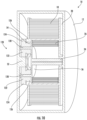
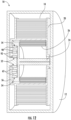
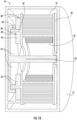
- FIGS. 11-18 show tape measure 10 including various epicyclic gear train arrangements according to additional exemplary embodiments.
- the gear train arrangements shown in FIGS. 11-18 are similar to those discussed above, in that they provide gear reduction between the reel and the axle such that the number of turns applied to the spring per reel revolution is decreased.
- gear carrier 56 is coupled to housing 12 and includes posts 62, around which inner planetary gear 92 and outer planetary gear 90 are rotatably mounted.
- the gear teeth of outer planetary gear 90 interface with outer ring gear 82 and inner planetary gear 92, the gear teeth of which also interface with inner ring gear 84.
- Outer ring gear 82 is coupled to axle 24, inner ring gear 84 is coupled tape reel 20, and spring 26 is coupled between tape reel 20 and axle 24.
- gear carrier 56 is coupled to tape reel 20 and includes posts 62, around which inner planetary gear 92 and outer planetary gear 90 are rotatably mounted.
- the gear teeth of outer planetary gear 90 interface with outer ring gear 54 and inner planetary gear 92, the gear teeth of which also interface with sun gear 52.
- Sun gear 52 is coupled to housing 12
- outer ring gear 54 is coupled to axle 24, and spring 26 is coupled between tape reel 20 and axle 24.
- gear carrier 56 is coupled to axle 24 and includes posts 62, around which inner planetary gear 92 and outer planetary gear 90 are rotatably mounted.
- the gear teeth of outer planetary gear 90 interface with outer ring gear 54 and inner planetary gear 92, the gear teeth of which also interface with sun gear 52.
- Outer ring gear 54 is coupled to tape reel 20
- sun gear 52 is coupled to housing 12
- spring 26 is coupled between tape reel 20 and axle 24.
- gear carrier 56 is coupled to axle 24 and includes posts 62, around which inner planetary gear 92 and outer planetary gear 90 are rotatably mounted.
- the gear teeth of outer planetary gear 90 interface with outer ring gear 54 and inner planetary gear 92, the gear teeth of which also interface with sun gear 52.
- Outer ring gear 54 is coupled to tape reel 20
- sun gear 52 is coupled to housing 12
- spring 26 is coupled between tape reel 20 and axle 24.
- gear carrier 56 is coupled to axle 24 and includes posts 62, around which inner planetary gear 92 and outer planetary gear 90 are rotatably mounted.
- the gear teeth of outer planetary gear 90 interface with outer ring gear 82 and inner planetary gear 92, the gear teeth of which also interface with inner ring gear 84.
- Outer ring gear 82 is coupled to tape reel 20
- inner ring gear 84 is coupled to housing 12
- spring 26 is coupled between tape reel 20 and axle 24.
- gear carrier 56 is coupled to axle 24.
- Tape reel 20 includes posts 62, around planetary gear 58 is rotatably mounted.
- the gear teeth of inner planetary gear 92 interface with outer ring gear 82, and the gear teeth of outer planetary gear 90 interface with inner ring gear 84.
- Outer gear ring 82 is coupled to housing 12
- inner gear ring 84 is coupled to gear carrier 56
- spring 26 is coupled between tape reel 20 and axle 24.
- gear carrier 56 is coupled to axle 24.
- Posts 62 are coupled to tape reel 20, and planetary gears 58 are rotatably mounted to posts 62.
- the gear teeth of outer planetary gear 90 interface with outer ring gear 82, and the gear teeth of inner planetary gear 92 interface with inner ring gear 84.
- Outer gear ring 82 is coupled to housing 12
- inner gear ring 84 is coupled to gear carrier 56
- spring 26 is coupled between tape reel 20 and axle 24.
- gear carrier 56 is coupled to axle 24 and includes posts 62, around which inner planetary gear 92 and outer planetary gear 90 are rotatably mounted.
- the gear teeth of outer planetary gear 90 interface with inner ring gear 84 and inner planetary gear 92, the gear teeth of which also interface with outer ring gear 82.
- Inner gear ring 84 is coupled to tape reel 20
- outer ring gear 82 is coupled to housing 12
- spring 26 is coupled between tape reel 20 and axle 24.
- tape measure 10 may include one or more structures configured to reduce friction while tape reel or spool 20 is rotating (e.g., while housing 12 is paying out or retrieving tape blade 18).
- spool 20 On the left side of spool 20 in FIG. 19 , spool 20 is supported radially by axle or carrier 24 at contact surface 150.
- spool 20 On the right side of spool 20 in FIG. 19 , spool 20 is indirectly supported radially by carrier 24 via spool cover 132 at contact surface 150.
- carrier 24 itself is confined by housing 12 at contact surface 150.
- carrier 24 has a diameter of 5 mm and is created from diecast Zinc, although it is contemplated herein that other diameters, manufacturing methods and/or materials may be utilized and still practice the disclosure herein.
- Contact surfaces 150 which include the bearing interfacing surfaces of spool 20 and spool cover 132, are located directly around carrier 24.
- the area of contact surfaces 150 is reduced because the diameter of the bearing surface is smaller relative to other embodiments in which the bearing surface is located at an increased diameter from carrier 24. As a result, the amount of energy lost to friction while spool 20 rotates is concurrently reduced. Therefore less torque is required to provide full retraction of spool 20 and of the tape blade.
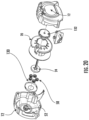
- Tape measure 10 includes dust cover 130, which at least partially encloses the interface between planetary gears 58 and both sun gear 52 and outer ring gear 54 (best shown in FIG. 20 ).
- spring 26 is anchored to carrier 24 and spool 20, and planetary gears 58 interface with and rotate around sun gear 52 (best shown in FIG. 20 ).
- the outer periphery of planetary gears 58 also interface with outer ring gear 54.
- Both spool 20 (also referred to as tape reel 20) and carrier 24 (also referred to as axle 24) rotate about the longitudinal axis of axle 24 relative to and within housing 12.
- tape measure 10 also may include spool cover 132, which is located on the opposite side of spool 20 relative to dust cover 130.
- Spool cover 132 at least partially encloses internal chamber 64 of spool 20 where spring 26 is disposed.
- Spool cover 132 is rotatably fixed to spool 20 and rotates about carrier 24.
- the tabs in spool cover 132 allow for easy rotational locking with spool 20 during assembly.
- Support ring 134 furthers a more secure coupling between spool cover 132 and spool 20, thus reducing a chance of decoupling if tape measure 10 is dropped.
- spool cover 132 is not fixed to spool 20, and instead is permitted to rotate independently with respect to both carrier 24 and spool 20.
- tape measure 10 is designed to create a direct load path between the primary mass of tape measure 10 (typically tape blade 18 and spring 26) into housing 12 which improves durability and stability, for example during impact if tape measure 10 is dropped.
- Another aspect and advantage of this embodiment is that input torque is converted to higher turns at a lower torque, which is reacted at sun gear 52 / front housing 12, causing tape reel 20 to rotate.
- spring 26 is anchored to carrier 24 and spool 20.
- Carrier 24 spins freely with respect to housing 12 and spool 20. Further, when tape blade 18 is being either paid out or retrieved into housing 12, carrier 24 spins in the same direction as spool 20, but at a slightly slower speed than spool 20.
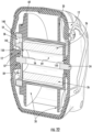
- spool 20 is radially supported by housing 12 on the right side of FIG. 22 at contact surface 150, and by hubcap 140 on the left side of FIG. 22 at contact surface 150.
- Contact surfaces 150 which include the bearing interfacing surfaces of spool 20 and hubcap 140, are located around housing 12 as indicated in FIG. 22 . Therefore, the area of contact surfaces 150 is slightly increased relative to FIG. 19 because the diameters of the bearing surfaces in FIG. 22 are relatively larger.
- Hubcap 140 partially encloses the interface between planetary gears 58 and outer ring gear 54.
- Hubcap 140 is rotatably fixed to spool 20 (e.g., via rivets, screws, and/or fasteners).
- hubcap 140 extends from annular flange 60 to approximate a radially interior edge of planetary gears 58. In this configuration hubcap 140 helps prevent contamination from entering the gear assembly.
- hubcap 140 may have other configurations.
- membrane 142 Also included in the embodiment in FIG. 22 is membrane 142. Membrane 142 separates internal chamber 64 from the gears, including sun gear 52, planetary gears 58, and outer ring gear 54 (best shown in FIGS. 22 and 23 ).
- outer ring gear 54 is configured to be disposed within an opening in spool 20 (best shown in FIG. 23 ), such that outer ring gear 54 and spool 20 are rotatably fixed together.
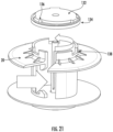
- carrier 24 includes gear carrier 56, which extends radially from the primary axis of carrier 24. Protruding from gear carrier 56 are several posts 62, upon which planetary gears 58 are disposed, and around which planetary gears 58 axially rotate. In the embodiment illustrated in FIG. 24 , carrier 24 includes five posts 62, although it is contemplated herein that any number of posts may be utilized, such as for exemplary purposes only and without limitation, 3-6 posts. Further, in one or more embodiments, such as FIG. 24 , posts 62 are symmetrically located on gear carrier 56 with respect to each other. It should be understood that while carrier 56 is shown as circular, in other embodiments carrier 56 may be any other suitable shape such as hexagonally shaped, D-shaped, oval shaped, an X-sided polygon, etc.
- carrier 24 has a diameter of 4.63 mm and is created from diecast Zinc, although it is contemplated herein that other diameters, manufacturing methods and/or materials may be utilized and still practice one or more disclosures herein.
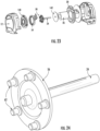
- FIG. 25 a method of assembly of an epicyclic geared tape measure, such as tape measure 10, is shown.
- one side of membrane 142 is slightly lubricated, such as with grease.
- Membrane 142 is installed onto carrier 24 with the greased side of membrane 142 facing carrier 24.
- Spring 26 is formed around the axle of carrier 24 at step 2, and then wound.
- An external tail of spring 26 is captured, spool 20 is placed around spring 26 at step 3, and the external tail of spring 26 is anchored to spool 20.
- Planetary gears 58 are lightly lubricated (e.g., with grease) between planetary gears 58 and posts 62, and then planetary gears 58 are placed on posts 62 at step 4.
- Outer ring gear 54 is placed around planetary gears 58 and the teeth of planetary gears 58 are lightly lubricated at step 5.
- hubcap 140 is then placed over the gear assembly and fixedly attached to spool 20 (e.g., via screws).
- the spool assembly is placed into housing 12 (e.g., front housing) that includes sun gear 52, such that planetary gears 58 are interfaced with sun gear 52.
- the rest of tape measure 10 is assembled, such as attaching a rear housing, a bumper, a brake, and/or housing screws to attach the housings.
- the relative rotational speed of arbor 24 to spool 20 is partly based on whether tape blade 18 and spring 26 are wound in the same direction.
- spring 26 is anchored to spool 20 on one end and to arbor 24 on the other end.
- spool 20 and arbor 24 rotate in the same direction as each other when tape blade 18 is being either extracted or retracted.
- Spool 20 and arbor 24 are both coupled to housing 12 through gear train 42.
- Tape blade 18 is wound around spool 20, and when tape blade 18 is extended from housing 12, energy is stored in spring 26 through the rotations of arbor 24 and spool 20.
- spring 26 and tape blade 18 are wound in the same direction and as a result spool 20 rotates faster than arbor 24.
- spool 20 rotates 4 times while arbor 24 rotates 3 times, and the result is one turn of force is applied to spring 26 (instead of 4 turns as in a typical tape measure in which housing 12, spring 26, spool 20, and arbor 24 are in series).
- case spring 26 and tape blade 18 are wound in opposite directions and as a result, arbor 24 rotates faster than spool 20.
- arbor 24 rotates faster than spool 20.
- spool 20 rotates 4 times while arbor 24 rotates 5 times, and the result is one turn applied to the spring (instead of 4 turns as in a typical tape measure).
Landscapes
- Physics & Mathematics (AREA)
- General Physics & Mathematics (AREA)
- Engineering & Computer Science (AREA)
- General Engineering & Computer Science (AREA)
- Mechanical Engineering (AREA)
- Tape Measures (AREA)
- Gear Transmission (AREA)
- Testing, Inspecting, Measuring Of Stereoscopic Televisions And Televisions (AREA)
Applications Claiming Priority (4)
| Application Number | Priority Date | Filing Date | Title |
|---|---|---|---|
| US201762474872P | 2017-03-22 | 2017-03-22 | |
| US201762598890P | 2017-12-14 | 2017-12-14 | |
| EP18771779.8A EP3601943B1 (de) | 2017-03-22 | 2018-03-20 | Bandmass mit planetengetriebe für bandrückzug |
| PCT/US2018/023391 WO2018175461A1 (en) | 2017-03-22 | 2018-03-20 | Tape measure with epicyclic gear drive for tape retraction |
Related Parent Applications (2)
| Application Number | Title | Priority Date | Filing Date |
|---|---|---|---|
| EP18771779.8A Division EP3601943B1 (de) | 2017-03-22 | 2018-03-20 | Bandmass mit planetengetriebe für bandrückzug |
| EP18771779.8A Division-Into EP3601943B1 (de) | 2017-03-22 | 2018-03-20 | Bandmass mit planetengetriebe für bandrückzug |
Publications (2)
| Publication Number | Publication Date |
|---|---|
| EP4474759A2 true EP4474759A2 (de) | 2024-12-11 |
| EP4474759A3 EP4474759A3 (de) | 2025-03-05 |
Family
ID=63585686
Family Applications (2)
| Application Number | Title | Priority Date | Filing Date |
|---|---|---|---|
| EP18771779.8A Active EP3601943B1 (de) | 2017-03-22 | 2018-03-20 | Bandmass mit planetengetriebe für bandrückzug |
| EP24200199.8A Pending EP4474759A3 (de) | 2017-03-22 | 2018-03-20 | Bandmass mit umlaufgetriebeantrieb zum bandeinzug |
Family Applications Before (1)
| Application Number | Title | Priority Date | Filing Date |
|---|---|---|---|
| EP18771779.8A Active EP3601943B1 (de) | 2017-03-22 | 2018-03-20 | Bandmass mit planetengetriebe für bandrückzug |
Country Status (10)
| Country | Link |
|---|---|
| US (2) | US12017885B2 (de) |
| EP (2) | EP3601943B1 (de) |
| JP (2) | JP7084399B2 (de) |
| KR (3) | KR102480547B1 (de) |
| CN (2) | CN109983298B (de) |
| AU (2) | AU2018240118B2 (de) |
| CA (1) | CA3044290C (de) |
| MX (2) | MX2019005550A (de) |
| TW (3) | TWI869296B (de) |
| WO (1) | WO2018175461A1 (de) |
Families Citing this family (11)
| Publication number | Priority date | Publication date | Assignee | Title |
|---|---|---|---|---|
| EP3601943B1 (de) * | 2017-03-22 | 2024-10-30 | Milwaukee Electric Tool Corporation | Bandmass mit planetengetriebe für bandrückzug |
| CN114858027B (zh) | 2017-08-24 | 2024-09-24 | 米沃奇电动工具公司 | 具有增加尺带突出的尺带尺片轮廓的卷尺 |
| CN114096796A (zh) * | 2019-07-12 | 2022-02-25 | 米沃奇电动工具公司 | 具有磁性缩回速度控制器的卷尺 |
| WO2021178509A1 (en) * | 2020-03-04 | 2021-09-10 | Apex Brands, Inc. | Two-way tape guide assembly |
| EP3957946A1 (de) * | 2020-08-21 | 2022-02-23 | Bayerische Mass-Industrie Arno Keller GmbH | Bandmass oder taschenbandmass mit freilauf |
| KR102408521B1 (ko) * | 2020-10-21 | 2022-06-13 | 주식회사코메론 | 장착형 보빈을 포함하는 줄자 |
| US11460283B1 (en) * | 2021-09-09 | 2022-10-04 | Michael H. Panosian | Compact tape measure retraction mechanism |
| EP4453505A1 (de) | 2021-12-23 | 2024-10-30 | Stanley Black & Decker, Inc. | Bandrollenhalter |
| KR20250059908A (ko) * | 2023-10-25 | 2025-05-07 | 주식회사코메론 | 스프링 모듈을 포함하는 줄자 |
| KR20250059907A (ko) * | 2023-10-25 | 2025-05-07 | 주식회사코메론 | 병렬 스프링 줄자 |
| CN117647166B (zh) * | 2023-12-07 | 2024-07-09 | 宁波巨龙尺业制造有限公司 | 一种双层卷尺 |
Family Cites Families (176)
| Publication number | Priority date | Publication date | Assignee | Title |
|---|---|---|---|---|
| US1110759A (en) | 1909-06-17 | 1914-09-15 | Charles I Earll | Trolley-retriever. |
| US1119887A (en) | 1909-09-01 | 1914-12-08 | Thomas B Shanahan | Trolley-pole retriever. |
| US1057543A (en) | 1912-07-18 | 1913-04-01 | Dallas F Green | Spring-driven device. |
| US1203562A (en) | 1915-12-13 | 1916-11-07 | Lee H Adamson | Extensible holder. |
| US2437786A (en) | 1945-09-25 | 1948-03-16 | George S Oberdorf | Tether apparatus |
| US2543176A (en) | 1948-03-20 | 1951-02-27 | Aero Motive Mfg Company | Reel |
| US3054573A (en) | 1960-06-10 | 1962-09-18 | Roy E Spencer | Tape measure apparatus |
| US3812589A (en) | 1972-05-25 | 1974-05-28 | Dillon W & Co Inc | Boom length indicator |
| US3929210A (en) | 1974-05-28 | 1975-12-30 | Vacuum Cleaner Corp Of America | Retractable cord reel |
| US4026494A (en) | 1976-04-26 | 1977-05-31 | American Safety Equipment Corporation | Safety belt tension reducing means |
| US4303208A (en) | 1976-04-26 | 1981-12-01 | American Safety Equipment Corp. | Friction clutch operated reduced tension safety retraction means |
| US4113200A (en) | 1976-07-01 | 1978-09-12 | American Safety Equipment Corporation | Safety belt retractor with conjugate return spring means |
| DE2826000A1 (de) | 1977-06-16 | 1979-01-04 | Stanley Mabo | Bandmass mit automatischer aufrollung |
| US4205808A (en) | 1979-01-22 | 1980-06-03 | Verbatim Corporation | Tape cartridge |
| DE3067828D1 (en) | 1979-07-06 | 1984-06-20 | Paul Burtscher | Device for winding up an elongated object |
| US4434952A (en) * | 1982-09-07 | 1984-03-06 | The Stanley Works | Power returnable coilable rule cartridge and coil rule assembly employing same |
| DE3404629A1 (de) * | 1983-02-16 | 1984-08-23 | Sekisui Jushi K.K., Osaka | Bandmass |
| US4551847A (en) * | 1983-04-08 | 1985-11-05 | Caldwell W Kenneth | Hand held digital measuring device |
| US4756087A (en) | 1987-01-30 | 1988-07-12 | Peter Sing | Compact measuring device |
| CN87206970U (zh) | 1987-05-04 | 1987-12-31 | 马贵茂 | 笔式卷尺 |
| US5042159A (en) | 1989-11-27 | 1991-08-27 | Leo Millen | Chalk line retraction device |
| JPH041402A (ja) | 1990-04-13 | 1992-01-06 | Toyota Autom Loom Works Ltd | バルブリフタ |
| FR2668289B1 (fr) | 1990-10-19 | 1992-12-11 | Thomson Consumer Electronics | Procede d'adressage de tetes elementaires d'une tete multipiste d'enregistrement sur support magnetique et tete magnetique le mettant en óoeuvre. |
| CN2092740U (zh) | 1991-03-30 | 1992-01-08 | 廖卫献 | 快速回绕卷尺 |
| JPH062102A (ja) | 1992-06-23 | 1994-01-11 | Three Bond Co Ltd | 浸炭制御方法 |
| US5448837A (en) * | 1993-11-02 | 1995-09-12 | Han-Teng; Cheng | Structure of measuring tape |
| US5440820A (en) * | 1994-03-21 | 1995-08-15 | Hwang; Ming-Tsung | Structure of an electrical measuring tape |
| JPH07301501A (ja) * | 1994-05-09 | 1995-11-14 | Kyoto Doki Kk | 巻 尺 |
| US5471761A (en) | 1994-11-07 | 1995-12-05 | Cheng; H. T. | Power-driven tape measure |
| WO1997014541A1 (en) | 1995-10-16 | 1997-04-24 | Anza Corporation | Integrated measuring and marking system |
| CN2247326Y (zh) | 1995-12-04 | 1997-02-12 | 严世铮 | 带缓冲装置的卷尺 |
| JP2832525B2 (ja) * | 1996-04-22 | 1998-12-09 | ヤマヨ測定機株式会社 | 巻 尺 |
| DE19639374A1 (de) | 1996-09-25 | 1997-04-03 | Xiao Wei Lai | Das elektrische Maßband mit der digitalen Anzeige und das mit dem Rechner kombinierte elektrische Maßband |
| DE29616727U1 (de) | 1996-09-25 | 1997-03-27 | Lai, Xiao Wei, 33619 Bielefeld | Das elektrische Maßband mit der digitalen Anzeige |
| US5859104A (en) | 1996-12-19 | 1999-01-12 | Montell North America Inc. | Retarding depolymerization of poly(methyl methacrylate) grafted onto a propylene polymer |
| JP3770575B2 (ja) * | 1997-08-08 | 2006-04-26 | 株式会社ケイディエス | 巻尺 |
| CN2314340Y (zh) | 1997-10-14 | 1999-04-14 | 李诗林 | 卷尺的改进结构 |
| US5875987A (en) | 1997-10-28 | 1999-03-02 | Pullen; Scott | Power operated tape measure |
| US5820057A (en) | 1997-11-05 | 1998-10-13 | The Stanley Works | Tape rule with geared spring motor drive |
| TW423660U (en) * | 1998-10-09 | 2001-02-21 | Taiwan Sunlon Ind Co Ltd | A tape measure with rolling speed adjusting mechanism |
| CN2356309Y (zh) | 1998-11-25 | 1999-12-29 | 廖鍕燕 | 定位装置可转动的卷尺 |
| CN2356310Y (zh) | 1998-11-25 | 1999-12-29 | 廖鍕燕 | 卷尺的弹簧接长带 |
| DE29901203U1 (de) | 1999-01-15 | 1999-05-20 | Index Measuring Tape Co., Ltd., Taipeh/T'ai-pei | Drehkonstruktion zum Auf- und Abwickeln eines Bands für ein Rollbandmaß |
| CN2374839Y (zh) | 1999-01-19 | 2000-04-19 | 林炳煌 | 卷尺的收放转动机构 |
| CN2374840Y (zh) | 1999-02-11 | 2000-04-19 | 林炳煌 | 刹车机构改进的卷尺 |
| CN2370385Y (zh) | 1999-04-23 | 2000-03-22 | 王胜喜 | 间歇锁定卷尺 |
| US6324769B1 (en) | 1999-08-04 | 2001-12-04 | The Stanley Works | Rule assembly with increased blade standout |
| US6295740B1 (en) | 2000-03-11 | 2001-10-02 | Bradley E. Mitchell | Power-movement measuring tape |
| US6349482B1 (en) | 2000-03-13 | 2002-02-26 | Cooper Brands, Inc. | Three position locking mechanism for a tape measure |
| US6996915B2 (en) | 2000-04-28 | 2006-02-14 | Paul Ricalde | Tape measure apparatus which can be used as a marking gauge and/or compass |
| US6464160B2 (en) | 2000-05-04 | 2002-10-15 | Cheng-Hui Hsu | Tape measure having quick rewinding mechanism |
| CN2462345Y (zh) | 2000-12-08 | 2001-11-28 | 谢智庆 | 可自行收放的卷尺盒结构 |
| CN2475990Y (zh) | 2001-03-05 | 2002-02-06 | 潘德苗 | 多制动卷尺 |
| CN2485625Y (zh) | 2001-06-20 | 2002-04-10 | 潘德苗 | 带包边保护的卷尺壳体 |
| WO2003010485A1 (en) | 2001-07-27 | 2003-02-06 | Adrian Przemyslaw O'halloran | Measuring tape with spirit level |
| CN2499792Y (zh) * | 2001-08-17 | 2002-07-10 | 台湾炜圣股份有限公司 | 可调整卷尺片松紧度之卷尺煞止结构 |
| US6550155B1 (en) | 2002-02-05 | 2003-04-22 | Cheng-Hui Hsu | Tape rule with automatic blade extension mechanism |
| DE10209748C1 (de) | 2002-03-06 | 2003-08-21 | Ctech Ag Chur | Mehrzweck-Handgerät |
| KR200279487Y1 (ko) * | 2002-03-26 | 2002-06-24 | 정석진 | 고속회전 릴이 구비된 줄자 |
| CN2536986Y (zh) | 2002-03-29 | 2003-02-19 | 南海煌钢金属制品有限公司 | 一种方便测量卷尺 |
| GB0211231D0 (en) | 2002-05-16 | 2002-06-26 | Fisco Tools Ltd | Quick-release arrangement |
| CN1461938A (zh) | 2002-05-28 | 2003-12-17 | 谢智庆 | 可自行卷出及收回的卷尺盒 |
| DE10231462B4 (de) * | 2002-07-05 | 2006-04-27 | Muammer Atar | Vorrichtung zum Einrollen eines unter Federwirkung stehenden flexiblen Bandes, wie eines Meßbandes, Stahlbandmaßes oder dgl., Verfahren zum Aus- und Einfahren eines fexiblen Bandes aus bzw. in ein Gehäuse, Verfahren zum Absenken und Einholen eines Lotgewichtes und Lotgerät |
| US20040035971A1 (en) | 2002-07-08 | 2004-02-26 | Shin-Lin Li | Deceleration device of a tape rule |
| US6868620B2 (en) | 2002-08-01 | 2005-03-22 | Solar Wide Industrial, Ltd. | Digital measuring instrument having flexible measuring line |
| DE20212750U1 (de) | 2002-08-20 | 2002-10-17 | Yang, Ching-Chun, Tai-Shan Hsiang, Taipeh | Sekundärbremsvorrichtung für ein Maßband |
| AU2002952251A0 (en) * | 2002-10-25 | 2002-11-07 | Terry Victor Lee | Escape device |
| EP1578271B1 (de) | 2002-12-23 | 2011-05-25 | Roche Diagnostics GmbH | Testvorrichtung für körperflüssigkeiten |
| DE10319907A1 (de) | 2003-02-10 | 2005-04-07 | Muammer Atar | Unter Federwirkung stehende Vorrichtung zum Gewichtsausgleichen und Einrollen flexibler Bänder insbesondere Bandmaß-Stahlbandmaß |
| DE10306340A1 (de) * | 2003-02-10 | 2004-12-30 | Muammer Atar | Vorrichtung zum Einrollen eines unter Federwirkung stehenden flexiblen bandartigen Elements, wie eines Bandmaßes, einer Schnur, eines Kabels und dergleichen |
| DE10311105A1 (de) * | 2003-03-06 | 2004-09-23 | Muammer Atar | Vorrichtung zum Einrollen eines unter Federwirkung stehenden flexiblen Bandes, einer Schnur oder eines Kabels |
| DE10311103B4 (de) * | 2003-03-06 | 2007-06-06 | Muammer Atar | Vorrichtung zum Aus- und Einfahren eines flexiblen Bandes, einer Schnur oder eines Kabels aus bzw. in ein Gehäuse |
| CN2606327Y (zh) | 2003-03-21 | 2004-03-10 | 周晓刚 | 一种耐用防磨损卷尺 |
| CN1546939A (zh) | 2003-12-05 | 2004-11-17 | 廖�燕 | 一种尺带收放灵活的卷尺 |
| US7024791B2 (en) | 2004-01-12 | 2006-04-11 | Black & Decker Inc. | Tape measure with laser beam |
| GB0404791D0 (en) | 2004-03-03 | 2004-04-07 | Fisco Tools Ltd | Tape measures |
| KR100621155B1 (ko) | 2004-05-12 | 2006-09-08 | 주식회사코메론 | 손가락 보호용 줄자 |
| US20050252020A1 (en) | 2004-05-13 | 2005-11-17 | Critelli James M | Tape measure using flexible tape having extended width |
| US7024790B1 (en) | 2004-06-11 | 2006-04-11 | Ningbo Jl Measuring & Tools,Co., Ltd. | Double-axis belt-driven tape measure |
| JP4633398B2 (ja) * | 2004-08-02 | 2011-02-16 | 原度器株式会社 | 巻尺 |
| CN2718508Y (zh) | 2004-08-19 | 2005-08-17 | 黄高明 | 一种卷尺 |
| US7096596B2 (en) | 2004-09-21 | 2006-08-29 | Alltrade Tools Llc | Tape measure device |
| KR100472991B1 (ko) | 2004-11-10 | 2005-03-09 | 주식회사코메론 | 블레이드 자동 토출이 가능한 줄자 |
| US20060254070A1 (en) * | 2005-05-11 | 2006-11-16 | Index Measuring Tape Co., Ltd. | Rotational tape retraction and releasing structure for tape measure |
| CN2804789Y (zh) * | 2005-07-05 | 2006-08-09 | 珠海友博精密工业有限公司 | 卷尺变速机构 |
| US7374125B2 (en) | 2005-08-08 | 2008-05-20 | Top-Long Industrial Co., Ltd. | Tape measure |
| US7559154B2 (en) * | 2005-10-19 | 2009-07-14 | Irwin Industrial Tool Company | Tape measure |
| CN2859447Y (zh) | 2005-11-11 | 2007-01-17 | 宁波长城精工实业有限公司 | 电动卷尺 |
| US7185446B1 (en) | 2005-11-21 | 2007-03-06 | Black & Decker Inc. | Movable catch for automatic tape measure |
| TWM298110U (en) | 2005-12-02 | 2006-09-21 | Total Measuring Tape Co Ltd | Tape rule structure with excellent upright standing property |
| TW200724859A (en) * | 2005-12-23 | 2007-07-01 | First Measure Ind Co Ltd | Auto-rewind structure of tape measure for dwindling case, lessening weight and extending tape |
| CN1991292A (zh) | 2005-12-31 | 2007-07-04 | 钢保实业有限公司 | 使尺壳缩小化、重量轻质化及使尺条增长的自动回卷式卷尺构造 |
| US20070186433A1 (en) | 2006-01-04 | 2007-08-16 | Campbell David C | Ratchet lock for automatic tape measure |
| US7475842B2 (en) * | 2006-01-04 | 2009-01-13 | Black & Decker Inc. | Tape measure utilizing mechanical decoupling of power tape extension feature for tape retraction |
| CN201021887Y (zh) | 2006-01-10 | 2008-02-13 | 宁波长城精工实业有限公司 | 一种自制动卷尺 |
| DE202006000836U1 (de) | 2006-01-19 | 2007-05-24 | STABILA Messgeräte Gustav Ullrich GmbH | Bandmaß |
| CN2884130Y (zh) | 2006-03-02 | 2007-03-28 | 黄高明 | 一种自卷式长卷尺 |
| CN100462665C (zh) | 2006-06-07 | 2009-02-18 | 宁波长城精工实业有限公司 | 电动卷尺 |
| US7555845B2 (en) | 2006-08-10 | 2009-07-07 | Cooper Brands, Inc. | Automatic locking tape measure |
| US7565751B2 (en) | 2006-10-16 | 2009-07-28 | The Stanley Works | Measuring device with fluorescent translucent material |
| US7398604B2 (en) | 2006-10-16 | 2008-07-15 | The Stanley Works | Tape rule with resilient lock |
| CN101173846B (zh) | 2006-10-31 | 2010-11-03 | 宁波长城精工实业有限公司 | 一种自动回收长尺 |
| CN200968837Y (zh) * | 2006-10-31 | 2007-10-31 | 宁波长城精工实业有限公司 | 一种长尺 |
| CN200968838Y (zh) | 2006-11-23 | 2007-10-31 | 仇建平 | 卷尺 |
| CN200996820Y (zh) | 2006-12-30 | 2007-12-26 | 吴其联 | 具有自动锁紧尺带和按压按钮收带结构的卷尺 |
| WO2008083416A1 (en) | 2007-01-12 | 2008-07-17 | Karen Gasparyan | Mehtod for coiling a flexible tape and tape measure |
| CN201014950Y (zh) | 2007-01-22 | 2008-01-30 | 郭昊 | 方便线卷尺 |
| JP3131093U (ja) | 2007-02-08 | 2007-04-19 | 李詩林 | 改良された巻尺 |
| US7263784B1 (en) | 2007-02-09 | 2007-09-04 | Shih-Lin Lee | Enhanced structure for measuring tape |
| US7434330B2 (en) | 2007-02-16 | 2008-10-14 | Cooper Brands, Inc. | Tape measure with interchangeable end fittings |
| US7415778B1 (en) | 2007-02-16 | 2008-08-26 | Cooper Brands, Inc. | Tape measure with moving tape exit port |
| DE102007024304A1 (de) | 2007-05-24 | 2008-11-27 | Schaeffler Kg | Bandrolle eines spiralig auf- und abwickelbaren Bandes |
| DE102007025639A1 (de) | 2007-06-01 | 2008-12-04 | Schaeffler Kg | Bandrolle eines spiralig auf- und abwickelbaren Bandes |
| JP5112779B2 (ja) | 2007-08-03 | 2013-01-09 | 株式会社ミツトヨ | 絶対位置測定装置 |
| CN201096485Y (zh) | 2007-09-04 | 2008-08-06 | 王胜喜 | 快速安全卷尺 |
| CN201083476Y (zh) | 2007-09-29 | 2008-07-09 | 宁波蓝达实业有限公司 | 电动长卷尺 |
| CN101424504B (zh) | 2007-10-30 | 2010-08-11 | 宁波长城精工实业有限公司 | 一种卷尺的手摇离合机构 |
| CN101430181B (zh) * | 2007-11-08 | 2010-08-18 | 宁波长城精工实业有限公司 | 一种卷尺制动机构 |
| WO2009110879A2 (en) | 2008-02-29 | 2009-09-11 | Brooks Mark B | System for measuring and cutting |
| CN201285261Y (zh) | 2008-04-14 | 2009-08-05 | 李启尚 | 卷尺 |
| CN101644556B (zh) * | 2008-08-08 | 2011-05-18 | 吴其联 | 一种卷尺及其驱动机构 |
| CN101655340B (zh) | 2008-08-22 | 2011-09-14 | 宁波长城精工实业有限公司 | 卷尺顶尖机构及其卷尺 |
| CN101676678B (zh) | 2008-09-17 | 2011-07-13 | 吴其联 | 电动卷尺 |
| US20100212175A1 (en) | 2009-02-24 | 2010-08-26 | Young Joon Choi | Tape measure with speed control |
| CN201520567U (zh) | 2009-07-02 | 2010-07-07 | 宏炬德企业股份有限公司 | 卷收装置 |
| CN201532159U (zh) | 2009-07-21 | 2010-07-21 | 江苏舜天国际集团苏迈克斯工具有限公司 | 推出式卷尺 |
| US8959787B2 (en) | 2009-10-23 | 2015-02-24 | Iguana Industrial Solutions Pty Ltd. | Depth determination apparatus |
| US20110099828A1 (en) * | 2009-10-30 | 2011-05-05 | Alltrade Tools Llc | Compact tape measure |
| CN201540069U (zh) | 2009-12-04 | 2010-08-04 | 宁波长城精工实业有限公司 | 一种防止尺带尺壳损伤的卷尺 |
| CN201637362U (zh) | 2010-01-07 | 2010-11-17 | 李伟 | 一种肉牛专用卷尺 |
| US8117762B2 (en) | 2010-01-28 | 2012-02-21 | Stanley Black & Decker, Inc. | Tape rule and end hook therefor |
| US8117763B2 (en) | 2010-01-28 | 2012-02-21 | Stanley Black & Decker, Inc. | Tape rule and end hook therefor |
| WO2012082034A1 (en) | 2010-12-16 | 2012-06-21 | Viveta Ab | Accurate waist measurement |
| US8375595B2 (en) | 2010-12-22 | 2013-02-19 | Stanley Black & Decker, Inc. | Tape rule with removable magnet assembly |
| US8595949B2 (en) | 2011-04-12 | 2013-12-03 | Nike, Inc. | Eye alignment training device with sliding markers |
| CN102901415A (zh) | 2011-07-25 | 2013-01-30 | 毛世琨 | 慢回缩钢卷尺 |
| US8584373B2 (en) | 2011-09-21 | 2013-11-19 | Stanley Black & Decker, Inc. | Tape rule blade with variable thickness coating |
| CN102829681B (zh) | 2012-07-27 | 2016-05-04 | 胡兆贤 | 一种制动卷尺 |
| CN102901416A (zh) | 2012-09-17 | 2013-01-30 | 南通芯迎设计服务有限公司 | 具有弹性伸缩铅笔的卷尺 |
| US9207058B2 (en) | 2012-09-19 | 2015-12-08 | Stanley Black & Decker, Inc. | Measuring tape rule device |
| KR101315057B1 (ko) | 2012-10-10 | 2013-10-14 | 홍승택 | 줄자 |
| CN203148328U (zh) | 2013-04-04 | 2013-08-21 | 王云满 | 软尺 |
| CN203240971U (zh) | 2013-04-26 | 2013-10-16 | 上海大学 | 工程用卷尺 |
| CN203310318U (zh) | 2013-07-03 | 2013-11-27 | 宁波宏迪尺业有限公司 | 抗摔卷尺 |
| CN103673803A (zh) | 2013-12-11 | 2014-03-26 | 浙江新蓝达实业股份有限公司 | 一种多功能卷尺 |
| CN203586971U (zh) * | 2013-12-14 | 2014-05-07 | 宁波宏迪尺业有限公司 | 一种多功能卷尺 |
| US20150247716A1 (en) | 2014-02-28 | 2015-09-03 | Irwin Industrial Tool Company | Tape measure |
| CN203976134U (zh) | 2014-05-30 | 2014-12-03 | 罗道仟 | 电动皮卷尺 |
| EP2955476A1 (de) | 2014-06-12 | 2015-12-16 | Stanley Black & Decker, Inc. | Bandmaßanordnung |
| KR200475444Y1 (ko) | 2014-06-17 | 2014-12-01 | 김상열 | 길이표시기능이 구비된 줄자 |
| CN203928924U (zh) | 2014-06-25 | 2014-11-05 | 杭州巨星科技股份有限公司 | 自锁卷尺 |
| CN105222661B (zh) | 2014-06-25 | 2017-09-05 | 杭州巨星科技股份有限公司 | 自锁卷尺 |
| CN203928926U (zh) | 2014-06-27 | 2014-11-05 | 衢州市品尚工业产品设计有限公司 | 一种自充电电子卷尺 |
| TWM496124U (zh) | 2014-09-12 | 2015-02-21 | Yong-Peng Qiu | 比例捲尺 |
| CN204142110U (zh) | 2014-10-29 | 2015-02-04 | 浙江迈兹袜业科技有限公司 | 一种多功能卷尺 |
| CN204268991U (zh) | 2014-12-25 | 2015-04-15 | 唐山师范学院 | 体育教学尺带快速收放式皮尺装置 |
| CN204388731U (zh) * | 2014-12-31 | 2015-06-10 | 天津市雄狮工量具有限公司 | 一种增速卷尺 |
| JP6294567B2 (ja) | 2015-03-17 | 2018-03-14 | ベーグル ラボズ カンパニー リミテッド | 長さ測定装置及び長さ測定システム |
| US10012489B2 (en) | 2015-04-02 | 2018-07-03 | Milwaukee Electric Tool Corporation | Tape measure |
| EP3280970A4 (de) | 2015-04-09 | 2018-10-10 | Ty-Flot Inc. | Handwerkzeug mit zurückziehbarem haltegurt |
| CN105004231B (zh) | 2015-04-30 | 2017-11-21 | 广西大学 | 一种卷尺 |
| CN204944336U (zh) | 2015-08-10 | 2016-01-06 | 天津天鸿众泰科技有限公司 | 一种新型测距卷尺 |
| CN204963699U (zh) | 2015-08-31 | 2016-01-13 | 长乐芯聚电子科技研究所 | 游标卷尺 |
| CN105066805A (zh) | 2015-08-31 | 2015-11-18 | 福州市台江区振斌高效电磁聚能科技研究所 | 游标卷尺 |
| CN205426006U (zh) | 2016-02-03 | 2016-08-03 | 宁波长城精工实业有限公司 | 一种高强度卷尺 |
| CN205403630U (zh) | 2016-03-03 | 2016-07-27 | 宁波巨丰工具实业有限公司 | 一种变速手摇长尺 |
| CN205403635U (zh) | 2016-03-08 | 2016-07-27 | 滕云 | 一种古董行业交易辅助工具 |
| CN105856165A (zh) | 2016-05-13 | 2016-08-17 | 成都易思科科技有限公司 | 一种带测量功能的锤子 |
| CN205879028U (zh) | 2016-06-28 | 2017-01-11 | 昆明理工大学 | 一种便于卷收的卷尺 |
| TWI745424B (zh) | 2016-09-08 | 2021-11-11 | 美商米沃奇電動工具公司 | 具有強化帶刃及/或降低撕裂鉤架構之捲尺 |
| US9874428B1 (en) | 2016-10-05 | 2018-01-23 | Milwaukee Electric Tool Corporation | Tape measure with compact retraction system |
| CN206488711U (zh) | 2017-01-19 | 2017-09-12 | 宁波长城精工实业有限公司 | 卷尺 |
| EP3601943B1 (de) * | 2017-03-22 | 2024-10-30 | Milwaukee Electric Tool Corporation | Bandmass mit planetengetriebe für bandrückzug |
| US10836603B2 (en) * | 2017-03-22 | 2020-11-17 | Milwaukee Electric Tool Corporation | Tape measure with epicyclic gear drive for tape retraction |
| US10870555B2 (en) | 2017-05-18 | 2020-12-22 | Stanley Black & Decker, Inc. | Tape rule assembly with differential spring-drive systems |
| CN112534205A (zh) * | 2018-07-24 | 2021-03-19 | 米沃奇电动工具公司 | 收回弹簧邻近于卷尺卷轴的卷尺测量件 |
-
2018
- 2018-03-20 EP EP18771779.8A patent/EP3601943B1/de active Active
- 2018-03-20 MX MX2019005550A patent/MX2019005550A/es unknown
- 2018-03-20 KR KR1020227008839A patent/KR102480547B1/ko active Active
- 2018-03-20 CN CN201880004542.2A patent/CN109983298B/zh active Active
- 2018-03-20 CA CA3044290A patent/CA3044290C/en active Active
- 2018-03-20 KR KR1020197014872A patent/KR102236808B1/ko active Active
- 2018-03-20 WO PCT/US2018/023391 patent/WO2018175461A1/en not_active Ceased
- 2018-03-20 EP EP24200199.8A patent/EP4474759A3/de active Pending
- 2018-03-20 JP JP2019528108A patent/JP7084399B2/ja active Active
- 2018-03-20 KR KR1020217009441A patent/KR102377980B1/ko active Active
- 2018-03-20 AU AU2018240118A patent/AU2018240118B2/en active Active
- 2018-03-20 CN CN202210086185.7A patent/CN114526654B/zh active Active
- 2018-03-21 TW TW113121434A patent/TWI869296B/zh active
- 2018-03-21 TW TW107109588A patent/TWI781994B/zh active
- 2018-03-21 TW TW111139953A patent/TWI847315B/zh active
-
2019
- 2019-05-13 MX MX2023013170A patent/MX2023013170A/es unknown
-
2022
- 2022-03-18 JP JP2022043784A patent/JP7387789B2/ja active Active
- 2022-07-25 US US17/872,765 patent/US12017885B2/en active Active
-
2023
- 2023-01-09 AU AU2023200087A patent/AU2023200087B2/en active Active
-
2024
- 2024-05-21 US US18/670,147 patent/US20240300778A1/en active Pending
Also Published As
Similar Documents
| Publication | Publication Date | Title |
|---|---|---|
| US11427434B2 (en) | Tape measure with epicyclic gear drive for tape retraction | |
| US12017885B2 (en) | Tape measure with epicyclic gear drive for tape retraction | |
| US10876825B2 (en) | Tape measure with compact retraction system | |
| US11846504B2 (en) | Tape measure with compact retraction system | |
| WO2020023528A1 (en) | Tape measure with retraction spring adjacent to tape reel |
Legal Events
| Date | Code | Title | Description |
|---|---|---|---|
| PUAI | Public reference made under article 153(3) epc to a published international application that has entered the european phase |
Free format text: ORIGINAL CODE: 0009012 |
|
| STAA | Information on the status of an ep patent application or granted ep patent |
Free format text: STATUS: THE APPLICATION HAS BEEN PUBLISHED |
|
| AC | Divisional application: reference to earlier application |
Ref document number: 3601943 Country of ref document: EP Kind code of ref document: P |
|
| AK | Designated contracting states |
Kind code of ref document: A2 Designated state(s): AL AT BE BG CH CY CZ DE DK EE ES FI FR GB GR HR HU IE IS IT LI LT LU LV MC MK MT NL NO PL PT RO RS SE SI SK SM TR |
|
| REG | Reference to a national code |
Ref country code: DE Ref legal event code: R079 Free format text: PREVIOUS MAIN CLASS: G01B0003102000 Ipc: G01B0003100000 |
|
| PUAL | Search report despatched |
Free format text: ORIGINAL CODE: 0009013 |
|
| AK | Designated contracting states |
Kind code of ref document: A3 Designated state(s): AL AT BE BG CH CY CZ DE DK EE ES FI FR GB GR HR HU IE IS IT LI LT LU LV MC MK MT NL NO PL PT RO RS SE SI SK SM TR |
|
| RIC1 | Information provided on ipc code assigned before grant |
Ipc: G01B 3/102 20200101ALI20250124BHEP Ipc: G01B 3/1005 20200101ALI20250124BHEP Ipc: G01B 3/10 20200101AFI20250124BHEP |
|
| STAA | Information on the status of an ep patent application or granted ep patent |
Free format text: STATUS: REQUEST FOR EXAMINATION WAS MADE |
|
| 17P | Request for examination filed |
Effective date: 20250905 |
|
| GRAP | Despatch of communication of intention to grant a patent |
Free format text: ORIGINAL CODE: EPIDOSNIGR1 |
|
| STAA | Information on the status of an ep patent application or granted ep patent |
Free format text: STATUS: GRANT OF PATENT IS INTENDED |