EP2955476A1 - Bandmaßanordnung - Google Patents
Bandmaßanordnung Download PDFInfo
- Publication number
- EP2955476A1 EP2955476A1 EP14172209.0A EP14172209A EP2955476A1 EP 2955476 A1 EP2955476 A1 EP 2955476A1 EP 14172209 A EP14172209 A EP 14172209A EP 2955476 A1 EP2955476 A1 EP 2955476A1
- Authority
- EP
- European Patent Office
- Prior art keywords
- housing
- tape measure
- arm
- sprung
- fixed arm
- Prior art date
- Legal status (The legal status is an assumption and is not a legal conclusion. Google has not performed a legal analysis and makes no representation as to the accuracy of the status listed.)
- Withdrawn
Links
- 239000002184 metal Substances 0.000 claims description 8
- 239000000463 material Substances 0.000 claims description 5
- 239000004033 plastic Substances 0.000 claims description 3
- 230000002093 peripheral effect Effects 0.000 description 5
- 239000007769 metal material Substances 0.000 description 3
- 229910000831 Steel Inorganic materials 0.000 description 2
- 238000010276 construction Methods 0.000 description 2
- 239000004744 fabric Substances 0.000 description 2
- 239000010959 steel Substances 0.000 description 2
- 239000000853 adhesive Substances 0.000 description 1
- 230000001070 adhesive effect Effects 0.000 description 1
- 230000002457 bidirectional effect Effects 0.000 description 1
- 230000000295 complement effect Effects 0.000 description 1
- 230000014759 maintenance of location Effects 0.000 description 1
- 238000004519 manufacturing process Methods 0.000 description 1
- 230000004048 modification Effects 0.000 description 1
- 238000012986 modification Methods 0.000 description 1
- 239000002991 molded plastic Substances 0.000 description 1
- 239000003973 paint Substances 0.000 description 1
- 239000012858 resilient material Substances 0.000 description 1
- 230000035939 shock Effects 0.000 description 1
- 239000007787 solid Substances 0.000 description 1
- 238000004804 winding Methods 0.000 description 1
Images


Classifications
-
- G—PHYSICS
- G01—MEASURING; TESTING
- G01B—MEASURING LENGTH, THICKNESS OR SIMILAR LINEAR DIMENSIONS; MEASURING ANGLES; MEASURING AREAS; MEASURING IRREGULARITIES OF SURFACES OR CONTOURS
- G01B3/00—Measuring instruments characterised by the use of mechanical techniques
- G01B3/10—Measuring tapes
- G01B3/1041—Measuring tapes characterised by casings
- G01B3/1046—Details of external structure thereof, e.g. shapes for ensuring firmer hold
- G01B3/1048—Integrated means for affixing or holding
Definitions
- US 7,506,456 shows a rule assembly with a beam that may pivot about a securing pin.
- the beam arm may be selectively locked to the housing via a latch mechanism.
- the beam pivots outward to release whatever retention structure has been inserted in the opening.
- a loop of fabric etc can be threaded on the open beam before the beam is locked at the distal end to the housing.
- EP 0 970 347 discloses a withdrawable graduated tape measuring instrument including a safety device.
- the tape measure comprises a length of resilient material such as plastic material which is coupled to the tape measure at one end and comprises a latching element at the other end.
- the problem with this arrangement is that the tape measure is allowed to swing whilst being attached to the user's belt. This means that the tape measure will repeatedly hit the user in the leg or the tape measure can become damaged when striking a solid object.
- Embodiments of the present invention aim to address the aforementioned problems.
- the moveable sprung arm is pivotally mounted on the housing. This means that the sprung arm can be easily operated by simply pressing the sprung arm. A user can operate the clip assembly with gloved hands.
- the fixed arm protrudes from the housing and defines a space between the fixed arm and the housing.
- the fixed arm defines a large structure for receiving retaining objects and the fixed arm can be hooked on a variety of different sized structures and objects.
- a pivot mounting of the sprung arm is closer along a longitudinal axis of the tape measure assembly to the opening than a face of the second portion facing the housing.
- the sprung arm does not obstruct access to the space defined by the fixed arm from a downwards direction. This means that the user can more easily clip the tape measure to an object with a single downwards action.
- the sprung arm is metal and the fixed arm is a plastic material.
- the sprung arm is moveable between the closed position in which the sprung arm abuts the distal end of the fixed arm and an open position in which the sprung arm is adjacent to the housing.
- the sprung arm is biased with a force sufficient to generate an audible click when the sprung arm returns to abutment with the fixed arm. This means that the user can attach the tape measure assembly to a retaining object and know that the tape measure assembly has been attached to the object without looking at the tape measure assembly and object.
- a height dimension of the housing tapers from the forward end comprising the opening to the rearward end comprising the clip assembly.
- the clip assembly also provides an ergonomic housing with a variable height dimension. This means that different sized hands can grip the tape measure assembly at different points along the housing.
- the housing 12 is constructed of, for example, a moulded plastic material.
- the housing 12 has a rubber grip 11 overmoulded on one or more portions of the housing.
- the overmoulded grip 11 is positioned on the top and rearward portions of the tape measure housing 12 where the user grips the tape measure. Rubber overmoulded portions may also be positioned on the underside 13 of the tape measure 10 where the tape measure 10 engages a surface.
- Figure 2 shows a cross sectional view of the tape measure 10 when the blade 16 is fully retracted in the housing 12.
- Figure 3 shows a cross sectional view of the tape measure 10 when the blade 16 is extended out of the housing.
- Figure 4 is a cross sectional view along axis A-A as shown in Figure 2 .
- the housing 12 includes a pair of cooperating housing members 40, 42.
- Each housing member 40, 42 includes an end wall 44, 46, respectively, and a peripheral wall 48, 50, respectively, extending from a periphery of the end walls and terminating in a free edge 52, 54, respectively.
- the pair of cooperating housing members 40, 42 are joined to one another in cooperating relation to define the housing 12.
- a plurality of axially extending fasteners 58 extend through one of the housing members 42 and threadedly engage the other housing member 40 at spaced positions in the respective end walls 44, 46 adjacent the peripheral walls 48, 50.
- a belt clip 77 may be secured to one side of the housing 12 by fasteners or bolts 68.
- the belt clip 77 can be used to attach the rule assembly 10 to the belt of a user, or other attachment point.
- the belt clip 77 is made from, for example, a metal material.
- the reel 14 is rotatable in the housing 12 and the measuring tape or blade 16 is wound on the reel 14.
- the reel 14 is mounted in the housing 12 by the axle or reel spindle 15.
- the reel 14 may be provided with a slot or an opening 26 in a central cylindrical wall portion 28 thereof.
- One end 18 of the blade 16 terminates in a hook-like structure 30 that engages a first longitudinal end 35 of the return spring 32 to connect the end 18 of the blade 16 to the return spring 32.
- the return spring 32 is a coiled spring and arranged to store energy when the blade 16 is extended.
- the return spring 32 can be any resilient means for biasing the blade 16 into the housing 12.
- the blade 16 can be coupled to the return spring 32 by any other suitable means such as rivets, adhesives and such like.
- the reel 14 includes two reel members 78, 80, as shown in Figure 4 , that provide circular side walls and cylindrical wall portion or hub 28 about which the blade or measuring tape 16 is wound.
- Each reel member 78, 80 includes an outwardly extending cylindrical wall portion 88, 90, respectively, formed at least near a position at which the reel spindle or axle 15 joins the housing 12.
- the reel 14 is a single integral element.
- An annular edge portion 84 on the wall portion 82 is received within an annular groove 86 formed within the reel member 80 to help hold the reel 14 together, although other areas and types of connections are contemplated.
- the axle or reel spindle 15 extends within the housing 12.
- the reel 14 is rotatably mounted on the axle or reel spindle 15.
- the axially extending spindle 15 is fixed at a central portion of the housing 12.
- the fixed spindle 15 has a noncircular interengaging recess-projection connection (shown in Figure 4 and described below) at each end thereof generally with a central interior region 62, 64, respectively, of the end walls 44, 46 of the housing 12.
- Each end of the fixed spindle 15 is interiorly threaded to threadedly receive the bolts 68 therein.
- the bolts 68 extend through central holes 70, 72 formed in the respective adjacent end walls 44, 46 of the housing 12 and threadedly engage internal threading 73 in each end of the spindle 15. Each bolt 68 extends through a recess-projection connection 75, when each bolt 68 is disposed in a respective central hole 70, 72 and threaded interior 73.
- Each end of the spindle 15 extends through a hole 79 of circular cross-section formed in opposite sides of the reel 14.
- the portions of the spindle 15 that extend through the holes 79 in the reel 14 have cylindrical outer surfaces.
- a flange 81 on the spindle 15 engages an annular groove 83 in the reel 14 surrounding the hole or opening 79 to guide the rotation of the reel on the spindle.
- the reel 14 is rotatably mounted on the spindle 15 for bidirectional rotational movement of the reel 14.
- the spindle 15 is internally slotted to receive the one longitudinal end 37 of the spring 32 to thereby secure the one end 37 of the spring 32 to the spindle 15.
- the blade 16 is formed of a ribbon of metal (e.g., the metal being steel), and the top concave surface of the blade is printed with measuring lines and digits (not shown) for measuring lengths and distances.
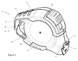
- the blade 16 is wound on the reel 14 and the distal end of the blade 16 is arranged to extend outwardly through the opening 22 provided in the housing 12 as shown, for example, in Figure 1 .
- the blade 16 is constructed of a ribbon of sheet metal that is shaped during the manufacturing to have a normal or memory configuration that has a generally arcuate or concavo-convex transverse cross-section. In one embodiment, the thickness of the elongated blade 16 may be within the range of 0.0045 to 0.0063 inches.
- the blade 16 also comprises a paint layer 17 provided on the metal base material.
- the fixed arm 21 projects rearwardly and comprises a first portion 27 which projects rearwardly and a second portion 29 connected to the first portion which extends in a downwardly direction substantially perpendicular to the rearward direction.
- Figure 5 shows brackets depicting the length of the first portion 27 and the second portion 29 of the fixed arm.
- the fixed arm 21 provides a hook-like structure which is fixed with respect to the rest of the tape measure which means that objects can be easily threaded thereon. If the fixed arm was moveable, the objects such as belt loops could slip off before the clip assembly 19 as placed in the closed position.
- the fixed arm 21 can be any suitable shape in order to provide a hook-like structure.
- the first portion 27 and the second portion 29 form a dog leg arrangement for the fixed arm which defines a space 31 between the housing 12 and the inward face 33 of the second portion 29 facing the housing.
- the space 31 is enclosed when the sprung arm 23 abuts against the distal end 25 of the fixed arm 21.
- the sprung arm 23 is narrower in width than the fixed arm 21 and the recess 38 prevents the sprung arm 23 being dislodged from abutment with the fixed arm 21 due to a sideways force.
- the sprung arm 23 is pivotally mounted on the housing 12 at pivot point 36.
- the sprung arm 23 is arranged to pivot about the pivot point 36 between the closed and open positions.
- the sprung arm 23 is arranged to move between a closed position when the sprung arm is in abutment with the distal end 25 of the fixed arm 21 and an open position when the sprung arm 23 is adjacent the peripheral wall 48, 50 of the housing 12.
- the space 31 is no longer enclosed and the objects can be inserted into the space 31 via open mouth 53 revealed by the sprung arm 23 moving out of the way.
- the sprung arm 23 is biased to the closed position.
- the sprung arm 23 is moved from the closed position to the open position by exerting a force on the outside of the sprung arm and pressing it towards the housing 12.
- the sprung arm 23 can be slidably mounted on the housing 12. The slidably mounted sprung arm 23 retracts into a recess in the housing (not shown).
- the sprung arm 23 as shown in Figures 1 , 5 and 6 is a flat, planar element.
- the sprung arm 23 comprises a dog leg structure, but the sprung arm 23 in other embodiments can be flat.
- the sprung arm 23 is typically constructed from a metal material so that the sprung arm 23 is more durable and less prone to wear.
- the sprung arm 23 is biased with a coil spring 41 as shown in Figure 6 .
- the coil spring 23 can be replaced with any biasing means suitable for biasing the sprung arm 23 such as a leaf spring or a resilient rubber element.
- the clip assembly 19 will automatically close the sprung arm 23 around an object. This means fastening the tape measure 10 to an object can be completed with one hand in a single motion. The sprung arm 23 will snap shut with an audible click. This means that the user knows when the tape measure 10 has been attached to an object, say a belt loop, without even looking at the tape measure.
- the release mechanism of the clip assembly is simple and easily accessible and means the user can release the tape measure using gloved hands. In this way the user can retract the tape measure and attach the tape measure 10 to an object such as a belt loop all with one hand.
Landscapes
- Physics & Mathematics (AREA)
- General Physics & Mathematics (AREA)
- Tape Measures (AREA)
Priority Applications (3)
| Application Number | Priority Date | Filing Date | Title |
|---|---|---|---|
| EP14172209.0A EP2955476A1 (de) | 2014-06-12 | 2014-06-12 | Bandmaßanordnung |
| TW104119171A TW201608209A (zh) | 2014-06-12 | 2015-06-12 | 捲尺總成 |
| CN201510324465.7A CN105318795A (zh) | 2014-06-12 | 2015-06-12 | 卷尺组件 |
Applications Claiming Priority (1)
| Application Number | Priority Date | Filing Date | Title |
|---|---|---|---|
| EP14172209.0A EP2955476A1 (de) | 2014-06-12 | 2014-06-12 | Bandmaßanordnung |
Publications (1)
| Publication Number | Publication Date |
|---|---|
| EP2955476A1 true EP2955476A1 (de) | 2015-12-16 |
Family
ID=50933046
Family Applications (1)
| Application Number | Title | Priority Date | Filing Date |
|---|---|---|---|
| EP14172209.0A Withdrawn EP2955476A1 (de) | 2014-06-12 | 2014-06-12 | Bandmaßanordnung |
Country Status (3)
| Country | Link |
|---|---|
| EP (1) | EP2955476A1 (de) |
| CN (1) | CN105318795A (de) |
| TW (1) | TW201608209A (de) |
Cited By (1)
| Publication number | Priority date | Publication date | Assignee | Title |
|---|---|---|---|---|
| WO2019195246A1 (en) * | 2018-04-02 | 2019-10-10 | Apex Brands, Inc. | Measuring tape with transverse locating aperture |
Families Citing this family (6)
| Publication number | Priority date | Publication date | Assignee | Title |
|---|---|---|---|---|
| US10054415B2 (en) | 2015-09-30 | 2018-08-21 | Milwaukee Electric Tool Corporation | Tape measure |
| CN109804219B (zh) | 2016-10-05 | 2021-12-31 | 米沃奇电动工具公司 | 具有紧凑的收回系统的卷尺 |
| US9874428B1 (en) | 2016-10-05 | 2018-01-23 | Milwaukee Electric Tool Corporation | Tape measure with compact retraction system |
| KR102236808B1 (ko) | 2017-03-22 | 2021-04-05 | 밀워키 일렉트릭 툴 코포레이션 | 테이프 리트랙션을 위한 유성 기어 구동부를 갖는 줄자 |
| US10836603B2 (en) | 2017-03-22 | 2020-11-17 | Milwaukee Electric Tool Corporation | Tape measure with epicyclic gear drive for tape retraction |
| CN118776414A (zh) * | 2019-06-14 | 2024-10-15 | 米沃奇电动工具公司 | 机动式卷尺 |
Citations (6)
| Publication number | Priority date | Publication date | Assignee | Title |
|---|---|---|---|---|
| WO1998038471A1 (en) * | 1997-02-27 | 1998-09-03 | Metrica S.P.A. | Withdrawable graduated tape measuring instrument including a safety device |
| US20050081303A1 (en) * | 2003-10-21 | 2005-04-21 | Edward Goldberg | Carabiner tool assembly |
| US20060042805A1 (en) * | 2004-08-26 | 2006-03-02 | Sandlin Tamara M | Tool holder |
| EP1873407A1 (de) * | 2006-06-26 | 2008-01-02 | Tony Christianson | Schnappverschlusskarabinerhaken |
| US7506456B2 (en) | 2006-09-19 | 2009-03-24 | Alltrade Tools Llc | Rule assembly |
| EP2573506A1 (de) * | 2011-09-21 | 2013-03-27 | Stanley Black & Decker, Inc. | Massband mit variabeler Beschichtungssdicke |
Family Cites Families (2)
| Publication number | Priority date | Publication date | Assignee | Title |
|---|---|---|---|---|
| KR100621155B1 (ko) * | 2004-05-12 | 2006-09-08 | 주식회사코메론 | 손가락 보호용 줄자 |
| CN201926386U (zh) * | 2010-12-31 | 2011-08-10 | 贺攀 | 一种便于携带的卷尺 |
-
2014
- 2014-06-12 EP EP14172209.0A patent/EP2955476A1/de not_active Withdrawn
-
2015
- 2015-06-12 TW TW104119171A patent/TW201608209A/zh unknown
- 2015-06-12 CN CN201510324465.7A patent/CN105318795A/zh active Pending
Patent Citations (7)
| Publication number | Priority date | Publication date | Assignee | Title |
|---|---|---|---|---|
| WO1998038471A1 (en) * | 1997-02-27 | 1998-09-03 | Metrica S.P.A. | Withdrawable graduated tape measuring instrument including a safety device |
| EP0970347A1 (de) | 1997-02-27 | 2000-01-12 | METRICA S.p.A. | Rollbandmass mit sicherheitsverriegelung |
| US20050081303A1 (en) * | 2003-10-21 | 2005-04-21 | Edward Goldberg | Carabiner tool assembly |
| US20060042805A1 (en) * | 2004-08-26 | 2006-03-02 | Sandlin Tamara M | Tool holder |
| EP1873407A1 (de) * | 2006-06-26 | 2008-01-02 | Tony Christianson | Schnappverschlusskarabinerhaken |
| US7506456B2 (en) | 2006-09-19 | 2009-03-24 | Alltrade Tools Llc | Rule assembly |
| EP2573506A1 (de) * | 2011-09-21 | 2013-03-27 | Stanley Black & Decker, Inc. | Massband mit variabeler Beschichtungssdicke |
Cited By (4)
| Publication number | Priority date | Publication date | Assignee | Title |
|---|---|---|---|---|
| WO2019195246A1 (en) * | 2018-04-02 | 2019-10-10 | Apex Brands, Inc. | Measuring tape with transverse locating aperture |
| US11378375B2 (en) | 2018-04-02 | 2022-07-05 | Apex Brands, Inc | Measuring tape with transverse locating aperture |
| CN115096158A (zh) * | 2018-04-02 | 2022-09-23 | 艾沛克斯品牌公司 | 一种具有横向定位孔的卷尺 |
| US11913779B2 (en) | 2018-04-02 | 2024-02-27 | Apex Brands, Inc. | Measuring tape with transverse locating aperture |
Also Published As
| Publication number | Publication date |
|---|---|
| TW201608209A (zh) | 2016-03-01 |
| CN105318795A (zh) | 2016-02-10 |
Similar Documents
| Publication | Publication Date | Title |
|---|---|---|
| EP2955476A1 (de) | Bandmaßanordnung | |
| US6996915B2 (en) | Tape measure apparatus which can be used as a marking gauge and/or compass | |
| US6497050B1 (en) | Tape measure apparatus which can be used as a marking gauge and/or compass | |
| US8683710B2 (en) | Tape measure tool with lanyard | |
| US5842284A (en) | Tape measure with finger grip and finger guard guide | |
| US9851193B2 (en) | Tape measure apparatus with a rotating and sliding catch | |
| US4103426A (en) | Apparatus for converting a measuring tape to a compass | |
| US5349760A (en) | Measuring and cutting tool | |
| EP1725828B1 (de) | Massband mit zugang zum gespulten blatt | |
| EP2784437B1 (de) | Rollmaßband-Verriegelungssystem | |
| AU2004201113B2 (en) | Retractable rule assembly with improved blade opening | |
| US6796052B1 (en) | Structure for the endpiece of tape rule | |
| EP1974177B1 (de) | Massbänder | |
| CA2857462C (en) | Improved tape measure apparatus with a rotating and sliding catch | |
| CA2983825C (en) | Tape measure device and attachment for measuring and cutting drywall | |
| US20040211080A1 (en) | Structure for the endpiece of tape rule | |
| US8819950B1 (en) | Releasable tip for a chalk line reel set | |
| US9470500B2 (en) | Tape measure apparatus with a rotating and sliding catch | |
| US20160288346A1 (en) | Razor Blade Holder/Scrapper |
Legal Events
| Date | Code | Title | Description |
|---|---|---|---|
| PUAI | Public reference made under article 153(3) epc to a published international application that has entered the european phase |
Free format text: ORIGINAL CODE: 0009012 |
|
| AK | Designated contracting states |
Kind code of ref document: A1 Designated state(s): AL AT BE BG CH CY CZ DE DK EE ES FI FR GB GR HR HU IE IS IT LI LT LU LV MC MK MT NL NO PL PT RO RS SE SI SK SM TR |
|
| AX | Request for extension of the european patent |
Extension state: BA ME |
|
| 17P | Request for examination filed |
Effective date: 20160609 |
|
| RBV | Designated contracting states (corrected) |
Designated state(s): AL AT BE BG CH CY CZ DE DK EE ES FI FR GB GR HR HU IE IS IT LI LT LU LV MC MK MT NL NO PL PT RO RS SE SI SK SM TR |
|
| 17Q | First examination report despatched |
Effective date: 20180711 |
|
| STAA | Information on the status of an ep patent application or granted ep patent |
Free format text: STATUS: THE APPLICATION IS DEEMED TO BE WITHDRAWN |
|
| 18D | Application deemed to be withdrawn |
Effective date: 20190122 |