EP4450139A2 - Umwandelbares spielzeug - Google Patents
Umwandelbares spielzeug Download PDFInfo
- Publication number
- EP4450139A2 EP4450139A2 EP24193404.1A EP24193404A EP4450139A2 EP 4450139 A2 EP4450139 A2 EP 4450139A2 EP 24193404 A EP24193404 A EP 24193404A EP 4450139 A2 EP4450139 A2 EP 4450139A2
- Authority
- EP
- European Patent Office
- Prior art keywords
- toy
- movable
- latch
- movable housing
- housing
- Prior art date
- Legal status (The legal status is an assumption and is not a legal conclusion. Google has not performed a legal analysis and makes no representation as to the accuracy of the status listed.)
- Pending
Links
Images


Classifications
-
- A—HUMAN NECESSITIES
- A63—SPORTS; GAMES; AMUSEMENTS
- A63H—TOYS, e.g. TOPS, DOLLS, HOOPS OR BUILDING BLOCKS
- A63H3/00—Dolls
- A63H3/04—Dolls with deformable framework
-
- A—HUMAN NECESSITIES
- A63—SPORTS; GAMES; AMUSEMENTS
- A63H—TOYS, e.g. TOPS, DOLLS, HOOPS OR BUILDING BLOCKS
- A63H33/00—Other toys
- A63H33/003—Convertible toys, e.g. robots convertible into rockets or vehicles convertible into planes
-
- A—HUMAN NECESSITIES
- A63—SPORTS; GAMES; AMUSEMENTS
- A63H—TOYS, e.g. TOPS, DOLLS, HOOPS OR BUILDING BLOCKS
- A63H1/00—Tops
- A63H1/02—Tops with detachable winding devices
-
- A—HUMAN NECESSITIES
- A63—SPORTS; GAMES; AMUSEMENTS
- A63H—TOYS, e.g. TOPS, DOLLS, HOOPS OR BUILDING BLOCKS
- A63H1/00—Tops
- A63H1/20—Tops with figure-like features; with movable objects, especially figures
-
- A—HUMAN NECESSITIES
- A63—SPORTS; GAMES; AMUSEMENTS
- A63H—TOYS, e.g. TOPS, DOLLS, HOOPS OR BUILDING BLOCKS
- A63H13/00—Toy figures with self-moving parts, with or without movement of the toy as a whole
- A63H13/20—Toy roundabouts with moving figures; Toy models of fairs or the like, with moving figures
-
- A—HUMAN NECESSITIES
- A63—SPORTS; GAMES; AMUSEMENTS
- A63H—TOYS, e.g. TOPS, DOLLS, HOOPS OR BUILDING BLOCKS
- A63H3/00—Dolls
- A63H3/36—Details; Accessories
-
- A—HUMAN NECESSITIES
- A63—SPORTS; GAMES; AMUSEMENTS
- A63H—TOYS, e.g. TOPS, DOLLS, HOOPS OR BUILDING BLOCKS
- A63H3/00—Dolls
- A63H3/36—Details; Accessories
- A63H3/50—Frames, stands, or wheels for dolls or toy animals
-
- A—HUMAN NECESSITIES
- A63—SPORTS; GAMES; AMUSEMENTS
- A63H—TOYS, e.g. TOPS, DOLLS, HOOPS OR BUILDING BLOCKS
- A63H33/00—Other toys
- A63H33/18—Throwing or slinging toys, e.g. flying disc toys
-
- A—HUMAN NECESSITIES
- A63—SPORTS; GAMES; AMUSEMENTS
- A63H—TOYS, e.g. TOPS, DOLLS, HOOPS OR BUILDING BLOCKS
- A63H33/00—Other toys
- A63H33/26—Magnetic or electric toys
-
- A—HUMAN NECESSITIES
- A63—SPORTS; GAMES; AMUSEMENTS
- A63H—TOYS, e.g. TOPS, DOLLS, HOOPS OR BUILDING BLOCKS
- A63H7/00—Toy figures led or propelled by the user
Definitions
- the present disclosure relates generally to transformable toys capable of spinning like a spinning top.
- the disclosure relates to a transformable toy for use on a playing surface.
- transforming toys that can transform or change their shape between spherical-shaped and character-shaped positions.
- Chinese Patent Application No. 2011/47642 teaches a transformable toy that includes a spherical outer shell with a pivot member that allows it to be moved between a sphere and a figurine position.
- U.S. Patent No. 7,306,504 teaches a toy with a first movable, spherical member, a second movable, spherical member and a coupler positioned between and coupled to the first and second spherical movable members for transforming the toy from an open, figurine shape to a closed, spherical shape.
- a transformable toy comprising a top housing portion including a connector and at least one movable housing element that is movable between a retracted position and an expanded position, the at least one movable housing element being biased towards the expanded position and including a catch, the connector being separably connectable to one of a first bottom housing portion and a second bottom housing portion, each of the first bottom housing portion and the second bottom housing portion including a latch and an actuator connected to the latch, the latch being positioned within each of the first bottom housing portion and second bottom housing portion such that when the top housing portion is separably connected to one of the first and second bottom housing portions, and when the at least one movable housing element is moved to the retracted position, the latch engages the catch to retain the at least one movable housing element in the retracted position, the actuator being actuatable, when the at least one movable housing element is retained in the retracted position, to disengage the latch from the catch and release the at least one movable housing element, the
- a transformable toy comprising a top housing portion including a connector and at least one movable housing element that is movable between a retracted position and an expanded position, the at least one movable housing element being biased towards the expanded position and including a latch and an actuator connected to the latch, the connector being separably connectable to one of a first bottom housing portion and a second bottom housing portion, each of the first bottom housing portion and the second bottom housing portion including a catch positioned such that when the top housing portion is separably connected to one of the first and second bottom housing portions, and when the at least one movable housing element is moved to the retracted position, the latch engages the catch to retain the at least one movable housing element in the retracted position, the actuator being actuatable, when the at least one movable housing element is retained in the retracted position, to disengage the latch from the catch and release the at least one movable housing element, the second bottom housing portion including a driving element operably mounted within the second bottom housing
- a transformable toy for use on a playing surface, the transformable toy comprising a top housing portion including at least one movable housing element that is movable between a retracted position and an expanded position, the at least one movable housing element including a catch and being biased towards the expanded position, and a bottom housing portion separably connected to the top housing portion, and including a latch mounted therein and an actuator connected to the latch, the latch being positioned within the bottom housing such that when the at least one movable housing element is moved to the retracted position, the latch engages the catch to retain the at least one movable housing element in the retracted position, the actuator being actuatable when the at least one movable housing element is retained in the retracted position, to disengage the latch from the catch and release the at least one movable housing element, the top housing portion and the bottom housing portion each being shaped such that when the top housing portion and bottom housing portion are separably connected, and when the at least one movable housing element is
- a transformable toy for use on a toy playing surface, the transformable toy comprising a toy housing, a shaft assembly including a shaft rotatably mounted along a central axis of the toy housing and a flywheel mounted to the shaft, the shaft defining a spinning axis of the transformable toy and the flywheel being chargeable to drive a spinning motion of the transformable toy about the spinning axis such that the transformable toy is in a spinning orientation, an access aperture in the toy housing for charging the flywheel, at least one movable housing element that is movable between a retracted position and an expanded position, the at least one movable housing element including a catch and being biased towards the expanded position, a latch being positioned within the toy housing such that when the at least one movable housing element is moved to the retracted position, the latch engages the catch to retain the at least one movable housing element in the retracted position, and an actuator connected to the latch and including an interaction
- a spinning toy kit comprising a transformable toy including a toy housing which includes at least one movable housing element that is movable between a retracted position and an expanded position, the at least one movable housing element including a catch and being biased towards the expanded position, a latch being positioned within the transformable toy such that when the at least one movable housing element is moved to the retracted position, the latch engages the catch to retain the at least one movable housing element in the retracted position, and an actuator connected to the latch and being actuatable, when the at least one movable housing element is retained in the retracted position, to disengage the latch from the catch and release the at least one movable housing element.
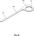
- the transformable toy including a shaft assembly including a shaft rotatably mounted within the toy housing and positioned along a central axis thereof, and a flywheel mounted to the shaft, the flywheel including a gear portion, an access aperture in the toy housing for accessing the flywheel, and ripcord cardholder including a cardholder body including a recess formed to receive and removably hold at least one playing card associated with the spinning toy, a ripcord member including a length of triangular teeth extending along at least a portion of at least one side thereof, the ripcord member being movably mounted to a side of the card holder body and being sized for insertion into the access aperture of the transformable toy such that the triangular teeth of the ripcord member engage with the gear portion of the flywheel for driving a spinning motion of the flywheel.
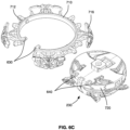
- a modular arena for use with a spinning toy that is driven to spin via a ripcord with a length of triangular teeth
- the modular arena comprising an inwardly disposed portion defining a surface for the spinning toy, at least one outer wall portions being interchangeably connectable to the inwardly disposed portion, and being shaped to at least partially surround the inwardly disposed portion, and at least one contact actuator connected to the at least one outer wall portion, the at least one contact actuator including a driving portion that is shaped to interface with the length of triangular teeth of the ripcord, and an actuating portion extending over a part of the surface for the spinning toy, the actuating portion being connected to the driving portion such that an interfacing of the ripcord and the driving portion actuates the actuating portion over the surface such that the actuating portion contacts the spinning toy and alters at least one of a spin speed and a direction of the spinning toy.
- a transformable toy that includes a top housing portion including a connector and at least one movable housing element that is movable between a retracted position and an expanded position.
- the at least one movable housing element is biased towards the expanded position and includes a catch.
- the connector is separably connectable to each of a first bottom housing portion and a second bottom housing portion.
- Each of the first bottom housing portion and the second bottom housing portion includes a latch and an actuator connected to the latch.
- the latch is positioned within each of the first bottom housing portion and second bottom housing portion such that when the top housing portion is separably connected to one of the first and second bottom housing portions, and when the at least one movable housing element is moved to the retracted position, the latch engages the catch to retain the at least one movable housing element in the retracted position.
- the actuator is actuatable to disengage the latch from the catch and release the at least one movable housing element.
- the second bottom housing portion includes a driving element operably mounted within the second bottom housing portion for driving a motion of the second bottom housing portion and the top housing portion along a support surface.
- the first bottom housing portion either is devoid of any driving element for driving motion of the first bottom housing portion, or includes a driving element that is different than the driving element of the second bottom housing portion and is operably mounted within the first bottom housing portion for driving a motion of the first bottom housing portion and the top housing portion along the support surface.
- a transformable toy in yet another aspect, includes a top housing portion including a connector and at least one movable housing element that is movable between a retracted position and an expanded position.
- the at least one movable housing element is biased towards the expanded position and includes a latch and an actuator connected to the latch.
- the connector is separably connectable to one of a first bottom housing portion and a second bottom housing portion.
- Each of the first bottom housing portion and the second bottom housing portion includes a catch positioned such that when the top housing portion is separably connected to one of the first and second bottom housing portions.
- the actuator is actuatable, when the at least one movable housing element is retained in the retracted position, to disengage the latch from the catch and release the at least one movable housing element.
- the second bottom housing portion includes a driving element operably mounted within the second bottom housing portion to drive a motion thereof.
- the latch includes a pivot member and a first magnetically responsive element provided on an end of the pivot member for interacting with a second magnetically responsive element, wherein at least one of the first magnetically responsive elements is a magnet, wherein an interaction of the first magnetically responsive element and the second magnetically responsive element drives an actuation of the actuator.
- the top housing portion and each of the first bottom housing portion and second bottom housing portion are individually shaped such that when the top housing portion and one of the first and second bottom housing portions are separably connected and when the at least one movable housing element is in the retracted position the transformable toy is rollable along the playing surface about at least one rotational axis of the transformable toy, and when the at least one movable housing element is in the expanded position, the at least one movable housing element inhibits rolling of the transformable toy about the at least one rotational axis.
- each of the first and second bottom housing portions is hemispherical; and wherein the shape of the top housing portion when the at least one movable housing element is in the retracted position is hemispherical.
- the second bottom housing portion includes a through-opening for accessing and driving a motion of the driving element.
- the driving element of the second bottom housing portion is a shaft assembly including a shaft rotatably mounted within the second bottom housing portion along a central axis of the second bottom housing portion; and a flywheel mounted to the shaft.
- a transformable toy for use on a playing surface.
- the transformable toy includes a top housing portion including at least one movable housing element that is movable between a retracted position and an expanded position.
- the at least one movable housing element includes a catch and being biased towards the expanded position.
- the transformable toy includes a bottom housing portion that is separably connected to the top housing portion.
- the bottom housing portion includes a latch mounted therein and an actuator connected to the latch.
- the latch is positioned within the bottom housing such that when the at least one movable housing element is moved to the retracted position. The latch engages the catch to retain the at least one movable housing element in the retracted position.
- the actuator is actuatable when the at least one movable housing element is retained in the retracted position to disengage the latch from the catch and release the at least one movable housing element.
- the top housing portion and the bottom housing portion each are shaped such that when the top housing portion and bottom housing portion are separably connected and when the at least one movable housing element is in the retracted position, the transformable toy is rollable along the playing surface about at least one rotational axis of the transformable toy, and when the at least one movable housing element is in the expanded position, the at least one movable housing element inhibits rolling of the transformable toy about the at least one rotational axis.
- the shape of the bottom housing portions is substantially hemispherical, and the shape of the top housing portion is substantially hemispherical when the at least one movable housing element is in the retracted position.
- the at least one movable housing element is at least one top movable housing element.
- the bottom housing portion further includes at least one bottom movable housing element that is movable between a retracted position and an exposed position, the at least one bottom movable housing element being biased towards the exposed position and being operatively connected to the latch such that when the latch engages the catch of the top movable housing element, the at least one bottom movable housing element is retained in the retracted position; wherein an actuation of actuator for disengaging the latch from the catch will also release the at least one bottom movable housing element.
- a transformable toy for use on a toy playing surface.
- the transformable toy includes a toy housing, a shaft assembly, an access aperture, at least one movable housing element, a latch, and an actuator.
- the shaft assembly includes a shaft rotatably mounted along a central axis of the toy housing and a flywheel mounted to the shaft.
- the shaft defines a spinning axis of the transformable toy and the flywheel is chargeable to drive a spinning motion of the transformable toy about the spinning axis such that the transformable toy is in a spinning orientation.
- the access aperture is for charging the flywheel.
- the at least one movable housing element is movable between a retracted position and an expanded position.
- the at least one movable housing element includes a catch and being biased towards the expanded position.
- the latch is positioned within the toy housing such that when the at least one movable housing element is moved to the retracted position.
- the latch engages the catch to retain the at least one movable housing element in the retracted position.
- the actuator is connected to the latch and includes an interaction element. The actuator is actuatable, when the at least one movable housing element is retained in the retracted position, to disengage the latch from the catch and release the at least one movable housing element.
- the actuator is positioned within the toy housing such that when the transformable toy is spinning at or below a set speed, the transformable toy will tip from the spinning orientation such that the interaction element of the actuator interacts with at least a portion of the toy playing surface and drives an actuation of the actuator.
- the shaft is rotatably mounted within the toy housing such that an end of the shaft extends through the toy housing to define a spin point on which the transformable toy spins about the spinning axis.
- the toy housing includes a weighted section that is disposed eccentrically about the spinning axis of the toy housing, the weighted section being relatively positioned within the toy housing such that when the transformable toy is spinning about the spinning axis at or below the set speed, the transformable toy will tip from the spinning orientation such that the spinning motion of the transformable toy is stopped, and such that the interaction element of the actuator interacts with the at least a portion of the toy playing surface.
- the toy housing includes a spin point formed on a bottom extent of the toy housing, the spin point being positioned on the toy housing such that it intersects a central axis of the transformable toy and that the central axis of the transformable toy defines the spinning axis of the transformable toy.
- the actuator includes a pivot member with free first and second ends, the pivot member being pivotally mounted within the toy housing, wherein the free first end of pivot member includes the latch and the free second end of the pivot member includes the interaction element.
- the interaction element is a magnet.
- the at least a portion of the toy playing surface is a magnetic portion of the toy playing surface.
- the actuator includes at least one movable weight that is movable between an inner radial position and an outer radial position relative to the spinning axis of the transformable toy, the at least one movable weight being connected within the toy housing such that when the transformable toy is spinning at or below the set speed the sliding weight will be in the inner radial position, and when the transformable toy is spinning above the set speed the at least one movable weight will be in the outer radial position.
- the latch will disengage from the catch and release the at least one movable housing element.
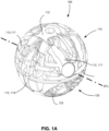
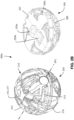
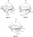
- a transformable toy 100 for use on a playing surface 102.
- the transformable toy 100 includes a top housing portion 110 and a bottom housing portion 120.
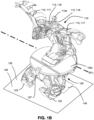
- the top housing portion 110 includes at least one movable housing element 112 that is movable between a retracted position (see Figure 1A and 1E ) and an expanded position (see Figures 1B and 1G ).
- the at least one movable housing element 112 includes a catch 112a and is biased towards the expanded position.
- the bottom housing portion 120 is separably connected to the top housing portion 110, and includes a latch 130 mounted therein, and an actuator 140 connected to the latch 130.
- the latch 130 is positioned within the bottom housing such that when the at least one movable housing element 112 is moved to the retracted position, the latch 130 engages the catch 112a to retain the at least one movable housing element 112 in the retracted position.
- the actuator 140 is actuatable when the at least one movable housing element 112 is retained in the retracted position, for disengaging the latch 130 from the catch 112a and releasing the at least one movable housing element 112.
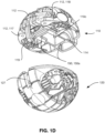
- the top housing portion 110 and the bottom housing portion 120 are each shaped to be separated (see Figure 1C and 1H ), and are also shaped such that when the top housing portion 110 and bottom housing portion 120 are separably connected, and when the at least one movable housing element 112 is in the retracted position, the transformable toy 100 is rollable along the playing surface 102 about at least one rotational axis (R1) of the transformable toy 100. Conversely, when the top housing portion 110 and bottom housing portion 120 are separably connected and the at least one movable housing element 112 is in the expanded position, the at least one movable housing element 112 inhibits rolling of the transformable toy 100 about the at least one rotational axis (R1).
- a shape of the bottom housing portion 120 is substantially hemispherical and a shape of the top housing portion 110 when the at least one movable housing element 112 is in the retracted position is substantially hemispherical.
- the movement of the at least one movable housing elements 112 from the expanded to the retracted position results in the shape of the top housing portion 110 becoming substantially hemispherical.
- the collective form of the transformable toy 100 is spherical (see Figure 1A and 1E ).
- a first embodiment of the transformable toy 100 includes the top housing portion 110 and bottom housing portion 120 which are separably connected together.
- the top housing portion 110 is hemispherical-shaped, having a curved top portion and a flat face formed as a bottom end thereof.
- the bottom housing portion 120 is also hemispherical-shaped, having a curved bottom portion and a generally flat face formed as a top end of the bottom housing portion 120.
- the transformable toy 100 includes the top housing portion 110, where the top housing portion 110 includes at least one movable housing element 112 that is movable between retracted and expanded positions.
- the top housing portion 110 includes a top housing body 114 to which the at least one movable housing element 112 is pivotably mounted.
- each of the at least one movable housing element 112 is mounted on a shaft 113 to define a pivot axis of the at least one movable housing element 112 for pivoting between the retracted and expanded positions.
- the at least one movable housing element 112 includes a spring 115 connected about the shaft 113 that defines the pivot axis.
- the spring 115 is positioned to bias the at least one movable housing element 112 towards the expanded position by applying a force which turns the at least one movable housing element 112 about the shaft 113.
- the spring 115 may be any suitable type of spring, such as a torsion spring that has a first end mounted to an element of the housing body 114 and a second end engaged with the at least one movable housing element 112.
- the at least one movable housing element 112 is at least one pair of movable housing elements that are pivotably connected to the top housing body 114 so as to pivot between retracted positions in which the pair of movable housing elements 112 are disposed close to the top housing body 114, and expanded positions where the movable housing elements 112 are disposed away from the top housing body 114 (see Figure 1B and 1H ).
- the hemispherical-shaped top housing portion 110 includes the top housing body 114, where a side region 114a of the top housing body 114 is formed with an at least partial dome shape, as if it were a section of a sphere that has been cut off.
- a hollow cavity 116 is defined within the top housing portion 110 when the at least one movable housing element 112 is in the retracted position.
- the at least one movable housing element 112 includes a central movable housing element 118.
- the central movable housing element 118 is mounted onto an upper central portion of the top housing body 114 such that the central housing element 118 is pivotable relative to the top housing body 114.
- the central movable housing element 118 of the exterior structure is an approximately circular, arc-shaped component that has a thin profile to define portions of an exterior surface of the top housing portion 110.
- An exterior surface of the at least one movable housing elements 112 constitutes one section of the spherical shape of the transformable toy 100.
- the at least one pair of movable housing elements 112 include lateral movable housing elements 117 that are pivotably mounted onto upper left and right lateral portions of the top housing body 114.
- the at least one movable housing element 112 also includes a horn element 119 that is pivotably mounted to the top housing body 114 for movement between a retracted and expanded position.
- the horn element 119 has an arc-shaped member with a sharply curved end. As shown in Figure 1A , when in its retracted position, the horn element 119 is disposed between the central movable housing elements 118 and is pivotably mounted to the top housing body 114.
- the horn element is connected to the central housing element 118 to pivot thereabout.
- the catch 112a of the top housing portion 110 that is retained by the latch 130 of the bottom housing portion 120 is defined by the sharply curved end of the horn element 119.
- the at least one movable housing element 112 is provided for transforming the transformable toy 100 from a rollable, spherical form (as presented in Figure 1A ) to a character form (as presented in Figure 1B ) that symbolizes a "dragon" or any other suitable character.
- the transformable toy 100 includes the bottom housing portion 120.
- the housing of the bottom housing portion 120 defines the spherical portion of the hemisphere, and a hollow cavity 126 is formed within the bottom housing portion 120.
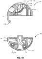
- the bottom housing portion 120 of the first embodiment of the transformable toy 100 includes the latch 130 mounted within the bottom housing portion 120, and an actuator 140.
- the latch 130 is movable to a latched position ( Figure 1E ) in which the latch 130 is positioned to retain the catch 112a of the at least one movable housing element 112 when the at least one movable housing element 112 is moved to the retracted position.
- the latch 130 is movable to a release position ( Figure 1F ) in which the latch 130 is positioned to release the catch 112a of the at least one movable housing element 112.
- the actuator 140 is movable to drive the latch 130 between the latched and release positions, in order to retain or release the catch 112a of the at least one movable housing element 112.
- an exterior surface 120a of the bottom housing portion 120 includes a through-hole 127.
- This through-hole 127 is positioned in the bottom housing portion 120 and extends into the hollow cavity 126 of the bottom housing portion such that when the at least one movable housing element 112 moves from the expanded to the retracted position, the catch 112a of the at least one movable housing element 112 is received in the through-hole 127 to engage with the latch 130 in the bottom housing portion 120.
- the catch 112a is formed as part of the horn element 119, and the through-hole 127 is positioned on a front side of the bottom housing portion 120 to receive the catch 112a.
- the top and bottom housing portions 110, 120 each include at least one connector 150, 152 that interfaces with the connector 150, 152 of the other housing portion for separably connecting the top and bottom housing portions 110, 120 together.
- the connector 152 of the bottom housing portion 120 includes a projection 152a that extends upwards from a flat face 120c of the bottom housing portion 120, and a flexible tab 152b.
- the flexible tab 152b includes a substantially planar portion that extends parallel to the flat face 120c of the bottom housing portion 120 and a tab portion that projects upwards from the planar portion.
- the connector 150 of the top housing portion 110 is a connecting aperture 150a that extends into the hollow cavity 116 of the top housing portion 110, where the connecting aperture 150a is sized and shaped to receive the projection 152a and flexible tab 152b from the bottom housing portion 120.
- the top housing portion 110 is tilted at an angle and a flat face 110c of the top housing portion 110 is advanced transversely along the flat face 120c of the bottom housing portion 120 until the flexible tab 152b is bent into and is received by the connecting aperture 150a.
- the top housing portion 110 is tilted down such that the projection 152a is received in the connecting aperture 150a of the top housing portion 110.
- the top and bottom housing portions 110, 120 are brought together until the flat faces 110c, 120c of each housing portion are in solid contact.
- the flexible tab 152b inhibits the separation of the flat faces 110c, 120c of the top and bottom housing portions 110, 120, while the projection 152a prevents relative, side-to-side motion of the top housing portion 110 and bottom housing portion 120.
- the latch 130 and actuator 140 are both mounted on a pivot member 142.
- the pivot member 142 has first and second free ends 142a, 142b, and is pivotally mounted within the hollow cavity 126 of the bottom housing portion 120 to pivot relative to the bottom housing portion 120.
- the latch 130 is mounted at the first free end 142a of the pivot member 142, and the actuator 140 is mounted at the second free end 142b.
- the pivot member 142 is mounted on a shaft 143 to define a pivot axis of the pivot member 142.
- the pivot member 142 is pivotable about the pivot axis between a latched position shown in Figure 1E and a release position shown in Figure 1F .
- the pivot member 142 includes a spring 199 connected about the shaft 143 that defines the pivot axis.
- the spring 199 is positioned to bias the pivot member 142 towards the latched position by applying a force which turns the pivot member 142 about the shaft 143.
- the spring 199 may be any suitable type of spring, such as a torsion spring that has a first end mounted to an element of the bottom housing portion 120 and a second end engaged with the pivot member 142.
- the actuator 140 includes an interaction element 144, which is positioned to interact with an object that is external to the transformable toy 100 in order to drive movement of the latch 130.
- the interaction member is a first magnetically responsive element 145 that is positioned for interacting with a second magnetically responsive member 146 ( Figure 1B ) that is external to the transformable toy 100.
- a magnetically responsive member is a member that is urged to move, either by attraction or repulsion, by the presence of a magnetic field.
- a magnetically responsive member may be any suitable type of member, such as, for example, a magnet, or a ferro-magnetic member (such as a piece of carbon steel).
- At least one of the first and second magnetically responsive elements is a magnet, while the other of the first and second magnetically responsive elements is an element that is attracted to a magnet, such as another magnet, or an element that is ferromagnetic, paramagnetic or that exhibits any other suitable type of magnetism.
- At least one of the first and second magnetically responsive elements 145, 146 is a magnet.
- the other of the first and second magnetically responsive elements 145, 146 may be a magnet or may be some other type of magnetically responsive member such as the aforementioned piece of carbon steel.
- Interaction of the first magnetically responsive element 145 with the second magnetically responsive member 146 causes actuation of the actuator 140.
- the first magnetically responsive element 145 is positioned within sufficiently close proximity to the second magnetically responsive element 146 to cause actuation of the first magnetically responsive element 145, moving the first magnetically responsive element 145 from the position shown at 198a (in broken lines), to the position shown at 198b (in solid lines).
- the first magnetically responsive element 145 is a magnet and the second magnetically responsive element 146 is a strip of a magnetizable steel, such as carbon steel, that is included in a toy support member 103 ( Figure 1B ).
- the toy support member 103 may be a card or the like, or any other suitable support member, and defines the toy playing surface 102.
- the magnet is mounted on a lower section of the second free end 142b of the pivot member 142, while the other end of the pivot member 142 has the latch 130 mounted thereon. The magnet is mounted such that it projects slightly out from the aperture in which it is retained, and faces substantially downwards on the pivot member 142.
- the bottom housing portion 120 may include a thin-wall portion 125a.
- the thin-wall portion 125a is formed on a lower section of the hemispherical form of the bottom housing portion 120.
- the thin-wall portion 125a is shaped with a thickness such that the second magnetically responsive member 146 can act on, and attract the first magnetically responsive element 145 of the pivot member 142 through the thin-wall portion 125a.
- the thin-wall portion 125a is positioned along the bottom housing portion 120 such that when the pivot member 142 is in an unactuated position, the first magnetically responsive element 145 is spaced apart from the thin-wall portion 125a, and when the second magnetically responsive element is brought into proximity to the thin-wall portion 125a on the outside of the transformable toy 100, the first magnetically responsive element 145 is attracted to the second magnetically responsive element 146 and moves towards it, driving the pivot member 142 to move from the unactuated to an actuated position, thereby moving the latch 130 from the latching position to the release position.
- the bottom housing portion 120 includes an aperture in place of the thin-wall portion 125a.
- the first magnetically responsive element 145 of the pivot member 142 will be attracted to the second magnetically responsive element 146 without there being any part of the bottom housing portion 120 between them.
- the first magnetically responsive element 145 to be positioned closer to the second magnetically responsive element 146 when the pivot member 142 is in the unactuated position, then would be possible if the wall of the bottom housing portion 120 did not have the thin-wall portion 125a or the aperture. This may, in some embodiments, increase the distance that the transformable toy 100 can be from the second magnetically responsive element 146 while still applying a sufficiently strong attractive force on the second magnetically responsive element 146 to drive movement of the first magnetically responsive element 145 thereby moving the latch 130 to the release position.
- the "transforming" features of the transformable toy 100 are defined in both the top housing portion 110 and the bottom housing portion 120.
- the at least one movable housing element 112 defines at least one top movable housing element.
- the bottom housing portion 120 includes at least one bottom movable housing element 123 that is movable between a retracted position (see Figure 1A ) and an expanded position (see Figure 1B ).
- the at least one bottom movable housing element 123 is biased towards the expanded position.
- the latch 130 may be operatively connected to the at least one bottom movable housing element 123 in some embodiments, in the sense that.
- the latch 130 when the latch 130 engages the catch 112a of the top movable housing portion 112, the latch 130 also retains the at least one bottom movable housing element 123 in the retracted position.
- the actuator 140 may be said to be actuatable to disengage the latch 130 from the catch 112a, which in turn releases the at least one bottom movable housing element 123.
- the bottom housing portion 120 includes a bottom housing body 121 to which the at least one bottom movable housing element 123 is pivotably mounted.
- An exterior surface of the bottom housing body 121 has a slight dome shape, as if it were a section of a sphere that has been cut off, and the exterior surface thereof constitutes one section of the spherical shape.
- the at least one bottom movable housing element 123 is two bottom movable housing elements that are pivotably mounted on opposing sides of the bottom housing body 121. In this way, the two bottom movable housing elements 123 form "leg" components of the character represented by the transformable toy 100, when the elements 123 are in an expanded position.
- the at least one bottom movable housing element 123 may be biased towards the exposed position by a spring 179.
- the spring 179 may be any suitable type of spring such as a torsion spring mounted about a shaft 177 that defines a pivot axis of the at least one bottom movable housing element 123.
- the spring 179 is positioned to bias the at least one bottom movable housing element 123 towards the exposed position by applying a force which pivots the at least bottom movable housing element 123 about the shaft 177 towards the exposed position.
- the bottom movable housing elements 123 may push the transformable toy 100 so as to space the first magnetically responsive element 145 away from the second magnetically responsive element 146, as shown in Figure 1G .
- the transformable toy 100 may be positioned such that the first magnetically responsive element 145 is sufficiently spaced apart from the second magnetically responsive element 146 that the card 103 is not magnetically adhered to the transformable toy 100.
- this may permit the transformable toy 100 to be picked up by the user without the card 103 adhering to it due to magnetic attraction.
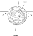
- the transformable toy 200a, 200b, 400, 500 is formed to be spun via a flywheel or similar driving element, about a spinning axis S1 of the transformable toy 200a, 200b, 400, 500, on a playing surface 300.
- the transformable toy 200a, 200b, 400, 500 is driven to spin about the spinning axis S1
- the transformable toy 200a, 200b, 400, 500 can be said to be in a spinning orientation.
- This spinning orientation can be defined where the transformable toy 200a, 200b, 400, 500 is spinning in an upright position such that the spinning axis S1 is substantially vertical (see Figures 3A and 3E ).
- the angular momentum of the transformable toy 200a, 200b, 400, 500 decreases, and a rate of precession of the toys spinning axis (S1) will increase, thereby causing the spinning axis S1 of the transformable toy 200a, 200b, 400, 500 to become progressively less vertical (see Figures 3B and 3C ).
- the spinning speed of the transformable toy 200a, 200b, 400, 500 will continue to decrease until the spinning speed of the transformable toy 200a, 200b, 400, 500 is at or below a set speed.
- the set speed is defined such that when the transformable toy 200a, 200b, 400, 500 is spinning about the spinning axis S1 at or below the set speed, the interaction element of the actuator will interact with at least a portion of the toy playing surface and drives an actuation of the actuator to disengage the latch from the catch
- the set speed is defined such that when the transformable toy 200a, 200b, 400, 500 is spinning about the spinning axis S1, at or below the set speed, the transformable toy 200a, 200b, 400, 500 will tip from the spinning orientation and the interaction element of the actuator will interact with at least a portion of the toy playing surface and drives an actuation of the actuator to disengage the latch from the catch.
- the spinning speed is defined such that the transformable toy 200a, 200b, 400, 500 will tip from the spinning orientation to such an extent that the spinning motion of the transformable toy 200a, 200b, 400, 500 is stopped.
- the set speed of the transformable toy 200a, 200b, 400, 500 can be further defined as the speed at which a component of the angular momentum of the transformable toy 200a, 200b, 400, 500 that is maintaining the transformable toy 200a, 200b, 400, 500 in the spinning orientation is overcome by a component of the weight of the transformable toy 200a, 200b, 400, 500 that is pulling the transformable toy 200a, 200b, 400, 500 out of the spinning orientation.
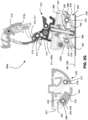
- the transformable toy is shown at 200a and includes a top housing portion 210 which is connectable to one of at least first and second bottom housing portions 220, 230.
- the top housing portion 210 of the transformable toy 200a includes a connector 211 and at least one movable housing element 212 that is movable between a retracted position (see Figures 2B , 2D and 2F ) and an expanded position (see Figures 2A , 2C and 2E ).
- top housing portion 210 shown in Figures 2A , 2E and 2F differs aesthetically from the top housing portion 210 shown in Figures 2B , 2C , 2D , 2G and 2H , however for the purposes of the description of the functional elements of these figures, all of Figures 2A-2H are to be considered the same as one another, and represent a single effective embodiment of the top housing portion 210.
- the at least one movable housing element 212 is biased towards the expanded position and includes a catch 212a.
- the connector 211 is formed to be separably connectable to one of a first bottom housing portion 220 and a second bottom housing portion, the second bottom housing portion 230 including a driving element 260 operably mounted within the second bottom housing portion 230 to drive a motion of the second bottom housing portion.
- the first bottom housing portion 220 and the second bottom housing portion 230 each include a latch 222, 232 and an actuator 224, 234 that is connected to the latch 222, 232.
- the latch 222, 232 is positioned such that when the top housing portion 210 is separably connected to one of the bottom housing portions (first and second bottom housing portions 220, 230) via the connector 211, and when the at least one movable housing element 212 is moved to the retracted position, the latch 222, 232 engages the catch 212a to retain the at least one movable housing element 212 in the retracted position.
- the second embodiment of the transformable toy 200a includes an actuator 224, 234 that is actuatable, when the at least one movable housing element 212 is retained in the retracted position, to disengage the latch 222, 232 from the catch 212a and release the at least one movable housing element 212.
- the top housing portion 210 and each of the first bottom housing portion 220 and second bottom housing portion 230 are individually shaped such that when the top housing portion 210 and one of the first and second bottom housing portions 220, 230 are separably connected, and when the at least one movable housing element 212 is in the retracted position, the transformable toy 200a is rollable along a playing surface 290 about at least one rotational axis of the transformable toy 200a. In this way, when the at least one movable housing element 212 of the top housing portion 210 is moved to the expanded position, the at least one movable housing element 212 inhibits rolling of the transformable toy 200a about the at least one rotational axis.
- each the first and second bottom housing portions 220, 230 is substantially hemispherical and the shape of the top housing portion 210 when the at least one movable housing element 212 is in the retracted position is substantially hemispherical.
- the movement of the at least one movable housing elements 212 from the expanded to the retracted position results in the shape of the top housing portion 210 becoming substantially hemispherical. In this way, when the hemispherical top portion is connected to the either the first or second bottom housing portions 220, 230, the collective form of the transformable toy 200a is substantially spherical.
- the transformable toy 200a includes a hemispherical top housing portion 210 and hemispherical first and second bottom housing portions 220, 230.
- the second embodiment of the transformable toy 200a includes a top housing portion 210, where the top housing portion 210 includes at least one movable housing element 212 that is movable between retracted and expanded positions.
- the top housing portion 210 includes a top housing body 214 to which the at least one movable housing element 212 is pivotably mounted.
- the at least one movable housing element 212 may be biased towards the expanded position by a spring 215.
- the spring 215 may be any suitable type of spring such as a torsion spring mounted about a shaft 213 that defines a pivot axis of the at least one movable housing element 212 and may be similar to the spring 115.
- the spring 215 is positioned to bias the at least one movable housing element 212 towards the expanded position by applying a force which pivots the at least one movable housing element 212 about the shaft 213 towards the expanded position.
- the at least one movable housing element 212 is one or more pairs of movable housing elements that are pivotably connected to the top housing body 214 so as to pivot between retracted positions in which the pairs of movable housing elements are disposed close to the top housing body 214, and expanded positions where the movable housing elements are disposed away from the top housing body 214.
- the hemispherical-shaped top housing portion 210 includes the top housing body 214, where a region 214a of the top housing body 214 is formed with an at least partial dome shape, as if it were a section of a sphere that has been cut off.
- a hollow cavity 216 is formed within the top housing portion 210.
- the at least one movable housing element 212 includes a central movable housing element 217. The central movable housing element 217 is mounted onto an upper central portion of the top housing body 214 such that the central housing element 217 is pivotable relative to the top housing body 214.
- the at least one movable housing element also includes lateral movable housing elements 218 that are pivotably mounted onto upper left and right lateral portions of the top housing body 214.
- the central movable housing element 217 has an exterior structure that is arc-shaped, and the central movable housing element 217 has a thin profile that defines portions of an exterior surface of the top housing portion 210.
- An exterior surface of the at least one movable housing element 212s constitute one section of the spherical shape of the transformable toy 200a provided in Figures 2B and 2D .
- the at least one movable housing element 212 also includes a horn element 219 that is pivotably mounted to either the central housing element 217 or the top housing body 214 for movement between the retracted and expanded positions.
- the horn element 219 has a roughly circular, arc-shape with a sharply curved end-portion. As shown in Figures 2B , 2D and 2F , when in its retracted position, the horn element 219 is disposed in a space that is defined between the lateral movable housing elements 218
- the catch 212a of the top housing portion 210 that is retained by the latch 222, 232 of the bottom housing portion is defined by the sharply curved end of the horn element 219.
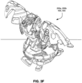
- the at least one movable housing element 212 is provided for transforming the transformable toy 200a from a rollable, spherical shape to a character shape as presented in Figures 2A to 2D .
- first and second bottom housing portions 220, 230 are each presented as the substantially hemispherical first and second bottom housing portions 220, 230, each of which include a hollow cavity 216, is formed therewithin.
- Each of the first and second bottom housing portions 220, 230 of this embodiment of the transformable toy 200a include the latch 222, 232 mounted within the bottom housing portion, and the actuator 224, 234 connected to the latch 222, 232.
- the latch 222, 232 is positioned to retain the catch 212a of the at least one movable housing element 212 when the at least one movable housing element 212 is moved to the retracted position. Together with the actuator 224, 234, the latch 222, 232 is moved to retain and release the catch 212a of the at least one movable housing element 212.
- an exterior surface of each of the first and second bottom housing portions 220, 230 include a through-hole 227, 237.
- the through-hole 227, 237 of each housing portion 220, 230 is positioned in each housing portion 220, 230 and is formed such that when the at least one movable housing element 212 moves from the expanded to the retracted position, the catch 212a of the at least one movable housing element 212 is received in the through-hole 227, 237 to engage with the latch 222, 232 in the bottom housing portion.
- the catch 212a is formed as part of the horn element 219, and the through-hole is positioned on a front side of the bottom housing portion to receive a portion of the horn element 219.
- each of the first and second bottom housing portions 220, 230 include a connecting element 252, 253 that corresponds to, and interfaces with, the connector 211 of the top housing portion 210 for connecting the top and one of the first and second bottom housing portions 220, 230.
- the top housing portion 210 can be separably coupled to either the first bottom housing portion 220 or second bottom housing portions 230.
- the connecting element 252, 253 of each of the first and second bottom housing portions 220, 230 includes a projection 252a, 253a that extends upwards from the flat face of the first or second bottom housing portion, and a flexible tab 252b, 253b.
- the flexible tab 252b, 253b of each bottom housing portion 220, 230 extends towards a back part of the first or second bottom housing portions 220, 230 and includes a substantially planar portion that rests parallel to a flat face of the first or second bottom housing portions and a tab portion that projects upwards from the substantially planar portion.
- the connector 211 of the top housing portion 210 is a connecting aperture 250a that extends into the hollow cavity 216 of the top housing portion 210 where the aperture is sized and shaped to receive the projection 252a, 253a and flexible tab 252b, 253b from the one of the first and second bottom housing portions 220, 230.
- the top 210 and bottom housing portion (220 or 230) are oriented such that a front part of a flat face of the top housing portion 210 is positioned atop a back part of the flat face 220c, 230c of the first or second bottom housing portions.
- the top housing portion 210 is then tilted at an angle and advanced transversely along the flat face 220c, 230c of the first or second bottom housing portions 220, 230 until the flexible tab 252b bends into and is received by the connecting aperture 250a.
- the top housing portion 210 is tilted down such that the projection 252a is received in the connecting aperture 250a of the top housing portion 210.
- the top and bottom housing portions (210 and 220 or 230) are brought together until the flat faces of each housing portion are in solid contact.
- the flexible tab 252b, 253b inhibits the separation of the flat faces of the top and bottom housing portions, while the projection 252a, 253a prevents relative, side-to-side motion of the top housing portion 210 and first or second bottom housing portions 220, 230.
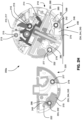
- the latch 222, 232 and actuator 224, 234 of at least one of the bottom housing portions 220, 230 is mounted on a pivot member 242 with free first and second ends, the pivot member 242 being pivotally mounted within the bottom housing portion within the hollow cavity 226 of the first or second bottom housing portions 220, 230 to pivot relative to the first or second bottom housing portions 220, 230.
- the free first end of pivot member 242 includes the latch 222, 232 and the free second end of the pivot member 242 includes the interaction element 244.
- the pivot member 242 is positioned in the interior of each of the first and second bottom housing portions 220, 230.
- the pivot member 242 has a first free end 242a at which the latch 222, 232 is mounted, and the second free end 242b at which the interaction element 244 is mounted.
- a hollow portion of the pivot member 242 is mounted about the shaft shown at 243 to define a pivot axis of the pivot member 242.
- the pivot member 242 is pivotable about the pivot axis in both a clockwise and anti-clockwise direction.
- the pivot member 242 is pivoted in a clockwise direction (in the views shown in Figures 2E and 2G ) to a latched position, and is moved in the anti-clockwise direction (in the views shown in Figures 2F and 2H ) to an unlatched or release position.
- the pivot member 242 may be biased towards the latched position by a spring 299 ( Figure 2E ).
- the spring 299 may be any suitable type of spring such as a torsion spring mounted about the shaft 243 and may be similar to the spring 199.
- the spring 299 is positioned to bias the pivot member 242 towards the latched position by applying a force which pivots the pivot member 242 about the shaft 243 towards the latched position.
- the interaction element 244 of the actuator 224, 234 is a first magnetically responsive element 245 that is positioned on the second free end 242b of the pivot member for interacting with a second magnetically responsive element 246, wherein at least one of the first and second magnetically responsive elements 245 and 246 is a magnet. In this way, an interaction of the first magnetically responsive element 245 with the second magnetically responsive element 246 generates an actuation of the actuator 224, 234.
- the first magnetically responsive element 245 may be a magnet and the second magnetically responsive element 246 is a strip of steel that is included in a toy support member 291 ( Figure 2F ).
- the toy support member 291 may be a card or the like, or any other suitable support member, and defines the toy playing surface 290.
- the magnet is mounted on a lower section of the second free end 242b of the pivot member 242, while the other end of the pivot member 242 has the latch 222, 232 mounted thereon. The magnet is mounted such that it projects slightly from the aperture in which it is held on the pivot member 242.
- At least one of the first and second bottom housing portions 220, 230 includes a thin-wall portion 270.
- the thin-wall portion 270 is formed on a lower section of the hemispherical form of the first and/or second bottom housing portion 220, 230.
- the thin-wall portion 270 is shaped with a thickness such that the second magnetically responsive element 246 can attract the magnet of the pivot member 242 through the thin-wall portion 270, thereby driving the pivot member 242 from the unactuated position to an actuated position and bringing the magnet closer to the thin-wall portion 270.
- At least one of the first of second bottom housing portions 220, 230 includes an aperture in place of the thin-wall portion 270.
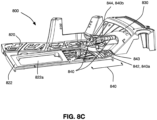
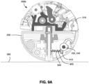
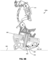
- the transformable toy 200a is a transformable toy 200b that includes the top housing portion 210, where the top housing portion is connectable, via the connector 211, to a second bottom housing portion 230 that includes an actuator 934 formed of at least one movable weight 910 that is movable between an inner radial position ( Figure 9B ) and an outer radial position ( Figure 9A ) relative to a central axis (C1) of the transformable toy 200b.
- the at least one movable weight 910 is connected within the second bottom housing portion 230 such that when the transformable toy 200a is spinning at or below the set speed, the movable weight 910 will be in the inner radial position, and when the transformable toy 200a is spinning above the set speed, the at least one movable weight 910 will be in the outer radial position.
- the latch 222, 232 will disengage from the catch 212a and release the at least one movable housing element 212.
- the movable weight 910 is slidably mounted along a shaft 920 that is fixed within the second bottom housing portion 230.
- the movable weight is biased towards the outer radial position along the shaft 920 by a biasing member 940.
- the biasing member 940 is a spring that is mounted around the shaft 920.
- the second bottom housing portion 230 also includes an access aperture 280 for accessing and driving a motion of the driving element 260.
- the access aperture 280 is sized for insertion therethrough of a charging element for driving a motion of the driving element 260 within the second bottom housing portion 230.
- At least one of the first bottom housing portion 220 or second bottom housing portion 230 of the transformable toy 200a include at least one bottom movable housing element 233.
- the at least one movable housing element 212 is at least one top movable housing element.
- the at least one bottom movable housing element 233 of the first or second bottom housing portions 220, 230 is formed to be movable between a retracted position and an exposed position.
- the at least one bottom movable housing element 233 being biased towards the exposed position and is operatively connected to the latch 222, 232 such that when the latch 232 engages the catch 212a of the top movable housing element, the at least one bottom movable housing element 233 is retained in the retracted position.
- the actuator 224, 234 of either the first or second bottom housing portions is also actuatable to disengage the latch 222, 232 from the catch 212a to release the at least one bottom movable housing element 233.
- the at least one bottom movable housing element 233 is mounted on a shaft 277 to define a pivot axis of the at least one bottom movable housing element 233 for pivoting between the retracted and exposed positions.
- the at least one bottom movable housing element 233 includes a spring 279 connected about the shaft 277 that defines the pivot axis. The spring 279 is positioned to bias the at least one bottom movable housing element 233 towards the exposed position by applying a force which turns the at least one bottom movable housing element 233 about the shaft 277.
- the spring 279 may be any suitable type of spring, such as a torsion spring that has an end engaged with the at least one bottom movable housing element 233.
- the first and second bottom housing portions 220, 230 each include a bottom housing body 220c, 230c to which the at least one bottom movable housing element 233 is pivotably mounted.
- An exterior surface of each of the bottom housing bodies 220c, 230c has a slight dome shape, as if it were a section of a sphere that has been cut off, and the exterior surface thereof constitutes one section of the spherical shape of the transformable toy 200a.
- the at least one bottom movable housing element 233 is two bottom movable housing elements 233 that are pivotably mounted on opposing sides of the bottom housing bodies 220c, 230c that form "leg" components of the character represented by the transformable toy 200a, when in the expanded position.
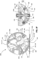
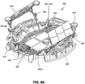
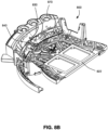
- the driving element 260 of the second bottom housing portion 230 is a shaft assembly 270 including a shaft 272 rotatably mounted within the second bottom housing portion 230, along a central axis of the second bottom housing portion, and a flywheel 276 mounted to the shaft 272.
- the shaft 272 is rotatably mounted inside the second bottom housing portion 230.
- a lower end of the shaft 272 rotatably engages a first bearing 273 in a lower side of the second bottom housing portion 230, and rotatably engages a second bearing 274 in an upper side of the second bottom housing portion 230.
- the flywheel 276 is mounted to the shaft 272 and rotates with the shaft 272.
- a gear element 278 is also mounted to the shaft 272 below the flywheel 276 such that the shaft 272, gear element 278 and flywheel 276 will rotate together when a force is applied to drive a rotation of the gear element 278 and shaft 272.
- the gear element 278 includes a plurality of triangular teeth that are sized to interface with triangular teeth of a charging element for imparting a force to the gear element 278.
- the shaft 272 is fixedly mounted inside the second bottom housing portion 230 so that it will not rotate, and the gear element 278 and flywheel 276 are rotatably coupled to the fixedly mounted shaft 272 such that the gear element 278 and flywheel 276 are coupled to rotate together about the shaft 272.
- gear element 278, flywheel 276 and shaft 272 are formed as an integral piece.
- the second bottom housing portion 230 includes a downward projection 252a formed on a bottom extent of the second bottom housing portion 230 which defines a spin point about which the second bottom housing portion 230 is driven to spin.
- the spin point is positioned such that as the transformable toy 200a is driven to spin about a spinning axis by the flywheel 276, the transformable toy 200a will spin about the spin point.
- the bearing 273 of the second bottom housing portion 230 extends through the second bottom housing portion 230 and defines the spin point of the transformable toy about which the transformable toy 200a will spin. In this way, the shaft and the central axis of the transformable toy 200a defines the spinning axis of the transformable toy 200a.
- the spin point is located at a bottommost extend of the hemispherical second bottom housing portion 230. In this way, the spin point intersects a central axis of the transformable toy 200a such that the central axis of the transformable toy 200a defines the spinning axis of the transformable toy 200a when spinning about the spin point.
- the spinning axis is defined along the shaft 272 of the shaft assembly 270.
- the shaft is rotatably mounted within the second bottom housing portion 230 such that an end of the shaft extends through the toy housing to define spin point on which the transformable toy 200a spins about the spinning axis.
- the transformable toy 200a includes a weighted section that is disposed eccentrically about the spinning axis S1.
- the weighted section is relatively positioned within the second bottom housing portion 230 such that when the transformable toy 200a (including the second bottom housing portion 230) is spinning about the spinning axis S1 at or below the set speed, the transformable toy 200a will tip somewhat, and may continue spinning.
- the transformable toy 200a is formed such that the weighted section is constituted by the latch 232 and actuator 234.
- the latch 232 and actuator 234 are positioned offset from the central, spinning axis S1 of the transformable toy 200a.
- the positioning of the latch and catch for retaining and releasing the at least one movable housing element is altered.
- the transformable toy includes a top housing portion that is connectable to one of at least first and second bottom housing portions.
- the top housing portion includes the connector and at least one movable housing element that is movable between a retracted position and an expanded position.
- the at least one movable housing element is biased towards the expanded position and includes a latch and an actuator connected to the latch.
- the connector of the top housing portion is separably connectable to one of a first bottom housing portion and a second bottom housing portion, where each of the first bottom housing portion and the second bottom housing portion include a catch that is positioned such that when the top housing portion is separably connected to one of the first and second bottom housing portions, and when the at least one movable housing element is moved to the retracted position, the latch engages the catch to retain the at least one movable housing element in the retracted position.
- the actuator is actuatable, when the at least one movable housing element is retained in the retracted position, to disengage the latch from the catch and release the at least one movable housing element.
- the second bottom housing portion includes a driving element operably mounted within the second bottom housing portion for driving a motion of the second bottom housing portion and the top housing portion along a support surface.
- the first bottom housing portion either is devoid of any driving element for driving motion of the first bottom housing portion, or includes a driving element that is different than the driving element of the second bottom housing portion and is operably mounted within the first bottom housing portion for driving a motion of the first bottom housing portion and the top housing portion along the support surface.
- the transformable toy is a transformable toy 400 for use on a toy playing surface 490, which comprises a toy housing 410, a shaft assembly 470 that includes a flywheel 476, at least one movable housing element 412, a latch 422 and an actuator 434.
- the toy housing 410 includes at least one movable housing element 412 that is movable between a retracted position (see Figure 4A ) and an expanded position (see Figure 4A ), the at least one movable housing element 412 including a catch 412a and being biased towards the expanded position, and the latch 422 being positioned within the toy housing 410 such that when the at least one movable housing element 412 is moved to the retracted position, the latch 422 engages the catch 412a to retain the at least one movable housing element 412 in the retracted position.
- the actuator 434 of the transformable toy 400 is connected to the latch 422 and includes an interaction element 444.
- the actuator 434 When the at least one movable housing element 412 is retained in the retracted position, the actuator 434 is actuatable to disengage the latch 422 from the catch 412a and release the at least one movable housing element 412.
- the actuator 434 is positioned within the toy housing 410 such that when the transformable toy 400 is spinning at or below a set speed, the interaction element 444 of the actuator 434 interacts with at least a portion of the toy playing surface 490 and drives an actuation of the actuator 434 to disengage the latch 422 member from the catch 412a.
- the transformable toy 400 also includes an access aperture 480 for charging the flywheel 476.
- the toy housing 410 and at least one movable housing element 412 are formed such that when the at least one movable housing element 412 is in the retracted position, a collective shape of the transformable toy 400 is substantially spherical.
- the toy housing 410 includes a housing body 414 to which the at least one movable housing element 412 is pivotably mounted.
- the at least one movable housing element 412 is pivotably mounted so as to pivot between a retracted position in which the at least one movable housing element 412 is disposed close to the housing body 414, and an expanded position where the at least one movable housing elements 412 is disposed away from the housing body 414.
- each of the at least one movable housing element 412 is mounted on a shaft 413 to define a pivot axis of the at least one movable housing element 412 for pivoting between the retracted and expanded positions.
- the at least one movable housing element 412 includes a spring 415 connected about the shaft 413 that defines the pivot axis.
- the spring 415 is positioned to bias the at least one movable housing element 412 towards the expanded position by applying a force which turns the at least one movable housing element 412 about the shaft 413.
- the spring 415 may be any suitable type of spring, such as a torsion spring that has a first end mounted to an element of the housing body 414 and a second end engaged with the at least one movable housing element 412.
- a hollow cavity 416 is formed within the housing body 414.
- the at least one movable housing element 412 includes central movable housing element 417 and lateral movable housing elements 418.
- the central movable housing element 417 is pivotably mounted onto an upper portion of the housing body 414 and the lateral movable housing elements 418 are pivotably mounted onto upper left and right lateral portions of the housing body 414 such that the housing elements are pivotable relative to the housing body 414.
- the at least one movable housing element 412 also includes a horn element 419 that is pivotably mounted to the housing body 414 for movement between a retracted and expanded position.
- the horn element 419 has an arc-shape with a sharply curved end-portion. As shown in Figure 4A , when in its retracted position, the horn element 419 is disposed in a space that is define between the central movable housing elements 417. The pivotable mounting of the horn element 419 to the top housing body 414 is about a first pivoting axis.
- the catch 412a of the at least one movable housing element 412 is defined by the sharply curved end of the horn element 419.
- the latch 422 and actuator 434 of the transformable toy 400 are formed on a pivot member 442 with free first and second ends 442a, 442b, the pivot member 442 being pivotally mounted within the toy housing 410 to pivot relative to the toy housing 410.
- the free first end 442a of pivot member 442 includes the latch 422 and the free second end 442b of the pivot member 442 includes an interaction element 444.
- the pivot member 442 is positioned in the interior of the toy housing 410, and the pivot member 442 is mounted about a pivot shaft 498 to define a pivot axis of the pivot member 442.
- the pivot member 442 is pivotable about the pivot axis in both a clockwise and anti-clockwise direction, to move the latch 422 between a latched position and an unlatched (or release) position, respectively.
- a spring 499 is connected about the pivot shaft 498 on which the pivot member 442 is mounted.
- the spring 499 is positioned to bias the pivot member 442 towards the latched position by applying a force which turns the pivot member 442 about the pivot shaft 498 towards the latched position.
- the interaction element 444 of the actuator 434 is a first magnetically responsive element 445 that is positioned on the free second end 442b of the pivot member for interacting with a second magnetically responsive element 446, wherein at least one of the first and second magnetically responsive elements 445, 446 is a magnet.
- the second magnetically responsive element 446 extends along or underneath at least a portion of the toy playing surface 490.
- the first magnetically responsive element 445 is mounted on a lower section of the free second end 442b of the pivot member 442, while the latch 422 is mounted at the free first end of the pivot member 442.
- the toy housing 410 may include a thin-wall portion 425. As described above in relation to the thin-wall portion 125a of the bottom housing portion 120, the thin-wall portion 425 is formed on a lower section of the spherical form of the toy housing 410.
- the thin-wall portion 425 is shaped with a thickness such that the second magnetically responsive element 446 can act on, and attract the magnet of the pivot member 442 through the thin-wall portion, thereby driving the pivot member 442 from the unactuated to an actuated position and brining the magnet closer to the thin-wall portion 425.
- the toy housing 410 includes an aperture in place of the thin-wall portion 425.
- the first magnetically responsive element 445 of the pivot member 442 will be attracted to the second magnetically responsive element 446 without having a structure between.
- the bearing 473 in the toy housing 410 extends through the toy housing 410 and projects through a bottom outer surface of the toy housing 410 to define a spin point formed on a bottom extent of the toy housing 410.
- the spin point is positioned such that as the transformable toy 400 is driven to spin about the spinning axis S1 by the flywheel 476, the transformable toy 400 will spin about the spin point.
- the shaft 472 is rotatably mounted within the second bottom housing portion such that an end of the shaft 472 extends through the toy housing 410 to define spin point on which the transformable toy 400 spins about the spinning axis S1.
- the transformable toy 400 includes a weighted section that is disposed eccentrically about the spinning axis S1.
- the weighted section is relatively positioned within the toy housing 410 such that when the transformable toy 400 is spinning about the spinning axis S1 at or below the set speed, the transformable toy 400 will tip from the spinning orientation such that the spinning motion of the transformable toy 400 is stopped, and such that the interaction element 444 of the actuator 434 is interacted with.
- the transformable toy 400 is formed such that the weighted section is constituted by the latch 422 and actuator 434 on the pivot member 442.
- the pivot member 442 including the latch 422 and actuator 434 are positioned offset from the central, spinning axis S1 of the transformable toy 400.
- the transformable toy 400 includes multiple housing portions (e.g., the top housing portion and the second bottom housing portion) and where one of the multiple housing portions includes a flywheel 476 or similar driving element (e.g., the flywheel 476 in the second bottom housing portion).
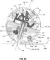
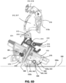
- the transformable toy is a transformable toy 500 that includes a toy housing 510 and a shaft 572 assembly with a flywheel 576 for imparting a spinning motion to the transformable toy 500.
- the toy 500 can be utilized as a spinning top as part of a spinning toy kit 501.
- spinning toy kit 501 is employed as part of a larger board and spinning top game, where the board and spinning top game includes playing cards associated with different game events and game characters, and where the spinning toy of the spinning toy kit 501 includes at least one spinning top that is associated with one or more playing cards of the game.
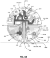
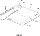
- the spinning toy kit 501 includes a transformable toy 500 that includes at least one movable housing element 512 that is movable between a retracted position (See Figure 5B , 5C ) and an expanded position (See Figure 5E ).
- the at least one movable housing element 512 includes a catch 512a and is biased towards the expanded position.
- the transformable toy 500 also includes a latch 522 that is positioned within the transformable toy 500 such that when the at least one movable housing element 512 is moved to the retracted position, the latch 522 engages the catch 512a to retain the at least one movable housing element 512 in the retracted position.
- the transformable toy 500 also includes an actuator 535 connected to the latch 522 and being actuatable, when the at least one movable housing element 512 is retained in the retracted position, to disengage the latch 522 from the catch 512a and release the at least one movable housing element 512.
- the at least one movable housing element 512 is mounted on a shaft 513 to define a pivot axis of the at least one movable housing element 512 for pivoting between the retracted and expanded positions.
- the at least one movable housing element 512 includes a spring 515 connected about the shaft 513 that defines the pivot axis.
- the spring 515 is positioned to bias the at least one movable housing element 512 towards the expanded position by applying a force which turns the at least one movable housing element 512 about the shaft 513
- the spring 515 may be any suitable type of spring, such as a torsion spring that has a first end mounted to an element of the toy housing 510 and a second end engaged with the at least one movable housing element 512.
- the transformable toy 500 includes a shaft assembly including a shaft 572 rotatably mounted within the toy housing 510 and positioned along a central axis C1 of the toy housing 510.
- the shaft 572 is rotatably mounted between two bearings 574 and 573.
- the shaft 572 assembly also includes a flywheel 576 mounted to the shaft 572, where the flywheel 576 includes a gear portion 578.
- the toy housing 510 also includes an access aperture 580 for accessing the flywheel of the shaft 572 assembly.
- the spinning toy kit 501 also includes a ripcord cardholder 560 including a cardholder body 562 with a card holder formed to receive and removably hold at least one playing card associated with the spinning toy, and a ripcord member 564 including a length of triangular teeth 565 extending along at least a portion of at least one side thereof.
- the ripcord member 564 is movably mounted to a side of the card holder body and is sized for insertion into the access aperture 580 of the transformable toy 500 such that the triangular teeth 565 of the ripcord member 564 engage with the gear portion 578 of the flywheel 576 for driving a spinning motion of the flywheel 576.
- the toy 500 includes a downward projection formed on a bottom extent of the bearing 573 which defines a spin point 569 about which the toy housing 510 is driven to spin.
- the spin point 569 is positioned such that as the transformable toy 500 is driven to spin about the central axis C1 by the flywheel 576, the transformable toy 500 will spin about the spin point 569.
- a hollow cavity 516 is formed within the toy housing 510.
- the at least one movable housing element 512 includes a central movable housing element 517 and lateral movable housing elements 518.
- the central movable housing element 517 is pivotably mounted onto an upper central portion of a housing body 514 of the toy housing 510 and the lateral movable housing elements 518 are pivotably mounted onto upper left and right lateral portions of the housing body 514 such that the housing elements are pivotable relative to the housing body.
- the at least one movable housing element 512 also includes a horn element 519 that is pivotably mounted to the top housing body 514 for movement between a retracted and expanded position.
- the horn element 519 has a roughly circular, arc-shape with a sharply curved end-portion. As shown in Figures 5B , when in its retracted position, the horn element 519 is disposed in a space that is define between the central movable housing elements 517. The pivotable mounting of the horn element 519 to the top housing body 514 is about a first pivoting axis.
- the catch 512a of the at least one movable housing element 512 that is retained by the latch 522 is defined by the sharply curved end of the horn element 519.
- a hollow portion of the pivot member 552 is mounted about a pivoting shaft to define a pivot axis of the pivot member 552.
- the pivot member 552 is pivotable about the pivot axis in both a clockwise and anti-clockwise direction.
- the pivot member 552 is pivoted in a clockwise direction (in the view shown in Figure 5B ) to a latched position, and is pivoted in the anti-clockwise direction to an unlatched or release position.
- the pivot member 552 includes a spring 599 connected about the shaft 572. The spring 599 is positioned to bias the pivot member 552 towards the latched position by applying a force which turns the pivot member 552 about the shaft 572 towards the latched position.
- the interaction element 555 of the actuator 535 is a first magnetically responsive element 545 that is positioned on the free second end 552b of the pivot member 552 for interacting with a second magnetically responsive element 546, wherein at least one of the first and second magnetically responsive elements 545 and 546 is a magnet. In this way, an interaction of the first magnetically responsive element 545 with a second magnetically responsive element drives an actuation of the actuator 535.
- the interaction element 555 is a first magnetically responsive element 545
- the first magnetically responsive element 545 is a solid magnet.
- the second magnetically responsive element is defined by at least a portion of the toy playing surface 590 that is a magnetic portion 590a of the toy playing surface 590.
- the magnet is mounted on a lower section of the free second end 552b of the pivot member 552, where the other end of the pivot member 552 includes the latch 522 hook. The magnet is mounted such that it is partially exposed on the pivot member 552.
- the access aperture 580 of the toy housing 510 extends between opposing sides of the toy housing 510.
- the access aperture 580 is positioned in a lower half of the toy housing 510 such that some of the triangular teeth 565 of the gear element 578 at least partially extending into a path defined along the length of the access aperture 580.
- a suitably sized ripcord member 564 with a length of triangular teeth 565 can be inserted along the access aperture 580 such that the teeth of the gear element 578 interface with the teeth of the charging element.
- the interfacing of the gear element 578 and charging element causes the gear element 578 and shaft 572 to rotate inside the toy housing.
- the flywheel will then rotate with the shaft 572 and from this rotation, can transfer a spinning motion to the toy housing 510 when the transformable toy 500 is placed on the playing surface 590.
- the ripcord member 564 has a length that is greater than a length of the access aperture 580 such that the ripcord member 564 can extend all the way through and beyond the access aperture 580 of the toy housing 510 when inserted into the access aperture 580. In this way, the ripcord member 564 provides an extended length of teeth 565 for applying a large torque to the gear element 578 of the shaft assembly 570.
- the ripcord member 564 of the ripcord cardholder 560 includes a connecting section 564a and a ripcord section 564b.
- the ripcord section 564b is a relatively long and thin extension of the ripcord member 564 that includes at least one set of triangular teeth extending along the ripcord section.
- the connecting section 564a of the ripcord member 564 includes a connecting aperture 563 extending through the connecting section 564a.
- the at least one set of triangular teeth is two sets of the triangular teeth 565 extending along opposing sides of the ripcord section 564b.
- the ripcord cardholder 560 includes a rectangular cardholder body 562.
- the cardholder body 562 includes a connecting projection 567 that extends outward from a surface of the cardholder body 562, where the projection 567 that is sized to receive in the connecting aperture 563 of the ripcord member 564.
- the connecting projection 567 of the cardholder body 562 is rotatably connected within the connecting aperture 563 of the ripcord member 564 such that the ripcord member 564 can be pivoted relative to the cardholder body 562.
- the cardholder body 562 also includes a substantially planar surface 562a and a plurality of tabs 566 that are slightly raised from the surface of the substantially planar surface 562a. In this way, a portion of the at least one playing card can be removably secured on the cardholder by sliding a portion of the at least one playing card between one of the plurality of tabs 566 and the substantially planar surface 562a.
- the toy can be utilized as a spinning top for spinning games.
- the spinning, transformable toy is used as a battling, spinning toy that is spun in proximity to other spinning toys, and contacts the other spinning toys.
- the transformable toy 200a, 200b, 400, 500 is defined as a battling, spinning toy 600.
- the battling, spinning toy 600 includes at least one removably connectable battling accessory for altering an appearance, shape, weight or spinning characteristic of the spinning toy 600.
- the at least one removably connectable battling accessory is one or more removably connectable adaptor rings 710.
- the removably connectable adaptor ring 710 includes a body member 712 with a hollow, inner circular form.
- the adaptor ring 710 includes a plurality of projections 716 that extend outward from the body member 712, and which are equally spaced around the circumference of the body member 712.
- FIGS. 7A, 7B and 7C show three embodiments of the projections 716 of the body member 712, including an adaptor ring 810 with a plurality of spherical, uneven projections 716, 720, an adaptor ring 810 with a plurality of wedge-shaped projections 716, 730, and an adaptor ring 810 with a plurality of "fin" shaped projections 716, 740.
- the toy housing is formed to include circumferential channel 720 sized to extend around at least half of the circumference of the transformable toy.
- the circumferential channel 720 is sized for receiving and removably holding an adaptor ring.
- the circumferential channel 720 is formed in the bottom housing portion and includes a pair of inwardly extending slots 640 positioned at each end of the circumferential channel 720.
- the adaptor rings 710 each includes pairs of corresponding tabs 630 on the ends thereof, where the inwardly extending slots 640 are sized to receive the tabs 630 of the adaptor ring 710 to prevent relative rotation of adaptor ring 710 about the transformable toy.
- the body member 712 of the adaptor rings 710 defines an opening 714 in the inner circular form of the adaptor ring 710 for inserting the adaptor ring 710 around one of the transformable toys, such as transformable toy 200a.
- adaptor ring 710 of the transformable toy 200a is formed to be resiliently flexible such that the inner circular form of the adaptor ring 710 can be bent around the transformable toy 200a when the opening 714 in the adaptor ring 710 is inserted around the transformable toy 200a.
- a modular arena 800 that includes one or more modular components.
- the modular arena 800 is formed for use in a battling spinning top game, where multiple battling, spinning toys are spun in proximity to one another within the arena, and where the spinning toys spin and contact each other as part of a battling game.
- the modular arena 800 is provided for use with at least one spinning toy that is driven to spin via a ripcord member 810 including a length of triangular teeth extending along at least one edge of the ripcord member 810.
- the modular arena 800 includes an inwardly disposed portion 820 that defines a playing surface 822 for the at least one spinning top.
- the modular arena 800 also includes at least one outer wall portion 830.
- the at least one of the outer wall portion 830 includes a contact actuator 840 mounted to the at least one outer wall portion 830.
- the contact actuator 840 includes a driving portion 842 that interfaces with the triangular teeth of the ripcord member 88, and an actuating portion 844 that extends over the playing surface 822 of the modular arena 800.
- the actuating portion 844 is connected to the driving portion 842 such that an interaction of the ripcord member 810 and the driving portion 842 drives an actuation of the actuating portion 844 between at least a first position and a second position about the surface of the modular arena.
- the actuating portion 844 is connected to the driving portion 842 such that an interfacing of the ripcord 810 and the driving portion 842 actuates the actuating portion 844 between the first position and the second position about the surface such that the actuating portion 844 contacts the spinning toy and alters at least one of a spin speed and a direction of the spinning toy.
- the ripcord member 810 the drives the at least one spinning top to spin is the ripcord member 564 of the ripcord cardholder 560 described previously.
- the at least one outer wall portion 830 is removably connectable to the inwardly disposed portion 820 of the modular arena 800 to at least partially surround a portion of the playing surface 822.
- the plurality of spinning tops are a plurality of the transformable toys as described herein, where the transformable toys can be any one or combinations of the various spinnable embodiments of the transformable toy as disclosed herein (including transformable toy 200a, transformable toy 200b, transformable toy 400 and transformable toy 500.
- the modular arena 800 includes one or more modular components that are removably connectable to and about the inwardly disposed portion 820 of the modular arena 800.
- the one or more modular components of then modular arena 800 includes at least one contact actuator 840, where the contact actuator 840 is operated by a ripcord member 810 that is also used for driving at least one of the plurality of spinning tops to spin.
- the modular arena 800 has a generally ovular form and includes the playing surface 822 for the plurality of spinning tops.
- the modular arena 800 includes a plurality of interchangeable wall portion 830s that are disposed around a plurality of sides of the playing surface 822.
- a wall portion 830 is positioned on four sides of the ovular playing surface 822 to provide a relatively continuous wall of the arena around the playing surface 822.
- Two of the wall portions 830 includes elevated card stands 850.
- the card holding stands includes a pair of support members 852 and a support platform 854 that is inclined at an angle over an edge of the playing surface 822.
- the support platform 854 is sized such that at least one playing card can be placed on, and supported by, the support platform 854.
- the two wall portions 830 that include the elevated card stands 850 also include a launch ramp for rolling at least one transformable toy onto the playing surface 822 of the modular arena 800.
- the launch ramps are each defined by a sloping recess that is integrally formed within the respective wall portions 830.
- the contact actuator 840 has the form of a three-arm spinning wheel.
- the spinning wheel includes a base portion 840a and a rotating top 840b that spins relative to the base portion 840a.
- the driving portion 842 of the contact actuator 840 is contained within the base portion 840a and the base portion 840a includes a through-aperture 843 for inserting a ripcord member 88 into the driving portion 842 of the contact actuator 840.
- the actuating portion 844 is defined by the rotating top 840b of the three-arm spinning wheel and includes three curved arms 840c extending radially outward from the rotating top 840b.
- the at least one wall portion 830 includes a holding recess 870.
- the holding recess 870 is sized and shaped to support a transformable toy when the transformable toy is not being used on the playing surface 822.
- At least one of the interchangeable wall portions 830 includes a contact actuator 840 as described above.
- the playing surface 822 includes a plurality of recesses 822a sized to removably hold an interchangeable section of the playing surface 822.
- the playing surface 822 also includes several upwardly projecting portions that are integrally formed with, and extend upward from, the playing surface 822. In use, an interchangeable section of the playing surface 822 is provided in each of the plurality of recesses 822a such that a substantially continuous playing surface 822 is formed.
- the interaction element in many embodiments, it has been shown for the interaction element to be a first magnetically responsive member, which interacts with a second magnetically responsive member that is external to the transformable toy.
- the interaction element could be some other type of member, such as a projection member on the pivot arm, which projects slightly downward from the immediately adjacent outer surface of the transformable toy, such that dropping the transformable toy would cause the projection member to hit whatever support surface the transformable toy is dropped on, which in turn drives the projection member upwardly into the body of the transformable toy.
- Driving the projection member upwardly may be the movement that, in turn, drives the pivot arm to pivot in such a way as to move the latch to the unlatched or release position.
- the transformable toy was positionable in a position in which it is a sphere, which permits the transformable toy to be rolled along a support surface.
- the transformable toy may be said to be in a rollable state, when it has the spherical shape.
- the transformable toy could be shaped differently than a sphere in the rollable state.
- the transformable toy could be shaped in a cylindrical form.
- the transformable toy could be shaped as a polyhedron with a sufficient number of faces and corners that it approximates a sphere and is rollable.
- the transformable toy in the rollable state could be shaped as a vehicle with wheels, and is therefore rollable.
Landscapes
- Toys (AREA)
Applications Claiming Priority (2)
| Application Number | Priority Date | Filing Date | Title |
|---|---|---|---|
| US17/887,383 US11712636B1 (en) | 2022-08-12 | 2022-08-12 | Transformable toy |
| EP22198408.1A EP4331697A1 (de) | 2022-08-12 | 2022-09-28 | Umwandelbares spielzeug |
Related Parent Applications (1)
| Application Number | Title | Priority Date | Filing Date |
|---|---|---|---|
| EP22198408.1A Division EP4331697A1 (de) | 2022-08-12 | 2022-09-28 | Umwandelbares spielzeug |
Publications (2)
| Publication Number | Publication Date |
|---|---|
| EP4450139A2 true EP4450139A2 (de) | 2024-10-23 |
| EP4450139A3 EP4450139A3 (de) | 2025-04-23 |
Family
ID=83505581
Family Applications (2)
| Application Number | Title | Priority Date | Filing Date |
|---|---|---|---|
| EP22198408.1A Pending EP4331697A1 (de) | 2022-08-12 | 2022-09-28 | Umwandelbares spielzeug |
| EP24193404.1A Pending EP4450139A3 (de) | 2022-08-12 | 2022-09-28 | Umwandelbares spielzeug |
Family Applications Before (1)
| Application Number | Title | Priority Date | Filing Date |
|---|---|---|---|
| EP22198408.1A Pending EP4331697A1 (de) | 2022-08-12 | 2022-09-28 | Umwandelbares spielzeug |
Country Status (9)
| Country | Link |
|---|---|
| US (1) | US11712636B1 (de) |
| EP (2) | EP4331697A1 (de) |
| JP (1) | JP7811537B2 (de) |
| KR (1) | KR20240022966A (de) |
| CN (3) | CN117618941A (de) |
| AU (1) | AU2022241517B2 (de) |
| CA (1) | CA3180169A1 (de) |
| IL (1) | IL304850A (de) |
| MX (2) | MX2025014782A (de) |
Families Citing this family (2)
| Publication number | Priority date | Publication date | Assignee | Title |
|---|---|---|---|---|
| USD1100069S1 (en) * | 2022-08-12 | 2025-10-28 | Spin Master Ltd. | Toy |
| KR20260031654A (ko) * | 2024-08-29 | 2026-03-09 | 주식회사 초이락컨텐츠컴퍼니 | 분리형 완구 |
Citations (3)
| Publication number | Priority date | Publication date | Assignee | Title |
|---|---|---|---|---|
| US7306504B2 (en) | 2004-07-12 | 2007-12-11 | Spin Master, Ltd. | Transformable toy |
| WO2011083313A1 (en) | 2010-01-07 | 2011-07-14 | Jkid Limited | A device with an enclosure and a flywheel |
| US9643095B2 (en) | 2013-07-11 | 2017-05-09 | Jong-Ill CHOI | Spinning top and spinning top play device using same |
Family Cites Families (160)
| Publication number | Priority date | Publication date | Assignee | Title |
|---|---|---|---|---|
| US152250A (en) | 1874-06-23 | Improvement in toys | ||
| US1387224A (en) | 1920-07-08 | 1921-08-09 | Ahler Edwin Arthur | Doll |
| US1557751A (en) | 1925-07-02 | 1925-10-20 | William M Parlett | Toy ball |
| US1610724A (en) | 1925-09-16 | 1926-12-14 | Samuel E Wilson | Multiple-face figure toy |
| GB374362A (en) | 1931-08-22 | 1932-06-09 | Carl Arnold | Means for spinning tops and for projecting flying toys of propeller form |
| US1985716A (en) | 1933-01-25 | 1934-12-25 | Essex Specialty Co Inc | Top |
| US2277672A (en) | 1941-02-14 | 1942-03-31 | Ralph A Stone | Toy |
| US2584789A (en) | 1950-03-07 | 1952-02-05 | Ibm | Automatic clamping device |
| US2584798A (en) | 1950-11-09 | 1952-02-05 | Goerditz Hans | Multiple faced doll |
| US2809062A (en) | 1954-09-13 | 1957-10-08 | Mainhardt Robert | Latch mechanism |
| US2968121A (en) | 1958-04-04 | 1961-01-17 | Glass | Toy |
| US2987852A (en) | 1958-05-26 | 1961-06-13 | Koch Fritz | Magnet toy |
| US3032921A (en) | 1960-03-29 | 1962-05-08 | Norman A Greene | Toy |
| US3095723A (en) | 1962-05-23 | 1963-07-02 | Harry F Mcknight | Lock and magnetic release device |
| US3166322A (en) | 1963-10-01 | 1965-01-19 | Branneman Leonard | Toy satellite system |
| US3401485A (en) | 1966-06-20 | 1968-09-17 | Leo Allen Goodrum Jr. | Magnetically activated toy dog |
| US3411237A (en) | 1966-11-03 | 1968-11-19 | Luxe Topper Corp De | Toy having magnetically actuatable appendage |
| US3520078A (en) | 1967-08-14 | 1970-07-14 | Klamer R B | Self-storing multicharactered toy |
| US3589059A (en) | 1969-12-08 | 1971-06-29 | Craig Vaughn Caswell | Rotary accelerator for toys |
| US3626961A (en) | 1970-03-11 | 1971-12-14 | Carlos Manuel Quinones | Magnetic hydrant lock |
| US3687452A (en) | 1970-12-02 | 1972-08-29 | Rayford L Thompson | Game ball |
| US3684292A (en) | 1970-12-03 | 1972-08-15 | Robert M Penrod | Puzzle toy |
| US3831986A (en) | 1972-08-09 | 1974-08-27 | S Kobayashi | Container having magnetic and latch fastening means |
| FR2314111A1 (fr) | 1975-06-11 | 1977-01-07 | Poulain Bernard | Dispositif magnetique de commande d'ouverture et de fermeture d'un couvercle de boite par des aimants |
| US4030239A (en) | 1976-01-29 | 1977-06-21 | Mattel, Inc. | Multiple face doll |
| US4132032A (en) | 1977-05-19 | 1979-01-02 | Triska Matej K | Toy with movable mouth |
| US4326235A (en) | 1979-01-26 | 1982-04-20 | Hopkins Norman K | Container |
| JPS6122624Y2 (de) | 1980-12-04 | 1986-07-07 | ||
| JPS57126289U (de) | 1981-01-31 | 1982-08-06 | ||
| JPS58126893U (ja) | 1982-02-23 | 1983-08-29 | 株式会社タイト− | 時計付電子ゲ−ム盤 |
| JPS58165881A (ja) | 1982-03-29 | 1983-09-30 | 株式会社 バンダイ | 玩具用腕時計 |
| AU551205B2 (en) | 1982-03-29 | 1986-04-17 | Bandai K.K. | Toy robot having timepiece in torso |
| JPS58179191U (ja) | 1982-05-25 | 1983-11-30 | 株式会社タカラ | 走行玩具 |
| GB2128489B (en) | 1982-10-12 | 1986-08-20 | Takara Co Ltd | Reconfigurable toy assembly |
| JPS5991984A (ja) | 1982-11-18 | 1984-05-26 | 山本 一郎 | 発音性くす玉 |
| GB2137105A (en) | 1983-03-30 | 1984-10-03 | Wiggs C C | Jack-in-the-box type toy |
| JPS6055491U (ja) | 1983-09-22 | 1985-04-18 | 株式会社タカラ | 組合せ変身玩具 |
| US4605381A (en) | 1983-12-29 | 1986-08-12 | Mattel, Inc. | Animated figure toy having a unitary, multiple-function spring |
| USD287258S (en) | 1984-01-31 | 1986-12-16 | Takara Co., Ltd. | Reconfigurable toy robot |
| JPS60128693U (ja) | 1984-02-03 | 1985-08-29 | 株式会社 タカラ | 形態変化玩具 |
| JPS60175292U (ja) | 1984-04-26 | 1985-11-20 | 株式会社トミー | 重力式回転機構 |
| JPS60253480A (ja) | 1984-05-30 | 1985-12-14 | 株式会社 タカラ | 形態変化玩具 |
| US4581904A (en) | 1984-12-20 | 1986-04-15 | Lehmann Roger W | Toy jewelry item with parts movable to a hidden position |
| JPH0234933Y2 (de) | 1984-12-28 | 1990-09-20 | ||
| JPS61159980A (ja) | 1984-12-29 | 1986-07-19 | 株式会社 増田屋コ−ポレ−シヨン | ロボットに変形できる文字表示ブロック玩具 |
| US4639232A (en) | 1985-03-01 | 1987-01-27 | Cheng Chung Wang | Toy having an envelope enclosing a moving mechanism |
| US4606618A (en) | 1985-05-23 | 1986-08-19 | Arco Industries | Optical device which is convertible to a toy robot |
| US4687459A (en) | 1985-11-06 | 1987-08-18 | Lockett G Jeffrey | Baby toy |
| CA1328474C (en) | 1985-11-07 | 1994-04-12 | Roger Conington Richards | Magnetically operated latch |
| US4773889A (en) | 1985-11-13 | 1988-09-27 | Marvin Glass & Associates | Wheel for a toy vehicle |
| JPH0421589Y2 (de) | 1985-12-27 | 1992-05-18 | ||
| JPS62155886A (ja) | 1985-12-28 | 1987-07-10 | 株式会社 タカラ | 跳び出しロボツト玩具 |
| US4696656A (en) | 1986-01-14 | 1987-09-29 | Mattel, Inc. | Reconfigurable toy |
| US4708687A (en) | 1986-02-07 | 1987-11-24 | Coleco Industries, Inc. | Rolling figure toy |
| US4817936A (en) | 1986-04-30 | 1989-04-04 | Takara Co., Ltd. | Spring-powered toy |
| US4698043A (en) | 1986-05-09 | 1987-10-06 | May-Curran Associates | Rolling egg toy |
| JPH06160Y2 (ja) | 1987-01-31 | 1994-01-05 | 株式会社タカラ | 訪問ごつこ玩具 |
| JPS6456087A (en) | 1987-08-20 | 1989-03-02 | Fumiaki Hayashi | Trigger control device for movable toy |
| JPH0161797U (de) | 1987-10-08 | 1989-04-19 | ||
| IT1219205B (it) | 1988-04-13 | 1990-05-03 | Ferrero Spa | Complesso di articolo di regalo e relativo involucro particolarmente per uova di cioccolato e simili prodotti alimentari cavi e procedimento di confezionamento |
| US5019010A (en) | 1988-04-15 | 1991-05-28 | Tomy Company, Ltd. | Transformable block toys |
| JPH01155497U (de) | 1988-04-15 | 1989-10-25 | ||
| US4874340A (en) | 1988-07-21 | 1989-10-17 | Smallwood Alice R | Combined amusement device and transport and storage pack |
| US5209345A (en) | 1990-04-24 | 1993-05-11 | Connie Haugabook | Combination storage and display unit |
| US5090935A (en) | 1990-12-17 | 1992-02-25 | Monson Chris S | Composite toy having interconnectable toy components |
| US5169156A (en) | 1991-02-13 | 1992-12-08 | Marchon, Inc. | Interactive action toy system |
| US5188405A (en) | 1991-03-06 | 1993-02-23 | Rev-A-Shelf, Inc. | Locking device for a latch |
| US5090938A (en) | 1991-03-27 | 1992-02-25 | Christopher Reynolds | Toy or other object alterable between two different shapes |
| US5169354A (en) | 1991-05-29 | 1992-12-08 | Fisher-Price, Inc. | Self-righting toy carousel |
| US5310378A (en) | 1992-06-01 | 1994-05-10 | Shannon Suel G | Transformable toy |
| JP3001886U (ja) | 1994-03-10 | 1994-09-06 | パイオニア精密株式会社 | 双眼鏡 |
| US5439408A (en) | 1994-04-26 | 1995-08-08 | Wilkinson; William T. | Remote controlled movable ball amusement device |
| GB9507167D0 (en) | 1995-04-06 | 1995-05-31 | Reilor Ltd | Improved pet door |
| US5855499A (en) | 1995-06-27 | 1999-01-05 | Kabushiki Kaisha Bandai | Packaging apparatus mounting a displayed article using a component of the article |
| WO1997045181A1 (en) | 1996-05-29 | 1997-12-04 | The All-Round Company Limited | Toy |
| JP3178705B2 (ja) | 1996-06-05 | 2001-06-25 | 株式会社タカラ | 作動玩具 |
| US6126507A (en) | 1997-03-13 | 2000-10-03 | Chameleon Products, Inc. | Reversible doll/hat |
| US5893791A (en) | 1997-06-02 | 1999-04-13 | Wilkinson; William T. | Remote controlled rolling toy |
| US5916007A (en) | 1997-07-08 | 1999-06-29 | Maxim; John G. | Magnetically tripped spring wound vehicles |
| US5902169A (en) | 1997-12-17 | 1999-05-11 | Dah Yang Toy Industrial Co., Ltd | Toy with changing facial expression |
| US6086449A (en) | 1998-01-15 | 2000-07-11 | Sharp; David F. | Cascading release fastener mechanism |
| US5893789A (en) | 1998-01-15 | 1999-04-13 | Wu; Li-Hsiung | Sphere toy |
| US6261146B1 (en) | 1998-05-08 | 2001-07-17 | Donald Spector | Package containing a shrunken body |
| US6089950A (en) | 1998-06-01 | 2000-07-18 | C. J. Associates, Ltd. | Toy figure with articulating joints |
| US6225885B1 (en) | 1999-01-08 | 2001-05-01 | Kuo Jung Lin | Switch device |
| US6592427B1 (en) | 1999-02-11 | 2003-07-15 | Learning Curve International, Inc. | Toy vehicle grain loader accessory |
| US6231346B1 (en) | 1999-12-06 | 2001-05-15 | Snubelgrass Interactive Ltd. | Interactive hatching egg |
| US6350171B1 (en) | 2000-02-03 | 2002-02-26 | Mattel, Inc. | Toy motorcycle configurable as a hovercycle |
| US6261149B1 (en) | 2000-04-20 | 2001-07-17 | Shane A. Moore | Reversible doll toy |
| US6773329B2 (en) | 2000-10-02 | 2004-08-10 | All Season Toys, Inc. | Amusement device including a thematic play set |
| GB2367766A (en) | 2000-10-16 | 2002-04-17 | Genie Toys Plc | Compressible toy figure and container. |
| CN2454000Y (zh) | 2000-11-29 | 2001-10-17 | 汤松广 | 一种玩具车 |
| DE10059712A1 (de) | 2000-12-01 | 2002-06-20 | Bosch Gmbh Robert | Handwerkzeugmaschine |
| US6682387B2 (en) | 2000-12-15 | 2004-01-27 | Silverlit Toys Manufactory, Ltd. | Interactive toys |
| US6592426B2 (en) | 2001-01-24 | 2003-07-15 | Thomas J. Mesch | Amusement device with flexible rubberized pop up figure |
| US6719606B1 (en) | 2001-07-11 | 2004-04-13 | Judy Mukensturm | Soft sculpture shellfish animal toy and accessories |
| KR200253111Y1 (ko) | 2001-07-19 | 2001-11-17 | 신억균 | 완구용 쌍안경 |
| JP2003062359A (ja) | 2001-08-21 | 2003-03-04 | Bandai Co Ltd | アクセサリー |
| US6530499B1 (en) | 2001-09-28 | 2003-03-11 | Thomas J. Coleman | Dispensing amusement device |
| JP4303458B2 (ja) * | 2001-09-28 | 2009-07-29 | 株式会社コナミデジタルエンタテインメント | ゲーム装置用プレイ・フィールド |
| JP4044333B2 (ja) | 2001-12-27 | 2008-02-06 | 株式会社センテクリエイションズ | 回転玩具 |
| JP3935364B2 (ja) | 2002-02-04 | 2007-06-20 | 株式会社バンダイナムコゲームス | 対象物供給装置 |
| US6572436B1 (en) | 2002-02-07 | 2003-06-03 | May Cheong Toy Products Factory Limited | Toy station |
| WO2004087274A2 (en) | 2003-03-25 | 2004-10-14 | Alise Shatoff | Food dispensing interlocking animal toy system |
| US6761612B1 (en) | 2003-05-02 | 2004-07-13 | Out Of The Box | Digital sports pop-up |
| GB0326232D0 (en) | 2003-11-11 | 2003-12-17 | Evolve Npd Ltd | Magnetic torque transfer system |
| US6752679B1 (en) | 2003-11-19 | 2004-06-22 | Hoe King Lui | Double doll figurine |
| JP3965384B2 (ja) * | 2003-12-19 | 2007-08-29 | 株式会社コナミデジタルエンタテインメント | 玩具用組立ユニット及び形態変形玩具 |
| ITTO20040796A1 (it) | 2004-11-12 | 2005-02-12 | Produzioni Editoriali Aprile Spa | Dispositivo di chiusura |
| TWI261489B (en) | 2004-12-22 | 2006-09-01 | Micro Star Int Co Ltd | Electronic device with variable configuration functions |
| JP3112866U (ja) | 2005-05-27 | 2005-08-25 | 株式会社タカラ | 球体発射玩具用球体 |
| JP4859206B2 (ja) | 2006-02-20 | 2012-01-25 | 株式会社セガ トイズ | 玩具 |
| CN201147642Y (zh) | 2007-09-28 | 2008-11-12 | 骆毅斯 | 一种变形弹丸玩具的变形结构 |
| CA2713351C (en) | 2008-01-10 | 2013-07-16 | Sega Toys Co., Ltd. | Toy |
| JP2009189521A (ja) | 2008-02-14 | 2009-08-27 | Tomy Co Ltd | 形態変化玩具 |
| JP4598839B2 (ja) | 2008-03-17 | 2010-12-15 | 株式会社タカラトミー | 形態変化玩具 |
| WO2009134750A1 (en) | 2008-04-28 | 2009-11-05 | Janssen Pharmaceutica Nv | Benzoimidazoles as prolyl hydroxylase inhibitors |
| KR200471569Y1 (ko) | 2010-01-28 | 2014-03-06 | 동아교재 주식회사 | 인출식 고형 마커 |
| US8777689B1 (en) | 2010-02-13 | 2014-07-15 | Phillip H. Neal | Environmentally-responsive transforming vehicles |
| AU2011277042B2 (en) | 2010-07-09 | 2014-09-04 | Jakks Pacific, Inc. | Core with finger indentation and formed to expel an object concealed therein |
| US20120309262A1 (en) | 2011-06-03 | 2012-12-06 | Daizo Uehara | Collectable helmet with interactive features |
| US8814629B2 (en) | 2011-06-21 | 2014-08-26 | Andrew Lewis Johnston | Non-rollable to rollable transforming toy |
| WO2013075045A1 (en) | 2011-11-17 | 2013-05-23 | Jakks Pacific, Inc. | Spinning toy with trigger actuated stop mechanism |
| KR101555865B1 (ko) | 2011-11-30 | 2015-09-25 | 광동 알파 애니메이션 앤드 컬처 컴퍼니 리미티드 | 분리 가능한 결합형 완구용 팽이 |
| KR101327305B1 (ko) | 2012-02-24 | 2013-11-11 | 최신규 | 변신 자동차 완구 및 이를 이용한 놀이 장치 |
| US9101847B2 (en) * | 2013-03-15 | 2015-08-11 | Bang Zoom Design, Ltd. | Shape changing apparatus and method |
| CN103405917B (zh) | 2013-07-29 | 2016-03-23 | 广东奥飞动漫文化股份有限公司 | 一种手持手动加速的悠悠球 |
| CN103405918B (zh) | 2013-07-29 | 2016-09-14 | 广东奥飞动漫文化股份有限公司 | 一种手持电动加速的悠悠球 |
| CN103599636B (zh) | 2013-11-21 | 2016-02-03 | 广东奥飞动漫文化股份有限公司 | 一种操作方便的陀螺积分系统及其数据信息读写方法 |
| CA2889882C (en) | 2014-01-22 | 2017-03-21 | Dongqing Cai | A sensing control system for electric toy |
| CN103990287A (zh) | 2014-05-14 | 2014-08-20 | 广东奥飞动漫文化股份有限公司 | 一种可自由拼装的玩具轨道 |
| CA2899674C (en) | 2014-07-30 | 2017-04-18 | Dongqing Cai | A transformable yo-yo |
| CN104174167B (zh) | 2014-08-16 | 2017-04-05 | 广东奥飞动漫文化股份有限公司 | 一种陀螺环可两面组装的玩具陀螺 |
| CN104174168B (zh) | 2014-08-16 | 2016-09-21 | 广东奥飞动漫文化股份有限公司 | 一种可自由组装的组合式玩具陀螺 |
| CN104174169B (zh) | 2014-08-16 | 2016-09-14 | 广东奥飞动漫文化股份有限公司 | 一种可自动分体的组合式玩具陀螺 |
| CN104225927B (zh) | 2014-09-30 | 2017-04-05 | 广东奥飞动漫文化股份有限公司 | 一种双面玩具车 |
| CN104248846B (zh) | 2014-09-30 | 2017-04-05 | 广东奥飞动漫文化股份有限公司 | 一种可在封闭轨道中竖向拐弯的双面玩具车 |
| US11364448B2 (en) * | 2014-10-20 | 2022-06-21 | Huntar Company | Mix and match toy kit |
| CN104274975B (zh) | 2014-10-25 | 2016-09-07 | 广东奥飞动漫文化股份有限公司 | 一种手持手动蓄能的悠悠球 |
| CN104324502B (zh) | 2014-10-25 | 2016-09-14 | 广东奥飞动漫文化股份有限公司 | 一种摩动蓄能加速的悠悠球 |
| CA2913660C (en) | 2014-10-28 | 2018-03-27 | Guangdong Alpha Animation & Culture Co., Ltd. | Flipping and transforming toy vehicle capable of gripping toys |
| US20160157461A1 (en) | 2014-12-07 | 2016-06-09 | Peter Anthony Hill | Animal Alimentation Device |
| CN104623900B (zh) | 2015-01-31 | 2016-09-28 | 广东奥飞动漫文化股份有限公司 | 一种感应控制分离的组合式玩具陀螺 |
| KR101746917B1 (ko) | 2015-05-11 | 2017-06-27 | 최종일 | 팝업 완구 |
| US20160361661A1 (en) | 2015-06-11 | 2016-12-15 | Simeon E. Tiefel | Toy Convertible Between a Character and a High-Bounce Ball |
| KR101635319B1 (ko) | 2015-06-12 | 2016-06-30 | 최종일 | 변신 완구 |
| CA2944628C (en) | 2015-06-24 | 2018-10-02 | Alpha Group Co., Ltd. | A tornado yoyo |
| US20170106297A1 (en) | 2015-10-15 | 2017-04-20 | Spin Master Ltd. | Assembly with toy character in housing |
| KR101859804B1 (ko) | 2015-11-20 | 2018-05-18 | 최종일 | 분리형 완구 |
| KR101815357B1 (ko) | 2015-12-07 | 2018-01-30 | 최종일 | 발사형 완구 |
| KR101815363B1 (ko) | 2016-01-13 | 2018-01-08 | 최종일 | 발사장치를 구비한 다단 변신 완구 |
| WO2018222736A1 (en) | 2017-05-30 | 2018-12-06 | Paul Joanna | Toy with multiple face expressions |
| US10695687B2 (en) | 2017-10-03 | 2020-06-30 | Darwin William Fernandez | Model Toy croms balls |
| US11219839B2 (en) | 2017-12-06 | 2022-01-11 | Darwin William Fernandez | Button activated transformable rotating toy |
| US10864452B2 (en) | 2018-01-22 | 2020-12-15 | Darwin William Fernandez | Toy with two bodies and an ejectable gear and retraction mechanism |
| KR102022167B1 (ko) | 2017-12-15 | 2019-09-18 | 최신규 | 변신완구 |
| US20190236978A1 (en) | 2018-01-31 | 2019-08-01 | Marcinda Falls | Educational doll assembly |
| CN108837530A (zh) * | 2018-07-27 | 2018-11-20 | 广州咏声动漫玩具有限公司 | 一种球状变形玩具 |
| KR102030937B1 (ko) | 2018-09-21 | 2019-10-10 | 주식회사 초이락컨텐츠팩토리 | 변신완구 |
| JP7325369B2 (ja) * | 2020-03-25 | 2023-08-14 | 株式会社バンダイ | 形態変化玩具 |
-
2022
- 2022-08-12 US US17/887,383 patent/US11712636B1/en active Active
- 2022-09-23 CA CA3180169A patent/CA3180169A1/en active Pending
- 2022-09-28 EP EP22198408.1A patent/EP4331697A1/de active Pending
- 2022-09-28 EP EP24193404.1A patent/EP4450139A3/de active Pending
- 2022-09-28 AU AU2022241517A patent/AU2022241517B2/en active Active
- 2022-10-03 MX MX2025014782A patent/MX2025014782A/es unknown
- 2022-10-03 MX MX2022012434A patent/MX2022012434A/es unknown
- 2022-10-14 CN CN202211260084.3A patent/CN117618941A/zh active Pending
- 2022-10-14 JP JP2022165697A patent/JP7811537B2/ja active Active
- 2022-10-14 CN CN202321160458.4U patent/CN220404802U/zh active Active
- 2022-10-14 CN CN202222713495.5U patent/CN219091075U/zh active Active
- 2022-11-24 KR KR1020220159676A patent/KR20240022966A/ko active Pending
-
2023
- 2023-07-30 IL IL304850A patent/IL304850A/en unknown
Patent Citations (3)
| Publication number | Priority date | Publication date | Assignee | Title |
|---|---|---|---|---|
| US7306504B2 (en) | 2004-07-12 | 2007-12-11 | Spin Master, Ltd. | Transformable toy |
| WO2011083313A1 (en) | 2010-01-07 | 2011-07-14 | Jkid Limited | A device with an enclosure and a flywheel |
| US9643095B2 (en) | 2013-07-11 | 2017-05-09 | Jong-Ill CHOI | Spinning top and spinning top play device using same |
Also Published As
| Publication number | Publication date |
|---|---|
| AU2022241517A1 (en) | 2024-02-29 |
| EP4331697A1 (de) | 2024-03-06 |
| CN219091075U (zh) | 2023-05-30 |
| IL304850A (en) | 2024-03-01 |
| JP7811537B2 (ja) | 2026-02-05 |
| US11712636B1 (en) | 2023-08-01 |
| CN117618941A (zh) | 2024-03-01 |
| MX2022012434A (es) | 2024-02-13 |
| CN220404802U (zh) | 2024-01-30 |
| KR20240022966A (ko) | 2024-02-20 |
| EP4450139A3 (de) | 2025-04-23 |
| AU2022241517B2 (en) | 2026-03-05 |
| JP2024025606A (ja) | 2024-02-26 |
| MX2025014782A (es) | 2026-01-07 |
| CA3180169A1 (en) | 2024-02-12 |
Similar Documents
| Publication | Publication Date | Title |
|---|---|---|
| US12576341B2 (en) | Transformable toy | |
| EP4450139A2 (de) | Umwandelbares spielzeug | |
| JP5391084B2 (ja) | 玩具 | |
| KR101452244B1 (ko) | 완구 | |
| EP1616609A1 (de) | Transformierbares Spielzeug | |
| US20120329365A1 (en) | Non-rollable to rollable transforming toy | |
| US6595385B2 (en) | Token dispensing game apparatus for young children | |
| CN210728651U (zh) | 陀螺合体和具有其的玩具 | |
| US6537123B2 (en) | System and method for displaying magnetic devices | |
| US3709500A (en) | Chance operated peg element projecting device | |
| KR102793203B1 (ko) | 알까기 변신 완구 | |
| JPS6139516Y2 (de) | ||
| CN209348104U (zh) | 可翻转的玩具 | |
| JP2002210172A (ja) | 遊技機用受皿 | |
| CN209188099U (zh) | 可翻转的玩具 | |
| JP3737313B2 (ja) | ゲーム装置 | |
| JPH0448230Y2 (de) | ||
| JPH0434866Y2 (de) | ||
| JPH0636876Y2 (ja) | ままごと玩具 | |
| CN114632334A (zh) | 一种配重环结构和陀螺玩具 | |
| AU2002243597A1 (en) | Token dispensing game apparatus for young children | |
| JPH04259477A (ja) | ゲーム装置 | |
| HUH3836A (en) | Parlour game of skillfulness |
Legal Events
| Date | Code | Title | Description |
|---|---|---|---|
| PUAI | Public reference made under article 153(3) epc to a published international application that has entered the european phase |
Free format text: ORIGINAL CODE: 0009012 |
|
| STAA | Information on the status of an ep patent application or granted ep patent |
Free format text: STATUS: THE APPLICATION HAS BEEN PUBLISHED |
|
| AC | Divisional application: reference to earlier application |
Ref document number: 4331697 Country of ref document: EP Kind code of ref document: P |
|
| AK | Designated contracting states |
Kind code of ref document: A2 Designated state(s): AL AT BE BG CH CY CZ DE DK EE ES FI FR GB GR HR HU IE IS IT LI LT LU LV MC MK MT NL NO PL PT RO RS SE SI SK SM TR |
|
| REG | Reference to a national code |
Ref country code: DE Ref legal event code: R079 Free format text: PREVIOUS MAIN CLASS: A63H0001200000 Ipc: A63H0001020000 |
|
| PUAL | Search report despatched |
Free format text: ORIGINAL CODE: 0009013 |
|
| AK | Designated contracting states |
Kind code of ref document: A3 Designated state(s): AL AT BE BG CH CY CZ DE DK EE ES FI FR GB GR HR HU IE IS IT LI LT LU LV MC MK MT NL NO PL PT RO RS SE SI SK SM TR |
|
| RIC1 | Information provided on ipc code assigned before grant |
Ipc: A63H 1/20 20060101ALI20250320BHEP Ipc: A63H 1/02 20060101AFI20250320BHEP |
|
| STAA | Information on the status of an ep patent application or granted ep patent |
Free format text: STATUS: REQUEST FOR EXAMINATION WAS MADE |
|
| 17P | Request for examination filed |
Effective date: 20251023 |
|
| GRAP | Despatch of communication of intention to grant a patent |
Free format text: ORIGINAL CODE: EPIDOSNIGR1 |
|
| STAA | Information on the status of an ep patent application or granted ep patent |
Free format text: STATUS: GRANT OF PATENT IS INTENDED |