EP4430997A2 - Grillsystem mit rauchvorrichtung - Google Patents
Grillsystem mit rauchvorrichtung Download PDFInfo
- Publication number
- EP4430997A2 EP4430997A2 EP24175992.7A EP24175992A EP4430997A2 EP 4430997 A2 EP4430997 A2 EP 4430997A2 EP 24175992 A EP24175992 A EP 24175992A EP 4430997 A2 EP4430997 A2 EP 4430997A2
- Authority
- EP
- European Patent Office
- Prior art keywords
- smoke
- assembly
- cooking
- hollow
- cooking chamber
- Prior art date
- Legal status (The legal status is an assumption and is not a legal conclusion. Google has not performed a legal analysis and makes no representation as to the accuracy of the status listed.)
- Granted
Links
Images






Classifications
-
- A—HUMAN NECESSITIES
- A47—FURNITURE; DOMESTIC ARTICLES OR APPLIANCES; COFFEE MILLS; SPICE MILLS; SUCTION CLEANERS IN GENERAL
- A47J—KITCHEN EQUIPMENT; COFFEE MILLS; SPICE MILLS; APPARATUS FOR MAKING BEVERAGES
- A47J37/00—Baking; Roasting; Grilling; Frying
- A47J37/06—Roasters; Grills; Sandwich grills
- A47J37/07—Roasting devices for outdoor use; Barbecues
- A47J37/0786—Accessories
-
- A—HUMAN NECESSITIES
- A23—FOODS OR FOODSTUFFS; TREATMENT THEREOF, NOT COVERED BY OTHER CLASSES
- A23B—PRESERVATION OF FOODS, FOODSTUFFS OR NON-ALCOHOLIC BEVERAGES; CHEMICAL RIPENING OF FRUIT OR VEGETABLES
- A23B4/00—Preservation of meat, sausages, fish or fish products
- A23B4/044—Smoking; Smoking devices
- A23B4/052—Smoke generators ; Smoking apparatus
-
- A—HUMAN NECESSITIES
- A23—FOODS OR FOODSTUFFS; TREATMENT THEREOF, NOT COVERED BY OTHER CLASSES
- A23B—PRESERVATION OF FOODS, FOODSTUFFS OR NON-ALCOHOLIC BEVERAGES; CHEMICAL RIPENING OF FRUIT OR VEGETABLES
- A23B4/00—Preservation of meat, sausages, fish or fish products
- A23B4/044—Smoking; Smoking devices
- A23B4/052—Smoke generators ; Smoking apparatus
- A23B4/0523—Smoke generators using wood-pyrolysis or wood-friction
-
- A—HUMAN NECESSITIES
- A47—FURNITURE; DOMESTIC ARTICLES OR APPLIANCES; COFFEE MILLS; SPICE MILLS; SUCTION CLEANERS IN GENERAL
- A47J—KITCHEN EQUIPMENT; COFFEE MILLS; SPICE MILLS; APPARATUS FOR MAKING BEVERAGES
- A47J37/00—Baking; Roasting; Grilling; Frying
- A47J37/06—Roasters; Grills; Sandwich grills
- A47J37/07—Roasting devices for outdoor use; Barbecues
- A47J37/0754—Roasting devices for outdoor use; Barbecues with blowers providing forced air circulation
-
- F—MECHANICAL ENGINEERING; LIGHTING; HEATING; WEAPONS; BLASTING
- F24—HEATING; RANGES; VENTILATING
- F24B—DOMESTIC STOVES OR RANGES FOR SOLID FUELS; IMPLEMENTS FOR USE IN CONNECTION WITH STOVES OR RANGES
- F24B3/00—Heaters not covered by group F24B1/00, e.g. charcoal braziers
Definitions
- a grill system including a smoke assembly, and methods for cooking, are provided.
- Smoke can be used in a variety of cooking devices and with a variety of cooking operations to impart flavor.
- grills and grilling devices can come equipped with smoking capabilities, or the means with which to impart smoke flavor into food cooked with these grills and grilling devices.
- electric cooking appliances may only be able to impart limited smoke flavor or no smoke flavor into food cooked therewith. Further, in grilling systems which impart smoke flavor into food, control of the smoke output can be challenging.
- a cooking device, a smoke assembly, and methods of cooking food using a cooking device with a smoke assembly are provided. Related apparatuses and techniques are also described.
- a cooking assembly in one embodiment, can include a housing having a base defining a hollow cooking chamber, and a lid coupled to the base. At least one heating element can be disposed in the housing that is in thermal communication with the hollow cooking chamber, and a fan can be disposed in the housing and configured to circulate air in the hollow cooking chamber.
- the cooking assembly can also include a smoke assembly coupled to the housing.
- the smoke assembly can include a fuel box defining an interior chamber in fluid communication with the hollow cooking chamber.
- the cooking assembly can further include a grill surface disposed in the housing, and a second heating element disposed beneath the grill surface.
- the cooking assembly can include a baffle disposed in the lid.
- the baffle can be in fluid communication with the hollow cooking chamber and the interior chamber, and the baffle can be configured to allow smoke to be drawn therethrough from the interior chamber into the hollow cooking chamber.
- the cooking assembly can also include an exhaust port on the housing. In certain aspects, the exhaust port and the baffle can be configured to allow fluid flow therethrough at substantially the same rate.
- the smoke assembly can include an ash catcher disposed below the fuel box and configured to retain ash.
- the ash catcher can be separated from the fuel box by a screen.
- the smoke assembly can also include a temperature sensor configured to measure an internal temperature of the fuel box.
- the igniter can be configured to attempt ignition if the temperature sensor measures an internal temperature below a temperature threshold.
- the igniter can be disposed at various locations, such as above the fuel box such that it is configured to ignite fuel in a top-down manner.
- a cooking assembly in another embodiment, includes a cooking device defining an internal cooking chamber, and a smoke assembly coupled to the cooking device and fluidly coupled to the internal cooking chamber.
- the smoke assembly can include a fuel box having at least one sidewall containing a plurality of apertures.
- the cooking assembly can also include an igniter disposed proximate to the at least one sidewall. The igniter can be configured to ignite fuel contained in the fuel box through the at least one sidewall.
- the cooking assembly can also include a fan disposed in the cooking device and configured to draw smoke generated by the smoke assembly into the internal cooking chamber.
- the smoke assembly can include a temperature sensor configured to measure an internal temperature of the fuel box.
- the cooking device can also include a controller configured to cause the igniter to attempt ignition if the temperature sensor measures an internal temperature below a temperature threshold.
- the cooking assembly can include an ash catcher disposed beneath the fuel box.
- the smoke assembly can include a lid coupled to the fuel box. The lid can be biased to a closed position.
- the smoke assembly can include a housing fixed to the cooking device, and the fuel box can be removably insertable in the housing.
- a method of operating a cooking device can include receiving an input to begin a cooking operation of a cooking device, and causing an igniter disposed proximate a smoke assembly to ignite a fuel source contained within the smoke assembly.
- the method can further include causing a fan disposed within the cooking device to rotate to draw in smoke generated by the ignited fuel source, and to circulate the smoke through an internal cooking chamber of the cooking device.
- the input can be received by a controller.
- the controller can determine a first instruction based on the received input and provide the first instruction to cause the igniter to ignite, and the controller can determine a second instruction based on the received input and provide the second instruction to cause the fan to rotate.
- the method can include receiving an input to adjust one of a smoke volume and a smoke duration, and causing a fan speed of the fan to change in response to the input.
- the method can include receiving an internal temperature of the smoke assembly from a temperature probe, and causing the igniter to attempt to ignite the fuel source if the internal temperature is below a temperature threshold.
- the igniter can attempt to ignite the fuel source for a predetermined duration.
- the cooking operation can cause the fan to draw smoke generated by the ignited fuel source for a partial duration of the cooking operation.
- like-named components of the embodiments generally have similar features, and thus within a particular embodiment each feature of each like-named component is not necessarily fully elaborated upon.
- linear or circular dimensions are used in the description of the disclosed systems, devices, and methods, such dimensions are not intended to limit the types of shapes that can be used in conjunction with such systems, devices, and methods. A person skilled in the art will recognize that an equivalent to such linear and circular dimensions can easily be determined for any geometric shape.
- a cooking system in general, includes a smoke assembly that can be operated in combination with, or in place of, additional cooking modes in order to impart smoke flavor onto a food product placed within a cooking chamber.
- the cooking system generally includes a housing and a smoke assembly.
- the housing can include a lower base portion and an upper lid portion that together define a hollow cooking chamber inside the housing.
- the housing can include a heating element disposed therein, and the upper lid portion can include a fan that is configured to circulate air throughout the hollow cooking chamber.
- a smoke assembly can be disposed on an exterior surface of the housing, and it can be configured to generate smoke to be imparted onto a food product contained within the hollow cooking chamber.
- the housing can include an opening for fluidly coupling the smoke assembly to the cooking chamber to allow smoke to be drawn into the cooking chamber.
- the smoke assembly can have a variety of configurations, but in general it can include a fuel box assembly configured to contain combusting fuel to generate smoke, and an ignition source configured to ignite the fuel contained in the fuel box assembly.
- the smoke assembly can also include a temperature sensor to measure an internal temperature of the fuel box assembly, and an ash catcher disposed in a lower region of the fuel box assembly to capture ash created during a combustion process.
- the fuel box assembly can be removably contained within a smoke assembly housing so that the fuel box assembly can be removed as need for refueling, cleaning, and for other purposes.
- the smoke assembly can also have a smoke lid to substantially seal off an interior of the smoke assembly in order to limit air flow into the smoke assembly during a combustion process.
- the cooking system can also include a controller having a user interface disposed on the housing for receiving instructions configured to cause the cooking system to perform a cooking operation in a variety of cooking modes, including modes using conduction and/or convection, and modes to include the generation of smoke using the smoke assembly. These modes may be operated alone or in one or more combinations to form a complete cooking procedure.
- One or more settings of the cooking operation such as cook time, temperature, smoke generation volume, and other settings can be adjusted through inputs on the user interface.
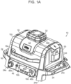
- the illustrated cooking system 10 includes a housing 12 having a generally rectangular configuration with top and bottom surfaces 12a, 12b, and four sides, including left, right, front, and back sides 12c, 12d, 12e, 12f.
- the particular shape of the housing 12 can vary and certain surfaces can be rounded or have other variations that alter the appearance of the housing 12.
- the sides 12c, 12d, 12e, 12f of the housing 12 diverge from the top surface 12a to the bottom surface 12b.
- Such a configuration can aid in providing stability, since the bottom portion of the housing 12 is larger than the top portion of the housing 12.
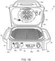
- the housing 12 further includes an interior hollow cooking chamber 14 defined within the housing 12, as shown in FIGS. 1B and 1D .
- the interior hollow cooking chamber 14 can be defined by a lower base portion 16 of the housing 12 and an upper lid portion 18 of the housing 12
- the lower base portion 16 can define a substantial portion of the hollow cooking chamber 14, with the upper lid portion 18 being movably coupled to the lower base portion 16 for selectively enclosing the hollow cooking chamber 14.
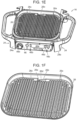
- the upper lid portion 18 is coupled to the lower base portion 16 via a rear hinge 20, such that the upper lid portion 18 is configured to move between a closed position wherein the hollow cooking chamber 14 is closed off from an external environment, such as depicted in FIGS. 1A and 1C , and an open position wherein the hollow cooking chamber 14 is open to an external environment, such as depicted in FIG. 1B .
- the upper lid portion 18 can include a handle 18a mounted on an exterior surface to facilitate opening and closing the upper lid portion 18. In the closed position, as a result of containing the hollow cooking chamber 14, the upper lid portion 18 can contact the lower base portion 16 at a perimeter region thereof where the sides of the lower base portion 16 and the upper lid portion 18 meet.
- One or both of the perimeter regions can include a gasket or perimeter seal, such as perimeter seal 18b shown on the upper lid portion 18 in FIG. 1B , that is configured to prevent airflow through the perimeter region.
- the perimeter seal 18b can be made from a heat-resistant material that can withstand temperatures reached by the cooking assembly 10 during cooking operations.
- the housing 12 can be formed from a heat-resistant material such that the housing 12 can support high cooking temperatures.
- the housing 12 can include additional elements.
- a support structure 24 having four feet 24a, 24b, 24c, 24d disposed at corners thereof can be formed on or coupled to the bottom surface 12b to aid in stabilization of the cooking system 10.
- a grill surface 26 can be formed on or disposed in the lower base portion 16 beneath an upper extent of the sidewalls and perimeter region thereof.
- the grill surface 26 can include ridged portions 26a thereon, however in other embodiments, the grill surface 26 can be planer without any ridges.
- the grill surface 26 can be made from food safe materials used in combination with high heat, such as cast iron, steel, enamel-coated metal, or other materials known in the art.
- a lower heating element 28, shown in FIG. 1D can be disposed beneath the grill surface 26 and it can configured to heat the grill surface 26 in order to facilitate conductive cooking operations therewith.
- the grill surface 26 can include a grease drain 26b positioned to allow for drainage of excess grease, fat, and other liquids and waste created during various cooking operations.
- the grease drain 26b can be positioned at various locations, but in the illustrated embodiment it is formed in a bottom surface of the grill surface 26 and is positioned at a mid-portion of a rear wall thereof, as shown.
- a channel 26c formed around an exterior of the grill surface 26 can aid in directing grease toward the grease drain 26a, and may be angled downward to provide a gravity-assisted flow toward the grease drain 26a.
- the grease drain 26b can be sized to minimize excess airflow therethrough, and in this way can facilitate substantial sealing of the hollow cooking chamber 14 when the upper lid portion 18 is in the closed position.
- the grease drain 26b includes a ramped surface 26d extending downward from the grill surface 26 to an opening 26e formed at the end thereof.
- a container or reservoir 22 shown in FIG. 1C , to aid in disposal and cleaning.
- the reservoir 22 can in the form of a pan or tray, or in other forms, and can be removably attached to the lower base portion 16 in order to further aid in disposal.
- the lower base portion 16 can also include a probe holder 40 and probe 42 that can be removably mounted onto the housing.
- the probe holder 40 with the probe 42 mounted therein can be sized to be received within a probe slot 16b, which is depicted in the form of a pair of arms that can retain the probe holder 40 therein.
- the probe 42 can be a temperature probe capable of interfacing with the cooking assembly 10 via a data port (not shown). While interfacing with the data port, the probe can be inserted into a food product to monitor a temperature thereof during a cooking process.
- the upper lid portion 18 can also include various features and elements.
- a fan 30 can be disposed on an upper interior surface of the upper lid portion 18, near a central region and within the hollow cooking chamber 14.
- the fan 30 can be configured to circulate air throughout the hollow cooking chamber 14 when in use.
- the fan 30 can circulate air in a variety of patterns, such as, for example, in a toroidal pattern, wherein air flows upward in the center region of the hollow cooking chamber 14 and then once it reaches the bottom of the cooking chamber 14, it can flow outward and downward in a second, opposite direction at the periphery of the hollow cooking chamber 14.
- the fan 30 can be electrically coupled to a motor (not shown) contained within a motor housing 32, and the motor housing 32 can centrally disposed on top of the upper lid portion 18.
- the motor housing 32 can include an additional fan 34 for cooling the motor, as well as vents 36 for providing air flow to the motor housing 32.
- Additional seal members (not shown) can be placed in the upper portion of the lid around electrical and mechanical fan components passing therethrough in order to contribute to further sealing of the hollow cooking chamber 14.
- the upper lid portion 18 can include an upper heating element 38 disposed on an interior thereof.
- the upper heating element 38 is disposed above the fan 30.
- the upper heating element 38 can be configured to operate in conjunction with the fan 30, such that the air circulated by the fan 30 in the hollow cooking chamber 14 is heated by the upper heating element 38, such that convection cooking operations can be performed by the cooking assembly 10.
- the upper lid portion can include a lid aperture 42 on an upper interior thereof that is configured to allow air to flow through the upper lid portion and into the hollow cooking chamber.
- the cooking system can include any number of fans and/or heating elements positioned at various locations.
- the upper lid portion 18 can include an exhaust port 18c located on a rear side thereof.
- the exhaust port 18c can be sized to allow for substantially the same rate of airflow to exit the hollow cooking chamber 14 as is entering the hollow cooking chamber 14 through a lid aperture 18d, which will be discussed in more detail below.
- FIGS. 1A-1D further depict an exemplary embodiment of a smoke assembly 50 coupled to the upper lid portion 18 of the housing 12 on an external surface thereof.
- the smoke assembly 50 while shown in the exemplary embodiment to be disposed external to the hollow cooking chamber 14, is in fluid communication with the hollow cooking chamber 14 via a lid aperture 18d such that smoke generated by the smoke assembly 50 can flow into the hollow cooking chamber 14 to be used during cooking operations to impart flavor onto food products.
- Various embodiments of the smoke assembly 50 will be discussed in greater detail below with respect to FIGS. 2A-9C .
- the lower base portion 16 can include a user interface 46 arranged thereon.
- the user interface 46 includes a display 46a configured to depict information about the cooking assembly 10, as well as various inputs 46b in the form of buttons and dials. These inputs 46b can set and adjust cooking operations of the cooking assembly 10, and can involve altering any of the features of the assembly 10, including the upper and lower heating elements 38, 28, the fan 30, and the smoke assembly 50.
- a controller (not shown) coupled to the user interface 46 is configured to run one or more software programs installed in the cooking system 10. These software programs may be directed to preset cooking operations, a plurality of operations executed in combination, and/or interruption programs which adjust in-progress operations with inputs received to modify the operation, such as from a user via the user interface 46, or from an external source.
- the cooking operations to be executed in combination can be executed simultaneously and/or in succession.
- the user interface 46, controller, cooking operations, and other functions will be discussed in greater detail below with respect to FIGS. 10-11 .
- the smoke assembly 50 is configured to generate smoke for use in a cooking operation.
- the smoke assembly 50 can be mounted to an exterior surface of the upper lid portion 18 and is configured to be in fluid communication with the hollow cooking chamber 14 via a lid aperture 18d.
- the smoke assembly 50 can include a smoke assembly housing 52 having a generally rectangular configuration with top and bottom surfaces 52a, 52b, and four sides - narrower left and right sides 52c, 52d, and wider front and rear sides 52e, 52f - that together form an interior cavity 54. As shown in FIGS.
- the front side 52e proximate the housing 12, is formed to fit a contour of the outer surface of the upper lid portion 18, and therefore may be shorter than the rear side 52f.
- the rear side 52f opposite the front side 52e, may include a first air intake 56a disposed at a lower region to allow air into the interior cavity 54.
- the top surface includes a lid 58 hinged to the smoke housing 52 that leads to the interior cavity 54.
- the lid 58 is biased to a closed position via a spring 58a with enough force to prevent accidental opening, or to prevent excess air from seeping into the interior cavity 54.
- the interior cavity 54 is sized to receive an insertable removable fuel box assembly 60 therein.
- the force exerted by spring 58a is large enough to prevent the fuel box assembly 60 from sliding out of the smoke assembly housing 52 when the upper lid portion 18 is in an open position.
- the fuel box assembly 60 can be configured to receive and retain fuel for use during a cooking operation, and the fuel box assembly 60 can also catch and hold ash generated by combustion of the fuel.
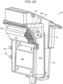
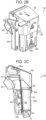
- the fuel box assembly 60 seen within the smoke assembly housing 52 in FIG. 2C and removed from the smoke assembly housing 52 in FIG. 2F , includes left and right sidewalls 60a, 60b, and front and rear sidewalls 60c, 60d, which are wider than the left and right sidewalls 60a, 60b similar to the smoke assembly housing 52.
- the fuel box assembly 60 also includes a top surface 60e and a bottom surface 60f which extend between the sidewalls 60a-d at respective top and bottom ends.
- the particular shape and arrangement of the fuel box assembly 60 can vary in dimension, and certain features can be rounded or generally altered from what is depicted.
- the front sidewall 60c, disposed proximate the housing 52, is shown covered by a mesh 64 with a plurality of small apertures 62a disposed thereon.
- the smoke assembly further includes a large aperture 62b.
- the particular amount and arrangement of apertures 62a, 62b can vary in number, arrangement, and/or dimension.
- the rear sidewall of the fuel box assembly 60 is substantially solid, except for at a lower region, which can contain a second air intake 56b that aligns with the first air intake 56a located on the rear sidewall of the smoke assembly housing 52.
- the first and second air intakes 56a, 56b define a portion of an airflow path through the cooking system 10.
- the fuel box assembly 60 is further configured to be placed within the smoke assembly housing 52 to substantially conform with the left, right, and rear sides.
- a region near the front side of the smoke assembly housing 52 proximate the upper lid portion can be larger than a region occupied by the fuel box assembly 60, and is thus not filled by the fuel box assembly 60 when the fuel box assembly 60 is inserted into the smoke assembly housing 52.
- this region can contain an igniter 66, such as a wire heating element, that is configured to heat fuel contained in the fuel box assembly 60 through the smaller apertures 62a of the mesh 64 on the front fuel box assembly sidewall 60e.
- the igniter 66 can take on various forms, such as, for example, a electrical tubular heating element or a sparking device. When smoke generation is required for a cooking operation, the igniter 66 can be powered on to ignite fuel contained in the fuel box assembly 60.
- the fuel box assembly 60 has an interior space. This interior space is divided into two regions, an upper region in the form of a pellet box 68 that is configured to receive and hold fuel for use during a smoke generation process, and a lower region in the form of an ash catcher 70 that is configured to receive and store ash created during a smoke generation process.
- the pellet box 68 and the ash catcher 70 are shown in the illustrated embodiment as being separated by a mesh divider 72.
- the mesh divider 72 includes apertures which are sized to be large enough to allow for ash to fall from the pellet box 68 to the ash catcher 70 during a smoke generation process, while also being small enough to prevent fuel from passing through the mesh divider 72.
- the ash catcher 70 is further configured to retain ash generated by the fuel box assembly 60, such that removal of the fuel box assembly 60 from the smoke assembly housing 52 will also remove ash from the smoke assembly housing 52 to facilitate disposal and prevent ash spillage.
- a person skilled in the art will appreciate that other techniques can be used to separate ash from the fuel.
- the smoke assembly 50 can include a temperature sensor 74 disposed proximate to the fuel box assembly 60.
- the temperature sensor 74 can take on any suitable form, and, for example, may be one of a thermocouple, a resistance temperature detector (RTD), a thermistor, and a semiconductor based integrated circuit. However, any form of sensor capable of measuring temperature can be used.
- the temperature sensor 74 is configured to measure a temperature of the interior of the fuel box assembly 60 during smoke processes and non-smoke processes.
- the smoke assembly interior 54 including the interior of both the smoke assembly housing 52 and the fuel box assembly 60, are in fluid communication with the hollow cooking chamber 14.
- the front sidewall of the smoke assembly 50 above the region containing the igniter 66, contains a large aperture 62b.
- the large aperture 62b defines part of the airflow pathway, joining the smoke assembly 50 interior with the hollow cooking chamber 14.
- Covering the large aperture 62b, as depicted in FIGS. 2A-2C is a baffle 80 disposed in the airflow path. When the smoke assembly 50 is coupled to the housing 10 at the lid aperture 18d, the baffle 80 passes through the lid aperture 18d and is thereby positioned within the hollow cooking chamber 14.
- the baffle 80 is a tunnel baffle 82.
- the tunnel baffle 82 can include a cover 82c spanning the large aperture 62b that is oriented horizontally to align with a direction of airflow in the hollow cooking chamber 14.
- the cover 82c can include openings at each end thereof such that, in relation to airflow through the hollow cooking chamber 14, one opening is an upstream opening 82a and the other opening is a downstream opening 82b.
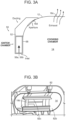
- FIGS. 3A-3E a simplified depiction of an airflow path through a cooking assembly is shown, along with graphs displaying a relationship between baffle dimension and airflow rates.
- the graph shown in FIG. 3C relates to length of baffle overhang versus airflow through the baffle
- the graph shown in FIG. 3E depicts a relationship between height of a baffle versus airflow through the baffle.
- FIG. 3A is simplified cross-sectional view of an airflow path, including an intake, such as intakes 56a, 56b, disposed at a bottom of a smoke assembly (e.g., smoke assembly 50).
- FIG. 3A further includes an aperture region, including large aperture 62b leading to the hollow cooking chamber 14 through which a baffle (e.g., tunnel baffle 82) would be disposed.
- An exhaust port 18c is also depicted, which allows for airflow to exit the hollow cooking chamber 14.
- the housing 12 and the smoke assembly 50 together define an airflow pathway configured to provide smoke generated by the smoke assembly 50 to the hollow cooking chamber 14 during a cooking operation.
- the flow of air through the smoke assembly 50 and into the hollow cooking chamber 14 can be enabled by a fan (e.g., fan 30) disposed in the upper lid portion 18.
- a fan e.g., fan 30
- air is introduced to the pathway through the first and second air intakes 56a, 56b contained in both the smoke assembly housing 52 and the fuel box assembly 60, respectively, at the rear side of the smoke assembly 50. After entering through the first and second intakes 56a, 56b, the airflow will then enter the interior of the fuel box assembly 60. If fuel in the pellet box 68 is being burned, the airflow will pick up generated smoke.
- the airflow will continue from the pellet box 68 into the hollow cooking chamber 14 via the baffle 80, drawn therein by the fan 30.
- the direction of airflow through the smoke assembly 50 - from the bottom to the top - aligns with the direction of the natural convection current of combusting fuel.
- the air intakes 56a, 56b are sized to be smaller than the exhaust 18c.
- the lid aperture 18d can be sized to be larger than both the air intakes 56a, 56b and the exhaust port 18c.
- the air intakes 56a, 56b each are approximately 2 cm 2 in size
- the exhaust port 18c is approximately 3 cm 2 in size
- the lid aperture 18d is approximately 20 cm 2 in size.
- FIGS. 3C and 3E depict graphics showing a relationship between baffle dimensions and airflow, for example FIG. 3C depicts adjustments of a length of baffle overhang as it affects a rate of airflow through a pellet box at two different fan speeds, 900 RPM and 2900 RPM, while FIG. 3E depicts adjustments of a baffle height as it affects a rate of airflow through a pellet box.
- FIG. 3C depicts adjustments of a length of baffle overhang as it affects a rate of airflow through a pellet box at two different fan speeds, 900 RPM and 2900 RPM
- FIG. 3E depicts adjustments of a baffle height as it affects a rate of airflow through a pellet box.
- baffle overhang has minimal impact on airflow rate.
- FIG. 3E as baffle height increases, so too does airflow through the baffle, approaching a near constant rate at approximately a 15 mm baffle height.
- FIGS. 4A and 4B depict an alternative embodiment of a tunnel baffle 82' having a hemispherical profile. Similar to the baffle 82, depicted in the exemplary embodiment of FIGS. 2A-2E , the tunnel baffle 82' covers a lid aperture 18d and includes an upstream opening 82a' and a downstream opening 82b to allow airflow through the tunnel baffle 80'.
- FIG. 4C depicts a simplified view of a tunnel baffle 80 and its various openings 82a, 82b, as well as a path of airflow with smoke entering the hollow cooking chamber 14 from a smoke assembly (e.g., smoke assembly 50).
- a smoke assembly e.g., smoke assembly 50
- the Venturi baffle 84 and fan 30 are configured to work in tandem, such that the baffle opening 84d is directed toward a leading direction of the fan 30 orientation in a downstream flow path.
- the baffle opening 84d can be directed such that airflow will be emitted from the baffle opening 84d in the clockwise orientation.
- the baffle opening 84d can be configured to emit airflow in the counter-clockwise orientation.
- FIG. 5C depicts a simplified view of the Venturi baffle 84 in relation to the airflow path.
- a smoke assembly e.g., smoke assembly 50
- a fan e.g., fan 30
- FIG. 6 shows a change in airflow to the hollow cooking chamber 14 versus baffle placement for both the tunnel baffle 82 and the Venturi baffle 84.
- the change in airflow is measured between two scenarios, a first scenario in which the hollow cooking chamber 14 includes a large food product, and a second scenario in which the hollow cooking chamber 14 does not include any food product.
- a corresponding smoke assembly e.g., smoke assembly 50
- the baffle type changes between a tunnel baffle and a Venturi baffle, or no baffle at all, airflow therethrough will also change.
- the tunnel baffle, Venturi baffle, and no baffle will also have altered airflow rates depending upon their position on the housing, depicted in the insert of FIG. 6 at numbers 1-7.
- FIGS. 7-9C illustrate additional embodiments of a smoke assembly similar to the smoke assembly 50 described above. Accordingly, like components are not described in detail. The embodiments featured are functional with the cooking system 10 depicted in FIGS. 1A-1H , as well as any other embodiments contemplated herein.
- FIGS. 7-8 depict two embodiments of a smoke assembly 50', 50" where the smoke assembly 50', 50" is arranged in an alternative orientation relative to the housing.
- the smoke assembly 50' is arranged in a substantially downward orientation at an approximately 45-degree angle relative to a side of the upper lid portion 18.
- the smoke assembly 50" is arranged in a substantially upward orientation at an approximately 45-degree angle relative to the side of the upper lid portion 18, and is offset from the orientation of the embodiment shown in FIG. 7 by approximately 90-degrees.
- the 7-8 include a smoke assembly housing 52', 52" and a fuel box assembly 60', 60" configured to be removably inserted into the smoke assembly housing 52', 52".
- the smoke assembly housing 52', 52" has a bottom surface 52a', 52a", a top surface 52b', 52b", and left 52c', 52c", right 52d', 52d", front 52e', 52e", and rear sides 52f', 52f".
- the fuel box assembly 60', 60" is divided into a pellet box 68', 68" and an ash catcher 70', 70" disposed in the pellet box 68', 68". As shown in FIGS.
- the ash catcher 70', 70" occupies a lower region of the fuel box assembly 60', 60".
- the smoke assembly 50', 50" further includes an igniter 66', 66" disposed within the smoke assembly housing 52', 52" and positioned proximate to a sidewall of the fuel box assembly 60', 60" containing a plurality of apertures 62a', 62a", and the igniter 66, 66" is configured to ignite fuel contained within the pellet box 68', 68".
- the smoke assembly 50', 50" defines part of an airflow path.
- the rear side 52f', 52f" of the smoke assembly housing 52', 52" and the rear side 68f', 68f" of the fuel box assembly 60', 60" each contain respective first 56a', 56a" and second 56b', 56b" air intakes that are aligned and configured to receive airflow therethrough and allow the airflow to enter the smoke assembly housing 52', 52" and the fuel box assembly 60', 60".
- the igniter 66', 66" is disposed above the smoke assembly 50', 50" and is configured to ignite fuel contained in the pellet box 68', 68" in a top-down manner.
- the fuel disposed closer to the igniter 66', 66" will combust first, continuing in a downward fashion to then combust fuel disposed further from the igniter 66', 66".
- the natural convection current created will cause smoke to travel from the combusting fuel in an upward direction. In the embodiment shown in FIG. 7 , this upward direction leads toward a baffle (e.g., Venturi baffle 84) to then enter the hollow cooking chamber 14.
- a baffle e.g., Venturi baffle 84
- this upward direction leads away from the Venturi baffle 84 toward the first 56a', 56a" and second intakes 56b', 56b".
- the Venturi effect will also operate to draw smoke from the combusting fuel through the Venturi baffle 84 and into the hollow chamber 14.
- this direction of Venturi draw is upward, and therefore the natural convection current and the Venturi flow are in substantial alignment.
- this direction of Venturi draw is downward, and therefore the natural convection current and the Venturi flow are misaligned.
- FIGS. 9A-9C depict another embodiment of a smoke assembly 50′′′.
- the smoke assembly 50′′′ is generally L-shaped and is curved so as to be configured to extend at least partially circumferentially around a fan 30 and upper heating element 38 within a hollow cooking chamber 14.
- the smoke assembly 50′′′ includes an arc-shaped base 50a′′′ having left 50c′′′, right 50d′′′, interior-facing 50e′′′, and exterior facing sides 50f", with the interior-facing direction being a radially-inward direction and the exterior-facing direction being a radially-outward direction.
- the left side 50c"' extends upwardly from the base 50a"' to a first height
- the right side 50d′′′ extends upwardly from the base 50a′′′ to a second, higher height
- the interior-facing 50e′′′ and exterior facing 50f" sides each have a left portion extending upwardly to the first height and a right portion extending upwardly to the second height, such that both of the interior-facing 50e′′′ and exterior facing 50f" sides have a substantially L-shaped facade.
- the smoke assembly 50′′′ also includes a stepped lid 58′′′ hinged to the left side 50c′′′, and the stepped lid 58′′′ is formed such that in a closed position, a left portion of the stepped lid 58′′′ is at the first height and a right portion of the lid 58′′′ is at the second height, and there is a vertically-oriented section of lid 58′′′ extending between the left and right portions. In this orientation, the lid 58′′′ can close the smoke assembly 50′′′, despite the height differential between the left and right portions.
- the smoke assembly 50′′′ further has an interior divided into first 52a′′′ and second 52b′′′ compartments, with a center divider 52c′′′ extending between the two compartments.
- the first compartment 52a"' is defined by the region having the first height
- the second compartment 52b′′′ is defined by the region having the second height.
- the smoke assembly 50′′′ is configured to be received within a slot 90 within the hollow cooking chamber 14, such that the smoke assembly 50′′′ is proximate the fan 30 and upper heating element 38.
- a slot 90 or cavity can be formed within the upper lid portion 18 to receive and retain the smoke assembly 50′′′ during a cooking operation.
- the upper heating element 38 is configured to ignite fuel contained within the smoke assembly 50"' through the apertures 62a"' located on the interior-facing sidewall, and smoke can be generated directly within the hollow cooking chamber 14 without the need for an air flow path to include components outside of the hollow cooking chamber 14.
- the cooking assembly 10 is operated by a user interface 46 located on an exterior of the front side of the housing 12.
- the user interface 46 is coupled to a controller that coordinates operation of the various components of the cooking assembly 10 based on instructions received at the user interface 46, as well as based on inputs measured by various sensors within the cooking system.
- These cooking operations include conductive, convective, and radiative heating methods, such as grilling, baking, air frying, dehydrating, and other known cooking methods. Further, these cooking operations include methods relying on smoke generated by the smoke assembly 50. Smoke methods can include low-and-slow, perfume smoke, and variable fan speed. Any of the listed operations can be used in combination with one another, both in succession or at the same time.
- the user interface 46 includes a smoke infusion input 46c, which can cause the smoke assembly 50 to generate smoke on-demand.
- the smoke infusion input 46c can be used with any other cooking operation as a means by which additional smoke flavor can be imparted onto a food product as desired. If smoke functionality is not already in use, actuation of the smoke infusion input 46c can cause the igniter 66 to ignite fuel stored in the pellet box 68. If smoke functionality is already in use, actuation of the smoke infusion input 46c can cause the fan 30 to draw more smoke into the hollow cooking chamber 14.
- actuation of the smoke infusion input 46c can result in various changes to the cooking assembly 10 based on detected stimuli during a cooking operation, which result in the generation of more smoke for imparting cooking flavor onto a food product. For example, if a detected temperature in the smoke assembly 50 is low, indicating a weak ember, actuation of the smoke infusion input 46c may cause the fan 30 to increase a fan speed, thereby pulling more air through the airflow path to grow the ember and generate additional smoke. In these embodiments, the generation of smoke is the outcome, however the system can determine how to go about generating more smoke based on detected stimuli.
- Figure 10 depicts a graphical representation of a relationship between burn temperature and type of smoke produced.
- smoke may contain larger particles which can import acrid, bitter flavors onto food products.
- burn temperatures between these two bounds i.e., between approximately 570 degrees Fahrenheit and below 750 degrees Fahrenheit, produce what is commonly known as "blue" smoke, which imparts pleasant smoke flavors onto food products. Therefore, in certain embodiments, it is desirable to maintain a burn temperature within this "blue" smoke range while smoke is generated. This maintenance can be accomplished through the control and adjustment of the listed factors, above.
- the embodiments described herein can be used with a variety of fuel types, such as wood pellets, wood chips, herbs, and other kinds known in the art. Certain fuel types will produce smoke at different rates, and consistency across fuel types can vary wildly. Moreover, the amount of fuel contained in the pellet box can greatly impact the volume of smoke generated over a smoke duration.
- the smoke assembly 50 can be refilled during a smoke generation process in order to generate more smoke. However, in other embodiments, less smoke may be desired in order to impart less smoke flavor onto a food product. In these embodiments, the smoke assembly 50 can be filled part way with fuel, or it can be filled with a fuel which generates less smoke, or which burns faster.
- the amount of airflow through the airflow path 50 can feed a combustion process, such that fuel is burned at a higher rate when a higher airflow is present.
- smoke generation is desired for a longer timeframe, then slowing the combustion process may be required.
- the amount of airflow being fed into the smoke assembly 50 can be determined by the operation speed of the fan 30. Because the fan 30 is drawing airflow through the airflow path, higher fan speeds will pull more oxygen into the smoke assembly and increase the combustion rate of fuel, while lower fan speeds will pull less oxygen and decrease the combustion rate.
- the cooking assembly 10 can operate in a low-and-slow cooking mode in which smoke is generated by the smoke assembly 50 and then circulated in the hollow cooking chamber 14 over the duration of the cooking operation.
- the smoke assembly 50 is filled to a maximum level with fuel prior to commencement of a cooking process.
- the low-and-slow mode is selected at the user interface 46, which then powers on an igniter 66 to ignite the fuel. Once the fuel is ignited, the fan 30 is operated at a low speed to prolong smoke generation in order to maximize the amount of smoke flavor imparted onto a food product.
- the cooking assembly 10 can operate in a perfume smoke mode in which smoke is generated by the smoke assembly 50 and then circulated in the hollow cooking chamber 14 just long enough to impart smoke flavor onto a food product.
- the smoke assembly 50 is filled only partially with fuel.
- only a first compartment of the smoke assembly will hold pellets. Operation in a perfume smoke mode generates a lower smoke volume and can be used in conjunction with other cooking modes to enhance the flavor of a food product without requiring extensive smoke generation.
- the cooking assembly can operate in a variable fan speed mode in which the fan 30 is operated at varying speeds during the duration of a cooking process in order to alter the quality and quantity of smoke generated by a smoke assembly.
- a variable fan speed mode can be used in combination with other smoke modes such as the low-and-slow mode or the perfume smoke mode discussed above.
- the igniter 66 ignites fuel stored in a smoke assembly 50.
- a temperature sensor 74 can monitor an internal temperature of the smoke assembly to gauge the size and temperature of the ember, and therefore the rate at which fuel is being consumed.
- the fan 30 can increase a fan speed to pull more air through the airflow path.
- the temperature of the ember is monitored by a temperature sensor 74, and a fan speed is adjusted to maintain an ember of sufficient size and temperature to produce ideal smoke conditions, based on user commands, sensed data, or a combination thereof.
- the temperature sensor 74 may detect that the internal temperature has fallen below a lower threshold, or that the temperature has changed too much in a given period of time.
- This lower threshold or change in temperature can be set to correspond to a weak ember or to an ember which has extinguished after ignition.
- the igniter 66 can be configured to attempt re-ignition of fuel in the smoke assembly to begin a new combustion process and/or to grow an existing ember. In embodiments where the igniter 66 creates a spark, the attempted re-ignition may involve sparking at regular or irregular intervals.
- the attempted re-ignition may involve powering on for a specific duration of time. These re-ignition attempts may continue for a specific duration or until the internal temperature rises to a certain level without the assistance of the igniter 66, thereby indicating that combustion of fuel has reached a satisfactory level for smoke generation.
- the system determines that re-ignition is unsuccessful, such as the internal temperature does not increase above the lower threshold, or the internal temperature does not increase at a certain rate, the system will cease re-ignition attempts. For example, this may occur if the fuel assembly no long has fuel, and therefore combustion is not possible with the smoke assembly 50.
- the system can display a message on the user interface 46 to provide a status of the attempted re-ignition in order to notify a user of the status. For example, if re-ignition is successful, a message indicating re-ignition can be displayed.
- FIG. 11 A graph of temperature versus time in the context of smoke assembly ignition and burn is depicted in FIG. 11 .
- this graph there is a sharp vertical spike in temperature which coincides with afterburn taking place in a cooking assembly.
- This temperature falls well within the heightened temperature zone, i.e., above 750 degrees Fahrenheit, depicted in FIG. 10 , and would therefore impart little to no flavor onto a food product.
- the fuel inside the smoke assembly 50 could be consumed at a high and undesirable rate.
- Approximating language may be applied to modify any quantitative representation that could permissibly vary without resulting in a change in the basic function to which it is related. Accordingly, a value modified by a term or terms, such as “about,” “approximately,” and “substantially,” are not to be limited to the precise value specified. In at least some instances, the approximating language may correspond to the precision of an instrument for measuring the value.
- range limitations may be combined and/or interchanged, such ranges are identified and include all the sub-ranges contained therein unless context or language indicates otherwise.
Landscapes
- Engineering & Computer Science (AREA)
- Food Science & Technology (AREA)
- Chemical & Material Sciences (AREA)
- Life Sciences & Earth Sciences (AREA)
- Combustion & Propulsion (AREA)
- Wood Science & Technology (AREA)
- Zoology (AREA)
- Polymers & Plastics (AREA)
- Mechanical Engineering (AREA)
- General Engineering & Computer Science (AREA)
- Baking, Grill, Roasting (AREA)
Applications Claiming Priority (4)
| Application Number | Priority Date | Filing Date | Title |
|---|---|---|---|
| US202263325129P | 2022-03-29 | 2022-03-29 | |
| US17/733,237 US12446730B2 (en) | 2022-03-29 | 2022-04-29 | Grill system with smoke assembly |
| US17/837,936 US12478213B2 (en) | 2022-03-29 | 2022-06-10 | Grill system with smoke assembly |
| EP22183967.3A EP4252599B1 (de) | 2022-03-29 | 2022-07-08 | Grillsystem mit rauchanordnung |
Related Parent Applications (1)
| Application Number | Title | Priority Date | Filing Date |
|---|---|---|---|
| EP22183967.3A Division EP4252599B1 (de) | 2022-03-29 | 2022-07-08 | Grillsystem mit rauchanordnung |
Publications (3)
| Publication Number | Publication Date |
|---|---|
| EP4430997A2 true EP4430997A2 (de) | 2024-09-18 |
| EP4430997A3 EP4430997A3 (de) | 2024-12-18 |
| EP4430997B1 EP4430997B1 (de) | 2026-03-18 |
Family
ID=82404442
Family Applications (2)
| Application Number | Title | Priority Date | Filing Date |
|---|---|---|---|
| EP24175992.7A Active EP4430997B1 (de) | 2022-03-29 | 2022-07-08 | Grillsystem mit rauchvorrichtung |
| EP22183967.3A Active EP4252599B1 (de) | 2022-03-29 | 2022-07-08 | Grillsystem mit rauchanordnung |
Family Applications After (1)
| Application Number | Title | Priority Date | Filing Date |
|---|---|---|---|
| EP22183967.3A Active EP4252599B1 (de) | 2022-03-29 | 2022-07-08 | Grillsystem mit rauchanordnung |
Country Status (6)
| Country | Link |
|---|---|
| US (2) | US12478213B2 (de) |
| EP (2) | EP4430997B1 (de) |
| CN (1) | CN218588838U (de) |
| AU (1) | AU2022450402A1 (de) |
| DE (1) | DE202022103811U1 (de) |
| WO (1) | WO2023191891A1 (de) |
Families Citing this family (2)
| Publication number | Priority date | Publication date | Assignee | Title |
|---|---|---|---|---|
| CN116919192A (zh) * | 2022-03-29 | 2023-10-24 | 尚科宁家运营有限公司 | 带烟熏组件的烤架系统 |
| US11849884B1 (en) * | 2023-06-01 | 2023-12-26 | Sharkninja Operating Llc | Methods and systems for ignition of a smoke unit fuel source |
Family Cites Families (208)
| Publication number | Priority date | Publication date | Assignee | Title |
|---|---|---|---|---|
| US3665840A (en) * | 1970-09-09 | 1972-05-30 | Johnny O Horany | Broiler including cooking plate |
| US4700618A (en) * | 1985-08-06 | 1987-10-20 | David M. Cox, Jr. | Meat smoker |
| US4865219A (en) | 1987-04-20 | 1989-09-12 | Logan - Barlow | Serving platter for pizza pan |
| US20090087534A1 (en) | 2002-08-14 | 2009-04-02 | Mclemore John D | Cooking apparatus |
| US6941857B2 (en) | 2002-08-14 | 2005-09-13 | Mclemore John D. | Cooking apparatus |
| US7412922B2 (en) | 2002-08-14 | 2008-08-19 | Mclemore John D | Cooking apparatus |
| FR2844695B1 (fr) | 2002-09-20 | 2006-03-31 | Seb Sa | Appareil electromenager a panneaux articules |
| FR2844956B1 (fr) | 2002-09-24 | 2004-11-19 | Seb Sa | Thermostat de four |
| FR2853721B1 (fr) | 2003-04-11 | 2006-05-26 | Seb Sa | Appareil de cuisson double face a dispositif d'evacuation de vapeur |
| US6868777B1 (en) | 2003-07-09 | 2005-03-22 | Mike Higgins | Cooker and smoker apparatus and method of smoke generation, recirculation, and exhaust |
| US7703389B2 (en) | 2003-08-14 | 2010-04-27 | Mclemore John D | Cooking apparatus with cooking characteristic monitoring system |
| US7426885B2 (en) | 2004-12-23 | 2008-09-23 | Mclemore Don | Cooking device |
| KR20050026609A (ko) | 2003-09-09 | 2005-03-15 | 삼성전자주식회사 | 모듈식 그릴 조리기 및 이 그릴 조리기를 구비한 복합조리장치 |
| KR20050026610A (ko) | 2003-09-09 | 2005-03-15 | 삼성전자주식회사 | 그릴 조리기 및 이 그릴 조리기를 구비한 복합 조리장치 |
| US6810792B1 (en) | 2003-12-17 | 2004-11-02 | David B. Knight & Associates, Inc. | Barbecue oven having improved heat circulation |
| US7451691B2 (en) * | 2004-03-16 | 2008-11-18 | Robertson Michael L | No waste cooking oven with multiple cooking functions |
| CA2569972C (en) | 2004-06-08 | 2012-07-24 | Seb S.A. | Air flow cooking device |
| US7757604B2 (en) | 2005-11-15 | 2010-07-20 | Weber-Stephen Products Co. | Smoke enhancer |
| FR2893831A1 (fr) | 2005-11-30 | 2007-06-01 | Seb Sa | Dispositif de cuisson |
| FR2893832B1 (fr) | 2005-11-30 | 2012-02-10 | Seb Sa | Appareil de cuisson |
| US7832330B1 (en) | 2005-12-06 | 2010-11-16 | Thompson Donald E | Cooker to smoker adapter |
| FR2895222B1 (fr) | 2005-12-22 | 2010-01-01 | Seb Sa | Appareil de cuisson comprenant un sous-ensemble d'alimentation et de commande simplifie |
| JP2007289649A (ja) | 2006-04-20 | 2007-11-08 | Kyu Suk Kang | ロースターの空気循環システムおよびロースター |
| US20120012096A1 (en) | 2006-10-06 | 2012-01-19 | Cusack William E | Venturi Vent Assembly For Outdoor Cookers |
| CN201150469Y (zh) | 2008-01-29 | 2008-11-19 | 厦门灿坤实业股份有限公司 | 一种带可拆卸烟熏结构的煎烤器 |
| AU2014208185B2 (en) | 2008-04-17 | 2015-08-20 | Breville Pty Limited | Countertop Oven and Accessories |
| AU2009238211B2 (en) | 2008-04-17 | 2014-12-04 | Breville Pty Limited | Countertop oven and accessories |
| US8304696B2 (en) | 2008-07-01 | 2012-11-06 | Knight David B | Air circulator for an oven |
| AU2009202799A1 (en) | 2008-07-11 | 2010-01-28 | Breville Pty Limited | Toaster Oven |
| US8109263B2 (en) | 2008-12-09 | 2012-02-07 | Whirlpool Corporation | User activated grease tray drain |
| US8931400B1 (en) | 2009-05-28 | 2015-01-13 | iDevices. LLC | Remote cooking systems and methods |
| CN101953645B (zh) | 2009-07-16 | 2016-01-13 | 布瑞威利私人有限公司 | 烤箱 |
| FR2955761B1 (fr) | 2010-02-01 | 2012-04-27 | Seb Sa | Appareil de cuisson electrique a plaque de cuisson amovible |
| EP2605690B1 (de) | 2010-08-16 | 2014-11-05 | Carrier Commercial Refrigeration, Inc. | Grill mit grillwerkzeughalter |
| DE102010046556A1 (de) | 2010-09-27 | 2011-06-16 | SEVERIN ELEKTROGERÄTE GmbH | Elektrisches Grillgerät |
| US9631820B2 (en) | 2010-10-05 | 2017-04-25 | Breville Pty Limited | Countertop oven accessories |
| CN202445881U (zh) | 2011-02-01 | 2012-09-26 | 创科电动工具科技有限公司 | 对流式烤架 |
| EP2739191B1 (de) | 2011-08-05 | 2018-09-26 | Breville Pty Limited | Verfahren und vorrichtung zur intuitiven steuerung von kochprozessen |
| KR101312988B1 (ko) | 2011-09-21 | 2013-10-01 | (주)토탈에프앤비 | 훈제조리기 |
| FR2985649B1 (fr) | 2012-01-16 | 2016-03-11 | Seb Sa | Procede de cuisson d'aliments et appareil mettant en oeuvre ce procede |
| FR2991862B1 (fr) | 2012-06-15 | 2015-04-24 | Seb Sa | Appareil de cuisson et son procede de mise en oeuvre |
| AU2013313006B2 (en) | 2012-09-06 | 2017-05-18 | Breville Pty Limited | Waffle maker |
| FR2997281B1 (fr) | 2012-10-31 | 2014-12-19 | Seb Sa | Appareil de cuisson electrique a flux d'air |
| AU2013337610B2 (en) | 2012-11-01 | 2017-03-02 | Breville Pty Limited | Microwave oven |
| US9182129B2 (en) | 2013-02-20 | 2015-11-10 | Gri Capital, Llc | System, device, and method for baking a food product |
| US9138100B2 (en) | 2013-03-14 | 2015-09-22 | Scott Hofmann | Igniter for solid cooking fuels |
| CN105263378B (zh) | 2013-03-15 | 2018-05-25 | 凯文·比呢特 | 烧烤熏制器设备 |
| US9486000B2 (en) | 2013-03-15 | 2016-11-08 | Mark Kaderli | Grilltop smoker box |
| US20140360387A1 (en) * | 2013-06-11 | 2014-12-11 | Jon Eric Bogdon | Cool temperature smoker |
| US9510604B2 (en) | 2013-06-17 | 2016-12-06 | W.C. Bradley Co. | Outdoor cooker and smoker, and fuel combustor therefor |
| CN203328547U (zh) | 2013-07-02 | 2013-12-11 | 上海一揽实业有限公司 | 一种用于烤炉的带有烟熏功能的引火板 |
| US9375021B2 (en) | 2013-07-29 | 2016-06-28 | Alto-Shaam, Inc. | Combination oven with reduced smoke flavor transfer |
| US9504354B1 (en) | 2013-08-23 | 2016-11-29 | Salvador Ficarra | Combination barbecue grill and smoker apparatus |
| US9441838B2 (en) | 2013-11-18 | 2016-09-13 | Edward Baker | Pellet bin insert and storage system for smoker grills |
| US9883770B2 (en) | 2014-03-11 | 2018-02-06 | Bonnie Lee Buzick | Vertical grill with external drip tray module |
| CN203852233U (zh) | 2014-03-28 | 2014-10-01 | 上海星级酒店设备工程有限公司 | 一种具有烧烤炉和电扒炉的圆形组合式炉具 |
| FR3019763B1 (fr) | 2014-04-10 | 2019-11-29 | Gb Developpement | Dispositif distributeur de fluide et valve munie d'un moyen de rappel |
| AU2015255207B2 (en) | 2014-05-14 | 2016-09-22 | Southern Pride Distributing, Llc | Smoker oven with improved air flow |
| US20180132660A1 (en) | 2014-06-11 | 2018-05-17 | Robert V. Suchevits | Grill and smoker convertible configuration device and method |
| US10067004B1 (en) | 2014-11-04 | 2018-09-04 | Weber-Stephen Products Llc | Wireless temperature monitoring systems and methods of food |
| WO2016093481A1 (ko) | 2014-12-10 | 2016-06-16 | 주식회사 효신테크 | 내장형 훈연 기능을 포함한 콤비 오븐 |
| FR3030211B1 (fr) | 2014-12-23 | 2017-01-13 | Seb Sa | Accessoire de diffusion de fumee pour barbecue electrique |
| EP3273786B8 (de) | 2015-03-25 | 2020-03-04 | W.C. Bradley Co. | Vertikaler elektrischer ofen und smoker mit rauchkammer |
| CN107430411B (zh) | 2015-03-30 | 2020-08-28 | 布瑞威利私人有限公司 | 加热元件的控制 |
| US9603372B2 (en) | 2015-06-01 | 2017-03-28 | Emil Paul Bader | Wood chip smoker for outdoor grills |
| AU2016276039A1 (en) | 2015-06-08 | 2017-12-21 | Masterbuilt Manufacturing, Inc. | Gas-fired smoker with digital temperature control |
| CN108093620A (zh) | 2015-06-08 | 2018-05-29 | 万事得制造有限责任公司 | 具有机械温度控制的独立式燃气烟熏器 |
| CN206053603U (zh) | 2015-06-22 | 2017-03-29 | 布瑞威利私人有限公司 | 软关闭门组件 |
| EP3342291B1 (de) | 2015-08-27 | 2019-04-03 | Panasonic Intellectual Property Management Co., Ltd. | Rauchvorrichtung |
| WO2017044619A1 (en) | 2015-09-09 | 2017-03-16 | Traeger Pellet Grills, Llc | Internal chimney system for grills and smokers |
| US10455979B2 (en) | 2015-09-09 | 2019-10-29 | Traeger Pellet Grills, Llc | Smoke trap apparatus and system |
| CN105167640B (zh) | 2015-09-15 | 2017-08-25 | 刘华 | 熏烤箱 |
| US10757244B2 (en) | 2015-10-23 | 2020-08-25 | Traeger Pellet Grills, Llc | Cloud system for controlling outdoor grill with mobile application |
| US10785363B2 (en) | 2015-10-23 | 2020-09-22 | Traeger Pellet Grills, Llc | Cloud system for controlling outdoor grill with mobile application |
| US10708409B2 (en) | 2015-10-23 | 2020-07-07 | Traeger Pellet Grills, Llc | Mobile application for controlling outdoor grill |
| US10735575B2 (en) | 2015-10-23 | 2020-08-04 | Traeger Pellet Grills, Llc | Mobile application for controlling outdoor grill |
| US10701199B2 (en) | 2015-10-23 | 2020-06-30 | Traeger Pellet Grills, Llc | Cloud system for controlling outdoor grill with mobile application |
| US10218833B2 (en) | 2015-10-23 | 2019-02-26 | Traeger Pellet Grills, Llc | Mobile application for controlling outdoor grill |
| US10455022B2 (en) | 2015-10-23 | 2019-10-22 | Traeger Pellet Grills, Llc | Cloud system for controlling outdoor grill with mobile application |
| US11825010B2 (en) | 2015-10-23 | 2023-11-21 | Traeger Pellet Grills, Llc | Mobile application for controlling outdoor grill |
| AU2016329040B2 (en) | 2015-10-23 | 2021-07-29 | Traeger Pellet Grills, Llc | Cloud system for controlling outdoor grill with mobile application |
| CN119806252A (zh) | 2015-10-23 | 2025-04-11 | 特雷格佩列特烤架有限公司 | 烟生成烹饪系统和方法 |
| US10491738B2 (en) | 2015-10-23 | 2019-11-26 | Traeger Pellet Grills, Llc | Cloud system for controlling outdoor grill with mobile application |
| US10791208B2 (en) | 2015-10-23 | 2020-09-29 | Traeger Pellet Grills, Llc | Mobile application for controlling outdoor grill |
| CA2948368A1 (en) | 2015-11-15 | 2017-05-15 | Arun Hingorani | Portable wood smoker |
| US10517427B2 (en) | 2015-11-23 | 2019-12-31 | Bbqguys Manufacturing, Llc | Cooking apparatus |
| US10327584B2 (en) | 2016-01-29 | 2019-06-25 | Evo, Inc. | Indoor/outdoor cooking system |
| CN205391021U (zh) | 2016-02-05 | 2016-07-27 | 林志昂 | 集油式烧烤架 |
| US10045546B2 (en) | 2016-02-18 | 2018-08-14 | Masterbuilt Manufacturing, Llc | Electric food smoker |
| FR3047884B1 (fr) | 2016-02-22 | 2018-02-16 | Seb S.A. | Appareil de cuisson a flux d'air |
| CN105662170B (zh) | 2016-02-22 | 2018-02-16 | 浙江福得尔电器有限公司 | 一种熏烟盒及具有熏烟盒的电熏烟炉 |
| US10021888B2 (en) | 2016-03-17 | 2018-07-17 | Curtis Glenn McLamb | Vertical smoker and cooker for food |
| US10641495B2 (en) | 2016-04-26 | 2020-05-05 | Justin Hamm | Smoker attachment for gas grill |
| US10660473B2 (en) | 2016-05-04 | 2020-05-26 | North Atlantic Imports, Llc | System, device and method for controlling convective heating of a griddle |
| US10327589B1 (en) | 2016-05-04 | 2019-06-25 | North Atlantic Imports, Llc | Outdoor cooking station with griddle, system and method thereof |
| US10327588B2 (en) | 2016-05-04 | 2019-06-25 | North Atlantic Imports, Llc | Griddle device, system, and method |
| US10588461B2 (en) | 2017-01-31 | 2020-03-17 | North Atlantic Imports, Llc | Portable outdoor cooking device, system, and accessory thereof |
| EP3249303B1 (de) * | 2016-05-24 | 2019-09-04 | Electrolux Appliances Aktiebolag | System zum räuchern und zur aromatisierung von lebensmitteln |
| WO2017214195A1 (en) | 2016-06-06 | 2017-12-14 | Brain Brew Ventures 3.0 Llc | Method for creating smoked foods and beverages |
| CA3066219A1 (en) * | 2016-06-17 | 2017-12-21 | KBQ Technologies, LLC | Apparatus for temperature control of barbecue oven |
| US10551893B2 (en) | 2016-07-01 | 2020-02-04 | Weber-Stephen Products Llc | Digital power supply with wireless monitoring and control |
| US10537199B2 (en) | 2016-07-01 | 2020-01-21 | Weber-Stephen Products Llc | Digital power supply |
| US10524312B2 (en) | 2016-07-01 | 2019-12-31 | Weber-Stephen Products Llc | Electric grill with current protection circuitry |
| US11454677B2 (en) | 2016-07-01 | 2022-09-27 | Weber-Stephen Products Llc | Wireless control and status monitoring for electric grill with current protection circuitry |
| WO2018022772A1 (en) | 2016-07-26 | 2018-02-01 | W.C. Bradley Co. | Smoker with variable configuration |
| CN206062956U (zh) | 2016-07-29 | 2017-04-05 | 苏州泽海电子塑胶有限公司 | 烟熏颗粒烤炉 |
| CA3037207A1 (en) | 2016-09-16 | 2019-03-14 | Masterbuilt Manufacturing, Llc | Smoker with top heat source |
| CN206295269U (zh) | 2016-09-21 | 2017-07-04 | 广东康宝五金有限公司 | 一种全自动烟熏烤炉 |
| US10888193B2 (en) | 2017-01-31 | 2021-01-12 | North Atlantic Imports, Llc | Portable outdoor cooking device, system, and accessory thereof |
| US11751723B2 (en) | 2017-01-31 | 2023-09-12 | North Atlantic Imports, Llc | Portable outdoor cooking device, system, and accessory thereof |
| CN206979387U (zh) | 2017-03-06 | 2018-02-09 | 安平县九坤丝网制造有限公司 | 一种管状烧烤烟熏筒 |
| CN207236672U (zh) | 2017-03-13 | 2018-04-17 | 关中股份有限公司 | 烧烤炉的均温保护、导油构造 |
| AU2018246127A1 (en) | 2017-03-31 | 2019-10-17 | Masterbuilt Manufacturing, Llc | Smoker with smoke management system |
| AU2018251790A1 (en) | 2017-04-12 | 2019-10-17 | Masterbuilt Manufacturing, Llc | Smoker or grill ash management system |
| AU2018202492B2 (en) | 2017-05-05 | 2019-11-07 | Weber-Stephen Products Llc | Wireless control and status monitoring for electric grill with current protection circuitry |
| CA3000542C (en) | 2017-05-05 | 2021-11-02 | Weber-Stephen Products Llc | Digital power supply with wireless monitoring and control |
| US10772467B2 (en) | 2017-05-08 | 2020-09-15 | North Atlantic Imports, Llc | Cooking station and system with removable insert having multiple cooking modes |
| US20180325314A1 (en) | 2017-05-09 | 2018-11-15 | Phase 2, Llc | Grills having flavorizing material containers |
| CN108433563A (zh) | 2018-03-13 | 2018-08-24 | 冯复都 | 陶瓷烤炉及其炉体上插入盒的安装方法 |
| WO2018208919A1 (en) | 2017-05-09 | 2018-11-15 | Phase 2, Llc | Pellet grills and grills having flavorizing material containers |
| US10912413B2 (en) | 2017-09-05 | 2021-02-09 | Phase 2, Llc | Pellet grill |
| EP3621500A1 (de) | 2017-05-09 | 2020-03-18 | Phase 2, LLC | Pelletgrills und grills mit aromatisierenden materialbehältern |
| CN106963248B (zh) | 2017-05-14 | 2019-01-22 | 河南工业大学 | 家用自动熏烤肉炉 |
| CN107347967A (zh) | 2017-06-16 | 2017-11-17 | 湖南嘉圣农业科技发展有限公司 | 一种发烟机 |
| EP3644810A4 (de) | 2017-06-26 | 2021-03-10 | Logan Outdoor Products, LLC | Pelletgrillsystem mit direkter und indirekter wärme |
| CN115813223A (zh) | 2017-06-30 | 2023-03-21 | 布瑞威利私人有限公司 | 比萨饼烹饪用具 |
| EP3648608B1 (de) | 2017-07-06 | 2023-08-02 | Breville Pty Limited | Einziehbare tür für einen ofen |
| EP3450855B1 (de) | 2017-08-31 | 2022-06-22 | SEB Asia Limited | Miniofen mit einem abdeckelement für die öffnung des backraums des miniofens |
| FR3079600B1 (fr) | 2018-03-28 | 2020-09-18 | Seb Asia Ltd | Element couvrant pour une ouverture d'une cavite de cuisson d'un mini-four |
| IT201700118716A1 (it) | 2017-10-19 | 2019-04-19 | Angelo Po Grandi Cucine Spa | Apparato di affumicatura |
| US10995964B2 (en) | 2017-10-27 | 2021-05-04 | North Atlantic Imports, Llc | Wind guard system, device and method thereof |
| CN208524651U (zh) | 2017-10-30 | 2019-02-22 | 广东百胜图科技有限公司 | 一种具有烟熏功能的煎烤器 |
| US11045047B2 (en) * | 2017-11-10 | 2021-06-29 | Ron's Enterprises, Inc. | Variable capacity oven |
| US10624358B2 (en) | 2017-12-05 | 2020-04-21 | Lem Products Holding Llc | Electric smoker |
| CN108185836A (zh) | 2018-02-11 | 2018-06-22 | 广东依信嘉电气实业有限公司 | 一种独立控制式燃气烟熏烤炉 |
| US11162684B2 (en) | 2018-02-13 | 2021-11-02 | Traeger Pellet Grills, Llc | Pellet hopper liner |
| CN208510814U (zh) | 2018-02-24 | 2019-02-19 | 广东依信嘉电气实业有限公司 | 一种改进烟熏发生器的燃气式烟熏烤炉 |
| DE102019106552A1 (de) | 2018-03-19 | 2019-09-19 | Traeger Pellet Grills, Llc | Grill mit komponentenrückmeldung und fernüberwachung |
| US11678767B2 (en) | 2018-03-19 | 2023-06-20 | Traeger Pellet Grills Llc | Grill with component feedback and remote monitoring |
| FR3079120B1 (fr) | 2018-03-21 | 2021-03-05 | Seb Sa | Appareil de cuisson du type friteuse a air chaud avec une capacite de cuisson evolutive |
| US11181276B2 (en) | 2018-03-26 | 2021-11-23 | Traeger Pellet Grills Llc | Self-cleaning grill |
| DE102019107597A1 (de) | 2018-03-26 | 2019-09-26 | Traeger Pellet Grills, Llc | Zyklonische luftzirkulation für selbstreinigende grills |
| US10986960B2 (en) | 2018-03-26 | 2021-04-27 | Traeger Pellet Grills, Llc | Grill with battery power system and measurement |
| US11259667B2 (en) | 2018-03-26 | 2022-03-01 | Traeger Pellet Grills, Llc | Grill with cold smoke grilling modes |
| DE102019106990A1 (de) | 2018-03-26 | 2019-09-26 | Traeger Pellet Grills, Llc | Selbstreinigender Grill |
| US11350791B2 (en) | 2018-03-26 | 2022-06-07 | Traeger Pellet Grills, Llc | Self-cleaning grilling devices |
| CA3037934A1 (en) | 2018-03-26 | 2019-09-26 | Traeger Pellet Grills Llc | Grill with cold smoke grilling modes |
| CN209377377U (zh) | 2018-04-13 | 2019-09-13 | 漳州灿坤实业有限公司 | 烟熏煎烤器 |
| US20190320669A1 (en) | 2018-04-20 | 2019-10-24 | Masterbuilt Manufacturing, Llc | Smoker with smoke on demand system |
| US11006646B2 (en) | 2018-05-03 | 2021-05-18 | Haier Us Appliance Solutions, Inc. | System and method for regulating the flow of smoke in an indoor smoker |
| CA3098877A1 (en) | 2018-05-14 | 2019-11-21 | Traeger Pellet Grills Llc | Pellet hopper liner |
| US11116360B2 (en) | 2018-05-31 | 2021-09-14 | North Atlantic Imports, Llc | Outdoor cooking station with multiple independent cooking modes and method thereof |
| EP3801152A4 (de) | 2018-06-06 | 2022-03-16 | Lifetime Products, Inc. | Kochvorrichtung mit wärmequellen in einer gestapelten anordnung |
| US10292531B1 (en) | 2018-06-06 | 2019-05-21 | Innovative Product Solutions, LLC | Cooking device having heat sources in a stacked arrangement |
| US10806301B2 (en) | 2018-06-06 | 2020-10-20 | Lifetime Products, Inc. | Cooking device having a lower door |
| US20200053842A1 (en) * | 2018-08-10 | 2020-02-13 | Haier Us Appliance Solutions, Inc. | Convection cooking appliance and removable utensil for air frying |
| US20200054032A1 (en) | 2018-08-14 | 2020-02-20 | Haier Us Appliance Solutions, Inc. | Multi-chamber smoke tray for an indoor smoker |
| IL281701B2 (en) | 2018-09-20 | 2024-07-01 | Masterbuilt Mfg Llc | Gravity Fed Smoker |
| CA3115989A1 (en) | 2018-10-12 | 2020-04-16 | W.C. Bradley Co. | Pellet smoker |
| EP3870008A4 (de) | 2018-10-23 | 2022-08-17 | Breville Pty Limited | Kochgerät |
| AU2019371756A1 (en) | 2018-10-29 | 2021-02-25 | Keowee Smokers & Grill Accessories Llc | Smoker device |
| CN209315621U (zh) | 2018-11-08 | 2019-08-30 | 羊宏伟 | 一种陶瓷颗粒炉 |
| AU2019379860A1 (en) | 2018-11-16 | 2021-06-03 | Breville USA, Inc. | Estimating a characteristic of a food item |
| CN209300859U (zh) | 2018-11-22 | 2019-08-27 | 上海麦源实业有限公司 | 一种不锈钢圆形烟熏盒 |
| CN209826361U (zh) | 2018-12-18 | 2019-12-24 | 广东力升电器有限公司 | 一种带有烟熏功能的无烟烤箱 |
| US11443051B2 (en) | 2018-12-20 | 2022-09-13 | Advanced Micro Devices, Inc. | Secure computer vision processing |
| CN209482113U (zh) | 2018-12-28 | 2019-10-11 | 长安大学 | 一种可快速加固的简支工字型组合梁 |
| CN113766861A (zh) | 2019-01-04 | 2021-12-07 | W.C.布拉德利公司 | 电池启用的颗粒烤架 |
| CA3066299C (en) | 2019-01-05 | 2022-04-26 | Traeger Pellet Grills, Llc | Pellet grills having pellet level detection systems and related methods |
| US11109600B2 (en) | 2019-01-14 | 2021-09-07 | Jordan Jackson | System and method for a pellet-fired smoker |
| US11248798B2 (en) | 2019-01-25 | 2022-02-15 | Weber-Stephen Products Llc | Pellet grills |
| CN212678957U (zh) | 2019-02-08 | 2021-03-12 | 沙克忍者运营有限责任公司 | 烹饪系统 |
| US20190254476A1 (en) * | 2019-02-25 | 2019-08-22 | Sharkninja Operating Llc | Cooking device and components thereof |
| CN114041028A (zh) | 2019-05-14 | 2022-02-11 | 特雷格佩列特烤架有限公司 | 颗粒料斗衬件 |
| CN211372488U (zh) | 2019-05-25 | 2020-08-28 | 阮前程 | 生物颗粒燃料燃烧气化一体炉 |
| FR3097732B1 (fr) | 2019-06-27 | 2022-12-16 | Seb Sa | Appareil de cuisson pour cuire des aliments avec ou sans pression. |
| FR3097733B1 (fr) | 2019-06-27 | 2021-07-23 | Seb Sa | Appareil de cuisson électrique pourvu d’un dispositif de chauffage démontable. |
| US12274394B2 (en) | 2019-07-12 | 2025-04-15 | North Atlantic Imports, Llc | Heat channeling system for outdoor cooking station and method thereof |
| CN114173566A (zh) | 2019-07-25 | 2022-03-11 | 弗兰克·布伦克霍斯特有限公司 | 冷烟熏烟熏器 |
| AU2020319805B2 (en) | 2019-07-29 | 2025-09-18 | Fisher & Paykel Appliances Limited | Oven smoker |
| AU2020347101A1 (en) | 2019-09-12 | 2022-04-07 | Breville Pty Limited | An oven |
| CN211212757U (zh) | 2019-10-31 | 2020-08-11 | 佛山市南海富达电业有限公司 | 一种立体式烟熏烘烤一体电热炉 |
| US11497349B2 (en) | 2019-12-10 | 2022-11-15 | Dansons Us, Llc | Indirect air flow system |
| CN211795985U (zh) | 2019-12-16 | 2020-10-30 | 上海纯米电子科技有限公司 | 烟熏盒及烤箱 |
| WO2021138455A1 (en) | 2019-12-31 | 2021-07-08 | Traeger Pellet Grills, Llc | Grill device, components of grill device, and related methods |
| MX2022008287A (es) | 2020-01-03 | 2022-08-08 | Breville R & D Pty Ltd | Aparato de cocina, metodo y sistema para cocinar al vacio. |
| US11963634B2 (en) | 2020-01-27 | 2024-04-23 | North Atlantic Imports, Llc | Adjustable warming rack and method thereof |
| US11877693B2 (en) | 2020-02-11 | 2024-01-23 | North Atlantic Imports, Llc | Griddle cooking station and method thereof |
| EP3865030B1 (de) | 2020-02-14 | 2024-08-28 | Application des Gaz | Grill und block für grill |
| EP4110063A4 (de) | 2020-02-28 | 2024-02-28 | W.C. Bradley Co. | Multimodaler kocher mit erweiterten steuerungen |
| US11624505B2 (en) | 2020-03-17 | 2023-04-11 | Weber-Stephen Products Llc | Ignition-based protocols for pellet grills |
| US12004546B2 (en) | 2020-03-27 | 2024-06-11 | Traeger Pellet Grills, LLC. | Method of cooking multiple different food items on a grill device and related systems methods |
| US12150590B2 (en) | 2020-04-09 | 2024-11-26 | North Atlantic Imports, Llc | Griddle cooking station with hood and method thereof |
| US20210352923A1 (en) | 2020-05-13 | 2021-11-18 | Dansons Us, Llc | Smoke generator, ultrasonic sound sensor and lid sensor |
| US20210369052A1 (en) | 2020-06-02 | 2021-12-02 | North Atlantic Imports, Llc | Outdoor cooking station for smoking food and method thereof |
| US11985985B2 (en) | 2020-07-27 | 2024-05-21 | North Atlantic Imports, Llc | Outdoor cooking station for smoking food and method thereof |
| EP4188168A4 (de) | 2020-07-31 | 2024-10-23 | W.C. Bradley Co. | Elektrischer grill und rauchvorrichtung |
| US20220061589A1 (en) | 2020-08-27 | 2022-03-03 | Sean Kristopher Dotson | Attachment for pellet grill hopper and methods of use thereof |
| CA3129781A1 (en) | 2020-09-04 | 2022-03-04 | Walmart Apollo, Llc | Outdoor pellet grill |
| CN116234446A (zh) | 2020-09-09 | 2023-06-06 | 布瑞威利私人有限公司 | 烤箱 |
| AU2021342516A1 (en) | 2020-09-18 | 2023-04-27 | Premier Specialty Brands, Llc | Portable charcoal grill and smoker |
| US11528918B2 (en) | 2020-11-03 | 2022-12-20 | Dansons Us, Llc | Smoke tube combustion chamber |
| US11125438B1 (en) * | 2020-11-20 | 2021-09-21 | Spider Grills, Llc | System and method for bimodal air control in a kettle-style grill |
| US11678768B2 (en) | 2020-11-24 | 2023-06-20 | Dansons Us, Llc | Air circulation device |
| FR3117325B1 (fr) | 2020-12-15 | 2023-09-29 | Seb Sa | Appareil de cuisson pour preparations culinaires equipe d’un accessoire de cuisson |
| US20220279969A1 (en) | 2021-03-08 | 2022-09-08 | Lifetime Products, Inc. | Cooking device |
| US20240295327A1 (en) | 2021-06-30 | 2024-09-05 | Breville Pty Limited | Steam release mechanism for an oven |
| EP4381286B1 (de) | 2021-07-28 | 2026-03-04 | Breville Pty Limited | Gargerät und feuchtesensor hierfür |
-
2022
- 2022-06-10 US US17/837,936 patent/US12478213B2/en active Active
- 2022-06-29 AU AU2022450402A patent/AU2022450402A1/en active Pending
- 2022-06-29 WO PCT/US2022/073258 patent/WO2023191891A1/en not_active Ceased
- 2022-07-07 DE DE202022103811.2U patent/DE202022103811U1/de active Active
- 2022-07-08 EP EP24175992.7A patent/EP4430997B1/de active Active
- 2022-07-08 CN CN202221785345.9U patent/CN218588838U/zh active Active
- 2022-07-08 EP EP22183967.3A patent/EP4252599B1/de active Active
-
2025
- 2025-10-29 US US19/373,328 patent/US20260108105A1/en active Pending
Also Published As
| Publication number | Publication date |
|---|---|
| EP4430997B1 (de) | 2026-03-18 |
| DE202022103811U1 (de) | 2023-02-13 |
| US20260108105A1 (en) | 2026-04-23 |
| US12478213B2 (en) | 2025-11-25 |
| CN218588838U (zh) | 2023-03-10 |
| EP4252599B1 (de) | 2024-05-22 |
| EP4430997A3 (de) | 2024-12-18 |
| EP4252599A1 (de) | 2023-10-04 |
| AU2022450402A1 (en) | 2024-10-03 |
| WO2023191891A1 (en) | 2023-10-05 |
| US20230309746A1 (en) | 2023-10-05 |
Similar Documents
| Publication | Publication Date | Title |
|---|---|---|
| US12446730B2 (en) | Grill system with smoke assembly | |
| US20260108105A1 (en) | Grill system with smoke assembly | |
| US20110275023A1 (en) | Convection Oven | |
| US20160327263A1 (en) | Dual-fuel gas-pellet burner assembly | |
| US12196423B2 (en) | Methods and systems for open-loop ignition of a smoke generator fuel source | |
| CN114680657B (zh) | 烹饪系统 | |
| KR102318165B1 (ko) | 가스 오븐 및 그 제어 방법 | |
| CN116919192A (zh) | 带烟熏组件的烤架系统 | |
| KR101738814B1 (ko) | 하향식 숯불구이기구 | |
| CN104116420A (zh) | 加热调理器 | |
| KR100794233B1 (ko) | 직화구이기 | |
| US7339137B1 (en) | Electric grilling appliance | |
| JP6321457B2 (ja) | グリル | |
| JP2001324153A (ja) | トッププレート温度上昇防止構造 | |
| US20250185848A1 (en) | Gravity fed smoker | |
| KR101908924B1 (ko) | 시간 절약형 전기 복합 훈연 다기능 조리기 | |
| KR20140091288A (ko) | 조리 기기 | |
| KR20140039856A (ko) | 무연 숯불구이기 | |
| WO2025145749A1 (en) | Propane grill with convection system | |
| CA2638177A1 (en) | Charcoal / air bbq combustion chamber assembly | |
| CN203852234U (zh) | 一种烤肉炉 | |
| WO2025250161A1 (en) | Gravity fed smoker | |
| JP2001054472A (ja) | グリル | |
| KR100909282B1 (ko) | 바비큐 조리장치 | |
| JP6807198B2 (ja) | グリル |
Legal Events
| Date | Code | Title | Description |
|---|---|---|---|
| PUAI | Public reference made under article 153(3) epc to a published international application that has entered the european phase |
Free format text: ORIGINAL CODE: 0009012 |
|
| STAA | Information on the status of an ep patent application or granted ep patent |
Free format text: STATUS: REQUEST FOR EXAMINATION WAS MADE |
|
| 17P | Request for examination filed |
Effective date: 20240515 |
|
| AC | Divisional application: reference to earlier application |
Ref document number: 4252599 Country of ref document: EP Kind code of ref document: P |
|
| AK | Designated contracting states |
Kind code of ref document: A2 Designated state(s): AL AT BE BG CH CY CZ DE DK EE ES FI FR GB GR HR HU IE IS IT LI LT LU LV MC MK MT NL NO PL PT RO RS SE SI SK SM TR |
|
| P01 | Opt-out of the competence of the unified patent court (upc) registered |
Free format text: CASE NUMBER: APP_53049/2024 Effective date: 20240923 |
|
| PUAL | Search report despatched |
Free format text: ORIGINAL CODE: 0009013 |
|
| STAA | Information on the status of an ep patent application or granted ep patent |
Free format text: STATUS: EXAMINATION IS IN PROGRESS |
|
| AK | Designated contracting states |
Kind code of ref document: A3 Designated state(s): AL AT BE BG CH CY CZ DE DK EE ES FI FR GB GR HR HU IE IS IT LI LT LU LV MC MK MT NL NO PL PT RO RS SE SI SK SM TR |
|
| RIC1 | Information provided on ipc code assigned before grant |
Ipc: A23B 4/052 20060101ALI20241112BHEP Ipc: A47J 37/07 20060101AFI20241112BHEP |
|
| 17Q | First examination report despatched |
Effective date: 20241129 |
|
| GRAP | Despatch of communication of intention to grant a patent |
Free format text: ORIGINAL CODE: EPIDOSNIGR1 |
|
| STAA | Information on the status of an ep patent application or granted ep patent |
Free format text: STATUS: GRANT OF PATENT IS INTENDED |
|
| INTG | Intention to grant announced |
Effective date: 20251014 |
|
| GRAS | Grant fee paid |
Free format text: ORIGINAL CODE: EPIDOSNIGR3 |
|
| GRAA | (expected) grant |
Free format text: ORIGINAL CODE: 0009210 |
|
| STAA | Information on the status of an ep patent application or granted ep patent |
Free format text: STATUS: THE PATENT HAS BEEN GRANTED |
|
| AC | Divisional application: reference to earlier application |
Ref document number: 4252599 Country of ref document: EP Kind code of ref document: P |
|
| AK | Designated contracting states |
Kind code of ref document: B1 Designated state(s): AL AT BE BG CH CY CZ DE DK EE ES FI FR GB GR HR HU IE IS IT LI LT LU LV MC MK MT NL NO PL PT RO RS SE SI SK SM TR |
|
| REG | Reference to a national code |
Ref country code: CH Ref legal event code: F10 Free format text: ST27 STATUS EVENT CODE: U-0-0-F10-F00 (AS PROVIDED BY THE NATIONAL OFFICE) Effective date: 20260318 Ref country code: GB Ref legal event code: FG4D |
|
| REG | Reference to a national code |
Ref country code: DE Ref legal event code: R096 Ref document number: 602022032793 Country of ref document: DE |
|
| REG | Reference to a national code |
Ref country code: IE Ref legal event code: FG4D |