EP4413917A2 - Systems, devices, and methods for analyte monitoring - Google Patents
Systems, devices, and methods for analyte monitoring Download PDFInfo
- Publication number
- EP4413917A2 EP4413917A2 EP24183336.7A EP24183336A EP4413917A2 EP 4413917 A2 EP4413917 A2 EP 4413917A2 EP 24183336 A EP24183336 A EP 24183336A EP 4413917 A2 EP4413917 A2 EP 4413917A2
- Authority
- EP
- European Patent Office
- Prior art keywords
- sensor
- sharp
- cap
- applicator
- housing
- Prior art date
- Legal status (The legal status is an assumption and is not a legal conclusion. Google has not performed a legal analysis and makes no representation as to the accuracy of the status listed.)
- Granted
Links
Images






































Classifications
-
- A—HUMAN NECESSITIES
- A61—MEDICAL OR VETERINARY SCIENCE; HYGIENE
- A61B—DIAGNOSIS; SURGERY; IDENTIFICATION
- A61B5/00—Measuring for diagnostic purposes; Identification of persons
- A61B5/145—Measuring characteristics of blood in vivo, e.g. gas concentration or pH-value ; Measuring characteristics of body fluids or tissues, e.g. interstitial fluid or cerebral tissue
- A61B5/14546—Measuring characteristics of blood in vivo, e.g. gas concentration or pH-value ; Measuring characteristics of body fluids or tissues, e.g. interstitial fluid or cerebral tissue for measuring analytes not otherwise provided for, e.g. ions, cytochromes
-
- A—HUMAN NECESSITIES
- A61—MEDICAL OR VETERINARY SCIENCE; HYGIENE
- A61B—DIAGNOSIS; SURGERY; IDENTIFICATION
- A61B5/00—Measuring for diagnostic purposes; Identification of persons
- A61B5/145—Measuring characteristics of blood in vivo, e.g. gas concentration or pH-value ; Measuring characteristics of body fluids or tissues, e.g. interstitial fluid or cerebral tissue
- A61B5/14503—Measuring characteristics of blood in vivo, e.g. gas concentration or pH-value ; Measuring characteristics of body fluids or tissues, e.g. interstitial fluid or cerebral tissue invasive, e.g. introduced into the body by a catheter or needle or using implanted sensors
-
- A—HUMAN NECESSITIES
- A61—MEDICAL OR VETERINARY SCIENCE; HYGIENE
- A61B—DIAGNOSIS; SURGERY; IDENTIFICATION
- A61B5/00—Measuring for diagnostic purposes; Identification of persons
- A61B5/145—Measuring characteristics of blood in vivo, e.g. gas concentration or pH-value ; Measuring characteristics of body fluids or tissues, e.g. interstitial fluid or cerebral tissue
- A61B5/14532—Measuring characteristics of blood in vivo, e.g. gas concentration or pH-value ; Measuring characteristics of body fluids or tissues, e.g. interstitial fluid or cerebral tissue for measuring glucose, e.g. by tissue impedance measurement
-
- A—HUMAN NECESSITIES
- A61—MEDICAL OR VETERINARY SCIENCE; HYGIENE
- A61B—DIAGNOSIS; SURGERY; IDENTIFICATION
- A61B2560/00—Constructional details of operational features of apparatus; Accessories for medical measuring apparatus
- A61B2560/02—Operational features
- A61B2560/0266—Operational features for monitoring or limiting apparatus function
- A61B2560/028—Arrangements to prevent overuse, e.g. by counting the number of uses
-
- A—HUMAN NECESSITIES
- A61—MEDICAL OR VETERINARY SCIENCE; HYGIENE
- A61B—DIAGNOSIS; SURGERY; IDENTIFICATION
- A61B2562/00—Details of sensors; Constructional details of sensor housings or probes; Accessories for sensors
- A61B2562/16—Details of sensor housings or probes; Details of structural supports for sensors
-
- A—HUMAN NECESSITIES
- A61—MEDICAL OR VETERINARY SCIENCE; HYGIENE
- A61B—DIAGNOSIS; SURGERY; IDENTIFICATION
- A61B5/00—Measuring for diagnostic purposes; Identification of persons
- A61B5/0002—Remote monitoring of patients using telemetry, e.g. transmission of vital signals via a communication network
- A61B5/0031—Implanted circuitry
-
- A—HUMAN NECESSITIES
- A61—MEDICAL OR VETERINARY SCIENCE; HYGIENE
- A61B—DIAGNOSIS; SURGERY; IDENTIFICATION
- A61B5/00—Measuring for diagnostic purposes; Identification of persons
- A61B5/68—Arrangements of detecting, measuring or recording means, e.g. sensors, in relation to patient
- A61B5/6846—Arrangements of detecting, measuring or recording means, e.g. sensors, in relation to patient specially adapted to be brought in contact with an internal body part, i.e. invasive
- A61B5/6847—Arrangements of detecting, measuring or recording means, e.g. sensors, in relation to patient specially adapted to be brought in contact with an internal body part, i.e. invasive mounted on an invasive device
- A61B5/6848—Needles
Definitions
- the subject matter described herein relates generally to systems, devices, and methods for in vivo analyte monitoring.
- analyte levels such as glucose, ketones, lactate, oxygen, hemoglobin AIC, or the like
- analyte levels can be vitally important to the health of an individual having diabetes.
- Patients suffering from diabetes mellitus can experience complications including loss of consciousness, cardiovascular disease, retinopathy, neuropathy, and nephropathy.
- Diabetics are generally required to monitor their glucose levels to ensure that they are being maintained within a clinically safe range, and may also use this information to determine if and/or when insulin is needed to reduce glucose levels in their bodies, or when additional glucose is needed to raise the level of glucose in their bodies.
- a sensor control device may be worn on the body of an individual who requires analyte monitoring.
- the sensor control device may have a small form-factor, and can be assembled and applied by the individual with a sensor applicator.
- the application process includes inserting a sensor that senses a user's analyte level in a bodily fluid located in the human body, using an applicator or insertion mechanism, such that the sensor comes into contact with a bodily fluid.
- the sensor control device may also be configured to transmit analyte data to another device, from which the individual or her health care provider ("HCP") can review the data and make therapy decisions.
- HCP her health care provider
- ISF interstitial fluid
- Some prior art systems may rely too much on the precision assembly and deployment of a sensor control device and an applicator by the individual user.
- Other prior art systems may utilize sharp insertion and retraction mechanisms that are susceptible to premature withdrawal before the sensor can be properly implanted.
- the applicator can include a housing; a sensor carrier coupled to the housing, the sensor carrier including a first lock interface; a sheath, slidably coupled to the housing to move between an extended position and a collapsed position, the sheath including a first lock arm having an attached distal end and a free proximal end, the free proximal end including a first lock arm interface disposed on an inner surface of the first lock arm and a first edge, such as a first sharp edge, disposed on an outer surface of the first lock arm; and a cap threadably coupled to the housing, the cap including an inner surface having a first plurality of ribs, wherein the ribs can be crush ribs.
- the inner surface of the cap is configured to urge the first lock arm inwardly when the cap is coupled to the housing such that the first lock arm interface engages
- the sensor carrier can include a second lock interface; and the sheath can include a second lock arm having an attached distal end and a free proximal end.
- the free proximal end can include a second lock arm interface disposed on an inner surface of the second lock arm and a second edge, such as a second sharp edge, disposed on an outer surface of the first lock arm.
- the inner surface of the cap can be configured to urge the second lock arm inwardly when the cap is coupled to the housing such that the second lock arm interface engages the second lock interface.
- the cap can include a second plurality of crush ribs; and the second sharp edge can be configured to engage the second plurality of crush ribs during the shock event.
- the first lock arm interface can be a U-shape.
- the first lock interface can be disposed on a perimeter of the sensor carrier.
- the applicator can include housing skirt coupled to the housing by a plurality of skirt stiffening ribs.
- a tamper evidence feature can be coupled to each of the housing skirt and the cap.
- the tamper evidence feature can be a sticker.
- the housing can be cyclic olefin copolymer.
- the sheath can be Delrin.
- the cap can be high density polyethylene.
- the sensor carrier can include a base having a first half and a second half.
- a first sensor retention arm can be coupled to the first half of the base at a first end portion of the first sensor retention arm and include a free second end portion extending toward the second half of the base.
- the first sensor retention arm can include a first sensor retention feature on an inner surface of the first sensor retention arm and the first lock interface can be disposed on an outer surface of the first sensor retention arm.
- the sensor carrier can include three equally spaced housing attachment features extending upwardly from a top surface of the base.
- Each housing attachment feature can include: a housing snap; a housing locating feature; and a housing biasing feature.
- the housing can include three sensor carrier attachment features, each configured to engage one of the sensor carrier housing attachment features.
- the cap can include a sheath support surface configured to engage the sheath and limit movement of the sheath during the shock event. Additionally or alternatively, the cap can include a raised ridge configured to limit movement of the sensor carrier during a shock event
- a sensor carrier for use in an applicator for delivering a sensor control device.
- the sensor carrier includes a base having a first half and a second half; a first sensor retention arm coupled to the first half of the base at a first end portion of the first sensor retention arm and having a free second end portion extending toward the second half of the base, the first sensor retention arm including a first sensor retention feature on an inner surface of the first sensor retention arm and a first lock interface on an outer surface of the first sensor retention arm; and a second sensor retention arm coupled to the first half of the base at a first end portion of the second sensor retention arm and having a free second end portion extending toward the second half of the base, the second sensor retention arm including a second sensor retention feature on an inner surface of the second sensor retention arm and a second lock interface on an outer surface of the second sensor retention arm.
- the sensor carrier can include three equally spaced housing attachment features extending upwardly from a top surface of the base.
- Each housing attachment feature can include: a housing snap; a housing locating feature; and a housing biasing feature.
- a first housing attachment feature of the three housing attachment features can be disposed on the second half of the base; and a second housing attachment feature and a third housing attachment feature of the three housing attachment features can be disposed on the first half of the base.
- the sensor carrier can include three equally spaced sharp carrier lock arms extending upwardly from the top surface of the base.
- Each sharp carrier lock arm can include a sharp carrier retention feature and a sharp carrier retention feature rib.
- a first sharp carrier lock arm of the three sharp carrier lock arms can be disposed on the first half of the base.
- a second sharp carrier lock arm and a third sharp carrier lock arm of the three sharp carrier lock arms can be disposed on the second half of the base.
- the sensor carrier can include a first lock ledge and a second lock ledge.
- the sensor carrier can include a hole extending through a middle of the base.
- an applicator for delivering a sensor control device includes: a housing; a sensor carrier coupled to the housing; a sheath, slidably coupled to the housing to move between an extended position and a collapsed position; and a sharp carrier, moveable between a distal position relative the sheath and a proximal position relative the sheath.
- the sheath further includes a noise damper configured to engage the sharp carrier and reduce a speed of the sharp carrier as the sharp carrier moves from the distal position to the proximal position.
- the noise damper can be configured to reduce a noise caused by the sharp carrier moving from the distal to the proximal position.
- the applicator can include a cap threadably coupled to the housing.
- an applicator for delivering a sensor control device includes: a housing; a sensor carrier coupled to the housing; a sensor control device releasably coupled to the sensor carrier; a sensor extending from the sensor control device and having a tail including a distal end portion and a proximal end portion; and a sharp carrier, moveable between a distal position relative to the sensor control device and a proximal position relative to the sensor control device; and a sharp disposed within the sharp carrier.
- the sharp engages the proximal end portion of the tail to bias the distal end portion of the tail toward the sharp when the sharp carrier is in the distal position, and the sharp does not engage the proximal end portion of the tail when the sharp carrier is in the proximal position.
- the proximal end portion of the sensor can include a protrusion.
- the sharp can include a window, and the proximal end portion of the tail can extend within the window of the sharp when the sharp is in the distal position.
- the sharp carrier can be in the distal position prior to delivery.
- the sharp carrier can be in the proximal position during delivery of the sensor.
- the applicator can include a sheath, slidably coupled to the housing to move between an extended position and a collapsed position.
- the sharp can define a channel. The distal end portion of the tail can be received within the channel of the sharp when the sharp engages the proximal end portion of the tail.
- embodiments of the present disclosure include systems, devices, and methods for the use of analyte sensor insertion applicators for use with in vivo analyte monitoring systems.
- An applicator can be provided to the user in a sterile package with an electronics housing of the sensor control device contained therein.
- a structure separate from the applicator such as a container, can also be provided to the user as a sterile package with a sensor module and a sharp module contained therein. The user can couple the sensor module to the electronics housing, and can couple the sharp to the applicator with an assembly process that involves the insertion of the applicator into the container in a specified manner.
- the applicator, sensor control device, sensor module, and sharp module can be provided in a single package.
- the applicator can be used to position the sensor control device on a human body with a sensor in contact with the wearer's bodily fluid.
- the embodiments provided herein are improvements to reduce the likelihood that a sensor is improperly inserted or damaged, or elicits an adverse physiological response. Other improvements and advantages are provided as well.
- the various configurations of these devices are described in detail by way of the embodiments which are only examples.
- inventions include in vivo analyte sensors structurally configured so that at least a portion of the sensor is, or can be, positioned in the body of a user to obtain information about at least one analyte of the body. It should be noted, however, that the embodiments disclosed herein can be used with in vivo analyte monitoring systems that incorporate in vitro capability, as well as purely in vitro or ex vivo analyte monitoring systems, including systems that are entirely non-invasive.
- sensor control devices are disclosed, and these devices can have one or more sensors, analyte monitoring circuits (e.g., an analog circuit), memories (e.g., for storing instructions), power sources, communication circuits, transmitters, receivers, processors and/or controllers (e.g., for executing instructions) that can perform any and all method steps or facilitate the execution of any and all method steps.
- analyte monitoring circuits e.g., an analog circuit
- memories e.g., for storing instructions
- power sources e.g., for storing instructions
- communication circuits e.g., transmitters, receivers, processors and/or controllers
- transmitters e.g., for executing instructions
- processors and/or controllers e.g., for executing instructions
- a number of embodiments of systems, devices, and methods are described herein that provide for the improved assembly and use of sensor insertion devices for use with in vivo analyte monitoring systems.
- several embodiments of the present disclosure are designed to improve the method of sensor insertion with respect to in vivo analyte monitoring systems and, in particular, to prevent the premature retraction of an insertion sharp during a sensor insertion process.
- Some embodiments for example, include a sensor insertion mechanism with an increased firing velocity and a delayed sharp retraction.
- the sharp retraction mechanism can be motion-actuated such that the sharp is not retracted until the user pulls the applicator away from the skin.
- these embodiments can reduce the likelihood of prematurely withdrawing an insertion sharp during a sensor insertion process; decrease the likelihood of improper sensor insertion; and decrease the likelihood of damaging a sensor during the sensor insertion process, to name a few advantages.
- Several embodiments of the present disclosure also provide for improved insertion sharp modules.
- several embodiments of the present disclosure are designed to prevent undesirable axial and/or rotational movement of applicator components during sensor insertion. Accordingly, these embodiments can reduce the likelihood of instability of a positioned sensor, irritation at the insertion site, and damage to surrounding tissue, to name a few advantages.
- to mitigate inaccurate sensor readings which can be caused by trauma at the insertion site, several embodiments of the present disclosure can reduce the end-depth penetration of the needle relative to the sensor tip during insertion.
- Continuous Analyte Monitoring systems
- Continuous Glucose Monitoring can transmit data from a sensor control device to a reader device continuously without prompting, e.g., automatically according to a schedule.
- Flash Analyte Monitoring systems (or “Flash Glucose Monitoring” systems or simply “Flash” systems), as another example, can transfer data from a sensor control device in response to a scan or request for data by a reader device, such as with a Near Field Communication (NFC) or Radio Frequency Identification (RFID) protocol.
- NFC Near Field Communication
- RFID Radio Frequency Identification
- In vivo analyte monitoring systems can also operate without the need for finger stick calibration.
- In vivo analyte monitoring systems can be differentiated from “in vitro" systems that contact a biological sample outside of the body (or “ex vivo") and that typically include a meter device that has a port for receiving an analyte test strip carrying bodily fluid of the user, which can be analyzed to determine the user's blood sugar level.
- In vivo monitoring systems can include a sensor that, while positioned in vivo, makes contact with the bodily fluid of the user and senses the analyte levels contained therein.
- the sensor can be part of the sensor control device that resides on the body of the user and contains the electronics and power supply that enable and control the analyte sensing.
- the sensor control device and variations thereof, can also be referred to as a "sensor control unit,” an "on-body electronics” device or unit, an "on-body” device or unit, or a “sensor data communication” device or unit, to name a few.
- In vivo monitoring systems can also include a device that receives sensed analyte data from the sensor control device and processes and/or displays that sensed analyte data, in any number of forms, to the user.
- This device can be referred to as a "handheld reader device,” “reader device” (or simply a “reader”), “handheld electronics” (or simply a “handheld”), a “portable data processing” device or unit, a “data receiver,” a “receiver” device or unit (or simply a “receiver”), or a “remote” device or unit, to name a few.
- Other devices such as personal computers have also been utilized with or incorporated into in vivo and in vitro monitoring systems.
- FIG. 1 is a conceptual diagram depicting an example embodiment of an analyte monitoring system 100 that includes a sensor applicator 150, a sensor control device 102, and a reader device 120.
- sensor applicator 150 can be used to deliver sensor control device 102 to a monitoring location on a user's skin where a sensor 104 is maintained in position for a period of time by an adhesive patch 105.
- Sensor control device 102 is further described in FIGS. 2B and 2C , and can communicate with reader device 120 via a communication path 140 using a wired or wireless technique.
- Example wireless protocols include Bluetooth, Bluetooth Low Energy (BLE, BTLE, Bluetooth SMART, etc.), Near Field Communication (NFC) and others.
- Reader device 120 can communicate with local computer system 170 via a communication path 141 using a wired or wireless technique.
- Local computer system 170 can include one or more of a laptop, desktop, tablet, phablet, smartphone, set-top box, video game console, or other computing device and wireless communication can include any of a number of applicable wireless networking protocols including Bluetooth, Bluetooth Low Energy (BTLE), Wi-Fi or others.
- BTLE Bluetooth Low Energy
- Local computer system 170 can communicate via communications path 143 with a network 190 similar to how reader device 120 can communicate via a communications path 142 with network 190, by wired or wireless technique as described previously.
- Network 190 can be any of a number of networks, such as private networks and public networks, local area or wide area networks, and so forth.
- a trusted computer system 180 can include a server and can provide authentication services and secured data storage and can communicate via communications path 144 with network 190 by wired or wireless technique.
- FIG. 2A is a block diagram depicting an example embodiment of a reader device configured as a smartphone.
- reader device 120 can include a display 122, input component 121, and a processing core 206 including a communications processor 222 coupled with memory 223 and an applications processor 224 coupled with memory 225.
- a processing core 206 including a communications processor 222 coupled with memory 223 and an applications processor 224 coupled with memory 225.
- separate memory 230 can be separate memory 230, RF transceiver 228 with antenna 229, and power supply 226 with power management module 238.
- a multi-functional transceiver 232 which can communicate over Wi-Fi, NFC, Bluetooth, BTLE, and GPS with an antenna 234. As understood by one of skill in the art, these components are electrically and communicatively coupled in a manner to make a functional device.
- FIGS. 2B and 2C are block diagrams depicting example embodiments of sensor control device 102 having analyte sensor 104 and sensor electronics 160 (including analyte monitoring circuitry) that can have the majority of the processing capability for rendering end-result data suitable for display to the user.
- a single semiconductor chip 161 is depicted that can be a custom application specific integrated circuit (ASIC). Shown within ASIC 161 are certain high-level functional units, including an analog front end (AFE) 162, power management (or control) circuitry 164, processor 166, and communication circuitry 168 (which can be implemented as a transmitter, receiver, transceiver, passive circuit, or otherwise according to the communication protocol).
- AFE analog front end
- AFE power management
- processor 166 processor 166
- communication circuitry 168 which can be implemented as a transmitter, receiver, transceiver, passive circuit, or otherwise according to the communication protocol.
- both AFE 162 and processor 166 are used as analyte monitoring circuitry, but in other embodiments either circuit can perform the analyte monitoring function.
- Processor 166 can include one or more processors, microprocessors, controllers, and/or microcontrollers, each of which can be a discrete chip or distributed amongst (and a portion of) a number of different chips.
- a memory 163 is also included within ASIC 161 and can be shared by the various functional units present within ASIC 161, or can be distributed amongst two or more of them. Memory 163 can also be a separate chip. Memory 163 can be volatile and/or non-volatile memory.
- ASIC 161 is coupled with power source 170, which can be a coin cell battery, or the like.
- AFE 162 interfaces with in vivo analyte sensor 104 and receives measurement data therefrom and outputs the data to processor 166 in digital form, which in turn processes the data to arrive at the end-result glucose discrete and trend values, etc. This data can then be provided to communication circuitry 168 for sending, by way of antenna 171, to reader device 120 (not shown), for example, where minimal further processing is needed by the resident software application to display the data.
- FIG. 2C is similar to FIG. 2B but instead includes two discrete semiconductor chips 162 and 174, which can be packaged together or separately.
- AFE 162 is resident on ASIC 161.
- Processor 166 is integrated with power management circuitry 164 and communication circuitry 168 on chip 174.
- AFE 162 includes memory 163 and chip 174 includes memory 165, which can be isolated or distributed within.
- AFE 162 is combined with power management circuitry 164 and processor 166 on one chip, while communication circuitry 168 is on a separate chip.
- both AFE 162 and communication circuitry 168 are on one chip, and processor 166 and power management circuitry 164 are on another chip. It should be noted that other chip combinations are possible, including three or more chips, each bearing responsibility for the separate functions described, or sharing one or more functions for fail-safe redundancy.
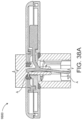
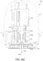
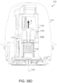
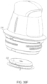
- FIGS. 3A-3D depict an example embodiment of an assembly process for sensor control device 102 by a user, including preparation of separate components before coupling the components in order to ready the sensor for delivery.
- FIG. 3A is a proximal perspective view depicting an example embodiment of a user preparing a container 810, configured here as a tray (although other packages can be used), for an assembly process.
- the user can accomplish this preparation by removing lid 812 from tray 810 to expose platform 808, for instance by peeling a non-adhered portion of lid 812 away from tray 810 such that adhered portions of lid 812 are removed. Removal of lid 812 can be appropriate in various embodiments so long as platform 808 is adequately exposed within tray 810. Lid 812 can then be placed aside.
- FIG. 3B is a side view depicting an example embodiment of a user preparing an applicator device 150 for assembly.
- Applicator device 150 can be provided in a sterile package sealed by a cap 708.
- Preparation of applicator device 150 can include uncoupling housing 702 from cap 708 to expose sheath 704 ( FIG. 3C ). This can be accomplished by unscrewing (or otherwise uncoupling) cap 708 from housing 702. Cap 708 can then be placed aside.
- FIG. 3C is a proximal perspective view depicting an example embodiment of a user inserting an applicator device 150 into a tray 810 during an assembly.
- the user can insert sheath 704 into platform 808 inside tray 810 after aligning housing orienting feature 1302 (or slot or recess) and tray orienting feature 924 (an abutment or detent).
- Inserting sheath 704 into platform 808 temporarily unlocks sheath 704 relative to housing 702 and also temporarily unlocks platform 808 relative to tray 810.
- removal of applicator device 150 from tray 810 will result in the same state prior to initial insertion of applicator device 150 into tray 810 (i.e., the process can be reversed or aborted at this point and then repeated without consequence).
- Sheath 704 can maintain position within platform 808 with respect to housing 702 while housing 702 is distally advanced, coupling with platform 808 to distally advance platform 808 with respect to tray 810. This step unlocks and collapses platform 808 within tray 810. Sheath 704 can contact and disengage locking features (not shown) within tray 810 that unlock sheath 704 with respect to housing 702 and prevent sheath 704 from moving (relatively) while housing 702 continues to distally advance platform 808. At the end of advancement of housing 702 and platform 808, sheath 704 is permanently unlocked relative to housing 702. A sharp and sensor (not shown) within tray 810 can be coupled with an electronics housing (not shown) within housing 702 at the end of the distal advancement of housing 702. Operation and interaction of the applicator device 150 and tray 810 are further described below.
- FIG. 3D is a proximal perspective view depicting an example embodiment of a user removing an applicator device 150 from a tray 810 during an assembly.
- a user can remove applicator 150 from tray 810 by proximally advancing housing 702 with respect to tray 810 or other motions having the same end effect of uncoupling applicator 150 and tray 810.
- the applicator device 150 is removed with sensor control device 102 (not shown) fully assembled (sharp, sensor, electronics) therein and positioned for delivery.
- FIG. 3E is a proximal perspective view depicting an example embodiment of a patient applying sensor control device 102 using applicator device 150 to a target area of skin, for instance, on an abdomen or other appropriate location .
- Advancing housing 702 distally collapses sheath 704 within housing 702 and applies the sensor to the target location such that an adhesive layer on the bottom side of sensor control device 102 adheres to the skin.
- the sharp is automatically retracted when housing 702 is fully advanced, while the sensor (not shown) is left in position to measure analyte levels.
- FIG. 3F is a proximal perspective view depicting an example embodiment of a patient with sensor control device 102 in an applied position. The user can then remove applicator 150 from the application site.
- System 100 can provide a reduced or eliminated chance of accidental breakage, permanent deformation, or incorrect assembly of applicator components compared to prior art systems. Since applicator housing 702 directly engages platform 808 while sheath 704 unlocks, rather than indirect engagement via sheath 704, relative angularity between sheath 704 and housing 702 will not result in breakage or permanent deformation of the arms or other components. The potential for relatively high forces (such as in conventional devices) during assembly will be reduced, which in turn reduces the chance of unsuccessful user assembly.
- FIG. 4A is a side view depicting an example embodiment of an applicator device 150 coupled with screw cap 708. This is an example of how applicator 150 is shipped to and received by a user, prior to assembly by the user with a sensor.
- FIG. 4B is a side perspective view depicting applicator 150 and cap 708 after being decoupled.
- FIG. 4C is a perspective view depicting an example embodiment of a distal end of an applicator device 150 with electronics housing 706 and adhesive patch 105 removed from the position they would have retained within sensor carrier 710 of sheath 704, when cap 708 is in place.
- the applicator device 20150 can be provided to a user as a single integrated assembly.
- FIGs. 4D and 4E provide perspective top and bottom views, respectively, of the applicator device 20150
- FIG. 4F provides an exploded view of the applicator device 20150
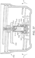
- FIG. 4G provides a side cut-away view.
- the perspective views illustrate how applicator 20150 is shipped to and received by a user.
- the exploded and cut-away views illustrate the components of the applicator device 20150.
- the applicator device 20150 can include a housing 20702, gasket 20701, sheath 20704, sharp carrier 201102, spring 205612, sensor carrier 20710 (also referred to as a "puck carrier”), sharp hub 205014, sensor control device (also referred to as a "puck") 20102, adhesive patch 20105, desiccant 20502, cap 20708, serial label 20709, and tamper evidence feature 20712. As received by a user, only the housing 20702, cap 20708, tamper evidence feature 20712, and label 20709 are visible.
- the tamper evidence feature 20712 can be, for example, a sticker coupled to each of the housing 20702 and the cap 20708, and tamper evidence feature 20712 can be damaged, for example, irreparably, by uncoupling housing 20702 and cap 20708, thereby indicating to a user that the housing 20702 and cap 20708 have been previously uncoupled.
- FIG. 5 is a proximal perspective view depicting an example embodiment of a tray 810 with sterilization lid 812 removably coupled thereto, which may be representative of how the package is shipped to and received by a user prior to assembly.
- FIG. 6A is a proximal perspective cutaway view depicting sensor delivery components within tray 810.
- Platform 808 is slidably coupled within tray 810.
- Desiccant 502 is stationary with respect to tray 810.
- Sensor module 504 is mounted within tray 810.
- FIG. 6B is a proximal perspective view depicting sensor module 504 in greater detail.
- retention arm extensions 1834 of platform 808 releasably secure sensor module 504 in position.
- Module 2200 is coupled with connector 2300, sharp module 2500 and sensor (not shown) such that during assembly they can be removed together as sensor module 504.
- FIG. 7A is side view depicting an example embodiment of the applicator housing 702 that can include an internal cavity with support structures for applicator function.
- a user can push housing 702 in a distal direction to activate the applicator assembly process and then also to cause delivery of sensor control device 102, after which the cavity of housing 702 can act as a receptacle for a sharp.
- various features are shown including housing orienting feature 1302 for orienting the device during assembly and use.
- Tamper ring groove 1304 can be a recess located around an outer circumference of housing 702, distal to a tamper ring protector 1314 and proximal to a tamper ring retainer 1306.
- Tamper ring groove 1304 can retain a tamper ring so users can identify whether the device has been tampered with or otherwise used.
- Housing threads 1310 can secure housing 702 to complimentary threads on cap 708 ( FIGS. 4A and 4B ) by aligning with complimentary cap threads and rotating in a clockwise or counterclockwise direction.
- a side grip zone 1316 of housing 702 can provide an exterior surface location where a user can grip housing 702 in order to use it.
- Grip overhang 1318 is a slightly raised ridge with respect to side grip zone 1316 which can aid in ease of removal of housing 702 from cap 708.
- a shark tooth 1320 can be a raised section with a flat side located on a clockwise edge to shear off a tamper ring (not shown), and hold tamper ring in place after a user has unscrewed cap 708 and housing 702.
- four shark teeth 1320 are used, although more or less can be used as desired.
- FIG. 7B is a perspective view depicting a distal end of housing 702.
- three housing guide structures (or “guide ribs”) 1321 are located at 120 degree angles with respect to each other and at 60 degree angles with respect to locking structures (or “locking ribs”) 1340, of which there are also three at 120 degree angles with respect to each other.
- Other angular orientations either symmetric or asymmetric, can be used, as well as any number of one or more structures 1321 and 1340.
- each structure 1321 and 1340 is configured as a planar rib, although other shapes can be used.
- Each guide rib 1321 includes a guide edge (also called a "sheath guide rail") 1326 that can pass along a surface of sheath 704 (e.g., guide rail 1418 described with respect to FIG. 8A ).
- An insertion hard stop 1322 can be a flat, distally facing surface of housing guide rib 1321 located near a proximal end of housing guide rib 1321. Insertion hard stop 1322 provides a surface for a sensor carrier travel limiter face 1420 of a sheath 704 ( FIG. 8B ) to abut during use, preventing sensor carrier travel limiter face 1420 from moving any further in a proximal direction.
- a carrier interface post 1327 passes through an aperture 1510 ( FIG. 9A ) of sensor carrier 710 during an assembly.
- a sensor carrier interface 1328 can be a rounded, distally facing surface of housing guide ribs 1321 which interfaces with sensor carrier 710.
- FIG. 7C is a side cross-section depicting an example embodiment of a housing.
- Locking rib 1340 includes sheath snap lead-in feature 1330 near a distal end of locking rib 1340 which flares outward from central axis 1346 of housing 702 distally.
- Each sheath snap lead-in feature 1330 causes detent snap round 1404 of detent snap 1402 of sheath 704 as shown in FIG. 8C to bend inward toward central axis 1346 as sheath 704 moves towards the proximal end of housing 702.
- detent snap 1402 of sheath 704 is locked into place in locked groove 1332.
- detent snap 1402 cannot be easily moved in a distal direction due to a surface with a near perpendicular plane to central axis 1346, shown as detent snap flat 1406 in FIG. 8C .
- detent snaps 1402 shift into the unlocked grooves 1334, and applicator 150 is in an "armed" position, ready for use.
- detent snap 1402 passes over firing detent 1344. This begins a firing sequence (as described, for example, with respect to FIGS.
- detent snap 1402 due to release of stored energy in the deflected detent snaps 1402, which travel in a proximal direction relative to the skin surface, toward sheath stopping ramp 1338 which is slightly flared outward with respect to central axis 1346 and slows sheath 704 movement during the firing sequence.
- sheath stopping ramp 1338 which is slightly flared outward with respect to central axis 1346 and slows sheath 704 movement during the firing sequence.
- the next groove encountered by detent snap 1402 after unlocked groove 1334 is final lockout groove 1336 which detent snap 1402 enters at the end of the stroke or pushing sequence performed by the user.
- Final lockout recess 1336 can be a proximally-facing surface that is perpendicular to central axis 1346 which, after detent snap 1402 passes, engages a detent snap flat 1406 and prevents reuse of the device by securely holding sheath 704 in place with respect to housing 702. Insertion hard stop 1322 of housing guide rib 1321 prevents sheath 704 from advancing proximally with respect to housing 702 by engaging sensor carrier travel limiter face 1420.
- FIGS. 7D and 7E are close-up side views of an example embodiment of locking rib 1340 of applicator housing 702, as detent snap 1402 of sheath 704 moves toward the proximal end of housing 702.
- FIG. 7D shows sheath 704 in a "locked” state, in which detent round 1404 of detent snap 1402 has already passed over sheath snap lead-in feature 1330 and is positioned in locked groove 1332 of locking rib 1340.
- detent round 1404 is advanced proximally into unlocked groove 1334, placing applicator 150 into an "armed" position.
- applicator 150 When force is further applied to the proximal end of housing 702, applicator 150 is "fired,” as detent round 1404 is advanced proximally from the unlocked groove 1334 and passes over firing detent 1344. Thereafter, sheath 704 is further advanced proximally such that detent round 1404 is slidably advanced over firing surface 1337, as shown in FIG. 7E .
- firing surface 1337 is substantially parallel to central axis 1346.
- detent round 1404 reaches sheath stopping ramp 1338 which slows the movement of sheath 704.
- detent snap flat 1406 (not shown) is engaged and securely holds sheath 704 in place with respect to housing 702.
- FIGS. 7F and 7G are close-up side views of an alternative embodiment of locking rib 2340 that is designed to improve the firing velocity of the sharp from the sensor applicator.
- locking rib 2340 includes an inward detent ramp 2335 to reduce friction between sheath 704 and housing 2702 during firing.
- Locking rib 2340 also includes a sheath stopping ramp 2338 at the proximal end of firing surface 2337.
- sheath 704 is initially shown in a "locked" state, in which detent round 1404 of detent snap 1402 has already passed over sheath snap lead-in feature 2330, and is positioned in locked groove 2332.
- detent round 1404 As force is applied to the proximal end of housing 2702, detent round 1404 is advanced into unlocked groove 2334, placing applicator 150 into the "armed” position. When force is further applied to the proximal end of housing 2702, applicator 150 is "fired,” as detent round 1404 passes over firing detent 2344.
- detent round 1404 then advances toward the proximal end of housing 2702 in a "free flight" state, in which detent round 1404 passes over inward detent ramp 2335. While advancing proximally in the "free flight” state, detent round 1404 can be in noncontinuous, or have no contact with, inward detent ramp 2335 and firing surface 2337. In this regard, detent round 1404 can be easily and quickly advanced, as there is little to no frictional force between detent round 1404 and inward detent ramp 2335 and firing surface 2337, and as such, improves upon the firing velocity of the sharp from the applicator.
- Sheath stopping ramp 2338 which is positioned proximally further along the locking rib 2340 relative to the embodiment shown in FIGS. 7D and 7E , provides an edge portion to frictionally engage the detent round 1404 and slow the movement of sheath 704.
- the sheath stopping ramp 2338 can have a sloped shape and provide for increasing frictional contact as the detent round 1404 advances in a proximal direction.
- detent snap flat 1406 (not shown) is engaged and securely holds sheath 704 in place with respect to housing 2702.
- Lockout recess 2336 prevents detent round 1404 and sheath 704 from backwards, or distal movement. This embodiment reflects a higher firing velocity relative to the embodiment depicted in FIGS. 7D and 7E , which also assists in prevention of a premature withdrawal of sharp.
- FIG. 7H is a close-up side view of an alternative embodiment of locking rib 6340 designed to maintain a downward force on sheath 6704 during firing which, in turn, can prevent sheath 6704 from unwanted movement during the sensor insertion process.
- sheath 6704 is shown in a "locked” state, in which detent round 6404 of detent snap 6402 is positioned in locked groove 6332 As force is applied to the proximal end of housing 6702, detent round 6404 is advanced into unlocked groove 6334, placing applicator in the "armed" position.
- detent round 6404 advances over sloped firing surface 6338 toward the proximal end of housing 6702. Sloped firing surface 6338 can be angled toward central axis 1346 such that the resulting downward force upon sheath 6704 increases as detent round 6404 advances in a proximal direction.
- detent round 6404 is in continuous contact with sloped firing surface 6338.
- Lockout recess 6336 prevents detent round 6404 and sheath 6704 from backwards, or distal movement.
- This embodiment reflects a slower firing velocity relative to the previously described embodiments, and can be used, for example, with the motion-actuated sharp retraction process that is described with respect to FIGS. 14A -14C and 15A-15B .
- FIG. 7I is a close-up side view of still another alternative embodiment of locking rib 7340, also designed to maintain a downward force on sheath 6704 during firing which, in turn, can prevent sheath 6704 from unwanted movement during a sensor insertion process.
- sheath 6704 is shown in a "fired" state, in which detent round 6404 of detent snap 6402 is positioned in a two-way lockout recess 7336.
- detent round 6404 advancing into two-way lockout recess 7336, sheath 6704 can be prevented from further movement in either a proximal or distal direction. This can reduce unwanted movement of sheath 6704 during the sensor insertion process.
- two-way lockout recess 7336 can provide for the immobilization of sheath 6704 during a motion-actuated sharp retraction process.
- sloped firing surface 7338 is angled toward central axis 1346 such that a resulting downward force upon sheath 6704 increases as detent round 6404 advances in a proximal direction.
- detent round 6404 is in continuous contact with sloped firing surface 7338. This embodiment reflects a slower firing velocity and can be used, for example, with the motion-actuated sharp retraction process that is described with respect to FIGS. 14A -14C and 15A-15B .
- housing 20702 in accordance with the disclosed subject matter is provided.
- Housing 20702 can be made of cyclic olefin copolymer, or other suitable materials, such as PolyCarbonate or high density poly ethylene (HDPE).
- Housing 20702 can include one or more of the features described herein with regard to housings, wherein similar features can operate as described herein.
- housing 20702 can include a grip overhang 20702A that can enable a user to securely grip housing 20702.
- the housing 20702 can have additional grip overhangs 20702A, for example, two grip overhands 20702A on opposite sides of the housing 20702.
- the housing 20702 can include a side grip zone 20702B disposed below the grip overhand 20702A.
- the side grip zone 20702B can be textured for improved gripping by a user.
- the housing 20702 can have additional side grip zones 20702B, for example, two side grip zones 20702B on opposite sides of the housing 20702, each disposed below a grip overhang 20702A.
- the housing 20702 can include a housing skirt 20702C, which can provide a surface for tamper evidence feature 20712.
- the housing skirt 20702C can be supported by a plurality of skirt stiffening ribs 20702D.
- the skirt stiffening ribs 20702D can provide support for the housing skirt 20702C and can help protect the applicator device 20150 during a shock event, such as a drop. Additionally, the skirt stiffening ribs 20702D can be used to support the housing 20702 during manufacturing.
- the housing skirt 20702C and skirt stiffening ribs 20702D can provide stiffness against forces due to gasket compression, and can help maintain gasket 20701 compression through shelf life.
- the housing 20702 can include a gasket retention ring 20702E and a plurality of gasket retention pockets 20702F, which can hold the gasket 20701 relative the housing 20702.
- the gasket retention ring 20702E can prevent lateral and/or axial movement of the gasket 20701, and the gasket retention pockets 20702E can prevent rotation of the gasket 20701.
- the housing 20702 can include a plurality of gasket retention pockets, for example, 14 gasket retention pockets 20702E.
- Gasket sealing face 20702N that can seal against the gasket 20701.
- Housing 20702 can additionally or alternatively have an applicator cap sealing lip 20702U that can interface with the cap 20708, as described in greater detail below.
- Housing 20702 can have inner surface 20702T that can receive the sheath 20704.
- Housing 20702 can include threads 20702G configure to engage with threads 20708D disposed on cap 20708.
- the threads can include radial limiting features 20702H, which can limit radial deformation of the cap 20702 (e.g., 20708D, 20708F, and 20708G) during a shock event, such as a drop.
- Housing 20702 can include a plurality of radial limiting features 20702H, for example, 6 radial limiting features 20702H.
- the radial limiting features 20702H can be protrusions from the housing and can close a gap with the threads 20708D disposed on cap 20708.
- Housing 20702 can further include a clearance notch 20702I for clearance of the sheath arms during firing.
- housing 20702 can include a plurality of sensor carrier attachment features for receiving, aligning, and limiting movement of the sensor carrier 20710.
- housing 20703 can include sheath guide rails 20702J, which can help to align and guide sheath 20704 as the sheath 20704 moves relative the housing 20702.
- Housing 20702 can include sensor carrier attach slots 20702K, which can engage and hold the sensor carrier 20710, and sensor carrier hard stops 20702L, that can limit axial movement of the sensor carrier 20710 relative the housing 20702.
- Housing 20702 can include sensor carrier biasing feature 20702M that can remove slop between the sensor carrier 20710 and the housing 20702 after assembly and sensor carrier radial limiting feature 207020 that can keep the sensor carrier radially aligned relative the housing 20702.
- Flat horizontal faces between sensor carrier attach slots 20702K and sensor carrier radial limiting feature 207020 can be used to stop the sheath 20704 at the end of a stroke. Corresponding features on the sheath 20704 can interact with these faces.
- the sensor carrier biasing feature 20702M can further limit rotation of the sensor carrier 20710 relative the housing 20702.
- Housing 20702 can include one or more of each of the sheath guide rails 20702J, sensor carrier attach slots 20702K, sensor carrier hard stops 20702L, sensor carrier radial limiting feature 207020, and sensor carrier biasing feature 20702M, for example, three of each.
- housing 20702 can further include a plurality sheath ribs 20702S for engaging the sheath 20704 for insertion, as described herein.
- Housing 20702 can include one or more of sheath ribs 20702S, for example, three.
- Each sheath rib 20702S can include a sheath snap lead in feature 20702P configured to initially lead in the detent snap 20704A of sheath 20704 into the correct location.
- the housing 20702 can include a firing detent 20702Q. After the detent snap 20704A of sheath 20704 passes the firing detent 20702Q, the firing sequence can be initiated, and the sheath 20704 can travel toward the sheath stopping ramp 20702R. The sheath stopping ramp 20702 can slow the sheath 20704 at the end of firing.
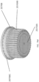
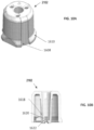
- Cap 20708 can include one or more of the features described herein with regard to caps, wherein similar features can operate as described herein.
- Cap 20708 can be made of high density polyethylene (HDPE) or any other suitable materials, such as PolyPropylene or low-density polyethylene (LDPE).
- Cap 20708 can include a label surface 20708A configured to receive label 20709.
- Cap 20708 can include ribs 20708B which can provide strength and provide an improved gripping surface for a user.
- the cap 20708 can include tamper label ring 20708C, which can receive the tamper evidence feature 20712.
- the cap 20708 can also include a gasket sealing surface 20708G, configured to engage gasket 20701.
- cap 20708 can include threads 20708D, which can engage threads 20702G disposed on the housing 20702.
- Cap 20708 can also include seal interface 20708E which can be configured to receive the applicator cap sealing lip 20702U to create a seal between the housing 20702 and the cap 20708.
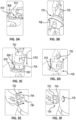
- FIGS. 7P-S show an enlarged cross-sectional side view of the interface between housing 20702 and cap 20708.
- applicator cap sealing lip 20702U of housing 20702 includes a first axial extension 2002a and seal interface 20708E of cap 20708 provides a cavity 2002d matable with the first axial extension 2002a.
- the diameter of cavity 2002d formed from second axial extension 2002b and third axial extension 2002c of the cap 20708 is sized to receive the diameter of first axial extension 2002a of housing 20702 within cavity 2002d.
- axial extension 2002a can have thickness D1 at height H1, as measured from distal edge of axial extension 2002a.
- second axial extension 2002c can have a thickness D5 at height H3, as measured from proximal edge of cap 20708; cavity 2002d can have a thickness D2, D3, and D4 at heights H2, H3, and H4, respectively, as measured from proximal edge of cap 20708.
- D1 can measure 1mm with a tolerance of +/- 0.03mm
- D2, D3, D4 can have any suitable dimensions
- H1 can measure 1.66mm with a tolerance of +/- 0. 1mm
- H2 can measure 8.25mm with a tolerance of +/- 0.1mm
- H3 can measure 9.25mm with a tolerance of +/- 0.1mm
- H4 can measure 9.75mm with a tolerance of +/- 0.1mm.
- the reverse can be employed, where the diameter of first axial extension 2002a can be sized to receive the diameter of the second axial extension 2002b, without departing from the scope of the disclosure.
- two radial seals 2004, 2006 can be defined or otherwise provided at the interface between first and second axial extensions 2002a, b and radial seals 2004 and 2006 can help prevent migration of fluids or contaminants across the interface in either axial direction.
- the dual radial seals described herein can accommodate tolerance and thermal variations combined with stress relaxation via a redundant sealing strategy.
- dual radial seals 2004, 2006 utilize a "wedge" effect for effective sealing between first axial extension 2002a and second axial extension 2002b.
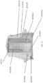
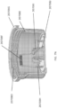
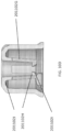
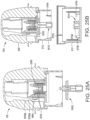
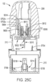
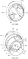
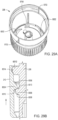
- Cap 20708 can include one or more sets of ribs 20708F (see FIG. 7N ), for example, two sets of ribs 20708F, wherein ribs 20708F can comprise crush ribs.
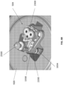
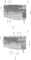
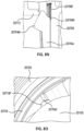
- the crush ribs 20708F can be configured to engage the edge 20704N of lock arm 20704J during a shock event, for example a drop, as described in greater detail below (see e.g., FIG. 8N ).
- edge 20704N can be a sharp edge.
- Cap 20708 can include one or more desiccant retention clips 20708H to retain the desiccant 20502 in the cap 20708 and limit rotation of the desiccant 20502.
- Cap 20708 can include a ratchet 20708I to engage the sensor cap and remove the sensor cap when the cap 20708 is removed from the housing 20702, as described in greater detail below
- Cap 20708 can include a plurality of ribs 20708J to provide strength.
- cap 20708 can include one or more surfaces to engage other elements in the applicator device 20150 to provide support or limit movement in the case of a shock event, for example, a drop.
- the cap can include a sheath support surface 20708K, configured to support the sheath 20704 during a shock event.
- the sheath support surface 20708K can limit distal movement of the sheath 20704 during a shock event. This can lead to less stress on the sensor carrier 20710 and the sensor control device 20102 and can reduce the risk of the sensor control device 20102 dislodging from the sensor carrier 20710.
- the cap 20708 can include a raised ridge 20708L.
- the raised ridge 20708F can interface with a plug, such as an elastomeric plug 9130A (which can be coupled to, e.g., a sensor cap or a desiccant cap).
- the raised ridge 20708L can thereby also support the sharp carrier 1102, sensor carrier 20710, sensor control device 20102, and accordingly, can prevent dislodging of the sensor control device 20102 from the sensor carrier 20710 during a shock event.
- additional support on the elastomeric plug 9130A and other features can increase the stress on various seals in the applicator device 20150, and thereby improve the seals prior to removing the cap 20708 from the housing.
- FIGS. 8A and 8B are a side view and perspective view, respectively, depicting an example embodiment of sheath 704.
- sheath 704 can stage sensor control device 102 above a user's skin surface prior to application.
- Sheath 704 can also contain features that help retain a sharp in a position for proper application of a sensor, determine the force required for sensor application, and guide sheath 704 relative to housing 702 during application.
- Detent snaps 1402 are near a proximal end of sheath 704, described further with respect to FIG. 8C below.
- Sheath 704 can have a generally cylindrical cross section with a first radius in a proximal section (closer to top of figure) that is shorter than a second radius in a distal section (closer to bottom of figure). Also shown are a plurality of detent clearances 1410, three in the example embodiment. Sheath 704 can include one or more detent clearances 1410, each of which can be a cutout with room for sheath snap lead-in feature 1330 to pass distally into until a distal surface of locking rib 1340 contacts a proximal surface of detent clearance 1410.
- Guide rails 1418 are disposed between sensor carrier traveler limiter face 1420 at a proximal end of sheath 704 and a cutout around lock arms 1412. Each guide rail 1418 can be a channel between two ridges where the guide edge 1326 of housing guide rib 1321 can slide distally with respect to sheath 704.
- Lock arms 1412 are disposed near a distal end of sheath 704 and can include an attached distal end and a free proximal end, which can include lock arm interface 1416. Lock arms 1412 can lock sensor carrier 710 to sheath 704 when lock arm interface 1416 of lock arms 1412 engage lock interface 1502 of sensor carrier 710. Lock arm strengthening ribs 1414 can be disposed near a central location of each lock arm 1412 and can act as a strengthening point for an otherwise weak point of each lock arm 1412 to prevent lock arm 1412 from bending excessively or breaking.
- Detent snap stiffening features 1422 can be located along the distal section of detent snaps 1402 and can provide reinforcement to detent snaps 1402.
- Alignment notch 1424 can be a cutout near the distal end of sheath 704, which provides an opening for user alignment with sheath orientation feature of platform 808.
- Stiffening ribs 1426 can include buttresses, that are triangularly shaped here, which provide support for detent base 1436.
- Housing guide rail clearance 1428 can be a cutout for a distal surface of housing guide rib 1321 to slide during use.
- FIG. 8C is a close-up perspective view depicting an example embodiment of detent snap 1402 of sheath 704.
- Detent snap 1402 can include a detent snap bridge 1408 located near or at its proximal end.
- Detent snap 1402 can also include a detent snap flat 1406 on a distal side of detent snap bridge 1408.
- An outer surface of detent snap bridge 1408 can include detent snap rounds 1404 which are rounded surfaces that allow for easier movement of detent snap bridge 1408 across interior surfaces of housing 702 such as, for example, locking rib 1340.
- FIG. 8D is a side view depicting an example embodiment of sheath 704.
- alignment notch 1424 can be relatively close to detent clearance 1410.
- Detent clearance 1410 is in a relatively proximal location on distal portion of sheath 704.
- FIG. 8E is an end view depicting an example embodiment of a proximal end of sheath 704.
- a back wall for guide rails 1446 can provide a channel to slidably couple with housing guide rib 1321 of housing 702.
- Sheath rotation limiter 1448 can be notches which reduce or prevent rotation of the sheath 704.
- FIGS. 8F-8H are perspective views of an alternative example embodiment of sheath 6704 in various stages of assembly with other components of the applicator.
- sheath 6704 can have many of the same features as sheath 704, previously described with respect to FIGS. 8A-8C .
- Sheath 6704 can include one or more detent snaps 6404 having one or more detent rounds 6402 attached thereto.
- Sheath 6704 can be shorter in overall length as compared to sheath 702.
- sheath 6704 can include one or more inner sheath ribs 6425 disposed on the inner surface of sheath 6704, and which protrude in an inward direction towards the central axis of sheath 6704.
- sheath 6704 is shown in perspective view in a stage of assembly with applicator housing 6702 and sensor carrier 6710.
- One or more inner sheath ribs 6425 of sheath 6704 can interface with one or more corresponding rib notches 6519 in sensor carrier 6710.
- the fitted interface between corresponding ribs 6425 and notches 6519 can help maintain axial alignment of the sheath 6704 and sensor carrier 6710 during the sensor insertion process.
- the interface between ribs 6425 and notches 6519 can reduce lateral and rotational movement between the applicator components, which can, in turn, reduce the chance of improper sensor insertion.
- sheath 6704 is shown in perspective view in a stage of assembly with applicator housing 6702 and sensor electronics housing 706, which has been inserted into sensor carrier 6710. Inner sheath ribs 6425 are also shown.
- ribs 6425 and 64 corresponding rib notches 6519 are depicted, any number of ribs and notches are fully within the scope of the present disclosure.
- ribs 6425 are depicted with a rounded surface edge, in other embodiments, ribs 6425 can have a rectangular or triangular shape, and rib notches 6519 can have a corresponding receiving shape for interfacing with ribs 6425.
- ribs 6425 are depicted as being disposed on an inner circumferential surface of sheath 6704, ribs 6425 can also be disposed on any other surface of sheath 6704, or portion thereof, that comes into contact with sensor carrier 6710.
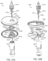
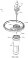
- a sheath 20704 is provide, in accordance with the disclosed subject matter.
- Sheath 20704 can be made of Delrin or other suitable materials, for example, other low friction polymers.
- Sheath 20704 can include one or more of the features described herein with regard to sheaths, wherein similar features can operate as described herein.
- sheath 20704 can include detent snaps 20704A having a free proximal end, configured to engage the sheath ribs 20702S during firing.
- Fig. 8J shows a close up of the free proximal end of detent snap 20704A.
- the detent snaps 20704A can include a round portion 20704B, for engagement with the sheath ribs 20702S and a flat portion 20704C for final lockout on housing 20704 after use.
- the round portion 20704B can include a parting line mismatch 20704D that can prevent a force spike during firing.
- the detent snaps 20704A can be coupled to the sheath 20704 at an enlarged distal portion 20704E, which can provide support to the detent snap 20704.
- Sheath 20704 can include a plurality of detent snaps 20704A, for example, three.
- the sheath 20704 can include one or more, for example, three, housing clearances 20704F, which can allow the sheath 20704 to clear the housing 20702 at the end of firing.
- sheath 20704 can further include a plurality of stiffening ribs 20704P (e.g., six) which can stiffen the sheath 20704.
- Sheath 20704 can include a plurality of guides 20704G for engaging the sheath guide rails 20702J of the housing 20702.
- Sheath 20704 can further include a slot 20704H including a stop 20704I at a distal end of the slot 20704H configured to engage the sheath guide rails 20702J of the sheath 20702 to limit further proximal movement of the sheath 20704 relative the housing 20702 at the end of firing.
- Sheath 20704 can also include a clearance 20704T for clearing the sensor carrier biasing feature 20702I disposed on the sheath guide rails 20702J of the housing 20702.
- sheath 20704 can include lock arms 20704J.
- Lock arms 20704J can be configured to engage the sensor carrier 20710 and limit movement of the sensor carrier 20710 or sheath 20704 prior to firing.
- the lock arms 20704J can include a free proximal end 20704K and an attached distal end 20704L.
- the free proximal end 20704K can include a lock arm interface 20704M disposed on an inner surface of the lock arm 20704J.
- the lock arm interface 20704M can engage a lock ledge 20710N on the sensor carrier 20710.
- the cap 20708 when cap 20708 is coupled to housing 20702, the cap 20708 can urge the lock arm 20704J inwardly, and can cause the lock arm interface 20704M to engage the sensor carrier 20710. That is, the lock arms 20704J can wedge between the cap 20708 and the sensor carrier 20710. Accordingly, the lock arm 20704J can limit proximal movement of the sheath 20704 when the cap 20708 is coupled to the housing 20702. Such engagement can limit movement of the sheath 20704 during a shock event, such as a drop.
- the lock arm interface 20704M can have a triangle shape when viewed in side view (e.g., FIG.
- the shape of the lock arm interface 20704M can provide benefits during manufacturing.
- the shape of the lock arm interface 20704M can allow the sheath 20704 to be force ejected from a mold during manufacturing of the sheath 20704.
- Force ejecting the sheath 20704 can allow for a more a simplified manufacture process, for example, using a simplified core/cavity design, and can eliminate additional parting lines or the use of complicated lifters and/or slides to create undercut features in the plastic part.
- Parting lines can result in an unsmooth surface which can catch on the sensor carrier 20710 during firing and can result in potential spikes in firing force. Accordingly, using force ejection results in a simpler mold design facilitating a smoother lock arm interface 20704M and prevent potential spikes in firing force due to parting lines.
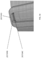
- the proximal free end of the lock arm 20704J can further include an edge 20704N (such as, e.g., a sharp edge) on an outer surface.
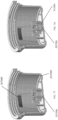
- the sharp edge 20704N can be configured to engage ribs 20708F (which can comprise, e.g., crush ribs) disposed on the cap 20708 during a shock event.
- the sharp edge 20704N can dig into the crush ribs 20708F and permanently deform the crush ribs 20708F, which can absorb energy during a shock event, and prevent sheath 20704 collapse.
- the shape lock arm interface 20704M can also be beneficial for drop protection.
- the ramp can force the lock arm 20704J to move radially as the sheath 20704 collapsed during a drop. This can force the sharp edge 20704N to dig into the crush ribs 20708F and can help to stop the sheath 20704 from collapsing.
- Sheath 20704 can include a plurality of lock arms 20704J, for example, two lock arms 20704J.
- sheath 20704 can include rib 20704U configured to engage a lock interface 20710F on a sensor retention arm 20710B on the sensor carrier 20710.
- the rib 20704U can prevent the sensor retention arm 20710B from flexing outwardly, for example, during a shock event, and therefore can prevent movement of the sensor control device 20102 during a shock event.
- Rib 20704U can have a height (i.e., in the longitudinal direction) selected such that even if the sheath 20704 moves proximally or distally during a shock event, the rib 20704U will continue to engage lock interface 2071 0F on a sensor retention arm 20710B on the sensor carrier 20710 and prevent the sensor control device 20102 from dislodging from the sensor carrier 20710.
- the sheath 20704 can include a noise damper 207040.
- the noise damper 207040 can be configured to engage the sharp carrier 201102 as the sharp carrier 201102 is retracted to slow movement of the sharp carrier 201102 and can thereby reduce noise produce by the sharp carrier 201102 engaging the sheath 20704.
- the noise damper 207040 includes an angled ramp extending from the inner surface of sheath 20704, but other suitable configurations can be used.
- sheath 20704 can include a slot 20704Q configured to receive sharp carrier retention feature 20710L disposed on the sensor carrier 20710 and to thereby permit partial retraction of the sharp carrier 201102 during deployment (as described in greater detail below).
- the sheath 20704 can also include cap lead-in 20704R, alignment notch 20704S and skin interface 20704T.
- FIG. 9A is a proximal perspective view depicting an example embodiment of sensor carrier 710 that can retain sensor electronics within applicator 150. It can also retain sharp carrier 2102 with sharp module 2500.
- sensor carrier 710 generally has a hollow round flat cylindrical shape, and can include one or more deflectable sharp carrier lock arms 1524 (e.g., three) extending proximally from a proximal surface surrounding a centrally located spring alignment ridge 1516 for maintaining alignment of spring 1104.
- Each lock arm 1524 has a detent or retention feature 1526 located at or near its proximal end.
- Shock lock 1534 can be a tab located on an outer circumference of sensor carrier 710 extending outward and can lock sensor carrier 710 for added safety prior to firing.
- Rotation limiter 1506 can be a proximally extending relatively short protrusion on a proximal surface of sensor carrier 710 which limits rotation of carrier 710.
- Sharp carrier lock arms 1524 can interface with sharp carrier 2102 as described with reference to FIGS. 10A -10E below.
- FIG. 9B is a distal perspective view of sensor carrier 710.
- one or more sensor electronics retention spring arms 1518 are normally biased towards the position shown and include a detent 1519 that can pass over the distal surface of electronics housing 706 of device 102 when housed within recess or cavity 1521.
- the user pulls applicator 150 in a proximal direction, i.e., away from the skin.
- the adhesive force retains sensor control device 102 on the skin and overcomes the lateral force applied by spring arms 1518.
- spring arms 1518 deflect radially outwardly and disengage detents 1519 from sensor control device 102 thereby releasing sensor control device 102 from applicator 150.
- FIG. 9C is a perspective view of an alternative example embodiment of sensor carrier 6710.
- sensor carrier 6710 can have many of the same features as sensor carrier 710, previously described with respect to FIGS. 9A-9B .
- sensor carrier 6710 also includes one or more notch ribs 6519 disposed along an outer circumferential surface. As best seen in FIGS. 8F-8H , notch ribs 6519 are configured to interface with inner sheath ribs 6425 in order to maintain axial alignment of the sheath and sensor carrier, and reduce lateral and rotational movement between applicator components during the sensor insertion process.
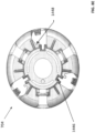
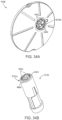
- Sensor carrier 20710 can include one or more of the features described herein with regard to sensor carriers, wherein similar features can operate as described herein.
- sensor carrier 20710 can include a base 20710A and first and second retention arms 20710B.
- Each retention arm 20710B can include a first end portion 20710C coupled to the base 20710A and a free end portion 20710D.
- each retention arm 20710B can be coupled to the base 20710A at a first half of the base 20710A and the free end portion 20710D can extend toward a second half of the base 20710A.
- Each retention arm 20710B can include a sensor retention feature 20710E disposed on an inner surface of the sensor retention arm 20710B.
- the sensor retention feature 20710E can be disposed on the free end portion 20710D.
- the sensor retention feature 20710E can be configured to retain the sensor control device 20102 within the housing 20702.
- the retention feature 20710E can include a conical surface and angular parting line, which can allow for release of the sensor control device 20102 upon delivery.
- Each retention arm 20710 can include a lock interface 20710F disposed on an outer surface of the retention arm 20710B.
- the lock interface 20710F can engage rib 20704U on the sheath 20704.
- the rib 20704U can prevent the sensor retention arm 20710B from flexing outwardly, for example, during a shock event, and therefore can keep retention feature 20710E engaged with the sensor control device 20102, and thereby prevent movement of the sensor control device 20102 during a shock event.
- Sensor carrier 20710 can include a plurality of housing attachment features 20710F1.
- sensor carrier 20710 can include three housing attachment features 20710F1.
- sensor carrier 20710 can include two, four, five, six, or more housing attachment features 20710F1.
- the housing attachment features 20710F1 can be equally spaced on the sensor carrier 20710 and can extend upwardly from a top surface of the sensor carrier 20710.
- Each sensor housing attachment feature 20710F1 can include a housing snap 20710G, housing locator feature 20710H, biasing feature 20710I, and housing stop 20710J.
- the housing locator feature 20710H can axially locate the sensor carrier 20710 relative the housing 20702 when the two are to be coupled together.
- the housing snap 20710G can engage the sensor carrier attach slots 20702K on the housing 20702 to couple the sensor carrier 20710 to the housing 20702.
- the biasing feature 20710I can engage sensor carrier biasing feature 20702M on housing 20702 configured to remove slop between the sensor carrier 20710 and the housing 20702.
- Housing stop 20710J can locate the sensor carrier 20710 axially relative to the housing 20702.
- Sensor carrier 20710 can further include a plurality of sharp carrier lock arms 20710K, for example three sharp carrier lock arms 20710K.
- the sharp carrier lock arms 20710K can be equally spaced on the sensor carrier 20710 and can extend upwardly form a top surface of the sensor carrier 20710.
- Each sharp carrier lock arm 20710K can include a sharp carrier retention feature 20710L and a rib 20710M. Rib 20710M can engage an inner surface of the sheath 20704, which can urge the sharp carrier lock arm 20710K inwardly and cause sharp carrier retention feature 20710L to retain sharp carrier 201102, as described in greater detail below.
- the carrier retention feature 20710L can have a triangle shape when viewed in side view and a "U" shape when viewed in top view.
- the sensor carrier 20710 can include a plurality of lock ledges 20710N configured to engage lock arm interface 20704M of the sheath 20704 as described herein above.
- the sensor carrier 20710 can include two lock ledges 20710N.
- Sensor carrier 20710 can include recesses 207100 disposed proximate each lock ledge 20710N and configured to receive the lock arm interface 20704M during firing, to prevent the lock arm 20704J from engaging with housing 20702 during firing.
- Sensor carrier 20710 can include a hole 20710P extending through a middle of the base 20710A. The hole 20710P can guide and limit movement of sharp hub 205014 during insertion. Additionally, or alternatively, sensor carrier 20710 can include spring locator 20710Q.
- a bottom surface of the sensor carrier 20710 can include stiffening ribs 20710R and sensor locator ribs 20710S, which can limit planar motion of the sensor control device 20102 relative the sensor carrier 20710.
- the bottom surface of the sensor carrier 20710 can include a sensor support surface 20710T configure to support the sensor control device 20102.
- FIGS. 10A and 10B are a proximal perspective view and a side cross-sectional view, respectively, depicting an example embodiment of sharp carrier 2102.
- Sharp carrier 2102 can grasp and retain sharp module 2500 within applicator 150. It can also automatically retract as a result of one or more springs changing from a preloaded, compressed state to an expanded state during an insertion process, as described with respect to FIGS. 40A-40F.
- Near a distal end of sharp carrier 2102 can be anti-rotation slots 1608 which prevent sharp carrier 2102 from rotating when located within a central area of sharp carrier lock arms 1524 (as shown in FIG. 9A ).
- Anti-rotation slots 1608 can be located between sections of sharp carrier base chamfer 1610, which can ensure full retraction of sharp carrier 2102 through sheath 704 upon retraction of sharp carrier 2102 at the end of the deployment procedure.
- sharp retention arms 1618 can be located in an interior of sharp carrier 2102 about a central axis and can include a sharp retention clip 1620 at a distal end of each arm 1618.
- Sharp retention clip 1620 can have a proximal surface which can be nearly perpendicular to the central axis and can abut a distally facing surface of sharp hub 2516 ( FIG. 17A ).
- Sharp carrier 201102 can include one or more features described herein with regard to sharp carriers, wherein similar features can operate as describe herein.
- sharp carrier 201102 can include a series of features for engaging with the three sharp carrier lock arms 20710K of the sensor carrier 20710.
- the features can include a pre-partial-retraction retention face 201102A and a post-partial-retraction retention face 201102B.
- the pre-partial retraction retention face 201102A can engage the sharp carrier retention feature 20710L prior to partial retraction, for example, during shipping and storage.
- Post-partial-retraction retention face 201102B can engage the sharp carrier retention feature 20710L after partial retraction.
- the rib 20710M of the retention arm 20710L can engage slot 20704Q of sheath 20704, which can allow the retention arm 20710L to move radially outward and allow sharp carrier retention feature 20710L to clear the pre-partial retraction retention face 201102A and engage the post-partial retraction retention face 201102B.
- a height between the end of the pre-partial-retraction face 201102A and the start of the post-partial-retraction face 201102B can be the distance of the partial retraction.
- a running face 201102C can be disposed below the post-partial-retraction retention face 201102B and can slide against the retention arm 20710L as the sharp carrier 201102 is retracted.
- Alignment walls 201102D can help to keep the sharp carrier 201102 aligned with the sensor carrier 20704 during partial retraction.
- Sharp carrier 201102 can include a chamfer 201102F, which can include anti-rotation slots 201102E to engage the retention arms 20710L on the sensor carrier 20710.
- sharp carrier 201102 can include sharp retention arms 201102G including lead-in face 201102I and sharp hub contact face 201102H.
- the retention arms 201102G can receive and hold sharp hub 205014.
- Spring stop 201102J can engage retraction spring 205612.
- FIGS. 11A and 11B are a top perspective view and a bottom perspective view, respectively, depicting an example embodiment of sensor module 504.
- Module 504 can hold a connector 2300 ( FIGS. 12A and 12B ) and a sensor 104 ( FIG. 13 ).
- Module 504 is capable of being securely coupled with electronics housing 706.
- One or more deflectable arms or module snaps 2202 can snap into the corresponding features 2010 of housing 706.
- a sharp slot 2208 can provide a location for sharp tip 2502 to pass through and sharp shaft 2504 to temporarily reside.
- a sensor ledge 2212 can define a sensor position in a horizontal plane, prevent a sensor from lifting connector 2300 off of posts and maintain sensor 104 parallel to a plane of connector seals. It can also define sensor bend geometry and minimum bend radius. It can limit sensor travel in a vertical direction and prevent a tower from protruding above an electronics housing surface and define a sensor tail length below a patch surface.
- a sensor wall 2216 can constrain a sensor and define a sensor
- FIGS. 12A and 12B are perspective views depicting an example embodiment of connector 2300 in an open state and a closed state, respectively.
- Connector 2300 can be made of silicone rubber that encapsulates compliant carbon impregnated polymer modules that serve as electrical conductive contacts 2302 between sensor 104 and electrical circuitry contacts for the electronics within housing 706.
- the connector can also serve as a moisture barrier for sensor 104 when assembled in a compressed state after transfer from a container to an applicator and after application to a user's skin.
- a plurality of seal surfaces 2304 can provide a watertight seal for electrical contacts and sensor contacts.
- One or more hinges 2208 can connect two distal and proximal portions of connector 2300.
- FIG. 13 is a perspective view depicting an example embodiment of sensor 104.
- a neck 2406 can be a zone which allows folding of the sensor, for example ninety degrees.
- a membrane on tail 2408 can cover an active analyte sensing element of the sensor 104.
- Tail 2408 can be the portion of sensor 104 that resides under a user's skin after insertion.
- a flag 2404 can contain contacts and a sealing surface.
- a biasing tower 2412 can be a tab that biases the tail 2408 into sharp slot 2208.
- a bias fulcrum 2414 can be an offshoot of biasing tower 2412 that contacts an inner surface of a needle to bias a tail into a slot.
- a bias adjuster 2416 can reduce a localized bending of a tail connection and prevent sensor trace damage.
- Contacts 2418 can electrically couple the active portion of the sensor to connector 2300.
- a service loop 2420 can translate an electrical path from a vertical direction ninety degrees and engage with sensor ledge
- FIGS. 14A and 14B are bottom and top perspective views, respectively, depicting an example embodiment of a sensor module assembly comprising sensor module 504, connector 2300, and sensor 104.
- sensor 104 can be subject to axial forces pushing up in a proximal direction against sensor 104 and into the sensor module 504, as shown by force, F1, of FIG. 14A . According to some embodiments, this can result in an adverse force, F2, being applied to neck 2406 of sensor 104 and, consequently, result in adverse forces, F3, being translated to service loop 2420 of sensor 104.
- axial forces, F1 can occur as a result of a sensor insertion mechanism in which the sensor is designed to push itself through the tissue, a sharp retraction mechanism during insertion, or due to a physiological reaction created by tissue surrounding sensor 104 (e.g., after insertion).
- FIGS. 15A and 15B are close-up partial views of an example embodiment of a sensor module assembly having certain axial stiffening features.
- the embodiments described herein are directed to mitigating the effects of axial forces on the sensor as a result of insertion and/or retraction mechanisms, or from a physiological reaction to the sensor in the body.
- sensor 3104 comprises a proximal portion having a hook feature 3106 configured to engage a catch feature 3506 of the sensor module 3504.
- sensor module 3504 can also include a clearance area 3508 to allow a distal portion of sensor 3104 to swing backwards during assembly to allow for the assembly of the hook feature 3106 of sensor 3104 over and into the catch feature 3506 of sensor module 3504.
- the hook and catch features 3106, 3506 operate in the following manner.
- Sensor 3104 includes a proximal sensor portion, coupled to sensor module 3504, as described above, and a distal sensor portion that is positioned beneath a skin surface in contact with a bodily fluid.
- the proximal sensor portion includes a hook feature 3106 adjacent to the catch feature 3506 of sensor module 3504.
- one or more forces are exerted in a proximal direction along a longitudinal axis of sensor 3104.
- hook feature 3106 engages catch feature 3506 to prevent displacement of sensor 3104 in a proximal direction along the longitudinal axis.
- sensor 3104 can be assembled with sensor module 3504 in the following manner.
- Sensor 3104 is loaded into sensor module 3504 by displacing the proximal sensor portion in a lateral direction to bring the hook feature 3106 in proximity to the catch feature 3506 of sensor module 3504. More specifically, displacing the proximal sensor portion in a lateral direction causes the proximal sensor portion to move into clearance area 3508 of sensor module 3504.
- FIGS. 15A and 15B depict hook feature 3106 as a part of sensor 3104, and catch feature 3506 as a part of sensor module 3504, those of skill in the art will appreciate that hook feature 3106 can instead be a part of sensor module 3504, and, likewise, catch feature 3506 can instead be a part of sensor 3106. Similarly, those of skill in the art will also recognize that other mechanisms (e.g., detent, latch, fastener, screw, etc.) implemented on sensor 3104 and sensor module 3504 to prevent axial displacement of sensor 3104 are possible and within the scope of the present disclosure.
- mechanisms e.g., detent, latch, fastener, screw, etc.
- FIG. 15C is a side view of an example sensor 11900, according to one or more embodiments of the disclosure.
- the sensor 11900 may be similar in some respects to any of the sensors described herein and, therefore, may be used in an analyte monitoring system to detect specific analyte concentrations.
- the sensor 11900 includes a tail 11902, a flag 11904, and a neck 11906 that interconnects the tail 11902 and the flag 11904.
- the tail 11902 includes an enzyme or other chemistry or biologic and, in some embodiments, a membrane may cover the chemistry.
- the tail 11902 is transcutaneously received beneath a user's skin, and the chemistry included thereon helps facilitate analyte monitoring in the presence of bodily fluids.
- the tail 11902 may be received within a hollow or recessed portion of a sharp (not shown) to at least partially circumscribe the tail 11902 of the sensor 11900. As illustrated, the tail 11902 may extend at an angle Q offset from horizontal. In some embodiments, the angle Q may be about 85°. Accordingly, in contrast to other sensor tails, the tail 11902 may not extend perpendicularly from the flag 11904, but instead at an angle offset from perpendicular. This may prove advantageous in helping maintain the tail 11902 within the recessed portion of the sharp.
- the tail 11902 includes a first or bottom end 11908a and a second or top end 11908b opposite the bottom end 11908a.
- a tower 11910 may be provided at or near the top end 11908b and may extend vertically upward from the location where the neck 11906 interconnects the tail 11902 to the flag 11904. During operation, if the sharp moves laterally, the tower 11910 will help pivot the tail 11902 toward the sharp and otherwise stay within the recessed portion of the sharp.
- the tower 11910 may provide or otherwise define a protrusion 11912 that extends laterally therefrom.
- the protrusion 11912 may engage the inner surface of the recessed portion. In operation, the protrusion 11912 may help keep the tail 11902 within the recessed portion.
- the flag 11904 may comprise a generally planar surface having one or more sensor contacts 11914 arranged thereon.
- the sensor contact(s) 11914 may be configured to align with a corresponding number of compliant carbon impregnated polymer modules encapsulated within a connector.
- the neck 11906 may provide or otherwise define a dip or bend 11916 extending between the flag 11904 and the tail 11902.
- the bend 11916 may prove advantageous in adding flexibility to the sensor 11900 and helping prevent bending of the neck 11906.
- a notch 11918 may optionally be defined in the flag near the neck 11906.
- the notch 11918 may add flexibility and tolerance to the sensor 11900 as the sensor 11900 is mounted to the mount. More specifically, the notch 11918 may help take up interference forces that may occur as the sensor 11900 is mounted within the mount.
- the neck can comprise or otherwise define a non-linear configuration such as a dip or bend 11920a-11920d with a plurality of turns, e.g., 11921a, 11921b, extending between the flag 11904 and the tail 11902.
- the bend 11920a-11920d can be advantageous in reducing in-place stiffness of the sensor 11900 by adding flexibility to the sensor 11900 in both a vertically-oriented and horizontally-oriented direction.
- the added flexibility can provide a multi-directional spring-like structure in the sensor 11900 that helps to limit deformation of the neck 11906 while ensuring that the tail 11902 and the flag 11904 can remain in their expected or fixed positions.
- the spring-like structure also increases compliance of the sensor 11900 while reducing stress on the overall structure.
- the senor can be understood as including a tail, a flag, and a neck aligned along a planar surface having a vertical axis and a horizontal axis.
- the spring-like structure can be created by various orientations of turns in the bend of the neck of a sensor.
- the neck can include at least two turns in relation to the vertical axis providing a spring-like structure.
- the at least two turns can provide, in relation to an axis of the planar surface shared by the tail, the flag, and the neck, overlapping layers of the structure of the neck, where the neck itself remains unbroken. These overlapping turns make up the spring-like structure.
- the overlapping layers of the neck are vertically-oriented.
- the overlapping layers of the neck are horizontally-oriented.
- FIG. 15D illustrates one embodiment of a sensor 11900 including a neck between the flag 11904 and tail 11902 with a bend 11920a including turns 11921a and 11921b.
- at least one turn 11921a abuts the top end of the tail or possibly the tower 11910 of the sensor 11900.
- This orientation can be advantageous in that it reduces the overall footprint of the sensor, even considering the additional material used to generate the bend 11920a.
- the arrangement can provide multiple overlapping, vertically-aligned horizontal layers between the turns.
- FIG. 15E illustrates another embodiment of a sensor 11900 including a neck between the flag 11904 and tail 11902 with a bend 11920b that generally forms a swirl pattern including at least turn turns 11923a, 11923b, and 11923c.
- the turns again abut the top end of the tail or the tower 11910 of the sensor 11900.
- this orientation may provide for additional balancing of the horizontally-oriented and vertically-oriented stresses.
- the overlapping layers in this arrangement of turns are substantially balanced in along both the horizontal and vertical axes.
- FIG. 15F illustrates another embodiment of a sensor 11900 including a neck between the flag 11904 and tail 11902 with a bend 11920c including turns 11925a, 11925b, and 11925c.
- the turn 11925c connects a region of the tail 11902 near the top end of the tail or the tower 11910 of the sensor to the rest of the bend 11920c.
- this orientation can be considered to provide additional flexibility in the horizontally-oriented axis.
- the arrangement can provide multiple overlapping, horizontally-aligned vertical layers between the turns.
- FIG. 15G illustrates another embodiment of a sensor 11900 including a neck between the flag 11904 and tail 11902 with a bend 11920d including turn 11927a, 11927b, and 11927c.
- the bend 11920d occurs primarily in the tail 11902 of the sensor, connecting the tail 11902 and the tower 11910, while the stretch of the sensor between the tower 11910 and the flag 11904 is generally uninterrupted.
- the turn 11927a generally connects the tower 11910 to the rest of the bend 11920d, while the turn 11927c connects the tail 11902 to the rest of the bend 11920d.
- This orientation can be considered to provide additional flexibility in the vertically-oriented axis.
- the arrangement can provide multiple overlapping, horizontally-aligned vertical layers between the turns.
- the turns of the neck can be created by folding the neck of the sensor from a larger neck structure, laser cutting the sensor from a sheet of the material comprising the sensor, printing the sensor having the configuration with turns, stamping the sensor from a sheet of material of which the sensor is composed, or other suitable manufacturing processes for providing precision bends in the neck.
- FIGS. 16A and 16B are isometric and partially exploded isometric views of an example connector assembly 12000, according to one or more embodiments.
- the connector assembly 12000 may include a connector 12002
- FIG. 17C is an isometric bottom view of the connector 12002.
- the connector 12002 may comprise an injection molded part used to help secure one or more compliant carbon impregnated polymer modules 12004 (four shown in FIG. 16B ) to a mount 12006. More specifically, the connector 12002 may help secure the modules 12004 in place adjacent the sensor 11900 and in contact with the sensor contacts 11914 ( FIG. 15C ) provided on the flag 11904 ( FIG. 15C ).
- the modules 12004 may be made of a conductive material to provide conductive communication between the sensor 11900 and corresponding circuitry contacts (not shown) provided within the mount 12006.
- the connector 12002 may define pockets 12008 sized to receive the modules 12004. Moreover, in some embodiments, the connector 12002 may further define one or more depressions 12010 configured to mate with one or more corresponding flanges 12012 ( FIG. 16B ) on the mount 12006. Mating the depressions 12010 with the flanges 12012 may secure the connector 12002 to the mount 12006 via an interference fit or the like. In other embodiments, the connector 12002 may be secured to the mount 12006 using an adhesive or via sonic welding.
- FIGS. 16D and 16E are isometric and partially exploded isometric views of another example connector assembly 12100, according to one or more embodiments.
- the connector assembly 12100 may include a connector 12102, and FIG. 16F is an isometric bottom view of the connector 12102.
- the connector 12102 may comprise an injection molded part used to help keep one or more compliant metal contacts 12104 (four shown in FIG. 16E ) secured against the sensor 11900 on a mount 12106. More specifically, the connector 12102 may help secure the contacts 12104 in place adjacent the sensor 11900 and in contact with the sensor contacts 11914 ( FIG. 15C ) provided on the flag 11904.
- the contacts 12104 may be made of a stamped conductive material that provides conductive communication between the sensor 11900 and corresponding circuitry contacts (not shown) provided within the mount 12106.
- the contacts 12104 may be soldered to a PCB (not shown) arranged within the mount 12106.
- the connector 12102 may define pockets 12108 sized to receive the contacts 12104. Moreover, in some embodiments, the connector 12102 may further define one or more depressions 12110 configured to mate with one or more corresponding flanges 12112 (FIG. 120B) on the mount 12006. Mating the depressions 12110 with the flanges 12112 may help secure the connector 12102 to the mount 12106 via an interference fit or the like. In other embodiments, the connector 12102 may be secured to the mount 12106 using an adhesive or via sonic welding.
- FIG. 17A is a perspective view depicting an example embodiment of sharp module 2500 prior to assembly within sensor module 504 ( FIG. 6B ).
- Sharp 2502 can include a distal tip 2506 which can penetrate the skin while carrying sensor tail in a hollow or recess of sharp shaft 2504 to put the active surface of the sensor tail into contact with bodily fluid.
- a hub push cylinder 2508 can provide a surface for a sharp carrier to push during insertion.
- a hub small cylinder 2512 can provide a space for the extension of sharp hub contact faces 1622 ( FIG. 10B ).
- a hub snap pawl locating cylinder 2514 can provide a distal-facing surface of hub snap pawl 2516 for sharp hub contact faces 1622 to abut.
- a hub snap pawl 2516 can include a conical surface that opens clip 1620 during installation of sharp module 2500.
- FIGS. 17B to 17H show example embodiments of sharp modules, in various stages of assembly, for use in the insertion of dermal analyte sensors.
- angling the sensor and/or insertion sharp relative to a reference point can enable co-localization of the tip of the insertion needle and the tip of the sensor, and furthermore, can create a single contact point at the surface of the skin.
- the sharp can create a leading edge at the surface of the skin to form an insertion path into the dermal layer for the sensor, as the sensor is inserted into a subject.
- the sharp and/or dermal sensor may be angled relative to a reference point (e.g., each other, surface of the skin, or the base of the applicator) for insertion, where the angle of the sharp differs from the angle of the sensor.
- the reference point may be the skin surface to be breached for dermal insertion, or may be a reference or component of the sensor applicator set.
- the sharp may be disposed at an angle relative to the sensor. For example, when designed so that that the sharp is angled relative to the sensor, the needle creates a leading edge for the sensor during operation of the applicator set.
- the needle design itself, and the positioning of the needle with respect to the sensor can be implemented in any desired configuration, including all of those configurations disclosed in U.S. Patent Publication No. 2014/0171771 , which is incorporated by reference herein in its entirety for all purposes.
- any of the embodiments can be dimensioned and configured for use with analyte sensors that can be positioned beyond the dermal space, such as into (or even fully through) subcutaneous tissue (e.g., 3 mm to 10 mm beneath the surface of the skin depending on the location of the skin on the body).
- subcutaneous tissue e.g., 3 mm to 10 mm beneath the surface of the skin depending on the location of the skin on the body.
- FIG. 17B is a perspective view depicting an example embodiment of a sharp module 2550 that can be used for the insertion of a dermal sensor.
- Sharp module 2550 is shown here prior to assembly with sensor module 504 ( FIG. 6B ), and can include components similar to those of the embodiment described with respect to FIG. 17A , including sharp 2552, sharp shaft 2554, sharp distal tip 2556, hub push cylinder 2558, hub small cylinder 2562, hub snap pawl 2566 and hub snap pawl locating cylinder 2564.
- Sharp 2552 can be positioned within sharp module 2550 at an off-center location relative to a longitudinal axis 2545 that extends through center of hub snap pawl 2566, hub small cylinder 2562 and hub push cylinder 2558.
- sharp module 2550 can include a sharp spacer 2568 that is parallel to and adjacent with a portion of sharp 2552.
- Sharp spacer 2568 can be positioned in between sensor 104 (not shown) and sharp 2552 along a proximal portion of sharp 2552, and can ensure that sensor 104 and sharp 2552 remain spaced apart at a proximal portion of sharp 2552.
- Sharp 2552 can be positioned in an off center location during a molding process with hub components 2558, 2562, 2566, each of which may consist of a rigid plastic material.
- FIGS. 17C and 17D are two side views depicting sharp module 2550 prior to assembly with sensor module 504 ( FIG. 6B ), and include sharp 2552, spacer 2568, hub push cylinder 2558, hub small cylinder 2562 and hub snap pawl 2566.
- the relative distances between the sharp 2552 and hub components can be positioned as follows.
- distance, S 1 between the sharp 2552 and the radial center of hub can range from 0.50 mm to 1 mm (e.g., 0.89 mm).
- Height, S 2 , of sharp spacer 2568 can range from 3 to 5 mm (e.g., 3.26 mm).
- Height, S 3 , of hub can range from 5 to 10 mm (e.g., 6.77 mm).
- Length, S 4 , of sharp 2552 can range from 1.5 mm to 25 mm (e.g., 8.55 mm), and may depend on the location of the insertion site on the subject.
- FIG. 17E depicts a side cross-sectional side view of sharp module 2550, including sharp 2552, sharp spacer 2568 and hub components (hub snap pawl 2566, hub small cylinder 2562, and hub push cylinder 2558), as assembled with sensor module 504.
- sharp 2552 is positioned within sharp slot 2208 of sensor module 504 that includes a curved interior surface 2250, located at a distal end. Curved interior surface 2250 of sensor module 504 can be in contact with a portion of sharp 2552 and cause a deflection such that sharp distal tip 2556 is oriented toward central longitudinal axis 2545.
- FIG. 17E depicts a side cross-sectional side view of sharp module 2550, including sharp 2552, sharp spacer 2568 and hub components (hub snap pawl 2566, hub small cylinder 2562, and hub push cylinder 2558), as assembled with sensor module 504.
- sharp 2552 is positioned within sharp slot 2208 of sensor module 504 that includes a curved interior surface 2250, located at a dis
- sharp 2552 can be positioned such that the distal portion and central longitudinal axis 2545 form an acute angle, Se, that can range between 5° and 20°.
- Se acute angle
- S ⁇ can range from 5° to 17°, or 7° to 15°, or 9° to 13°, e.g., 9°, 10°, 11°, 12°, or 13°
- protrusion 2251 near a distal end of sensor module 504 is protrusion 2251, which can enhance the perfusion of bodily fluid, such as dermal fluid.
- bodily fluid such as dermal fluid
- protrusion 2251 can be shaped in any desired fashion.
- multiple protrusions can be present.
- U.S. Patent Publication No. 2014/0275907 which is incorporated by reference herein in its entirety for all purposes, describes sensor devices having different protrusion configurations, each of which can be implemented with the embodiments described herein. Many of the embodiments described herein show the needle exiting from the protrusion, and in other embodiments, the needle can exit from the base of the sensor device adjacent the protrusion, and from that position extend over the tip of sensor 104.
- sensor 104 can be a dermal sensor and can include sensor tail 2408, located at a distal end of sensor 104, and which can be positioned in a substantially parallel orientation to central longitudinal axis 2545. Distal end of sensor tail 2408 can be proximal to distal sharp tip 2556, either in a spaced relation with, at rest in, or at rest against a portion of sharp shaft 2554. As further depicted in FIG. 17E , sharp spacer 2568 provides a spaced relation between a proximal portion of sharp 2552 and sensor 104, such that the proximal portion of sharp 2552 and sensor 104 are not in contact.
- Sensor module 504 can further include sensor connector 2300 for housing a proximal portion of sensor 104 that is relatively perpendicular to a distal end of sensor 104.
- FIG. 17F is a top-down cross-sectional view of sensor module 504.
- Sensor module 504 can include one or more sensor module snaps 2202 for coupling with a housing (not shown) of sensor control device 102.
- Sensor module 504 can also include sensor connector 2300, which can have sensor contacts 2302 for coupling with a proximal portion of sensor 104.
- Sensor connector 2300 can be made of silicone rubber that encapsulates compliant carbon impregnated polymer modules that serve as electrical conductive contacts 2302 between sensor 104 and electrical circuitry contacts for the electronics within sensor control device 102.
- the connector can also serve as a moisture barrier for sensor 104 when assembled in a compressed state after transfer from a container to an applicator and after application to a user's skin
- connector 2300 can have fewer contacts (e.g., two) or more contacts (e.g., four, five, six, etc.), depending on the particular type or configuration of sensor 104.
- Sensor connector 2300 can be further coupled with sensor module 504 by two connector posts 2206 positioned through a like number of apertures in connector 2300. Although two connector posts 2206 are depicted, it should be understood that any number of connector posts 2206 can be used to couple connector 2300 to sensor module 504.
- FIGS. 17G and 17H are, respectively, a perspective view and a side view of another example embodiment of sharp module 2600 that can be used for the insertion of a dermal sensor.
- Sharp module 2600 is shown here prior to assembly with sensor module 504 ( FIG. 6B ), and can include components similar to those of the embodiments described with respect to FIGS. 17A and 17B , including sharp 2602, sharp shaft 2604, sharp distal tip 2606, hub push cylinder 2608, hub small cylinder 2612, hub snap pawl 2616 and hub snap pawl locating cylinder 2614.
- sharp 2602 can be a "pre-bent" needle that includes a proximal portion 2603 that originates from a point external to sharp module 2600 and intersects, at an angle, a central point of the hub (e.g., through hub push cylinder 2608). Sharp 2602 can also include a distal portion 2605 that extends in a distal direction, at an angle, from a point near a distal portion of hub toward the insertion point of the user's skin. As shown in FIG. 17H , sharp 2602 can include an angled portion 2607 located external to hub push cylinder 2608, which can have a substantially 90° angle between proximal portion 2603 and distal portion 2605 of sharp 2602.
- Sharp module 2600 can also include a bend fin guide 2620 for maintaining "pre-bent” sharp 2602 in position during assembly and/or use, and can prevent lateral or rotational movement of sharp 2602 relative to hub components. Proximal portion 2603 of sharp 2602 can be “trimmed” from the hub after molding process is completed, and prior to assembly of sharp module 2600 with sensor module 504.
- FIGS. 17I and 17J show, respectively, a side cross-sectional view and a side view of sharp module 2600 (including hub snap pawl 2616, hub small cylinder 2612, and hub push cylinder 2608), as assembled with sensor module 504.
- sensor module 504 includes sharp slot 2208, through which sharp 2602 can extend in an angled and distal direction. As described earlier, a proximal portion of sharp 2602 passes through bend fin guide 2620, which is coupled with a distal portion of sensor module 504.
- Sensor module 504 can also include sensor 104, which can be a dermal sensor. As seen in FIG.
- Angle So can range between 5° and 20°. In some embodiments, for example, So, can range from 5° to 17°, or 7° to 15°, or 9° to 13°, e.g., 9°, 10°, 11°, 12°, or 13°.
- distal sharp tip 2606 is located at a distance, S 6 , that is proximal to an end of sensor tail 2408.
- Distance, S 6 can range between 0.02 mm to 0.10 mm, e.g., 0.05 mm, 0.06 mm or 0.07 mm.
- sensor module 504 can also include sensor connector 2300 for housing a proximal portion of sensor 104 that is relatively perpendicular to a distal end of sensor 104.
- Sensor module 504 can further include one or more sensor module snaps 2202 for coupling with a housing (not shown) of sensor control device 102.
- Sensor connector 2300 can include the same structures described with respect to FIG. 17F .
- the sharp can be made of stainless steel or a like flexible material (e.g., material used to manufacture acupuncture needles), and dimensioned such that the applicator provides for insertion of at least a portion of the dermal sensor into the dermal layer, but not through the dermal layer of the skin.
- the sharp has a cross sectional diameter (width) of from 0.1 mm to 0.5 mm.
- the sharp may have a diameter of from 0.1 mm to 0.3 mm, such as from 0.15 mm to 0.25 mm, e.g., 0.16 mm to 0.22 mm in diameter.
- a given sharp may have a constant, i.e., uniform, width along its entire length, or may have a varying, i.e., changing, width along at least a portion of its length, such as the tip portion used to pierce the surface of the skin.
- width of sharp 2602 can narrow along a distal portion between bend fin guide 1620 and distal sharp tip 2606.
- a sharp can also have a length to insert a dermal sensor just into the dermal layer, and no more. Insertion depth may be controlled by the length of the sharp, the configuration of the base and/or other applicator components that limit insertion depth A sharp may have a length between 1.5 mm and 25 mm.
- the sharp may have a length of from 1 mm to 3 mm, from 3 mm to 5 mm, from 5 mm to 7 mm, from 7 mm to 9 mm, from 9 mm to 11 mm, from 11 mm to 13 mm, from 13 mm to 15 mm, from 15 mm to 17 mm, from 17 mm to 19 mm, from 19 mm to 21 mm, from 21 mm to 23 mm, from 23 mm to 25 mm, or a length greater than 25 mm. It will be appreciated that while a sharp may have a length up to 25 mm, in certain embodiments the full length of the sharp is not inserted into the subject because it would extend beyond the dermal space.
- Non-inserted sharp length may provide for handling and manipulation of the sharp in an applicator set. Therefore, while a sharp may have a length up to 25 mm, the insertion depth of the sharp in the skin on a subject in those certain embodiments will be limited to the dermal layer, e.g., about 1.5 mm to 4 mm, depending on the skin location, as described in greater detail below. However, in all of the embodiments disclosed herein, the sharp can be configured to extend beyond the dermal space, such as into (or even fully through) subcutaneous tissue (e.g., 3 mm to 10 mm beneath the surface of the skin depending on the location of the skin on the body).
- subcutaneous tissue e.g., 3 mm to 10 mm beneath the surface of the skin depending on the location of the skin on the body.
- the sharps described herein can include hollow or partially hollow insertion needles, having an internal space or lumen. In other embodiments, however, the sharps described herein can include solid insertion needles, which do not have an internal space and/or lumen. Furthermore, a sharp of the subject applicator sets can also be bladed or non-bladed.
- a dermal sensor is sized so that at least a portion of the sensor is positioned in the dermal layer and no more, and a portion extends outside the skin in the transcutaneously positioned embodiments. That is, a dermal sensor is dimensioned such that when the dermal sensor is entirely or substantially entirely inserted into the dermal layer, the distal-most portion of the sensor (the insertion portion or insertion length) is positioned within the dermis of the subject and no portion of the sensor is inserted beyond a dermal layer of the subject when the sensor is operably dermally positioned.
- the dimensions (e.g., the length) of the sensor may be selected according to the body site of the subject in which the sensor is to be inserted, as the depth and thickness of the epidermis and dermis exhibit a degree of variability depending on skin location.
- the epidermis is only about 0.05 mm thick on the eyelids, but about 1.5 mm thick on the palms and the soles of the feet.
- the dermis is the thickest of the three layers of skin and ranges from about 1.5 mm to 4 mm thick, depending on the skin location.
- the length of the inserted portion of the dermal sensor should be greater than the thickness of the epidermis, but should not exceed the combined thickness of the epidermis and dermis.
- Methods may include determining an insertion site on a body of a user and determining the depth of the dermal layer at the site, and selecting the appropriately-sized applicator set for the site.
- the senor is an elongate sensor having a longest dimension (or "length") of from 0.25 mm to 4 mm.
- the length of the sensor that is inserted ranges from 0.5 mm to 3 mm, such as from 1 mm to 2 mm, e.g., 1.5 mm.
- the dimensions of the sensor may also be expressed in terms of its aspect ratio.
- a dermal sensor has an aspect ratio of length to width (diameter) of about 30:1 to about 6:1.
- the aspect ratio may be from about 25:1 to about 10:1, including 20:1 and 15:1.
- the inserted portion of a dermal sensor has sensing chemistry.
- all of the embodiments disclosed herein can be configured such that at least a portion of the sensor is positioned beyond the dermal layer, such as into (or through) the subcutaneous tissue (or fat).
- the sensor can be dimensioned such that when the sensor is entirely or substantially entirely inserted into the body, the distal-most portion of the sensor (the insertion portion or insertion length) is positioned within the subcutaneous tissue (beyond the dermis of the subject) and no portion of the sensor is inserted beyond the subcutaneous tissue of the subject when the sensor is operably positioned.
- the subcutaneous tissue is typically present in the region that is 3 mm to 10 mm beneath the outer skin surface, depending on the location of the skin on the body.
- the sensor tray 202 and the sensor applicator 102 are provided to the user as separate packages, thus requiring the user to open each package and finally assemble the system.
- the discrete, sealed packages allow the sensor tray 202 and the sensor applicator 102 to be sterilized in separate sterilization processes unique to the contents of each package and otherwise incompatible with the contents of the other.
- the sensor tray 202 which includes the plug assembly 207, including the sensor 110 and the sharp 220, may be sterilized using radiation sterilization, such as electron beam (or "e-beam”) irradiation.
- Radiation sterilization can damage the electrical components arranged within the electronics housing of the sensor control device 102. Consequently, if the sensor applicator 102, which contains the electronics housing of the sensor control device 102, needs to be sterilized, it may be sterilized via another method, such as gaseous chemical sterilization using, for example, ethylene oxide. Gaseous chemical sterilization, however, can damage the enzymes or other chemistry and biologies included on the sensor 110. Because of this sterilization incompatibility, the sensor tray 202 and the sensor applicator 102 are commonly sterilized in separate sterilization processes and subsequently packaged separately, which requires the user to finally assemble the components for use.
- the sensor control device 102 may be modified to provide a one-piece architecture that may be subjected to sterilization techniques specifically designed for a one-piece architecture sensor control device.
- a one-piece architecture allows the sensor applicator 150 and the sensor control device 102 to be shipped to the user in a single, sealed package that does not require any final user assembly steps. Rather, the user need only open one package and subsequently deliver the sensor control device 102 to the target monitoring location.
- the one-piece system architecture described herein may prove advantageous in eliminating component parts, various fabrication process steps, and user assembly steps. As a result, packaging and waste are reduced, and the potential for user error or contamination to the system is mitigated.
- FIGS. 18A and 18B are isometric and side views, respectively, of another example sensor control device 5002, according to one or more embodiments of the present disclosure.
- the sensor control device 5002 may be similar in some respects to the sensor control device 102 of FIG. 1 and therefore may be best understood with reference thereto.
- the sensor control device 5002 may replace the sensor control device 102 of FIG. 1 and, therefore, may be used in conjunction with the sensor applicator 102 of FIG. 1 , which may deliver the sensor control device 5002 to a target monitoring location on a user's skin.
- the sensor control device 5002 may comprise a one-piece system architecture not requiring a user to open multiple packages and finally assemble the sensor control device 5002 prior to application. Rather, upon receipt by the user, the sensor control device 5002 may already be fully assembled and properly positioned within the sensor applicator 150 ( FIG. 1 ). To use the sensor control device 5002, the user need only open one barrier (e.g., the applicator cap 708 of FIG. 3B ) before promptly delivering the sensor control device 5002 to the target monitoring location for use.
- the sensor control device 5002 includes an electronics housing 5004 that is generally disc-shaped and may have a circular cross-section. In other embodiments, however, the electronics housing 5004 may exhibit other cross-sectional shapes, such as ovoid or polygonal, without departing from the scope of the disclosure.
- the electronics housing 5004 may be configured to house or otherwise contain various electrical components used to operate the sensor control device 5002.
- an adhesive patch (not shown) may be arranged at the bottom of the electronics housing 5004. The adhesive patch may be similar to the adhesive patch 105 of FIG. 1 , and may thus help adhere the sensor control device 5002 to the user's skin for use.
- the sensor control device 5002 includes an electronics housing 5004 that includes a shell 5006 and a mount 5008 that is matable with the shell 5006.
- the shell 5006 may be secured to the mount 5008 via a variety of ways, such as a snap fit engagement, an interference fit, sonic welding, one or more mechanical fasteners (e.g., screws), a gasket, an adhesive, or any combination thereof.
- the shell 5006 may be secured to the mount 5008 such that a sealed interface is generated therebetween.
- the sensor control device 5002 may further include a sensor 5010 (partially visible) and a sharp 5012 (partially visible), used to help deliver the sensor 5010 transcutaneously under a user's skin during application of the sensor control device 5002. As illustrated, corresponding portions of the sensor 5010 and the sharp 5012 extend distally from the bottom of the electronics housing 5004 (e.g., the mount 5008).
- the sharp 5012 may include a sharp hub 5014 configured to secure and carry the sharp 5012. As best seen in FIG. 18B , the sharp hub 5014 may include or otherwise define a mating member 5016.
- the sharp 5012 may be advanced axially through the electronics housing 5004 until the sharp hub 5014 engages an upper surface of the shell 5006 and the mating member 5016 extends distally from the bottom of the mount 5008. As the sharp 5012 penetrates the electronics housing 5004, the exposed portion of the sensor 5010 may be received within a hollow or recessed (arcuate) portion of the sharp 5012. The remaining portion of the sensor 5010 is arranged within the interior of the electronics housing 5004.
- the sensor control device 5002 may further include a sensor cap 5018, shown exploded or detached from the electronics housing 5004 in FIGS. 18A-18B .
- the sensor cap 5016 may be removably coupled to the sensor control device 5002 (e.g., the electronics housing 5004) at or near the bottom of the mount 5008.
- the sensor cap 5018 may help provide a sealed barrier that surrounds and protects the exposed portions of the sensor 5010 and the sharp 5012 from gaseous chemical sterilization.
- the sensor cap 5018 may comprise a generally cylindrical body having a first end 5020a and a second end 5020b opposite the first end 5020a.
- the first end 5020a may be open to provide access into an inner chamber 5022 defined within the body.
- the second end 5020b may be closed and may provide or otherwise define an engagement feature 5024.
- the engagement feature 5024 may help mate the sensor cap 5018 to the cap (e.g., the applicator cap 708 of FIG. 3B ) of a sensor applicator (e.g., the sensor applicator 150 of FIGS. 1 and 3A -3G), and may help remove the sensor cap 5018 from the sensor control device 5002 upon removing the cap from the sensor applicator.
- the sensor cap 5018 may be removably coupled to the electronics housing 5004 at or near the bottom of the mount 5008. More specifically, the sensor cap 5018 may be removably coupled to the mating member 5016, which extends distally from the bottom of the mount 5008.
- the mating member 5016 may define a set of external threads 5026a ( FIG. 18B ) matable with a set of internal threads 5026b ( FIG. 18A ) defined by the sensor cap 5018.
- the external and internal threads 5026a, b may comprise a flat thread design (e.g., lack of helical curvature), which may prove advantageous in molding the parts.
- the external and internal threads 5026a,b may comprise a helical threaded engagement.
- the sensor cap 5018 may be threadably coupled to the sensor control device 5002 at the mating member 5016 of the sharp hub 5014.
- the sensor cap 5018 may be removably coupled to the mating member 5016 via other types of engagements including, but not limited to, an interference or friction fit, or a frangible member or substance that may be broken with minimal separation force (e.g., axial or rotational force).
- the sensor cap 5018 may comprise a monolithic (singular) structure extending between the first and second ends 5020a, b. In other embodiments, however, the sensor cap 5018 may comprise two or more component parts.
- the sensor cap 5018 may include a seal ring 5028 positioned at the first end 5020a and a desiccant cap 5030 arranged at the second end 5020b.
- the seal ring 5028 may be configured to help seal the inner chamber 5022, as described in more detail below.
- the seal ring 5028 may comprise an elastomeric O-ring.
- the desiccant cap 5030 may house or comprise a desiccant to help maintain preferred humidity levels within the inner chamber 5022.
- the desiccant cap 5030 may also define or otherwise provide the engagement feature 5024 of the sensor cap 5018.
- FIGS. 19A and 19B are exploded isometric top and bottom views, respectively, of the sensor control device 5002, according to one or more embodiments.
- the shell 5006 and the mount 5008 operate as opposing clamshell halves that enclose or otherwise substantially encapsulate various electronic components of the sensor control device 5002. More specifically, electronic components may include, but are not limited to, a printed circuit board (PCB), one or more resistors, transistors, capacitors, inductors, diodes, and switches.
- a data processing unit and a battery may be mounted to or otherwise interact with the PCB.
- the data processing unit may comprise, for example, an application specific integrated circuit (ASIC) configured to implement one or more functions or routines associated with operation of the sensor control device 5002.
- ASIC application specific integrated circuit
- the data processing unit may be configured to perform data processing functions, where such functions may include, but are not limited to, filtering and encoding of data signals, each of which corresponds to a sampled analyte level of the user.
- the data processing unit may also include or otherwise communicate with an antenna for communicating with the reader device 120 ( FIG. 1 ).
- the battery may provide power to the sensor control device 5002 and, more particularly, to the electronic components of the PCB While not shown, the sensor control device 5002 may also include an adhesive patch that may be applied to the bottom 5102 ( FIG. 19B ) of the mount 5008, and may help adhere the sensor control device 5002 to the user's skin for use.
- the sensor control device 5002 may provide or otherwise include a sealed subassembly that includes, among other component parts, the shell 5006, the sensor 5010, the sharp 5012, and the sensor cap 5018.
- the sealed subassembly of the sensor control device 5002 may help isolate the sensor 5010 and the sharp 5012 within the inner chamber 5022 ( FIG. 19A ) of the sensor cap 5018 during a gaseous chemical sterilization process, which might otherwise adversely affect the chemistry provided on the sensor 5010.
- the sensor 5010 may include a tail 5104 that extends out an aperture 5106 ( FIG. 19B ) defined in the mount 5008 to be transcutaneously received beneath a user's skin.
- the tail 5104 may have an enzyme or other chemistry included thereon to help facilitate analyte monitoring.
- the sharp 5012 may include a sharp tip 5108 extendable through an aperture 5110 ( FIG. 19A ) defined by the shell 5006, and the aperture 5110 may be coaxially aligned with the aperture 5106 of the mount 5008. As the sharp tip 5108 penetrates the electronics housing 5004, the tail 5104 of the sensor 5010 may be received within a hollow or recessed portion of the sharp tip 5108.
- the sharp tip 5108 may be configured to penetrate the skin while carrying the tail 5104 to put the active chemistry of the tail 5104 into contact with bodily fluids.
- the sharp tip 5108 may be advanced through the electronics housing 5004 until the sharp hub 5014 engages an upper surface of the shell 5006 and the mating member 5016 extends out the aperture 5106 in the bottom 5102 of the mount 5008.
- a seal member (not shown), such as an O-ring or seal ring, may interpose the sharp hub 5014 and the upper surface of the shell 5006 to help seal the interface between the two components.
- the seal member may comprise a separate component part, but may alternatively form an integral part of the shell 5006, such as being a co-molded or overmolded component part.
- the sealed subassembly may further include a collar 5112 that is positioned within the electronics housing 5004 and extends at least partially into the aperture 5106.
- the collar 5112 may be a generally annular structure that defines or otherwise provides an annular ridge 5114 on its top surface.
- a groove 5116 may be defined in the annular ridge 5114 and may be configured to accommodate or otherwise receive a portion of the sensor 5010 extending laterally within the electronics housing 5004.
- a bottom 5118 of the collar 5112 may be exposed at the aperture 5106 and may sealingly engage the first end 5020a of the sensor cap 5018 and, more particularly, the seal ring 5028.
- the annular ridge 5114 at the top of the collar 5112 may sealingly engage an inner surface (not shown) of the shell 5006.
- a seal member (not shown) may interpose the annular ridge 5114 and the inner surface of the shell 5006 to form a sealed interface.
- the seal member may also extend (flow) into the groove 5116 defined in the annular ridge 5114 and thereby seal about the sensor 5010 extending laterally within the electronics housing 5004.
- the seal member may comprise, for example, an adhesive, a gasket, or an ultrasonic weld, and may help isolate the enzymes and other chemistry included on the tail 5104.
- FIG. 20 is a cross-sectional side view of an assembled sealed subassembly 5200, according to one or more embodiments.
- the sealed subassembly 5200 may form part of the sensor control device 5002 of FIGS. 18A-18B and 19A -20B and may include portions of the shell 5006, the sensor 5010, the sharp 5012, the sensor cap 5018, and the collar 5112.
- the sealed subassembly 5200 may be assembled in a variety of ways.
- the sharp 5012 may be coupled to the sensor control device 5002 by extending the sharp tip 5108 through the aperture 5110 defined in the top of the shell 5006 and advancing the sharp 5012 through the shell 5006 until the sharp hub 5014 engages the top of the shell 5006 and the mating member 5016 extends distally from the shell 5006.
- a seal member 5202 e.g., an O- ring or seal ring
- the collar 5112 may then be received over (about) the mating member 5016 and advanced toward an inner surface 5204 of the shell 5006 to enable the annular ridge 5114 to engage the inner surface 5204.
- a seal member 5206 may interpose the annular ridge 5114 and the inner surface 5204 and thereby form a sealed interface.
- the seal member 5206 may also extend (flow) into the groove 5116 ( FIGS. 19A -20B) defined in the annular ridge 5114 and thereby seal about the sensor 5010 extending laterally within the electronics housing 5004 ( FIGS. 19A -20B).
- the collar 5112 may first be sealed to the inner surface 5204 of the shell 5006, following which the sharp 5012 and the sharp hub 5014 may be extended through the aperture 5110, as described above.
- the sensor cap 5018 may be removably coupled to the sensor control device 5002 by threadably mating the internal threads 5026b of the sensor cap 5018 with the external threads 5026a of the mating member 5016. Tightening (rotating) the mated engagement between the sensor cap 5018 and the mating member 5016 may urge the first end 5020a of the sensor cap 5018 into sealed engagement with the bottom 5118 of the collar 5112. Moreover, tightening the mated engagement between the sensor cap 5018 and the mating member 5016 may also enhance the sealed interface between the sharp hub 5014 and the top of the shell 5006, and between the annular ridge 5114 and the inner surface 5204 of the shell 5006.
- the inner chamber 5022 may be sized and otherwise configured to receive the tail 5104 and the sharp tip 5108. Moreover, the inner chamber 5022 may be sealed to isolate the tail 5104 and the sharp tip 5108 from substances that might adversely interact with the chemistry of the tail 5104. In some embodiments, a desiccant 5208 (shown in dashed lines) may be present within the inner chamber 5022 to maintain proper humidity levels.
- the sealed subassembly 5200 may be subjected to any of the radiation sterilization processes mentioned herein to properly sterilize the sensor 5010 and the sharp 5012. This sterilization step may be undertaken apart from the remaining portions of the sensor control device ( FIGS. 18A-18B and 19A -20B) to prevent damage to sensitive electrical components.
- the sealed subassembly 5200 may be subjected to radiation sterilization prior to or after coupling the sensor cap 5018 to the sharp hub 5014.
- the sensor cap 5018 When sterilized after coupling the sensor cap 5018 to the sharp hub 5014, the sensor cap 5018 may be made of a material that permits the propagation of radiation therethrough. In some embodiments, the sensor cap 5018 may be transparent or translucent, but can otherwise be opaque, without departing from the scope of the disclosure.
- FIGS. 21A-21C are progressive cross-sectional side views showing assembly of the sensor applicator 102 with the sensor control device 5002, according to one or more embodiments.
- the sharp hub 5014 may include or otherwise define a hub snap pawl 5302 configured to help couple the sensor control device 5002 to the sensor applicator 102. More specifically, the sensor control device 5002 may be advanced into the interior of the sensor applicator 102 and the hub snap pawl 5302 may be received by corresponding arms 5304 of a sharp carrier 5306 positioned within the sensor applicator 102.
- the sensor control device 5002 is shown received by the sharp carrier 5306 and, therefore, secured within the sensor applicator 102.
- the applicator cap 210 may be coupled to the sensor applicator 102.
- the applicator cap 210 and the housing 208 may have opposing, matable sets of threads 5308 that enable the applicator cap 210 to be screwed onto the housing 208 in a clockwise (or counter-clockwise) direction and thereby secure the applicator cap 210 to the sensor applicator 102.
- the sheath 212 is also positioned within the sensor applicator 102, and the sensor applicator 102 may include a sheath locking mechanism 5310 configured to ensure that the sheath 212 does not prematurely collapse during a shock event.
- the sheath locking mechanism 5310 may comprise a threaded engagement between the applicator cap 210 and the sheath 212.
- one or more internal threads 53l2a may be defined or otherwise provided on the inner surface of the applicator cap 210, and one or more external threads 53 l2b may be defined or otherwise provided on the sheath 212
- the internal and external threads 53 l2a,b may be configured to threadably mate as the applicator cap 210 is threaded to the sensor applicator 102 at the threads 5308.
- the internal and external threads 53l2a,b may have the same thread pitch as the threads 5308 that enable the applicator cap 210 to be screwed onto the housing 208.
- the applicator cap 210 is shown fully threaded (coupled) to the housing 208.
- the applicator cap 210 may further provide and otherwise define a cap post 5314 centrally located within the interior of the applicator cap 210 and extending proximally from the bottom thereof.
- the cap post 5314 may be configured to receive at least a portion of the sensor cap 5018 as the applicator cap 210 is screwed onto the housing 208.
- the sensor control device 5002 may then be subjected to a gaseous chemical sterilization configured to sterilize the electronics housing 5004 and any other exposed portions of the sensor control device 5002. Since the distal portions of the sensor 5010 and the sharp 5012 are sealed within the sensor cap 5018, the chemicals used during the gaseous chemical sterilization process are unable to interact with the enzymes, chemistry, and biologies provided on the tail 5104, and other sensor components, such as membrane coatings that regulate analyte influx.
- FIGS. 22A and 22B are perspective and top views, respectively, of the cap post 5314, according to one or more additional embodiments.
- a portion of the sensor cap 5018 is received within the cap post 5314 and, more specifically, the desiccant cap 5030 of the sensor cap 5018 is arranged within cap post 5314.
- the cap post 5314 may define a receiver feature 5402 configured to receive the engagement feature 5024 of the sensor cap 5018 upon coupling (e.g., threading) the applicator cap 210 ( FIG. 21C ) to the sensor applicator 102 ( FIGS. 21A-21C ).
- the receiver feature 5402 may prevent the engagement feature 5024 from reversing direction and thus prevent the sensor cap 5018 from separating from the cap post 5314. Instead, removing the applicator cap 210 from the sensor applicator 102 will simultaneously detach the sensor cap 5018 from the sensor control device 5002 ( FIGS. 18A-18B and 21A-21C ), and thereby expose the distal portions of the sensor 5010 ( FIGS. 21A-21C ) and the sharp 5012 ( FIGS. 21A-21C ).
- the receiver feature 5402 includes one or more compliant members 5404 (two shown) that are expandable or flexible to receive the engagement feature 5024 ( FIGS. 18A-18B ).
- the engagement feature 5024 may comprise, for example, an enlarged head and the compliant member(s) 5404 may comprise a collet- type device that includes a plurality of compliant fingers configured to flex radially outward to receive the enlarged head.
- the compliant member(s) 5404 may further provide or otherwise define corresponding ramped surfaces 5406 configured to interact with one or more opposing camming surfaces 5408 provided on the outer wall of the engagement feature 5024.
- the configuration and alignment of the ramped surface(s) 5406 and the opposing camming surface(s) 5408 is such that the applicator cap 210 is able to rotate relative to the sensor cap 5018 in a first direction A (e.g., clockwise), but the cap post 5314 binds against the sensor cap 5018 when the applicator cap 210 is rotated in a second direction B (e.g., counter clockwise).
- the camming surfaces 5408 engage the ramped surfaces 5406, which urge the compliant members 5404 to flex or otherwise deflect radially outward and results in a ratcheting effect.
- Rotating the applicator cap 210 (and thus the cap post 5314) in the second direction B will drive angled surfaces 5410 of the camming surfaces 5408 into opposing angled surfaces 5412 of the ramped surfaces 5406, which results in the sensor cap 5018 binding against the compliant member(s) 5404.
- FIG. 23 is a cross-sectional side view of the sensor control device 5002 positioned within the applicator cap 210, according to one or more embodiments.
- the opening to the receiver feature 5402 exhibits a first diameter D 3
- the engagement feature 5024 of the sensor cap 5018 exhibits a second diameter D 4 that is larger than the first diameter D 3 and greater than the outer diameter of the remaining portions of the sensor cap 5018.
- the compliant member(s) 5404 of the receiver feature 5402 may flex (expand) radially outward to receive the engagement feature 5024.
- the engagement feature 5024 may provide or otherwise define an angled or frustoconical outer surface that helps bias the compliant member(s) 5404 radially outward. Once the engagement feature 5024 bypasses the receiver feature 5402, the compliant member(s) 5404 are able to flex back to (or towards) their natural state and thus lock the sensor cap 5018 within the cap post 5314.
- the cap post 5314 correspondingly rotates in the same direction and the sensor cap 5018 is progressively introduced into the cap post 5314.
- the ramped surfaces 5406 of the compliant members 5404 ratchet against the opposing camming surfaces 5408 of the sensor cap 5018. This continues until the applicator cap 210 is fully threaded onto (screwed onto) the housing 208.
- the ratcheting action may occur over two full revolutions of the applicator cap 210 before the applicator cap 210 reaches its final position.
- the applicator cap 210 is rotated in the second direction B, which correspondingly rotates the cap post 5314 in the same direction and causes the camming surfaces 5408 (i.e., the angled surfaces 5410 of FIGS. 22A-22B ) to bind against the ramped surfaces 5406 (i.e., the angled surfaces 5412 of FIGS. 22A-22B ). Consequently, continued rotation of the applicator cap 210 in the second direction B causes the sensor cap 5018 to correspondingly rotate in the same direction and thereby unthread from the mating member 5016 to allow the sensor cap 5018 to detach from the sensor control device 5002. Detaching the sensor cap 5018 from the sensor control device 5002 exposes the distal portions of the sensor 5010 and the sharp 5012, and thus places the sensor control device 5002 in position for firing (use).
- FIGS. 24A and 24B are cross-sectional side views of the sensor applicator 102 ready to deploy the sensor control device 5002 to a target monitoring location, according to one or more embodiments. More specifically, FIG. 24A depicts the sensor applicator 102 ready to deploy (fire) the sensor control device 5002, and FIG. 24B depicts the sensor applicator 102 in the process of deploying (firing) the sensor control device 5002. As illustrated, the applicator cap 210 ( FIGS. 21A-21C and 23 ) has been removed, which correspondingly detaches (removes) the sensor cap 5018 ( FIGS. 21A-21C and 23 ) and thereby exposes the tail 5104 of the sensor 5010 and the sharp tip 5108 of the sharp 5012, as described above.
- the sensor applicator 102 also includes a sensor carrier 5602 (alternately referred to as a "puck" carrier) that helps position and secure the sensor control device 5002 within the sensor applicator 102.
- a sensor carrier 5602 (alternately referred to as a "puck" carrier) that helps position and secure the sensor control device 5002 within the sensor applicator 102.
- the sheath 212 includes one or more sheath arms 5604 (one shown) configured to interact with a corresponding one or more detents 5606 (one shown) defined within the interior of the housing 208.
- the detent(s) 5606 are alternately referred to as "firing" detent(s).
- the sheath arms 5604 may be received within the detents 5606, which places the sensor applicator 102 in firing position.
- the mating member 5016 extends distally beyond the bottom of the sensor control device 5002.
- the process of firing the sensor applicator 102 causes the mating member 5016 to retract so that it does not contact the user's skin.
- the sensor carrier 5602 may also include one or more carrier arms 5608 (one shown) configured to interact with a corresponding one or more grooves 5610 (one shown) defined on the sharp carrier 5306.
- a spring 5612 may be arranged within a cavity defined by the sharp carrier 5306 and may passively bias the sharp carrier 5306 upward within the housing 208. When the carrier arm(s) 5608 are properly received within the groove(s) 5610, however, the sharp carrier 5306 is maintained in position and prevented from moving upward.
- the carrier arm(s) 5608 interpose the sheath 212 and the sharp carrier 5306, and a radial shoulder 5614 defined on the sheath 212 may be sized to maintain the carrier arm(s) 5608 engaged within the groove(s) 5610 and thereby maintain the sharp carrier 5306 in position.
- the sensor applicator 102 is in the process of firing. As discussed herein with reference to FIGS. 3F -3G, this may be accomplished by advancing the sensor applicator 102 toward a target monitoring location until the sheath 212 engages the skin of the user. Continued pressure on the sensor applicator 102 against the skin may cause the sheath arm(s) 5604 to disengage from the corresponding detent(s) 5606, which allows the sheath 212 to collapse into the housing 208. As the sheath 212 starts to collapse, the radial shoulder 5614 eventually moves out of radial engagement with the carrier arm(s) 5608, which allows the carrier arm(s) 5608 to disengage from the groove(s) 5610.
- the passive spring force of the spring 5612 is then free to push upward on the sharp carrier 5306 and thereby force the carrier arm(s) 5608 out of engagement with the groove(s) 5610, which allows the sharp carrier 5306 to move slightly upward within the housing 208.
- fewer coils may be incorporated into the design of the spring 5612 to increase the spring force necessary to overcome the engagement between carrier arm(s) 5608 and the groove(s) 5610.
- one or both of the carrier arm(s) 5608 and the groove(s) 5610 may be angled to help ease disengagement.
- the sharp hub 5014 may correspondingly move in the same direction, which may cause partial retraction of the mating member 5016 such that it becomes flush, substantially flush, or sub-flush with the bottom of the sensor control device 5002.
- this ensures that the mating member 5016 does not come into contact with the user's skin, which might otherwise adversely impact sensor insertion, cause excessive pain, or prevent the adhesive patch (not shown) positioned on the bottom of the sensor control device 5002 from properly adhering to the skin.
- FIGS. 25A-25C are progressive cross-sectional side views showing assembly and disassembly of an alternative embodiment of the sensor applicator 102 with the sensor control device 5002, according to one or more additional embodiments.
- a fully assembled sensor control device 5002 may be loaded into the sensor applicator 102 by coupling the hub snap pawl 5302 into the arms 5304 of the sharp carrier 5306 positioned within the sensor applicator 102, as generally described above.
- the sheath arms 5604 of the sheath 212 may be configured to interact with a first detent 5702a and a second detent 5702b defined within the interior of the housing 208.
- the first detent 5702a may alternately be referred to a "locking" detent
- the second detent 5702b may alternately be referred to as a "firing" detent.
- the applicator cap 210 is aligned with the housing 208 and advanced toward the housing 208 so that the sheath 212 is received within the applicator cap 210.
- the threads of the applicator cap 210 may be snapped onto the corresponding threads of the housing 208 to couple the applicator cap 210 to the housing 208.
- Axial cuts or slots 5703 (one shown) defined in the applicator cap 210 may allow portions of the applicator cap 210 near its threading to flex outward to be snapped into engagement with the threading of the housing 208.
- the sensor cap 5018 may correspondingly be snapped into the cap post 5314.
- the sensor applicator 102 may include a sheath locking mechanism configured to ensure that the sheath 212 does not prematurely collapse during a shock event.
- the sheath locking mechanism includes one or more ribs 5704 (one shown) defined near the base of the sheath 212 and configured to interact with one or more ribs 5706 (two shown) and a shoulder 5708 defined near the base of the applicator cap 210.
- the ribs 5704 may be configured to inter-lock between the ribs 5706 and the shoulder 5708 while attaching the applicator cap 210 to the housing 208.
- the applicator cap 210 may be rotated (e.g., clockwise), which locates the ribs 5704 of the sheath 212 between the ribs 5706 and the shoulder 5708 of the applicator cap 210 and thereby "locks" the applicator cap 210 in place until the user reverse rotates the applicator cap 210 to remove the applicator cap 210 for use. Engagement of the ribs 5704 between the ribs 5706 and the shoulder 5708 of the applicator cap 210 may also prevent the sheath 212 from collapsing prematurely.
- the applicator cap 210 is removed from the housing 208.
- the applicator cap 210 can be removed by reverse rotating the applicator cap 210, which correspondingly rotates the cap post 5314 in the same direction and causes sensor cap 5018 to unthread from the mating member 5016, as generally described above.
- detaching the sensor cap 5018 from the sensor control device 5002 exposes the distal portions of the sensor 5010 and the sharp 5012.
- the ribs 5704 defined on the sheath 212 may slidingly engage the tops of the ribs 5706 defined on the applicator cap 210.
- the tops of the ribs 5706 may provide corresponding ramped surfaces that result in an upward displacement of the sheath 212 as the applicator cap 210 is rotated, and moving the sheath 212 upward causes the sheath arms 5604 to flex out of engagement with the first detent 5702a to be received within the second detent 5702b.
- the radial shoulder 5614 moves out of radial engagement with the carrier arm(s) 5608, which allows the passive spring force of the spring 5612 to push upward on the sharp carrier 5306 and force the carrier arm(s) 5608 out of engagement with the groove(s) 5610.
- the mating member 5016 may correspondingly retract until it becomes flush, substantially flush, or sub-flush with the bottom of the sensor control device 5002 At this point, the sensor applicator 102 in firing position. Accordingly, in this embodiment, removing the applicator cap 210 correspondingly causes the mating member 5016 to retract.
- FIG. 26A is an isometric bottom view of the housing 208, according to one or more embodiments.
- one or more longitudinal ribs 5802 may be defined within the interior of the housing 208.
- the ribs 5802 may be equidistantly or non-equidistantly spaced from each other and extend substantially parallel to centerline of the housing 208.
- the first and second detents 5702a, b may be defined on one or more of the longitudinal ribs 5802.
- FIG. 27A is an isometric bottom view of the housing 208 with the sheath 212 and other components at least partially positioned within the housing 208.
- the sheath 212 may provide or otherwise define one or more longitudinal slots 5804 configured to mate with the longitudinal ribs 5802 of the housing 208.
- the ribs 5802 may be received within the slots 5804 to help maintain the sheath 212 aligned with the housing during its movement. As will be appreciated, this may result in tighter circumferential and radial alignment within the same dimensional and tolerance restrictions of the housing 208.
- the sensor carrier 5602 may be configured to hold the sensor control device 5002 in place both axially (e.g., once the sensor cap 5018 is removed) and circumferentially.
- the sensor carrier 5602 may include or otherwise define one or more support ribs 5806 and one or more flexible arms 5808.
- the support ribs 5806 extend radially inward to provide radial support to the sensor control device 5002.
- the flexible arms 5808 extend partially about the circumference of the sensor control device 5002 and the ends of the flexible arms 5808 may be received within corresponding grooves 5810 defined in the side of the sensor control device 5002. Accordingly, the flexible arms 5808 may be able to provide both axial and radial support to the sensor control device 5002.
- the ends of the flexible arms 5808 may be biased into the grooves 5810 of the sensor control device 5002 and otherwise locked in place with corresponding sheath locking ribs 5812 provided by the sheath 212.
- the sensor carrier 5602 may be ultrasonically welded to the housing 208 at one or more points 5814. In other embodiments, however, the sensor carrier 5602 may alternatively be coupled to the housing 208 via a snap-fit engagement, without departing from the scope of the disclosure. This may help hold the sensor control device 5002 in place during transport and firing.
- FIG. 28 is an enlarged cross-sectional side view of the sensor applicator 102 with the sensor control device 5002 installed therein, according to one or more embodiments.
- the sensor carrier 5602 may include one or more carrier arms 5608 (two shown) engageable with the sharp carrier 5306 at corresponding grooves 5610.
- the grooves 5610 may be defined by pairs of protrusions 5902 defined on the sharp carrier 5306. Receiving the carrier arms 5608 within the grooves 5610 may help stabilize the sharp carrier 5306 from unwanted tilting during all stages of retraction (firing).
- the arms 5304 of the sharp carrier 5306 may be stiff enough to control, with greater refinement, radial and bi-axial motion of the sharp hub 5014.
- clearances between the sharp hub 5014 and the arms 5304 may be more restrictive in both axial directions as the relative control of the height of the sharp hub 5014 may be more critical to the design.
- the sensor carrier 5602 defines or otherwise provides a central boss 5904 sized to receive the sharp hub 5014.
- the sharp hub 5014 may provide one or more radial ribs 5906 (two shown).
- the inner diameter of the central boss 5904 helps provide radial and tilt support to the sharp hub 5014 during the life of sensor applicator 102 and through all phases of operation and assembly.
- having multiple radial ribs 5906 increases the length-to-width ratio of the sharp hub 5014, which also improves support against tilting.
- FIG. 29A is an isometric top view of the applicator cap 210, according to one or more embodiments.
- two axial slots 5703 are depicted that separate upper portions of the applicator cap 210 near its threading.
- the slots 5703 may help the applicator cap 210 flex outward to be snapped into engagement with the housing 208 ( FIG. 25B ).
- the applicator cap 210 may be twisted (unthreaded) off the housing 208 by an end user.
- FIG. 29A also depicts the ribs 5706 (one visible) defined by the applicator cap 210.
- the ribs 5706 may help lock the sheath 212 in all directions to prevent premature collapse during a shock or drop event.
- the sheath 212 may be unlocked when the user unscrews the applicator cap 210 from the housing, as generally described above.
- each rib 5706 may provide a corresponding ramped surface 6002, and as the applicator cap 210 is rotated to unthread from the housing 208, the ribs 5704 defined on the sheath 212 may slidingly engage the ramped surfaces 6002, which results in the upward displacement of the sheath 212 into the housing 208.
- additional features may be provided within the interior of the applicator cap 210 to hold a desiccant component that maintains proper moisture levels through shelf life.
- additional features may be snaps, posts for press-fitting, heat-staking, ultrasonic welding, etc
- FIG. 29B is an enlarged cross-sectional view of the engagement between the applicator cap 210 and the housing 208, according to one or more embodiments.
- the applicator cap 210 may define a set of inner threads 6004 and the housing 208 may define a set of outer threads 6006 engageable with the inner threads 6004.
- the applicator cap 210 may be snapped onto the housing 208, which may be accomplished by advancing the inner threads 6004 axially past the outer threads 6006 in the direction indicated by the arrow, which causes the applicator cap 210 to flex outward.
- corresponding surfaces 6008 of the inner and outer threads 6004, 6006 may be curved, angled, or chamfered.
- Corresponding flat surfaces 6010 may be provided on each thread 6004, 6006 and configured to matingly engage once the applicator cap 210 is properly snapped into place on the housing 208.
- the flat surfaces 6010 may slidingly engage one another as the user unthreads the applicator cap 210 from the housing 208.
- the housing 208 may define or otherwise provide a stabilizing feature 6012 configured to be received within a corresponding groove 6014 defined on the applicator cap 210.
- the stabilizing feature 6012 may help stabilize and stiffen the applicator cap 210 once the applicator cap 210 is snapped onto the housing 208. This may prove advantageous in providing additional drop robustness to the sensor applicator 102. This may also help increase the removal torque of the applicator cap 210.
- FIGS. 30A and 30B are isometric views of the sensor cap 5018 and the collar 5112, respectively, according to one or more embodiments.
- the sensor cap 5018 may comprise an injection molded part. This may prove advantageous in molding the internal threads 5026a defined within the inner chamber 5022, as opposed to installing a threaded core or threading the inner chamber 5022.
- one or more stop ribs 6102 may be defined within the inner chamber 5022 to prevent over travel relative to mating member 5016 of the sharp hub 5014 ( FIGS. 18A-18B ).
- one or more protrusions 6104 may be defined on the first end 5020a of the sensor cap 5018 and configured to mate with one or more corresponding indentations 6106 (two shown) defined on the collar 5112.
- the protrusions 6104 may instead be defined on the collar 5112 and the indentations 6106 may be defined on the sensor cap 5018, without departing from the scope of the disclosure.
- the matable protrusions 6104 and indentations 6106 may prove advantageous in rotationally locking the sensor cap 5018 to prevent unintended unscrewing of the sensor cap 5018 from the collar 5112 (and thus the sensor control device 5002) during the life of the sensor applicator 102 and through all phases of operation/assembly.
- the indentations 6106 may be formed or otherwise defined in the general shape of a kidney bean. This may prove advantageous in allowing for some over-rotation of the sensor cap 5018 relative to the collar 5112. Alternatively, the same benefit may be achieved via a flat end threaded engagement between the two parts.
- each of embodiments A, B, and C may have one or more of the following additional elements in any combination:
- Element 1 wherein the sensor cap comprises a cylindrical body having a first end that is open to access the inner chamber, and a second end opposite the first end and providing an engagement feature engageable with a cap of a sensor applicator, wherein removing the cap from the sensor applicator correspondingly removes the sensor cap from the electronics housing and thereby exposes the tail and the sharp tip.
- the electronics housing includes a shell matable with a mount, the sensor control device further comprising a sharp and sensor locator defined on an inner surface of the shell, and a collar received about the sharp and sensor locator, wherein the sensor cap is removably coupled to the collar.
- Element 3 wherein the sensor cap is removably coupled to the collar by one or more of an interference fit, a threaded engagement, a frangible member, and a frangible substance.
- Element 4 wherein an annular ridge circumscribes the sharp and sensor locator and the collar provides a column and an annular shoulder extending radially outward from the column, and wherein a seal member interposes the annular shoulder and the annular ridge to form a sealed interface.
- Element 5 wherein the annular ridge defines a groove and a portion of the sensor is seated within the groove, and wherein the seal member extends into the groove to seal about the portion of the sensor.
- Element 6 wherein the seal member is a first seal member, the sensor control device further comprising a second seal member interposing the annular shoulder and a portion of the mount to form a sealed interface.
- the electronics housing includes a shell matable with a mount, the sensor control device further comprising a sharp hub that carries the sharp and is engageable with a top surface of the shell, and a mating member defined by the sharp hub and extending from the bottom of the electronics housing, wherein the sensor cap is removably coupled to the mating member.
- Element 8 further comprising a collar at least partially receivable within an aperture defined in the mount and sealingly engaging the sensor cap and an inner surface of the shell.
- Element 9 wherein a seal member interposes the collar and the inner surface of the shell to form a sealed interface.
- Element 10 wherein the collar defines a groove and a portion of the sensor is seated within the groove, and wherein the seal member extends into the groove to seal about the portion of the sensor.
- Element 11 wherein the receiver feature comprises one or more compliant members that flex to receive the engagement feature, and wherein the one or more compliant members prevent the engagement feature from exiting the cap post upon removing the cap from the sensor applicator.
- Element 12 further comprising a ramped surface defined on at least one of the one or more compliant members, and one or more camming surfaces provided by the engagement feature and engageable with the ramped surface, wherein the ramped surface and the one or more camming surfaces allow the cap and the cap post to rotate relative to the sensor cap in a first direction, but prevent the cap and the cap post from rotating relative to the sensor cap in a second direction opposite the first direction.
- Element 13 wherein the electronics housing includes a shell matable with a mount, the sensor control device further comprising a sharp hub that carries the sharp and is engageable with a top surface of the shell, and a mating member defined by the sharp hub and extending from the bottom of the electronics housing, wherein the sensor cap is removably coupled to the mating member and rotating the cap in the second direction detaches the sensor cap from the mating member.
- the electronics housing includes a shell matable with a mount and the sensor control device further includes a sharp and sensor locator defined on an inner surface of the shell, and a collar received about the sharp and sensor locator, wherein the sensor cap is removably coupled to the collar.
- Element 15 wherein the cap provides a cap post defining a receiver feature and the sensor cap defines an engagement feature, the method further comprising receiving the engagement feature with the receiver feature as the cap is secured to the sensor applicator.
- Element 16 further comprising removing the cap from the sensor applicator, and engaging the engagement feature on the receiver feature as the cap is being removed and thereby detaching the sensor cap from the electronics housing and exposing the tail and the sharp tip.
- Element 17 wherein loading the sensor control device into a sensor applicator is preceded by sterilizing the tail and the sharp tip with radiation sterilization, and sealing the tail and the sharp tip within the inner chamber.
- exemplary combinations applicable to A, B, and C include: Element 2 with Element 3; Element 2 with Element 4; Element 4 with Element 5; Element 4 with Element 6; Element 7 with Element 8; Element 8 with Element 9; Element 9 with Element 10; Element 11 with Element 12; and Element 15 with Element 16.
- FIGS. 31A and 31B are side and isometric views, respectively, of an example sensor control device 9102, according to one or more embodiments of the present disclosure.
- the sensor control device 9102 may be similar in some respects to the sensor control device 102 of FIG. 1 and therefore may be best understood with reference thereto.
- the sensor control device 9102 may replace the sensor control device 102 of FIG. 1 and, therefore, may be used in conjunction with the sensor applicator 102 of FIG. 1 , which may deliver the sensor control device 9102 to a target monitoring location on a user's skin.
- the sensor control device 9102 includes an electronics housing 9104, which may be generally disc-shaped and have a circular cross-section. In other embodiments, however, the electronics housing 9104 may exhibit other cross-sectional shapes, such as ovoid, oval, or polygonal, without departing from the scope of the disclosure.
- the electronics housing 9104 includes a shell 9106 and a mount 9108 that is matable with the shell 9106.
- the shell 9106 may be secured to the mount 9108 via a variety of ways, such as a snap fit engagement, an interference fit, sonic welding, laser welding, one or more mechanical fasteners (e.g., screws), a gasket, an adhesive, or any combination thereof.
- the shell 9106 may be secured to the mount 9108 such that a sealed interface is generated therebetween.
- An adhesive patch 9110 may be positioned on and otherwise attached to the underside of the mount 9108. Similar to the adhesive patch 108 of FIG. 1 , the adhesive patch 9110 may be configured to secure and maintain the sensor control device 9102 in position on the user's skin during operation.
- the sensor control device 9102 may further include a sensor 9112 and a sharp 9114 used to help deliver the sensor 9112 transcutaneously under a user's skin during application of the sensor control device 9102. Corresponding portions of the sensor 9112 and the sharp 9114 extend distally from the bottom of the electronics housing 9104 (e.g., the mount 9108).
- a sharp hub 9116 may be overmolded onto the sharp 9114 and configured to secure and carry the sharp 9114. As best seen in FIG. 31A , the sharp hub 9116 may include or otherwise define a mating member 9118.
- the sharp 9114 may be advanced axially through the electronics housing 9104 until the sharp hub 9116 engages an upper surface of the electronics housing 9104 or an internal component thereof and the mating member 9118 extends distally from the bottom of the mount 9108.
- the sharp hub 9116 may sealingly engage an upper portion of a seal overmolded onto the mount 9108.
- the exposed portion of the sensor 9112 may be received within a hollow or recessed (arcuate) portion of the sharp 9114. The remaining portion of the sensor 9112 is arranged within the interior of the electronics housing 9104.
- the sensor control device 9102 may further include a sensor cap 9120, shown detached from the electronics housing 9104 in FIGS. 31A-31B .
- the sensor cap 9120 may help provide a sealed barrier that surrounds and protects exposed portions of the sensor 9112 and the sharp 9114.
- the sensor cap 9120 may comprise a generally cylindrical body having a first end 9122a and a second end 9122b opposite the first end 9122a.
- the first end 9122a may be open to provide access into an inner chamber 9124 defined within the body
- the second end 9l22b may be closed and may provide or otherwise define an engagement feature 9126.
- the engagement feature 9126 may help mate the sensor cap 9120 to an applicator cap of a sensor applicator (e.g., the sensor applicator 102 of FIG. 1 ), and may help remove the sensor cap 9120 from the sensor control device 9102 upon removing the sensor cap from the sensor applicator.
- a sensor applicator e.g., the sensor applicator 102 of FIG. 1
- the sensor cap 9120 may be removably coupled to the electronics housing 9104 at or near the bottom of the mount 9108. More specifically, the sensor cap 9120 may be removably coupled to the mating member 9118, which extends distally from the bottom of the mount 9108.
- the mating member 9118 may define a set of external threads 9l28a ( FIG. 31A ) matable with a set of internal threads 9l28b ( FIG. 31B ) defined within the inner chamber 9124 of the sensor cap 9120.
- the external and internal threads 9l28a,b may comprise a flat thread design (e.g., lack of helical curvature), but may alternatively comprise a helical threaded engagement.
- the sensor cap 9120 may be threadably coupled to the sensor control device 9102 at the mating member 9118 of the sharp hub 9116.
- the sensor cap 9120 may be removably coupled to the mating member 9118 via other types of engagements including, but not limited to, an interference or friction fit, or a frangible member or substance (e.g., wax, an adhesive, etc.) that may be broken with minimal separation force (e.g., axial or rotational force).
- the sensor cap 9120 may comprise a monolithic (singular) structure extending between the first and second ends 9l22a,b. In other embodiments, however, the sensor cap 9120 may comprise two or more component parts.
- the body of the sensor cap 9120 may include a desiccant cap 9130 arranged at the second end 9l22b.
- the desiccant cap 9130 may house or comprise a desiccant to help maintain preferred humidity levels within the inner chamber 9124.
- the desiccant cap 9130 may also define or otherwise provide the engagement feature 9126 of the sensor cap 9120
- the desiccant cap 9130 may comprise an elastomeric plug inserted into the bottom end of the sensor cap 9120.
- FIGS. 32A and 32B are exploded, isometric top and bottom views, respectively, of the sensor control device 9102, according to one or more embodiments.
- the shell 9106 and the mount 9108 operate as opposing clamshell halves that enclose or otherwise substantially encapsulate various electronic components (not shown) of the sensor control device 9102.
- Example electronic components that may be arranged between the shell 9106 and the mount 9108 include, but are not limited to, a battery, resistors, transistors, capacitors, inductors, diodes, and switches.
- the shell 9106 may define a first aperture 9202a and the mount 9108 may define a second aperture 9202b, and the apertures 9202a, b may align when the shell 9106 is properly mounted to the mount 9108.
- the mount 9108 may provide or otherwise define a pedestal 9204 that protrudes from the inner surface of the mount 9108 at the second aperture 9202b.
- the pedestal 9204 may define at least a portion of the second aperture 9202b.
- a channel 9206 may be defined on the inner surface of the mount 9108 and may circumscribe the pedestal 9202. In the illustrated embodiment, the channel 9206 is circular in shape, but could alternatively be another shape, such as oval, ovoid, or polygonal
- the mount 9108 may comprise a molded part made of a rigid material, such as plastic or metal.
- a seal 9208 may be overmolded onto the mount 9108 and may be made of an elastomer, rubber, a -polymer, or another pliable material suitable for facilitating a sealed interface.
- the mount 9108 may be molded in a first "shot" of injection molding, and the seal 9208 may be overmolded onto the mount 9108 in a second "shot” of injection molding. Accordingly, the mount 9108 may be referred to or otherwise characterized as a "two-shot mount.”
- the seal 9208 may be overmolded onto the mount 9108 at the pedestal 9204 and also on the bottom of the mount 9108. More specifically, the seal 9208 may define or otherwise provide a first seal element 92l0a overmolded onto the pedestal 9204, and a second seal element 9210b ( FIG. 32B ) interconnected to (with) the first seal element 92l0a and overmolded onto the mount 9108 at the bottom of the mount 9108. In some embodiments, one or both of the seal elements 92l0a,b may help form corresponding portions (sections) of the second aperture 9202b.
- seal 9208 is described herein as being overmolded onto the mount 9108, it is also contemplated herein that one or both of the seal elements 92l0a,b may comprise an elastomeric component part independent of the mount 9208, such as an O-ring or a gasket.
- the sensor control device 9102 may further include a collar 9212, which may be a generally annular structure that defines a central aperture 9214.
- the central aperture 9214 may be sized to receive the first seal element 92l0a and may align with both the first and second apertures 9202a, b when the sensor control device 9102 is properly assembled.
- the shape of the central aperture 9214 may generally match the shape of the second aperture 9202b and the first seal element 92l0a.
- the collar 9212 may define or otherwise provide an annular lip 9216 on its bottom surface.
- the annular lip 9216 may be sized and otherwise configured to mate with or be received into the channel 9206 defined on the inner surface of the mount 9108.
- a groove 9218 may be defined on the annular lip 9216 and may be configured to accommodate or otherwise receive a portion of the sensor 9112 extending laterally within the mount 9108.
- the collar 9212 may further define or otherwise provide a collar channel 9220 ( FIG. 32A ) on its upper surface sized to receive and otherwise mate with an annular ridge 9222 ( FIG. 32B ) defined on the inner surface of the shell 9106 when the sensor control device 9102 is properly assembled.
- the sensor 9112 may include a tail 9224 that extends through the second aperture 9202b defined in the mount 9108 to be transcutaneously received beneath a user's skin.
- the tail 9224 may have an enzyme or other chemistry included thereon to help facilitate analyte monitoring.
- the sharp 9114 may include a sharp tip 9226 extendable through the first aperture 9202a defined by the shell 9106. As the sharp tip 9226 penetrates the electronics housing 9104, the tail 9224 of the sensor 9112 may be received within a hollow or recessed portion of the sharp tip 9226.
- the sharp tip 9226 may be configured to penetrate the skin while carrying the tail 9224 to put the active chemistry of the tail 9224 into contact with bodily fluids.
- the sensor control device 9102 may provide a sealed subassembly that includes, among other component parts, portions of the shell 9106, the sensor 9112, the sharp 9114, the seal 9208, the collar 9212, and the sensor cap 9120.
- the sealed subassembly may help isolate the sensor 9112 and the sharp 9114 within the inner chamber 9124 ( FIG. 32A ) of the sensor cap 9120.
- the sharp tip 9226 is advanced through the electronics housing 9104 until the sharp hub 9116 engages the seal 9208 and, more particularly, the first seal element 92l0a.
- the mating member 9118 provided at the bottom of the sharp hub 9116 may extend out the second aperture 9202b in the bottom of the mount 9108, and the sensor cap 9120 may be coupled to the sharp hub 9116 at the mating member 9118. Coupling the sensor cap 9120 to the sharp hub 9116 at the mating member 9118 may urge the first end 9122a of the sensor cap 9120 into sealed engagement with the seal 9208 and, more particularly, into sealed engagement with the second seal element 9210b on the bottom of the mount 9108.
- a portion of the first end 9l22a of the sensor cap 9120 may bottom out (engage) against the bottom of the mount 9108, and the sealed engagement between the sensor hub 9116 and the first seal element 92l0a may be able to assume any tolerance variation between features.
- FIG. 33 is a cross-sectional side view of the sensor control device 9102, according to one or more embodiments.
- the sensor control device 9102 may include or otherwise incorporate a sealed subassembly 9302, which may be useful in isolating the sensor 9112 and the sharp 9114 within the inner chamber 9124 of the sensor cap 9120.
- the sensor 9112 may be located within the mount 9108 such that the tail 9224 extends through the second aperture 9202b at the bottom of the mount 9108.
- a locating feature 9304 may be defined on the inner surface of the mount 9108, and the sensor 9112 may define a groove 9306 that is matable with the locating feature 9304 to properly locate the sensor 9112 within the mount 9108.
- the collar 9212 may be installed on the mount 9108. More specifically, the collar 9212 may be positioned such that the first seal element 92l0a of the seal 9208 is received within the central aperture 9214 defined by the collar 9212 and the first seal element 92l0a generates a radial seal against the collar 9212 at the central aperture 9214. Moreover, the annular lip 9216 defined on the collar 9212 may be received within the channel 9206 defined on the mount 9108, and the groove 9218 defined through the annular lip 9216 may be aligned to receive the portion of the sensor 9112 that traverses the channel 9206 laterally within the mount 9108.
- an adhesive may be injected into the channel 9206 to secure the collar 9212 to the mount 9108.
- the adhesive may also facilitate a sealed interface between the two components and generate a seal around the sensor 9112 at the groove 9218, which may isolate the tail 9224 from the interior of the electronics housing 9104.
- the shell 9106 may then be mated with or otherwise coupled to the mount 9108.
- the shell 9106 may mate with the mount 9108 via a tongue- and-groove engagement 9308 at the outer periphery of the electronics housing 9104.
- An adhesive may be injected (applied) into the groove portion of the engagement 9308 to secure the shell 9106 to the mount 9108, and also to create a sealed engagement interface.
- Mating the shell 9106 to the mount 9108 may also cause the annular ridge 9222 defined on the inner surface of the shell 9106 to be received within the collar channel 9220 defined on the upper surface of the collar 9212.
- an adhesive may be injected into the collar channel 9220 to secure the shell 9106 to the collar 9212, and also to facilitate a sealed interface between the two components at that location.
- the first seal element 92l0a may extend at least partially through (into) the first aperture 9202a defined in the shell 9106.
- the sharp 9114 may then be coupled to the sensor control device 9102 by extending the sharp tip 9226 through the aligned first and second apertures 9202a, b defined in the shell 9106 and the mount 9108, respectively.
- the sharp 9114 may be advanced until the sharp hub 9116 engages the seal 9208 and, more particularly, engages the first seal element 92l0a.
- the mating member 9118 may extend (protrude) out the second aperture 9202b at the bottom of the mount 9108 when the sharp hub 9116 engages the first seal element 92l0a.
- the sensor cap 9120 may then be removably coupled to the sensor control device 9102 by threadably mating the internal threads 9128b of the sensor cap 9120 with the external threads 9l28a of the mating member 9118.
- the inner chamber 9124 may be sized and otherwise configured to receive the tail 9224 and the sharp tip 9226 extending from the bottom of the mount 9108. Moreover, the inner chamber 9124 may be sealed to isolate the tail 9224 and the sharp tip 9226 from substances that might adversely interact with the chemistry of the tail 9224.
- a desiccant (not shown) may be present within the inner chamber 9124 to maintain proper humidity levels.
- Tightening (rotating) the mated engagement between the sensor cap 9120 and the mating member 9118 may urge the first end 9122a of the sensor cap 9120 into sealed engagement with the second seal element 9210b in an axial direction (e.g., along the centerline of the apertures 9202a, b), and may further enhance the sealed interface between the sharp hub 9116 and the first seal element 92l0a in the axial direction.
- tightening the mated engagement between the sensor cap 9120 and the mating member 9118 may compress the first seal element 92l0a, which may result in an enhanced radial sealed engagement between the first seal element 92l0a and the collar 9212 at the central aperture 9214.
- the first seal element 92l0a may help facilitate axial and radial sealed engagements.
- first and second seal elements 92l0a,b may be overmolded onto the mount 9108 and may be physically linked or otherwise interconnected. Consequently, a single injection molding shot may flow through the second aperture 9202b of the mount 9108 to create both ends of the seal 9208. This may prove advantageous in being able to generate multiple sealed interfaces with only a single injection molded shot.
- An additional advantage of a two-shot molded design, as opposed to using separate elastomeric components (e.g., O-rings, gaskets, etc.), is that the interface between the first and second shots is a reliable bond rather than a mechanical seal. Hence, the effective number of mechanical sealing barriers is effectively cut in half.
- the sealed subassembly 9302 may be subjected to a radiation sterilization process to sterilize the sensor 9112 and the sharp 9114.
- the sealed subassembly 9302 may be subjected to the radiation sterilization prior to or after coupling the sensor cap 9120 to the sharp hub 9116.
- the sensor cap 9120 may be made of a material that permits the propagation of radiation therethrough.
- the sensor cap 9120 may be transparent or translucent, but can otherwise be opaque, without departing from the scope of the disclosure.
- FIG. 33A is an exploded isometric view of a portion of another embodiment of the sensor control device 9102 of FIGS. 31A-31B and 32A-32B .
- Embodiments included above describe the mount 9108 and the seal 9208 being manufactured via a two-shot injection molding process. In other embodiments, however, as briefly mentioned above, one or both of the seal elements 92l0a,b of the seal 9208 may comprise an elastomeric component part independent of the mount 9208.
- the first seal element 92l0a may be overmolded onto the collar 9212 and the second seal element 92l0b may be overmolded onto the sensor cap 9120.
- first and second seal elements 92l0a,b may comprise a separate component part, such as a gasket or O-ring positioned on the collar 9212 and the sensor cap 9120, respectively. Tightening (rotating) the mated engagement between the sensor cap 9120 and the mating member 9118 may urge the second seal element 9210b into sealed engagement with the bottom of the mount 9108 in an axial direction, and may enhance a sealed interface between the sharp hub 9116 and the first seal element 92l0a in the axial direction.
- a separate component part such as a gasket or O-ring positioned on the collar 9212 and the sensor cap 9120, respectively. Tightening (rotating) the mated engagement between the sensor cap 9120 and the mating member 9118 may urge the second seal element 9210b into sealed engagement with the bottom of the mount 9108 in an axial direction, and may enhance a sealed interface between the sharp hub 9116 and the first seal element 92l0a in the axial direction.
- FIG. 34A is an isometric bottom view of the mount 9108
- FIG. 34B is an isometric top view of the sensor cap 9120, according to one or more embodiments.
- the mount 9108 may provide or otherwise define one or more indentations or pockets 9402 at or near the opening to the second aperture 9202b.
- the sensor cap 9120 may provide or otherwise define one or more projections 9404 at or near the first end 9l22a of the sensor cap 9120. The projections 9404 may be received within the pockets 9402 when the sensor cap 9120 is coupled to the sharp hub 9116 ( FIGS. 32A-32B and 93).
- the first end 9l22a of the sensor cap 9120 is brought into sealed engagement with the second seal element 92l0b.
- the projections 9404 may also be received within the pockets 9402, which may help prevent premature unthreading of the sensor cap 9120 from the sharp hub 9116.
- FIGS. 35A and 35B are side and cross-sectional side views, respectively, of an example sensor applicator 9502, according to one or more embodiments.
- the sensor applicator 9502 may be similar in some respects to the sensor applicator 102 of FIG. 1 and, therefore, may be designed to deliver (fire) a sensor control device, such as the sensor control device 9102.
- FIG. 35A depicts how the sensor applicator 9502 might be shipped to and received by a user
- FIG. 35B depicts the sensor control device 9102 arranged within the interior of the sensor applicator 9502.
- the sensor applicator 9502 includes a housing 9504 and an applicator cap 9506 removably coupled to the housing 9504.
- the applicator cap 9506 may be threaded to the housing 9504 and include a tamper ring 9508.
- the tamper ring 9508 may shear and thereby free the applicator cap 9506 from the sensor applicator 9502.
- the sensor control device 9102 is positioned within the sensor applicator 9502. Once the sensor control device 9102 is fully assembled, it may then be loaded into the sensor applicator 9502 and the applicator cap 9506 may be coupled to the sensor applicator 9502.
- the applicator cap 9506 and the housing 9504 may have opposing, matable sets of threads that enable the applicator cap 9506 to be screwed onto the housing 9504 in a clockwise (or counter-clockwise) direction and thereby secure the applicator cap 9506 to the sensor applicator 9502.
- Securing the applicator cap 9506 to the housing 9504 may also cause the second end 9l22b of the sensor cap 9120 to be received within a cap post 9510 located within the interior of the applicator cap 9506 and extending proximally from the bottom thereof.
- the cap post 9510 may be configured to receive at least a portion of the sensor cap 9120 as the applicator cap 9506 is coupled to the housing 9504.
- FIGS. 36A and 36B are perspective and top views, respectively, of the cap post 9510, according to one or more additional embodiments.
- a portion of the sensor cap 9120 is received within the cap post 9510 and, more specifically, the desiccant cap 9130 of the sensor cap 9120 is arranged within cap post 9510.
- the cap post 9510 may define a receiver feature 9602 configured to receive the engagement feature 9126 of the sensor cap 9120 upon coupling (e.g., threading) the applicator cap 9506 ( FIG. 35B ) to the sensor applicator 9502 ( FIGS. 35A-35B ).
- the receiver feature 9602 may prevent the engagement feature 9126 from reversing direction and thus prevent the sensor cap 9120 from separating from the cap post 9510. Instead, removing the applicator cap 9506 from the sensor applicator 9502 will simultaneously detach the sensor cap 9120 from the sensor control device 9102 ( FIGS. 31A-31B and 32A-32B ), and thereby expose the distal portions of the sensor 9112 ( FIGS. 32A-32B ) and the sharp 9114 ( FIGS. 32A-32B ).
- the receiver feature 9602 includes one or more compliant members 9604 (two shown) that are expandable or flexible to receive the engagement feature 9126.
- the engagement feature 9126 may comprise, for example, an enlarged head and the compliant member(s) 9604 may comprise a collet-type device that includes a plurality of compliant fingers configured to flex radially outward to receive the enlarged head.
- the compliant member(s) 9604 may further provide or otherwise define corresponding ramped surfaces 9606 configured to interact with one or more opposing camming surfaces 9608 provided on the outer wall of the engagement feature 9126.
- the configuration and alignment of the ramped surface(s) 9606 and the opposing camming surface(s) 9608 is such that the applicator cap 9506 is able to rotate relative to the sensor cap 9120 in a first direction A (e.g., clockwise), but the cap post 9510 binds against the sensor cap 9120 when the applicator cap 9506 is rotated in a second direction B (e.g, counter clockwise).
- the camming surfaces 9608 engage the ramped surfaces 9606, which urge the compliant members 9604 to flex or otherwise deflect radially outward and results in a ratcheting effect.
- Rotating the applicator cap 9506 (and thus the cap post 9510) in the second direction B will drive angled surfaces 9610 of the camming surfaces 9608 into opposing angled surfaces 9612 of the ramped surfaces 9606, which results in the sensor cap 9120 binding against the compliant member(s) 9604.
- FIG. 37 is a cross-sectional side view of the sensor control device 9102 positioned within the applicator cap 9506, according to one or more embodiments.
- the opening to the receiver feature 9602 exhibits a first diameter D 3
- the engagement feature 9126 of the sensor cap 9120 exhibits a second diameter D 4 that is larger than the first diameter D 3 and greater than the outer diameter of the remaining portions of the sensor cap 9120.
- the compliant member(s) 9604 of the receiver feature 9602 may flex (expand) radially outward to receive the engagement feature 9126.
- the engagement feature 9126 may provide or otherwise define an angled outer surface that helps bias the compliant member(s) 9604 radially outward. Once the engagement feature 9126 bypasses the receiver feature 9602, the compliant member(s) 9604 are able to flex back to (or towards) their natural state and thus lock the sensor cap 9120 within the cap post 9510.
- the cap post 9510 correspondingly rotates in the same direction and the sensor cap 9120 is progressively introduced into the cap post 9510.
- the ramped surfaces 9606 of the compliant members 9604 ratchet against the opposing camming surfaces 9608 of the sensor cap 9120. This continues until the applicator cap 9506 is fully threaded onto (screwed onto) the housing 9504.
- the ratcheting action may occur over two full revolutions of the applicator cap 9506 before the applicator cap 9506 reaches its final position.
- the applicator cap 9506 is rotated in the second direction B, which correspondingly rotates the cap post 9510 in the same direction and causes the camming surfaces 9608 (i.e., the angled surfaces 9610 of FIGS. 36A-36B ) to bind against the ramped surfaces 9606 (i.e., the angled surfaces 9612 of FIGS. 36A-36B ). Consequently, continued rotation of the applicator cap 9506 in the second direction B causes the sensor cap 9120 to correspondingly rotate in the same direction and thereby unthread from the mating member 9118 to allow the sensor cap 9120 to detach from the sensor control device 9102. Detaching the sensor cap 9120 from the sensor control device 9102 exposes the distal portions of the sensor 9112 and the sharp 9114, and thus places the sensor control device 9102 in position for firing (use).
- FIG. 38A is a cross-sectional view of a sensor control device 9800 showing example interaction between the sensor and the sharp. After assembly of the sharp, the sensor should sit in a channel defined by the sharp.
- the sensor control device in FIG. 9 does not show the sensor deflected inwards and otherwise aligned fully with the sharp, but such may be the case upon full assembly as slight bias forces may be assumed by the sensor at the locations indicated by the two arrows A. Biasing the sensor against the sharp may be advantageous so that any relative motion between the sensor and the sharp during subcutaneous insertion does not expose the sensor tip (i.e., the tail) outside the sharp channel, which could potentially cause an insertion failure.
- FIGs. 38B-38D illustrates an exemplary sharp hub 205014 and sharp 209114 configured to not bias the sensor 11900 prior to delivery, for example, during shipping and storage ( FIG. 15B ) and bias the sensor 11900 during delivery of the sensor ( FIG. 38C ).
- the sensor By storing and shipping the sensor in the unbiased (relaxed or unstressed) position, the sensor can have increased shelf life and lower overall stress. Furthermore, by storing and shipping the sensor in the unbiased position, stress relaxation over shelf life can be reduced and therefore loss in bias force due to stress relaxation can be limited. Accordingly, bias forces during delivery of the sensor can more predictable and biasing during delivery can be as designed.
- the sharp 209114 can include a window 209114A.
- window 209114A can be aligned with protrusion 11912 on top end 11908b of the sensor 11900, and protrusion 11912 can extend through window 209114.
- bottom end 11908a is not biased toward the sharp, and accordingly, sensor 11900 can be in a relaxed state.
- needle carrier 201102 can be partially retracted, thereby pulling sharp 209114 into a partially retracted position. Partial retraction can occur as the sheath 20704 initially moves proximally relative the sensor carrier 20710 during firing.
- Each sharp carrier lock arm 20710K of the sensor carrier 20710 see FIG.
- 9D can extend radially outward as the rib 20710M of the retention arm 20710L engages a respective slot 20704Q of sheath 20704 (see FIG. 8M ) which can allow sharp carrier retention feature 20710L to clear the pre-partial retraction retention face 201102A and engage the post-partial retraction retention face 201102B of the sharp carrier 201102 (see FIG. 10C ).
- window 209114A no longer receives protrusion 11912, and sharp 209114 engages protrusion 11912 to thereby biases the bottom end 11908a toward the sharp 209114 and into a proper position for delivery, as described above.
- Each of embodiments D and E may have one or more of the following additional elements in any combination:
- Element 1 wherein the mount comprises a first injection molded part molded in a first shot, and the seal comprises a second injection molded part overmolded onto the first injection molded part in a second shot.
- Element 2 further comprising a sharp hub that carries the sharp and sealingly engages the first seal element, and a sensor cap removably coupled to the sharp hub at the bottom of the mount and sealingly engaging the second seal element, wherein the sensor cap defines an inner chamber that receives the tail and the sharp.
- Element 3 wherein the sharp hub provides a mating member that extends past the bottom of the mount and the sensor cap is removably coupled to the mating member.
- Element 4 further comprising one or more pockets defined on the bottom of the mount at the second aperture, and one or more projections defined on an end of the sensor cap and receivable within the one or more pockets when the sensor cap is coupled to the sharp hub.
- Element 5 further comprising a collar positioned within the electronics housing and defining a central aperture that receives and sealingly engages the first seal element in a radial direction.
- Element 6 further comprising a channel defined on the inner surface of the mount and circumscribing the pedestal, an annular lip defined on an underside of the collar and matable with the channel, and an adhesive provided in the channel to secure and seal the collar to the mount at the channel
- Element 7 further comprising a groove defined through the annular lip to accommodate a portion of the sensor extending laterally within the mount, wherein the adhesive seals about the sensor at the groove.
- Element 8 further comprising a collar channel defined on an upper surface of the collar, an annular ridge defined on an inner surface of the shell and matable with the collar channel, and an adhesive provided in the collar channel to secure and seal the shell to the collar.
- Element 9 wherein one or both of the first and second seal elements define at least a portion of the second aperture.
- Element 10 wherein the first seal element extends at least partially through the first aperture when the shell is coupled to the mount.
- the sensor control device further includes a sharp hub that carries the sharp and sealingly engages the first seal element, and wherein the sensor cap is removably coupled to the sharp hub at the bottom of the mount and sealingly engages the second seal element.
- the sensor control device further includes one or more pockets defined on the bottom of the mount at the second aperture, and one or more projections defined on an end of the sensor cap and receivable within the one or more pockets when the sensor cap is coupled to the sharp hub.
- the sensor control device further includes a collar positioned within the electronics housing and defining a central aperture that receives and sealingly engages the first seal element in a radial direction.
- the sensor control device further includes a channel defined on the inner surface of the mount and circumscribing the pedestal, an annular lip defined on an underside of the collar and matable with the channel, and an adhesive provided in the channel to secure and seal the collar to the mount at the channel.
- the sensor control device further includes a groove defined through the annular lip to accommodate a portion of the sensor extending laterally within the mount, and wherein the adhesive seals about the sensor at the groove.
- the sensor control device further includes a collar channel defined on an upper surface of the collar, an annular ridge defined on an inner surface of the shell and matable with the collar channel, and an adhesive provided in the collar channel to secure and seal the shell to the collar.
- one or both of the first and second seal elements define at least a portion of the second aperture.
- the first seal element extends at least partially through the first aperture.
- exemplary combinations applicable to D and E include: Element 2 with Element 3; Element 2 with Element 4; Element 5 with Element 6, Element 6 with Element 7; Element 5 with Element 8; Element 11 with Element 12; Element 13 with Element 14; Element 14 with Element 15; and Element 13 with Element 16.
- FIGS. 39A-39F illustrate example details of embodiments of the internal device mechanics of "firing" the applicator 216 to apply sensor control device 222 to a user and including retracting sharp 1030 safely back into used applicator 216.
- FIGS. 39A-39F represent example details of embodiments of the internal device mechanics of "firing" the applicator 216 to apply sensor control device 222 to a user and including retracting sharp 1030 safely back into used applicator 216.
- FIGS. 39A-39F illustrate example details of embodiments of the internal device mechanics of "firing" the applicator 216 to apply sensor control device 222 to a user and including retracting sharp 1030 safely back into used applicator 216.
- FIGS. 39A-39F illustrate example details of embodiments of the internal device mechanics of "firing" the applicator 216 to apply sensor control device 222 to a user and including retracting sharp 1030 safely back into used applicator 216.
- FIGS. 39A-39F illustrate example
- a sensor 1102 is supported within sharp 1030, just above the skin 1104 of the user.
- Rails 1106 (optionally three of them) of an upper guide section 1108 may be provided to control applicator 216 motion relative to sheath 318.
- the sheath 318 is held by detent features 1110 within the applicator 216 such that appropriate downward force along the longitudinal axis of the applicator 216 will cause the resistance provided by the detent features 1110 to be overcome so that sharp 1030 and sensor control device 222 can translate along the longitudinal axis into (and onto) skin 1104 of the user.
- catch arms 1112 of sensor carrier 1022 engage the sharp retraction assembly 1024 to maintain the sharp 1030 in a position relative to the sensor control device 222.
- FIG. 39B user force is applied to overcome or override detent features 1110 and sheath 318 collapses into housing 314 driving the sensor control device 222 (with associated parts) to translate down as indicated by the arrow L along the longitudinal axis.
- An inner diameter of the upper guide section 1108 of the sheath 318 constrains the position of carrier arms 1112 through the full stroke of the sensor/sharp insertion process.
- the retention of the stop surfaces 11 14 of carrier arms 1112 against the complimentary faces 1116 of the sharp retraction assembly 1024 maintains the position of the members with return spring 1118 fully energized.
- sensor 1102 and sharp 1030 have reached full insertion depth.
- the carrier arms 1112 clear the upper guide section 1108 inner diameter.
- the compressed force of the coil return spring 1118 drives angled stop surfaces 1114 radially outward, releasing force to drive the sharp carrier 2102 of the sharp retraction assembly 1024 to pull the (slotted or otherwise configured) sharp 1030 out of the user and off of the sensor 1102 as indicated by the arrow R in FIG. 39D .
- the upper guide section 1108 of the sheath 318 is set with a final locking feature 1120.
- the spent applicator assembly 216 is removed from the insertion site, leaving behind the sensor control device 222, and with the sharp 1030 secured safely inside the applicator assembly 216.
- the spent applicator assembly 216 is now ready for disposal.
- Operation of the applicator 216 when applying the sensor control device 222 is designed to provide the user with a sensation that both the insertion and retraction of the sharp 1030 is performed automatically by the internal mechanisms of the applicator 216.
- the present invention avoids the user experiencing the sensation that he is manually driving the sharp 1030 into his skin.
- the resulting actions of the applicator 216 are perceived to be an automated response to the applicator being "triggered.”
- the user does not perceive that he is supplying additional force to drive the sharp 1030 to pierce his skin despite that all the driving force is provided by the user and no additional biasing/driving means are used to insert the sharp 1030.
- the retraction of the sharp 1030 is automated by the coil return spring 1118 of the applicator 216.
- any of the applicator embodiments described herein, as well as any of the components thereof, including but not limited to the sharp, sharp module and sensor module embodiments those of skill in the art will understand that said embodiments can be dimensioned and configured for use with sensors configured to sense an analyte level in a bodily fluid in the epidermis, dermis, or subcutaneous tissue of a subject.
- sharps and distal portions of analyte sensors disclosed herein can both be dimensioned and configured to be positioned at a particular end-depth (i.e., the furthest point of penetration in a tissue or layer of the subject's body, e.g., in the epidermis, dermis, or subcutaneous tissue).
- sharps can be dimensioned and configured to be positioned at a different end-depth in the subject's body relative to the final end-depth of the analyte sensor.
- a sharp can be positioned at a first end-depth in the subject's epidermis prior to retraction, while a distal portion of an analyte sensor can be positioned at a second end-depth in the subject's dermis.
- a sharp can be positioned at a first end-depth in the subject's dermis prior to retraction, while a distal portion of an analyte sensor can be positioned at a second end-depth in the subject's subcutaneous tissue.
- a sharp can be positioned at a first end-depth prior to retraction and the analyte sensor can be positioned at a second end-depth, wherein the first end-depth and second end-depths are both in the same layer or tissue of the subject's body.
- an analyte sensor as well as one or more structural components coupled thereto, including but not limited to one or more spring-mechanisms, can be disposed within the applicator in an off-center position relative to one or more axes of the applicator.
- an analyte sensor and a spring mechanism can be disposed in a first off-center position relative to an axis of the applicator on a first side of the applicator, and the sensor electronics can be disposed in a second off-center position relative to the axis of the applicator on a second side of the applicator.
- the analyte sensor, spring mechanism, and sensor electronics can be disposed in an off-center position relative to an axis of the applicator on the same side.
- Those of skill in the art will appreciate that other permutations and configurations in which any or all of the analyte sensor, spring mechanism, sensor electronics, and other components of the applicator are disposed in a centered or off-centered position relative to one or more axes of the applicator are possible and fully within the scope of the present disclosure.
- deflectable structures including but not limited to deflectable detent snaps 1402, deflectable locking arms 1412, sharp carrier lock arms 1524, sharp retention arms 1618, and module snaps 2202.
- deflectable structures are composed of a resilient material such as plastic or metal (or others) and operate in a manner well known to those of ordinary skill in the art
- the deflectable structures each has a resting state or position that the resilient material is biased towards. If a force is applied that causes the structure to deflect or move from this resting state or position, then the bias of the resilient material will cause the structure to return to the resting state or position once the force is removed (or lessened).
- these structures are configured as arms with detents, or snaps, but other structures or configurations can be used that retain the same characteristics of deflectability and ability to return to a resting position, including but not limited to a leg, a clip, a catch, an abutment on a deflectable member, and the like.
- An applicator for delivering a sensor control device comprising:
- Clause 3 The applicator of clause 2, wherein the cap further comprises a second plurality of crush ribs; and wherein the second sharp edge is configured to engage the second plurality of crush ribs during the shock event.
- Clause 4 The applicator of clause 1, wherein the first lock arm interface comprises a U-shape.
- Clause 5 The applicator of clause 1, wherein the first lock interface is disposed on a perimeter of the sensor carrier.
- Clause 6 The applicator of clause 1, further comprising a housing skirt coupled to the housing by a plurality of skirt stiffening ribs.
- Clause 7 The applicator of clause 6, further comprising a tamper evidence feature coupled to each of the housing skirt and the cap.
- Clause 9 The applicator of clause 1, wherein the housing comprises cyclic olefin copolymer.
- each housing attachment feature including:
- Clause 14 The applicator of clause 13, wherein the housing comprises three sensor carrier attachment features, each configured to engage one of the sensor carrier housing attachment features.
- Clause 15 The applicator of clause 1, wherein the cap further comprises a sheath support surface configured to engage the sheath and limit movement of the sheath during the shock event.
- Clause 16 The applicator of clause 1, wherein the cap further comprises a raised ridge configured to limit movement of the sensor carrier during a shock event.
- a sensor carrier for use in an applicator for delivering a sensor control device comprising:
- each housing attachment feature including:
- Clause 19 The sensor carrier of clause 18, wherein a first housing attachment feature of the three housing attachment features is disposed on the second half of the base; and wherein a second housing attachment feature and a third housing attachment feature of the three housing attachment features are disposed on the first half of the base.
- Clause 20 The sensor carrier of clause 17, further comprising three equally spaced sharp carrier lock arms extending upwardly from the top surface of the base.
- each sharp carrier lock arm comprises a sharp carrier retention feature and a sharp carrier retention feature rib.
- Clause 22 The sensor carrier of clause 17, wherein a first sharp carrier lock arm of the three sharp carrier lock arms is disposed on the first half of the base.
- Clause 23 The sensor carrier of clause 22, wherein a second sharp carrier lock arm and a third sharp carrier lock arm of the three sharp carrier lock arms are disposed on the second half of the base.
- Clause 24 The sensor carrier of clause 17, further comprising a first lock ledge and a second lock ledge.
- Clause 25 The sensor carrier of clause 17, further comprising a hole extending through a middle of the base.
- An applicator for delivering a sensor control device comprising:
- Clause 27 The applicator of clause 26, wherein the noise damper is configured to reduce a noise caused by the sharp carrier moving from the distal to the proximal position.
- Clause 28 The applicator of clause 27, further comprising a cap threadably coupled to the housing.
- An applicator for delivering a sensor control device comprising:
- Clause 30 The applicator of clause 29, wherein the proximal end portion of the sensor comprises a protrusion.
- Clause 31 The applicator of clause 29, wherein the sharp comprises a window, and wherein the proximal end portion of the tail extends within the window of the sharp when the sharp is in the distal position.
- Clause 32 The applicator of clause 29, wherein the sharp carrier is in the distal position prior to delivery.
- Clause 33 The applicator of clause 29, wherein the sharp carrier is in the proximal position during delivery of the sensor.
- Clause 34 The applicator of clause 29, further comprising a sheath, slidably coupled to the housing to move between an extended position and a collapsed position.
- Clause 35 The applicator of clause 29, wherein the sharp defines a channel.
- Clause 36 The applicator of clause 35, wherein the distal end portion of the tail is received within the channel of the sharp when the sharp engages the proximal end portion of the tail.
Landscapes
- Health & Medical Sciences (AREA)
- Life Sciences & Earth Sciences (AREA)
- Physics & Mathematics (AREA)
- Heart & Thoracic Surgery (AREA)
- Molecular Biology (AREA)
- Pathology (AREA)
- Engineering & Computer Science (AREA)
- Biomedical Technology (AREA)
- Optics & Photonics (AREA)
- Medical Informatics (AREA)
- Biophysics (AREA)
- Surgery (AREA)
- Animal Behavior & Ethology (AREA)
- General Health & Medical Sciences (AREA)
- Public Health (AREA)
- Veterinary Medicine (AREA)
- Emergency Medicine (AREA)
- Measurement Of The Respiration, Hearing Ability, Form, And Blood Characteristics Of Living Organisms (AREA)
- Investigating Or Analyzing Materials By The Use Of Electric Means (AREA)
Abstract
Description
- The subject matter described herein relates generally to systems, devices, and methods for in vivo analyte monitoring.
- The detection and/or monitoring of analyte levels, such as glucose, ketones, lactate, oxygen, hemoglobin AIC, or the like, can be vitally important to the health of an individual having diabetes. Patients suffering from diabetes mellitus can experience complications including loss of consciousness, cardiovascular disease, retinopathy, neuropathy, and nephropathy. Diabetics are generally required to monitor their glucose levels to ensure that they are being maintained within a clinically safe range, and may also use this information to determine if and/or when insulin is needed to reduce glucose levels in their bodies, or when additional glucose is needed to raise the level of glucose in their bodies.
- Growing clinical data demonstrates a strong correlation between the frequency of glucose monitoring and glycemic control. Despite such correlation, however, many individuals diagnosed with a diabetic condition do not monitor their glucose levels as frequently as they should due to a combination of factors including convenience, testing discretion, pain associated with glucose testing, and cost.
- To increase patient adherence to a plan of frequent glucose monitoring, in vivo analyte monitoring systems can be utilized, in which a sensor control device may be worn on the body of an individual who requires analyte monitoring. To increase comfort and convenience for the individual, the sensor control device may have a small form-factor, and can be assembled and applied by the individual with a sensor applicator. The application process includes inserting a sensor that senses a user's analyte level in a bodily fluid located in the human body, using an applicator or insertion mechanism, such that the sensor comes into contact with a bodily fluid. The sensor control device may also be configured to transmit analyte data to another device, from which the individual or her health care provider ("HCP") can review the data and make therapy decisions.
- While current sensors can be convenient for users, they are also susceptible to malfunctions due to improper insertion. These malfunctions can be caused by user error, lack of proper training, poor user coordination, overly complicated procedures, and other issues. This can be particularly true for analyte monitoring systems having sensors used to measure an analyte level in an interstitial fluid ("ISF"), and which are inserted using sharps (also known as "introducers" or "needles"). Some prior art systems, for example, may rely too much on the precision assembly and deployment of a sensor control device and an applicator by the individual user. Other prior art systems may utilize sharp insertion and retraction mechanisms that are susceptible to premature withdrawal before the sensor can be properly implanted. In addition, some prior art systems may utilize sharps that are not optimally configured to create an insertion path without creating trauma to surrounding tissue. These challenges and others described herein can lead to improperly inserted or damaged sensors, and consequently, a failure to properly monitor the patient's analyte level.
- Thus, a need exists for more reliable sensor insertion devices, systems and methods, that are easy to use by the patient and less prone to error.
- The purpose and advantages of the disclosed subject matter will be set forth in and apparent from the description that follows, as well as will be learned by practice of the disclosed subject matter. Additional advantages of the disclosed subject matter will be realized and attained by the methods and systems particularly pointed out in the written description and claims hereof, as well as from the appended drawings.
- To achieve these and other advantages and in accordance with the purpose of the disclosed subject matter, as embodied and broadly described, the disclosed subject matter is directed to an applicator for delivering a sensor control device. The applicator can include a housing; a sensor carrier coupled to the housing, the sensor carrier including a first lock interface; a sheath, slidably coupled to the housing to move between an extended position and a collapsed position, the sheath including a first lock arm having an attached distal end and a free proximal end, the free proximal end including a first lock arm interface disposed on an inner surface of the first lock arm and a first edge, such as a first sharp edge, disposed on an outer surface of the first lock arm; and a cap threadably coupled to the housing, the cap including an inner surface having a first plurality of ribs, wherein the ribs can be crush ribs. The inner surface of the cap is configured to urge the first lock arm inwardly when the cap is coupled to the housing such that the first lock arm interface engages the first lock interface; and the first sharp edge is configured to engage the first plurality of crush ribs during a shock event.
- The sensor carrier can include a second lock interface; and the sheath can include a second lock arm having an attached distal end and a free proximal end. The free proximal end can include a second lock arm interface disposed on an inner surface of the second lock arm and a second edge, such as a second sharp edge, disposed on an outer surface of the first lock arm. The inner surface of the cap can be configured to urge the second lock arm inwardly when the cap is coupled to the housing such that the second lock arm interface engages the second lock interface. The cap can include a second plurality of crush ribs; and the second sharp edge can be configured to engage the second plurality of crush ribs during the shock event. The first lock arm interface can be a U-shape. The first lock interface can be disposed on a perimeter of the sensor carrier.
- The applicator can include housing skirt coupled to the housing by a plurality of skirt stiffening ribs. A tamper evidence feature can be coupled to each of the housing skirt and the cap. The tamper evidence feature can be a sticker. The housing can be cyclic olefin copolymer. The sheath can be Delrin. The cap can be high density polyethylene.
- In accordance with the disclosed subject matter, the sensor carrier can include a base having a first half and a second half. A first sensor retention arm can be coupled to the first half of the base at a first end portion of the first sensor retention arm and include a free second end portion extending toward the second half of the base. The first sensor retention arm can include a first sensor retention feature on an inner surface of the first sensor retention arm and the first lock interface can be disposed on an outer surface of the first sensor retention arm.
- The sensor carrier can include three equally spaced housing attachment features extending upwardly from a top surface of the base. Each housing attachment feature can include: a housing snap; a housing locating feature; and a housing biasing feature. The housing can include three sensor carrier attachment features, each configured to engage one of the sensor carrier housing attachment features.
- The cap can include a sheath support surface configured to engage the sheath and limit movement of the sheath during the shock event. Additionally or alternatively, the cap can include a raised ridge configured to limit movement of the sensor carrier during a shock event
- In accordance with the disclosed subject matter, a sensor carrier for use in an applicator for delivering a sensor control device is provided. The sensor carrier includes a base having a first half and a second half; a first sensor retention arm coupled to the first half of the base at a first end portion of the first sensor retention arm and having a free second end portion extending toward the second half of the base, the first sensor retention arm including a first sensor retention feature on an inner surface of the first sensor retention arm and a first lock interface on an outer surface of the first sensor retention arm; and a second sensor retention arm coupled to the first half of the base at a first end portion of the second sensor retention arm and having a free second end portion extending toward the second half of the base, the second sensor retention arm including a second sensor retention feature on an inner surface of the second sensor retention arm and a second lock interface on an outer surface of the second sensor retention arm.
- The sensor carrier can include three equally spaced housing attachment features extending upwardly from a top surface of the base. Each housing attachment feature can include: a housing snap; a housing locating feature; and a housing biasing feature. A first housing attachment feature of the three housing attachment features can be disposed on the second half of the base; and a second housing attachment feature and a third housing attachment feature of the three housing attachment features can be disposed on the first half of the base.
- The sensor carrier can include three equally spaced sharp carrier lock arms extending upwardly from the top surface of the base. Each sharp carrier lock arm can include a sharp carrier retention feature and a sharp carrier retention feature rib. A first sharp carrier lock arm of the three sharp carrier lock arms can be disposed on the first half of the base. A second sharp carrier lock arm and a third sharp carrier lock arm of the three sharp carrier lock arms can be disposed on the second half of the base.
- The sensor carrier can include a first lock ledge and a second lock ledge. The sensor carrier can include a hole extending through a middle of the base.
- In accordance with another aspect of the disclosed subject matter, an applicator for delivering a sensor control device is provided. The applicator includes: a housing; a sensor carrier coupled to the housing; a sheath, slidably coupled to the housing to move between an extended position and a collapsed position; and a sharp carrier, moveable between a distal position relative the sheath and a proximal position relative the sheath. The sheath further includes a noise damper configured to engage the sharp carrier and reduce a speed of the sharp carrier as the sharp carrier moves from the distal position to the proximal position.
- The noise damper can be configured to reduce a noise caused by the sharp carrier moving from the distal to the proximal position. The applicator can include a cap threadably coupled to the housing.
- In accordance with the disclose subject matter, an applicator for delivering a sensor control device is provided. The applicator includes: a housing; a sensor carrier coupled to the housing; a sensor control device releasably coupled to the sensor carrier; a sensor extending from the sensor control device and having a tail including a distal end portion and a proximal end portion; and a sharp carrier, moveable between a distal position relative to the sensor control device and a proximal position relative to the sensor control device; and a sharp disposed within the sharp carrier. The sharp engages the proximal end portion of the tail to bias the distal end portion of the tail toward the sharp when the sharp carrier is in the distal position, and the sharp does not engage the proximal end portion of the tail when the sharp carrier is in the proximal position.
- The proximal end portion of the sensor can include a protrusion. The sharp can include a window, and the proximal end portion of the tail can extend within the window of the sharp when the sharp is in the distal position. The sharp carrier can be in the distal position prior to delivery. The sharp carrier can be in the proximal position during delivery of the sensor. The applicator can include a sheath, slidably coupled to the housing to move between an extended position and a collapsed position. The sharp can define a channel. The distal end portion of the tail can be received within the channel of the sharp when the sharp engages the proximal end portion of the tail.
- The details of the subject matter set forth herein, both as to its structure and operation, may be apparent by study of the accompanying figures, in which like reference numerals refer to like parts. The components in the figures are not necessarily to scale, emphasis instead being placed upon illustrating the principles of the subject matter. Moreover, all illustrations are intended to convey concepts, where relative sizes, shapes and other detailed attributes may be illustrated schematically rather than literally or precisely.
-
FIG. 1 is a system overview of a sensor applicator, reader device, monitoring system, network, and remote system. -
FIG. 2A is a block diagram depicting an example embodiment of a reader device. -
FIGS. 2B and 2C are block diagrams depicting example embodiments of sensor control devices. -
FIG. 3A is a proximal perspective view depicting an example embodiment of a user preparing a tray for an assembly. -
FIG. 3B is a side view depicting an example embodiment of a user preparing an applicator device for an assembly. -
FIG. 3C is a proximal perspective view depicting an example embodiment of a user inserting an applicator device into a tray during an assembly. -
FIG. 3D is a proximal perspective view depicting an example embodiment of a user removing an applicator device from a tray during an assembly. -
FIG. 3E is a proximal perspective view depicting an example embodiment of a patient applying a sensor using an applicator device. -
FIG. 3F is a proximal perspective view depicting an example embodiment of a patient with an applied sensor and a used applicator device. -
FIG. 4A is a side view depicting an example embodiment of an applicator device coupled with a cap. -
FIG. 4B is a side perspective view depicting an example embodiment of an applicator device and cap decoupled. -
FIG. 4C is a perspective view depicting an example embodiment of a distal end of an applicator device and electronics housing. -
FIG. 4D is a top perspective view of an exemplary applicator device in accordance with the disclosed subject matter. -
FIG. 4E is a bottom perspective view of the applicator device ofFIG. 4D . -
FIG. 4F is an exploded view of the applicator device ofFIG. 4D . -
FIG. 4G is a side cutaway view of the applicator device ofFIG. 4D . -
FIG. 5 is a proximal perspective view depicting an example embodiment of a tray with sterilization lid coupled -
FIG. 6A is a proximal perspective cutaway view depicting an example embodiment of a tray with sensor delivery components. -
FIG. 6B is a proximal perspective view depicting sensor delivery components. -
FIG. 7A is side view depicting an example embodiment of a housing. -
FIG. 7B is a perspective view depicting an example embodiment of a distal end of a housing. -
FIG. 7C is a side cross-sectional view depicting an example embodiment of a housing. -
FIGS. 7D and 7E are side cross-sectional views depicting a locking rib portion of an example embodiment of a housing with a portion of a sheath. -
FIGS. 7F and 7G are side cross-sectional views depicting a locking rib portion of another example embodiment of a housing and a portion of a sheath. -
FIG. 7H is a side cross-sectional view depicting a locking rib portion of another example embodiment of a housing and a portion of a sheath. -
FIG. 7I is a side cross-sectional view depicting a locking rib portion of another example embodiment of a housing and a portion of a sheath. -
FIG. 7J is a side view of an exemplary housing in accordance with the disclosed subject matter. -
FIG. 7K is a bottom perspective view of the housing ofFIG. 7J . -
FIG. 7L is a side cutaway view of the housing ofFIG. 7J . -
FIG. 7M is bottom perspective view of a cap in accordance with the disclosed subject matter. -
FIG. 7N is a side cutaway view of the cap ofFIG. 7M . -
FIG. 7O is a top view of the cap ofFIG. 7M . -
FIGS. 7P-Q are enlarged cross-sectional side views of the interface between the housing and cap in accordance with the disclosed subject matter. -
FIGS. 7R-S are enlarged cross-sectional side views of the housing and cap, respectively, in accordance with the disclosed subject matter. -
FIGS. 7T-U are side cutaway views of the cap ofFIG. 7M . -
FIG. 8A is a side view depicting an example embodiment of a sheath. -
FIG. 8B is a perspective view depicting an example embodiment of a proximal end of a sheath. -
FIG. 8C is a close-up perspective view depicting an example embodiment of a distal side of a detent snap of a sheath. -
FIG. 8D is a side view depicting an example embodiment of features of a sheath. -
FIG. 8E is an end view of an example embodiment of a proximal end of a sheath. -
FIGS. 8F to 8H are perspective views depicting another example embodiment of a sheath in various stages of assembly with other applicator components. -
FIG. 8I is a side view of a sheath in accordance with the disclosed subject matter. -
FIG. 8J is a close-up view of a detent snap of the sheath ofFIG. 8I . -
FIG. 8K is a top view of the sheath ofFIG. 8I . -
FIG. 8L is a perspective view of the sheath ofFIG. 8I . -
FIG. 8M is a side cutaway view of the sheath ofFIG. 8I . -
FIG. 8N is a close-up view a lock arm of the sheath ofFIG. 8I and the lock arm's engagement with a cap and a sensor carrier, in accordance with the disclosed subject matter. -
FIG. 8O is a close-up view of a rib of the sheath ofFIG. 8I and the rib's engagement with a sensor carrier, in accordance with the disclosed subject matter. -
FIG. 9A is a proximal perspective view depicting an example embodiment of a sensor carrier. -
FIG. 9B is a distal perspective view depicting an example embodiment of a sensor carrier. -
FIG. 9C is a distal perspective view depicting another example embodiment of a sensor carrier. -
FIG. 9D is a top perspective view of a sensor carrier in accordance with the disclosed subject matter. -
FIG. 9E is a bottom view of the sensor carrier ofFIG. 9D . -
FIG. 10A is a perspective view of a sharp carrier in accordance with the disclosed subject matter. -
FIG. 10B is a side cutaway view of the sharp carrier ofFIG. 10A . -
FIG. 10C is a perspective view of a sharp carrier in accordance with the disclosed subject matter. -
FIG. 10D is a side cutaway view of the sharp carrier ofFIG. 10C . -
FIGS. 11A to 11B are top and bottom perspective views, respectively, depicting an example embodiment of a sensor module. -
FIGS. 12A and 12B are perspective and compressed views, respectively, depicting an example embodiment of a sensor connector. -
FIG. 13 is a perspective view depicting an example embodiment of a sensor. -
FIGS. 14A and 14B are bottom and top perspective views, respectively, of an example embodiment of a sensor module assembly. -
FIGS. 15A and 15B are close-up partial views of an example embodiment of a sensor module assembly. -
FIGS. 15C-G are side views of exemplary sensors, according to one or more embodiments of the disclosure. -
FIGS. 16A and16B are isometric and partially exploded isometric views of an example connector assembly, according to one or more embodiments. -
FIG. 16C is an isometric bottom view of the connector ofFIGS. 16A-16B . -
FIGS. 16D and16E are isometric and partially exploded isometric views of another example connector assembly, according to one or more embodiments. -
FIG. 16F is an isometric bottom view of the connector ofFIGS. 16D-16E . -
FIG. 17A is a perspective view depicting an example embodiment of a sharp module. -
FIG. 17B is a perspective view of another example embodiment of a sharp module. -
FIGS. 17C and 17D are schematic views depicting the sharp module ofFIG. 17B . -
FIGS. 17E and 17F are a side schematic view and a top-down schematic view, respectively, of the sharp module ofFIG. 17B , as assembled with a sensor module. -
FIG. 17G is a perspective view of another example embodiment of a sharp module. -
FIG. 17H is a side schematic view depicting the sharp module ofFIG. 17G .FIGS. 17I and 17J are a side cross-sectional view and a side view, respectively, of the sharp module ofFIG. 17G , as assembled with a sensor module. -
FIGS. 18A and 18B are isometric and side views, respectively, of another example sensor control device. -
FIGS. 19A and 19B are exploded isometric top and bottom views, respectively of the sensor control device ofFIGS. 18A-18B . -
FIG. 20 is a cross-sectional side view of an assembled sealed subassembly, according to one or more embodiments. -
FIGS. 21A-21C are progressive cross-sectional side views showing assembly of the sensor applicator with the sensor control device ofFIGS. 18A-18B . -
FIGS. 22A and 22B are perspective and top views, respectively, of the cap post ofFIG. 21C , according to one or more additional embodiments. -
FIG. 23 is a cross-sectional side view of the sensor control device ofFIGS. 18A- 18B . -
FIGS. 24A and 24B are cross-sectional side views of the sensor applicator ready to deploy the sensor control device to a target monitoring location. -
FIGS. 25A-25C are progressive cross-sectional side views showing assembly and disassembly of an example embodiment of the sensor applicator with the sensor control device ofFIGS. 18A-18B . -
FIG. 26A is an isometric bottom view of the housing, according to one or more embodiments. -
FIG. 27A is an isometric bottom view of the housing with the sheath and other components at least partially positioned therein. -
FIG. 28 is an enlarged cross-sectional side view of the sensor applicator with the sensor control device installed therein, according to one or more embodiments. -
FIG. 29A is an isometric top view of the cap, according to one or more embodiments. -
FIG. 29B is an enlarged cross-sectional view of the engagement between the cap and the housing, according to one or more embodiments. -
FIGS. 30A and 30B are isometric views of the sensor cap and the collar, respectively, according to one or more embodiments. -
FIGS. 31A and 31B are side and isometric views, respectively, of an example sensor control device, according to one or more embodiments of the present disclosure. -
FIGS. 32A and 32B are exploded, isometric top and bottom views, respectively, of the sensor control device ofFIG. 2 , according to one or more embodiments. -
FIG. 33 is a cross-sectional side view of the sensor control device ofFIGS. 31A- 31B and32A-32B , according to one or more embodiments. -
FIG. 33A is an exploded isometric view of a portion of another embodiment of the sensor control device ofFIGS. 31A-31B and32A-32B . -
FIG. 34A is an isometric bottom view of the mount ofFIGS. 31A-31B and32A-32B . -
FIG. 34B is an isometric top view of the sensor cap ofFIGS. 31A-31B and32A-32B . -
FIGS. 35A and 35B are side and cross-sectional side views, respectively, of an example sensor applicator, according to one or more embodiments. -
FIGS. 36A and 36B are perspective and top views, respectively, of the cap post ofFIG. 35B , according to one or more embodiments. -
FIG. 37 is a cross-sectional side view of the sensor control device positioned within the applicator cap, according to one or more embodiments. -
FIG. 38A is a cross-sectional view of a sensor control device showing example interaction between the sensor and the sharp. -
FIG. 38B is a side cross-sectional view of a sharp hub, sharp, and sensor, with the sensor in an unbiased position, in accordance with the disclosed subject matter. -
FIG. 38C is a side cross-sectional view of a sharp hub, sharp, and sensor, with the sensor in a biased position, in accordance with the disclosed subject matter. -
FIG. 38D is a closeup of a portion of a sharp in accordance with the disclosed subject matter. -
FIGS. 39A-39F illustrate cross-sectional views depicting an example embodiment of an applicator during a stage of deployment. - Before the present subject matter is described in detail, it is to be understood that this disclosure is not limited to the particular embodiments described, as such may, of course, vary. It is also to be understood that the terminology used herein is for the purpose of describing particular embodiments only, and is not intended to be limiting, since the scope of the present disclosure will be limited only by the appended claims.
- As used herein and in the appended claims, the singular forms "a," "an," and "the" include plural referents unless the context clearly dictates otherwise.
- The publications discussed herein are provided solely for their disclosure prior to the filing date of the present application. Nothing herein is to be construed as an admission that the present disclosure is not entitled to antedate such publication by virtue of prior disclosure. Further, the dates of publication provided may be different from the actual publication dates which may need to be independently confirmed.
- Generally, embodiments of the present disclosure include systems, devices, and methods for the use of analyte sensor insertion applicators for use with in vivo analyte monitoring systems. An applicator can be provided to the user in a sterile package with an electronics housing of the sensor control device contained therein. According to some embodiments, a structure separate from the applicator, such as a container, can also be provided to the user as a sterile package with a sensor module and a sharp module contained therein. The user can couple the sensor module to the electronics housing, and can couple the sharp to the applicator with an assembly process that involves the insertion of the applicator into the container in a specified manner. In other embodiments, the applicator, sensor control device, sensor module, and sharp module can be provided in a single package. The applicator can be used to position the sensor control device on a human body with a sensor in contact with the wearer's bodily fluid. The embodiments provided herein are improvements to reduce the likelihood that a sensor is improperly inserted or damaged, or elicits an adverse physiological response. Other improvements and advantages are provided as well. The various configurations of these devices are described in detail by way of the embodiments which are only examples.
- Furthermore, many embodiments include in vivo analyte sensors structurally configured so that at least a portion of the sensor is, or can be, positioned in the body of a user to obtain information about at least one analyte of the body. It should be noted, however, that the embodiments disclosed herein can be used with in vivo analyte monitoring systems that incorporate in vitro capability, as well as purely in vitro or ex vivo analyte monitoring systems, including systems that are entirely non-invasive.
- Furthermore, for each and every embodiment of a method disclosed herein, systems and devices capable of performing each of those embodiments are covered within the scope of the present disclosure. For example, embodiments of sensor control devices are disclosed, and these devices can have one or more sensors, analyte monitoring circuits (e.g., an analog circuit), memories (e.g., for storing instructions), power sources, communication circuits, transmitters, receivers, processors and/or controllers (e.g., for executing instructions) that can perform any and all method steps or facilitate the execution of any and all method steps. These sensor control device embodiments can be used and can be capable of use to implement those steps performed by a sensor control device from any and all of the methods described herein.
- As mentioned, a number of embodiments of systems, devices, and methods are described herein that provide for the improved assembly and use of sensor insertion devices for use with in vivo analyte monitoring systems. In particular, several embodiments of the present disclosure are designed to improve the method of sensor insertion with respect to in vivo analyte monitoring systems and, in particular, to prevent the premature retraction of an insertion sharp during a sensor insertion process. Some embodiments, for example, include a sensor insertion mechanism with an increased firing velocity and a delayed sharp retraction. In other embodiments, the sharp retraction mechanism can be motion-actuated such that the sharp is not retracted until the user pulls the applicator away from the skin. Consequently, these embodiments can reduce the likelihood of prematurely withdrawing an insertion sharp during a sensor insertion process; decrease the likelihood of improper sensor insertion; and decrease the likelihood of damaging a sensor during the sensor insertion process, to name a few advantages. Several embodiments of the present disclosure also provide for improved insertion sharp modules. In addition, several embodiments of the present disclosure are designed to prevent undesirable axial and/or rotational movement of applicator components during sensor insertion. Accordingly, these embodiments can reduce the likelihood of instability of a positioned sensor, irritation at the insertion site, and damage to surrounding tissue, to name a few advantages. In addition, to mitigate inaccurate sensor readings which can be caused by trauma at the insertion site, several embodiments of the present disclosure can reduce the end-depth penetration of the needle relative to the sensor tip during insertion.
- Before describing these aspects of the embodiments in detail, however, it is first desirable to describe examples of devices that can be present within, for example, an in vivo analyte monitoring system, as well as examples of their operation, all of which can be used with the embodiments described herein.
- There are various types of in vivo analyte monitoring systems. "Continuous Analyte Monitoring" systems (or "Continuous Glucose Monitoring" systems), for example, can transmit data from a sensor control device to a reader device continuously without prompting, e.g., automatically according to a schedule. "Flash Analyte Monitoring" systems (or "Flash Glucose Monitoring" systems or simply "Flash" systems), as another example, can transfer data from a sensor control device in response to a scan or request for data by a reader device, such as with a Near Field Communication (NFC) or Radio Frequency Identification (RFID) protocol. In vivo analyte monitoring systems can also operate without the need for finger stick calibration.
- In vivo analyte monitoring systems can be differentiated from "in vitro" systems that contact a biological sample outside of the body (or "ex vivo") and that typically include a meter device that has a port for receiving an analyte test strip carrying bodily fluid of the user, which can be analyzed to determine the user's blood sugar level.
- In vivo monitoring systems can include a sensor that, while positioned in vivo, makes contact with the bodily fluid of the user and senses the analyte levels contained therein. The sensor can be part of the sensor control device that resides on the body of the user and contains the electronics and power supply that enable and control the analyte sensing. The sensor control device, and variations thereof, can also be referred to as a "sensor control unit," an "on-body electronics" device or unit, an "on-body" device or unit, or a "sensor data communication" device or unit, to name a few.
- In vivo monitoring systems can also include a device that receives sensed analyte data from the sensor control device and processes and/or displays that sensed analyte data, in any number of forms, to the user. This device, and variations thereof, can be referred to as a "handheld reader device," "reader device" (or simply a "reader"), "handheld electronics" (or simply a "handheld"), a "portable data processing" device or unit, a "data receiver," a "receiver" device or unit (or simply a "receiver"), or a "remote" device or unit, to name a few. Other devices such as personal computers have also been utilized with or incorporated into in vivo and in vitro monitoring systems.
-
FIG. 1 is a conceptual diagram depicting an example embodiment of ananalyte monitoring system 100 that includes asensor applicator 150, asensor control device 102, and areader device 120. Here,sensor applicator 150 can be used to deliversensor control device 102 to a monitoring location on a user's skin where asensor 104 is maintained in position for a period of time by anadhesive patch 105.Sensor control device 102 is further described inFIGS. 2B and 2C , and can communicate withreader device 120 via acommunication path 140 using a wired or wireless technique. Example wireless protocols include Bluetooth, Bluetooth Low Energy (BLE, BTLE, Bluetooth SMART, etc.), Near Field Communication (NFC) and others. Users can monitor applications installed in memory onreader device 120 usingscreen 122 andinput 121 and the device battery can be recharged usingpower port 123. More detail aboutreader device 120 is set forth with respect toFIG. 2A below.Reader device 120 can communicate withlocal computer system 170 via acommunication path 141 using a wired or wireless technique.Local computer system 170 can include one or more of a laptop, desktop, tablet, phablet, smartphone, set-top box, video game console, or other computing device and wireless communication can include any of a number of applicable wireless networking protocols including Bluetooth, Bluetooth Low Energy (BTLE), Wi-Fi or others.Local computer system 170 can communicate viacommunications path 143 with anetwork 190 similar to howreader device 120 can communicate via acommunications path 142 withnetwork 190, by wired or wireless technique as described previously.Network 190 can be any of a number of networks, such as private networks and public networks, local area or wide area networks, and so forth. A trusted computer system 180 can include a server and can provide authentication services and secured data storage and can communicate viacommunications path 144 withnetwork 190 by wired or wireless technique. -
FIG. 2A is a block diagram depicting an example embodiment of a reader device configured as a smartphone. Here,reader device 120 can include adisplay 122,input component 121, and aprocessing core 206 including acommunications processor 222 coupled withmemory 223 and anapplications processor 224 coupled withmemory 225. Also included can beseparate memory 230,RF transceiver 228 withantenna 229, andpower supply 226 withpower management module 238. Further included can be amulti-functional transceiver 232 which can communicate over Wi-Fi, NFC, Bluetooth, BTLE, and GPS with anantenna 234. As understood by one of skill in the art, these components are electrically and communicatively coupled in a manner to make a functional device. -
FIGS. 2B and 2C are block diagrams depicting example embodiments ofsensor control device 102 havinganalyte sensor 104 and sensor electronics 160 (including analyte monitoring circuitry) that can have the majority of the processing capability for rendering end-result data suitable for display to the user. InFIG. 2B , asingle semiconductor chip 161 is depicted that can be a custom application specific integrated circuit (ASIC). Shown withinASIC 161 are certain high-level functional units, including an analog front end (AFE) 162, power management (or control)circuitry 164,processor 166, and communication circuitry 168 (which can be implemented as a transmitter, receiver, transceiver, passive circuit, or otherwise according to the communication protocol). In this embodiment, bothAFE 162 andprocessor 166 are used as analyte monitoring circuitry, but in other embodiments either circuit can perform the analyte monitoring function.Processor 166 can include one or more processors, microprocessors, controllers, and/or microcontrollers, each of which can be a discrete chip or distributed amongst (and a portion of) a number of different chips. - A
memory 163 is also included withinASIC 161 and can be shared by the various functional units present withinASIC 161, or can be distributed amongst two or more of them.Memory 163 can also be a separate chip.Memory 163 can be volatile and/or non-volatile memory. In this embodiment,ASIC 161 is coupled withpower source 170, which can be a coin cell battery, or the like.AFE 162 interfaces with invivo analyte sensor 104 and receives measurement data therefrom and outputs the data toprocessor 166 in digital form, which in turn processes the data to arrive at the end-result glucose discrete and trend values, etc. This data can then be provided tocommunication circuitry 168 for sending, by way ofantenna 171, to reader device 120 (not shown), for example, where minimal further processing is needed by the resident software application to display the data. -
FIG. 2C is similar toFIG. 2B but instead includes twodiscrete semiconductor chips AFE 162 is resident onASIC 161.Processor 166 is integrated withpower management circuitry 164 andcommunication circuitry 168 onchip 174.AFE 162 includesmemory 163 andchip 174 includesmemory 165, which can be isolated or distributed within. In one example embodiment,AFE 162 is combined withpower management circuitry 164 andprocessor 166 on one chip, whilecommunication circuitry 168 is on a separate chip. In another example embodiment, bothAFE 162 andcommunication circuitry 168 are on one chip, andprocessor 166 andpower management circuitry 164 are on another chip. It should be noted that other chip combinations are possible, including three or more chips, each bearing responsibility for the separate functions described, or sharing one or more functions for fail-safe redundancy. - The components of
sensor control device 102 can be acquired by a user in multiple packages requiring final assembly by the user before delivery to an appropriate user location.FIGS. 3A-3D depict an example embodiment of an assembly process forsensor control device 102 by a user, including preparation of separate components before coupling the components in order to ready the sensor for delivery.FIGS. 3E-3F depict an example embodiment of delivery ofsensor control device 102 to an appropriate user location by selecting the appropriate delivery location and applyingdevice 102 to the location. -
FIG. 3A is a proximal perspective view depicting an example embodiment of a user preparing acontainer 810, configured here as a tray (although other packages can be used), for an assembly process. The user can accomplish this preparation by removinglid 812 fromtray 810 to exposeplatform 808, for instance by peeling a non-adhered portion oflid 812 away fromtray 810 such that adhered portions oflid 812 are removed. Removal oflid 812 can be appropriate in various embodiments so long asplatform 808 is adequately exposed withintray 810.Lid 812 can then be placed aside. -
FIG. 3B is a side view depicting an example embodiment of a user preparing anapplicator device 150 for assembly.Applicator device 150 can be provided in a sterile package sealed by acap 708. Preparation ofapplicator device 150 can includeuncoupling housing 702 fromcap 708 to expose sheath 704 (FIG. 3C ). This can be accomplished by unscrewing (or otherwise uncoupling)cap 708 fromhousing 702.Cap 708 can then be placed aside. -
FIG. 3C is a proximal perspective view depicting an example embodiment of a user inserting anapplicator device 150 into atray 810 during an assembly. Initially, the user can insertsheath 704 intoplatform 808 insidetray 810 after aligning housing orienting feature 1302 (or slot or recess) and tray orienting feature 924 (an abutment or detent). Insertingsheath 704 intoplatform 808 temporarily unlockssheath 704 relative tohousing 702 and also temporarily unlocksplatform 808 relative totray 810. At this stage, removal ofapplicator device 150 fromtray 810 will result in the same state prior to initial insertion ofapplicator device 150 into tray 810 (i.e., the process can be reversed or aborted at this point and then repeated without consequence). -
Sheath 704 can maintain position withinplatform 808 with respect tohousing 702 whilehousing 702 is distally advanced, coupling withplatform 808 todistally advance platform 808 with respect totray 810. This step unlocks and collapsesplatform 808 withintray 810.Sheath 704 can contact and disengage locking features (not shown) withintray 810 that unlocksheath 704 with respect tohousing 702 and preventsheath 704 from moving (relatively) whilehousing 702 continues to distallyadvance platform 808. At the end of advancement ofhousing 702 andplatform 808,sheath 704 is permanently unlocked relative tohousing 702. A sharp and sensor (not shown) withintray 810 can be coupled with an electronics housing (not shown) withinhousing 702 at the end of the distal advancement ofhousing 702. Operation and interaction of theapplicator device 150 andtray 810 are further described below. -
FIG. 3D is a proximal perspective view depicting an example embodiment of a user removing anapplicator device 150 from atray 810 during an assembly. A user can removeapplicator 150 fromtray 810 by proximally advancinghousing 702 with respect totray 810 or other motions having the same end effect ofuncoupling applicator 150 andtray 810. Theapplicator device 150 is removed with sensor control device 102 (not shown) fully assembled (sharp, sensor, electronics) therein and positioned for delivery. -
FIG. 3E is a proximal perspective view depicting an example embodiment of a patient applyingsensor control device 102 usingapplicator device 150 to a target area of skin, for instance, on an abdomen or other appropriate location . Advancinghousing 702 distally collapsessheath 704 withinhousing 702 and applies the sensor to the target location such that an adhesive layer on the bottom side ofsensor control device 102 adheres to the skin. The sharp is automatically retracted whenhousing 702 is fully advanced, while the sensor (not shown) is left in position to measure analyte levels. -
FIG. 3F is a proximal perspective view depicting an example embodiment of a patient withsensor control device 102 in an applied position. The user can then removeapplicator 150 from the application site. -
System 100, described with respect toFIGS. 3A-3F and elsewhere herein, can provide a reduced or eliminated chance of accidental breakage, permanent deformation, or incorrect assembly of applicator components compared to prior art systems. Sinceapplicator housing 702 directly engagesplatform 808 whilesheath 704 unlocks, rather than indirect engagement viasheath 704, relative angularity betweensheath 704 andhousing 702 will not result in breakage or permanent deformation of the arms or other components. The potential for relatively high forces (such as in conventional devices) during assembly will be reduced, which in turn reduces the chance of unsuccessful user assembly. -
FIG. 4A is a side view depicting an example embodiment of anapplicator device 150 coupled withscrew cap 708. This is an example of howapplicator 150 is shipped to and received by a user, prior to assembly by the user with a sensor.FIG. 4B is a side perspectiveview depicting applicator 150 andcap 708 after being decoupled.FIG. 4C is a perspective view depicting an example embodiment of a distal end of anapplicator device 150 withelectronics housing 706 andadhesive patch 105 removed from the position they would have retained withinsensor carrier 710 ofsheath 704, whencap 708 is in place. - Referring to
FIG. 4D-G for purpose of illustration and not limitation, theapplicator device 20150 can be provided to a user as a single integrated assembly.FIGs. 4D and 4E provide perspective top and bottom views, respectively, of theapplicator device 20150,FIG. 4F provides an exploded view of theapplicator device 20150 andFIG. 4G provides a side cut-away view. The perspective views illustrate howapplicator 20150 is shipped to and received by a user. The exploded and cut-away views illustrate the components of theapplicator device 20150. Theapplicator device 20150 can include ahousing 20702,gasket 20701,sheath 20704,sharp carrier 201102,spring 205612, sensor carrier 20710 (also referred to as a "puck carrier"),sharp hub 205014, sensor control device (also referred to as a "puck") 20102,adhesive patch 20105,desiccant 20502,cap 20708,serial label 20709, and tamperevidence feature 20712. As received by a user, only thehousing 20702,cap 20708, tamperevidence feature 20712, andlabel 20709 are visible. Thetamper evidence feature 20712 can be, for example, a sticker coupled to each of thehousing 20702 and thecap 20708, and tamperevidence feature 20712 can be damaged, for example, irreparably, by uncouplinghousing 20702 andcap 20708, thereby indicating to a user that thehousing 20702 andcap 20708 have been previously uncoupled. These features are described in greater detail below. -
FIG. 5 is a proximal perspective view depicting an example embodiment of atray 810 withsterilization lid 812 removably coupled thereto, which may be representative of how the package is shipped to and received by a user prior to assembly. -
FIG. 6A is a proximal perspective cutaway view depicting sensor delivery components withintray 810.Platform 808 is slidably coupled withintray 810.Desiccant 502 is stationary with respect totray 810.Sensor module 504 is mounted withintray 810. -
FIG. 6B is a proximal perspective view depictingsensor module 504 in greater detail. Here,retention arm extensions 1834 ofplatform 808 releasablysecure sensor module 504 in position.Module 2200 is coupled withconnector 2300,sharp module 2500 and sensor (not shown) such that during assembly they can be removed together assensor module 504. -
FIG. 7A is side view depicting an example embodiment of theapplicator housing 702 that can include an internal cavity with support structures for applicator function. A user can pushhousing 702 in a distal direction to activate the applicator assembly process and then also to cause delivery ofsensor control device 102, after which the cavity ofhousing 702 can act as a receptacle for a sharp. In the example embodiment, various features are shown includinghousing orienting feature 1302 for orienting the device during assembly and use.Tamper ring groove 1304 can be a recess located around an outer circumference ofhousing 702, distal to atamper ring protector 1314 and proximal to atamper ring retainer 1306.Tamper ring groove 1304 can retain a tamper ring so users can identify whether the device has been tampered with or otherwise used.Housing threads 1310 can securehousing 702 to complimentary threads on cap 708 (FIGS. 4A and 4B ) by aligning with complimentary cap threads and rotating in a clockwise or counterclockwise direction. Aside grip zone 1316 ofhousing 702 can provide an exterior surface location where a user can griphousing 702 in order to use it.Grip overhang 1318 is a slightly raised ridge with respect toside grip zone 1316 which can aid in ease of removal ofhousing 702 fromcap 708. Ashark tooth 1320 can be a raised section with a flat side located on a clockwise edge to shear off a tamper ring (not shown), and hold tamper ring in place after a user has unscrewedcap 708 andhousing 702. In the example embodiment fourshark teeth 1320 are used, although more or less can be used as desired. -
FIG. 7B is a perspective view depicting a distal end ofhousing 702. Here, three housing guide structures (or "guide ribs") 1321 are located at 120 degree angles with respect to each other and at 60 degree angles with respect to locking structures (or "locking ribs") 1340, of which there are also three at 120 degree angles with respect to each other. Other angular orientations, either symmetric or asymmetric, can be used, as well as any number of one ormore structures structure guide rib 1321 includes a guide edge (also called a "sheath guide rail") 1326 that can pass along a surface of sheath 704 (e.g.,guide rail 1418 described with respect toFIG. 8A ). An insertionhard stop 1322 can be a flat, distally facing surface ofhousing guide rib 1321 located near a proximal end ofhousing guide rib 1321. Insertionhard stop 1322 provides a surface for a sensor carriertravel limiter face 1420 of a sheath 704 (FIG. 8B ) to abut during use, preventing sensor carriertravel limiter face 1420 from moving any further in a proximal direction. Acarrier interface post 1327 passes through an aperture 1510 (FIG. 9A ) ofsensor carrier 710 during an assembly. Asensor carrier interface 1328 can be a rounded, distally facing surface ofhousing guide ribs 1321 which interfaces withsensor carrier 710. -
FIG. 7C is a side cross-section depicting an example embodiment of a housing. In the example embodiment, side cross-sectional profiles ofhousing guide rib 1321 and lockingrib 1340 are shown. Lockingrib 1340 includes sheath snap lead-in feature 1330 near a distal end of lockingrib 1340 which flares outward fromcentral axis 1346 ofhousing 702 distally. Each sheath snap lead-in feature 1330 causesdetent snap round 1404 ofdetent snap 1402 ofsheath 704 as shown inFIG. 8C to bend inward towardcentral axis 1346 assheath 704 moves towards the proximal end ofhousing 702. Once past a distal point of sheath snap lead-in feature 1330,detent snap 1402 ofsheath 704 is locked into place in lockedgroove 1332. As such,detent snap 1402 cannot be easily moved in a distal direction due to a surface with a near perpendicular plane tocentral axis 1346, shown as detent snap flat 1406 inFIG. 8C . - As
housing 702 moves further in a distal direction toward the skin surface, and assheath 704 advances toward the proximal end ofhousing 702, detent snaps 1402 shift into theunlocked grooves 1334, andapplicator 150 is in an "armed" position, ready for use. When the user further applies force to the proximal end ofhousing 702, whilesheath 704 is pressed against the skin,detent snap 1402 passes overfiring detent 1344. This begins a firing sequence (as described, for example, with respect toFIGS. 12A- 12D) due to release of stored energy in the deflected detent snaps 1402, which travel in a proximal direction relative to the skin surface, towardsheath stopping ramp 1338 which is slightly flared outward with respect tocentral axis 1346 and slowssheath 704 movement during the firing sequence. The next groove encountered bydetent snap 1402 afterunlocked groove 1334 isfinal lockout groove 1336 whichdetent snap 1402 enters at the end of the stroke or pushing sequence performed by the user.Final lockout recess 1336 can be a proximally-facing surface that is perpendicular tocentral axis 1346 which, afterdetent snap 1402 passes, engages a detent snap flat 1406 and prevents reuse of the device by securely holdingsheath 704 in place with respect tohousing 702. Insertionhard stop 1322 ofhousing guide rib 1321 preventssheath 704 from advancing proximally with respect tohousing 702 by engaging sensor carriertravel limiter face 1420. -
FIGS. 7D and 7E are close-up side views of an example embodiment of lockingrib 1340 ofapplicator housing 702, asdetent snap 1402 ofsheath 704 moves toward the proximal end ofhousing 702.FIG. 7D showssheath 704 in a "locked" state, in which detent round 1404 ofdetent snap 1402 has already passed over sheath snap lead-in feature 1330 and is positioned in lockedgroove 1332 of lockingrib 1340. As force is applied to the proximal end ofhousing 702,detent round 1404 is advanced proximally intounlocked groove 1334, placingapplicator 150 into an "armed" position. When force is further applied to the proximal end ofhousing 702,applicator 150 is "fired," asdetent round 1404 is advanced proximally from theunlocked groove 1334 and passes overfiring detent 1344. Thereafter,sheath 704 is further advanced proximally such thatdetent round 1404 is slidably advanced overfiring surface 1337, as shown inFIG. 7E . In this embodiment, firingsurface 1337 is substantially parallel tocentral axis 1346. Assheath 704 continues to advance proximally,detent round 1404 reachessheath stopping ramp 1338 which slows the movement ofsheath 704. Upondetent round 1404 reachingfinal lockout recess 1336, detent snap flat 1406 (not shown) is engaged and securely holdssheath 704 in place with respect tohousing 702. -
FIGS. 7F and 7G are close-up side views of an alternative embodiment of lockingrib 2340 that is designed to improve the firing velocity of the sharp from the sensor applicator. Here, lockingrib 2340 includes aninward detent ramp 2335 to reduce friction betweensheath 704 andhousing 2702 during firing. Lockingrib 2340 also includes asheath stopping ramp 2338 at the proximal end of firingsurface 2337. InFIG. 7F ,sheath 704 is initially shown in a "locked" state, in which detent round 1404 ofdetent snap 1402 has already passed over sheath snap lead-in feature 2330, and is positioned in lockedgroove 2332. As force is applied to the proximal end ofhousing 2702,detent round 1404 is advanced intounlocked groove 2334, placingapplicator 150 into the "armed" position. When force is further applied to the proximal end ofhousing 2702,applicator 150 is "fired," as detent round 1404 passes overfiring detent 2344. - As shown in
FIG. 7G ,detent round 1404 then advances toward the proximal end ofhousing 2702 in a "free flight" state, in which detent round 1404 passes overinward detent ramp 2335. While advancing proximally in the "free flight" state,detent round 1404 can be in noncontinuous, or have no contact with,inward detent ramp 2335 and firingsurface 2337. In this regard,detent round 1404 can be easily and quickly advanced, as there is little to no frictional force betweendetent round 1404 andinward detent ramp 2335 and firingsurface 2337, and as such, improves upon the firing velocity of the sharp from the applicator.Sheath stopping ramp 2338, which is positioned proximally further along thelocking rib 2340 relative to the embodiment shown inFIGS. 7D and 7E , provides an edge portion to frictionally engage thedetent round 1404 and slow the movement ofsheath 704. Thesheath stopping ramp 2338 can have a sloped shape and provide for increasing frictional contact as thedetent round 1404 advances in a proximal direction. Finally, upondetent round 1404 reachingfinal lockout recess 2336, detent snap flat 1406 (not shown) is engaged and securely holdssheath 704 in place with respect tohousing 2702.Lockout recess 2336 preventsdetent round 1404 andsheath 704 from backwards, or distal movement. This embodiment reflects a higher firing velocity relative to the embodiment depicted inFIGS. 7D and 7E , which also assists in prevention of a premature withdrawal of sharp. -
FIG. 7H is a close-up side view of an alternative embodiment of lockingrib 6340 designed to maintain a downward force onsheath 6704 during firing which, in turn, can preventsheath 6704 from unwanted movement during the sensor insertion process. Here,sheath 6704 is shown in a "locked" state, in which detent round 6404 ofdetent snap 6402 is positioned in lockedgroove 6332 As force is applied to the proximal end ofhousing 6702,detent round 6404 is advanced intounlocked groove 6334, placing applicator in the "armed" position. When force is further applied to the proximal end ofhousing 6702, applicator is "fired," anddetent round 6404 advances over slopedfiring surface 6338 toward the proximal end ofhousing 6702.Sloped firing surface 6338 can be angled towardcentral axis 1346 such that the resulting downward force uponsheath 6704 increases as detent round 6404 advances in a proximal direction. In the depicted embodiment,detent round 6404 is in continuous contact withsloped firing surface 6338.Lockout recess 6336 preventsdetent round 6404 andsheath 6704 from backwards, or distal movement. This embodiment reflects a slower firing velocity relative to the previously described embodiments, and can be used, for example, with the motion-actuated sharp retraction process that is described with respect toFIGS. 14A -14C and15A-15B . -
FIG. 7I is a close-up side view of still another alternative embodiment of lockingrib 7340, also designed to maintain a downward force onsheath 6704 during firing which, in turn, can preventsheath 6704 from unwanted movement during a sensor insertion process. Here,sheath 6704 is shown in a "fired" state, in which detent round 6404 ofdetent snap 6402 is positioned in a two-way lockout recess 7336. Upondetent round 6404 advancing into two-way lockout recess 7336,sheath 6704 can be prevented from further movement in either a proximal or distal direction. This can reduce unwanted movement ofsheath 6704 during the sensor insertion process. Furthermore, in some embodiments, as described with respect toFIGS. 14A- 14C and15A-15B , two-way lockout recess 7336 can provide for the immobilization ofsheath 6704 during a motion-actuated sharp retraction process. As can be seen inFIG. 7I sloped firingsurface 7338 is angled towardcentral axis 1346 such that a resulting downward force uponsheath 6704 increases as detent round 6404 advances in a proximal direction. In the depicted embodiment,detent round 6404 is in continuous contact withsloped firing surface 7338. This embodiment reflects a slower firing velocity and can be used, for example, with the motion-actuated sharp retraction process that is described with respect toFIGS. 14A -14C and15A-15B . - Referring to
FIGs. 7J-7L , for purpose of illustration and not limitation, ahousing 20702 in accordance with the disclosed subject matter is provided.Housing 20702 can be made of cyclic olefin copolymer, or other suitable materials, such as PolyCarbonate or high density poly ethylene (HDPE).Housing 20702 can include one or more of the features described herein with regard to housings, wherein similar features can operate as described herein. For example,housing 20702 can include agrip overhang 20702A that can enable a user to securely griphousing 20702. Thehousing 20702 can have additional grip overhangs 20702A, for example, twogrip overhands 20702A on opposite sides of thehousing 20702. Thehousing 20702 can include aside grip zone 20702B disposed below the grip overhand 20702A. Theside grip zone 20702B can be textured for improved gripping by a user. Thehousing 20702 can have additionalside grip zones 20702B, for example, twoside grip zones 20702B on opposite sides of thehousing 20702, each disposed below agrip overhang 20702A. - The
housing 20702 can include ahousing skirt 20702C, which can provide a surface fortamper evidence feature 20712. Thehousing skirt 20702C can be supported by a plurality ofskirt stiffening ribs 20702D. Theskirt stiffening ribs 20702D can provide support for thehousing skirt 20702C and can help protect theapplicator device 20150 during a shock event, such as a drop. Additionally, theskirt stiffening ribs 20702D can be used to support thehousing 20702 during manufacturing. Thehousing skirt 20702C andskirt stiffening ribs 20702D can provide stiffness against forces due to gasket compression, and can help maintaingasket 20701 compression through shelf life. Thehousing 20702 can include agasket retention ring 20702E and a plurality of gasket retention pockets 20702F, which can hold thegasket 20701 relative thehousing 20702. For example, thegasket retention ring 20702E can prevent lateral and/or axial movement of thegasket 20701, and the gasket retention pockets 20702E can prevent rotation of thegasket 20701. Thehousing 20702 can include a plurality of gasket retention pockets, for example, 14 gasket retention pockets 20702E.Gasket sealing face 20702N that can seal against thegasket 20701.Housing 20702 can additionally or alternatively have an applicatorcap sealing lip 20702U that can interface with thecap 20708, as described in greater detail below.Housing 20702 can haveinner surface 20702T that can receive thesheath 20704. -
Housing 20702 can includethreads 20702G configure to engage withthreads 20708D disposed oncap 20708. The threads can includeradial limiting features 20702H, which can limit radial deformation of the cap 20702 (e.g., 20708D, 20708F, and 20708G) during a shock event, such as a drop.Housing 20702 can include a plurality ofradial limiting features 20702H, for example, 6radial limiting features 20702H. Theradial limiting features 20702H can be protrusions from the housing and can close a gap with thethreads 20708D disposed oncap 20708. This can limit oval deformation of thecap 20708 during a shock event, such as a drop. Preventing oval deformation ofcap 20708 can, in turn, ensure thatlock arms 20704J ofsheath 20704 stay locked between thecap 20708 and the sensor carrier 20710 (e.g.,lock ledges 20710N) to limit movement of thesheath 20704 prior to removing cap 20708 (as described in greater detail below).Housing 20702 can further include a clearance notch 20702I for clearance of the sheath arms during firing. - The interior of
housing 20702 can include a plurality of sensor carrier attachment features for receiving, aligning, and limiting movement of thesensor carrier 20710. For example, housing 20703 can includesheath guide rails 20702J, which can help to align and guidesheath 20704 as thesheath 20704 moves relative thehousing 20702.Housing 20702 can include sensor carrier attachslots 20702K, which can engage and hold thesensor carrier 20710, and sensor carrier hard stops 20702L, that can limit axial movement of thesensor carrier 20710 relative thehousing 20702.Housing 20702 can include sensorcarrier biasing feature 20702M that can remove slop between thesensor carrier 20710 and thehousing 20702 after assembly and sensor carrierradial limiting feature 207020 that can keep the sensor carrier radially aligned relative thehousing 20702. Flat horizontal faces between sensor carrier attachslots 20702K and sensor carrierradial limiting feature 207020 can be used to stop thesheath 20704 at the end of a stroke. Corresponding features on thesheath 20704 can interact with these faces. The sensorcarrier biasing feature 20702M can further limit rotation of thesensor carrier 20710 relative thehousing 20702.Housing 20702 can include one or more of each of thesheath guide rails 20702J, sensor carrier attachslots 20702K, sensor carrier hard stops 20702L, sensor carrierradial limiting feature 207020, and sensorcarrier biasing feature 20702M, for example, three of each. - The interior of
housing 20702 can further include a plurality sheath ribs 20702S for engaging thesheath 20704 for insertion, as described herein.Housing 20702 can include one or more of sheath ribs 20702S, for example, three. Each sheath rib 20702S can include a sheath snap lead infeature 20702P configured to initially lead in thedetent snap 20704A ofsheath 20704 into the correct location. Thehousing 20702 can include afiring detent 20702Q. After thedetent snap 20704A ofsheath 20704 passes thefiring detent 20702Q, the firing sequence can be initiated, and thesheath 20704 can travel toward thesheath stopping ramp 20702R. Thesheath stopping ramp 20702 can slow thesheath 20704 at the end of firing. - Referring to
FIGs. 7M-7U for purpose of illustration, anexemplary cap 20708 is provided.Cap 20708 can include one or more of the features described herein with regard to caps, wherein similar features can operate as described herein.Cap 20708 can be made of high density polyethylene (HDPE) or any other suitable materials, such as PolyPropylene or low-density polyethylene (LDPE).Cap 20708 can include alabel surface 20708A configured to receivelabel 20709.Cap 20708 can includeribs 20708B which can provide strength and provide an improved gripping surface for a user. Thecap 20708 can includetamper label ring 20708C, which can receive thetamper evidence feature 20712. Thecap 20708 can also include agasket sealing surface 20708G, configured to engagegasket 20701. - Internally,
cap 20708 can includethreads 20708D, which can engagethreads 20702G disposed on thehousing 20702.Cap 20708 can also includeseal interface 20708E which can be configured to receive the applicatorcap sealing lip 20702U to create a seal between thehousing 20702 and thecap 20708. -
FIGS. 7P-S show an enlarged cross-sectional side view of the interface betweenhousing 20702 andcap 20708. As illustrated, applicatorcap sealing lip 20702U ofhousing 20702 includes a firstaxial extension 2002a and sealinterface 20708E ofcap 20708 provides acavity 2002d matable with the firstaxial extension 2002a. In the illustrated embodiment, the diameter ofcavity 2002d formed from secondaxial extension 2002b and third axial extension 2002c of thecap 20708 is sized to receive the diameter of firstaxial extension 2002a ofhousing 20702 withincavity 2002d. For example, as shown inFIG. 7R ,axial extension 2002a can have thickness D1 at height H1, as measured from distal edge ofaxial extension 2002a. Similarly, second axial extension 2002c can have a thickness D5 at height H3, as measured from proximal edge ofcap 20708;cavity 2002d can have a thickness D2, D3, and D4 at heights H2, H3, and H4, respectively, as measured from proximal edge ofcap 20708. In certain embodiments, D1 can measure 1mm with a tolerance of +/- 0.03mm, D2, D3, D4 can have any suitable dimensions, H1 can measure 1.66mm with a tolerance of +/- 0. 1mm, H2 can measure 8.25mm with a tolerance of +/- 0.1mm, H3 can measure 9.25mm with a tolerance of +/- 0.1mm, H4 can measure 9.75mm with a tolerance of +/- 0.1mm. In other embodiments, however, the reverse can be employed, where the diameter of firstaxial extension 2002a can be sized to receive the diameter of the secondaxial extension 2002b, without departing from the scope of the disclosure. - In each embodiment, two
radial seals axial extensions 2002a, b andradial seals dual radial seals axial extension 2002a and secondaxial extension 2002b. -
Cap 20708 can include one or more sets ofribs 20708F (seeFIG. 7N ), for example, two sets ofribs 20708F, whereinribs 20708F can comprise crush ribs. Thecrush ribs 20708F can be configured to engage theedge 20704N oflock arm 20704J during a shock event, for example a drop, as described in greater detail below (see e.g.,FIG. 8N ). According to many embodiments,edge 20704N can be a sharp edge. - In accordance with the disclosed subject matter,
Cap 20708 can include one or moredesiccant retention clips 20708H to retain thedesiccant 20502 in thecap 20708 and limit rotation of thedesiccant 20502.Cap 20708 can include a ratchet 20708I to engage the sensor cap and remove the sensor cap when thecap 20708 is removed from thehousing 20702, as described in greater detail belowCap 20708 can include a plurality ofribs 20708J to provide strength. - Referring to
FIGs. 7T and 7U for purpose of illustration and not limitation, in accordance with the disclosed subject matter,cap 20708 can include one or more surfaces to engage other elements in theapplicator device 20150 to provide support or limit movement in the case of a shock event, for example, a drop. For example, the cap can include asheath support surface 20708K, configured to support thesheath 20704 during a shock event. Thesheath support surface 20708K can limit distal movement of thesheath 20704 during a shock event. This can lead to less stress on thesensor carrier 20710 and thesensor control device 20102 and can reduce the risk of thesensor control device 20102 dislodging from thesensor carrier 20710. Additionally or alternatively, thecap 20708 can include a raisedridge 20708L. The raisedridge 20708F can interface with a plug, such as anelastomeric plug 9130A (which can be coupled to, e.g., a sensor cap or a desiccant cap). The raisedridge 20708L can thereby also support thesharp carrier 1102,sensor carrier 20710,sensor control device 20102, and accordingly, can prevent dislodging of thesensor control device 20102 from thesensor carrier 20710 during a shock event. Furthermore, additional support on theelastomeric plug 9130A and other features can increase the stress on various seals in theapplicator device 20150, and thereby improve the seals prior to removing thecap 20708 from the housing. -
FIGS. 8A and 8B are a side view and perspective view, respectively, depicting an example embodiment ofsheath 704. In this example embodiment,sheath 704 can stagesensor control device 102 above a user's skin surface prior to application.Sheath 704 can also contain features that help retain a sharp in a position for proper application of a sensor, determine the force required for sensor application, and guidesheath 704 relative tohousing 702 during application. Detent snaps 1402 are near a proximal end ofsheath 704, described further with respect toFIG. 8C below.Sheath 704 can have a generally cylindrical cross section with a first radius in a proximal section (closer to top of figure) that is shorter than a second radius in a distal section (closer to bottom of figure). Also shown are a plurality ofdetent clearances 1410, three in the example embodiment.Sheath 704 can include one ormore detent clearances 1410, each of which can be a cutout with room for sheath snap lead-in feature 1330 to pass distally into until a distal surface of lockingrib 1340 contacts a proximal surface ofdetent clearance 1410. -
Guide rails 1418 are disposed between sensor carriertraveler limiter face 1420 at a proximal end ofsheath 704 and a cutout aroundlock arms 1412. Eachguide rail 1418 can be a channel between two ridges where theguide edge 1326 ofhousing guide rib 1321 can slide distally with respect tosheath 704. -
Lock arms 1412 are disposed near a distal end ofsheath 704 and can include an attached distal end and a free proximal end, which can includelock arm interface 1416.Lock arms 1412 can locksensor carrier 710 tosheath 704 whenlock arm interface 1416 oflock arms 1412 engagelock interface 1502 ofsensor carrier 710. Lockarm strengthening ribs 1414 can be disposed near a central location of eachlock arm 1412 and can act as a strengthening point for an otherwise weak point of eachlock arm 1412 to preventlock arm 1412 from bending excessively or breaking. - Detent snap stiffening features 1422 can be located along the distal section of detent snaps 1402 and can provide reinforcement to detent snaps 1402.
Alignment notch 1424 can be a cutout near the distal end ofsheath 704, which provides an opening for user alignment with sheath orientation feature ofplatform 808. Stiffeningribs 1426 can include buttresses, that are triangularly shaped here, which provide support fordetent base 1436. Housingguide rail clearance 1428 can be a cutout for a distal surface ofhousing guide rib 1321 to slide during use. -
FIG. 8C is a close-up perspective view depicting an example embodiment ofdetent snap 1402 ofsheath 704.Detent snap 1402 can include adetent snap bridge 1408 located near or at its proximal end.Detent snap 1402 can also include a detent snap flat 1406 on a distal side ofdetent snap bridge 1408. An outer surface ofdetent snap bridge 1408 can includedetent snap rounds 1404 which are rounded surfaces that allow for easier movement ofdetent snap bridge 1408 across interior surfaces ofhousing 702 such as, for example, lockingrib 1340. -
FIG. 8D is a side view depicting an example embodiment ofsheath 704. Here,alignment notch 1424 can be relatively close todetent clearance 1410.Detent clearance 1410 is in a relatively proximal location on distal portion ofsheath 704. -
FIG. 8E is an end view depicting an example embodiment of a proximal end ofsheath 704. Here, a back wall forguide rails 1446 can provide a channel to slidably couple withhousing guide rib 1321 ofhousing 702.Sheath rotation limiter 1448 can be notches which reduce or prevent rotation of thesheath 704. -
FIGS. 8F-8H are perspective views of an alternative example embodiment ofsheath 6704 in various stages of assembly with other components of the applicator. As shown inFIG. 8F ,sheath 6704 can have many of the same features assheath 704, previously described with respect toFIGS. 8A-8C .Sheath 6704, for example, can include one or more detent snaps 6404 having one ormore detent rounds 6402 attached thereto.Sheath 6704, however, can be shorter in overall length as compared tosheath 702. In addition,sheath 6704 can include one or moreinner sheath ribs 6425 disposed on the inner surface ofsheath 6704, and which protrude in an inward direction towards the central axis ofsheath 6704. - Turning to
FIG. 8G ,sheath 6704 is shown in perspective view in a stage of assembly withapplicator housing 6702 andsensor carrier 6710. One or moreinner sheath ribs 6425 ofsheath 6704 can interface with one or morecorresponding rib notches 6519 insensor carrier 6710. The fitted interface between correspondingribs 6425 andnotches 6519 can help maintain axial alignment of thesheath 6704 andsensor carrier 6710 during the sensor insertion process. Furthermore, the interface betweenribs 6425 andnotches 6519 can reduce lateral and rotational movement between the applicator components, which can, in turn, reduce the chance of improper sensor insertion. - Turning to
FIG. 8H ,sheath 6704 is shown in perspective view in a stage of assembly withapplicator housing 6702 andsensor electronics housing 706, which has been inserted intosensor carrier 6710.Inner sheath ribs 6425 are also shown. - It should be noted that although six
inner sheath ribs 6425 and sixcorresponding rib notches 6519 are depicted, any number of ribs and notches are fully within the scope of the present disclosure. Moreover, whileribs 6425 are depicted with a rounded surface edge, in other embodiments,ribs 6425 can have a rectangular or triangular shape, andrib notches 6519 can have a corresponding receiving shape for interfacing withribs 6425. In addition, althoughribs 6425 are depicted as being disposed on an inner circumferential surface ofsheath 6704,ribs 6425 can also be disposed on any other surface ofsheath 6704, or portion thereof, that comes into contact withsensor carrier 6710. - Referring to
FIGs. 8I-8O , for purpose of illustration and not limitation, asheath 20704 is provide, in accordance with the disclosed subject matter.Sheath 20704 can be made of Delrin or other suitable materials, for example, other low friction polymers.Sheath 20704 can include one or more of the features described herein with regard to sheaths, wherein similar features can operate as described herein. For example,sheath 20704 can includedetent snaps 20704A having a free proximal end, configured to engage the sheath ribs 20702S during firing.Fig. 8J shows a close up of the free proximal end ofdetent snap 20704A. The detent snaps 20704A can include around portion 20704B, for engagement with the sheath ribs 20702S and aflat portion 20704C for final lockout onhousing 20704 after use. Theround portion 20704B can include aparting line mismatch 20704D that can prevent a force spike during firing. The detent snaps 20704A can be coupled to thesheath 20704 at an enlargeddistal portion 20704E, which can provide support to thedetent snap 20704.Sheath 20704 can include a plurality of detent snaps 20704A, for example, three. Thesheath 20704 can include one or more, for example, three,housing clearances 20704F, which can allow thesheath 20704 to clear thehousing 20702 at the end of firing. In accordance with the disclosed subject matter,sheath 20704 can further include a plurality of stiffeningribs 20704P (e.g., six) which can stiffen thesheath 20704. -
Sheath 20704 can include a plurality ofguides 20704G for engaging thesheath guide rails 20702J of thehousing 20702.Sheath 20704 can further include aslot 20704H including a stop 20704I at a distal end of theslot 20704H configured to engage thesheath guide rails 20702J of thesheath 20702 to limit further proximal movement of thesheath 20704 relative thehousing 20702 at the end of firing.Sheath 20704 can also include aclearance 20704T for clearing the sensor carrier biasing feature 20702I disposed on thesheath guide rails 20702J of thehousing 20702. - In accordance with the disclosed subject matter,
sheath 20704 can include lockarms 20704J.Lock arms 20704J can be configured to engage thesensor carrier 20710 and limit movement of thesensor carrier 20710 orsheath 20704 prior to firing. Thelock arms 20704J can include a freeproximal end 20704K and an attacheddistal end 20704L. The freeproximal end 20704K can include alock arm interface 20704M disposed on an inner surface of thelock arm 20704J. Thelock arm interface 20704M can engage alock ledge 20710N on thesensor carrier 20710. For example, whencap 20708 is coupled tohousing 20702, thecap 20708 can urge thelock arm 20704J inwardly, and can cause thelock arm interface 20704M to engage thesensor carrier 20710. That is, thelock arms 20704J can wedge between thecap 20708 and thesensor carrier 20710. Accordingly, thelock arm 20704J can limit proximal movement of thesheath 20704 when thecap 20708 is coupled to thehousing 20702. Such engagement can limit movement of thesheath 20704 during a shock event, such as a drop. Thelock arm interface 20704M can have a triangle shape when viewed in side view (e.g.,FIG. 8N ) and a "U" shape when viewed in top view (e.g.,FIG. 8K ). The shape of thelock arm interface 20704M can provide benefits during manufacturing. For example, the shape of thelock arm interface 20704M can allow thesheath 20704 to be force ejected from a mold during manufacturing of thesheath 20704. Force ejecting thesheath 20704 can allow for a more a simplified manufacture process, for example, using a simplified core/cavity design, and can eliminate additional parting lines or the use of complicated lifters and/or slides to create undercut features in the plastic part. Parting lines can result in an unsmooth surface which can catch on thesensor carrier 20710 during firing and can result in potential spikes in firing force. Accordingly, using force ejection results in a simpler mold design facilitating a smootherlock arm interface 20704M and prevent potential spikes in firing force due to parting lines. - The proximal free end of the
lock arm 20704J can further include anedge 20704N (such as, e.g., a sharp edge) on an outer surface. Thesharp edge 20704N can be configured to engageribs 20708F (which can comprise, e.g., crush ribs) disposed on thecap 20708 during a shock event. Thesharp edge 20704N can dig into thecrush ribs 20708F and permanently deform thecrush ribs 20708F, which can absorb energy during a shock event, and preventsheath 20704 collapse. The shapelock arm interface 20704M can also be beneficial for drop protection. The ramp can force thelock arm 20704J to move radially as thesheath 20704 collapsed during a drop. This can force thesharp edge 20704N to dig into thecrush ribs 20708F and can help to stop thesheath 20704 from collapsing.Sheath 20704 can include a plurality oflock arms 20704J, for example, twolock arms 20704J. - Additionally or alternatively,
sheath 20704 can includerib 20704U configured to engage alock interface 20710F on a sensor retention arm 20710B on thesensor carrier 20710. Therib 20704U can prevent the sensor retention arm 20710B from flexing outwardly, for example, during a shock event, and therefore can prevent movement of thesensor control device 20102 during a shock event.Rib 20704U can have a height (i.e., in the longitudinal direction) selected such that even if thesheath 20704 moves proximally or distally during a shock event, therib 20704U will continue to engage lock interface 2071 0F on a sensor retention arm 20710B on thesensor carrier 20710 and prevent thesensor control device 20102 from dislodging from thesensor carrier 20710. - The
sheath 20704 can include anoise damper 207040. Thenoise damper 207040 can be configured to engage thesharp carrier 201102 as thesharp carrier 201102 is retracted to slow movement of thesharp carrier 201102 and can thereby reduce noise produce by thesharp carrier 201102 engaging thesheath 20704. In exemplary embodiments, thenoise damper 207040 includes an angled ramp extending from the inner surface ofsheath 20704, but other suitable configurations can be used. - In accordance with the disclosed subject matter,
sheath 20704 can include aslot 20704Q configured to receive sharpcarrier retention feature 20710L disposed on thesensor carrier 20710 and to thereby permit partial retraction of thesharp carrier 201102 during deployment (as described in greater detail below). Thesheath 20704 can also include cap lead-in 20704R, alignment notch 20704S andskin interface 20704T. -
FIG. 9A is a proximal perspective view depicting an example embodiment ofsensor carrier 710 that can retain sensor electronics withinapplicator 150. It can also retainsharp carrier 2102 withsharp module 2500. In this example embodiment,sensor carrier 710 generally has a hollow round flat cylindrical shape, and can include one or more deflectable sharp carrier lock arms 1524 (e.g., three) extending proximally from a proximal surface surrounding a centrally locatedspring alignment ridge 1516 for maintaining alignment of spring 1104. Eachlock arm 1524 has a detent orretention feature 1526 located at or near its proximal end.Shock lock 1534 can be a tab located on an outer circumference ofsensor carrier 710 extending outward and can locksensor carrier 710 for added safety prior to firing.Rotation limiter 1506 can be a proximally extending relatively short protrusion on a proximal surface ofsensor carrier 710 which limits rotation ofcarrier 710. Sharp carrier lockarms 1524 can interface withsharp carrier 2102 as described with reference toFIGS. 10A -10E below. -
FIG. 9B is a distal perspective view ofsensor carrier 710. Here, one or more sensor electronics retention spring arms 1518 (e.g., three) are normally biased towards the position shown and include adetent 1519 that can pass over the distal surface of electronics housing 706 ofdevice 102 when housed within recess or cavity 1521. In certain embodiments, aftersensor control device 102 has been adhered to the skin withapplicator 150, the user pullsapplicator 150 in a proximal direction, i.e., away from the skin. The adhesive force retainssensor control device 102 on the skin and overcomes the lateral force applied byspring arms 1518. As a result,spring arms 1518 deflect radially outwardly and disengagedetents 1519 fromsensor control device 102 thereby releasingsensor control device 102 fromapplicator 150. -
FIG. 9C is a perspective view of an alternative example embodiment ofsensor carrier 6710. As shown inFIG. 9C ,sensor carrier 6710 can have many of the same features assensor carrier 710, previously described with respect toFIGS. 9A-9B . In addition,sensor carrier 6710 also includes one ormore notch ribs 6519 disposed along an outer circumferential surface. As best seen inFIGS. 8F-8H ,notch ribs 6519 are configured to interface withinner sheath ribs 6425 in order to maintain axial alignment of the sheath and sensor carrier, and reduce lateral and rotational movement between applicator components during the sensor insertion process. - Referring to
FIGS. 9D and9E , for purpose of illustration and not limitation, anexemplary sensor carrier 20710 is provided.Sensor carrier 20710 can include one or more of the features described herein with regard to sensor carriers, wherein similar features can operate as described herein. For example,sensor carrier 20710 can include abase 20710A and first and second retention arms 20710B. Each retention arm 20710B can include afirst end portion 20710C coupled to thebase 20710A and a free end portion 20710D. For example, each retention arm 20710B can be coupled to thebase 20710A at a first half of thebase 20710A and the free end portion 20710D can extend toward a second half of thebase 20710A. Each retention arm 20710B can include asensor retention feature 20710E disposed on an inner surface of the sensor retention arm 20710B. Thesensor retention feature 20710E can be disposed on the free end portion 20710D. Thesensor retention feature 20710E can be configured to retain thesensor control device 20102 within thehousing 20702. Theretention feature 20710E can include a conical surface and angular parting line, which can allow for release of thesensor control device 20102 upon delivery. Eachretention arm 20710 can include alock interface 20710F disposed on an outer surface of the retention arm 20710B. Thelock interface 20710F can engagerib 20704U on thesheath 20704. As described hereinabove, therib 20704U can prevent the sensor retention arm 20710B from flexing outwardly, for example, during a shock event, and therefore can keepretention feature 20710E engaged with thesensor control device 20102, and thereby prevent movement of thesensor control device 20102 during a shock event. -
Sensor carrier 20710 can include a plurality of housing attachment features 20710F1. In some embodiments, for example,sensor carrier 20710 can include three housing attachment features 20710F1. In other embodiments,sensor carrier 20710 can include two, four, five, six, or more housing attachment features 20710F1. The housing attachment features 20710F1 can be equally spaced on thesensor carrier 20710 and can extend upwardly from a top surface of thesensor carrier 20710. Each sensor housing attachment feature 20710F1 can include a housing snap 20710G,housing locator feature 20710H, biasing feature 20710I, andhousing stop 20710J. Thehousing locator feature 20710H can axially locate thesensor carrier 20710 relative thehousing 20702 when the two are to be coupled together. The housing snap 20710G can engage the sensor carrier attachslots 20702K on thehousing 20702 to couple thesensor carrier 20710 to thehousing 20702. The biasing feature 20710I can engage sensorcarrier biasing feature 20702M onhousing 20702 configured to remove slop between thesensor carrier 20710 and thehousing 20702. Housing stop 20710J can locate thesensor carrier 20710 axially relative to thehousing 20702. -
Sensor carrier 20710 can further include a plurality of sharpcarrier lock arms 20710K, for example three sharpcarrier lock arms 20710K. The sharpcarrier lock arms 20710K can be equally spaced on thesensor carrier 20710 and can extend upwardly form a top surface of thesensor carrier 20710. Each sharpcarrier lock arm 20710K can include a sharpcarrier retention feature 20710L and arib 20710M.Rib 20710M can engage an inner surface of thesheath 20704, which can urge the sharpcarrier lock arm 20710K inwardly and cause sharpcarrier retention feature 20710L to retainsharp carrier 201102, as described in greater detail below. Thecarrier retention feature 20710L can have a triangle shape when viewed in side view and a "U" shape when viewed in top view. - In accordance with the disclosed subject matter, the
sensor carrier 20710 can include a plurality oflock ledges 20710N configured to engagelock arm interface 20704M of thesheath 20704 as described herein above. For example, thesensor carrier 20710 can include twolock ledges 20710N.Sensor carrier 20710 can includerecesses 207100 disposed proximate eachlock ledge 20710N and configured to receive thelock arm interface 20704M during firing, to prevent thelock arm 20704J from engaging withhousing 20702 during firing.Sensor carrier 20710 can include ahole 20710P extending through a middle of thebase 20710A. Thehole 20710P can guide and limit movement ofsharp hub 205014 during insertion. Additionally, or alternatively,sensor carrier 20710 can include spring locator 20710Q. - A bottom surface of the
sensor carrier 20710 can include stiffeningribs 20710R andsensor locator ribs 20710S, which can limit planar motion of thesensor control device 20102 relative thesensor carrier 20710. The bottom surface of thesensor carrier 20710 can include asensor support surface 20710T configure to support thesensor control device 20102. -
FIGS. 10A and 10B are a proximal perspective view and a side cross-sectional view, respectively, depicting an example embodiment ofsharp carrier 2102.Sharp carrier 2102 can grasp and retainsharp module 2500 withinapplicator 150. It can also automatically retract as a result of one or more springs changing from a preloaded, compressed state to an expanded state during an insertion process, as described with respect to FIGS. 40A-40F. Near a distal end ofsharp carrier 2102 can beanti-rotation slots 1608 which preventsharp carrier 2102 from rotating when located within a central area of sharp carrier lock arms 1524 (as shown inFIG. 9A ).Anti-rotation slots 1608 can be located between sections of sharpcarrier base chamfer 1610, which can ensure full retraction ofsharp carrier 2102 throughsheath 704 upon retraction ofsharp carrier 2102 at the end of the deployment procedure. - As shown in
FIG. 10B , sharp retention arms 1618 can be located in an interior ofsharp carrier 2102 about a central axis and can include asharp retention clip 1620 at a distal end of each arm 1618.Sharp retention clip 1620 can have a proximal surface which can be nearly perpendicular to the central axis and can abut a distally facing surface of sharp hub 2516 (FIG. 17A ). - Referring to
FIGs. 10C and10D , for purpose of illustration and not limitation, an exemplarysharp carrier 201102 is provided.Sharp carrier 201102 can include one or more features described herein with regard to sharp carriers, wherein similar features can operate as describe herein. For example,sharp carrier 201102 can include a series of features for engaging with the three sharpcarrier lock arms 20710K of thesensor carrier 20710. The features can include a pre-partial-retraction retention face 201102A and a post-partial-retraction retention face 201102B. The pre-partialretraction retention face 201102A can engage the sharpcarrier retention feature 20710L prior to partial retraction, for example, during shipping and storage. Post-partial-retraction retention face 201102B can engage the sharpcarrier retention feature 20710L after partial retraction. For example, as thesheath 20704 initially move proximally relative to thesensor carrier 20710, therib 20710M of theretention arm 20710L can engageslot 20704Q ofsheath 20704, which can allow theretention arm 20710L to move radially outward and allow sharpcarrier retention feature 20710L to clear the pre-partialretraction retention face 201102A and engage the post-partialretraction retention face 201102B. A height between the end of the pre-partial-retraction face 201102A and the start of the post-partial-retraction face 201102B can be the distance of the partial retraction. A runningface 201102C can be disposed below the post-partial-retraction retention face 201102B and can slide against theretention arm 20710L as thesharp carrier 201102 is retracted.Alignment walls 201102D can help to keep thesharp carrier 201102 aligned with thesensor carrier 20704 during partial retraction.Sharp carrier 201102 can include achamfer 201102F, which can includeanti-rotation slots 201102E to engage theretention arms 20710L on thesensor carrier 20710. - Internally,
sharp carrier 201102 can includesharp retention arms 201102G including lead-in face 201102I and sharphub contact face 201102H. Theretention arms 201102G can receive and holdsharp hub 205014. Spring stop 201102J can engageretraction spring 205612. -
FIGS. 11A and 11B are a top perspective view and a bottom perspective view, respectively, depicting an example embodiment ofsensor module 504.Module 504 can hold a connector 2300 (FIGS. 12A and 12B ) and a sensor 104 (FIG. 13 ).Module 504 is capable of being securely coupled withelectronics housing 706. One or more deflectable arms ormodule snaps 2202 can snap into the corresponding features 2010 ofhousing 706. Asharp slot 2208 can provide a location forsharp tip 2502 to pass through andsharp shaft 2504 to temporarily reside. Asensor ledge 2212 can define a sensor position in a horizontal plane, prevent a sensor from liftingconnector 2300 off of posts and maintainsensor 104 parallel to a plane of connector seals. It can also define sensor bend geometry and minimum bend radius. It can limit sensor travel in a vertical direction and prevent a tower from protruding above an electronics housing surface and define a sensor tail length below a patch surface. Asensor wall 2216 can constrain a sensor and define a sensor bend geometry and minimum bend radius. -
FIGS. 12A and 12B are perspective views depicting an example embodiment ofconnector 2300 in an open state and a closed state, respectively.Connector 2300 can be made of silicone rubber that encapsulates compliant carbon impregnated polymer modules that serve as electricalconductive contacts 2302 betweensensor 104 and electrical circuitry contacts for the electronics withinhousing 706. The connector can also serve as a moisture barrier forsensor 104 when assembled in a compressed state after transfer from a container to an applicator and after application to a user's skin. A plurality ofseal surfaces 2304 can provide a watertight seal for electrical contacts and sensor contacts. One ormore hinges 2208 can connect two distal and proximal portions ofconnector 2300. -
FIG. 13 is a perspective view depicting an example embodiment ofsensor 104. Aneck 2406 can be a zone which allows folding of the sensor, for example ninety degrees. A membrane ontail 2408 can cover an active analyte sensing element of thesensor 104.Tail 2408 can be the portion ofsensor 104 that resides under a user's skin after insertion. Aflag 2404 can contain contacts and a sealing surface. A biasingtower 2412 can be a tab that biases thetail 2408 intosharp slot 2208. Abias fulcrum 2414 can be an offshoot of biasingtower 2412 that contacts an inner surface of a needle to bias a tail into a slot. Abias adjuster 2416 can reduce a localized bending of a tail connection and prevent sensor trace damage.Contacts 2418 can electrically couple the active portion of the sensor toconnector 2300. Aservice loop 2420 can translate an electrical path from a vertical direction ninety degrees and engage with sensor ledge 2212 (FIG. 11B ). -
FIGS. 14A and 14B are bottom and top perspective views, respectively, depicting an example embodiment of a sensor module assembly comprisingsensor module 504,connector 2300, andsensor 104. According to one aspect of the aforementioned embodiments, during or after insertion,sensor 104 can be subject to axial forces pushing up in a proximal direction againstsensor 104 and into thesensor module 504, as shown by force, F1, ofFIG. 14A . According to some embodiments, this can result in an adverse force, F2, being applied toneck 2406 ofsensor 104 and, consequently, result in adverse forces, F3, being translated toservice loop 2420 ofsensor 104. In some embodiments, for example, axial forces, F1, can occur as a result of a sensor insertion mechanism in which the sensor is designed to push itself through the tissue, a sharp retraction mechanism during insertion, or due to a physiological reaction created by tissue surrounding sensor 104 (e.g., after insertion). -
FIGS. 15A and 15B are close-up partial views of an example embodiment of a sensor module assembly having certain axial stiffening features. In a general sense, the embodiments described herein are directed to mitigating the effects of axial forces on the sensor as a result of insertion and/or retraction mechanisms, or from a physiological reaction to the sensor in the body. As can be seen inFIGS. 15A and 15B , according to one aspect of the embodiments,sensor 3104 comprises a proximal portion having ahook feature 3106 configured to engage acatch feature 3506 of thesensor module 3504. In some embodiments,sensor module 3504 can also include aclearance area 3508 to allow a distal portion ofsensor 3104 to swing backwards during assembly to allow for the assembly of thehook feature 3106 ofsensor 3104 over and into thecatch feature 3506 ofsensor module 3504. - According to another aspect of the embodiments, the hook and catch features 3106, 3506 operate in the following manner.
Sensor 3104 includes a proximal sensor portion, coupled tosensor module 3504, as described above, and a distal sensor portion that is positioned beneath a skin surface in contact with a bodily fluid. As seen inFIGS. 15A and 15B , the proximal sensor portion includes ahook feature 3106 adjacent to thecatch feature 3506 ofsensor module 3504. During or after sensor insertion, one or more forces are exerted in a proximal direction along a longitudinal axis ofsensor 3104. In response to the one or more forces,hook feature 3106 engagescatch feature 3506 to prevent displacement ofsensor 3104 in a proximal direction along the longitudinal axis. - According to another aspect of the embodiments,
sensor 3104 can be assembled withsensor module 3504 in the following manner.Sensor 3104 is loaded intosensor module 3504 by displacing the proximal sensor portion in a lateral direction to bring thehook feature 3106 in proximity to thecatch feature 3506 ofsensor module 3504. More specifically, displacing the proximal sensor portion in a lateral direction causes the proximal sensor portion to move intoclearance area 3508 ofsensor module 3504. - Although
FIGS. 15A and 15B depicthook feature 3106 as a part ofsensor 3104, and catchfeature 3506 as a part ofsensor module 3504, those of skill in the art will appreciate thathook feature 3106 can instead be a part ofsensor module 3504, and, likewise,catch feature 3506 can instead be a part ofsensor 3106. Similarly, those of skill in the art will also recognize that other mechanisms (e.g., detent, latch, fastener, screw, etc.) implemented onsensor 3104 andsensor module 3504 to prevent axial displacement ofsensor 3104 are possible and within the scope of the present disclosure. -
FIG. 15C is a side view of anexample sensor 11900, according to one or more embodiments of the disclosure. Thesensor 11900 may be similar in some respects to any of the sensors described herein and, therefore, may be used in an analyte monitoring system to detect specific analyte concentrations. As illustrated, thesensor 11900 includes atail 11902, aflag 11904, and aneck 11906 that interconnects thetail 11902 and theflag 11904. Thetail 11902 includes an enzyme or other chemistry or biologic and, in some embodiments, a membrane may cover the chemistry. In use, thetail 11902 is transcutaneously received beneath a user's skin, and the chemistry included thereon helps facilitate analyte monitoring in the presence of bodily fluids. - The
tail 11902 may be received within a hollow or recessed portion of a sharp (not shown) to at least partially circumscribe thetail 11902 of thesensor 11900. As illustrated, thetail 11902 may extend at an angle Q offset from horizontal. In some embodiments, the angle Q may be about 85°. Accordingly, in contrast to other sensor tails, thetail 11902 may not extend perpendicularly from theflag 11904, but instead at an angle offset from perpendicular. This may prove advantageous in helping maintain thetail 11902 within the recessed portion of the sharp. - The
tail 11902 includes a first orbottom end 11908a and a second ortop end 11908b opposite thebottom end 11908a. Atower 11910 may be provided at or near thetop end 11908b and may extend vertically upward from the location where theneck 11906 interconnects thetail 11902 to theflag 11904. During operation, if the sharp moves laterally, thetower 11910 will help pivot thetail 11902 toward the sharp and otherwise stay within the recessed portion of the sharp. Moreover, in some embodiments, thetower 11910 may provide or otherwise define aprotrusion 11912 that extends laterally therefrom. When thesensor 11900 is mated with the sharp and thetail 11902 extends within the recessed portion of the sharp, theprotrusion 11912 may engage the inner surface of the recessed portion. In operation, theprotrusion 11912 may help keep thetail 11902 within the recessed portion. - The
flag 11904 may comprise a generally planar surface having one ormore sensor contacts 11914 arranged thereon. The sensor contact(s) 11914 may be configured to align with a corresponding number of compliant carbon impregnated polymer modules encapsulated within a connector. - In some embodiments, as illustrated, the
neck 11906 may provide or otherwise define a dip or bend 11916 extending between theflag 11904 and thetail 11902. Thebend 11916 may prove advantageous in adding flexibility to thesensor 11900 and helping prevent bending of theneck 11906. - In some embodiments, a notch 11918 (shown in dashed lines) may optionally be defined in the flag near the
neck 11906. Thenotch 11918 may add flexibility and tolerance to thesensor 11900 as thesensor 11900 is mounted to the mount. More specifically, thenotch 11918 may help take up interference forces that may occur as thesensor 11900 is mounted within the mount. - In some embodiments, as illustrated in
FIGs. 15D-15G , the neck can comprise or otherwise define a non-linear configuration such as a dip or bend 11920a-11920d with a plurality of turns, e.g., 11921a, 11921b, extending between theflag 11904 and thetail 11902. Thebend 11920a-11920d can be advantageous in reducing in-place stiffness of thesensor 11900 by adding flexibility to thesensor 11900 in both a vertically-oriented and horizontally-oriented direction. The added flexibility can provide a multi-directional spring-like structure in thesensor 11900 that helps to limit deformation of theneck 11906 while ensuring that thetail 11902 and theflag 11904 can remain in their expected or fixed positions. The spring-like structure also increases compliance of thesensor 11900 while reducing stress on the overall structure. - Generally, the sensor can be understood as including a tail, a flag, and a neck aligned along a planar surface having a vertical axis and a horizontal axis. The spring-like structure can be created by various orientations of turns in the bend of the neck of a sensor. Between the tail and the flag, the neck can include at least two turns in relation to the vertical axis providing a spring-like structure. The at least two turns can provide, in relation to an axis of the planar surface shared by the tail, the flag, and the neck, overlapping layers of the structure of the neck, where the neck itself remains unbroken. These overlapping turns make up the spring-like structure. In some embodiments, the overlapping layers of the neck are vertically-oriented. In some embodiments, the overlapping layers of the neck are horizontally-oriented.
-
FIG. 15D illustrates one embodiment of asensor 11900 including a neck between theflag 11904 andtail 11902 with abend 11920a including turns 11921a and 11921b. In the illustrated embodiment, at least one turn 11921a abuts the top end of the tail or possibly thetower 11910 of thesensor 11900. This orientation can be advantageous in that it reduces the overall footprint of the sensor, even considering the additional material used to generate thebend 11920a. The arrangement can provide multiple overlapping, vertically-aligned horizontal layers between the turns. -
FIG. 15E illustrates another embodiment of asensor 11900 including a neck between theflag 11904 andtail 11902 with abend 11920b that generally forms a swirl pattern including at least turn turns 11923a, 11923b, and 11923c. In this embodiment, the turns again abut the top end of the tail or thetower 11910 of thesensor 11900. In addition to maintaining the overall footprint of the sensor, this orientation may provide for additional balancing of the horizontally-oriented and vertically-oriented stresses. The overlapping layers in this arrangement of turns are substantially balanced in along both the horizontal and vertical axes. -
FIG. 15F illustrates another embodiment of asensor 11900 including a neck between theflag 11904 andtail 11902 with abend 11920c including turns 11925a, 11925b, and 11925c. In the illustrated embodiment, theturn 11925c connects a region of thetail 11902 near the top end of the tail or thetower 11910 of the sensor to the rest of thebend 11920c. In addition to reducing the overall footprint of the sensor, this orientation can be considered to provide additional flexibility in the horizontally-oriented axis. The arrangement can provide multiple overlapping, horizontally-aligned vertical layers between the turns. -
FIG. 15G illustrates another embodiment of asensor 11900 including a neck between theflag 11904 andtail 11902 with abend 11920d including turn bend 11920d occurs primarily in thetail 11902 of the sensor, connecting thetail 11902 and thetower 11910, while the stretch of the sensor between thetower 11910 and theflag 11904 is generally uninterrupted. Theturn 11927a generally connects thetower 11910 to the rest of thebend 11920d, while theturn 11927c connects thetail 11902 to the rest of thebend 11920d. This orientation can be considered to provide additional flexibility in the vertically-oriented axis. The arrangement can provide multiple overlapping, horizontally-aligned vertical layers between the turns. - The turns of the neck can be created by folding the neck of the sensor from a larger neck structure, laser cutting the sensor from a sheet of the material comprising the sensor, printing the sensor having the configuration with turns, stamping the sensor from a sheet of material of which the sensor is composed, or other suitable manufacturing processes for providing precision bends in the neck.
-
FIGS. 16A and16B are isometric and partially exploded isometric views of anexample connector assembly 12000, according to one or more embodiments. As illustrated, theconnector assembly 12000 may include aconnector 12002, andFIG. 17C is an isometric bottom view of theconnector 12002. Theconnector 12002 may comprise an injection molded part used to help secure one or more compliant carbon impregnated polymer modules 12004 (four shown inFIG. 16B ) to amount 12006. More specifically, theconnector 12002 may help secure themodules 12004 in place adjacent thesensor 11900 and in contact with the sensor contacts 11914 (FIG. 15C ) provided on the flag 11904 (FIG. 15C ). Themodules 12004 may be made of a conductive material to provide conductive communication between thesensor 11900 and corresponding circuitry contacts (not shown) provided within themount 12006. - As best seen in
FIG. 16C , theconnector 12002 may definepockets 12008 sized to receive themodules 12004. Moreover, in some embodiments, theconnector 12002 may further define one ormore depressions 12010 configured to mate with one or more corresponding flanges 12012 (FIG. 16B ) on themount 12006. Mating thedepressions 12010 with theflanges 12012 may secure theconnector 12002 to themount 12006 via an interference fit or the like. In other embodiments, theconnector 12002 may be secured to themount 12006 using an adhesive or via sonic welding. -
FIGS. 16D and16E are isometric and partially exploded isometric views of another example connector assembly 12100, according to one or more embodiments. As illustrated, the connector assembly 12100 may include aconnector 12102, andFIG. 16F is an isometric bottom view of theconnector 12102. Theconnector 12102 may comprise an injection molded part used to help keep one or more compliant metal contacts 12104 (four shown inFIG. 16E ) secured against thesensor 11900 on amount 12106. More specifically, theconnector 12102 may help secure thecontacts 12104 in place adjacent thesensor 11900 and in contact with the sensor contacts 11914 (FIG. 15C ) provided on theflag 11904. Thecontacts 12104 may be made of a stamped conductive material that provides conductive communication between thesensor 11900 and corresponding circuitry contacts (not shown) provided within themount 12106. In some embodiments, for example, thecontacts 12104 may be soldered to a PCB (not shown) arranged within themount 12106. - As best seen in
FIG. 16F , theconnector 12102 may definepockets 12108 sized to receive thecontacts 12104. Moreover, in some embodiments, theconnector 12102 may further define one ormore depressions 12110 configured to mate with one or more corresponding flanges 12112 (FIG. 120B) on themount 12006. Mating thedepressions 12110 with theflanges 12112 may help secure theconnector 12102 to themount 12106 via an interference fit or the like. In other embodiments, theconnector 12102 may be secured to themount 12106 using an adhesive or via sonic welding. -
FIG. 17A is a perspective view depicting an example embodiment ofsharp module 2500 prior to assembly within sensor module 504 (FIG. 6B ). Sharp 2502 can include adistal tip 2506 which can penetrate the skin while carrying sensor tail in a hollow or recess ofsharp shaft 2504 to put the active surface of the sensor tail into contact with bodily fluid. Ahub push cylinder 2508 can provide a surface for a sharp carrier to push during insertion. A hubsmall cylinder 2512 can provide a space for the extension of sharp hub contact faces 1622 (FIG. 10B ). A hub snappawl locating cylinder 2514 can provide a distal-facing surface ofhub snap pawl 2516 for sharp hub contact faces 1622 to abut. Ahub snap pawl 2516 can include a conical surface that opensclip 1620 during installation ofsharp module 2500. -
FIGS. 17B to 17H show example embodiments of sharp modules, in various stages of assembly, for use in the insertion of dermal analyte sensors. According to one aspect of the embodiments, angling the sensor and/or insertion sharp relative to a reference point can enable co-localization of the tip of the insertion needle and the tip of the sensor, and furthermore, can create a single contact point at the surface of the skin. As such, the sharp can create a leading edge at the surface of the skin to form an insertion path into the dermal layer for the sensor, as the sensor is inserted into a subject. In some embodiments, for example, the sharp and/or dermal sensor may be angled relative to a reference point (e.g., each other, surface of the skin, or the base of the applicator) for insertion, where the angle of the sharp differs from the angle of the sensor. For example, the reference point may be the skin surface to be breached for dermal insertion, or may be a reference or component of the sensor applicator set. In some embodiments, the sharp may be disposed at an angle relative to the sensor. For example, when designed so that that the sharp is angled relative to the sensor, the needle creates a leading edge for the sensor during operation of the applicator set. Furthermore, the needle design itself, and the positioning of the needle with respect to the sensor can be implemented in any desired configuration, including all of those configurations disclosed inU.S. Patent Publication No. 2014/0171771 , which is incorporated by reference herein in its entirety for all purposes. - Furthermore, although many of the example embodiments described with respect to
FIGS. 17B to 17J make reference to dermal analyte sensors and dermal insertion, it will be understood by those of skill in the art that any of the embodiments can be dimensioned and configured for use with analyte sensors that can be positioned beyond the dermal space, such as into (or even fully through) subcutaneous tissue (e.g., 3 mm to 10 mm beneath the surface of the skin depending on the location of the skin on the body). -
FIG. 17B is a perspective view depicting an example embodiment of asharp module 2550 that can be used for the insertion of a dermal sensor.Sharp module 2550 is shown here prior to assembly with sensor module 504 (FIG. 6B ), and can include components similar to those of the embodiment described with respect toFIG. 17A , including sharp 2552,sharp shaft 2554, sharpdistal tip 2556,hub push cylinder 2558, hubsmall cylinder 2562,hub snap pawl 2566 and hub snappawl locating cylinder 2564. Sharp 2552 can be positioned withinsharp module 2550 at an off-center location relative to alongitudinal axis 2545 that extends through center ofhub snap pawl 2566, hubsmall cylinder 2562 andhub push cylinder 2558. In addition,sharp module 2550 can include asharp spacer 2568 that is parallel to and adjacent with a portion of sharp 2552.Sharp spacer 2568 can be positioned in between sensor 104 (not shown) and sharp 2552 along a proximal portion of sharp 2552, and can ensure thatsensor 104 and sharp 2552 remain spaced apart at a proximal portion of sharp 2552. Sharp 2552 can be positioned in an off center location during a molding process withhub components -
FIGS. 17C and 17D are two side views depictingsharp module 2550 prior to assembly with sensor module 504 (FIG. 6B ), and include sharp 2552,spacer 2568,hub push cylinder 2558, hubsmall cylinder 2562 andhub snap pawl 2566. In some embodiments, the relative distances between the sharp 2552 and hub components can be positioned as follows. For example, distance, S1, between the sharp 2552 and the radial center of hub can range from 0.50 mm to 1 mm (e.g., 0.89 mm). Height, S2, ofsharp spacer 2568 can range from 3 to 5 mm (e.g., 3.26 mm). Height, S3, of hub can range from 5 to 10 mm (e.g., 6.77 mm). Length, S4, of sharp 2552 can range from 1.5 mm to 25 mm (e.g., 8.55 mm), and may depend on the location of the insertion site on the subject. -
FIG. 17E depicts a side cross-sectional side view ofsharp module 2550, including sharp 2552,sharp spacer 2568 and hub components (hub snap pawl 2566, hubsmall cylinder 2562, and hub push cylinder 2558), as assembled withsensor module 504. As can be seen inFIG. 17E , sharp 2552 is positioned withinsharp slot 2208 ofsensor module 504 that includes a curvedinterior surface 2250, located at a distal end. Curvedinterior surface 2250 ofsensor module 504 can be in contact with a portion of sharp 2552 and cause a deflection such that sharpdistal tip 2556 is oriented toward centrallongitudinal axis 2545. As best seen inFIG. 17H , sharp 2552 can be positioned such that the distal portion and centrallongitudinal axis 2545 form an acute angle, Se, that can range between 5° and 20°. In some embodiments, for example, Sθ, can range from 5° to 17°, or 7° to 15°, or 9° to 13°, e.g., 9°, 10°, 11°, 12°, or 13° - Referring still to
FIG. 17E , near a distal end ofsensor module 504 isprotrusion 2251, which can enhance the perfusion of bodily fluid, such as dermal fluid. Although shown as a curved surface inFIG. 17E ,protrusion 2251 can be shaped in any desired fashion. In addition, in some embodiments, multiple protrusions can be present.U.S. Patent Publication No. 2014/0275907 , which is incorporated by reference herein in its entirety for all purposes, describes sensor devices having different protrusion configurations, each of which can be implemented with the embodiments described herein. Many of the embodiments described herein show the needle exiting from the protrusion, and in other embodiments, the needle can exit from the base of the sensor device adjacent the protrusion, and from that position extend over the tip ofsensor 104. - Referring still to
FIGS. 17E and 17F ,sensor 104 can be a dermal sensor and can includesensor tail 2408, located at a distal end ofsensor 104, and which can be positioned in a substantially parallel orientation to centrallongitudinal axis 2545. Distal end ofsensor tail 2408 can be proximal to distalsharp tip 2556, either in a spaced relation with, at rest in, or at rest against a portion ofsharp shaft 2554. As further depicted inFIG. 17E ,sharp spacer 2568 provides a spaced relation between a proximal portion of sharp 2552 andsensor 104, such that the proximal portion of sharp 2552 andsensor 104 are not in contact.Sensor module 504 can further includesensor connector 2300 for housing a proximal portion ofsensor 104 that is relatively perpendicular to a distal end ofsensor 104. -
FIG. 17F is a top-down cross-sectional view ofsensor module 504.Sensor module 504 can include one or more sensor module snaps 2202 for coupling with a housing (not shown) ofsensor control device 102.Sensor module 504 can also includesensor connector 2300, which can havesensor contacts 2302 for coupling with a proximal portion ofsensor 104.Sensor connector 2300 can be made of silicone rubber that encapsulates compliant carbon impregnated polymer modules that serve as electricalconductive contacts 2302 betweensensor 104 and electrical circuitry contacts for the electronics withinsensor control device 102. The connector can also serve as a moisture barrier forsensor 104 when assembled in a compressed state after transfer from a container to an applicator and after application to a user's skin Although threecontacts 2302 are depicted, it should be understood thatconnector 2300 can have fewer contacts (e.g., two) or more contacts (e.g., four, five, six, etc.), depending on the particular type or configuration ofsensor 104.Sensor connector 2300 can be further coupled withsensor module 504 by twoconnector posts 2206 positioned through a like number of apertures inconnector 2300. Although twoconnector posts 2206 are depicted, it should be understood that any number ofconnector posts 2206 can be used tocouple connector 2300 tosensor module 504. -
FIGS. 17G and 17H are, respectively, a perspective view and a side view of another example embodiment ofsharp module 2600 that can be used for the insertion of a dermal sensor.Sharp module 2600 is shown here prior to assembly with sensor module 504 (FIG. 6B ), and can include components similar to those of the embodiments described with respect toFIGS. 17A and17B , including sharp 2602,sharp shaft 2604, sharpdistal tip 2606,hub push cylinder 2608, hubsmall cylinder 2612,hub snap pawl 2616 and hub snappawl locating cylinder 2614. In some embodiments, sharp 2602 can be a "pre-bent" needle that includes aproximal portion 2603 that originates from a point external tosharp module 2600 and intersects, at an angle, a central point of the hub (e.g., through hub push cylinder 2608). Sharp 2602 can also include adistal portion 2605 that extends in a distal direction, at an angle, from a point near a distal portion of hub toward the insertion point of the user's skin. As shown inFIG. 17H , sharp 2602 can include an angled portion 2607 located external tohub push cylinder 2608, which can have a substantially 90° angle betweenproximal portion 2603 anddistal portion 2605 of sharp 2602.Sharp module 2600 can also include abend fin guide 2620 for maintaining "pre-bent" sharp 2602 in position during assembly and/or use, and can prevent lateral or rotational movement of sharp 2602 relative to hub components.Proximal portion 2603 of sharp 2602 can be "trimmed" from the hub after molding process is completed, and prior to assembly ofsharp module 2600 withsensor module 504. -
FIGS. 17I and 17J show, respectively, a side cross-sectional view and a side view of sharp module 2600 (includinghub snap pawl 2616, hubsmall cylinder 2612, and hub push cylinder 2608), as assembled withsensor module 504. As can be seen inFIG. 17I ,sensor module 504 includessharp slot 2208, through which sharp 2602 can extend in an angled and distal direction. As described earlier, a proximal portion of sharp 2602 passes throughbend fin guide 2620, which is coupled with a distal portion ofsensor module 504.Sensor module 504 can also includesensor 104, which can be a dermal sensor. As seen inFIG. 17I , sharp 2602 andsensor tail 2408 can form an acute angle, Se, at a point where their respective longitudinal axes converge. Angle So can range between 5° and 20°. In some embodiments, for example, So, can range from 5° to 17°, or 7° to 15°, or 9° to 13°, e.g., 9°, 10°, 11°, 12°, or 13° In some embodiments, distalsharp tip 2606 is located at a distance, S6, that is proximal to an end ofsensor tail 2408. Distance, S6, can range between 0.02 mm to 0.10 mm, e.g., 0.05 mm, 0.06 mm or 0.07 mm. - Referring still to
FIGS. 17I and 17J ,sensor module 504 can also includesensor connector 2300 for housing a proximal portion ofsensor 104 that is relatively perpendicular to a distal end ofsensor 104.Sensor module 504 can further include one or more sensor module snaps 2202 for coupling with a housing (not shown) ofsensor control device 102.Sensor connector 2300 can include the same structures described with respect toFIG. 17F . - In the above embodiments, the sharp can be made of stainless steel or a like flexible material (e.g., material used to manufacture acupuncture needles), and dimensioned such that the applicator provides for insertion of at least a portion of the dermal sensor into the dermal layer, but not through the dermal layer of the skin. According to certain embodiments, the sharp has a cross sectional diameter (width) of from 0.1 mm to 0.5 mm. For example, the sharp may have a diameter of from 0.1 mm to 0.3 mm, such as from 0.15 mm to 0.25 mm, e.g., 0.16 mm to 0.22 mm in diameter. A given sharp may have a constant, i.e., uniform, width along its entire length, or may have a varying, i.e., changing, width along at least a portion of its length, such as the tip portion used to pierce the surface of the skin. For example, with respect to the embodiment shown in
FIG. 17I , width of sharp 2602 can narrow along a distal portion betweenbend fin guide 1620 and distalsharp tip 2606. - A sharp can also have a length to insert a dermal sensor just into the dermal layer, and no more. Insertion depth may be controlled by the length of the sharp, the configuration of the base and/or other applicator components that limit insertion depth A sharp may have a length between 1.5 mm and 25 mm. For example, the sharp may have a length of from 1 mm to 3 mm, from 3 mm to 5 mm, from 5 mm to 7 mm, from 7 mm to 9 mm, from 9 mm to 11 mm, from 11 mm to 13 mm, from 13 mm to 15 mm, from 15 mm to 17 mm, from 17 mm to 19 mm, from 19 mm to 21 mm, from 21 mm to 23 mm, from 23 mm to 25 mm, or a length greater than 25 mm. It will be appreciated that while a sharp may have a length up to 25 mm, in certain embodiments the full length of the sharp is not inserted into the subject because it would extend beyond the dermal space. Non-inserted sharp length may provide for handling and manipulation of the sharp in an applicator set. Therefore, while a sharp may have a length up to 25 mm, the insertion depth of the sharp in the skin on a subject in those certain embodiments will be limited to the dermal layer, e.g., about 1.5 mm to 4 mm, depending on the skin location, as described in greater detail below. However, in all of the embodiments disclosed herein, the sharp can be configured to extend beyond the dermal space, such as into (or even fully through) subcutaneous tissue (e.g., 3 mm to 10 mm beneath the surface of the skin depending on the location of the skin on the body). Additionally, in some example embodiments, the sharps described herein can include hollow or partially hollow insertion needles, having an internal space or lumen. In other embodiments, however, the sharps described herein can include solid insertion needles, which do not have an internal space and/or lumen. Furthermore, a sharp of the subject applicator sets can also be bladed or non-bladed.
- Likewise, in the above embodiments, a dermal sensor is sized so that at least a portion of the sensor is positioned in the dermal layer and no more, and a portion extends outside the skin in the transcutaneously positioned embodiments. That is, a dermal sensor is dimensioned such that when the dermal sensor is entirely or substantially entirely inserted into the dermal layer, the distal-most portion of the sensor (the insertion portion or insertion length) is positioned within the dermis of the subject and no portion of the sensor is inserted beyond a dermal layer of the subject when the sensor is operably dermally positioned.
- The dimensions (e.g., the length) of the sensor may be selected according to the body site of the subject in which the sensor is to be inserted, as the depth and thickness of the epidermis and dermis exhibit a degree of variability depending on skin location. For example, the epidermis is only about 0.05 mm thick on the eyelids, but about 1.5 mm thick on the palms and the soles of the feet. The dermis is the thickest of the three layers of skin and ranges from about 1.5 mm to 4 mm thick, depending on the skin location. For implantation of the distal end of the sensor into, but not through, the dermal layer of the subject, the length of the inserted portion of the dermal sensor should be greater than the thickness of the epidermis, but should not exceed the combined thickness of the epidermis and dermis. Methods may include determining an insertion site on a body of a user and determining the depth of the dermal layer at the site, and selecting the appropriately-sized applicator set for the site.
- In certain aspects, the sensor is an elongate sensor having a longest dimension (or "length") of from 0.25 mm to 4 mm. The length of the sensor that is inserted, in the embodiments in which only a portion of a sensor is dermally inserted, ranges from 0.5 mm to 3 mm, such as from 1 mm to 2 mm, e.g., 1.5 mm. The dimensions of the sensor may also be expressed in terms of its aspect ratio. In certain embodiments, a dermal sensor has an aspect ratio of length to width (diameter) of about 30:1 to about 6:1. For example, the aspect ratio may be from about 25:1 to about 10:1, including 20:1 and 15:1. The inserted portion of a dermal sensor has sensing chemistry.
- However, all of the embodiments disclosed herein can be configured such that at least a portion of the sensor is positioned beyond the dermal layer, such as into (or through) the subcutaneous tissue (or fat). For example, the sensor can be dimensioned such that when the sensor is entirely or substantially entirely inserted into the body, the distal-most portion of the sensor (the insertion portion or insertion length) is positioned within the subcutaneous tissue (beyond the dermis of the subject) and no portion of the sensor is inserted beyond the subcutaneous tissue of the subject when the sensor is operably positioned. As mentioned, the subcutaneous tissue is typically present in the region that is 3 mm to 10 mm beneath the outer skin surface, depending on the location of the skin on the body.
- Referring briefly again to
FIGS. 1 and3A -3G, for the two-piece architecture system, the sensor tray 202 and thesensor applicator 102 are provided to the user as separate packages, thus requiring the user to open each package and finally assemble the system. In some applications, the discrete, sealed packages allow the sensor tray 202 and thesensor applicator 102 to be sterilized in separate sterilization processes unique to the contents of each package and otherwise incompatible with the contents of the other. More specifically, the sensor tray 202, which includes the plug assembly 207, including the sensor 110 and the sharp 220, may be sterilized using radiation sterilization, such as electron beam (or "e-beam") irradiation. Radiation sterilization, however, can damage the electrical components arranged within the electronics housing of thesensor control device 102. Consequently, if thesensor applicator 102, which contains the electronics housing of thesensor control device 102, needs to be sterilized, it may be sterilized via another method, such as gaseous chemical sterilization using, for example, ethylene oxide. Gaseous chemical sterilization, however, can damage the enzymes or other chemistry and biologies included on the sensor 110. Because of this sterilization incompatibility, the sensor tray 202 and thesensor applicator 102 are commonly sterilized in separate sterilization processes and subsequently packaged separately, which requires the user to finally assemble the components for use. - According to embodiments of the present disclosure, the
sensor control device 102 may be modified to provide a one-piece architecture that may be subjected to sterilization techniques specifically designed for a one-piece architecture sensor control device. A one-piece architecture allows thesensor applicator 150 and thesensor control device 102 to be shipped to the user in a single, sealed package that does not require any final user assembly steps. Rather, the user need only open one package and subsequently deliver thesensor control device 102 to the target monitoring location. The one-piece system architecture described herein may prove advantageous in eliminating component parts, various fabrication process steps, and user assembly steps. As a result, packaging and waste are reduced, and the potential for user error or contamination to the system is mitigated. -
FIGS. 18A and 18B are isometric and side views, respectively, of another examplesensor control device 5002, according to one or more embodiments of the present disclosure. Thesensor control device 5002 may be similar in some respects to thesensor control device 102 ofFIG. 1 and therefore may be best understood with reference thereto. Moreover, thesensor control device 5002 may replace thesensor control device 102 ofFIG. 1 and, therefore, may be used in conjunction with thesensor applicator 102 ofFIG. 1 , which may deliver thesensor control device 5002 to a target monitoring location on a user's skin. - Unlike the
sensor control device 102 ofFIG. 1 , however, thesensor control device 5002 may comprise a one-piece system architecture not requiring a user to open multiple packages and finally assemble thesensor control device 5002 prior to application. Rather, upon receipt by the user, thesensor control device 5002 may already be fully assembled and properly positioned within the sensor applicator 150 (FIG. 1 ). To use thesensor control device 5002, the user need only open one barrier (e.g., theapplicator cap 708 ofFIG. 3B ) before promptly delivering thesensor control device 5002 to the target monitoring location for use. - As illustrated, the
sensor control device 5002 includes anelectronics housing 5004 that is generally disc-shaped and may have a circular cross-section. In other embodiments, however, theelectronics housing 5004 may exhibit other cross-sectional shapes, such as ovoid or polygonal, without departing from the scope of the disclosure. Theelectronics housing 5004 may be configured to house or otherwise contain various electrical components used to operate thesensor control device 5002. In at least one embodiment, an adhesive patch (not shown) may be arranged at the bottom of theelectronics housing 5004. The adhesive patch may be similar to theadhesive patch 105 ofFIG. 1 , and may thus help adhere thesensor control device 5002 to the user's skin for use. - As illustrated, the
sensor control device 5002 includes anelectronics housing 5004 that includes ashell 5006 and amount 5008 that is matable with theshell 5006. Theshell 5006 may be secured to themount 5008 via a variety of ways, such as a snap fit engagement, an interference fit, sonic welding, one or more mechanical fasteners (e.g., screws), a gasket, an adhesive, or any combination thereof. In some cases, theshell 5006 may be secured to themount 5008 such that a sealed interface is generated therebetween. - The
sensor control device 5002 may further include a sensor 5010 (partially visible) and a sharp 5012 (partially visible), used to help deliver thesensor 5010 transcutaneously under a user's skin during application of thesensor control device 5002. As illustrated, corresponding portions of thesensor 5010 and the sharp 5012 extend distally from the bottom of the electronics housing 5004 (e.g., the mount 5008). The sharp 5012 may include asharp hub 5014 configured to secure and carry the sharp 5012. As best seen inFIG. 18B , thesharp hub 5014 may include or otherwise define amating member 5016. To couple the sharp 5012 to thesensor control device 5002, the sharp 5012 may be advanced axially through theelectronics housing 5004 until thesharp hub 5014 engages an upper surface of theshell 5006 and themating member 5016 extends distally from the bottom of themount 5008. As the sharp 5012 penetrates theelectronics housing 5004, the exposed portion of thesensor 5010 may be received within a hollow or recessed (arcuate) portion of the sharp 5012. The remaining portion of thesensor 5010 is arranged within the interior of theelectronics housing 5004. - The
sensor control device 5002 may further include asensor cap 5018, shown exploded or detached from theelectronics housing 5004 inFIGS. 18A-18B . Thesensor cap 5016 may be removably coupled to the sensor control device 5002 (e.g., the electronics housing 5004) at or near the bottom of themount 5008. Thesensor cap 5018 may help provide a sealed barrier that surrounds and protects the exposed portions of thesensor 5010 and the sharp 5012 from gaseous chemical sterilization. As illustrated, thesensor cap 5018 may comprise a generally cylindrical body having afirst end 5020a and asecond end 5020b opposite thefirst end 5020a. Thefirst end 5020a may be open to provide access into aninner chamber 5022 defined within the body. In contrast, thesecond end 5020b may be closed and may provide or otherwise define anengagement feature 5024. As described herein, theengagement feature 5024 may help mate thesensor cap 5018 to the cap (e.g., theapplicator cap 708 ofFIG. 3B ) of a sensor applicator (e.g., thesensor applicator 150 ofFIGS. 1 and3A -3G), and may help remove thesensor cap 5018 from thesensor control device 5002 upon removing the cap from the sensor applicator. - The
sensor cap 5018 may be removably coupled to theelectronics housing 5004 at or near the bottom of themount 5008. More specifically, thesensor cap 5018 may be removably coupled to themating member 5016, which extends distally from the bottom of themount 5008. In at least one embodiment, for example, themating member 5016 may define a set ofexternal threads 5026a (FIG. 18B ) matable with a set of internal threads 5026b (FIG. 18A ) defined by thesensor cap 5018. In some embodiments, the external andinternal threads 5026a, b may comprise a flat thread design (e.g., lack of helical curvature), which may prove advantageous in molding the parts. Alternatively, the external andinternal threads 5026a,b may comprise a helical threaded engagement. Accordingly, thesensor cap 5018 may be threadably coupled to thesensor control device 5002 at themating member 5016 of thesharp hub 5014. In other embodiments, thesensor cap 5018 may be removably coupled to themating member 5016 via other types of engagements including, but not limited to, an interference or friction fit, or a frangible member or substance that may be broken with minimal separation force (e.g., axial or rotational force). - In some embodiments, the
sensor cap 5018 may comprise a monolithic (singular) structure extending between the first andsecond ends 5020a, b. In other embodiments, however, thesensor cap 5018 may comprise two or more component parts. In the illustrated embodiment, for example, thesensor cap 5018 may include aseal ring 5028 positioned at thefirst end 5020a and adesiccant cap 5030 arranged at thesecond end 5020b. Theseal ring 5028 may be configured to help seal theinner chamber 5022, as described in more detail below. In at least one embodiment, theseal ring 5028 may comprise an elastomeric O-ring. Thedesiccant cap 5030 may house or comprise a desiccant to help maintain preferred humidity levels within theinner chamber 5022. Thedesiccant cap 5030 may also define or otherwise provide theengagement feature 5024 of thesensor cap 5018. -
FIGS. 19A and 19B are exploded isometric top and bottom views, respectively, of thesensor control device 5002, according to one or more embodiments. Theshell 5006 and themount 5008 operate as opposing clamshell halves that enclose or otherwise substantially encapsulate various electronic components of thesensor control device 5002. More specifically, electronic components may include, but are not limited to, a printed circuit board (PCB), one or more resistors, transistors, capacitors, inductors, diodes, and switches. A data processing unit and a battery may be mounted to or otherwise interact with the PCB. The data processing unit may comprise, for example, an application specific integrated circuit (ASIC) configured to implement one or more functions or routines associated with operation of thesensor control device 5002. More specifically, the data processing unit may be configured to perform data processing functions, where such functions may include, but are not limited to, filtering and encoding of data signals, each of which corresponds to a sampled analyte level of the user. The data processing unit may also include or otherwise communicate with an antenna for communicating with the reader device 120 (FIG. 1 ). The battery may provide power to thesensor control device 5002 and, more particularly, to the electronic components of the PCB While not shown, thesensor control device 5002 may also include an adhesive patch that may be applied to the bottom 5102 (FIG. 19B ) of themount 5008, and may help adhere thesensor control device 5002 to the user's skin for use. - The
sensor control device 5002 may provide or otherwise include a sealed subassembly that includes, among other component parts, theshell 5006, thesensor 5010, the sharp 5012, and thesensor cap 5018. The sealed subassembly of thesensor control device 5002 may help isolate thesensor 5010 and the sharp 5012 within the inner chamber 5022 (FIG. 19A ) of thesensor cap 5018 during a gaseous chemical sterilization process, which might otherwise adversely affect the chemistry provided on thesensor 5010. - The
sensor 5010 may include atail 5104 that extends out an aperture 5106 (FIG. 19B ) defined in themount 5008 to be transcutaneously received beneath a user's skin. Thetail 5104 may have an enzyme or other chemistry included thereon to help facilitate analyte monitoring. The sharp 5012 may include asharp tip 5108 extendable through an aperture 5110 (FIG. 19A ) defined by theshell 5006, and theaperture 5110 may be coaxially aligned with the aperture 5106 of themount 5008. As thesharp tip 5108 penetrates theelectronics housing 5004, thetail 5104 of thesensor 5010 may be received within a hollow or recessed portion of thesharp tip 5108. Thesharp tip 5108 may be configured to penetrate the skin while carrying thetail 5104 to put the active chemistry of thetail 5104 into contact with bodily fluids. - The
sharp tip 5108 may be advanced through theelectronics housing 5004 until thesharp hub 5014 engages an upper surface of theshell 5006 and themating member 5016 extends out the aperture 5106 in the bottom 5102 of themount 5008. In some embodiments, a seal member (not shown), such as an O-ring or seal ring, may interpose thesharp hub 5014 and the upper surface of theshell 5006 to help seal the interface between the two components. In some embodiments, the seal member may comprise a separate component part, but may alternatively form an integral part of theshell 5006, such as being a co-molded or overmolded component part. - The sealed subassembly may further include a collar 5112 that is positioned within the
electronics housing 5004 and extends at least partially into the aperture 5106. The collar 5112 may be a generally annular structure that defines or otherwise provides anannular ridge 5114 on its top surface. In some embodiments, as illustrated, agroove 5116 may be defined in theannular ridge 5114 and may be configured to accommodate or otherwise receive a portion of thesensor 5010 extending laterally within theelectronics housing 5004. - In assembling the sealed subassembly, a
bottom 5118 of the collar 5112 may be exposed at the aperture 5106 and may sealingly engage thefirst end 5020a of thesensor cap 5018 and, more particularly, theseal ring 5028. In contrast, theannular ridge 5114 at the top of the collar 5112 may sealingly engage an inner surface (not shown) of theshell 5006. In at least one embodiment, a seal member (not shown) may interpose theannular ridge 5114 and the inner surface of theshell 5006 to form a sealed interface. In such embodiments, the seal member may also extend (flow) into thegroove 5116 defined in theannular ridge 5114 and thereby seal about thesensor 5010 extending laterally within theelectronics housing 5004. The seal member may comprise, for example, an adhesive, a gasket, or an ultrasonic weld, and may help isolate the enzymes and other chemistry included on thetail 5104. -
FIG. 20 is a cross-sectional side view of an assembled sealedsubassembly 5200, according to one or more embodiments. The sealedsubassembly 5200 may form part of thesensor control device 5002 ofFIGS. 18A-18B and19A -20B and may include portions of theshell 5006, thesensor 5010, the sharp 5012, thesensor cap 5018, and the collar 5112. The sealedsubassembly 5200 may be assembled in a variety of ways. In one assembly process, the sharp 5012 may be coupled to thesensor control device 5002 by extending thesharp tip 5108 through theaperture 5110 defined in the top of theshell 5006 and advancing the sharp 5012 through theshell 5006 until thesharp hub 5014 engages the top of theshell 5006 and themating member 5016 extends distally from theshell 5006. In some embodiments, as mentioned above, a seal member 5202 (e.g., an O- ring or seal ring) may interpose thesharp hub 5014 and the upper surface of theshell 5006 to help seal the interface between the two components. - The collar 5112 may then be received over (about) the
mating member 5016 and advanced toward aninner surface 5204 of theshell 5006 to enable theannular ridge 5114 to engage theinner surface 5204. A seal member 5206 may interpose theannular ridge 5114 and theinner surface 5204 and thereby form a sealed interface. The seal member 5206 may also extend (flow) into the groove 5116 (FIGS. 19A -20B) defined in theannular ridge 5114 and thereby seal about thesensor 5010 extending laterally within the electronics housing 5004 (FIGS. 19A -20B). In other embodiments, however, the collar 5112 may first be sealed to theinner surface 5204 of theshell 5006, following which the sharp 5012 and thesharp hub 5014 may be extended through theaperture 5110, as described above. - The
sensor cap 5018 may be removably coupled to thesensor control device 5002 by threadably mating the internal threads 5026b of thesensor cap 5018 with theexternal threads 5026a of themating member 5016. Tightening (rotating) the mated engagement between thesensor cap 5018 and themating member 5016 may urge thefirst end 5020a of thesensor cap 5018 into sealed engagement with thebottom 5118 of the collar 5112. Moreover, tightening the mated engagement between thesensor cap 5018 and themating member 5016 may also enhance the sealed interface between thesharp hub 5014 and the top of theshell 5006, and between theannular ridge 5114 and theinner surface 5204 of theshell 5006. - The
inner chamber 5022 may be sized and otherwise configured to receive thetail 5104 and thesharp tip 5108. Moreover, theinner chamber 5022 may be sealed to isolate thetail 5104 and thesharp tip 5108 from substances that might adversely interact with the chemistry of thetail 5104. In some embodiments, a desiccant 5208 (shown in dashed lines) may be present within theinner chamber 5022 to maintain proper humidity levels. - Once properly assembled, the sealed
subassembly 5200 may be subjected to any of the radiation sterilization processes mentioned herein to properly sterilize thesensor 5010 and the sharp 5012. This sterilization step may be undertaken apart from the remaining portions of the sensor control device (FIGS. 18A-18B and19A -20B) to prevent damage to sensitive electrical components. The sealedsubassembly 5200 may be subjected to radiation sterilization prior to or after coupling thesensor cap 5018 to thesharp hub 5014. When sterilized after coupling thesensor cap 5018 to thesharp hub 5014, thesensor cap 5018 may be made of a material that permits the propagation of radiation therethrough. In some embodiments, thesensor cap 5018 may be transparent or translucent, but can otherwise be opaque, without departing from the scope of the disclosure. -
FIGS. 21A-21C are progressive cross-sectional side views showing assembly of thesensor applicator 102 with thesensor control device 5002, according to one or more embodiments. Once thesensor control device 5002 is fully assembled, it may then be loaded into thesensor applicator 102. With reference toFIG. 21A , thesharp hub 5014 may include or otherwise define ahub snap pawl 5302 configured to help couple thesensor control device 5002 to thesensor applicator 102. More specifically, thesensor control device 5002 may be advanced into the interior of thesensor applicator 102 and thehub snap pawl 5302 may be received by correspondingarms 5304 of asharp carrier 5306 positioned within thesensor applicator 102. - In
FIG. 21B , thesensor control device 5002 is shown received by thesharp carrier 5306 and, therefore, secured within thesensor applicator 102. Once thesensor control device 5002 is loaded into thesensor applicator 102, theapplicator cap 210 may be coupled to thesensor applicator 102. In some embodiments, theapplicator cap 210 and thehousing 208 may have opposing, matable sets ofthreads 5308 that enable theapplicator cap 210 to be screwed onto thehousing 208 in a clockwise (or counter-clockwise) direction and thereby secure theapplicator cap 210 to thesensor applicator 102. - As illustrated, the
sheath 212 is also positioned within thesensor applicator 102, and thesensor applicator 102 may include asheath locking mechanism 5310 configured to ensure that thesheath 212 does not prematurely collapse during a shock event. In the illustrated embodiment, thesheath locking mechanism 5310 may comprise a threaded engagement between theapplicator cap 210 and thesheath 212. More specifically, one or more internal threads 53l2a may be defined or otherwise provided on the inner surface of theapplicator cap 210, and one or more external threads 53 l2b may be defined or otherwise provided on thesheath 212 The internal and external threads 53 l2a,b may be configured to threadably mate as theapplicator cap 210 is threaded to thesensor applicator 102 at thethreads 5308. The internal and external threads 53l2a,b may have the same thread pitch as thethreads 5308 that enable theapplicator cap 210 to be screwed onto thehousing 208. - In
FIG. 21C , theapplicator cap 210 is shown fully threaded (coupled) to thehousing 208. As illustrated, theapplicator cap 210 may further provide and otherwise define acap post 5314 centrally located within the interior of theapplicator cap 210 and extending proximally from the bottom thereof. Thecap post 5314 may be configured to receive at least a portion of thesensor cap 5018 as theapplicator cap 210 is screwed onto thehousing 208. - With the
sensor control device 5002 loaded within thesensor applicator 102 and theapplicator cap 210 properly secured, thesensor control device 5002 may then be subjected to a gaseous chemical sterilization configured to sterilize theelectronics housing 5004 and any other exposed portions of thesensor control device 5002. Since the distal portions of thesensor 5010 and the sharp 5012 are sealed within thesensor cap 5018, the chemicals used during the gaseous chemical sterilization process are unable to interact with the enzymes, chemistry, and biologies provided on thetail 5104, and other sensor components, such as membrane coatings that regulate analyte influx. -
FIGS. 22A and 22B are perspective and top views, respectively, of thecap post 5314, according to one or more additional embodiments. In the illustrated depiction, a portion of thesensor cap 5018 is received within thecap post 5314 and, more specifically, thedesiccant cap 5030 of thesensor cap 5018 is arranged withincap post 5314. - As illustrated, the
cap post 5314 may define areceiver feature 5402 configured to receive theengagement feature 5024 of thesensor cap 5018 upon coupling (e.g., threading) the applicator cap 210 (FIG. 21C ) to the sensor applicator 102 (FIGS. 21A-21C ). Upon removing theapplicator cap 210 from thesensor applicator 102, however, thereceiver feature 5402 may prevent theengagement feature 5024 from reversing direction and thus prevent thesensor cap 5018 from separating from thecap post 5314. Instead, removing theapplicator cap 210 from thesensor applicator 102 will simultaneously detach thesensor cap 5018 from the sensor control device 5002 (FIGS. 18A-18B and21A-21C ), and thereby expose the distal portions of the sensor 5010 (FIGS. 21A-21C ) and the sharp 5012 (FIGS. 21A-21C ). - Many design variations of the
receiver feature 5402 may be employed, without departing from the scope of the disclosure. In the illustrated embodiment, thereceiver feature 5402 includes one or more compliant members 5404 (two shown) that are expandable or flexible to receive the engagement feature 5024 (FIGS. 18A-18B ). Theengagement feature 5024 may comprise, for example, an enlarged head and the compliant member(s) 5404 may comprise a collet- type device that includes a plurality of compliant fingers configured to flex radially outward to receive the enlarged head. - The compliant member(s) 5404 may further provide or otherwise define corresponding ramped
surfaces 5406 configured to interact with one or moreopposing camming surfaces 5408 provided on the outer wall of theengagement feature 5024. The configuration and alignment of the ramped surface(s) 5406 and the opposing camming surface(s) 5408 is such that theapplicator cap 210 is able to rotate relative to thesensor cap 5018 in a first direction A (e.g., clockwise), but thecap post 5314 binds against thesensor cap 5018 when theapplicator cap 210 is rotated in a second direction B (e.g., counter clockwise). More particularly, as the applicator cap 210 (and thus the cap post 5314) rotates in the first direction A, the camming surfaces 5408 engage the rampedsurfaces 5406, which urge thecompliant members 5404 to flex or otherwise deflect radially outward and results in a ratcheting effect. Rotating the applicator cap 210 (and thus the cap post 5314) in the second direction B, however, will driveangled surfaces 5410 of the camming surfaces 5408 into opposingangled surfaces 5412 of the rampedsurfaces 5406, which results in thesensor cap 5018 binding against the compliant member(s) 5404. -
FIG. 23 is a cross-sectional side view of thesensor control device 5002 positioned within theapplicator cap 210, according to one or more embodiments. As illustrated, the opening to thereceiver feature 5402 exhibits a first diameter D3, while theengagement feature 5024 of thesensor cap 5018 exhibits a second diameter D4 that is larger than the first diameter D3 and greater than the outer diameter of the remaining portions of thesensor cap 5018. As thesensor cap 5018 is extended into thecap post 5314, the compliant member(s) 5404 of thereceiver feature 5402 may flex (expand) radially outward to receive theengagement feature 5024. In some embodiments, as illustrated, theengagement feature 5024 may provide or otherwise define an angled or frustoconical outer surface that helps bias the compliant member(s) 5404 radially outward. Once theengagement feature 5024 bypasses thereceiver feature 5402, the compliant member(s) 5404 are able to flex back to (or towards) their natural state and thus lock thesensor cap 5018 within thecap post 5314. - As the
applicator cap 210 is threaded to (screwed onto) the housing 208 (FIGS. 21A-21C ) in the first direction A, thecap post 5314 correspondingly rotates in the same direction and thesensor cap 5018 is progressively introduced into thecap post 5314. As thecap post 5314 rotates, the rampedsurfaces 5406 of thecompliant members 5404 ratchet against the opposingcamming surfaces 5408 of thesensor cap 5018. This continues until theapplicator cap 210 is fully threaded onto (screwed onto) thehousing 208. In some embodiments, the ratcheting action may occur over two full revolutions of theapplicator cap 210 before theapplicator cap 210 reaches its final position. - To remove the
applicator cap 210, theapplicator cap 210 is rotated in the second direction B, which correspondingly rotates thecap post 5314 in the same direction and causes the camming surfaces 5408 (i.e., theangled surfaces 5410 ofFIGS. 22A-22B ) to bind against the ramped surfaces 5406 (i.e., theangled surfaces 5412 ofFIGS. 22A-22B ). Consequently, continued rotation of theapplicator cap 210 in the second direction B causes thesensor cap 5018 to correspondingly rotate in the same direction and thereby unthread from themating member 5016 to allow thesensor cap 5018 to detach from thesensor control device 5002. Detaching thesensor cap 5018 from thesensor control device 5002 exposes the distal portions of thesensor 5010 and the sharp 5012, and thus places thesensor control device 5002 in position for firing (use). -
FIGS. 24A and 24B are cross-sectional side views of thesensor applicator 102 ready to deploy thesensor control device 5002 to a target monitoring location, according to one or more embodiments. More specifically,FIG. 24A depicts thesensor applicator 102 ready to deploy (fire) thesensor control device 5002, andFIG. 24B depicts thesensor applicator 102 in the process of deploying (firing) thesensor control device 5002. As illustrated, the applicator cap 210 (FIGS. 21A-21C and23 ) has been removed, which correspondingly detaches (removes) the sensor cap 5018 (FIGS. 21A-21C and23 ) and thereby exposes thetail 5104 of thesensor 5010 and thesharp tip 5108 of the sharp 5012, as described above. In conjunction with thesheath 212 and thesharp carrier 5306, thesensor applicator 102 also includes a sensor carrier 5602 (alternately referred to as a "puck" carrier) that helps position and secure thesensor control device 5002 within thesensor applicator 102. - Referring first to
FIG. 24A , as illustrated, thesheath 212 includes one or more sheath arms 5604 (one shown) configured to interact with a corresponding one or more detents 5606 (one shown) defined within the interior of thehousing 208. The detent(s) 5606 are alternately referred to as "firing" detent(s). When thesensor control device 5002 is initially installed in thesensor applicator 102, thesheath arms 5604 may be received within thedetents 5606, which places thesensor applicator 102 in firing position. In the firing position, themating member 5016 extends distally beyond the bottom of thesensor control device 5002. As discussed below, the process of firing thesensor applicator 102 causes themating member 5016 to retract so that it does not contact the user's skin. - The
sensor carrier 5602 may also include one or more carrier arms 5608 (one shown) configured to interact with a corresponding one or more grooves 5610 (one shown) defined on thesharp carrier 5306. Aspring 5612 may be arranged within a cavity defined by thesharp carrier 5306 and may passively bias thesharp carrier 5306 upward within thehousing 208. When the carrier arm(s) 5608 are properly received within the groove(s) 5610, however, thesharp carrier 5306 is maintained in position and prevented from moving upward. The carrier arm(s) 5608 interpose thesheath 212 and thesharp carrier 5306, and aradial shoulder 5614 defined on thesheath 212 may be sized to maintain the carrier arm(s) 5608 engaged within the groove(s) 5610 and thereby maintain thesharp carrier 5306 in position. - In
FIG. 24B , thesensor applicator 102 is in the process of firing. As discussed herein with reference toFIGS. 3F -3G, this may be accomplished by advancing thesensor applicator 102 toward a target monitoring location until thesheath 212 engages the skin of the user. Continued pressure on thesensor applicator 102 against the skin may cause the sheath arm(s) 5604 to disengage from the corresponding detent(s) 5606, which allows thesheath 212 to collapse into thehousing 208. As thesheath 212 starts to collapse, theradial shoulder 5614 eventually moves out of radial engagement with the carrier arm(s) 5608, which allows the carrier arm(s) 5608 to disengage from the groove(s) 5610. The passive spring force of thespring 5612 is then free to push upward on thesharp carrier 5306 and thereby force the carrier arm(s) 5608 out of engagement with the groove(s) 5610, which allows thesharp carrier 5306 to move slightly upward within thehousing 208. In some embodiments, fewer coils may be incorporated into the design of thespring 5612 to increase the spring force necessary to overcome the engagement between carrier arm(s) 5608 and the groove(s) 5610. In at least one embodiment, one or both of the carrier arm(s) 5608 and the groove(s) 5610 may be angled to help ease disengagement. - As the
sharp carrier 5306 moves upward within thehousing 208, thesharp hub 5014 may correspondingly move in the same direction, which may cause partial retraction of themating member 5016 such that it becomes flush, substantially flush, or sub-flush with the bottom of thesensor control device 5002. As will be appreciated, this ensures that themating member 5016 does not come into contact with the user's skin, which might otherwise adversely impact sensor insertion, cause excessive pain, or prevent the adhesive patch (not shown) positioned on the bottom of thesensor control device 5002 from properly adhering to the skin. -
FIGS. 25A-25C are progressive cross-sectional side views showing assembly and disassembly of an alternative embodiment of thesensor applicator 102 with thesensor control device 5002, according to one or more additional embodiments. A fully assembledsensor control device 5002 may be loaded into thesensor applicator 102 by coupling thehub snap pawl 5302 into thearms 5304 of thesharp carrier 5306 positioned within thesensor applicator 102, as generally described above. - In the illustrated embodiment, the
sheath arms 5604 of thesheath 212 may be configured to interact with afirst detent 5702a and a second detent 5702b defined within the interior of thehousing 208. Thefirst detent 5702a may alternately be referred to a "locking" detent, and the second detent 5702b may alternately be referred to as a "firing" detent. When thesensor control device 5002 is initially installed in thesensor applicator 102, thesheath arms 5604 may be received within thefirst detent 5702a. As discussed below, thesheath 212 may be actuated to move thesheath arms 5604 to the second detent 5702b, which places thesensor applicator 102 in firing position. - In
FIG. 25B , theapplicator cap 210 is aligned with thehousing 208 and advanced toward thehousing 208 so that thesheath 212 is received within theapplicator cap 210. Instead of rotating theapplicator cap 210 relative to thehousing 208, the threads of theapplicator cap 210 may be snapped onto the corresponding threads of thehousing 208 to couple theapplicator cap 210 to thehousing 208. Axial cuts or slots 5703 (one shown) defined in theapplicator cap 210 may allow portions of theapplicator cap 210 near its threading to flex outward to be snapped into engagement with the threading of thehousing 208. As theapplicator cap 210 is snapped to thehousing 208, thesensor cap 5018 may correspondingly be snapped into thecap post 5314. - Similar to the embodiment of
FIGS. 21A-21C , thesensor applicator 102 may include a sheath locking mechanism configured to ensure that thesheath 212 does not prematurely collapse during a shock event. In the illustrated embodiment, the sheath locking mechanism includes one or more ribs 5704 (one shown) defined near the base of thesheath 212 and configured to interact with one or more ribs 5706 (two shown) and a shoulder 5708 defined near the base of theapplicator cap 210. Theribs 5704 may be configured to inter-lock between theribs 5706 and the shoulder 5708 while attaching theapplicator cap 210 to thehousing 208. More specifically, once theapplicator cap 210 is snapped onto thehousing 208, theapplicator cap 210 may be rotated (e.g., clockwise), which locates theribs 5704 of thesheath 212 between theribs 5706 and the shoulder 5708 of theapplicator cap 210 and thereby "locks" theapplicator cap 210 in place until the user reverse rotates theapplicator cap 210 to remove theapplicator cap 210 for use. Engagement of theribs 5704 between theribs 5706 and the shoulder 5708 of theapplicator cap 210 may also prevent thesheath 212 from collapsing prematurely. - In
FIG. 25C , theapplicator cap 210 is removed from thehousing 208. As with the embodiment ofFIGS. 21A-21C , theapplicator cap 210 can be removed by reverse rotating theapplicator cap 210, which correspondingly rotates thecap post 5314 in the same direction and causessensor cap 5018 to unthread from themating member 5016, as generally described above. Moreover, detaching thesensor cap 5018 from thesensor control device 5002 exposes the distal portions of thesensor 5010 and the sharp 5012. - As the
applicator cap 210 is unscrewed from thehousing 208, theribs 5704 defined on thesheath 212 may slidingly engage the tops of theribs 5706 defined on theapplicator cap 210. The tops of theribs 5706 may provide corresponding ramped surfaces that result in an upward displacement of thesheath 212 as theapplicator cap 210 is rotated, and moving thesheath 212 upward causes thesheath arms 5604 to flex out of engagement with thefirst detent 5702a to be received within the second detent 5702b. As thesheath 212 moves to the second detent 5702b, theradial shoulder 5614 moves out of radial engagement with the carrier arm(s) 5608, which allows the passive spring force of thespring 5612 to push upward on thesharp carrier 5306 and force the carrier arm(s) 5608 out of engagement with the groove(s) 5610. As thesharp carrier 5306 moves upward within thehousing 208, themating member 5016 may correspondingly retract until it becomes flush, substantially flush, or sub-flush with the bottom of thesensor control device 5002 At this point, thesensor applicator 102 in firing position. Accordingly, in this embodiment, removing theapplicator cap 210 correspondingly causes themating member 5016 to retract. -
FIG. 26A is an isometric bottom view of thehousing 208, according to one or more embodiments. As illustrated, one or more longitudinal ribs 5802 (four shown) may be defined within the interior of thehousing 208. Theribs 5802 may be equidistantly or non-equidistantly spaced from each other and extend substantially parallel to centerline of thehousing 208. The first andsecond detents 5702a, b may be defined on one or more of thelongitudinal ribs 5802. -
FIG. 27A is an isometric bottom view of thehousing 208 with thesheath 212 and other components at least partially positioned within thehousing 208. As illustrated, thesheath 212 may provide or otherwise define one or morelongitudinal slots 5804 configured to mate with thelongitudinal ribs 5802 of thehousing 208. As thesheath 212 collapses into thehousing 208, as generally described above, theribs 5802 may be received within theslots 5804 to help maintain thesheath 212 aligned with the housing during its movement. As will be appreciated, this may result in tighter circumferential and radial alignment within the same dimensional and tolerance restrictions of thehousing 208. - In the illustrated embodiment, the
sensor carrier 5602 may be configured to hold thesensor control device 5002 in place both axially (e.g., once thesensor cap 5018 is removed) and circumferentially. To accomplish this, thesensor carrier 5602 may include or otherwise define one ormore support ribs 5806 and one or moreflexible arms 5808. Thesupport ribs 5806 extend radially inward to provide radial support to thesensor control device 5002. Theflexible arms 5808 extend partially about the circumference of thesensor control device 5002 and the ends of theflexible arms 5808 may be received within corresponding grooves 5810 defined in the side of thesensor control device 5002. Accordingly, theflexible arms 5808 may be able to provide both axial and radial support to thesensor control device 5002. In at least one embodiment, the ends of theflexible arms 5808 may be biased into the grooves 5810 of thesensor control device 5002 and otherwise locked in place with correspondingsheath locking ribs 5812 provided by thesheath 212. - In some embodiments, the
sensor carrier 5602 may be ultrasonically welded to thehousing 208 at one ormore points 5814. In other embodiments, however, thesensor carrier 5602 may alternatively be coupled to thehousing 208 via a snap-fit engagement, without departing from the scope of the disclosure. This may help hold thesensor control device 5002 in place during transport and firing. -
FIG. 28 is an enlarged cross-sectional side view of thesensor applicator 102 with thesensor control device 5002 installed therein, according to one or more embodiments. As discussed above, thesensor carrier 5602 may include one or more carrier arms 5608 (two shown) engageable with thesharp carrier 5306 at correspondinggrooves 5610. In at least one embodiment, thegrooves 5610 may be defined by pairs ofprotrusions 5902 defined on thesharp carrier 5306. Receiving thecarrier arms 5608 within thegrooves 5610 may help stabilize thesharp carrier 5306 from unwanted tilting during all stages of retraction (firing). - In the illustrated embodiment, the
arms 5304 of thesharp carrier 5306 may be stiff enough to control, with greater refinement, radial and bi-axial motion of thesharp hub 5014. In some embodiments, for example, clearances between thesharp hub 5014 and thearms 5304 may be more restrictive in both axial directions as the relative control of the height of thesharp hub 5014 may be more critical to the design. - In the illustrated embodiment, the
sensor carrier 5602 defines or otherwise provides acentral boss 5904 sized to receive thesharp hub 5014. In some embodiments, as illustrated, thesharp hub 5014 may provide one or more radial ribs 5906 (two shown). In at least one embodiment, the inner diameter of thecentral boss 5904 helps provide radial and tilt support to thesharp hub 5014 during the life ofsensor applicator 102 and through all phases of operation and assembly. Moreover, having multipleradial ribs 5906 increases the length-to-width ratio of thesharp hub 5014, which also improves support against tilting. -
FIG. 29A is an isometric top view of theapplicator cap 210, according to one or more embodiments. In the illustrated embodiment, twoaxial slots 5703 are depicted that separate upper portions of theapplicator cap 210 near its threading. As mentioned above, theslots 5703 may help theapplicator cap 210 flex outward to be snapped into engagement with the housing 208 (FIG. 25B ). In contrast, theapplicator cap 210 may be twisted (unthreaded) off thehousing 208 by an end user. -
FIG. 29A also depicts the ribs 5706 (one visible) defined by theapplicator cap 210. By interlocking with the ribs 5704 (FIG. 25C ) defined on the sheath 212 (FIG. 25C ), theribs 5706 may help lock thesheath 212 in all directions to prevent premature collapse during a shock or drop event. Thesheath 212 may be unlocked when the user unscrews theapplicator cap 210 from the housing, as generally described above. As mentioned herein, the top of eachrib 5706 may provide a corresponding rampedsurface 6002, and as theapplicator cap 210 is rotated to unthread from thehousing 208, theribs 5704 defined on thesheath 212 may slidingly engage the rampedsurfaces 6002, which results in the upward displacement of thesheath 212 into thehousing 208. - In some embodiments, additional features may be provided within the interior of the
applicator cap 210 to hold a desiccant component that maintains proper moisture levels through shelf life. Such additional features may be snaps, posts for press-fitting, heat-staking, ultrasonic welding, etc -
FIG. 29B is an enlarged cross-sectional view of the engagement between theapplicator cap 210 and thehousing 208, according to one or more embodiments. As illustrated, theapplicator cap 210 may define a set ofinner threads 6004 and thehousing 208 may define a set ofouter threads 6006 engageable with theinner threads 6004. As mentioned herein, theapplicator cap 210 may be snapped onto thehousing 208, which may be accomplished by advancing theinner threads 6004 axially past theouter threads 6006 in the direction indicated by the arrow, which causes theapplicator cap 210 to flex outward. To help ease this transition, as illustrated, correspondingsurfaces 6008 of the inner andouter threads flat surfaces 6010 may be provided on eachthread applicator cap 210 is properly snapped into place on thehousing 208. Theflat surfaces 6010 may slidingly engage one another as the user unthreads theapplicator cap 210 from thehousing 208. - The threaded engagement between the
applicator cap 210 and thehousing 208 results in a sealed engagement that protects the inner components against moisture, dust, etc. In some embodiments, thehousing 208 may define or otherwise provide a stabilizingfeature 6012 configured to be received within a correspondinggroove 6014 defined on theapplicator cap 210. The stabilizingfeature 6012 may help stabilize and stiffen theapplicator cap 210 once theapplicator cap 210 is snapped onto thehousing 208. This may prove advantageous in providing additional drop robustness to thesensor applicator 102. This may also help increase the removal torque of theapplicator cap 210. -
FIGS. 30A and 30B are isometric views of thesensor cap 5018 and the collar 5112, respectively, according to one or more embodiments. Referring toFIG. 30A , in some embodiments, thesensor cap 5018 may comprise an injection molded part. This may prove advantageous in molding theinternal threads 5026a defined within theinner chamber 5022, as opposed to installing a threaded core or threading theinner chamber 5022. In some embodiments, one or more stop ribs 6102 (on visible) may be defined within theinner chamber 5022 to prevent over travel relative tomating member 5016 of the sharp hub 5014 (FIGS. 18A-18B ). - Referring to both
FIGS. 30A and 30B , in some embodiments, one or more protrusions 6104 (two shown) may be defined on thefirst end 5020a of thesensor cap 5018 and configured to mate with one or more corresponding indentations 6106 (two shown) defined on the collar 5112. In other embodiments, however, theprotrusions 6104 may instead be defined on the collar 5112 and the indentations 6106 may be defined on thesensor cap 5018, without departing from the scope of the disclosure. - The
matable protrusions 6104 and indentations 6106 may prove advantageous in rotationally locking thesensor cap 5018 to prevent unintended unscrewing of thesensor cap 5018 from the collar 5112 (and thus the sensor control device 5002) during the life of thesensor applicator 102 and through all phases of operation/assembly. In some embodiments, as illustrated, the indentations 6106 may be formed or otherwise defined in the general shape of a kidney bean. This may prove advantageous in allowing for some over-rotation of thesensor cap 5018 relative to the collar 5112. Alternatively, the same benefit may be achieved via a flat end threaded engagement between the two parts. - Embodiments disclosed herein include:
- A. A sensor control device that includes an electronics housing, a sensor arranged within the electronics housing and having a tail extending from a bottom of the electronics housing, a sharp extending through the electronics housing and having a sharp tip extending from the bottom of the electronics housing, and a sensor cap removably coupled at the bottom of the electronics housing and defining a sealed inner chamber that receives the tail and the sharp.
- B. An analyte monitoring system that includes a sensor applicator, a sensor control device positioned within the sensor applicator and including an electronics housing, a sensor arranged within the electronics housing and having a tail extending from a bottom of the electronics housing, a sharp extending through the electronics housing and having a sharp tip extending from the bottom of the electronics housing, and a sensor cap removably coupled at the bottom of the electronics housing and defining an engagement feature and a sealed inner chamber that receives the tail and the sharp. The analyte monitoring system may further include a cap coupled to the sensor applicator and providing a cap post defining a receiver feature that receives the engagement feature upon coupling the cap to the sensor applicator, wherein removing the cap from the sensor applicator detaches the sensor cap from the electronics housing and thereby exposes the tail and the sharp tip.
- C. A method of preparing an analyte monitoring system that includes loading a sensor control device into a sensor applicator, the sensor control device including an electronics housing, a sensor arranged within the electronics housing and having a tail extending from a bottom of the electronics housing, a sharp extending through the electronics housing and having a sharp tip extending from the bottom of the electronics housing, and a sensor cap removably coupled at the bottom of the electronics housing and defining a sealed inner chamber that receives the tail and the sharp. The method further including securing a cap to the sensor applicator, sterilizing the sensor control device with gaseous chemical sterilization while the sensor control device is positioned within the sensor applicator, and isolating the tail and the sharp tip within the inner chamber from the gaseous chemical sterilization.
- Each of embodiments A, B, and C may have one or more of the following additional elements in any combination: Element 1: wherein the sensor cap comprises a cylindrical body having a first end that is open to access the inner chamber, and a second end opposite the first end and providing an engagement feature engageable with a cap of a sensor applicator, wherein removing the cap from the sensor applicator correspondingly removes the sensor cap from the electronics housing and thereby exposes the tail and the sharp tip. Element 2: wherein the electronics housing includes a shell matable with a mount, the sensor control device further comprising a sharp and sensor locator defined on an inner surface of the shell, and a collar received about the sharp and sensor locator, wherein the sensor cap is removably coupled to the collar. Element 3: wherein the sensor cap is removably coupled to the collar by one or more of an interference fit, a threaded engagement, a frangible member, and a frangible substance. Element 4: wherein an annular ridge circumscribes the sharp and sensor locator and the collar provides a column and an annular shoulder extending radially outward from the column, and wherein a seal member interposes the annular shoulder and the annular ridge to form a sealed interface. Element 5: wherein the annular ridge defines a groove and a portion of the sensor is seated within the groove, and wherein the seal member extends into the groove to seal about the portion of the sensor. Element 6: wherein the seal member is a first seal member, the sensor control device further comprising a second seal member interposing the annular shoulder and a portion of the mount to form a sealed interface. Element 7: wherein the electronics housing includes a shell matable with a mount, the sensor control device further comprising a sharp hub that carries the sharp and is engageable with a top surface of the shell, and a mating member defined by the sharp hub and extending from the bottom of the electronics housing, wherein the sensor cap is removably coupled to the mating member. Element 8: further comprising a collar at least partially receivable within an aperture defined in the mount and sealingly engaging the sensor cap and an inner surface of the shell. Element 9: wherein a seal member interposes the collar and the inner surface of the shell to form a sealed interface. Element 10: wherein the collar defines a groove and a portion of the sensor is seated within the groove, and wherein the seal member extends into the groove to seal about the portion of the sensor.
- Element 11: wherein the receiver feature comprises one or more compliant members that flex to receive the engagement feature, and wherein the one or more compliant members prevent the engagement feature from exiting the cap post upon removing the cap from the sensor applicator. Element 12: further comprising a ramped surface defined on at least one of the one or more compliant members, and one or more camming surfaces provided by the engagement feature and engageable with the ramped surface, wherein the ramped surface and the one or more camming surfaces allow the cap and the cap post to rotate relative to the sensor cap in a first direction, but prevent the cap and the cap post from rotating relative to the sensor cap in a second direction opposite the first direction. Element 13: wherein the electronics housing includes a shell matable with a mount, the sensor control device further comprising a sharp hub that carries the sharp and is engageable with a top surface of the shell, and a mating member defined by the sharp hub and extending from the bottom of the electronics housing, wherein the sensor cap is removably coupled to the mating member and rotating the cap in the second direction detaches the sensor cap from the mating member. Element 14: wherein the electronics housing includes a shell matable with a mount and the sensor control device further includes a sharp and sensor locator defined on an inner surface of the shell, and a collar received about the sharp and sensor locator, wherein the sensor cap is removably coupled to the collar.
- Element 15: wherein the cap provides a cap post defining a receiver feature and the sensor cap defines an engagement feature, the method further comprising receiving the engagement feature with the receiver feature as the cap is secured to the sensor applicator. Element 16: further comprising removing the cap from the sensor applicator, and engaging the engagement feature on the receiver feature as the cap is being removed and thereby detaching the sensor cap from the electronics housing and exposing the tail and the sharp tip. Element 17: wherein loading the sensor control device into a sensor applicator is preceded by sterilizing the tail and the sharp tip with radiation sterilization, and sealing the tail and the sharp tip within the inner chamber.
- By way of non-limiting example, exemplary combinations applicable to A, B, and C include: Element 2 with Element 3; Element 2 with Element 4; Element 4 with Element 5; Element 4 with
Element 6; Element 7 withElement 8;Element 8 with Element 9; Element 9 with Element 10; Element 11 with Element 12; and Element 15 with Element 16. -
FIGS. 31A and 31B are side and isometric views, respectively, of an examplesensor control device 9102, according to one or more embodiments of the present disclosure. Thesensor control device 9102 may be similar in some respects to thesensor control device 102 ofFIG. 1 and therefore may be best understood with reference thereto. Moreover, thesensor control device 9102 may replace thesensor control device 102 ofFIG. 1 and, therefore, may be used in conjunction with thesensor applicator 102 ofFIG. 1 , which may deliver thesensor control device 9102 to a target monitoring location on a user's skin. - As illustrated, the
sensor control device 9102 includes anelectronics housing 9104, which may be generally disc-shaped and have a circular cross-section. In other embodiments, however, theelectronics housing 9104 may exhibit other cross-sectional shapes, such as ovoid, oval, or polygonal, without departing from the scope of the disclosure. Theelectronics housing 9104 includes ashell 9106 and amount 9108 that is matable with theshell 9106. Theshell 9106 may be secured to themount 9108 via a variety of ways, such as a snap fit engagement, an interference fit, sonic welding, laser welding, one or more mechanical fasteners (e.g., screws), a gasket, an adhesive, or any combination thereof. In some cases, theshell 9106 may be secured to themount 9108 such that a sealed interface is generated therebetween. Anadhesive patch 9110 may be positioned on and otherwise attached to the underside of themount 9108. Similar to theadhesive patch 108 ofFIG. 1 , theadhesive patch 9110 may be configured to secure and maintain thesensor control device 9102 in position on the user's skin during operation. - The
sensor control device 9102 may further include asensor 9112 and a sharp 9114 used to help deliver thesensor 9112 transcutaneously under a user's skin during application of thesensor control device 9102. Corresponding portions of thesensor 9112 and the sharp 9114 extend distally from the bottom of the electronics housing 9104 (e.g., the mount 9108). Asharp hub 9116 may be overmolded onto the sharp 9114 and configured to secure and carry the sharp 9114. As best seen inFIG. 31A , thesharp hub 9116 may include or otherwise define amating member 9118. In assembling the sharp 9114 to thesensor control device 9102, the sharp 9114 may be advanced axially through theelectronics housing 9104 until thesharp hub 9116 engages an upper surface of theelectronics housing 9104 or an internal component thereof and themating member 9118 extends distally from the bottom of themount 9108. As described herein below, in at least one embodiment, thesharp hub 9116 may sealingly engage an upper portion of a seal overmolded onto themount 9108. As the sharp 9114 penetrates theelectronics housing 9104, the exposed portion of thesensor 9112 may be received within a hollow or recessed (arcuate) portion of the sharp 9114. The remaining portion of thesensor 9112 is arranged within the interior of theelectronics housing 9104. - The
sensor control device 9102 may further include asensor cap 9120, shown detached from theelectronics housing 9104 inFIGS. 31A-31B . Thesensor cap 9120 may help provide a sealed barrier that surrounds and protects exposed portions of thesensor 9112 and the sharp 9114. As illustrated, thesensor cap 9120 may comprise a generally cylindrical body having afirst end 9122a and asecond end 9122b opposite thefirst end 9122a. Thefirst end 9122a may be open to provide access into aninner chamber 9124 defined within the body In contrast, the second end 9l22b may be closed and may provide or otherwise define anengagement feature 9126. As described in more detail below, theengagement feature 9126 may help mate thesensor cap 9120 to an applicator cap of a sensor applicator (e.g., thesensor applicator 102 ofFIG. 1 ), and may help remove thesensor cap 9120 from thesensor control device 9102 upon removing the sensor cap from the sensor applicator. - The
sensor cap 9120 may be removably coupled to theelectronics housing 9104 at or near the bottom of themount 9108. More specifically, thesensor cap 9120 may be removably coupled to themating member 9118, which extends distally from the bottom of themount 9108. In at least one embodiment, for example, themating member 9118 may define a set of external threads 9l28a (FIG. 31A ) matable with a set of internal threads 9l28b (FIG. 31B ) defined within theinner chamber 9124 of thesensor cap 9120. In some embodiments, the external and internal threads 9l28a,b may comprise a flat thread design (e.g., lack of helical curvature), but may alternatively comprise a helical threaded engagement. Accordingly, in at least one embodiment, thesensor cap 9120 may be threadably coupled to thesensor control device 9102 at themating member 9118 of thesharp hub 9116. In other embodiments, thesensor cap 9120 may be removably coupled to themating member 9118 via other types of engagements including, but not limited to, an interference or friction fit, or a frangible member or substance (e.g., wax, an adhesive, etc.) that may be broken with minimal separation force (e.g., axial or rotational force). - In some embodiments, the
sensor cap 9120 may comprise a monolithic (singular) structure extending between the first and second ends 9l22a,b. In other embodiments, however, thesensor cap 9120 may comprise two or more component parts. In the illustrated embodiment, for example, the body of thesensor cap 9120 may include adesiccant cap 9130 arranged at the second end 9l22b. Thedesiccant cap 9130 may house or comprise a desiccant to help maintain preferred humidity levels within theinner chamber 9124. Moreover, thedesiccant cap 9130 may also define or otherwise provide theengagement feature 9126 of thesensor cap 9120 In at least one embodiment, thedesiccant cap 9130 may comprise an elastomeric plug inserted into the bottom end of thesensor cap 9120. -
FIGS. 32A and 32B are exploded, isometric top and bottom views, respectively, of thesensor control device 9102, according to one or more embodiments. Theshell 9106 and themount 9108 operate as opposing clamshell halves that enclose or otherwise substantially encapsulate various electronic components (not shown) of thesensor control device 9102. Example electronic components that may be arranged between theshell 9106 and themount 9108 include, but are not limited to, a battery, resistors, transistors, capacitors, inductors, diodes, and switches. - The
shell 9106 may define afirst aperture 9202a and themount 9108 may define asecond aperture 9202b, and theapertures 9202a, b may align when theshell 9106 is properly mounted to themount 9108. As best seen inFIG. 32A , themount 9108 may provide or otherwise define apedestal 9204 that protrudes from the inner surface of themount 9108 at thesecond aperture 9202b. Thepedestal 9204 may define at least a portion of thesecond aperture 9202b. Moreover, achannel 9206 may be defined on the inner surface of themount 9108 and may circumscribe the pedestal 9202. In the illustrated embodiment, thechannel 9206 is circular in shape, but could alternatively be another shape, such as oval, ovoid, or polygonal - The
mount 9108 may comprise a molded part made of a rigid material, such as plastic or metal. In some embodiments, aseal 9208 may be overmolded onto themount 9108 and may be made of an elastomer, rubber, a -polymer, or another pliable material suitable for facilitating a sealed interface. In embodiments where themount 9108 is made of a plastic, themount 9108 may be molded in a first "shot" of injection molding, and theseal 9208 may be overmolded onto themount 9108 in a second "shot" of injection molding. Accordingly, themount 9108 may be referred to or otherwise characterized as a "two-shot mount." - In the illustrated embodiment, the
seal 9208 may be overmolded onto themount 9108 at thepedestal 9204 and also on the bottom of themount 9108. More specifically, theseal 9208 may define or otherwise provide a first seal element 92l0a overmolded onto thepedestal 9204, and asecond seal element 9210b (FIG. 32B ) interconnected to (with) the first seal element 92l0a and overmolded onto themount 9108 at the bottom of themount 9108. In some embodiments, one or both of the seal elements 92l0a,b may help form corresponding portions (sections) of thesecond aperture 9202b. While theseal 9208 is described herein as being overmolded onto themount 9108, it is also contemplated herein that one or both of the seal elements 92l0a,b may comprise an elastomeric component part independent of themount 9208, such as an O-ring or a gasket. - The
sensor control device 9102 may further include acollar 9212, which may be a generally annular structure that defines acentral aperture 9214. Thecentral aperture 9214 may be sized to receive the first seal element 92l0a and may align with both the first andsecond apertures 9202a, b when thesensor control device 9102 is properly assembled. The shape of thecentral aperture 9214 may generally match the shape of thesecond aperture 9202b and the first seal element 92l0a. - In some embodiments, the
collar 9212 may define or otherwise provide anannular lip 9216 on its bottom surface. Theannular lip 9216 may be sized and otherwise configured to mate with or be received into thechannel 9206 defined on the inner surface of themount 9108. In some embodiments, agroove 9218 may be defined on theannular lip 9216 and may be configured to accommodate or otherwise receive a portion of thesensor 9112 extending laterally within themount 9108. In some embodiments, thecollar 9212 may further define or otherwise provide a collar channel 9220 (FIG. 32A ) on its upper surface sized to receive and otherwise mate with an annular ridge 9222 (FIG. 32B ) defined on the inner surface of theshell 9106 when thesensor control device 9102 is properly assembled. - The
sensor 9112 may include atail 9224 that extends through thesecond aperture 9202b defined in themount 9108 to be transcutaneously received beneath a user's skin. Thetail 9224 may have an enzyme or other chemistry included thereon to help facilitate analyte monitoring. The sharp 9114 may include asharp tip 9226 extendable through thefirst aperture 9202a defined by theshell 9106. As thesharp tip 9226 penetrates theelectronics housing 9104, thetail 9224 of thesensor 9112 may be received within a hollow or recessed portion of thesharp tip 9226. Thesharp tip 9226 may be configured to penetrate the skin while carrying thetail 9224 to put the active chemistry of thetail 9224 into contact with bodily fluids. - The
sensor control device 9102 may provide a sealed subassembly that includes, among other component parts, portions of theshell 9106, thesensor 9112, the sharp 9114, theseal 9208, thecollar 9212, and thesensor cap 9120. The sealed subassembly may help isolate thesensor 9112 and the sharp 9114 within the inner chamber 9124 (FIG. 32A ) of thesensor cap 9120. In assembling the sealed subassembly, thesharp tip 9226 is advanced through theelectronics housing 9104 until thesharp hub 9116 engages theseal 9208 and, more particularly, the first seal element 92l0a. Themating member 9118 provided at the bottom of thesharp hub 9116 may extend out thesecond aperture 9202b in the bottom of themount 9108, and thesensor cap 9120 may be coupled to thesharp hub 9116 at themating member 9118. Coupling thesensor cap 9120 to thesharp hub 9116 at themating member 9118 may urge thefirst end 9122a of thesensor cap 9120 into sealed engagement with theseal 9208 and, more particularly, into sealed engagement with thesecond seal element 9210b on the bottom of themount 9108. In some embodiments, as thesensor cap 9120 is coupled to thesharp hub 9116, a portion of the first end 9l22a of thesensor cap 9120 may bottom out (engage) against the bottom of themount 9108, and the sealed engagement between thesensor hub 9116 and the first seal element 92l0a may be able to assume any tolerance variation between features. -
FIG. 33 is a cross-sectional side view of thesensor control device 9102, according to one or more embodiments. As indicated above, thesensor control device 9102 may include or otherwise incorporate a sealed subassembly 9302, which may be useful in isolating thesensor 9112 and the sharp 9114 within theinner chamber 9124 of thesensor cap 9120. To assemble the sealed subassembly 9302, thesensor 9112 may be located within themount 9108 such that thetail 9224 extends through thesecond aperture 9202b at the bottom of themount 9108. In at least one embodiment, alocating feature 9304 may be defined on the inner surface of themount 9108, and thesensor 9112 may define agroove 9306 that is matable with thelocating feature 9304 to properly locate thesensor 9112 within themount 9108. - Once the
sensor 9112 is properly located, thecollar 9212 may be installed on themount 9108. More specifically, thecollar 9212 may be positioned such that the first seal element 92l0a of theseal 9208 is received within thecentral aperture 9214 defined by thecollar 9212 and the first seal element 92l0a generates a radial seal against thecollar 9212 at thecentral aperture 9214. Moreover, theannular lip 9216 defined on thecollar 9212 may be received within thechannel 9206 defined on themount 9108, and thegroove 9218 defined through theannular lip 9216 may be aligned to receive the portion of thesensor 9112 that traverses thechannel 9206 laterally within themount 9108. In some embodiments, an adhesive may be injected into thechannel 9206 to secure thecollar 9212 to themount 9108. The adhesive may also facilitate a sealed interface between the two components and generate a seal around thesensor 9112 at thegroove 9218, which may isolate thetail 9224 from the interior of theelectronics housing 9104. - The
shell 9106 may then be mated with or otherwise coupled to themount 9108. In some embodiments, as illustrated, theshell 9106 may mate with themount 9108 via a tongue- and-groove engagement 9308 at the outer periphery of theelectronics housing 9104. An adhesive may be injected (applied) into the groove portion of theengagement 9308 to secure theshell 9106 to themount 9108, and also to create a sealed engagement interface. Mating theshell 9106 to themount 9108 may also cause theannular ridge 9222 defined on the inner surface of theshell 9106 to be received within thecollar channel 9220 defined on the upper surface of thecollar 9212. In some embodiments, an adhesive may be injected into thecollar channel 9220 to secure theshell 9106 to thecollar 9212, and also to facilitate a sealed interface between the two components at that location. When theshell 9106 mates with themount 9108, the first seal element 92l0a may extend at least partially through (into) thefirst aperture 9202a defined in theshell 9106. - The sharp 9114 may then be coupled to the
sensor control device 9102 by extending thesharp tip 9226 through the aligned first andsecond apertures 9202a, b defined in theshell 9106 and themount 9108, respectively. The sharp 9114 may be advanced until thesharp hub 9116 engages theseal 9208 and, more particularly, engages the first seal element 92l0a. Themating member 9118 may extend (protrude) out thesecond aperture 9202b at the bottom of themount 9108 when thesharp hub 9116 engages the first seal element 92l0a. - The
sensor cap 9120 may then be removably coupled to thesensor control device 9102 by threadably mating theinternal threads 9128b of thesensor cap 9120 with the external threads 9l28a of themating member 9118. Theinner chamber 9124 may be sized and otherwise configured to receive thetail 9224 and thesharp tip 9226 extending from the bottom of themount 9108. Moreover, theinner chamber 9124 may be sealed to isolate thetail 9224 and thesharp tip 9226 from substances that might adversely interact with the chemistry of thetail 9224. In some embodiments, a desiccant (not shown) may be present within theinner chamber 9124 to maintain proper humidity levels. - Tightening (rotating) the mated engagement between the
sensor cap 9120 and themating member 9118 may urge thefirst end 9122a of thesensor cap 9120 into sealed engagement with thesecond seal element 9210b in an axial direction (e.g., along the centerline of theapertures 9202a, b), and may further enhance the sealed interface between thesharp hub 9116 and the first seal element 92l0a in the axial direction. Moreover, tightening the mated engagement between thesensor cap 9120 and themating member 9118 may compress the first seal element 92l0a, which may result in an enhanced radial sealed engagement between the first seal element 92l0a and thecollar 9212 at thecentral aperture 9214. Accordingly, in at least one embodiment, the first seal element 92l0a may help facilitate axial and radial sealed engagements. - As mentioned above, the first and second seal elements 92l0a,b may be overmolded onto the
mount 9108 and may be physically linked or otherwise interconnected. Consequently, a single injection molding shot may flow through thesecond aperture 9202b of themount 9108 to create both ends of theseal 9208. This may prove advantageous in being able to generate multiple sealed interfaces with only a single injection molded shot. An additional advantage of a two-shot molded design, as opposed to using separate elastomeric components (e.g., O-rings, gaskets, etc.), is that the interface between the first and second shots is a reliable bond rather than a mechanical seal. Hence, the effective number of mechanical sealing barriers is effectively cut in half. Moreover, a two-shot component with a single elastomeric shot also has implications to minimizing the number of two-shot components needed to achieve all the necessary sterile barriers. Once properly assembled, the sealed subassembly 9302 may be subjected to a radiation sterilization process to sterilize thesensor 9112 and the sharp 9114. The sealed subassembly 9302 may be subjected to the radiation sterilization prior to or after coupling thesensor cap 9120 to thesharp hub 9116. When sterilized after coupling thesensor cap 9120 to thesharp hub 9116, thesensor cap 9120 may be made of a material that permits the propagation of radiation therethrough. In some embodiments, thesensor cap 9120 may be transparent or translucent, but can otherwise be opaque, without departing from the scope of the disclosure. -
FIG. 33A is an exploded isometric view of a portion of another embodiment of thesensor control device 9102 ofFIGS. 31A-31B and32A-32B . Embodiments included above describe themount 9108 and theseal 9208 being manufactured via a two-shot injection molding process. In other embodiments, however, as briefly mentioned above, one or both of the seal elements 92l0a,b of theseal 9208 may comprise an elastomeric component part independent of themount 9208. In the illustrated embodiment, for example, the first seal element 92l0a may be overmolded onto thecollar 9212 and the second seal element 92l0b may be overmolded onto thesensor cap 9120. Alternatively, the first and second seal elements 92l0a,b may comprise a separate component part, such as a gasket or O-ring positioned on thecollar 9212 and thesensor cap 9120, respectively. Tightening (rotating) the mated engagement between thesensor cap 9120 and themating member 9118 may urge thesecond seal element 9210b into sealed engagement with the bottom of themount 9108 in an axial direction, and may enhance a sealed interface between thesharp hub 9116 and the first seal element 92l0a in the axial direction. -
FIG. 34A is an isometric bottom view of themount 9108, andFIG. 34B is an isometric top view of thesensor cap 9120, according to one or more embodiments. As shown inFIG. 34A , themount 9108 may provide or otherwise define one or more indentations orpockets 9402 at or near the opening to thesecond aperture 9202b. As shown inFIG. 34B , thesensor cap 9120 may provide or otherwise define one ormore projections 9404 at or near the first end 9l22a of thesensor cap 9120. Theprojections 9404 may be received within thepockets 9402 when thesensor cap 9120 is coupled to the sharp hub 9116 (FIGS. 32A-32B and 93). More specifically, as described above, as thesensor cap 9120 is coupled to the mating member 9118 (FIGS. 32A-32B and 93) of thesensor hub 9116, the first end 9l22a of thesensor cap 9120 is brought into sealed engagement with the second seal element 92l0b. In this process, theprojections 9404 may also be received within thepockets 9402, which may help prevent premature unthreading of thesensor cap 9120 from thesharp hub 9116. -
FIGS. 35A and 35B are side and cross-sectional side views, respectively, of anexample sensor applicator 9502, according to one or more embodiments. Thesensor applicator 9502 may be similar in some respects to thesensor applicator 102 ofFIG. 1 and, therefore, may be designed to deliver (fire) a sensor control device, such as thesensor control device 9102.FIG. 35A depicts how thesensor applicator 9502 might be shipped to and received by a user, andFIG. 35B depicts thesensor control device 9102 arranged within the interior of thesensor applicator 9502. - As shown in
FIG. 35A , thesensor applicator 9502 includes ahousing 9504 and anapplicator cap 9506 removably coupled to thehousing 9504. In some embodiments, theapplicator cap 9506 may be threaded to thehousing 9504 and include atamper ring 9508. Upon rotating (e.g, unscrewing) theapplicator cap 9506 relative to thehousing 9504, thetamper ring 9508 may shear and thereby free theapplicator cap 9506 from thesensor applicator 9502. - In
FIG. 35B , thesensor control device 9102 is positioned within thesensor applicator 9502. Once thesensor control device 9102 is fully assembled, it may then be loaded into thesensor applicator 9502 and theapplicator cap 9506 may be coupled to thesensor applicator 9502. In some embodiments, theapplicator cap 9506 and thehousing 9504 may have opposing, matable sets of threads that enable theapplicator cap 9506 to be screwed onto thehousing 9504 in a clockwise (or counter-clockwise) direction and thereby secure theapplicator cap 9506 to thesensor applicator 9502. - Securing the
applicator cap 9506 to thehousing 9504 may also cause the second end 9l22b of thesensor cap 9120 to be received within acap post 9510 located within the interior of theapplicator cap 9506 and extending proximally from the bottom thereof. Thecap post 9510 may be configured to receive at least a portion of thesensor cap 9120 as theapplicator cap 9506 is coupled to thehousing 9504. -
FIGS. 36A and 36B are perspective and top views, respectively, of thecap post 9510, according to one or more additional embodiments. In the illustrated depiction, a portion of thesensor cap 9120 is received within thecap post 9510 and, more specifically, thedesiccant cap 9130 of thesensor cap 9120 is arranged withincap post 9510. Thecap post 9510 may define areceiver feature 9602 configured to receive theengagement feature 9126 of thesensor cap 9120 upon coupling (e.g., threading) the applicator cap 9506 (FIG. 35B ) to the sensor applicator 9502 (FIGS. 35A-35B ). Upon removing theapplicator cap 9506 from thesensor applicator 9502, however, thereceiver feature 9602 may prevent theengagement feature 9126 from reversing direction and thus prevent thesensor cap 9120 from separating from thecap post 9510. Instead, removing theapplicator cap 9506 from thesensor applicator 9502 will simultaneously detach thesensor cap 9120 from the sensor control device 9102 (FIGS. 31A-31B and32A-32B ), and thereby expose the distal portions of the sensor 9112 (FIGS. 32A-32B ) and the sharp 9114 (FIGS. 32A-32B ). - Many design variations of the
receiver feature 9602 may be employed, without departing from the scope of the disclosure. In the illustrated embodiment, thereceiver feature 9602 includes one or more compliant members 9604 (two shown) that are expandable or flexible to receive theengagement feature 9126. Theengagement feature 9126 may comprise, for example, an enlarged head and the compliant member(s) 9604 may comprise a collet-type device that includes a plurality of compliant fingers configured to flex radially outward to receive the enlarged head. - The compliant member(s) 9604 may further provide or otherwise define corresponding ramped
surfaces 9606 configured to interact with one or moreopposing camming surfaces 9608 provided on the outer wall of theengagement feature 9126. The configuration and alignment of the ramped surface(s) 9606 and the opposing camming surface(s) 9608 is such that theapplicator cap 9506 is able to rotate relative to thesensor cap 9120 in a first direction A (e.g., clockwise), but thecap post 9510 binds against thesensor cap 9120 when theapplicator cap 9506 is rotated in a second direction B (e.g, counter clockwise). More particularly, as the applicator cap 9506 (and thus the cap post 9510) rotates in the first direction A, the camming surfaces 9608 engage the rampedsurfaces 9606, which urge thecompliant members 9604 to flex or otherwise deflect radially outward and results in a ratcheting effect. Rotating the applicator cap 9506 (and thus the cap post 9510) in the second direction B, however, will driveangled surfaces 9610 of the camming surfaces 9608 into opposingangled surfaces 9612 of the rampedsurfaces 9606, which results in thesensor cap 9120 binding against the compliant member(s) 9604. -
FIG. 37 is a cross-sectional side view of thesensor control device 9102 positioned within theapplicator cap 9506, according to one or more embodiments. As illustrated, the opening to thereceiver feature 9602 exhibits a first diameter D3, while theengagement feature 9126 of thesensor cap 9120 exhibits a second diameter D4 that is larger than the first diameter D3 and greater than the outer diameter of the remaining portions of thesensor cap 9120. As thesensor cap 9120 is extended into thecap post 9510, the compliant member(s) 9604 of thereceiver feature 9602 may flex (expand) radially outward to receive theengagement feature 9126. In some embodiments, as illustrated, theengagement feature 9126 may provide or otherwise define an angled outer surface that helps bias the compliant member(s) 9604 radially outward. Once theengagement feature 9126 bypasses thereceiver feature 9602, the compliant member(s) 9604 are able to flex back to (or towards) their natural state and thus lock thesensor cap 9120 within thecap post 9510. - As the
applicator cap 9506 is threaded to (screwed onto) the housing 9504 (FIGS. 35A-35B ) in the first direction A, thecap post 9510 correspondingly rotates in the same direction and thesensor cap 9120 is progressively introduced into thecap post 9510. As thecap post 9510 rotates, the rampedsurfaces 9606 of thecompliant members 9604 ratchet against the opposingcamming surfaces 9608 of thesensor cap 9120. This continues until theapplicator cap 9506 is fully threaded onto (screwed onto) thehousing 9504. In some embodiments, the ratcheting action may occur over two full revolutions of theapplicator cap 9506 before theapplicator cap 9506 reaches its final position. - To remove the
applicator cap 9506, theapplicator cap 9506 is rotated in the second direction B, which correspondingly rotates thecap post 9510 in the same direction and causes the camming surfaces 9608 (i.e., theangled surfaces 9610 ofFIGS. 36A-36B ) to bind against the ramped surfaces 9606 (i.e., theangled surfaces 9612 ofFIGS. 36A-36B ). Consequently, continued rotation of theapplicator cap 9506 in the second direction B causes thesensor cap 9120 to correspondingly rotate in the same direction and thereby unthread from themating member 9118 to allow thesensor cap 9120 to detach from thesensor control device 9102. Detaching thesensor cap 9120 from thesensor control device 9102 exposes the distal portions of thesensor 9112 and the sharp 9114, and thus places thesensor control device 9102 in position for firing (use). -
FIG. 38A is a cross-sectional view of asensor control device 9800 showing example interaction between the sensor and the sharp. After assembly of the sharp, the sensor should sit in a channel defined by the sharp. The sensor control device inFIG. 9 does not show the sensor deflected inwards and otherwise aligned fully with the sharp, but such may be the case upon full assembly as slight bias forces may be assumed by the sensor at the locations indicated by the two arrows A. Biasing the sensor against the sharp may be advantageous so that any relative motion between the sensor and the sharp during subcutaneous insertion does not expose the sensor tip (i.e., the tail) outside the sharp channel, which could potentially cause an insertion failure. -
FIGs. 38B-38D illustrates an exemplarysharp hub 205014 and sharp 209114 configured to not bias thesensor 11900 prior to delivery, for example, during shipping and storage (FIG. 15B ) and bias thesensor 11900 during delivery of the sensor (FIG. 38C ). By storing and shipping the sensor in the unbiased (relaxed or unstressed) position, the sensor can have increased shelf life and lower overall stress. Furthermore, by storing and shipping the sensor in the unbiased position, stress relaxation over shelf life can be reduced and therefore loss in bias force due to stress relaxation can be limited. Accordingly, bias forces during delivery of the sensor can more predictable and biasing during delivery can be as designed. The sharp 209114 can include awindow 209114A. Prior to use,window 209114A can be aligned withprotrusion 11912 ontop end 11908b of thesensor 11900, andprotrusion 11912 can extend throughwindow 209114. In such a configuration,bottom end 11908a is not biased toward the sharp, and accordingly,sensor 11900 can be in a relaxed state. During firing,needle carrier 201102 can be partially retracted, thereby pulling sharp 209114 into a partially retracted position. Partial retraction can occur as thesheath 20704 initially moves proximally relative thesensor carrier 20710 during firing. Each sharpcarrier lock arm 20710K of the sensor carrier 20710 (seeFIG. 9D ) can extend radially outward as therib 20710M of theretention arm 20710L engages arespective slot 20704Q of sheath 20704 (seeFIG. 8M ) which can allow sharpcarrier retention feature 20710L to clear the pre-partialretraction retention face 201102A and engage the post-partialretraction retention face 201102B of the sharp carrier 201102 (seeFIG. 10C ). In the partially retracted position,window 209114A no longer receivesprotrusion 11912, and sharp 209114 engagesprotrusion 11912 to thereby biases thebottom end 11908a toward the sharp 209114 and into a proper position for delivery, as described above. - Embodiments disclosed herein include:
- D. A sensor control device that includes an electronics housing including a shell that defines a first aperture and a mount that defines a second aperture alignable with the first aperture when the shell is coupled to the mount, a seal overmolded onto the mount at the second aperture and comprising a first seal element overmolded onto a pedestal protruding from an inner surface of the mount, and a second seal element interconnected with the first seal element and overmolded onto a bottom of the mount, a sensor arranged within the electronics housing and having a tail extending through the second aperture and past the bottom of the mount, and a sharp that extends through the first and second apertures and past the bottom of the electronics housing.
- E. An assembly that includes a sensor applicator, a sensor control device positioned within the sensor applicator and including an electronics housing including a shell that defines a first aperture and a mount that defines a second aperture alignable with the first aperture when the shell is mated to the mount, a seal overmolded onto the mount at the second aperture and comprising a first seal element overmolded onto a pedestal protruding from an inner surface of the mount, and a second seal element interconnected with the first seal element and overmolded onto a bottom of the mount, a sensor arranged within the electronics housing and having a tail extending through the second aperture and past the bottom of the mount, and a sharp that extends through the first and second apertures and past the bottom of the electronics housing. The assembly further including a sensor cap removably coupled to the sensor control device at the bottom of the mount and defining a sealed inner chamber that receives the tail and the sharp, and an applicator cap coupled to the sensor applicator.
- Each of embodiments D and E may have one or more of the following additional elements in any combination: Element 1: wherein the mount comprises a first injection molded part molded in a first shot, and the seal comprises a second injection molded part overmolded onto the first injection molded part in a second shot. Element 2: further comprising a sharp hub that carries the sharp and sealingly engages the first seal element, and a sensor cap removably coupled to the sharp hub at the bottom of the mount and sealingly engaging the second seal element, wherein the sensor cap defines an inner chamber that receives the tail and the sharp. Element 3: wherein the sharp hub provides a mating member that extends past the bottom of the mount and the sensor cap is removably coupled to the mating member. Element 4: further comprising one or more pockets defined on the bottom of the mount at the second aperture, and one or more projections defined on an end of the sensor cap and receivable within the one or more pockets when the sensor cap is coupled to the sharp hub. Element 5: further comprising a collar positioned within the electronics housing and defining a central aperture that receives and sealingly engages the first seal element in a radial direction. Element 6: further comprising a channel defined on the inner surface of the mount and circumscribing the pedestal, an annular lip defined on an underside of the collar and matable with the channel, and an adhesive provided in the channel to secure and seal the collar to the mount at the channel Element 7: further comprising a groove defined through the annular lip to accommodate a portion of the sensor extending laterally within the mount, wherein the adhesive seals about the sensor at the groove. Element 8: further comprising a collar channel defined on an upper surface of the collar, an annular ridge defined on an inner surface of the shell and matable with the collar channel, and an adhesive provided in the collar channel to secure and seal the shell to the collar. Element 9: wherein one or both of the first and second seal elements define at least a portion of the second aperture. Element 10: wherein the first seal element extends at least partially through the first aperture when the shell is coupled to the mount.
- Element 11: wherein the sensor control device further includes a sharp hub that carries the sharp and sealingly engages the first seal element, and wherein the sensor cap is removably coupled to the sharp hub at the bottom of the mount and sealingly engages the second seal element. Element 12: wherein the sensor control device further includes one or more pockets defined on the bottom of the mount at the second aperture, and one or more projections defined on an end of the sensor cap and receivable within the one or more pockets when the sensor cap is coupled to the sharp hub. Element 13: wherein the sensor control device further includes a collar positioned within the electronics housing and defining a central aperture that receives and sealingly engages the first seal element in a radial direction. Element 14: wherein the sensor control device further includes a channel defined on the inner surface of the mount and circumscribing the pedestal, an annular lip defined on an underside of the collar and matable with the channel, and an adhesive provided in the channel to secure and seal the collar to the mount at the channel. Element 15: wherein the sensor control device further includes a groove defined through the annular lip to accommodate a portion of the sensor extending laterally within the mount, and wherein the adhesive seals about the sensor at the groove. Element 16: wherein the sensor control device further includes a collar channel defined on an upper surface of the collar, an annular ridge defined on an inner surface of the shell and matable with the collar channel, and an adhesive provided in the collar channel to secure and seal the shell to the collar. Element 17: wherein one or both of the first and second seal elements define at least a portion of the second aperture. Element 18: wherein the first seal element extends at least partially through the first aperture.
- By way of non-limiting example, exemplary combinations applicable to D and E include: Element 2 with Element 3; Element 2 with Element 4; Element 5 with
Element 6,Element 6 with Element 7; Element 5 withElement 8; Element 11 with Element 12; Element 13 with Element 14; Element 14 with Element 15; and Element 13 with Element 16. -
FIGS. 39A-39F illustrate example details of embodiments of the internal device mechanics of "firing" theapplicator 216 to applysensor control device 222 to a user and including retracting sharp 1030 safely back into usedapplicator 216. All together, these drawings represent an example sequence of driving sharp 1030 (supporting a sensor coupled to sensor control device 222) into the skin of a user, withdrawing the sharp while leaving the sensor behind in operative contact with interstitial fluid of the user, and adhering the sensor control device to the skin of the user with an adhesive. Modification of such activity for use with the alternative applicator assembly embodiments and components can be appreciated in reference to the same by those with skill in the art. Moreover,applicator 216 may be a sensor applicator having one-piece architecture or a two-piece architecture as disclosed herein. - Turning now to
FIG. 39A , asensor 1102 is supported within sharp 1030, just above the skin 1104 of the user. Rails 1106 (optionally three of them) of anupper guide section 1108 may be provided to controlapplicator 216 motion relative tosheath 318. Thesheath 318 is held bydetent features 1110 within theapplicator 216 such that appropriate downward force along the longitudinal axis of theapplicator 216 will cause the resistance provided by the detent features 1110 to be overcome so that sharp 1030 andsensor control device 222 can translate along the longitudinal axis into (and onto) skin 1104 of the user. In addition, catcharms 1112 ofsensor carrier 1022 engage thesharp retraction assembly 1024 to maintain the sharp 1030 in a position relative to thesensor control device 222. - In
FIG. 39B , user force is applied to overcome or override detent features 1110 andsheath 318 collapses intohousing 314 driving the sensor control device 222 (with associated parts) to translate down as indicated by the arrow L along the longitudinal axis. An inner diameter of theupper guide section 1108 of thesheath 318 constrains the position ofcarrier arms 1112 through the full stroke of the sensor/sharp insertion process. The retention of the stop surfaces 11 14 ofcarrier arms 1112 against the complimentary faces 1116 of thesharp retraction assembly 1024 maintains the position of the members withreturn spring 1118 fully energized. - In
FIG. 39C ,sensor 1102 and sharp 1030 have reached full insertion depth. In so doing, thecarrier arms 1112 clear theupper guide section 1108 inner diameter. Then, the compressed force of thecoil return spring 1118 drives angledstop surfaces 1114 radially outward, releasing force to drive thesharp carrier 2102 of thesharp retraction assembly 1024 to pull the (slotted or otherwise configured) sharp 1030 out of the user and off of thesensor 1102 as indicated by the arrow R inFIG. 39D . - With the sharp 1030 fully retracted as shown in
FIG. 39E , theupper guide section 1108 of thesheath 318 is set with afinal locking feature 1120. As shown inFIG. 39F , the spentapplicator assembly 216 is removed from the insertion site, leaving behind thesensor control device 222, and with the sharp 1030 secured safely inside theapplicator assembly 216. The spentapplicator assembly 216 is now ready for disposal. - Operation of the
applicator 216 when applying thesensor control device 222 is designed to provide the user with a sensation that both the insertion and retraction of the sharp 1030 is performed automatically by the internal mechanisms of theapplicator 216. In other words, the present invention avoids the user experiencing the sensation that he is manually driving the sharp 1030 into his skin. Thus, once the user applies sufficient force to overcome the resistance from the detent features of theapplicator 216, the resulting actions of theapplicator 216 are perceived to be an automated response to the applicator being "triggered." The user does not perceive that he is supplying additional force to drive the sharp 1030 to pierce his skin despite that all the driving force is provided by the user and no additional biasing/driving means are used to insert the sharp 1030. As detailed above inFIG. 39C , the retraction of the sharp 1030 is automated by thecoil return spring 1118 of theapplicator 216. - With respect to any of the applicator embodiments described herein, as well as any of the components thereof, including but not limited to the sharp, sharp module and sensor module embodiments, those of skill in the art will understand that said embodiments can be dimensioned and configured for use with sensors configured to sense an analyte level in a bodily fluid in the epidermis, dermis, or subcutaneous tissue of a subject. In some embodiments, for example, sharps and distal portions of analyte sensors disclosed herein can both be dimensioned and configured to be positioned at a particular end-depth (i.e., the furthest point of penetration in a tissue or layer of the subject's body, e.g., in the epidermis, dermis, or subcutaneous tissue). With respect to some applicator embodiments, those of skill in the art will appreciate that certain embodiments of sharps can be dimensioned and configured to be positioned at a different end-depth in the subject's body relative to the final end-depth of the analyte sensor. In some embodiments, for example, a sharp can be positioned at a first end-depth in the subject's epidermis prior to retraction, while a distal portion of an analyte sensor can be positioned at a second end-depth in the subject's dermis. In other embodiments, a sharp can be positioned at a first end-depth in the subject's dermis prior to retraction, while a distal portion of an analyte sensor can be positioned at a second end-depth in the subject's subcutaneous tissue. In still other embodiments, a sharp can be positioned at a first end-depth prior to retraction and the analyte sensor can be positioned at a second end-depth, wherein the first end-depth and second end-depths are both in the same layer or tissue of the subject's body.
- Additionally, with respect to any of the applicator embodiments described herein, those of skill in the art will understand that an analyte sensor, as well as one or more structural components coupled thereto, including but not limited to one or more spring-mechanisms, can be disposed within the applicator in an off-center position relative to one or more axes of the applicator. In some applicator embodiments, for example, an analyte sensor and a spring mechanism can be disposed in a first off-center position relative to an axis of the applicator on a first side of the applicator, and the sensor electronics can be disposed in a second off-center position relative to the axis of the applicator on a second side of the applicator. In other applicator embodiments, the analyte sensor, spring mechanism, and sensor electronics can be disposed in an off-center position relative to an axis of the applicator on the same side. Those of skill in the art will appreciate that other permutations and configurations in which any or all of the analyte sensor, spring mechanism, sensor electronics, and other components of the applicator are disposed in a centered or off-centered position relative to one or more axes of the applicator are possible and fully within the scope of the present disclosure.
- A number of deflectable structures are described herein, including but not limited to deflectable detent snaps 1402,
deflectable locking arms 1412, sharpcarrier lock arms 1524, sharp retention arms 1618, and module snaps 2202. These deflectable structures are composed of a resilient material such as plastic or metal (or others) and operate in a manner well known to those of ordinary skill in the art The deflectable structures each has a resting state or position that the resilient material is biased towards. If a force is applied that causes the structure to deflect or move from this resting state or position, then the bias of the resilient material will cause the structure to return to the resting state or position once the force is removed (or lessened). In many instances these structures are configured as arms with detents, or snaps, but other structures or configurations can be used that retain the same characteristics of deflectability and ability to return to a resting position, including but not limited to a leg, a clip, a catch, an abutment on a deflectable member, and the like. - Additional details of suitable devices, systems, methods, components and the operation thereof along with related features are set forth in International Publication No.
WO2018/136898 to Rao et. al. , International Publication No.WO2019/236850 to Thomas et. al. , International Publication No.WO2019/236859 to Thomas et. al. , International Publication No.WO2019/236876 to Thomas et. al. , andU.S. Patent Publication No. 2020/0196919, filed June 6, 2019 , each of which is incorporated by reference in its entirety herein. Further details regarding embodiments of applicators, their components, and variants thereof, are described inU.S. Patent Publication Nos. 2013/0150691 ,2016/0331283 , and2018/0235520 , all of which are incorporated by reference herein in their entireties and for all purposes. Further details regarding embodiments of sharp modules, sharps, their components, and variants thereof, are described inU.S. Patent Publication No. 2014/0171771 , which is incorporated by reference herein in its entirety and for all purposes. - It should be noted that all features, elements, components, functions, and steps described with respect to any embodiment provided herein are intended to be freely combinable and substitutable with those from any other embodiment. If a certain feature, element, component, function, or step is described with respect to only one embodiment, then it should be understood that that feature, element, component, function, or step can be used with every other embodiment described herein unless explicitly stated otherwise. This paragraph therefore serves as antecedent basis and written support for the introduction of claims, at any time, that combine features, elements, components, functions, and steps from different embodiments, or that substitute features, elements, components, functions, and steps from one embodiment with those of another, even if the following description does not explicitly state, in a particular instance, that such combinations or substitutions are possible. Thus, the foregoing description of specific embodiments of the disclosed subject matter has been presented for purposes of illustration and description. It is explicitly acknowledged that express recitation of every possible combination and substitution is overly burdensome, especially given that the permissibility of each and every such combination and substitution will be readily recognized by those of ordinary skill in the art.
- While the embodiments are susceptible to various modifications and alternative forms, specific examples thereof have been shown in the drawings and are herein described in detail. It will be apparent to those skilled in the art that various modifications and variations can be made in the method and system of the disclosed subject matter without departing from the spirit or scope of the disclosed subject matter. Thus, it is intended that the disclosed subject matter include modifications and variations that are within the scope of the appended claims and their equivalents. Furthermore, any features, functions, steps, or elements of the embodiments may be recited in or added to the claims, as well as negative limitations that define the inventive scope of the claims by features, functions, steps, or elements that are not within that scope.
- The disclosure of this application also extends to the following clauses.
-
Clause 1. An applicator for delivering a sensor control device, the applicator comprising: - a housing;
- a sensor carrier coupled to the housing, the sensor carrier including a first lock interface;
- a sheath, slidably coupled to the housing to move between an extended position and a collapsed position, the sheath including a first lock arm having an attached distal end and a free proximal end, the free proximal end including a first lock arm interface disposed on an inner surface of the first lock arm and a first sharp edge disposed on an outer surface of the first lock arm; and
- a cap threadably coupled to the housing, the cap including an inner surface having a first plurality of crush ribs;
- wherein the inner surface of the cap is configured to urge the first lock arm inwardly when the cap is coupled to the housing such that the first lock arm interface engages the first lock interface; and
- wherein the first sharp edge is configured to engage the first plurality of crush ribs during a shock event.
- Clause 2. The applicator of
clause 1, wherein the sensor carrier further comprises a second lock interface; and - the sheath further comprises a second lock arm having an attached distal end and a free proximal end, the free proximal end including a second lock arm interface disposed on an inner surface of the second lock arm and a second sharp edge disposed on an outer surface of the first lock arm;
- wherein the inner surface of the cap is configured to urge the second lock arm inwardly when the cap is coupled to the housing such that the second lock arm interface engages the second lock interface.
- Clause 3. The applicator of clause 2, wherein the cap further comprises a second plurality of crush ribs; and
wherein the second sharp edge is configured to engage the second plurality of crush ribs during the shock event. - Clause 4. The applicator of
clause 1, wherein the first lock arm interface comprises a U-shape. - Clause 5. The applicator of
clause 1, wherein the first lock interface is disposed on a perimeter of the sensor carrier. -
Clause 6. The applicator ofclause 1, further comprising a housing skirt coupled to the housing by a plurality of skirt stiffening ribs. - Clause 7. The applicator of
clause 6, further comprising a tamper evidence feature coupled to each of the housing skirt and the cap. -
Clause 8. The applicator of clause 7, wherein the tamper evidence feature comprises a sticker. - Clause 9. The applicator of
clause 1, wherein the housing comprises cyclic olefin copolymer. - Clause 10. The applicator of
clause 1, wherein the sheath comprises Delrin. - Clause 11. The applicator of
clause 1, wherein the cap comprises high density polyethylene. - Clause 12. The applicator of
clause 1, wherein the sensor carrier further comprises - a base having a first half and a second half;
- a first sensor retention arm coupled to the first half of the base at a first end portion of the first sensor retention arm and having a free second end portion extending toward the second half of the base, the first sensor retention arm including a first sensor retention feature on an inner surface of the first sensor retention arm and wherein the first lock interface is disposed on an outer surface of the first sensor retention arm.
- Clause 13. The applicator of clause 12, wherein the sensor carrier further comprises three equally spaced housing attachment features extending upwardly from a top surface of the base, each housing attachment feature including:
- a housing snap;
- a housing locating feature; and
- a housing biasing feature.
- Clause 14. The applicator of clause 13, wherein the housing comprises three sensor carrier attachment features, each configured to engage one of the sensor carrier housing attachment features.
- Clause 15. The applicator of
clause 1, wherein the cap further comprises a sheath support surface configured to engage the sheath and limit movement of the sheath during the shock event. - Clause 16. The applicator of
clause 1, wherein the cap further comprises a raised ridge configured to limit movement of the sensor carrier during a shock event. - Clause 17. A sensor carrier for use in an applicator for delivering a sensor control device, the sensor carrier comprising:
- a base having a first half and a second half;
- a first sensor retention arm coupled to the first half of the base at a first end portion of the first sensor retention arm and having a free second end portion extending toward the second half of the base, the first sensor retention arm including a first sensor retention feature on an inner surface of the first sensor retention arm and a first lock interface on an outer surface of the first sensor retention arm; and
- a second sensor retention arm coupled to the first half of the base at a first end portion of the second sensor retention arm and having a free second end portion extending toward the second half of the base, the second sensor retention arm including a second sensor retention feature on an inner surface of the second sensor retention arm and a second lock interface on an outer surface of the second sensor retention arm.
- Clause 18. The sensor carrier of clause 17, further comprising three equally spaced housing attachment features extending upwardly from a top surface of the base, each housing attachment feature including:
- a housing snap;
- a housing locating feature; and
- a housing biasing feature.
- Clause 19. The sensor carrier of clause 18, wherein a first housing attachment feature of the three housing attachment features is disposed on the second half of the base; and
wherein a second housing attachment feature and a third housing attachment feature of the three housing attachment features are disposed on the first half of the base. - Clause 20. The sensor carrier of clause 17, further comprising three equally spaced sharp carrier lock arms extending upwardly from the top surface of the base.
- Clause 21. The sensor carrier of clause 20, wherein each sharp carrier lock arm comprises a sharp carrier retention feature and a sharp carrier retention feature rib.
- Clause 22. The sensor carrier of clause 17, wherein a first sharp carrier lock arm of the three sharp carrier lock arms is disposed on the first half of the base.
- Clause 23. The sensor carrier of clause 22, wherein a second sharp carrier lock arm and a third sharp carrier lock arm of the three sharp carrier lock arms are disposed on the second half of the base.
- Clause 24. The sensor carrier of clause 17, further comprising a first lock ledge and a second lock ledge.
- Clause 25. The sensor carrier of clause 17, further comprising a hole extending through a middle of the base.
- Clause 26. An applicator for delivering a sensor control device, the applicator comprising:
- a housing;
- a sensor carrier coupled to the housing;
- a sheath, slidably coupled to the housing to move between an extended position and a collapsed position; and
- a sharp carrier, moveable between a distal position relative to the sheath and a proximal position relative to the sheath;
- wherein the sheath further comprises a noise damper configured to engage the sharp carrier and reduce a speed of the sharp carrier as the sharp carrier moves from the distal position to the proximal position.
- Clause 27. The applicator of clause 26, wherein the noise damper is configured to reduce a noise caused by the sharp carrier moving from the distal to the proximal position.
- Clause 28. The applicator of clause 27, further comprising a cap threadably coupled to the housing.
- Clause 29. An applicator for delivering a sensor control device, the applicator comprising:
- a housing;
- a sensor carrier coupled to the housing;
- a sensor control device releasably coupled to the sensor carrier;
- a sensor extending from the sensor control device and having a tail including a distal end portion and a proximal end portion; and
- a sharp carrier, moveable between a distal position relative the sensor control device and a proximal position relative the sensor control device; and
- a sharp disposed within the sharp carrier;
- wherein the sharp engages the proximal end portion of the tail to bias the distal end portion of the tail toward the sharp when the sharp carrier is in the distal position, and the sharp does not engage the proximal end portion of the tail when the sharp carrier is in the proximal position.
- Clause 30. The applicator of clause 29, wherein the proximal end portion of the sensor comprises a protrusion.
- Clause 31. The applicator of clause 29, wherein the sharp comprises a window, and wherein the proximal end portion of the tail extends within the window of the sharp when the sharp is in the distal position.
- Clause 32. The applicator of clause 29, wherein the sharp carrier is in the distal position prior to delivery.
- Clause 33. The applicator of clause 29, wherein the sharp carrier is in the proximal position during delivery of the sensor.
- Clause 34. The applicator of clause 29, further comprising a sheath, slidably coupled to the housing to move between an extended position and a collapsed position.
- Clause 35. The applicator of clause 29, wherein the sharp defines a channel.
- Clause 36. The applicator of clause 35, wherein the distal end portion of the tail is received within the channel of the sharp when the sharp engages the proximal end portion of the tail.
Claims (9)
- A sensor carrier for use in an applicator for delivering a sensor control device, the sensor carrier comprising:a base having a first half and a second half;a first sensor retention arm coupled to the first half of the base at a first end portion of the first sensor retention arm and having a free second end portion extending toward the second half of the base, the first sensor retention arm including a first sensor retention feature on an inner surface of the first sensor retention arm and a first lock interface on an outer surface of the first sensor retention arm; anda second sensor retention arm coupled to the first half of the base at a first end portion of the second sensor retention arm and having a free second end portion extending toward the second half of the base, the second sensor retention arm including a second sensor retention feature on an inner surface of the second sensor retention arm and a second lock interface on an outer surface of the second sensor retention arm.
- The sensor carrier of claim 1, further comprising three equally spaced housing attachment features extending upwardly from a top surface of the base, each housing attachment feature including:a housing snap;a housing locating feature; anda housing biasing feature.
- The sensor carrier of claim 2, wherein a first housing attachment feature of the three housing attachment features is disposed on the second half of the base; and
wherein a second housing attachment feature and a third housing attachment feature of the three housing attachment features are disposed on the first half of the base. - The sensor carrier of claim 1, further comprising three equally spaced sharp carrier lock arms extending upwardly from the top surface of the base.
- The sensor carrier of claim 4, wherein each sharp carrier lock arm comprises a sharp carrier retention feature and a sharp carrier retention feature rib.
- The sensor carrier of claim 1, wherein a first sharp carrier lock arm of the three sharp carrier lock arms is disposed on the first half of the base.
- The sensor carrier of claim 6, wherein a second sharp carrier lock arm and a third sharp carrier lock arm of the three sharp carrier lock arms are disposed on the second half of the base.
- The sensor carrier of claim 1, further comprising a first lock ledge and a second lock ledge.
- The sensor carrier of claim 1, further comprising a hole extending through a middle of the base.
Priority Applications (1)
| Application Number | Priority Date | Filing Date | Title |
|---|---|---|---|
| EP25220006.8A EP4732762A3 (en) | 2020-09-15 | 2021-07-06 | Systems, devices, and methods for analyte monitoring |
Applications Claiming Priority (3)
| Application Number | Priority Date | Filing Date | Title |
|---|---|---|---|
| US202063078703P | 2020-09-15 | 2020-09-15 | |
| EP21755121.7A EP4213724B1 (en) | 2020-09-15 | 2021-07-06 | Device for analyte monitoring |
| PCT/US2021/040541 WO2022060455A1 (en) | 2020-09-15 | 2021-07-06 | Systems, devices, and methods for analyte monitoring |
Related Parent Applications (2)
| Application Number | Title | Priority Date | Filing Date |
|---|---|---|---|
| EP21755121.7A Division EP4213724B1 (en) | 2020-09-15 | 2021-07-06 | Device for analyte monitoring |
| EP21755121.7A Division-Into EP4213724B1 (en) | 2020-09-15 | 2021-07-06 | Device for analyte monitoring |
Related Child Applications (1)
| Application Number | Title | Priority Date | Filing Date |
|---|---|---|---|
| EP25220006.8A Division EP4732762A3 (en) | 2020-09-15 | 2021-07-06 | Systems, devices, and methods for analyte monitoring |
Publications (3)
| Publication Number | Publication Date |
|---|---|
| EP4413917A2 true EP4413917A2 (en) | 2024-08-14 |
| EP4413917A3 EP4413917A3 (en) | 2024-11-13 |
| EP4413917B1 EP4413917B1 (en) | 2025-12-03 |
Family
ID=77338769
Family Applications (3)
| Application Number | Title | Priority Date | Filing Date |
|---|---|---|---|
| EP24183336.7A Active EP4413917B1 (en) | 2020-09-15 | 2021-07-06 | Systems, devices, and methods for analyte monitoring |
| EP21755121.7A Active EP4213724B1 (en) | 2020-09-15 | 2021-07-06 | Device for analyte monitoring |
| EP25220006.8A Pending EP4732762A3 (en) | 2020-09-15 | 2021-07-06 | Systems, devices, and methods for analyte monitoring |
Family Applications After (2)
| Application Number | Title | Priority Date | Filing Date |
|---|---|---|---|
| EP21755121.7A Active EP4213724B1 (en) | 2020-09-15 | 2021-07-06 | Device for analyte monitoring |
| EP25220006.8A Pending EP4732762A3 (en) | 2020-09-15 | 2021-07-06 | Systems, devices, and methods for analyte monitoring |
Country Status (11)
| Country | Link |
|---|---|
| US (2) | US12569168B2 (en) |
| EP (3) | EP4413917B1 (en) |
| JP (2) | JP7713008B2 (en) |
| CN (1) | CN116033869A (en) |
| AU (1) | AU2021344214A1 (en) |
| CA (1) | CA3190338A1 (en) |
| DK (1) | DK4413917T3 (en) |
| ES (2) | ES3000715T3 (en) |
| MY (1) | MY192297A (en) |
| PL (1) | PL4413917T3 (en) |
| WO (1) | WO2022060455A1 (en) |
Families Citing this family (4)
| Publication number | Priority date | Publication date | Assignee | Title |
|---|---|---|---|---|
| USD999913S1 (en) * | 2020-12-21 | 2023-09-26 | Abbott Diabetes Care Inc | Analyte sensor inserter |
| WO2024159012A1 (en) * | 2023-01-25 | 2024-08-02 | Abbott Biabetes Care Inc. | Systems, devices, and methods for analyte monitoring |
| CN120419949A (en) * | 2024-02-02 | 2025-08-05 | 深圳硅基传感科技有限公司 | Applicator and analyte monitoring system |
| WO2026127747A1 (en) * | 2024-12-12 | 2026-06-18 | 에스디바이오센서 주식회사 | Insertion device for inserting analyte monitoring device |
Citations (8)
| Publication number | Priority date | Publication date | Assignee | Title |
|---|---|---|---|---|
| US20130150691A1 (en) | 2011-12-11 | 2013-06-13 | Abbott Diabetes Care Inc. | Analyte Sensor Devices, Connections, and Methods |
| US20140171771A1 (en) | 2012-12-18 | 2014-06-19 | Abbott Diabetes Care Inc. | Dermal layer analyte sensing devices and methods |
| US20140275907A1 (en) | 2013-03-15 | 2014-09-18 | Abbott Diabetes Care Inc. | In vivo glucose sensing in an increased perfusion dermal layer |
| US20160331283A1 (en) | 2015-05-14 | 2016-11-17 | Abbott Diabetes Care Inc. | Systems, devices, and methods for assembling an applicator and sensor control device |
| WO2018136898A1 (en) | 2017-01-23 | 2018-07-26 | Abbott Diabetes Care Inc. | Systems, devices and methods for analyte sensor insertion |
| WO2019236859A1 (en) | 2018-06-07 | 2019-12-12 | Abbott Diabetes Care Inc. | Focused sterilization and sterilized sub-assemblies for analyte monitoring systems |
| WO2019236850A1 (en) | 2018-06-07 | 2019-12-12 | Abbott Diabetes Care Inc. | Focused sterilization and sterilized sub-assemblies for analyte monitoring systems |
| US20200196919A1 (en) | 2018-12-21 | 2020-06-25 | Abbott Diabetes Care Inc. | Systems, devices, and methods for analyte sensor insertion |
Family Cites Families (1870)
| Publication number | Priority date | Publication date | Assignee | Title |
|---|---|---|---|---|
| US3123790A (en) | 1964-03-03 | tyler | ||
| US2402306A (en) | 1943-10-07 | 1946-06-18 | Turkel Henry | Retaining guard guide for needles |
| FR1078911A (en) | 1949-08-17 | 1954-11-24 | Automatic hypodermic syringe and its ampoule | |
| US3132123A (en) | 1960-11-25 | 1964-05-05 | Du Pont | Polymers of perfluoroalkoxy perfluorovinyl ethers |
| US3211001A (en) | 1961-08-01 | 1965-10-12 | Barber Colman Co | Temperature sensing device |
| NL286398A (en) | 1961-12-08 | 1900-01-01 | ||
| US3260656A (en) | 1962-09-27 | 1966-07-12 | Corning Glass Works | Method and apparatus for electrolytically determining a species in a fluid |
| US3517670A (en) | 1967-11-09 | 1970-06-30 | Propper Mfg Co Inc | Blood-letting lancet |
| GB1191363A (en) | 1968-02-19 | 1970-05-13 | Pavelle Ltd | Improvements in or relating to Electronic Thermostats. |
| US3522807A (en) | 1968-10-02 | 1970-08-04 | Bluma Millenbach | Fecal receptacle |
| US3653841A (en) | 1969-12-19 | 1972-04-04 | Hoffmann La Roche | Methods and compositions for determining glucose in blood |
| US3670727A (en) | 1970-04-16 | 1972-06-20 | American Hospital Supply Corp | Medical infusion set |
| US3776832A (en) | 1970-11-10 | 1973-12-04 | Energetics Science | Electrochemical detection cell |
| US3719564A (en) | 1971-05-10 | 1973-03-06 | Philip Morris Inc | Method of determining a reducible gas concentration and sensor therefor |
| US3837339A (en) | 1972-02-03 | 1974-09-24 | Whittaker Corp | Blood glucose level monitoring-alarm system and method therefor |
| US3949388A (en) | 1972-11-13 | 1976-04-06 | Monitron Industries, Inc. | Physiological sensor and transmitter |
| US3908657A (en) | 1973-01-15 | 1975-09-30 | Univ Johns Hopkins | System for continuous withdrawal of blood |
| GB1394171A (en) | 1973-05-16 | 1975-05-14 | Whittaker Corp | Blood glucose level monitoring-alarm system and method therefor |
| US4100048A (en) | 1973-09-20 | 1978-07-11 | U.S. Philips Corporation | Polarographic cell |
| US3926760A (en) | 1973-09-28 | 1975-12-16 | Du Pont | Process for electrophoretic deposition of polymer |
| US3972320A (en) | 1974-08-12 | 1976-08-03 | Gabor Ujhelyi Kalman | Patient monitoring system |
| US4245634A (en) | 1975-01-22 | 1981-01-20 | Hospital For Sick Children | Artificial beta cell |
| US4036749A (en) | 1975-04-30 | 1977-07-19 | Anderson Donald R | Purification of saline water |
| US3960497A (en) | 1975-08-19 | 1976-06-01 | Beckman Instruments, Inc. | Chemical analyzer with automatic calibration |
| US4033330A (en) | 1975-09-08 | 1977-07-05 | Hewlett-Packard Company | Transcutaneous pH measuring instrument |
| US3979274A (en) | 1975-09-24 | 1976-09-07 | The Yellow Springs Instrument Company, Inc. | Membrane for enzyme electrodes |
| DE2645048A1 (en) | 1975-10-08 | 1977-04-21 | Gen Electric | PLANTABLE ELECTROCHEMICAL SENSOR |
| US4016866A (en) | 1975-12-18 | 1977-04-12 | General Electric Company | Implantable electrochemical sensor |
| US4055175A (en) | 1976-05-07 | 1977-10-25 | Miles Laboratories, Inc. | Blood glucose control apparatus |
| DE2625834B2 (en) | 1976-06-09 | 1978-10-12 | Boehringer Mannheim Gmbh, 6800 Mannheim | Method for the determination of substrates or enzyme activities |
| US4059406A (en) | 1976-07-12 | 1977-11-22 | E D T Supplies Limited | Electrochemical detector system |
| DE2642896C3 (en) | 1976-09-24 | 1980-08-21 | 7800 Freiburg | Precision snapper for setting standard stab wounds in the skin for diagnostic purposes |
| US4076596A (en) | 1976-10-07 | 1978-02-28 | Leeds & Northrup Company | Apparatus for electrolytically determining a species in a fluid and method of use |
| US4129128A (en) | 1977-02-23 | 1978-12-12 | Mcfarlane Richard H | Securing device for catheter placement assembly |
| FR2387659A1 (en) | 1977-04-21 | 1978-11-17 | Armines | GLYCEMIA CONTROL AND REGULATION DEVICE |
| US4098574A (en) | 1977-08-01 | 1978-07-04 | Eastman Kodak Company | Glucose detection system free from fluoride-ion interference |
| JPS5441191A (en) | 1977-09-08 | 1979-04-02 | Omron Tateisi Electronics Co | Glucose-oxygen sensitive electrode |
| US4178916A (en) | 1977-09-26 | 1979-12-18 | Mcnamara Elger W | Diabetic insulin alarm system |
| JPS5912135B2 (en) | 1977-09-28 | 1984-03-21 | 松下電器産業株式会社 | enzyme electrode |
| US4151845A (en) | 1977-11-25 | 1979-05-01 | Miles Laboratories, Inc. | Blood glucose control apparatus |
| JPS5921500B2 (en) | 1978-01-28 | 1984-05-21 | 東洋紡績株式会社 | Enzyme membrane for oxygen electrode |
| DK151000C (en) | 1978-02-17 | 1988-06-13 | Radiometer As | PROCEDURE AND APPARATUS FOR DETERMINING A PATIENT'S IN VIVO PLASMA-PH VALUE |
| FR2420331A1 (en) | 1978-03-23 | 1979-10-19 | Claude Bernard | COMBINED MEASURING HEAD, INTENDED TO BE PLACED ON OR IN BODY PARTS, ALLOWING THE SIMULTANEOUS OBTAINING OF MEASUREMENT SIGNALS RELATING TO AN ELECTRICAL ACTIVITY ON THE ONE HAND AND AN IONIC ACTIVITY ON THE OTHER HAND |
| US4172770A (en) | 1978-03-27 | 1979-10-30 | Technicon Instruments Corporation | Flow-through electrochemical system analytical method |
| DE2817363C2 (en) | 1978-04-20 | 1984-01-26 | Siemens AG, 1000 Berlin und 8000 München | Method for determining the concentration of sugar and a suitable electrocatalytic sugar sensor |
| JPS567234Y2 (en) | 1978-06-30 | 1981-02-17 | ||
| JPS5816697B2 (en) | 1978-07-10 | 1983-04-01 | 松下電器産業株式会社 | Enzyme electrode and its manufacturing method |
| JPS5816698B2 (en) | 1978-07-10 | 1983-04-01 | 松下電器産業株式会社 | Enzyme electrode and its manufacturing method |
| JPS5816696B2 (en) | 1978-07-10 | 1983-04-01 | 松下電器産業株式会社 | enzyme electrode |
| JPS5512406A (en) | 1978-07-12 | 1980-01-29 | Nippon Seiko Kk | Method of compensating error in measuring circle or arc and meter with compensator |
| US4344438A (en) | 1978-08-02 | 1982-08-17 | The United States Of America As Represented By The Department Of Health, Education And Welfare | Optical sensor of plasma constituents |
| HU177369B (en) | 1978-09-08 | 1981-09-28 | Radelkis Electrokemiai | Industrial molecule-selective sensing device and method for producing same |
| DE2965939D1 (en) | 1978-10-02 | 1983-08-25 | Xerox Corp | Electrostatographic processing system |
| US4240438A (en) | 1978-10-02 | 1980-12-23 | Wisconsin Alumni Research Foundation | Method for monitoring blood glucose levels and elements |
| AU530979B2 (en) | 1978-12-07 | 1983-08-04 | Aus. Training Aids Pty. Ltd., | Detecting position of bullet fired at target |
| US4247297A (en) | 1979-02-23 | 1981-01-27 | Miles Laboratories, Inc. | Test means and method for interference resistant determination of oxidizing substances |
| US4373527B1 (en) | 1979-04-27 | 1995-06-27 | Univ Johns Hopkins | Implantable programmable medication infusion system |
| US4573994A (en) | 1979-04-27 | 1986-03-04 | The Johns Hopkins University | Refillable medication infusion apparatus |
| US4305401A (en) | 1979-05-16 | 1981-12-15 | Hughes Aircraft Company | Digital watch/infrared plethysmograph having a quick release remote pulse sensor having a finger cuff |
| US4365637A (en) | 1979-07-05 | 1982-12-28 | Dia-Med, Inc. | Perspiration indicating alarm for diabetics |
| CS210174B1 (en) | 1979-07-12 | 1982-01-29 | Ivan Emmer | Method of making the electric hygrometric sensor |
| US4401122A (en) | 1979-08-02 | 1983-08-30 | Children's Hospital Medical Center | Cutaneous methods of measuring body substances |
| US4458686A (en) | 1979-08-02 | 1984-07-10 | Children's Hospital Medical Center | Cutaneous methods of measuring body substances |
| US4293396A (en) | 1979-09-27 | 1981-10-06 | Prototech Company | Thin carbon-cloth-based electrocatalytic gas diffusion electrodes, and electrochemical cells comprising the same |
| GB2067764B (en) | 1980-01-09 | 1984-01-25 | Nat Res Dev | Transcutaneous gas sensor |
| DE3114441A1 (en) | 1980-04-11 | 1982-03-04 | Radiometer A/S, 2400 Koebenhavn | ELECTROCHEMICAL MEASURING ELECTRODE DEVICE |
| US4450842A (en) | 1980-04-25 | 1984-05-29 | Cordis Corporation | Solid state reference electrode |
| JPS56163447A (en) | 1980-05-22 | 1981-12-16 | Matsushita Electric Ind Co Ltd | Enzyme electrode |
| US4340458A (en) | 1980-06-02 | 1982-07-20 | Joslin Diabetes Center, Inc. | Glucose sensor |
| US4404066A (en) | 1980-08-25 | 1983-09-13 | The Yellow Springs Instrument Company | Method for quantitatively determining a particular substrate catalyzed by a multisubstrate enzyme |
| US4356074A (en) | 1980-08-25 | 1982-10-26 | The Yellow Springs Instrument Company, Inc. | Substrate specific galactose oxidase enzyme electrodes |
| USRE32947E (en) | 1980-09-30 | 1989-06-13 | Baptist Medical Center Of Oklahoma, Inc. | Magnetic transcutaneous mount for external device of an associated implant |
| US4352960A (en) | 1980-09-30 | 1982-10-05 | Baptist Medical Center Of Oklahoma, Inc. | Magnetic transcutaneous mount for external device of an associated implant |
| JPS5770448A (en) | 1980-10-20 | 1982-04-30 | Matsushita Electric Ind Co Ltd | Enzyme electrode |
| US4425920A (en) | 1980-10-24 | 1984-01-17 | Purdue Research Foundation | Apparatus and method for measurement and control of blood pressure |
| US4327725A (en) | 1980-11-25 | 1982-05-04 | Alza Corporation | Osmotic device with hydrogel driving member |
| US4390621A (en) | 1980-12-15 | 1983-06-28 | Miles Laboratories, Inc. | Method and device for detecting glucose concentration |
| US4353888A (en) | 1980-12-23 | 1982-10-12 | Sefton Michael V | Encapsulation of live animal cells |
| US4436094A (en) | 1981-03-09 | 1984-03-13 | Evreka, Inc. | Monitor for continuous in vivo measurement of glucose concentration |
| US4427004A (en) | 1981-03-16 | 1984-01-24 | Viridan Inc. | Annular flow entrainment nebulizer |
| US4553541A (en) | 1981-03-23 | 1985-11-19 | Becton, Dickinson And Co. | Automatic retractable lancet assembly |
| AT369254B (en) | 1981-05-07 | 1982-12-27 | Otto Dipl Ing Dr Tech Prohaska | MEDICAL PROBE |
| FR2508305B1 (en) | 1981-06-25 | 1986-04-11 | Slama Gerard | DEVICE FOR CAUSING A LITTLE BITE TO COLLECT A BLOOD DROP |
| US4622966A (en) | 1981-06-30 | 1986-11-18 | Abbott Laboratories | Surgical cutting device |
| US4392849A (en) | 1981-07-27 | 1983-07-12 | The Cleveland Clinic Foundation | Infusion pump controller |
| US4440175A (en) | 1981-08-10 | 1984-04-03 | University Patents, Inc. | Membrane electrode for non-ionic species |
| DE3138194A1 (en) | 1981-09-25 | 1983-04-14 | Basf Ag, 6700 Ludwigshafen | WATER-INSOLUBLE POROESES PROTEIN MATERIAL, THEIR PRODUCTION AND USE |
| DE3278334D1 (en) | 1981-10-23 | 1988-05-19 | Genetics Int Inc | Sensor for components of a liquid mixture |
| US4431004A (en) | 1981-10-27 | 1984-02-14 | Bessman Samuel P | Implantable glucose sensor |
| US4418148A (en) | 1981-11-05 | 1983-11-29 | Miles Laboratories, Inc. | Multilayer enzyme electrode membrane |
| JPS5886083A (en) | 1981-11-12 | 1983-05-23 | Wako Pure Chem Ind Ltd | Stabilizing agent for glycerol-3-phosphoric acid oxidase |
| US4494950A (en) | 1982-01-19 | 1985-01-22 | The Johns Hopkins University | Plural module medication delivery system |
| JPS58153154A (en) | 1982-03-09 | 1983-09-12 | Ajinomoto Co Inc | Qualified electrode |
| US4581336A (en) | 1982-04-26 | 1986-04-08 | Uop Inc. | Surface-modified electrodes |
| FI831399A7 (en) | 1982-04-29 | 1983-10-30 | Agripat Sa | Tempered polyvinyl alcohol contact lens |
| DE3221339A1 (en) | 1982-06-05 | 1983-12-08 | Basf Ag, 6700 Ludwigshafen | METHOD FOR THE ELECTROCHEMICAL HYDRATION OF NICOTINAMIDADENINE-DINUCLEOTIDE |
| US4427770A (en) | 1982-06-14 | 1984-01-24 | Miles Laboratories, Inc. | High glucose-determining analytical element |
| EP0098592A3 (en) | 1982-07-06 | 1985-08-21 | Fujisawa Pharmaceutical Co., Ltd. | Portable artificial pancreas |
| US4509531A (en) | 1982-07-28 | 1985-04-09 | Teledyne Industries, Inc. | Personal physiological monitor |
| US4534356A (en) | 1982-07-30 | 1985-08-13 | Diamond Shamrock Chemicals Company | Solid state transcutaneous blood gas sensors |
| DE3228551A1 (en) | 1982-07-30 | 1984-02-02 | Siemens AG, 1000 Berlin und 8000 München | METHOD FOR DETERMINING SUGAR CONCENTRATION |
| US4571292A (en) | 1982-08-12 | 1986-02-18 | Case Western Reserve University | Apparatus for electrochemical measurements |
| US4464170A (en) | 1982-09-29 | 1984-08-07 | Miles Laboratories, Inc. | Blood glucose control apparatus and method |
| GB2128453A (en) | 1982-10-08 | 1984-04-26 | Philips Electronic Associated | System identification in communications systems |
| US4552840A (en) | 1982-12-02 | 1985-11-12 | California And Hawaiian Sugar Company | Enzyme electrode and method for dextran analysis |
| US4527240A (en) | 1982-12-29 | 1985-07-02 | Kvitash Vadim I | Balascopy method for detecting and rapidly evaluating multiple imbalances within multi-parametric systems |
| JPS59138086A (en) | 1983-01-25 | 1984-08-08 | シャープ株式会社 | Substrate connecting method |
| US4461691A (en) | 1983-02-10 | 1984-07-24 | The United States Of America As Represented By The United States Department Of Energy | Organic conductive films for semiconductor electrodes |
| US4679562A (en) | 1983-02-16 | 1987-07-14 | Cardiac Pacemakers, Inc. | Glucose sensor |
| EP0136362B1 (en) | 1983-03-11 | 1990-12-19 | Matsushita Electric Industrial Co., Ltd. | Biosensor |
| IT1170375B (en) | 1983-04-19 | 1987-06-03 | Giuseppe Bombardieri | APPARATUS THAT INFUSES INSULIN OR GLUCOSE IN THE DIABETIC SUBJECT ON THE BASIS OF DETERMINATIONS OF GLUCOSE CONCENTRATIONS OBTAINED WITHOUT THE NEED FOR PATIENT BLOOD COLLECTION |
| CA1218704A (en) | 1983-05-05 | 1987-03-03 | Graham Davis | Assay systems using more than one enzyme |
| CA1219040A (en) | 1983-05-05 | 1987-03-10 | Elliot V. Plotkin | Measurement of enzyme-catalysed reactions |
| GB2154003B (en) | 1983-12-16 | 1988-02-17 | Genetics Int Inc | Diagnostic aid |
| CA1226036A (en) | 1983-05-05 | 1987-08-25 | Irving J. Higgins | Analytical equipment and sensor electrodes therefor |
| US5682884A (en) | 1983-05-05 | 1997-11-04 | Medisense, Inc. | Strip electrode with screen printing |
| CA1220818A (en) | 1983-05-05 | 1987-04-21 | Hugh A.O. Hill | Assay techniques utilising specific binding agents |
| US5509410A (en) | 1983-06-06 | 1996-04-23 | Medisense, Inc. | Strip electrode including screen printing of a single layer |
| US4484987A (en) | 1983-05-19 | 1984-11-27 | The Regents Of The University Of California | Method and membrane applicable to implantable sensor |
| US4650547A (en) | 1983-05-19 | 1987-03-17 | The Regents Of The University Of California | Method and membrane applicable to implantable sensor |
| US4675346A (en) | 1983-06-20 | 1987-06-23 | Loctite Corporation | UV curable silicone rubber compositions |
| US4663824A (en) | 1983-07-05 | 1987-05-12 | Matsushita Electric Industrial Co., Ltd. | Aluminum electrolytic capacitor and a manufacturing method therefor |
| US4524114A (en) | 1983-07-05 | 1985-06-18 | Allied Corporation | Bifunctional air electrode |
| US4538616A (en) | 1983-07-25 | 1985-09-03 | Robert Rogoff | Blood sugar level sensing and monitoring transducer |
| US4543955A (en) | 1983-08-01 | 1985-10-01 | Cordis Corporation | System for controlling body implantable action device |
| US4655880A (en) | 1983-08-01 | 1987-04-07 | Case Western Reserve University | Apparatus and method for sensing species, substances and substrates using oxidase |
| US5190546A (en) | 1983-10-14 | 1993-03-02 | Raychem Corporation | Medical devices incorporating SIM alloy elements |
| US5067957A (en) | 1983-10-14 | 1991-11-26 | Raychem Corporation | Method of inserting medical devices incorporating SIM alloy elements |
| US4665906A (en) | 1983-10-14 | 1987-05-19 | Raychem Corporation | Medical devices incorporating sim alloy elements |
| SE8305704D0 (en) | 1983-10-18 | 1983-10-18 | Leo Ab | Cuvette |
| US4560534A (en) | 1983-11-02 | 1985-12-24 | Miles Laboratories, Inc. | Polymer catalyst transducers |
| US4522690A (en) | 1983-12-01 | 1985-06-11 | Honeywell Inc. | Electrochemical sensing of carbon monoxide |
| US6017335A (en) | 1983-12-12 | 2000-01-25 | Burnham; Warren R. | Method for making a tubular product, especially a catheter, and article made thereby |
| US4840893A (en) | 1983-12-16 | 1989-06-20 | Medisense, Inc. | Electrochemical assay for nucleic acids and nucleic acid probes |
| JPS60173458A (en) | 1984-02-20 | 1985-09-06 | Matsushita Electric Ind Co Ltd | biosensor |
| JPS60173457A (en) | 1984-02-20 | 1985-09-06 | Matsushita Electric Ind Co Ltd | Biosensor |
| JPH0640086B2 (en) | 1984-02-20 | 1994-05-25 | 松下電器産業株式会社 | Biosensor |
| US4592745A (en) | 1984-02-29 | 1986-06-03 | Novo Industri A/S | Dispenser |
| SU1281988A1 (en) | 1984-03-15 | 1987-01-07 | Институт биохимии АН ЛитССР | Electrochemical transducer for measuring glucose concentration |
| EP0179823B1 (en) | 1984-04-30 | 1989-07-12 | Stiftung, R. E. | Process for the sensitization of an oxidoreduction photocalatyst, and photocatalyst thus obtained |
| US5141868A (en) | 1984-06-13 | 1992-08-25 | Internationale Octrooi Maatschappij "Octropa" Bv | Device for use in chemical test procedures |
| US4978503A (en) | 1984-06-13 | 1990-12-18 | Ares-Serono Research & Development Limited Partnership | Devices for use in chemical test procedures |
| DK8601218A (en) | 1984-07-18 | 1986-03-17 | ||
| DE3429596A1 (en) | 1984-08-10 | 1986-02-20 | Siemens AG, 1000 Berlin und 8000 München | DEVICE FOR THE PHYSIOLOGICAL FREQUENCY CONTROL OF A PACEMAKER PROVIDED WITH A PICTURE ELECTRODE |
| US4820399A (en) | 1984-08-31 | 1989-04-11 | Shimadzu Corporation | Enzyme electrodes |
| CA1254091A (en) | 1984-09-28 | 1989-05-16 | Vladimir Feingold | Implantable medication infusion system |
| JPS61111428A (en) | 1984-11-06 | 1986-05-29 | Terumo Corp | Electronic clinical thermometer |
| GB2168815A (en) | 1984-11-13 | 1986-06-25 | Genetics Int Inc | Bioelectrochemical assay electrode |
| US4627842A (en) | 1984-11-19 | 1986-12-09 | William Katz | Intravenous needle assembly |
| US4690675A (en) | 1984-11-19 | 1987-09-01 | William Katz | Intravenous needle assembly |
| US4721601A (en) | 1984-11-23 | 1988-01-26 | Massachusetts Institute Of Technology | Molecule-based microelectronic devices |
| US4717673A (en) | 1984-11-23 | 1988-01-05 | Massachusetts Institute Of Technology | Microelectrochemical devices |
| JPH0617889B2 (en) | 1984-11-27 | 1994-03-09 | 株式会社日立製作所 | Biochemical sensor |
| EP0186210B1 (en) | 1984-12-28 | 1992-04-22 | TERUMO KABUSHIKI KAISHA trading as TERUMO CORPORATION | Ion sensor |
| GB8500729D0 (en) | 1985-01-11 | 1985-02-13 | Hill H A O | Surface-modified electrode |
| US4847785A (en) | 1985-01-22 | 1989-07-11 | International Business Machines Corp. | Interactive display for trend or bar graph |
| DE3502913C1 (en) | 1985-01-29 | 1986-07-03 | Günter Prof. Dr.rer.nat. 5100 Aachen Rau | Sensor for non-invasive detection of electrophysiological values |
| EP0200321A3 (en) | 1985-03-20 | 1987-03-11 | Ingeborg J. Hochmair | Transcutaneous signal transmission system |
| US5279294A (en) | 1985-04-08 | 1994-01-18 | Cascade Medical, Inc. | Medical diagnostic system |
| US4627445A (en) | 1985-04-08 | 1986-12-09 | Garid, Inc. | Glucose medical monitoring system |
| US4781798A (en) | 1985-04-19 | 1988-11-01 | The Regents Of The University Of California | Transparent multi-oxygen sensor array and method of using same |
| US4671288A (en) | 1985-06-13 | 1987-06-09 | The Regents Of The University Of California | Electrochemical cell sensor for continuous short-term use in tissues and blood |
| WO1986007632A1 (en) | 1985-06-21 | 1986-12-31 | Matsushita Electric Industrial Co., Ltd. | Biosensor and method of manufacturing same |
| US4938860A (en) | 1985-06-28 | 1990-07-03 | Miles Inc. | Electrode for electrochemical sensors |
| US4796634A (en) | 1985-08-09 | 1989-01-10 | Lawrence Medical Systems, Inc. | Methods and apparatus for monitoring cardiac output |
| US4805624A (en) | 1985-09-09 | 1989-02-21 | The Montefiore Hospital Association Of Western Pa | Low-potential electrochemical redox sensors |
| US4680268A (en) | 1985-09-18 | 1987-07-14 | Children's Hospital Medical Center | Implantable gas-containing biosensor and method for measuring an analyte such as glucose |
| US5245314A (en) | 1985-09-18 | 1993-09-14 | Kah Jr Carl L C | Location monitoring system |
| US4890620A (en) | 1985-09-20 | 1990-01-02 | The Regents Of The University Of California | Two-dimensional diffusion glucose substrate sensing electrode |
| JPS6285855A (en) | 1985-10-11 | 1987-04-20 | Nok Corp | Formation of very small gold electrode |
| US4627908A (en) | 1985-10-24 | 1986-12-09 | Chevron Research Company | Process for stabilizing lube base stocks derived from bright stock |
| US4684245A (en) | 1985-10-28 | 1987-08-04 | Oximetrix, Inc. | Electro-optical coupler for catheter oximeter |
| CA1254616A (en) | 1985-11-11 | 1989-05-23 | Calum J. Mcneil | Electrochemical enzymic assay procedures |
| JPS62114747A (en) | 1985-11-15 | 1987-05-26 | O C C:Kk | Continuous casting method for metallic bar |
| GB8529300D0 (en) | 1985-11-28 | 1986-01-02 | Ici Plc | Membrane |
| US4755173A (en) | 1986-02-25 | 1988-07-05 | Pacesetter Infusion, Ltd. | Soft cannula subcutaneous injection set |
| US4776944A (en) | 1986-03-20 | 1988-10-11 | Jiri Janata | Chemical selective sensors utilizing admittance modulated membranes |
| US4685463A (en) | 1986-04-03 | 1987-08-11 | Williams R Bruce | Device for continuous in vivo measurement of blood glucose concentrations |
| GB8608700D0 (en) | 1986-04-10 | 1986-05-14 | Genetics Int Inc | Measurement of electroactive species in solution |
| US4726378A (en) | 1986-04-11 | 1988-02-23 | Minnesota Mining And Manufacturing Company | Adjustable magnetic supercutaneous device and transcutaneous coupling apparatus |
| US4994167A (en) | 1986-04-15 | 1991-02-19 | Markwell Medical Institute, Inc. | Biological fluid measuring device |
| US4757022A (en) | 1986-04-15 | 1988-07-12 | Markwell Medical Institute, Inc. | Biological fluid measuring device |
| US4711247A (en) | 1986-04-18 | 1987-12-08 | Henry Fishman | Allergy testing method and apparatus |
| US4909908A (en) | 1986-04-24 | 1990-03-20 | Pepi Ross | Electrochemical cncentration detector method |
| DE3614821A1 (en) | 1986-05-02 | 1987-11-05 | Siemens Ag | IMPLANTABLE, CALIBRABLE MEASURING DEVICE FOR A BODY SUBSTANCE AND CALIBRATION METHOD |
| US4703756A (en) | 1986-05-06 | 1987-11-03 | The Regents Of The University Of California | Complete glucose monitoring system with an implantable, telemetered sensor module |
| US4731726A (en) | 1986-05-19 | 1988-03-15 | Healthware Corporation | Patient-operated glucose monitor and diabetes management system |
| DE3617161A1 (en) | 1986-05-22 | 1987-11-26 | Boehringer Mannheim Gmbh | SYSTEM FOR DETERMINING THE CONCENTRATION OF INGREDIENTS OF BODY LIQUIDS |
| GB8612861D0 (en) | 1986-05-27 | 1986-07-02 | Cambridge Life Sciences | Immobilised enzyme biosensors |
| US4698057A (en) | 1986-06-09 | 1987-10-06 | Joishy Suresh K | Built in assembly for stabilizing and securing intravascular needle or catheter like device |
| US4969468A (en) | 1986-06-17 | 1990-11-13 | Alfred E. Mann Foundation For Scientific Research | Electrode array for use in connection with a living body and method of manufacture |
| CA1283447C (en) | 1986-06-20 | 1991-04-23 | John W. Parce | Zero volume electrochemical cell |
| US5001054A (en) | 1986-06-26 | 1991-03-19 | Becton, Dickinson And Company | Method for monitoring glucose |
| JPS636451A (en) | 1986-06-27 | 1988-01-12 | Terumo Corp | Enzyme sensor |
| US4764416A (en) | 1986-07-01 | 1988-08-16 | Mitsubishi Denki Kabushiki Kaisha | Electric element circuit using oxidation-reduction substances |
| US4784736A (en) | 1986-07-07 | 1988-11-15 | Bend Research, Inc. | Functional, photochemically active, and chemically asymmetric membranes by interfacial polymerization of derivatized multifunctional prepolymers |
| US4917800A (en) | 1986-07-07 | 1990-04-17 | Bend Research, Inc. | Functional, photochemically active, and chemically asymmetric membranes by interfacial polymerization of derivatized multifunctional prepolymers |
| US4726716A (en) | 1986-07-21 | 1988-02-23 | Mcguire Thomas V | Fastener for catheter |
| GB8618022D0 (en) | 1986-07-23 | 1986-08-28 | Unilever Plc | Electrochemical measurements |
| GB8618578D0 (en) | 1986-07-30 | 1986-09-10 | Turner R C | Lancet device |
| JPH0654304B2 (en) | 1986-08-28 | 1994-07-20 | 松下電器産業株式会社 | Biosensor |
| US4894137A (en) | 1986-09-12 | 1990-01-16 | Omron Tateisi Electronics Co. | Enzyme electrode |
| US5055171A (en) | 1986-10-06 | 1991-10-08 | T And G Corporation | Ionic semiconductor materials and applications thereof |
| US4865038A (en) | 1986-10-09 | 1989-09-12 | Novametrix Medical Systems, Inc. | Sensor appliance for non-invasive monitoring |
| US4897162A (en) | 1986-11-14 | 1990-01-30 | The Cleveland Clinic Foundation | Pulse voltammetry |
| JPS63128252A (en) | 1986-11-18 | 1988-05-31 | Matsushita Electric Ind Co Ltd | Biosensor |
| JPS63139246A (en) | 1986-12-01 | 1988-06-11 | Matsushita Electric Ind Co Ltd | biosensor |
| DE3700119A1 (en) | 1987-01-03 | 1988-07-14 | Inst Diabetestechnologie Gemei | IMPLANTABLE ELECTROCHEMICAL SENSOR |
| US4934369A (en) | 1987-01-30 | 1990-06-19 | Minnesota Mining And Manufacturing Company | Intravascular blood parameter measurement system |
| EP0278647A3 (en) | 1987-02-09 | 1989-09-20 | AT&T Corp. | Electronchemical processes involving enzymes |
| GB2201248B (en) | 1987-02-24 | 1991-04-17 | Ici Plc | Enzyme electrode sensors |
| US4777953A (en) | 1987-02-25 | 1988-10-18 | Ash Medical Systems, Inc. | Capillary filtration and collection method for long-term monitoring of blood constituents |
| US5002054A (en) | 1987-02-25 | 1991-03-26 | Ash Medical Systems, Inc. | Interstitial filtration and collection device and method for long-term monitoring of physiological constituents of the body |
| US4854322A (en) | 1987-02-25 | 1989-08-08 | Ash Medical Systems, Inc. | Capillary filtration and collection device for long-term monitoring of blood constituents |
| GB2204408A (en) | 1987-03-04 | 1988-11-09 | Plessey Co Plc | Biosensor device |
| US4848351A (en) | 1987-03-04 | 1989-07-18 | Sentry Medical Products, Inc. | Medical electrode assembly |
| US4923586A (en) | 1987-03-31 | 1990-05-08 | Daikin Industries, Ltd. | Enzyme electrode unit |
| US4935345A (en) | 1987-04-07 | 1990-06-19 | Arizona Board Of Regents | Implantable microelectronic biochemical sensor incorporating thin film thermopile |
| US5352348A (en) | 1987-04-09 | 1994-10-04 | Nova Biomedical Corporation | Method of using enzyme electrode |
| US4759828A (en) | 1987-04-09 | 1988-07-26 | Nova Biomedical Corporation | Glucose electrode and method of determining glucose |
| US4749985A (en) | 1987-04-13 | 1988-06-07 | United States Of America As Represented By The United States Department Of Energy | Functional relationship-based alarm processing |
| US4781683A (en) | 1987-04-22 | 1988-11-01 | The Johns Hopkins University | Single-use, self-annulling injection syringe |
| EP0290683A3 (en) | 1987-05-01 | 1988-12-14 | Diva Medical Systems B.V. | Diabetes management system and apparatus |
| JPH0761280B2 (en) | 1987-05-27 | 1995-07-05 | 日本化薬株式会社 | Simultaneous measurement of glucose and 1,5-anhydroglucitol |
| US4785868A (en) | 1987-06-04 | 1988-11-22 | Titan Medical, Inc. | Medical needle and method for making |
| US5286364A (en) | 1987-06-08 | 1994-02-15 | Rutgers University | Surface-modified electochemical biosensor |
| JPS63317758A (en) | 1987-06-19 | 1988-12-26 | Matsushita Electric Ind Co Ltd | Manufacture of biosensor |
| JPS63317757A (en) | 1987-06-19 | 1988-12-26 | Matsushita Electric Ind Co Ltd | glucose sensor |
| US4822337A (en) | 1987-06-22 | 1989-04-18 | Stanley Newhouse | Insulin delivery method and apparatus |
| JPH07122624B2 (en) | 1987-07-06 | 1995-12-25 | ダイキン工業株式会社 | Biosensor |
| GB8718430D0 (en) | 1987-08-04 | 1987-09-09 | Ici Plc | Sensor |
| US4874500A (en) | 1987-07-15 | 1989-10-17 | Sri International | Microelectrochemical sensor and sensor array |
| JPS6423155A (en) | 1987-07-17 | 1989-01-25 | Daikin Ind Ltd | Electrode refreshing device for biosensor |
| EP0378683B1 (en) | 1987-08-11 | 1995-11-02 | Terumo Kabushiki Kaisha | Automatic sphygmomanometer |
| US4974929A (en) | 1987-09-22 | 1990-12-04 | Baxter International, Inc. | Fiber optical probe connector for physiologic measurement devices |
| NL8702370A (en) | 1987-10-05 | 1989-05-01 | Groningen Science Park | METHOD AND SYSTEM FOR GLUCOSE DETERMINATION AND USEABLE MEASURING CELL ASSEMBLY. |
| US4815469A (en) | 1987-10-08 | 1989-03-28 | Siemens-Pacesetter, Inc. | Implantable blood oxygen sensor and method of use |
| US4818994A (en) | 1987-10-22 | 1989-04-04 | Rosemount Inc. | Transmitter with internal serial bus |
| JPH01114746A (en) | 1987-10-29 | 1989-05-08 | Matsushita Electric Ind Co Ltd | Biosensor |
| JPH0795056B2 (en) | 1987-10-29 | 1995-10-11 | 松下電器産業株式会社 | Biosensor |
| GB8725936D0 (en) | 1987-11-05 | 1987-12-09 | Genetics Int Inc | Sensing system |
| JP2627512B2 (en) | 1987-11-09 | 1997-07-09 | 株式会社日立製作所 | Network diagram creation device |
| JP2502635B2 (en) | 1987-11-19 | 1996-05-29 | 松下電器産業株式会社 | Biosensor |
| JPH01140054A (en) | 1987-11-26 | 1989-06-01 | Nec Corp | Glucose sensor |
| DK158130C (en) | 1987-11-30 | 1990-09-03 | Uno Plast As | APPARATUS FOR COLLECTION AND MEASUREMENT OF BODY LIQUID |
| US5006110A (en) | 1987-12-01 | 1991-04-09 | Pacesetter Infusion, Ltd. | Air-in-line detector infusion system |
| JP2574347B2 (en) | 1987-12-15 | 1997-01-22 | 松下電器産業株式会社 | Biosensor |
| US4813424A (en) | 1987-12-23 | 1989-03-21 | University Of New Mexico | Long-life membrane electrode for non-ionic species |
| US4856648A (en) | 1987-12-31 | 1989-08-15 | Steri-Oss, Inc. | Packaging & installing implants |
| US5128015A (en) | 1988-03-15 | 1992-07-07 | Tall Oak Ventures | Method and apparatus for amperometric diagnostic analysis |
| US5108564A (en) | 1988-03-15 | 1992-04-28 | Tall Oak Ventures | Method and apparatus for amperometric diagnostic analysis |
| US5205297A (en) | 1988-03-25 | 1993-04-27 | Lectec Corporation | Multipurpose medical stimulation electrode |
| DE68924026T3 (en) | 1988-03-31 | 2008-01-10 | Matsushita Electric Industrial Co., Ltd., Kadoma | BIOSENSOR AND ITS MANUFACTURE. |
| US4921199A (en) | 1988-04-25 | 1990-05-01 | Villaveces James W | Device for aiding in preparation of intravenous therapy |
| GB8817421D0 (en) | 1988-07-21 | 1988-08-24 | Medisense Inc | Bioelectrochemical electrodes |
| US4954129A (en) | 1988-07-25 | 1990-09-04 | Abbott Laboratories | Hydrodynamic clot flushing |
| US4925268A (en) | 1988-07-25 | 1990-05-15 | Abbott Laboratories | Fiber-optic physiological probes |
| EP0353328A1 (en) | 1988-08-03 | 1990-02-07 | Dräger Nederland B.V. | A polarographic-amperometric three-electrode sensor |
| US5340722A (en) | 1988-08-24 | 1994-08-23 | Avl Medical Instruments Ag | Method for the determination of the concentration of an enzyme substrate and a sensor for carrying out the method |
| JPH0262958A (en) | 1988-08-30 | 1990-03-02 | Kanzaki Paper Mfg Co Ltd | Method of measuring concentration of phosphoric acid |
| US5899856A (en) | 1988-09-08 | 1999-05-04 | Sudormed, Inc. | Dermal patch detecting long-term alcohol consumption and method of use |
| US4924879A (en) | 1988-10-07 | 1990-05-15 | Brien Walter J O | Blood lancet device |
| US5264106A (en) | 1988-10-07 | 1993-11-23 | Medisense, Inc. | Enhanced amperometric sensor |
| US5108889A (en) | 1988-10-12 | 1992-04-28 | Thorne, Smith, Astill Technologies, Inc. | Assay for determining analyte using mercury release followed by detection via interaction with aluminum |
| JPH0320752A (en) | 1989-06-16 | 1991-01-29 | Daikin Ind Ltd | Electrostatic charge image developing carrier |
| US4895147A (en) | 1988-10-28 | 1990-01-23 | Sherwood Medical Company | Lancet injector |
| JP2689531B2 (en) | 1988-10-31 | 1997-12-10 | エヌオーケー株式会社 | Glucose sensor |
| JPH02128152A (en) | 1988-11-08 | 1990-05-16 | Nec Corp | Immobilization of enzyme and biosensor |
| CA2002660A1 (en) | 1988-11-10 | 1990-05-10 | Susan J. Mroczkowski | Method for electrical detection of a binding reaction |
| US5200051A (en) | 1988-11-14 | 1993-04-06 | I-Stat Corporation | Wholly microfabricated biosensors and process for the manufacture and use thereof |
| US5360404A (en) | 1988-12-14 | 1994-11-01 | Inviro Medical Devices Ltd. | Needle guard and needle assembly for syringe |
| US5068536A (en) | 1989-01-19 | 1991-11-26 | Futrex, Inc. | Method for providing custom calibration for near infrared instruments for measurement of blood glucose |
| AT393213B (en) | 1989-02-08 | 1991-09-10 | Avl Verbrennungskraft Messtech | DEVICE FOR DETERMINING AT LEAST ONE MEDICAL MEASURING SIZE |
| US5305008A (en) | 1991-08-12 | 1994-04-19 | Integrated Silicon Design Pty. Ltd. | Transponder system |
| EP0384504A1 (en) | 1989-02-24 | 1990-08-29 | Duphar International Research B.V | Detection strip for detecting and identifying chemical air contaminants, and portable detection kit comprising said strips |
| DK0385805T3 (en) | 1989-03-03 | 1996-09-23 | Edward W Stark | Method and apparatus for signal processing |
| US5205920A (en) | 1989-03-03 | 1993-04-27 | Noboru Oyama | Enzyme sensor and method of manufacturing the same |
| JPH02298855A (en) | 1989-03-20 | 1990-12-11 | Assoc Univ Inc | Electrochemical biosensor using immobilized enzyme and redox polymer |
| US5089112A (en) | 1989-03-20 | 1992-02-18 | Associated Universities, Inc. | Electrochemical biosensor based on immobilized enzymes and redox polymers |
| US4953552A (en) | 1989-04-21 | 1990-09-04 | Demarzo Arthur P | Blood glucose monitoring system |
| JP2752429B2 (en) | 1989-04-27 | 1998-05-18 | 株式会社クラレ | Small-diameter tube to which receptor is fixed and method of fixing receptor |
| EP0396788A1 (en) | 1989-05-08 | 1990-11-14 | Dräger Nederland B.V. | Process and sensor for measuring the glucose content of glucosecontaining fluids |
| JPH02310457A (en) | 1989-05-26 | 1990-12-26 | Matsushita Electric Ind Co Ltd | Biosensor |
| US5236567A (en) | 1989-05-31 | 1993-08-17 | Nakano Vinegar Co., Ltd. | Enzyme sensor |
| US4988341A (en) | 1989-06-05 | 1991-01-29 | Eastman Kodak Company | Sterilizing dressing device and method for skin puncture |
| US5198367A (en) | 1989-06-09 | 1993-03-30 | Masuo Aizawa | Homogeneous amperometric immunoassay |
| FR2648353B1 (en) | 1989-06-16 | 1992-03-27 | Europhor Sa | MICRODIALYSIS PROBE |
| JPH0326956A (en) | 1989-06-24 | 1991-02-05 | Matsushita Electric Works Ltd | Electrochemical sensor and preparation thereof |
| JPH0750058B2 (en) | 1989-06-27 | 1995-05-31 | 松下電工株式会社 | Enzyme-immobilized electrode and method for producing the same |
| CH677149A5 (en) | 1989-07-07 | 1991-04-15 | Disetronic Ag | |
| US5407431A (en) | 1989-07-11 | 1995-04-18 | Med-Design Inc. | Intravenous catheter insertion device with retractable needle |
| US4986271A (en) | 1989-07-19 | 1991-01-22 | The University Of New Mexico | Vivo refillable glucose sensor |
| US5431160A (en) | 1989-07-19 | 1995-07-11 | University Of New Mexico | Miniature implantable refillable glucose sensor and material therefor |
| US5013161A (en) | 1989-07-28 | 1991-05-07 | Becton, Dickinson And Company | Electronic clinical thermometer |
| US5320725A (en) | 1989-08-02 | 1994-06-14 | E. Heller & Company | Electrode and method for the detection of hydrogen peroxide |
| US5264105A (en) | 1989-08-02 | 1993-11-23 | Gregg Brian A | Enzyme electrodes |
| US5262035A (en) | 1989-08-02 | 1993-11-16 | E. Heller And Company | Enzyme electrodes |
| US5264104A (en) | 1989-08-02 | 1993-11-23 | Gregg Brian A | Enzyme electrodes |
| US4944299A (en) | 1989-08-08 | 1990-07-31 | Siemens-Pacesetter, Inc. | High speed digital telemetry system for implantable device |
| US5101814A (en) | 1989-08-11 | 1992-04-07 | Palti Yoram Prof | System for monitoring and controlling blood glucose |
| US5190041A (en) | 1989-08-11 | 1993-03-02 | Palti Yoram Prof | System for monitoring and controlling blood glucose |
| US5095904A (en) | 1989-09-08 | 1992-03-17 | Cochlear Pty. Ltd. | Multi-peak speech procession |
| US5050612A (en) | 1989-09-12 | 1991-09-24 | Matsumura Kenneth N | Device for computer-assisted monitoring of the body |
| JP2517153B2 (en) | 1989-09-21 | 1996-07-24 | 松下電器産業株式会社 | Biosensor and manufacturing method thereof |
| FR2652736A1 (en) | 1989-10-06 | 1991-04-12 | Neftel Frederic | IMPLANTABLE DEVICE FOR EVALUATING THE RATE OF GLUCOSE. |
| DE3934299C1 (en) | 1989-10-13 | 1990-10-25 | Gesellschaft Fuer Biotechnologische Forschung Mbh (Gbf), 3300 Braunschweig, De | |
| US5036860A (en) | 1989-11-24 | 1991-08-06 | Medical Device Technologies, Inc. | Disposable soft tissue biopsy apparatus |
| DE69025134T2 (en) | 1989-11-24 | 1996-08-14 | Matsushita Electric Ind Co Ltd | Method of manufacturing a biosensor |
| US5140985A (en) | 1989-12-11 | 1992-08-25 | Schroeder Jon M | Noninvasive blood glucose measuring device |
| US5082550A (en) | 1989-12-11 | 1992-01-21 | The United States Of America As Represented By The Department Of Energy | Enzyme electrochemical sensor electrode and method of making it |
| US5985129A (en) | 1989-12-14 | 1999-11-16 | The Regents Of The University Of California | Method for increasing the service life of an implantable sensor |
| US5342789A (en) | 1989-12-14 | 1994-08-30 | Sensor Technologies, Inc. | Method and device for detecting and quantifying glucose in body fluids |
| US4985142A (en) | 1989-12-15 | 1991-01-15 | Sundstrand Corporation | Quick release filter by-pass valve |
| CA2069946C (en) | 1989-12-15 | 1999-01-26 | Klaus H. Pollmann | Redox mediator reagent and biosensor |
| US5051688A (en) | 1989-12-20 | 1991-09-24 | Rohm Co., Ltd. | Crossed coil meter driving device having a plurality of input parameters |
| US5243696A (en) | 1989-12-29 | 1993-09-07 | General Signal Corporation | Programmable electronic display for a chart recorder |
| US5286362A (en) | 1990-02-03 | 1994-02-15 | Boehringer Mannheim Gmbh | Method and sensor electrode system for the electrochemical determination of an analyte or an oxidoreductase as well as the use of suitable compounds therefor |
| US5109850A (en) | 1990-02-09 | 1992-05-05 | Massachusetts Institute Of Technology | Automatic blood monitoring for medication delivery method and apparatus |
| CA2010670C (en) | 1990-02-22 | 1997-04-01 | James H. Dymond | Salient pole rotor for a dynamoelectric machine |
| US5162407A (en) | 1990-03-06 | 1992-11-10 | Investors Diversified Capital, Inc. | Silicone rubber sealant composition |
| US5161532A (en) | 1990-04-19 | 1992-11-10 | Teknekron Sensor Development Corporation | Integral interstitial fluid sensor |
| US5165407A (en) | 1990-04-19 | 1992-11-24 | The University Of Kansas | Implantable glucose sensor |
| DE4014109A1 (en) | 1990-05-02 | 1991-11-07 | Siemens Ag | ELECROCHEMICAL DETERMINATION OF THE OXYGEN CONCENTRATION |
| US5202261A (en) | 1990-07-19 | 1993-04-13 | Miles Inc. | Conductive sensors and their use in diagnostic assays |
| US5250439A (en) | 1990-07-19 | 1993-10-05 | Miles Inc. | Use of conductive sensors in diagnostic assays |
| US5124661A (en) | 1990-07-23 | 1992-06-23 | I-Stat Corporation | Reusable test unit for simulating electrochemical sensor signals for quality assurance of portable blood analyzer instruments |
| US5975321A (en) | 1990-08-09 | 1999-11-02 | Portola Packaging, Inc. | Snap-on, screw-off cap with tamper-evidencing skirt and container neck |
| ATE106015T1 (en) | 1990-09-28 | 1994-06-15 | Pfizer | METER DELIVERY DEVICE CONTAINING A HYDROPHOBIC AGENT. |
| US5251126A (en) | 1990-10-29 | 1993-10-05 | Miles Inc. | Diabetes data analysis and interpretation method |
| US5058592A (en) | 1990-11-02 | 1991-10-22 | Whisler G Douglas | Adjustable mountable doppler ultrasound transducer device |
| DE69126885T3 (en) | 1990-12-12 | 2001-10-18 | Sherwood Services Ag, Schaffhausen | CALIBRATION OF AN INFRARED THERMOMETER BY MEANS OF AREA CALIBRATION DISPLAY |
| US5527288A (en) | 1990-12-13 | 1996-06-18 | Elan Medical Technologies Limited | Intradermal drug delivery device and method for intradermal delivery of drugs |
| US5228449A (en) | 1991-01-22 | 1993-07-20 | Athanasios G. Christ | System and method for detecting out-of-hospital cardiac emergencies and summoning emergency assistance |
| WO1992013271A1 (en) | 1991-01-25 | 1992-08-06 | Markwell Medical Institute, Inc. | Implantable biological fluid measuring device |
| FR2673289B1 (en) | 1991-02-21 | 1994-06-17 | Asulab Sa | SENSOR FOR MEASURING THE QUANTITY OF A COMPONENT IN SOLUTION. |
| US5262305A (en) | 1991-03-04 | 1993-11-16 | E. Heller & Company | Interferant eliminating biosensors |
| CA2050057A1 (en) | 1991-03-04 | 1992-09-05 | Adam Heller | Interferant eliminating biosensors |
| US5593852A (en) | 1993-12-02 | 1997-01-14 | Heller; Adam | Subcutaneous glucose electrode |
| US5632272A (en) | 1991-03-07 | 1997-05-27 | Masimo Corporation | Signal processing apparatus |
| US5469855A (en) | 1991-03-08 | 1995-11-28 | Exergen Corporation | Continuous temperature monitor |
| US5135004A (en) | 1991-03-12 | 1992-08-04 | Incontrol, Inc. | Implantable myocardial ischemia monitor and related method |
| US5204264A (en) | 1991-03-14 | 1993-04-20 | E. I. Du Pont De Nemours And Company | Method for validation of calibration standards in an automatic chemical analyzer |
| US5238729A (en) | 1991-04-05 | 1993-08-24 | Minnesota Mining And Manufacturing Company | Sensors based on nanosstructured composite films |
| GB9107193D0 (en) | 1991-04-05 | 1991-05-22 | Wilson Robert | Analytical devices |
| US5208154A (en) | 1991-04-08 | 1993-05-04 | The United States Of America As Represented By The Department Of Energy | Reversibly immobilized biological materials in monolayer films on electrodes |
| US5192416A (en) | 1991-04-09 | 1993-03-09 | New Mexico State University Technology Transfer Corporation | Method and apparatus for batch injection analysis |
| US5293546A (en) | 1991-04-17 | 1994-03-08 | Martin Marietta Corporation | Oxide coated metal grid electrode structure in display devices |
| US5122925A (en) | 1991-04-22 | 1992-06-16 | Control Products, Inc. | Package for electronic components |
| JP3118015B2 (en) | 1991-05-17 | 2000-12-18 | アークレイ株式会社 | Biosensor and separation and quantification method using the same |
| US5209229A (en) | 1991-05-20 | 1993-05-11 | Telectronics Pacing Systems, Inc. | Apparatus and method employing plural electrode configurations for cardioversion of atrial fibrillation in an arrhythmia control system |
| FI88223C (en) | 1991-05-22 | 1993-04-13 | Polar Electro Oy | Telemetric transmitter unit |
| US5289497A (en) | 1991-05-23 | 1994-02-22 | Interdigital Technology Corporation | Broadcast synchronized communication system |
| JP2816262B2 (en) | 1991-07-09 | 1998-10-27 | 工業技術院長 | Carbon microsensor electrode and method of manufacturing the same |
| CA2074702C (en) | 1991-07-29 | 1996-11-19 | Donald J. Urbas | Programmable transponder |
| US5231988A (en) | 1991-08-09 | 1993-08-03 | Cyberonics, Inc. | Treatment of endocrine disorders by nerve stimulation |
| US5284156A (en) | 1991-08-30 | 1994-02-08 | M3 Systems, Inc. | Automatic tissue sampling apparatus |
| JPH0572171A (en) | 1991-09-12 | 1993-03-23 | Omron Corp | Enzyme electrode |
| GB9120144D0 (en) | 1991-09-20 | 1991-11-06 | Imperial College | A dialysis electrode device |
| US5234835A (en) | 1991-09-26 | 1993-08-10 | C.R. Bard, Inc. | Precalibrated fiber optic sensing method |
| US5322063A (en) | 1991-10-04 | 1994-06-21 | Eli Lilly And Company | Hydrophilic polyurethane membranes for electrochemical glucose sensors |
| DK175491D0 (en) | 1991-10-18 | 1991-10-18 | Novo Nordisk As | APPARATUS |
| US5264103A (en) | 1991-10-18 | 1993-11-23 | Matsushita Electric Industrial Co., Ltd. | Biosensor and a method for measuring a concentration of a substrate in a sample |
| US5217595A (en) | 1991-10-25 | 1993-06-08 | The Yellow Springs Instrument Company, Inc. | Electrochemical gas sensor |
| US5415164A (en) | 1991-11-04 | 1995-05-16 | Biofield Corp. | Apparatus and method for screening and diagnosing trauma or disease in body tissues |
| DE4139122C1 (en) | 1991-11-28 | 1993-04-08 | Fenzlein, Paul-Gerhard, 8500 Nuernberg, De | |
| US5372427A (en) | 1991-12-19 | 1994-12-13 | Texas Instruments Incorporated | Temperature sensor |
| US5271815A (en) | 1991-12-26 | 1993-12-21 | Via Medical Corporation | Method for measuring glucose |
| US5285792A (en) | 1992-01-10 | 1994-02-15 | Physio-Control Corporation | System for producing prioritized alarm messages in a medical instrument |
| US5246867A (en) | 1992-01-17 | 1993-09-21 | University Of Maryland At Baltimore | Determination and quantification of saccharides by luminescence lifetimes and energy transfer |
| JP3084877B2 (en) | 1992-01-21 | 2000-09-04 | 松下電器産業株式会社 | Manufacturing method of glucose sensor |
| IL104365A0 (en) | 1992-01-31 | 1993-05-13 | Gensia Pharma | Method and apparatus for closed loop drug delivery |
| NL9200207A (en) | 1992-02-05 | 1993-09-01 | Nedap Nv | IMPLANTABLE BIOMEDICAL SENSOR DEVICE, IN PARTICULAR FOR MEASUREMENT OF THE GLUCOSE CONCENTRATION. |
| US5328927A (en) | 1992-03-03 | 1994-07-12 | Merck Sharpe & Dohme, Ltd. | Hetercyclic compounds, processes for their preparation and pharmaceutical compositions containing them |
| ZA931077B (en) | 1992-03-05 | 1994-01-04 | Qualcomm Inc | Apparatus and method for reducing message collision between mobile stations simultaneously accessing a base station in a cdma cellular communications system |
| EP0563795B1 (en) | 1992-03-31 | 1998-07-22 | Dai Nippon Printing Co., Ltd. | Enzyme-immobilized electrode, composition for preparation of the same and electrically conductive enzyme |
| ATE197761T1 (en) | 1992-04-03 | 2000-12-15 | Micromedical Ind Ltd | ARRANGEMENT FOR MONITORING PHYSIOLOGICAL PARAMETERS |
| US5263244A (en) | 1992-04-17 | 1993-11-23 | Gould Inc. | Method of making a flexible printed circuit sensor assembly for detecting optical pulses |
| IL101720A (en) | 1992-04-29 | 1998-09-24 | Mali Tech Ltd | Needle for syringe or the like |
| US5318583A (en) | 1992-05-05 | 1994-06-07 | Ryder International Corporation | Lancet actuator mechanism |
| US5711001A (en) | 1992-05-08 | 1998-01-20 | Motorola, Inc. | Method and circuit for acquisition by a radio receiver |
| US6785568B2 (en) | 1992-05-18 | 2004-08-31 | Non-Invasive Technology Inc. | Transcranial examination of the brain |
| GB9211402D0 (en) | 1992-05-29 | 1992-07-15 | Univ Manchester | Sensor devices |
| US5333615A (en) | 1992-06-22 | 1994-08-02 | William Craelius | Apparatus for digitally recording and analyzing electrocardial and other bioelectric signals |
| GB2269052B (en) | 1992-07-17 | 1995-11-01 | Square D Co | Improvements in power switchboards |
| DK95792A (en) | 1992-07-24 | 1994-01-25 | Radiometer As | Sensor for non-invasive, in vivo determination of an analyte and blood flow |
| PL169210B1 (en) | 1992-08-03 | 1996-06-28 | Przed Zagraniczne Htl | Puncturing device |
| US5267963A (en) | 1992-08-21 | 1993-12-07 | Nicholas Bachynsky | Medication injection device |
| US6283761B1 (en) | 1992-09-08 | 2001-09-04 | Raymond Anthony Joao | Apparatus and method for processing and/or for providing healthcare information and/or healthcare-related information |
| US5400782A (en) | 1992-10-07 | 1995-03-28 | Graphic Controls Corporation | Integral medical electrode including a fusible conductive substrate |
| CA2107852C (en) | 1992-10-09 | 2004-09-07 | Gerald Leigh Metcalf | Trocar |
| US5421816A (en) | 1992-10-14 | 1995-06-06 | Endodermic Medical Technologies Company | Ultrasonic transdermal drug delivery system |
| US5387327A (en) | 1992-10-19 | 1995-02-07 | Duquesne University Of The Holy Ghost | Implantable non-enzymatic electrochemical glucose sensor |
| US5320098A (en) | 1992-10-20 | 1994-06-14 | Sun Microsystems, Inc. | Optical transdermal link |
| WO1994010553A1 (en) | 1992-10-23 | 1994-05-11 | Optex Biomedical, Inc. | Fibre-optic probe for the measurement of fluid parameters |
| US5601435A (en) | 1994-11-04 | 1997-02-11 | Intercare | Method and apparatus for interactively monitoring a physiological condition and for interactively providing health related information |
| US5956501A (en) | 1997-01-10 | 1999-09-21 | Health Hero Network, Inc. | Disease simulation system and method |
| US20030212579A1 (en) | 2002-05-08 | 2003-11-13 | Brown Stephen J. | Remote health management system |
| US20010011224A1 (en) | 1995-06-07 | 2001-08-02 | Stephen James Brown | Modular microprocessor-based health monitoring system |
| US5899855A (en) | 1992-11-17 | 1999-05-04 | Health Hero Network, Inc. | Modular microprocessor-based health monitoring system |
| US5918603A (en) | 1994-05-23 | 1999-07-06 | Health Hero Network, Inc. | Method for treating medical conditions using a microprocessor-based video game |
| ZA938555B (en) | 1992-11-23 | 1994-08-02 | Lilly Co Eli | Technique to improve the performance of electrochemical sensors |
| US5410326A (en) | 1992-12-04 | 1995-04-25 | Goldstein; Steven W. | Programmable remote control device for interacting with a plurality of remotely controlled devices |
| DK148592D0 (en) | 1992-12-10 | 1992-12-10 | Novo Nordisk As | APPARATUS |
| JPH06190050A (en) | 1992-12-22 | 1994-07-12 | Mitsubishi Cable Ind Ltd | Medical device for insertion into the body with tactile function |
| US5499243A (en) | 1993-01-22 | 1996-03-12 | Hall; Dennis R. | Method and apparatus for coordinating transfer of information between a base station and a plurality of radios |
| US5299571A (en) | 1993-01-22 | 1994-04-05 | Eli Lilly And Company | Apparatus and method for implantation of sensors |
| FR2701117B1 (en) | 1993-02-04 | 1995-03-10 | Asulab Sa | Electrochemical measurement system with multizone sensor, and its application to glucose measurement. |
| US5600301A (en) | 1993-03-11 | 1997-02-04 | Schrader Automotive Inc. | Remote tire pressure monitoring system employing coded tire identification and radio frequency transmission, and enabling recalibration upon tire rotation or replacement |
| US5400794A (en) | 1993-03-19 | 1995-03-28 | Gorman; Peter G. | Biomedical response monitor and technique using error correction |
| US5394877A (en) | 1993-04-01 | 1995-03-07 | Axon Medical, Inc. | Ultrasound medical diagnostic device having a coupling medium providing self-adherence to a patient |
| EP1130383B1 (en) | 1993-04-23 | 2004-09-15 | Roche Diagnostics GmbH | Diskette with circular arranged test elements |
| US5558638A (en) | 1993-04-30 | 1996-09-24 | Healthdyne, Inc. | Patient monitor and support system |
| US5540664A (en) | 1993-05-27 | 1996-07-30 | Washington Biotech Corporation | Reloadable automatic or manual emergency injection system |
| DE4318519C2 (en) | 1993-06-03 | 1996-11-28 | Fraunhofer Ges Forschung | Electrochemical sensor |
| AU7210894A (en) | 1993-06-25 | 1995-01-17 | Xircom, Inc. | Virtual carrier detection for wireless local area network with distributed control |
| JPH0772585A (en) | 1993-07-06 | 1995-03-17 | Fuji Photo Film Co Ltd | Polyester substrate |
| US5575563A (en) | 1993-07-15 | 1996-11-19 | Chiu; Job | Multiusage thermometer |
| US5384547A (en) | 1993-08-02 | 1995-01-24 | Motorola, Inc. | Apparatus and method for attenuating a multicarrier input signal of a linear device |
| JP2979933B2 (en) | 1993-08-03 | 1999-11-22 | セイコーエプソン株式会社 | Pulse wave analyzer |
| JP3252179B2 (en) | 1993-08-06 | 2002-01-28 | カシオ計算機株式会社 | Enzyme sensor |
| US5402780A (en) | 1993-09-02 | 1995-04-04 | Faasse, Jr.; Adrian L. | Medical electrode with offset contact stud |
| DE4329898A1 (en) | 1993-09-04 | 1995-04-06 | Marcus Dr Besson | Wireless medical diagnostic and monitoring device |
| US5438983A (en) | 1993-09-13 | 1995-08-08 | Hewlett-Packard Company | Patient alarm detection using trend vector analysis |
| US5582184A (en) | 1993-10-13 | 1996-12-10 | Integ Incorporated | Interstitial fluid collection and constituent measurement |
| US5885211A (en) | 1993-11-15 | 1999-03-23 | Spectrix, Inc. | Microporation of human skin for monitoring the concentration of an analyte |
| US6336269B1 (en) | 1993-11-16 | 2002-01-08 | Benjamin N. Eldridge | Method of fabricating an interconnection element |
| US5997501A (en) | 1993-11-18 | 1999-12-07 | Elan Corporation, Plc | Intradermal drug delivery device |
| US5791344A (en) | 1993-11-19 | 1998-08-11 | Alfred E. Mann Foundation For Scientific Research | Patient monitoring system |
| US5497772A (en) | 1993-11-19 | 1996-03-12 | Alfred E. Mann Foundation For Scientific Research | Glucose monitoring system |
| FR2713372B1 (en) | 1993-12-01 | 1996-03-01 | Neopost Ind | Thermal protection device for secure electronic device, in particular postage meter. |
| JPH07182462A (en) | 1993-12-22 | 1995-07-21 | Toshiba Corp | Character recognition apparatus and method |
| US6022315A (en) | 1993-12-29 | 2000-02-08 | First Opinion Corporation | Computerized medical diagnostic and treatment advice system including network access |
| US5724968A (en) | 1993-12-29 | 1998-03-10 | First Opinion Corporation | Computerized medical diagnostic system including meta function |
| US5589326A (en) | 1993-12-30 | 1996-12-31 | Boehringer Mannheim Corporation | Osmium-containing redox mediator |
| US5320715A (en) | 1994-01-14 | 1994-06-14 | Lloyd Berg | Separation of 1-pentanol from cyclopentanol by extractive distillation |
| DE4401400A1 (en) | 1994-01-19 | 1995-07-20 | Ernst Prof Dr Pfeiffer | Method and arrangement for continuously monitoring the concentration of a metabolite |
| US5437999A (en) | 1994-02-22 | 1995-08-01 | Boehringer Mannheim Corporation | Electrochemical sensor |
| US5543326A (en) | 1994-03-04 | 1996-08-06 | Heller; Adam | Biosensor including chemically modified enzymes |
| US5536249A (en) | 1994-03-09 | 1996-07-16 | Visionary Medical Products, Inc. | Pen-type injector with a microprocessor and blood characteristic monitor |
| US5390671A (en) | 1994-03-15 | 1995-02-21 | Minimed Inc. | Transcutaneous sensor insertion set |
| US5391250A (en) | 1994-03-15 | 1995-02-21 | Minimed Inc. | Method of fabricating thin film sensors |
| WO1995027272A1 (en) | 1994-04-04 | 1995-10-12 | Motorola Inc. | Method and apparatus for activating and accessing remote meter interface devices |
| US5484403A (en) | 1994-04-05 | 1996-01-16 | Avid Marketing, Inc. | Hypodermic syringe for implanting solid objects |
| US5609575A (en) | 1994-04-11 | 1997-03-11 | Graseby Medical Limited | Infusion pump and method with dose-rate calculation |
| GB9407137D0 (en) | 1994-04-11 | 1994-06-01 | Amp Gmbh | Electrical connector suction platform for facilitating picking |
| JP3061351B2 (en) | 1994-04-25 | 2000-07-10 | 松下電器産業株式会社 | Method and apparatus for quantifying specific compounds |
| US5569186A (en) | 1994-04-25 | 1996-10-29 | Minimed Inc. | Closed loop infusion pump system with removable glucose sensor |
| DE4415896A1 (en) | 1994-05-05 | 1995-11-09 | Boehringer Mannheim Gmbh | Analysis system for monitoring the concentration of an analyte in the blood of a patient |
| US5545191A (en) | 1994-05-06 | 1996-08-13 | Alfred E. Mann Foundation For Scientific Research | Method for optimally positioning and securing the external unit of a transcutaneous transducer of the skin of a living body |
| US5482473A (en) | 1994-05-09 | 1996-01-09 | Minimed Inc. | Flex circuit connector |
| US5472317A (en) | 1994-06-03 | 1995-12-05 | Minimed Inc. | Mounting clip for a medication infusion pump |
| US5494562A (en) | 1994-06-27 | 1996-02-27 | Ciba Corning Diagnostics Corp. | Electrochemical sensors |
| US5809417A (en) | 1994-07-05 | 1998-09-15 | Lucent Technologies Inc. | Cordless telephone arranged for operating with multiple portable units in a frequency hopping system |
| US6123715A (en) | 1994-07-08 | 2000-09-26 | Amplatz; Curtis | Method of forming medical devices; intravascular occlusion devices |
| US5549568A (en) | 1994-08-22 | 1996-08-27 | Shields; Jack W. | Elastomeric needle shield and hub-cap |
| US5798961A (en) | 1994-08-23 | 1998-08-25 | Emc Corporation | Non-volatile memory module |
| US5462051A (en) | 1994-08-31 | 1995-10-31 | Colin Corporation | Medical communication system |
| US6213972B1 (en) | 1994-09-13 | 2001-04-10 | Alaris Medical Systems, Inc. | Fluid flow resistance monitoring system |
| US7027859B1 (en) | 1994-09-26 | 2006-04-11 | Alza Corporation | Electrotransport delivery device having improved safety and reduced abuse potential |
| US5549115A (en) | 1994-09-28 | 1996-08-27 | Heartstream, Inc. | Method and apparatus for gathering event data using a removable data storage medium and clock |
| US5724030A (en) | 1994-10-13 | 1998-03-03 | Bio Medic Data Systems, Inc. | System monitoring reprogrammable implantable transponder |
| CA2159052C (en) | 1994-10-28 | 2007-03-06 | Rainer Alex | Injection device |
| US5516832A (en) | 1994-11-03 | 1996-05-14 | Dow Corning Corporation | Curable silicone rubber composition |
| IE72524B1 (en) | 1994-11-04 | 1997-04-23 | Elan Med Tech | Analyte-controlled liquid delivery device and analyte monitor |
| US5919141A (en) | 1994-11-15 | 1999-07-06 | Life Sensing Instrument Company, Inc. | Vital sign remote monitoring device |
| US5632557A (en) | 1994-12-16 | 1997-05-27 | Weed Instrument Company, Inc. | Modular temperature sensing apparatus |
| JP2913372B2 (en) | 1994-12-16 | 1999-06-28 | 株式会社コーテックス | Hollow needle for locking piece mounting machine |
| US5562713A (en) | 1995-01-18 | 1996-10-08 | Pacesetter, Inc. | Bidirectional telemetry apparatus and method for implantable device |
| ES2112069T3 (en) | 1995-02-04 | 1998-03-16 | Baumann & Haldi Sa | INDIVIDUAL SYSTEM OF MEASUREMENT, TREATMENT AND TRANSMISSION OF ESSENTIALLY PHYSIOLOGICAL PARAMETERS. |
| US5636640A (en) | 1995-02-06 | 1997-06-10 | Volunteers For Medical Engineering | Liquid sampling and test apparatus |
| US5551427A (en) | 1995-02-13 | 1996-09-03 | Altman; Peter A. | Implantable device for the effective elimination of cardiac arrhythmogenic sites |
| US5586553A (en) | 1995-02-16 | 1996-12-24 | Minimed Inc. | Transcutaneous sensor insertion set |
| US5568806A (en) | 1995-02-16 | 1996-10-29 | Minimed Inc. | Transcutaneous sensor insertion set |
| JP3297971B2 (en) | 1995-02-16 | 2002-07-02 | オムロン株式会社 | Electronic sphygmomanometer |
| US5564434A (en) | 1995-02-27 | 1996-10-15 | Medtronic, Inc. | Implantable capacitive absolute pressure and temperature sensor |
| US5651869A (en) | 1995-02-28 | 1997-07-29 | Matsushita Electric Industrial Co., Ltd. | Biosensor |
| US5596150A (en) | 1995-03-08 | 1997-01-21 | The United States Of America As Represented By The Administrator Of The National Aeronautics And Space Administration | Capacitance probe for fluid flow and volume measurements |
| JPH08247987A (en) | 1995-03-15 | 1996-09-27 | Omron Corp | Portable measuring instrument |
| US5582697A (en) | 1995-03-17 | 1996-12-10 | Matsushita Electric Industrial Co., Ltd. | Biosensor, and a method and a device for quantifying a substrate in a sample liquid using the same |
| US5786439A (en) | 1996-10-24 | 1998-07-28 | Minimed Inc. | Hydrophilic, swellable coatings for biosensors |
| US5788833A (en) | 1995-03-27 | 1998-08-04 | California Institute Of Technology | Sensors for detecting analytes in fluids |
| JPH08285814A (en) | 1995-04-14 | 1996-11-01 | Casio Comput Co Ltd | Biosensor |
| JPH08285815A (en) | 1995-04-18 | 1996-11-01 | Casio Comput Co Ltd | Biosensor |
| US5752512A (en) | 1995-05-10 | 1998-05-19 | Massachusetts Institute Of Technology | Apparatus and method for non-invasive blood analyte measurement |
| US5628310A (en) | 1995-05-19 | 1997-05-13 | Joseph R. Lakowicz | Method and apparatus to perform trans-cutaneous analyte monitoring |
| US5567302A (en) | 1995-06-07 | 1996-10-22 | Molecular Devices Corporation | Electrochemical system for rapid detection of biochemical agents that catalyze a redox potential change |
| US5584813A (en) | 1995-06-07 | 1996-12-17 | Minimed Inc. | Subcutaneous injection set |
| US5638832A (en) | 1995-06-07 | 1997-06-17 | Interval Research Corporation | Programmable subcutaneous visible implant |
| US5743262A (en) | 1995-06-07 | 1998-04-28 | Masimo Corporation | Blood glucose monitoring system |
| US5995860A (en) | 1995-07-06 | 1999-11-30 | Thomas Jefferson University | Implantable sensor and system for measurement and control of blood constituent levels |
| JP3548919B2 (en) | 1995-07-07 | 2004-08-04 | カシオ計算機株式会社 | Biosensor |
| JP2819260B2 (en) | 1995-07-11 | 1998-10-30 | 株式会社朋友メディカル | Catheter extension tube |
| US5555190A (en) | 1995-07-12 | 1996-09-10 | Micro Motion, Inc. | Method and apparatus for adaptive line enhancement in Coriolis mass flow meter measurement |
| US5536259A (en) | 1995-07-28 | 1996-07-16 | Medisystems Technology Corp | Hypodermic cannula |
| US5581206A (en) | 1995-07-28 | 1996-12-03 | Micron Quantum Devices, Inc. | Power level detection circuit |
| US6001065A (en) | 1995-08-02 | 1999-12-14 | Ibva Technologies, Inc. | Method and apparatus for measuring and analyzing physiological signals for active or passive control of physical and virtual spaces and the contents therein |
| US5766131A (en) | 1995-08-04 | 1998-06-16 | Seiko Epson Corporation | Pulse-wave measuring apparatus |
| US7016713B2 (en) | 1995-08-09 | 2006-03-21 | Inlight Solutions, Inc. | Non-invasive determination of direction and rate of change of an analyte |
| US5749656A (en) | 1995-08-11 | 1998-05-12 | General Motors Corporation | Thermal probe assembly with mold-over crimp sensor packaging |
| DE19530376C2 (en) | 1995-08-18 | 1999-09-02 | Fresenius Ag | Biosensor |
| US5682233A (en) | 1995-09-08 | 1997-10-28 | Integ, Inc. | Interstitial fluid sampler |
| IE77523B1 (en) | 1995-09-11 | 1997-12-17 | Elan Med Tech | Medicament delivery device |
| US5735273A (en) | 1995-09-12 | 1998-04-07 | Cygnus, Inc. | Chemical signal-impermeable mask |
| DE19534887B4 (en) | 1995-09-20 | 2004-04-15 | Robert Bosch Gmbh | temperature sensor |
| US5628890A (en) | 1995-09-27 | 1997-05-13 | Medisense, Inc. | Electrochemical sensor |
| US5669890A (en) | 1995-10-03 | 1997-09-23 | Ivy Laboratories, Inc. | Metal tip attachment for plastic needles |
| JPH09101280A (en) | 1995-10-05 | 1997-04-15 | Casio Comput Co Ltd | Biosensor |
| ES2121525B1 (en) | 1995-10-11 | 1999-09-16 | Krebs & Co Ag Krebs & Co Sa Kr | SALT PRODUCTION SYSTEM BY FORCED EVAPORATION. |
| US5665222A (en) | 1995-10-11 | 1997-09-09 | E. Heller & Company | Soybean peroxidase electrochemical sensor |
| US5972199A (en) | 1995-10-11 | 1999-10-26 | E. Heller & Company | Electrochemical analyte sensors using thermostable peroxidase |
| US5741211A (en) | 1995-10-26 | 1998-04-21 | Medtronic, Inc. | System and method for continuous monitoring of diabetes-related blood constituents |
| US5748103A (en) | 1995-11-13 | 1998-05-05 | Vitalcom, Inc. | Two-way TDMA telemetry system with power conservation features |
| US5711861A (en) | 1995-11-22 | 1998-01-27 | Ward; W. Kenneth | Device for monitoring changes in analyte concentration |
| US5858001A (en) | 1995-12-11 | 1999-01-12 | Elan Medical Technologies Limited | Cartridge-based drug delivery device |
| US5827184A (en) | 1995-12-29 | 1998-10-27 | Minnesota Mining And Manufacturing Company | Self-packaging bioelectrodes |
| US5746697A (en) | 1996-02-09 | 1998-05-05 | Nellcor Puritan Bennett Incorporated | Medical diagnostic apparatus with sleep mode |
| FI960636L (en) | 1996-02-12 | 1997-08-13 | Nokia Mobile Phones Ltd | Method for monitoring patient health status |
| FI118509B (en) | 1996-02-12 | 2007-12-14 | Nokia Oyj | Method and apparatus for predicting glucose levels in the blood of a patient |
| US5708247A (en) | 1996-02-14 | 1998-01-13 | Selfcare, Inc. | Disposable glucose test strips, and methods and compositions for making same |
| US6790178B1 (en) | 1999-09-24 | 2004-09-14 | Healthetech, Inc. | Physiological monitor and associated computation, display and communication unit |
| AU2052997A (en) | 1996-02-23 | 1997-09-10 | Diasense, Inc. | Method and apparatus for non-invasive blood glucose sensing |
| US5833603A (en) | 1996-03-13 | 1998-11-10 | Lipomatrix, Inc. | Implantable biosensing transponder |
| US5673322A (en) | 1996-03-22 | 1997-09-30 | Bell Communications Research, Inc. | System and method for providing protocol translation and filtering to access the world wide web from wireless or low-bandwidth networks |
| US6533805B1 (en) | 1996-04-01 | 2003-03-18 | General Surgical Innovations, Inc. | Prosthesis and method for deployment within a body lumen |
| WO1997037618A1 (en) | 1996-04-08 | 1997-10-16 | Medtronic, Inc. | Method of fixing a physiologic mitral valve bioprosthesis |
| US5733262A (en) | 1996-04-18 | 1998-03-31 | Paul; Kamaljit S. | Blood vessel cannulation device |
| JP3627373B2 (en) | 1996-04-23 | 2005-03-09 | カシオ計算機株式会社 | Biosensor |
| FR2748171B1 (en) | 1996-04-30 | 1998-07-17 | Motorola Inc | METHOD FOR GENERATING A CLOCK SIGNAL FOR USE IN A DATA RECEIVER, CLOCK GENERATOR, DATA RECEIVER AND REMOTE CONTROL ACCESS SYSTEM FOR VEHICLES |
| DE19618597B4 (en) | 1996-05-09 | 2005-07-21 | Institut für Diabetestechnologie Gemeinnützige Forschungs- und Entwicklungsgesellschaft mbH an der Universität Ulm | Method for determining the concentration of tissue glucose |
| US6130602A (en) | 1996-05-13 | 2000-10-10 | Micron Technology, Inc. | Radio frequency data communications device |
| EP0955909B1 (en) | 1996-05-17 | 2005-07-27 | Roche Diagnostics Operations, Inc. | Apparatus for sampling and analyzing body fluid |
| US5879311A (en) | 1996-05-17 | 1999-03-09 | Mercury Diagnostics, Inc. | Body fluid sampling device and methods of use |
| EP1579814A3 (en) | 1996-05-17 | 2006-06-14 | Roche Diagnostics Operations, Inc. | Methods and apparatus for sampling and analyzing body fluid |
| EP2160981B1 (en) | 1996-05-17 | 2013-04-10 | Roche Diagnostics Operations, Inc. | Apparatus for expressing body fluid from an incision |
| US5951492A (en) | 1996-05-17 | 1999-09-14 | Mercury Diagnostics, Inc. | Methods and apparatus for sampling and analyzing body fluid |
| ES2121564B1 (en) | 1996-05-17 | 2001-02-01 | Mercury Diagnostics Inc | METHODS AND APPLIANCES TO EXTRACT BODY FLUID FROM AN INCISION. |
| US5954685A (en) | 1996-05-24 | 1999-09-21 | Cygnus, Inc. | Electrochemical sensor with dual purpose electrode |
| US5735285A (en) | 1996-06-04 | 1998-04-07 | Data Critical Corp. | Method and hand-held apparatus for demodulating and viewing frequency modulated biomedical signals |
| US5613978A (en) | 1996-06-04 | 1997-03-25 | Palco Laboratories | Adjustable tip for lancet device |
| ATE234129T1 (en) | 1996-06-18 | 2003-03-15 | Alza Corp | DEVICE FOR IMPROVING TRANSDERMAL ADMINISTRATION OF MEDICATIONS OR EXTRACTION OF BODY FLUID |
| US5830064A (en) | 1996-06-21 | 1998-11-03 | Pear, Inc. | Apparatus and method for distinguishing events which collectively exceed chance expectations and thereby controlling an output |
| JP3581218B2 (en) | 1996-07-03 | 2004-10-27 | 株式会社東芝 | Mobile communication terminal device and its mobile phone and data terminal device |
| JP2000515778A (en) | 1996-07-08 | 2000-11-28 | アニマス コーポレーシヨン | Implantable sensors and systems for in vivo measurement and control of body fluid component levels |
| US5707502A (en) | 1996-07-12 | 1998-01-13 | Chiron Diagnostics Corporation | Sensors for measuring analyte concentrations and methods of making same |
| WO1998004902A1 (en) | 1996-07-26 | 1998-02-05 | The State Of Oregon Acting By And Through The State Board Of Higher Education On Behalf Of The University Of Oregon | Sensor for detecting heparin and other analytes |
| US5733313A (en) | 1996-08-01 | 1998-03-31 | Exonix Corporation | RF coupled, implantable medical device with rechargeable back-up power source |
| US6544193B2 (en) | 1996-09-04 | 2003-04-08 | Marcio Marc Abreu | Noninvasive measurement of chemical substances |
| US5738220A (en) | 1996-09-30 | 1998-04-14 | Pacesetter, Inc. | Distal tip protector cap |
| US6032064A (en) | 1996-10-11 | 2000-02-29 | Aspect Medical Systems, Inc. | Electrode array system for measuring electrophysiological signals |
| US5771001A (en) | 1996-11-18 | 1998-06-23 | Cobb; Marlon J. | Personal alarm system |
| US5856758A (en) | 1996-11-20 | 1999-01-05 | Adtran, Inc. | Low distortion driver employing positive feedback for reducing power loss in output impedance that effectively matches the impedance of driven line |
| US6004278A (en) | 1996-12-05 | 1999-12-21 | Mdc Investment Holdings, Inc. | Fluid collection device with retractable needle |
| US6071249A (en) | 1996-12-06 | 2000-06-06 | Abbott Laboratories | Method and apparatus for obtaining blood for diagnostic tests |
| JPH10170471A (en) | 1996-12-06 | 1998-06-26 | Casio Comput Co Ltd | Biosensor |
| US5964993A (en) | 1996-12-19 | 1999-10-12 | Implanted Biosystems Inc. | Glucose sensor |
| US6130623A (en) | 1996-12-31 | 2000-10-10 | Lucent Technologies Inc. | Encryption for modulated backscatter systems |
| US5914026A (en) | 1997-01-06 | 1999-06-22 | Implanted Biosystems Inc. | Implantable sensor employing an auxiliary electrode |
| US6122351A (en) | 1997-01-21 | 2000-09-19 | Med Graph, Inc. | Method and system aiding medical diagnosis and treatment |
| US20070142776A9 (en) | 1997-02-05 | 2007-06-21 | Medtronic Minimed, Inc. | Insertion device for an insertion set and method of using the same |
| US5851197A (en) | 1997-02-05 | 1998-12-22 | Minimed Inc. | Injector for a subcutaneous infusion set |
| US7329239B2 (en) | 1997-02-05 | 2008-02-12 | Medtronic Minimed, Inc. | Insertion device for an insertion set and method of using the same |
| US6093172A (en) | 1997-02-05 | 2000-07-25 | Minimed Inc. | Injector for a subcutaneous insertion set |
| US6607509B2 (en) | 1997-12-31 | 2003-08-19 | Medtronic Minimed, Inc. | Insertion device for an insertion set and method of using the same |
| AU6157898A (en) | 1997-02-06 | 1998-08-26 | E. Heller & Company | Small volume (in vitro) analyte sensor |
| US6054194A (en) | 1997-02-11 | 2000-04-25 | Kane; Nathan R. | Mathematically optimized family of ultra low distortion bellow fold patterns |
| US5749907A (en) | 1997-02-18 | 1998-05-12 | Pacesetter, Inc. | System and method for identifying and displaying medical data which violate programmable alarm conditions |
| US8555894B2 (en) | 1997-02-26 | 2013-10-15 | Alfred E. Mann Foundation For Scientific Research | System for monitoring temperature |
| US6309884B1 (en) | 1997-02-26 | 2001-10-30 | Diasense, Inc. | Individual calibration of blood glucose for supporting noninvasive self-monitoring blood glucose |
| US6159147A (en) | 1997-02-28 | 2000-12-12 | Qrs Diagnostics, Llc | Personal computer card for collection of real-time biological data |
| US20050033132A1 (en) | 1997-03-04 | 2005-02-10 | Shults Mark C. | Analyte measuring device |
| US9155496B2 (en) | 1997-03-04 | 2015-10-13 | Dexcom, Inc. | Low oxygen in vivo analyte sensor |
| US6001067A (en) | 1997-03-04 | 1999-12-14 | Shults; Mark C. | Device and method for determining analyte levels |
| US6558321B1 (en) | 1997-03-04 | 2003-05-06 | Dexcom, Inc. | Systems and methods for remote monitoring and modulation of medical devices |
| US7192450B2 (en) | 2003-05-21 | 2007-03-20 | Dexcom, Inc. | Porous membranes for use with implantable devices |
| US7657297B2 (en) | 2004-05-03 | 2010-02-02 | Dexcom, Inc. | Implantable analyte sensor |
| US6862465B2 (en) | 1997-03-04 | 2005-03-01 | Dexcom, Inc. | Device and method for determining analyte levels |
| US7899511B2 (en) | 2004-07-13 | 2011-03-01 | Dexcom, Inc. | Low oxygen in vivo analyte sensor |
| US6741877B1 (en) | 1997-03-04 | 2004-05-25 | Dexcom, Inc. | Device and method for determining analyte levels |
| US6554795B2 (en) | 1997-03-06 | 2003-04-29 | Medtronic Ave, Inc. | Balloon catheter and method of manufacture |
| US5959529A (en) | 1997-03-07 | 1999-09-28 | Kail, Iv; Karl A. | Reprogrammable remote sensor monitoring system |
| US6699187B2 (en) | 1997-03-27 | 2004-03-02 | Medtronic, Inc. | System and method for providing remote expert communications and video capabilities for use during a medical procedure |
| US6270455B1 (en) | 1997-03-28 | 2001-08-07 | Health Hero Network, Inc. | Networked system for interactive communications and remote monitoring of drug delivery |
| US6026321A (en) | 1997-04-02 | 2000-02-15 | Suzuki Motor Corporation | Apparatus and system for measuring electrical potential variations in human body |
| US6129666A (en) | 1997-04-04 | 2000-10-10 | Altec, Inc. | Biomedical electrode |
| US5961451A (en) | 1997-04-07 | 1999-10-05 | Motorola, Inc. | Noninvasive apparatus having a retaining member to retain a removable biosensor |
| US5942979A (en) | 1997-04-07 | 1999-08-24 | Luppino; Richard | On guard vehicle safety warning system |
| US5987353A (en) | 1997-04-10 | 1999-11-16 | Khatchatrian; Robert G. | Diagnostic complex for measurement of the condition of biological tissues and liquids |
| US6059946A (en) | 1997-04-14 | 2000-05-09 | Matsushita Electric Industrial Co., Ltd. | Biosensor |
| US5935224A (en) | 1997-04-24 | 1999-08-10 | Microsoft Corporation | Method and apparatus for adaptively coupling an external peripheral device to either a universal serial bus port on a computer or hub or a game port on a computer |
| US6186982B1 (en) | 1998-05-05 | 2001-02-13 | Elan Corporation, Plc | Subcutaneous drug delivery device with improved filling system |
| US6085342A (en) | 1997-05-06 | 2000-07-04 | Telefonaktiebolaget L M Ericsson (Publ) | Electronic system having a chip integrated power-on reset circuit with glitch sensor |
| JPH10305016A (en) | 1997-05-08 | 1998-11-17 | Casio Comput Co Ltd | Behavior information provision system |
| US5779665A (en) | 1997-05-08 | 1998-07-14 | Minimed Inc. | Transdermal introducer assembly |
| US5954643A (en) | 1997-06-09 | 1999-09-21 | Minimid Inc. | Insertion set for a transcutaneous sensor |
| US6558351B1 (en) | 1999-06-03 | 2003-05-06 | Medtronic Minimed, Inc. | Closed loop system for controlling insulin infusion |
| US7267665B2 (en) | 1999-06-03 | 2007-09-11 | Medtronic Minimed, Inc. | Closed loop system for controlling insulin infusion |
| EP0990151A2 (en) | 1997-06-16 | 2000-04-05 | ELAN CORPORATION, Plc | Methods of calibrating and testing a sensor for (in vivo) measurement of an analyte and devices for use in such methods |
| US6056435A (en) | 1997-06-24 | 2000-05-02 | Exergen Corporation | Ambient and perfusion normalized temperature detector |
| US5865804A (en) | 1997-07-16 | 1999-02-02 | Bachynsky; Nicholas | Rotary cam syringe |
| US6066243A (en) | 1997-07-22 | 2000-05-23 | Diametrics Medical, Inc. | Portable immediate response medical analyzer having multiple testing modules |
| US5823802A (en) | 1997-07-30 | 1998-10-20 | General Motors Corporation | Electrical connector with combination seal and contact member |
| US6085253A (en) | 1997-08-01 | 2000-07-04 | United Video Properties, Inc. | System and method for transmitting and receiving data |
| US6584335B1 (en) | 1997-08-09 | 2003-06-24 | Roche Diagnostics Gmbh | Analytical device for in vivo analysis in the body of a patient |
| US6232950B1 (en) | 1997-08-28 | 2001-05-15 | E Ink Corporation | Rear electrode structures for displays |
| US6731976B2 (en) | 1997-09-03 | 2004-05-04 | Medtronic, Inc. | Device and method to measure and communicate body parameters |
| US6764581B1 (en) | 1997-09-05 | 2004-07-20 | Abbott Laboratories | Electrode with thin working layer |
| US6071391A (en) | 1997-09-12 | 2000-06-06 | Nok Corporation | Enzyme electrode structure |
| DE19836401A1 (en) | 1997-09-19 | 2000-02-17 | Salcomp Oy Salo | Device for charging accumulators |
| US6117290A (en) | 1997-09-26 | 2000-09-12 | Pepex Biomedical, Llc | System and method for measuring a bioanalyte such as lactate |
| US20020013538A1 (en) | 1997-09-30 | 2002-01-31 | David Teller | Method and apparatus for health signs monitoring |
| US6149626A (en) | 1997-10-03 | 2000-11-21 | Bachynsky; Nicholas | Automatic injecting syringe apparatus |
| US5904671A (en) | 1997-10-03 | 1999-05-18 | Navot; Nir | Tampon wetness detection system |
| US5938679A (en) | 1997-10-14 | 1999-08-17 | Hewlett-Packard Company | Apparatus and method for minimally invasive blood sampling |
| ATE261638T1 (en) | 1997-10-15 | 2004-03-15 | Nokia Corp | MOBILE PHONE FOR INTERNET APPLICATIONS |
| US6736957B1 (en) | 1997-10-16 | 2004-05-18 | Abbott Laboratories | Biosensor electrode mediators for regeneration of cofactors and process for using |
| US6119028A (en) | 1997-10-20 | 2000-09-12 | Alfred E. Mann Foundation | Implantable enzyme-based monitoring systems having improved longevity due to improved exterior surfaces |
| US6088608A (en) | 1997-10-20 | 2000-07-11 | Alfred E. Mann Foundation | Electrochemical sensor and integrity tests therefor |
| FI107080B (en) | 1997-10-27 | 2001-05-31 | Nokia Mobile Phones Ltd | measuring device |
| US6144922A (en) | 1997-10-31 | 2000-11-07 | Mercury Diagnostics, Incorporated | Analyte concentration information collection and communication system |
| ATE352252T1 (en) | 1997-11-12 | 2007-02-15 | Lightouch Medical Inc | METHOD FOR NON-INVASIVE ANALYTE MEASUREMENT |
| US6068399A (en) | 1997-11-12 | 2000-05-30 | K-Jump Health Co., Ltd. | Cost-effective electronic thermometer |
| KR100258969B1 (en) | 1997-11-20 | 2000-06-15 | 윤종용 | Firmware upgrading method in wireless communication device and firmware upgrade supporting method in cell base station |
| US5964718A (en) | 1997-11-21 | 1999-10-12 | Mercury Diagnostics, Inc. | Body fluid sampling device |
| US6482176B1 (en) | 1997-11-27 | 2002-11-19 | Disetronic Licensing Ag | Method and device for controlling the introduction depth of an injection needle |
| NZ524206A (en) | 1997-12-04 | 2004-05-28 | Roche Diagnostics Corp | Instrument for determining the concentration of a medically significant component of a sample |
| US6036924A (en) | 1997-12-04 | 2000-03-14 | Hewlett-Packard Company | Cassette of lancet cartridges for sampling blood |
| US6071294A (en) | 1997-12-04 | 2000-06-06 | Agilent Technologies, Inc. | Lancet cartridge for sampling blood |
| EP1030590B1 (en) | 1997-12-04 | 2002-10-23 | Roche Diagnostics Corporation | Method of configuring a hand-held instrument |
| US5971941A (en) | 1997-12-04 | 1999-10-26 | Hewlett-Packard Company | Integrated system and method for sampling blood and analysis |
| US5871494A (en) | 1997-12-04 | 1999-02-16 | Hewlett-Packard Company | Reproducible lancing for sampling blood |
| US6579690B1 (en) | 1997-12-05 | 2003-06-17 | Therasense, Inc. | Blood analyte monitoring through subcutaneous measurement |
| JP4647098B2 (en) | 1997-12-31 | 2011-03-09 | メドトロニック ミニメド インコーポレイテッド | Insertion device for insertion set |
| DK1743667T3 (en) | 1997-12-31 | 2012-06-18 | Medtronic Minimed Inc | Insertion device for an insertion set |
| US6097480A (en) | 1998-01-27 | 2000-08-01 | Kaplan; Milton | Vehicle interlock system |
| US6804543B2 (en) | 1998-02-05 | 2004-10-12 | Hema Metrics, Inc. | Sensor for transcutaneous measurement of vascular access blood flow |
| US6134461A (en) | 1998-03-04 | 2000-10-17 | E. Heller & Company | Electrochemical analyte |
| US6103033A (en) | 1998-03-04 | 2000-08-15 | Therasense, Inc. | Process for producing an electrochemical biosensor |
| US6056718A (en) | 1998-03-04 | 2000-05-02 | Minimed Inc. | Medication infusion set |
| US6024699A (en) | 1998-03-13 | 2000-02-15 | Healthware Corporation | Systems, methods and computer program products for monitoring, diagnosing and treating medical conditions of remotely located patients |
| US6197181B1 (en) | 1998-03-20 | 2001-03-06 | Semitool, Inc. | Apparatus and method for electrolytically depositing a metal on a microelectronic workpiece |
| US6579231B1 (en) | 1998-03-27 | 2003-06-17 | Mci Communications Corporation | Personal medical monitoring unit and system |
| SE9801121D0 (en) | 1998-03-30 | 1998-03-30 | Astra Ab | Electrical device |
| JP3104672B2 (en) | 1998-03-31 | 2000-10-30 | 日本電気株式会社 | Current detection type sensor element and method of manufacturing the same |
| US6091975A (en) | 1998-04-01 | 2000-07-18 | Alza Corporation | Minimally invasive detecting device |
| US6728560B2 (en) | 1998-04-06 | 2004-04-27 | The General Hospital Corporation | Non-invasive tissue glucose level monitoring |
| US6721582B2 (en) | 1999-04-06 | 2004-04-13 | Argose, Inc. | Non-invasive tissue glucose level monitoring |
| JPH11296598A (en) | 1998-04-07 | 1999-10-29 | Seizaburo Arita | Blood sugar level prediction system and prediction method, and recording medium recording this method |
| AU747878B2 (en) | 1998-04-09 | 2002-05-30 | California Institute Of Technology | Electronic techniques for analyte detection |
| GB9808408D0 (en) | 1998-04-18 | 1998-06-17 | Owen Mumford Ltd | Improvements relating to injection devices |
| US6091987A (en) | 1998-04-29 | 2000-07-18 | Medtronic, Inc. | Power consumption reduction in medical devices by employing different supply voltages |
| US6175752B1 (en) | 1998-04-30 | 2001-01-16 | Therasense, Inc. | Analyte monitoring device and methods of use |
| US6949816B2 (en) | 2003-04-21 | 2005-09-27 | Motorola, Inc. | Semiconductor component having first surface area for electrically coupling to a semiconductor chip and second surface area for electrically coupling to a substrate, and method of manufacturing same |
| US8974386B2 (en) | 1998-04-30 | 2015-03-10 | Abbott Diabetes Care Inc. | Analyte monitoring device and methods of use |
| US8346337B2 (en) | 1998-04-30 | 2013-01-01 | Abbott Diabetes Care Inc. | Analyte monitoring device and methods of use |
| GB2337122B (en) | 1998-05-08 | 2002-11-13 | Medisense Inc | Test strip |
| US6106484A (en) | 1998-05-12 | 2000-08-22 | Medical Device Technologies, Inc. | Reusable automated biopsy needle handle |
| ATE220936T1 (en) | 1998-05-13 | 2002-08-15 | Cygnus Therapeutic Systems | COLLECTION DEVICES FOR TRANSDERMAL SAMPLING SYSTEMS |
| US6233471B1 (en) | 1998-05-13 | 2001-05-15 | Cygnus, Inc. | Signal processing for measurement of physiological analysis |
| JP3600158B2 (en) | 1998-05-13 | 2004-12-08 | シグナス, インコーポレイテッド | Monitoring physiological analytes |
| DE19821723C2 (en) | 1998-05-14 | 2000-07-06 | Disetronic Licensing Ag | Catheter head for subcutaneous administration of an active ingredient |
| US6302855B1 (en) | 1998-05-20 | 2001-10-16 | Novo Nordisk A/S | Medical apparatus for use by a patient for medical self treatment of diabetes |
| US6121611A (en) | 1998-05-20 | 2000-09-19 | Molecular Imaging Corporation | Force sensing probe for scanning probe microscopy |
| TW406018B (en) | 1998-05-21 | 2000-09-21 | Elan Corp Plc | Improved adhesive system for medical devices |
| US5951582A (en) | 1998-05-22 | 1999-09-14 | Specialized Health Products, Inc. | Lancet apparatus and methods |
| US6837885B2 (en) | 1998-05-22 | 2005-01-04 | Scimed Life Systems, Inc. | Surgical probe for supporting inflatable therapeutic devices in contact with tissue in or around body orifices and within tumors |
| GB9812472D0 (en) | 1998-06-11 | 1998-08-05 | Owen Mumford Ltd | A dose setting device for medical injectors |
| JP2000031951A (en) | 1998-07-15 | 2000-01-28 | Fujitsu Ltd | Burst synchronization circuit |
| US6223283B1 (en) | 1998-07-17 | 2001-04-24 | Compaq Computer Corporation | Method and apparatus for identifying display monitor functionality and compatibility |
| US6493069B1 (en) | 1998-07-24 | 2002-12-10 | Terumo Kabushiki Kaisha | Method and instrument for measuring blood sugar level |
| EP0976415B1 (en) | 1998-07-31 | 2005-05-11 | Becton, Dickinson and Company | A needle shield for a prefillable syringe |
| US6458109B1 (en) | 1998-08-07 | 2002-10-01 | Hill-Rom Services, Inc. | Wound treatment apparatus |
| US5993423A (en) | 1998-08-18 | 1999-11-30 | Choi; Soo Bong | Portable automatic syringe device and injection needle unit thereof |
| US6554798B1 (en) | 1998-08-18 | 2003-04-29 | Medtronic Minimed, Inc. | External infusion device with remote programming, bolus estimator and/or vibration alarm capabilities |
| US6558320B1 (en) | 2000-01-20 | 2003-05-06 | Medtronic Minimed, Inc. | Handheld personal data assistant (PDA) with a medical device and method of using the same |
| US6248067B1 (en) | 1999-02-05 | 2001-06-19 | Minimed Inc. | Analyte sensor and holter-type monitor system and method of using the same |
| US6304766B1 (en) | 1998-08-26 | 2001-10-16 | Sensors For Medicine And Science | Optical-based sensing devices, especially for in-situ sensing in humans |
| US6557756B1 (en) | 1998-09-04 | 2003-05-06 | Ncr Corporation | Communications, particularly in the domestic environment |
| KR20000019716A (en) | 1998-09-15 | 2000-04-15 | 박호군 | Composition comprising bioflavonoid compounds for descending blood sugar |
| US6740518B1 (en) | 1998-09-17 | 2004-05-25 | Clinical Micro Sensors, Inc. | Signal detection techniques for the detection of analytes |
| US6254586B1 (en) | 1998-09-25 | 2001-07-03 | Minimed Inc. | Method and kit for supplying a fluid to a subcutaneous placement site |
| US5951521A (en) | 1998-09-25 | 1999-09-14 | Minimed Inc. | Subcutaneous implantable sensor set having the capability to remove deliver fluids to an insertion site |
| DE69908602T2 (en) | 1998-09-30 | 2004-06-03 | Cygnus, Inc., Redwood City | METHOD AND DEVICE FOR PREDICTING PHYSIOLOGICAL MEASUREMENTS |
| US6402689B1 (en) | 1998-09-30 | 2002-06-11 | Sicel Technologies, Inc. | Methods, systems, and associated implantable devices for dynamic monitoring of physiological and biological properties of tumors |
| JP4469504B2 (en) | 1998-10-08 | 2010-05-26 | メドトロニック ミニメド インコーポレイテッド | Remote trait monitor system |
| US6591125B1 (en) | 2000-06-27 | 2003-07-08 | Therasense, Inc. | Small volume in vitro analyte sensor with diffusible or non-leachable redox mediator |
| US6338790B1 (en) | 1998-10-08 | 2002-01-15 | Therasense, Inc. | Small volume in vitro analyte sensor with diffusible or non-leachable redox mediator |
| US20060202859A1 (en) | 1998-10-08 | 2006-09-14 | Mastrototaro John J | Telemetered characteristic monitor system and method of using the same |
| US5948006A (en) | 1998-10-14 | 1999-09-07 | Advanced Bionics Corporation | Transcutaneous transmission patch |
| US6496729B2 (en) | 1998-10-28 | 2002-12-17 | Medtronic, Inc. | Power consumption reduction in medical devices employing multiple supply voltages and clock frequency control |
| US6730025B1 (en) | 1998-11-03 | 2004-05-04 | Harry Louis Platt | Hand held physiological signal acquisition device |
| DE69924749T2 (en) | 1998-11-20 | 2006-04-27 | The University Of Connecticut, Farmington | Generically integrated implantable potentiostat remote sensing device for electrochemical probes |
| US6022368A (en) | 1998-11-30 | 2000-02-08 | Gavronsky; Stas | Acupuncture method and device |
| BR9915778A (en) | 1998-11-30 | 2001-08-14 | Abbott Lab | Processes to calibrate and operate an analyte test instrument, to determine the actual date and time of events on an analyte test instrument, and to control the operation of an analyte test instrument |
| US6773671B1 (en) | 1998-11-30 | 2004-08-10 | Abbott Laboratories | Multichemistry measuring device and test strips |
| US6540672B1 (en) | 1998-12-09 | 2003-04-01 | Novo Nordisk A/S | Medical system and a method of controlling the system for use by a patient for medical self treatment |
| PT1144028E (en) | 1998-11-30 | 2004-11-30 | Novo Nordisk As | SYSTEM TO HELP A USER IN A MEDICAL SELF-TREATMENT, WHICH UNDERSTANDS A PLURALITY OF ACCOES |
| US6161095A (en) | 1998-12-16 | 2000-12-12 | Health Hero Network, Inc. | Treatment regimen compliance and efficacy with feedback |
| CA2358387C (en) | 1998-12-31 | 2007-11-13 | Jeffrey E. Yeung | Tissue fastening devices and delivery means |
| US6433728B1 (en) | 1999-01-22 | 2002-08-13 | Lear Automotive Dearborn, Inc. | Integrally molded remote entry transmitter |
| CA2365609A1 (en) | 1999-02-12 | 2000-08-17 | Cygnus, Inc. | Devices and methods for frequent measurement of an analyte present in a biological system |
| HK1041228A1 (en) | 1999-02-18 | 2002-07-05 | Biovalve Technologies, Inc. | Electroactive pore |
| US6197040B1 (en) | 1999-02-23 | 2001-03-06 | Lifescan, Inc. | Lancing device having a releasable connector |
| US6360888B1 (en) | 1999-02-25 | 2002-03-26 | Minimed Inc. | Glucose sensor package system |
| US6424847B1 (en) | 1999-02-25 | 2002-07-23 | Medtronic Minimed, Inc. | Glucose monitor calibration methods |
| AU3245500A (en) | 1999-02-25 | 2000-09-14 | Minimed, Inc. | Test plug and cable for a glucose monitor |
| US6237394B1 (en) | 1999-02-25 | 2001-05-29 | Redwood Microsystems, Inc. | Apparatus and method for correcting drift in a sensor |
| US6132449A (en) | 1999-03-08 | 2000-10-17 | Agilent Technologies, Inc. | Extraction and transportation of blood for analysis |
| US8103325B2 (en) | 1999-03-08 | 2012-01-24 | Tyco Healthcare Group Lp | Method and circuit for storing and providing historical physiological data |
| US6959211B2 (en) | 1999-03-10 | 2005-10-25 | Optiscan Biomedical Corp. | Device for capturing thermal spectra from tissue |
| WO2000060350A2 (en) | 1999-04-01 | 2000-10-12 | University Of Connecticut | Optical glucose sensor apparatus and method for the optical detektion of glucose |
| GB9907815D0 (en) | 1999-04-06 | 1999-06-02 | Univ Cambridge Tech | Implantable sensor |
| US6285897B1 (en) | 1999-04-07 | 2001-09-04 | Endonetics, Inc. | Remote physiological monitoring system |
| AU4335700A (en) | 1999-04-07 | 2000-10-23 | Endonetics, Inc. | Implantable monitoring probe |
| US6231531B1 (en) | 1999-04-09 | 2001-05-15 | Agilent Technologies, Inc. | Apparatus and method for minimizing pain perception |
| US6416471B1 (en) | 1999-04-15 | 2002-07-09 | Nexan Limited | Portable remote patient telemonitoring system |
| US6494829B1 (en) | 1999-04-15 | 2002-12-17 | Nexan Limited | Physiological sensor array |
| US6200265B1 (en) | 1999-04-16 | 2001-03-13 | Medtronic, Inc. | Peripheral memory patch and access method for use with an implantable medical device |
| US6192891B1 (en) | 1999-04-26 | 2001-02-27 | Becton Dickinson And Company | Integrated system including medication delivery pen, blood monitoring device, and lancer |
| US6669663B1 (en) | 1999-04-30 | 2003-12-30 | Medtronic, Inc. | Closed loop medicament pump |
| FR2793021B1 (en) | 1999-04-30 | 2001-08-03 | Siemens Automotive Sa | TEMPERATURE SENSOR AND METHOD FOR MANUFACTURING SUCH A SENSOR |
| US6514689B2 (en) | 1999-05-11 | 2003-02-04 | M-Biotech, Inc. | Hydrogel biosensor |
| US6359444B1 (en) | 1999-05-28 | 2002-03-19 | University Of Kentucky Research Foundation | Remote resonant-circuit analyte sensing apparatus with sensing structure and associated method of sensing |
| US6546268B1 (en) | 1999-06-02 | 2003-04-08 | Ball Semiconductor, Inc. | Glucose sensor |
| US6312378B1 (en) | 1999-06-03 | 2001-11-06 | Cardiac Intelligence Corporation | System and method for automated collection and analysis of patient information retrieved from an implantable medical device for remote patient care |
| US7806886B2 (en) | 1999-06-03 | 2010-10-05 | Medtronic Minimed, Inc. | Apparatus and method for controlling insulin infusion with state variable feedback |
| US6298255B1 (en) | 1999-06-09 | 2001-10-02 | Aspect Medical Systems, Inc. | Smart electrophysiological sensor system with automatic authentication and validation and an interface for a smart electrophysiological sensor system |
| US6256533B1 (en) | 1999-06-09 | 2001-07-03 | The Procter & Gamble Company | Apparatus and method for using an intracutaneous microneedle array |
| WO2000077674A1 (en) | 1999-06-10 | 2000-12-21 | Koninklijke Philips Electronics N.V. | Recognition of a useful signal in a measurement signal |
| GB2351153B (en) | 1999-06-18 | 2003-03-26 | Abbott Lab | Electrochemical sensor for analysis of liquid samples |
| US6423035B1 (en) | 1999-06-18 | 2002-07-23 | Animas Corporation | Infusion pump with a sealed drive mechanism and improved method of occlusion detection |
| WO2000078992A2 (en) | 1999-06-18 | 2000-12-28 | Therasense, Inc. | Mass transport limited in vivo analyte sensor |
| US7522878B2 (en) | 1999-06-21 | 2009-04-21 | Access Business Group International Llc | Adaptive inductive power supply with communication |
| US6368274B1 (en) | 1999-07-01 | 2002-04-09 | Medtronic Minimed, Inc. | Reusable analyte sensor site and method of using the same |
| US6168606B1 (en) | 1999-11-10 | 2001-01-02 | Palco Labs, Inc. | Single-use lancet device |
| US6804558B2 (en) | 1999-07-07 | 2004-10-12 | Medtronic, Inc. | System and method of communicating between an implantable medical device and a remote computer system or health care provider |
| US6413393B1 (en) | 1999-07-07 | 2002-07-02 | Minimed, Inc. | Sensor including UV-absorbing polymer and method of manufacture |
| US6514460B1 (en) | 1999-07-28 | 2003-02-04 | Abbott Laboratories | Luminous glucose monitoring device |
| DE19935165A1 (en) | 1999-07-28 | 2001-02-01 | Roche Diagnostics Gmbh | Method and arrangement for determining the concentration of glucose in a body fluid |
| US6471689B1 (en) | 1999-08-16 | 2002-10-29 | Thomas Jefferson University | Implantable drug delivery catheter system with capillary interface |
| US6923763B1 (en) | 1999-08-23 | 2005-08-02 | University Of Virginia Patent Foundation | Method and apparatus for predicting the risk of hypoglycemia |
| US7113821B1 (en) | 1999-08-25 | 2006-09-26 | Johnson & Johnson Consumer Companies, Inc. | Tissue electroperforation for enhanced drug delivery |
| US6608562B1 (en) | 1999-08-31 | 2003-08-19 | Denso Corporation | Vital signal detecting apparatus |
| WO2001017875A1 (en) | 1999-09-02 | 2001-03-15 | Snap Pak Industries (Aust) Pty Ltd | Dispensing sachet by bending and method of sachet manufacture |
| US6102896A (en) | 1999-09-08 | 2000-08-15 | Cambridge Biostability Limited | Disposable injector device |
| AT408182B (en) | 1999-09-17 | 2001-09-25 | Schaupp Lukas Dipl Ing Dr Tech | DEVICE FOR VIVO MEASURING SIZES IN LIVING ORGANISMS |
| US6767440B1 (en) | 2001-04-24 | 2004-07-27 | Roche Diagnostics Corporation | Biosensor |
| US6645359B1 (en) | 2000-10-06 | 2003-11-11 | Roche Diagnostics Corporation | Biosensor |
| US7073246B2 (en) | 1999-10-04 | 2006-07-11 | Roche Diagnostics Operations, Inc. | Method of making a biosensor |
| US20050103624A1 (en) | 1999-10-04 | 2005-05-19 | Bhullar Raghbir S. | Biosensor and method of making |
| US6662439B1 (en) | 1999-10-04 | 2003-12-16 | Roche Diagnostics Corporation | Laser defined features for patterned laminates and electrodes |
| US7276146B2 (en) | 2001-11-16 | 2007-10-02 | Roche Diagnostics Operations, Inc. | Electrodes, methods, apparatuses comprising micro-electrode arrays |
| US6294997B1 (en) | 1999-10-04 | 2001-09-25 | Intermec Ip Corp. | RFID tag having timing and environment modules |
| CA2387124A1 (en) | 1999-10-08 | 2001-04-26 | Healthetech, Inc. | Integrated calorie management system |
| DE19948759A1 (en) | 1999-10-09 | 2001-04-12 | Roche Diagnostics Gmbh | Blood lancet device for drawing blood for diagnostic purposes |
| JP4210782B2 (en) | 1999-10-13 | 2009-01-21 | アークレイ株式会社 | Blood sampling position indicator |
| US6283982B1 (en) | 1999-10-19 | 2001-09-04 | Facet Technologies, Inc. | Lancing device and method of sample collection |
| US20060091006A1 (en) | 1999-11-04 | 2006-05-04 | Yi Wang | Analyte sensor with insertion monitor, and methods |
| US6616819B1 (en) | 1999-11-04 | 2003-09-09 | Therasense, Inc. | Small volume in vitro analyte sensor and methods |
| JP3985022B2 (en) | 1999-11-08 | 2007-10-03 | アークレイ株式会社 | Body fluid measuring device and insertion body used by being inserted into the body fluid measuring device |
| US6605201B1 (en) | 1999-11-15 | 2003-08-12 | Therasense, Inc. | Transition metal complexes with bidentate ligand having an imidazole ring and sensor constructed therewith |
| US6291200B1 (en) | 1999-11-17 | 2001-09-18 | Agentase, Llc | Enzyme-containing polymeric sensors |
| US6925393B1 (en) | 1999-11-18 | 2005-08-02 | Roche Diagnostics Gmbh | System for the extrapolation of glucose concentration |
| CA2390893C (en) | 1999-11-19 | 2010-10-05 | Spectrx, Inc. | Tissue interface device |
| GB9927842D0 (en) | 1999-11-26 | 2000-01-26 | Koninkl Philips Electronics Nv | Improved fabric antenna |
| US6575895B1 (en) | 1999-11-26 | 2003-06-10 | Bruce Blair | Apparatus for facilitating analysis of dream activity |
| US6658396B1 (en) | 1999-11-29 | 2003-12-02 | Tang Sharon S | Neural network drug dosage estimation |
| US6522927B1 (en) | 1999-12-01 | 2003-02-18 | Vertis Neuroscience, Inc. | Electrode assembly for a percutaneous electrical therapy system |
| US6377829B1 (en) | 1999-12-09 | 2002-04-23 | Masimo Corporation | Resposable pulse oximetry sensor |
| WO2001041643A1 (en) | 1999-12-13 | 2001-06-14 | Arkray, Inc. | Body fluid measuring apparatus with lancet and lancet holder used for the measuring apparatus |
| US6418346B1 (en) | 1999-12-14 | 2002-07-09 | Medtronic, Inc. | Apparatus and method for remote therapy and diagnosis in medical devices via interface systems |
| US6264810B1 (en) | 1999-12-14 | 2001-07-24 | Alcoa Inc. | Electromechanical attachment of inert electrode to a current conductor |
| US6497655B1 (en) | 1999-12-17 | 2002-12-24 | Medtronic, Inc. | Virtual remote monitor, alert, diagnostics and programming for implantable medical device systems |
| US7060031B2 (en) | 1999-12-17 | 2006-06-13 | Medtronic, Inc. | Method and apparatus for remotely programming implantable medical devices |
| US6602191B2 (en) | 1999-12-17 | 2003-08-05 | Q-Tec Systems Llp | Method and apparatus for health and disease management combining patient data monitoring with wireless internet connectivity |
| US20020091796A1 (en) | 2000-01-03 | 2002-07-11 | John Higginson | Method and apparatus for transmitting data over a network using a docking device |
| US7286894B1 (en) | 2000-01-07 | 2007-10-23 | Pasco Scientific | Hand-held computer device and method for interactive data acquisition, analysis, annotation, and calibration |
| US7369635B2 (en) | 2000-01-21 | 2008-05-06 | Medtronic Minimed, Inc. | Rapid discrimination preambles and methods for using the same |
| EP1248661B1 (en) | 2000-01-21 | 2012-08-22 | Medtronic MiniMed, Inc. | Ambulatory medical apparatus and method having telemetry modifiable control software |
| DK1248660T3 (en) | 2000-01-21 | 2012-07-23 | Medtronic Minimed Inc | Microprocessor controlled outpatient medical device with handheld communication device |
| US6733446B2 (en) | 2000-01-21 | 2004-05-11 | Medtronic Minimed, Inc. | Ambulatory medical apparatus and method using a telemetry system with predefined reception listening periods |
| US6748445B1 (en) | 2000-02-01 | 2004-06-08 | Microsoft Corporation | System and method for exchanging data |
| US20010037060A1 (en) | 2000-02-08 | 2001-11-01 | Thompson Richard P. | Web site for glucose monitoring |
| US7003336B2 (en) | 2000-02-10 | 2006-02-21 | Medtronic Minimed, Inc. | Analyte sensor method of making the same |
| US6484045B1 (en) | 2000-02-10 | 2002-11-19 | Medtronic Minimed, Inc. | Analyte sensor and method of making the same |
| ATE373443T1 (en) | 2000-02-10 | 2007-10-15 | Medtronic Minimed Inc | ANALYTE SENSOR |
| US20030060765A1 (en) | 2000-02-16 | 2003-03-27 | Arthur Campbell | Infusion device menu structure and method of using the same |
| US7890295B2 (en) | 2000-02-23 | 2011-02-15 | Medtronic Minimed, Inc. | Real time self-adjusting calibration algorithm |
| US6895263B2 (en) | 2000-02-23 | 2005-05-17 | Medtronic Minimed, Inc. | Real time self-adjusting calibration algorithm |
| US7027931B1 (en) | 2000-02-24 | 2006-04-11 | Bionostics, Inc. | System for statistical analysis of quality control data |
| US6893396B2 (en) | 2000-03-01 | 2005-05-17 | I-Medik, Inc. | Wireless internet bio-telemetry monitoring system and interface |
| US6706159B2 (en) | 2000-03-02 | 2004-03-16 | Diabetes Diagnostics | Combined lancet and electrochemical analyte-testing apparatus |
| DE10010587A1 (en) | 2000-03-03 | 2001-09-06 | Roche Diagnostics Gmbh | System for the determination of analyte concentrations in body fluids |
| US6551496B1 (en) | 2000-03-03 | 2003-04-22 | Ysi Incorporated | Microstructured bilateral sensor |
| US6572542B1 (en) | 2000-03-03 | 2003-06-03 | Medtronic, Inc. | System and method for monitoring and controlling the glycemic state of a patient |
| US6435017B1 (en) | 2000-03-16 | 2002-08-20 | Motorola, Inc. | Snap-fit sensing apparatus |
| US6405066B1 (en) | 2000-03-17 | 2002-06-11 | The Regents Of The University Of California | Implantable analyte sensor |
| US6510344B1 (en) | 2000-03-22 | 2003-01-21 | Ge Medical Systems Information Technologies, Inc. | Procedure alarm silence feature for medical telemetry system |
| JP4891511B2 (en) | 2000-03-29 | 2012-03-07 | ユニバーシテイ・オブ・バージニア・パテント・フアウンデーシヨン | Method, system and computer program product for assessing diabetes blood glucose control from self-monitoring data |
| PL191428B1 (en) | 2000-04-06 | 2006-05-31 | Htl Strefa Sp Z Oo | Puncturing depth adjusting assembly for puncturing devices |
| AU2001249797A1 (en) | 2000-04-04 | 2001-10-15 | Contact Technology Systems, Inc. | Arc fault current interrupter testing device |
| US6610012B2 (en) | 2000-04-10 | 2003-08-26 | Healthetech, Inc. | System and method for remote pregnancy monitoring |
| IL152300A0 (en) | 2000-04-17 | 2003-05-29 | Vivometrics Inc | Systems and methods for ambulatory monitoring of physiological signs |
| US20010034479A1 (en) | 2000-04-19 | 2001-10-25 | Ring Lawrence S. | Optically based transcutaneous blood gas sensor |
| US6561975B1 (en) | 2000-04-19 | 2003-05-13 | Medtronic, Inc. | Method and apparatus for communicating with medical device systems |
| US6671534B2 (en) | 2000-04-19 | 2003-12-30 | Ad-Tech Medical Instrument Corporation | Electrical connector for multi-contact medical electrodes |
| US6440068B1 (en) | 2000-04-28 | 2002-08-27 | International Business Machines Corporation | Measuring user health as measured by multiple diverse health measurement devices utilizing a personal storage device |
| US7404815B2 (en) | 2000-05-01 | 2008-07-29 | Lifescan, Inc. | Tissue ablation by shear force for sampling biological fluids and delivering active agents |
| US20020010390A1 (en) | 2000-05-10 | 2002-01-24 | Guice David Lehmann | Method and system for monitoring the health and status of livestock and other animals |
| WO2001088524A1 (en) | 2000-05-12 | 2001-11-22 | Therasense, Inc. | Electrodes with multilayer membranes and methods of using and making the electrodes |
| US7769420B2 (en) | 2000-05-15 | 2010-08-03 | Silver James H | Sensors for detecting substances indicative of stroke, ischemia, or myocardial infarction |
| US6442413B1 (en) | 2000-05-15 | 2002-08-27 | James H. Silver | Implantable sensor |
| US7181261B2 (en) | 2000-05-15 | 2007-02-20 | Silver James H | Implantable, retrievable, thrombus minimizing sensors |
| US6459917B1 (en) | 2000-05-22 | 2002-10-01 | Ashok Gowda | Apparatus for access to interstitial fluid, blood, or blood plasma components |
| US7395158B2 (en) | 2000-05-30 | 2008-07-01 | Sensys Medical, Inc. | Method of screening for disorders of glucose metabolism |
| WO2001091902A2 (en) | 2000-05-30 | 2001-12-06 | Massachusetts Institute Of Technology | Methods and devices for sealing microchip reservoir devices |
| US6537242B1 (en) | 2000-06-06 | 2003-03-25 | Becton, Dickinson And Company | Method and apparatus for enhancing penetration of a member for the intradermal sampling or administration of a substance |
| US6607543B2 (en) | 2000-06-13 | 2003-08-19 | Bayer Corporation | Lancing mechanism |
| US6735479B2 (en) | 2000-06-14 | 2004-05-11 | Medtronic, Inc. | Lifestyle management system |
| US7261690B2 (en) | 2000-06-16 | 2007-08-28 | Bodymedia, Inc. | Apparatus for monitoring health, wellness and fitness |
| US6604050B2 (en) | 2000-06-16 | 2003-08-05 | Bayer Corporation | System, method and biosensor apparatus for data communications with a personal data assistant |
| DE10030410C1 (en) | 2000-06-21 | 2002-01-24 | Roche Diagnostics Gmbh | Blood lancet device for drawing blood for diagnostic purposes |
| US6699188B2 (en) | 2000-06-22 | 2004-03-02 | Guidance Interactive Technologies | Interactive reward devices and methods |
| US6494830B1 (en) | 2000-06-22 | 2002-12-17 | Guidance Interactive Technologies, Inc. | Handheld controller for monitoring/using medical parameters |
| PT1292218E (en) | 2000-06-23 | 2006-09-29 | Bodymedia Inc | SYSTEM FOR HEALTH, WELL-BEING AND APPROPRIATE SURVEILLANCE |
| US6540675B2 (en) | 2000-06-27 | 2003-04-01 | Rosedale Medical, Inc. | Analyte monitor |
| US6400974B1 (en) | 2000-06-29 | 2002-06-04 | Sensors For Medicine And Science, Inc. | Implanted sensor processing system and method for processing implanted sensor output |
| US7530964B2 (en) | 2000-06-30 | 2009-05-12 | Elan Pharma International Limited | Needle device and method thereof |
| US6589229B1 (en) | 2000-07-31 | 2003-07-08 | Becton, Dickinson And Company | Wearable, self-contained drug infusion device |
| ES2304394T3 (en) | 2000-08-18 | 2008-10-16 | Animas Technologies Llc | DEVICE FOR THE PREDICTION OF HYPOGLUCEMIC EVENTS. |
| US6553244B2 (en) | 2000-08-18 | 2003-04-22 | Cygnus, Inc. | Analyte monitoring device alarm augmentation system |
| WO2002017210A2 (en) | 2000-08-18 | 2002-02-28 | Cygnus, Inc. | Formulation and manipulation of databases of analyte and associated values |
| AU2001288292A1 (en) | 2000-08-21 | 2002-03-04 | Euroceltique S.A. | Near infrared blood glucose monitoring system |
| US7297128B2 (en) | 2000-08-21 | 2007-11-20 | Gelzone, Inc. | Arm suspension sleeve |
| WO2002018936A2 (en) | 2000-08-28 | 2002-03-07 | Cygnus, Inc. | Methods of monitoring glucose levels in a subject and uses thereof |
| US6827899B2 (en) | 2000-08-30 | 2004-12-07 | Hypoguard Limited | Test device |
| EP1335764B1 (en) | 2000-09-08 | 2007-06-06 | Insulet Corporation | Device and system for patient infusion |
| US20020124017A1 (en) | 2000-09-22 | 2002-09-05 | Mault James R. | Personal digital assistant with food scale accessory |
| EP1339312B1 (en) | 2000-10-10 | 2006-01-04 | Microchips, Inc. | Microchip reservoir devices using wireless transmission of power and data |
| EP1342289B1 (en) | 2000-10-11 | 2010-05-19 | Alfred E. Mann Foundation for Scientific Research | Improved antenna for miniature implanted medical device |
| US6712025B2 (en) | 2000-10-13 | 2004-03-30 | Dogwatch, Inc. | Receiver/stimulus unit for an animal control system |
| US7348183B2 (en) | 2000-10-16 | 2008-03-25 | Board Of Trustees Of The University Of Arkansas | Self-contained microelectrochemical bioassay platforms and methods |
| US7198603B2 (en) | 2003-04-14 | 2007-04-03 | Remon Medical Technologies, Inc. | Apparatus and methods using acoustic telemetry for intrabody communications |
| US6603995B1 (en) | 2000-10-19 | 2003-08-05 | Reynolds Medical Limited | Body monitoring apparatus |
| US20020111832A1 (en) | 2000-10-23 | 2002-08-15 | Robert Judge | Method and apparatus for delivering a pharmaceutical prescription copay counselor over an internet protocol network |
| WO2002036002A1 (en) | 2000-11-01 | 2002-05-10 | 3M Innovative Properties Company | Electrical sensing and/or signal application device |
| US6695860B1 (en) | 2000-11-13 | 2004-02-24 | Isense Corp. | Transcutaneous sensor insertion device |
| US8712791B2 (en) | 2000-11-22 | 2014-04-29 | Catalis, Inc. | Systems and methods for documenting medical findings of a physical examination |
| US6574510B2 (en) | 2000-11-30 | 2003-06-03 | Cardiac Pacemakers, Inc. | Telemetry apparatus and method for an implantable medical device |
| WO2002055128A2 (en) | 2000-11-30 | 2002-07-18 | Biovalve Technologies Inc | Fluid delivery and measurement systems and methods |
| US6439446B1 (en) | 2000-12-01 | 2002-08-27 | Stephen J. Perry | Safety lockout for actuator shaft |
| US20020072720A1 (en) | 2000-12-11 | 2002-06-13 | Hague Clifford W. | Rigid soluble materials for use with needle-less infusion sets, sensor sets and injection devices and methods of making the same |
| NZ526395A (en) | 2000-12-11 | 2005-11-25 | Resmed Ltd | Methods and apparatus for stroke patient treatment |
| TW492117B (en) | 2000-12-15 | 2002-06-21 | Acer Labs Inc | Substrate layout method and structure thereof for decreasing crosstalk between adjacent signals |
| US6665558B2 (en) | 2000-12-15 | 2003-12-16 | Cardiac Pacemakers, Inc. | System and method for correlation of patient health information and implant device data |
| US20020074162A1 (en) | 2000-12-15 | 2002-06-20 | Bor-Ray Su | Substrate layout method and structure for reducing cross talk of adjacent signals |
| GB0030929D0 (en) | 2000-12-19 | 2001-01-31 | Inverness Medical Ltd | Analyte measurement |
| US7052483B2 (en) | 2000-12-19 | 2006-05-30 | Animas Corporation | Transcutaneous inserter for low-profile infusion sets |
| US6416332B1 (en) | 2000-12-20 | 2002-07-09 | Nortel Networks Limited | Direct BGA socket for high speed use |
| US20020147135A1 (en) | 2000-12-21 | 2002-10-10 | Oliver Schnell | Method and device for producing an adapted travel treatment plan for administering a medicine in the event of a long-haul journey |
| WO2002065901A2 (en) | 2000-12-29 | 2002-08-29 | Ares Medical, Inc. | Sleep apnea risk evaluation |
| US6560471B1 (en) | 2001-01-02 | 2003-05-06 | Therasense, Inc. | Analyte monitoring device and methods of use |
| US20020151770A1 (en) | 2001-01-04 | 2002-10-17 | Noll Austin F. | Implantable medical device with sensor |
| US6666821B2 (en) | 2001-01-08 | 2003-12-23 | Medtronic, Inc. | Sensor system |
| EP1356768A4 (en) | 2001-01-12 | 2006-06-07 | Arkray Inc | Punctur device, its manufacture method, pump mechanism and suction device |
| US6970529B2 (en) | 2001-01-16 | 2005-11-29 | International Business Machines Corporation | Unified digital architecture |
| US6603770B2 (en) | 2001-01-16 | 2003-08-05 | Physical Optics Corporation | Apparatus and method for accessing a network |
| US6529752B2 (en) | 2001-01-17 | 2003-03-04 | David T. Krausman | Sleep disorder breathing event counter |
| US20040197846A1 (en) | 2001-01-18 | 2004-10-07 | Linda Hockersmith | Determination of glucose sensitivity and a method to manipulate blood glucose concentration |
| TW536689B (en) | 2001-01-18 | 2003-06-11 | Sharp Kk | Display, portable device, and substrate |
| US7691071B2 (en) | 2001-01-19 | 2010-04-06 | Panasonic Corporation | Lancet-integrated sensor, measurer for lancet-integrated sensor, and cartridge |
| CA2435439A1 (en) | 2001-01-22 | 2002-07-25 | F. Hoffmann-La Roche Ag | Lancet device having capillary action |
| US6824521B2 (en) | 2001-01-22 | 2004-11-30 | Integrated Sensing Systems, Inc. | Sensing catheter system and method of fabrication |
| US7014610B2 (en) | 2001-02-09 | 2006-03-21 | Medtronic, Inc. | Echogenic devices and methods of making and using such devices |
| CA2434731C (en) | 2001-02-22 | 2010-01-26 | Insulet Corporation | Modular infusion device and method |
| US6525330B2 (en) | 2001-02-28 | 2003-02-25 | Home Diagnostics, Inc. | Method of strip insertion detection |
| WO2002073559A2 (en) | 2001-03-14 | 2002-09-19 | Vitaltrak Technology, Inc. | Tracking device |
| WO2002073503A2 (en) | 2001-03-14 | 2002-09-19 | Baxter International Inc. | Internet based therapy management system |
| US6968294B2 (en) | 2001-03-15 | 2005-11-22 | Koninklijke Philips Electronics N.V. | Automatic system for monitoring person requiring care and his/her caretaker |
| US6611206B2 (en) | 2001-03-15 | 2003-08-26 | Koninklijke Philips Electronics N.V. | Automatic system for monitoring independent person requiring occasional assistance |
| EP1397068A2 (en) | 2001-04-02 | 2004-03-17 | Therasense, Inc. | Blood glucose tracking apparatus and methods |
| DE10117285B4 (en) | 2001-04-06 | 2016-08-04 | Roche Diabetes Care Gmbh | cannula system |
| WO2002081012A2 (en) | 2001-04-06 | 2002-10-17 | Disetronic Licensing Ag | Infusion set |
| US6574490B2 (en) | 2001-04-11 | 2003-06-03 | Rio Grande Medical Technologies, Inc. | System for non-invasive measurement of glucose in humans |
| US7916013B2 (en) | 2005-03-21 | 2011-03-29 | Greatbatch Ltd. | RFID detection and identification system for implantable medical devices |
| GR1003802B (en) | 2001-04-17 | 2002-02-08 | Micrel �.�.�. ������� ��������� ��������������� ��������� | Tele-medicine system |
| SE0101379D0 (en) | 2001-04-18 | 2001-04-18 | Diabact Ab | Composition that inhibits gastric acid secretion |
| US6698269B2 (en) | 2001-04-27 | 2004-03-02 | Oceana Sensor Technologies, Inc. | Transducer in-situ testing apparatus and method |
| US20020161338A1 (en) | 2001-04-30 | 2002-10-31 | Francis Peterson | Catheters and catheter safety guards |
| US6535764B2 (en) | 2001-05-01 | 2003-03-18 | Intrapace, Inc. | Gastric treatment and diagnosis device and method |
| JP2004532526A (en) | 2001-05-03 | 2004-10-21 | マシモ・コーポレイション | Flex circuit shield optical sensor and method of manufacturing the flex circuit shield optical sensor |
| US20020164836A1 (en) | 2001-05-07 | 2002-11-07 | Advanced Semiconductor Engineering Inc. | Method of manufacturing printed circuit board |
| US6613379B2 (en) | 2001-05-08 | 2003-09-02 | Isense Corp. | Implantable analyte sensor |
| US7395214B2 (en) | 2001-05-11 | 2008-07-01 | Craig P Shillingburg | Apparatus, device and method for prescribing, administering and monitoring a treatment regimen for a patient |
| US6676816B2 (en) | 2001-05-11 | 2004-01-13 | Therasense, Inc. | Transition metal complexes with (pyridyl)imidazole ligands and sensors using said complexes |
| US7314453B2 (en) | 2001-05-14 | 2008-01-01 | Youti Kuo | Handheld diagnostic device with renewable biosensor |
| US6932894B2 (en) | 2001-05-15 | 2005-08-23 | Therasense, Inc. | Biosensor membranes composed of polymers containing heterocyclic nitrogens |
| US6549796B2 (en) | 2001-05-25 | 2003-04-15 | Lifescan, Inc. | Monitoring analyte concentration using minimally invasive devices |
| ATE400904T1 (en) | 2001-06-01 | 2008-07-15 | Polyfuel Inc | INTERCHANGEABLE FUEL CARTRIDGE, FUEL CELL UNIT WITH SAID FUEL CARTRIDGE FOR PORTABLE ELECTRONIC DEVICES AND CORRESPONDING DEVICE |
| US6837988B2 (en) | 2001-06-12 | 2005-01-04 | Lifescan, Inc. | Biological fluid sampling and analyte measurement devices and methods |
| US7025774B2 (en) | 2001-06-12 | 2006-04-11 | Pelikan Technologies, Inc. | Tissue penetration device |
| US7179226B2 (en) | 2001-06-21 | 2007-02-20 | Animas Corporation | System and method for managing diabetes |
| EP2319401B1 (en) | 2001-06-22 | 2012-08-22 | Nellcor Puritan Bennett Ireland | Wavelet-based analysis of pulse oximetry signals |
| WO2003000127A2 (en) | 2001-06-22 | 2003-01-03 | Cygnus, Inc. | Method for improving the performance of an analyte monitoring system |
| WO2003000141A1 (en) | 2001-06-25 | 2003-01-03 | Abbott Laboratories | Apparatus and methods for performing an anastomosis |
| US7044911B2 (en) | 2001-06-29 | 2006-05-16 | Philometron, Inc. | Gateway platform for biological monitoring and delivery of therapeutic compounds |
| EP1405596B1 (en) | 2001-07-11 | 2010-10-06 | ARKRAY, Inc. | Lancet |
| US20030208113A1 (en) | 2001-07-18 | 2003-11-06 | Mault James R | Closed loop glycemic index system |
| US6754516B2 (en) | 2001-07-19 | 2004-06-22 | Nellcor Puritan Bennett Incorporated | Nuisance alarm reductions in a physiological monitor |
| US6702857B2 (en) | 2001-07-27 | 2004-03-09 | Dexcom, Inc. | Membrane for use with implantable devices |
| US20030032874A1 (en) | 2001-07-27 | 2003-02-13 | Dexcom, Inc. | Sensor head for use with implantable devices |
| US6570386B2 (en) | 2001-07-30 | 2003-05-27 | Hewlett-Packard Development Company, L.P. | System and method for providing power to electrical devices |
| US6544212B2 (en) | 2001-07-31 | 2003-04-08 | Roche Diagnostics Corporation | Diabetes management system |
| US6788965B2 (en) | 2001-08-03 | 2004-09-07 | Sensys Medical, Inc. | Intelligent system for detecting errors and determining failure modes in noninvasive measurement of blood and tissue analytes |
| JP3775263B2 (en) | 2001-08-10 | 2006-05-17 | ニプロ株式会社 | Recording medium and blood glucose measurement system using the recording medium |
| US20040142403A1 (en) | 2001-08-13 | 2004-07-22 | Donald Hetzel | Method of screening for disorders of glucose metabolism |
| US6827718B2 (en) | 2001-08-14 | 2004-12-07 | Scimed Life Systems, Inc. | Method of and apparatus for positioning and maintaining the position of endoscopic instruments |
| WO2003015629A1 (en) | 2001-08-20 | 2003-02-27 | Inverness Medical Limited | Wireless diabetes management devices and methods for using the same |
| US7736272B2 (en) | 2001-08-21 | 2010-06-15 | Pantometrics, Ltd. | Exercise system with graphical feedback and method of gauging fitness progress |
| US6781522B2 (en) | 2001-08-22 | 2004-08-24 | Kivalo, Inc. | Portable storage case for housing a medical monitoring device and an associated method for communicating therewith |
| ES2355333T3 (en) | 2001-08-22 | 2011-03-24 | Instrumentation Laboratory Company | METHOD AND APPLIANCE FOR CALIBRATING SENSORS. |
| US6814844B2 (en) | 2001-08-29 | 2004-11-09 | Roche Diagnostics Corporation | Biosensor with code pattern |
| JP3962250B2 (en) | 2001-08-29 | 2007-08-22 | 株式会社レアメタル | In vivo information detection system and tag device and relay device used therefor |
| US6827702B2 (en) | 2001-09-07 | 2004-12-07 | Medtronic Minimed, Inc. | Safety limits for closed-loop infusion pump control |
| US6740072B2 (en) | 2001-09-07 | 2004-05-25 | Medtronic Minimed, Inc. | System and method for providing closed loop infusion formulation delivery |
| US7025760B2 (en) | 2001-09-07 | 2006-04-11 | Medtronic Minimed, Inc. | Method and system for non-vascular sensor implantation |
| JP2005526528A (en) | 2001-09-13 | 2005-09-08 | ザ・ボーイング・カンパニー | How to send important health statistics from aircraft to remote locations |
| JP2003084101A (en) | 2001-09-17 | 2003-03-19 | Dainippon Printing Co Ltd | Resin composition for optical element, optical element, and projection screen |
| US20030055380A1 (en) | 2001-09-19 | 2003-03-20 | Flaherty J. Christopher | Plunger for patient infusion device |
| US7052591B2 (en) | 2001-09-21 | 2006-05-30 | Therasense, Inc. | Electrodeposition of redox polymers and co-electrodeposition of enzymes by coordinative crosslinking |
| US6830562B2 (en) | 2001-09-27 | 2004-12-14 | Unomedical A/S | Injector device for placing a subcutaneous infusion set |
| US20050137480A1 (en) | 2001-10-01 | 2005-06-23 | Eckhard Alt | Remote control of implantable device through medical implant communication service band |
| US20030069510A1 (en) | 2001-10-04 | 2003-04-10 | Semler Herbert J. | Disposable vital signs monitor |
| US6613015B2 (en) | 2001-10-04 | 2003-09-02 | Deltec, Inc. | Right angle safety needle |
| US6939310B2 (en) | 2001-10-10 | 2005-09-06 | Lifescan, Inc. | Devices for physiological fluid sampling and methods of using the same |
| US6748254B2 (en) | 2001-10-12 | 2004-06-08 | Nellcor Puritan Bennett Incorporated | Stacked adhesive optical sensor |
| US7010356B2 (en) | 2001-10-31 | 2006-03-07 | London Health Sciences Centre Research Inc. | Multichannel electrode and methods of using same |
| WO2003041763A2 (en) | 2001-11-14 | 2003-05-22 | Medical Instill Technologies, Inc. | Intradermal delivery device and method |
| EP1448489B1 (en) | 2001-11-16 | 2010-08-25 | Stefan Ufer | Flexible sensor and method of fabrication |
| US20030116447A1 (en) | 2001-11-16 | 2003-06-26 | Surridge Nigel A. | Electrodes, methods, apparatuses comprising micro-electrode arrays |
| AU2002353004A1 (en) | 2001-11-28 | 2003-06-10 | Phemi Inc. | Methods and apparatus for automated interactive medical management |
| US7382405B2 (en) | 2001-12-03 | 2008-06-03 | Nikon Corporation | Electronic apparatus having a user identification function and user identification method |
| US7204823B2 (en) | 2001-12-19 | 2007-04-17 | Medtronic Minimed, Inc. | Medication delivery system and monitor |
| US6993393B2 (en) | 2001-12-19 | 2006-01-31 | Cardiac Pacemakers, Inc. | Telemetry duty cycle management system for an implantable medical device |
| US7082334B2 (en) | 2001-12-19 | 2006-07-25 | Medtronic, Inc. | System and method for transmission of medical and like data from a patient to a dedicated internet website |
| US20030119457A1 (en) | 2001-12-19 | 2003-06-26 | Standke Randolph E. | Filter technique for increasing antenna isolation in portable communication devices |
| US7729776B2 (en) | 2001-12-19 | 2010-06-01 | Cardiac Pacemakers, Inc. | Implantable medical device with two or more telemetry systems |
| GB0130684D0 (en) | 2001-12-21 | 2002-02-06 | Oxford Biosensors Ltd | Micro-band electrode |
| US7022072B2 (en) | 2001-12-27 | 2006-04-04 | Medtronic Minimed, Inc. | System for monitoring physiological characteristics |
| US20050027182A1 (en) | 2001-12-27 | 2005-02-03 | Uzair Siddiqui | System for monitoring physiological characteristics |
| US20080255438A1 (en) | 2001-12-27 | 2008-10-16 | Medtronic Minimed, Inc. | System for monitoring physiological characteristics |
| US7399277B2 (en) | 2001-12-27 | 2008-07-15 | Medtronic Minimed, Inc. | System for monitoring physiological characteristics |
| ITTO20011228A1 (en) | 2001-12-28 | 2003-06-28 | Cane Srl | DISPOSABLE NEEDLE CONTAINER. |
| US20030145062A1 (en) | 2002-01-14 | 2003-07-31 | Dipanshu Sharma | Data conversion server for voice browsing system |
| US20030155656A1 (en) | 2002-01-18 | 2003-08-21 | Chiu Cindy Chia-Wen | Anisotropically conductive film |
| US6980852B2 (en) | 2002-01-25 | 2005-12-27 | Subqiview Inc. | Film barrier dressing for intravascular tissue monitoring system |
| US20030144711A1 (en) | 2002-01-29 | 2003-07-31 | Neuropace, Inc. | Systems and methods for interacting with an implantable medical device |
| US6985773B2 (en) | 2002-02-07 | 2006-01-10 | Cardiac Pacemakers, Inc. | Methods and apparatuses for implantable medical device telemetry power management |
| US7004928B2 (en) | 2002-02-08 | 2006-02-28 | Rosedale Medical, Inc. | Autonomous, ambulatory analyte monitor or drug delivery device |
| US8364229B2 (en) | 2003-07-25 | 2013-01-29 | Dexcom, Inc. | Analyte sensors having a signal-to-noise ratio substantially unaffected by non-constant noise |
| US9282925B2 (en) | 2002-02-12 | 2016-03-15 | Dexcom, Inc. | Systems and methods for replacing signal artifacts in a glucose sensor data stream |
| US9247901B2 (en) | 2003-08-22 | 2016-02-02 | Dexcom, Inc. | Systems and methods for replacing signal artifacts in a glucose sensor data stream |
| US8260393B2 (en) | 2003-07-25 | 2012-09-04 | Dexcom, Inc. | Systems and methods for replacing signal data artifacts in a glucose sensor data stream |
| US7613491B2 (en) | 2002-05-22 | 2009-11-03 | Dexcom, Inc. | Silicone based membranes for use in implantable glucose sensors |
| US8010174B2 (en) | 2003-08-22 | 2011-08-30 | Dexcom, Inc. | Systems and methods for replacing signal artifacts in a glucose sensor data stream |
| US10022078B2 (en) | 2004-07-13 | 2018-07-17 | Dexcom, Inc. | Analyte sensor |
| DE10208575C1 (en) | 2002-02-21 | 2003-08-14 | Hartmann Paul Ag | Blood analyzer device comprises needles, test media, analyzer and display, and has carrier turned with respect to main body, to position needle and test media |
| US20030212379A1 (en) | 2002-02-26 | 2003-11-13 | Bylund Adam David | Systems and methods for remotely controlling medication infusion and analyte monitoring |
| US7056302B2 (en) | 2002-02-26 | 2006-06-06 | Sterling Medivations, Inc. | Insertion device for an insertion set and method of using the same |
| US7043305B2 (en) | 2002-03-06 | 2006-05-09 | Cardiac Pacemakers, Inc. | Method and apparatus for establishing context among events and optimizing implanted medical device performance |
| AU2003217084A1 (en) | 2002-03-06 | 2003-09-16 | "Htl Strefa" Sp. Z O.O. | A device for puncturing patient's skin |
| US7468032B2 (en) | 2002-12-18 | 2008-12-23 | Cardiac Pacemakers, Inc. | Advanced patient management for identifying, displaying and assisting with correlating health-related data |
| EP1343112A1 (en) | 2002-03-08 | 2003-09-10 | EndoArt S.A. | Implantable device |
| US6998247B2 (en) | 2002-03-08 | 2006-02-14 | Sensys Medical, Inc. | Method and apparatus using alternative site glucose determinations to calibrate and maintain noninvasive and implantable analyzers |
| US6936006B2 (en) | 2002-03-22 | 2005-08-30 | Novo Nordisk, A/S | Atraumatic insertion of a subcutaneous device |
| US20040030531A1 (en) | 2002-03-28 | 2004-02-12 | Honeywell International Inc. | System and method for automated monitoring, recognizing, supporting, and responding to the behavior of an actor |
| GB2388898B (en) | 2002-04-02 | 2005-10-05 | Inverness Medical Ltd | Integrated sample testing meter |
| US7027848B2 (en) | 2002-04-04 | 2006-04-11 | Inlight Solutions, Inc. | Apparatus and method for non-invasive spectroscopic measurement of analytes in tissue using a matched reference analyte |
| EP1499233A4 (en) | 2002-04-16 | 2009-02-18 | Carematix Inc | Method and apparatus for remotely monitoring the condition of a patient |
| US9795334B2 (en) | 2002-04-19 | 2017-10-24 | Sanofi-Aventis Deutschland Gmbh | Method and apparatus for penetrating tissue |
| US7141058B2 (en) | 2002-04-19 | 2006-11-28 | Pelikan Technologies, Inc. | Method and apparatus for a body fluid sampling device using illumination |
| US7713214B2 (en) | 2002-04-19 | 2010-05-11 | Pelikan Technologies, Inc. | Method and apparatus for a multi-use body fluid sampling device with optical analyte sensing |
| US9314194B2 (en) | 2002-04-19 | 2016-04-19 | Sanofi-Aventis Deutschland Gmbh | Tissue penetration device |
| US7410468B2 (en) | 2002-04-19 | 2008-08-12 | Pelikan Technologies, Inc. | Method and apparatus for penetrating tissue |
| US7485128B2 (en) | 2002-04-19 | 2009-02-03 | Pelikan Technologies, Inc. | Method and apparatus for penetrating tissue |
| US6960192B1 (en) | 2002-04-23 | 2005-11-01 | Insulet Corporation | Transcutaneous fluid delivery system |
| US20050177398A1 (en) | 2002-04-25 | 2005-08-11 | Motokazu Watanabe | Dosage determination supporting device, injector, and health management supporting system |
| US6743635B2 (en) | 2002-04-25 | 2004-06-01 | Home Diagnostics, Inc. | System and methods for blood glucose sensing |
| US6810309B2 (en) | 2002-04-25 | 2004-10-26 | Visteon Global Technologies, Inc. | Vehicle personalization via biometric identification |
| US6983867B1 (en) | 2002-04-29 | 2006-01-10 | Dl Technology Llc | Fluid dispense pump with drip prevention mechanism and method for controlling same |
| US6758835B2 (en) | 2002-05-01 | 2004-07-06 | Medtg, Llc | Disposable needle assembly having sensors formed therein permitting the simultaneous drawing and administering of fluids and method of forming the same |
| GB2388715B (en) | 2002-05-13 | 2005-08-03 | Splashpower Ltd | Improvements relating to the transfer of electromagnetic power |
| US7015817B2 (en) | 2002-05-14 | 2006-03-21 | Shuan Michael Copley | Personal tracking device |
| US7134994B2 (en) | 2002-05-20 | 2006-11-14 | Volcano Corporation | Multipurpose host system for invasive cardiovascular diagnostic measurement acquisition and display |
| US7226978B2 (en) | 2002-05-22 | 2007-06-05 | Dexcom, Inc. | Techniques to improve polyurethane membranes for implantable glucose sensors |
| WO2003100408A1 (en) | 2002-05-23 | 2003-12-04 | Arkray, Inc. | Analyzer, analyzer pack, cartridge provided with the packs, method of producing the pack, analyzing device, and mechanism for taking out object |
| DE10223558A1 (en) | 2002-05-28 | 2003-12-11 | Roche Diagnostics Gmbh | System useful in withdrawing blood for diagnostic purposes, has housing, lancet guide and lancet drive provided with drive spring, cocking device, drive rotor and outputs side coupling mechanism |
| US8641715B2 (en) | 2002-05-31 | 2014-02-04 | Vidacare Corporation | Manual intraosseous device |
| US20040030581A1 (en) | 2002-06-12 | 2004-02-12 | Samuel Leven | Heart monitoring device |
| US20030236489A1 (en) | 2002-06-21 | 2003-12-25 | Baxter International, Inc. | Method and apparatus for closed-loop flow control system |
| AU2003244015A1 (en) | 2002-07-01 | 2004-01-19 | Terumo Kabushiki Kaisha | Body fluid sampling device |
| CN1665447A (en) | 2002-07-02 | 2005-09-07 | 爱科来株式会社 | Puncture components and puncture devices |
| JP4308483B2 (en) | 2002-07-02 | 2009-08-05 | アークレイ株式会社 | Puncture unit and puncture device |
| US7124027B1 (en) | 2002-07-11 | 2006-10-17 | Yazaki North America, Inc. | Vehicular collision avoidance system |
| US20040010207A1 (en) | 2002-07-15 | 2004-01-15 | Flaherty J. Christopher | Self-contained, automatic transcutaneous physiologic sensing system |
| US7018360B2 (en) | 2002-07-16 | 2006-03-28 | Insulet Corporation | Flow restriction system and method for patient infusion device |
| JP2004054394A (en) | 2002-07-17 | 2004-02-19 | Toshiba Corp | Wireless information processing system, wireless information recording medium, wireless information processing apparatus, and communication method of wireless information processing system |
| WO2004059589A2 (en) | 2002-07-19 | 2004-07-15 | Smiths Detection-Pasadena, Inc. | Non-specific sensor array detectors |
| US7470533B2 (en) | 2002-12-20 | 2008-12-30 | Acea Biosciences | Impedance based devices and methods for use in assays |
| US7058719B2 (en) | 2002-07-22 | 2006-06-06 | Ricoh Company, Ltd. | System, computer program product and method for managing and controlling a local network of electronic devices and reliably and securely adding an electronic device to the network |
| US7220387B2 (en) | 2002-07-23 | 2007-05-22 | Apieron Biosystems Corp. | Disposable sensor for use in measuring an analyte in a gaseous sample |
| US8512276B2 (en) | 2002-07-24 | 2013-08-20 | Medtronic Minimed, Inc. | System for providing blood glucose measurements to an infusion device |
| US7278983B2 (en) | 2002-07-24 | 2007-10-09 | Medtronic Minimed, Inc. | Physiological monitoring device for controlling a medication infusion device |
| US6992580B2 (en) | 2002-07-25 | 2006-01-31 | Motorola, Inc. | Portable communication device and corresponding method of operation |
| WO2004015539A2 (en) | 2002-08-13 | 2004-02-19 | University Of Virginia Patent Foundation | Managing and processing self-monitoring blood glucose |
| US7020508B2 (en) | 2002-08-22 | 2006-03-28 | Bodymedia, Inc. | Apparatus for detecting human physiological and contextual information |
| US7404796B2 (en) | 2004-03-01 | 2008-07-29 | Becton Dickinson And Company | System for determining insulin dose using carbohydrate to insulin ratio and insulin sensitivity factor |
| JP2005538773A (en) | 2002-09-12 | 2005-12-22 | チルドレンズ ホスピタル メディカル センター | Method and apparatus for injecting drugs without pain |
| US20040061232A1 (en) | 2002-09-27 | 2004-04-01 | Medtronic Minimed, Inc. | Multilayer substrate |
| US7736309B2 (en) | 2002-09-27 | 2010-06-15 | Medtronic Minimed, Inc. | Implantable sensor method and system |
| US7192405B2 (en) | 2002-09-30 | 2007-03-20 | Becton, Dickinson And Company | Integrated lancet and bodily fluid sensor |
| US7144384B2 (en) | 2002-09-30 | 2006-12-05 | Insulet Corporation | Dispenser components and methods for patient infusion device |
| US7014625B2 (en) | 2002-10-07 | 2006-03-21 | Novo Nordick A/S | Needle insertion device |
| EP1556103A1 (en) | 2002-10-07 | 2005-07-27 | Novo Nordisk A/S | Needle device comprising a plurality of needles |
| TW557352B (en) | 2002-10-07 | 2003-10-11 | Actherm Inc | Electronic clinical thermometer with rapid response |
| EP1581101A4 (en) | 2002-10-09 | 2007-07-04 | Csp Technologies Inc | A lancet system including test strips and cassettes |
| US20090177068A1 (en) | 2002-10-09 | 2009-07-09 | Stivoric John M | Method and apparatus for providing derived glucose information utilizing physiological and/or contextual parameters |
| CN1859943B (en) | 2002-10-11 | 2010-09-29 | 贝克顿·迪金森公司 | System for controlling the concentration of glucose in a patient |
| US20040073266A1 (en) | 2002-10-15 | 2004-04-15 | Haefner Paul A. | Automatic detection of defibrillation lead |
| WO2004034883A2 (en) | 2002-10-15 | 2004-04-29 | Medtronic Inc. | Synchronization and calibration of clocks for a medical device and calibrated clock |
| US7381184B2 (en) | 2002-11-05 | 2008-06-03 | Abbott Diabetes Care Inc. | Sensor inserter assembly |
| US7572237B2 (en) | 2002-11-06 | 2009-08-11 | Abbott Diabetes Care Inc. | Automatic biological analyte testing meter with integrated lancing device and methods of use |
| US6676290B1 (en) | 2002-11-15 | 2004-01-13 | Hsueh-Yu Lu | Electronic clinical thermometer |
| GB0226648D0 (en) | 2002-11-15 | 2002-12-24 | Koninkl Philips Electronics Nv | Usage data harvesting |
| JP2006507196A (en) | 2002-11-21 | 2006-03-02 | エス.シー. ジョンソン アンド サン、インコーポレイテッド | Products with RFID tags for providing information to product consumers |
| US20040100376A1 (en) | 2002-11-26 | 2004-05-27 | Kimberly-Clark Worldwide, Inc. | Healthcare monitoring system |
| EP1424637A1 (en) | 2002-11-29 | 2004-06-02 | Instrumentarium Corporation | Artifact removal from an electric signal |
| US7580395B2 (en) | 2002-11-29 | 2009-08-25 | Intermec Ip Corp. | Information gathering apparatus and method having multiple wireless communication options |
| JP4359675B2 (en) | 2002-12-13 | 2009-11-04 | アークレイ株式会社 | Puncture device |
| KR20050111308A (en) | 2002-12-16 | 2005-11-24 | 미간 메디칼, 인코퍼레이티드 | Controlling the depth of percutaneous applications |
| US7009511B2 (en) | 2002-12-17 | 2006-03-07 | Cardiac Pacemakers, Inc. | Repeater device for communications with an implantable medical device |
| US20040116866A1 (en) | 2002-12-17 | 2004-06-17 | William Gorman | Skin attachment apparatus and method for patient infusion device |
| US20050038680A1 (en) | 2002-12-19 | 2005-02-17 | Mcmahon Kevin Lee | System and method for glucose monitoring |
| US20040122353A1 (en) | 2002-12-19 | 2004-06-24 | Medtronic Minimed, Inc. | Relay device for transferring information between a sensor system and a fluid delivery system |
| US6756681B1 (en) | 2002-12-23 | 2004-06-29 | Nokia Corporation | Radio frequency integrated circuit having increased substrate resistance enabling three dimensional interconnection with feedthroughs |
| US7395117B2 (en) | 2002-12-23 | 2008-07-01 | Cardiac Pacemakers, Inc. | Implantable medical device having long-term wireless capabilities |
| US7833151B2 (en) | 2002-12-26 | 2010-11-16 | Given Imaging Ltd. | In vivo imaging device with two imagers |
| JP2004214014A (en) | 2002-12-27 | 2004-07-29 | Shin Etsu Polymer Co Ltd | Electrical connector |
| US20040127818A1 (en) | 2002-12-27 | 2004-07-01 | Roe Steven N. | Precision depth control lancing tip |
| US8771183B2 (en) | 2004-02-17 | 2014-07-08 | Abbott Diabetes Care Inc. | Method and system for providing data communication in continuous glucose monitoring and management system |
| US7811231B2 (en) | 2002-12-31 | 2010-10-12 | Abbott Diabetes Care Inc. | Continuous glucose monitoring system and methods of use |
| US7154398B2 (en) | 2003-01-06 | 2006-12-26 | Chen Thomas C H | Wireless communication and global location enabled intelligent health monitoring system |
| US7120483B2 (en) | 2003-01-13 | 2006-10-10 | Isense Corporation | Methods for analyte sensing and measurement |
| US20040138544A1 (en) | 2003-01-13 | 2004-07-15 | Ward W. Kenneth | Body fluid trap anlyte sensor |
| US7228162B2 (en) | 2003-01-13 | 2007-06-05 | Isense Corporation | Analyte sensor |
| CN100579450C (en) | 2003-01-17 | 2010-01-13 | 松下电器产业株式会社 | Biological component measuring device |
| US20040140211A1 (en) | 2003-01-21 | 2004-07-22 | Broy Stephen H. | Modular interface and coupling system and method |
| US20040152366A1 (en) | 2003-01-31 | 2004-08-05 | Schultz David J. | Rehabilitation kit for closures |
| US7927558B2 (en) | 2003-02-18 | 2011-04-19 | Microteq, Llc | System and apparatus for detecting breach of exposure protection equipment |
| GB0304424D0 (en) | 2003-02-26 | 2003-04-02 | Glaxosmithkline Biolog Sa | Novel compounds |
| WO2004076535A1 (en) | 2003-02-26 | 2004-09-10 | Tokyo Ohka Kogyo Co., Ltd. | Silsesquioxane resin, positive resist composition, layered product including resist, and method of forming resist pattern |
| US20040171910A1 (en) | 2003-02-27 | 2004-09-02 | Moore-Steele Robin B. | Sexually stimulating panty insert |
| US7413749B2 (en) | 2003-03-11 | 2008-08-19 | Purdue Pharma L.P. | Titration dosing regimen for controlled release tramadol |
| JP4423475B2 (en) | 2003-03-17 | 2010-03-03 | アークレイ株式会社 | Puncture device |
| US9872890B2 (en) | 2003-03-19 | 2018-01-23 | Paul C. Davidson | Determining insulin dosing schedules and carbohydrate-to-insulin ratios in diabetic patients |
| US20040186373A1 (en) | 2003-03-21 | 2004-09-23 | Dunfield John Stephen | Method and device for targeted epithelial delivery of medicinal and related agents |
| US7473264B2 (en) | 2003-03-28 | 2009-01-06 | Lifescan, Inc. | Integrated lance and strip for analyte measurement |
| US20050070819A1 (en) | 2003-03-31 | 2005-03-31 | Rosedale Medical, Inc. | Body fluid sampling constructions and techniques |
| US7447298B2 (en) | 2003-04-01 | 2008-11-04 | Cabot Microelectronics Corporation | Decontamination and sterilization system using large area x-ray source |
| US20040199056A1 (en) | 2003-04-03 | 2004-10-07 | International Business Machines Corporation | Body monitoring using local area wireless interfaces |
| US7587287B2 (en) | 2003-04-04 | 2009-09-08 | Abbott Diabetes Care Inc. | Method and system for transferring analyte test data |
| US7134999B2 (en) | 2003-04-04 | 2006-11-14 | Dexcom, Inc. | Optimized sensor geometry for an implantable glucose sensor |
| US20040204868A1 (en) | 2003-04-09 | 2004-10-14 | Maynard John D. | Reduction of errors in non-invasive tissue sampling |
| WO2004091401A1 (en) | 2003-04-11 | 2004-10-28 | Arkray Inc. | Needle insertion device |
| EP1620714B1 (en) | 2003-04-15 | 2014-03-12 | Senseonics, Incorporated | System and method for attenuating the effect of ambient light on an optical sensor |
| US6797877B1 (en) | 2003-04-28 | 2004-09-28 | Jonn Maneely Company | Electrical metallic tube, coupling, and connector apparatus and method |
| US6805686B1 (en) | 2003-05-06 | 2004-10-19 | Abbott Laboratories | Autoinjector with extendable needle protector shroud |
| AU2003902187A0 (en) | 2003-05-08 | 2003-05-22 | Aimedics Pty Ltd | Patient monitor |
| DE602004013140T2 (en) | 2003-05-08 | 2009-07-02 | Novo Nordisk A/S | INTERNAL NEEDLE INTAKE DEVICE |
| EP1475113A1 (en) | 2003-05-08 | 2004-11-10 | Novo Nordisk A/S | External needle inserter |
| US20040225199A1 (en) | 2003-05-08 | 2004-11-11 | Evanyk Shane Walter | Advanced physiological monitoring systems and methods |
| ATE474611T1 (en) | 2003-05-08 | 2010-08-15 | Novo Nordisk As | AN INJECTION DEVICE THAT CAN BE APPLIED TO THE SKIN WITH A SEPARABLE ACTUATING PART FOR INSERTING THE NEEDLE |
| CN100574819C (en) | 2003-05-08 | 2009-12-30 | 诺沃挪第克公司 | Pivotable injection needle unit |
| US6926694B2 (en) | 2003-05-09 | 2005-08-09 | Medsolve Technologies, Llc | Apparatus and method for delivery of therapeutic and/or diagnostic agents |
| US7875293B2 (en) | 2003-05-21 | 2011-01-25 | Dexcom, Inc. | Biointerface membranes incorporating bioactive agents |
| US7397785B2 (en) | 2003-05-28 | 2008-07-08 | Nokia Corporation | Method for enhancing fairness and performance in a multihop ad hoc network and corresponding system |
| KR100502713B1 (en) | 2003-05-29 | 2005-07-20 | 주식회사 헬스피아 | Battery pack and system for self-diagnosis |
| JP2004358016A (en) | 2003-06-06 | 2004-12-24 | Nipro Corp | Puncture needle for easy insertion along the puncture route |
| US7258673B2 (en) | 2003-06-06 | 2007-08-21 | Lifescan, Inc | Devices, systems and methods for extracting bodily fluid and monitoring an analyte therein |
| JP2006527059A (en) | 2003-06-09 | 2006-11-30 | グルコン インク | Wearable glucometer |
| US8066639B2 (en) | 2003-06-10 | 2011-11-29 | Abbott Diabetes Care Inc. | Glucose measuring device for use in personal area network |
| EP1636579A4 (en) | 2003-06-10 | 2011-10-05 | Smiths Detection Inc | SENSOR ASSEMBLY |
| US8460243B2 (en) | 2003-06-10 | 2013-06-11 | Abbott Diabetes Care Inc. | Glucose measuring module and insulin pump combination |
| WO2006001797A1 (en) | 2004-06-14 | 2006-01-05 | Pelikan Technologies, Inc. | Low pain penetrating |
| EP1631337B1 (en) | 2003-06-12 | 2007-10-24 | Disetronic Licensing AG | Insertion device for infusion sets |
| US20040254433A1 (en) | 2003-06-12 | 2004-12-16 | Bandis Steven D. | Sensor introducer system, apparatus and method |
| DE20320207U1 (en) | 2003-06-12 | 2004-10-14 | Disetronic Licensing Ag | Insertion device for an infusion set comprises a thrust linkage which is constituted so that the forward motion of the set takes place without a sliding contact with the device housing |
| US7604592B2 (en) | 2003-06-13 | 2009-10-20 | Pelikan Technologies, Inc. | Method and apparatus for a point of care device |
| US7146202B2 (en) | 2003-06-16 | 2006-12-05 | Isense Corporation | Compound material analyte sensor |
| US7364699B2 (en) | 2003-06-18 | 2008-04-29 | Bayer Healthcare Llc | Containers for reading and handling diagnostic reagents and methods of using the same |
| US7155290B2 (en) | 2003-06-23 | 2006-12-26 | Cardiac Pacemakers, Inc. | Secure long-range telemetry for implantable medical device |
| JP4041018B2 (en) | 2003-06-25 | 2008-01-30 | Tdk株式会社 | Temperature sensor |
| US7510564B2 (en) | 2003-06-27 | 2009-03-31 | Abbott Diabetes Care Inc. | Lancing device |
| US7242981B2 (en) | 2003-06-30 | 2007-07-10 | Codman Neuro Sciences Sárl | System and method for controlling an implantable medical device subject to magnetic field or radio frequency exposure |
| US7722536B2 (en) | 2003-07-15 | 2010-05-25 | Abbott Diabetes Care Inc. | Glucose measuring device integrated into a holster for a personal area network device |
| WO2005007223A2 (en) | 2003-07-16 | 2005-01-27 | Sasha John | Programmable medical drug delivery systems and methods for delivery of multiple fluids and concentrations |
| WO2005010518A1 (en) | 2003-07-23 | 2005-02-03 | Dexcom, Inc. | Rolled electrode array and its method for manufacture |
| JP4771947B2 (en) | 2003-07-25 | 2011-09-14 | コーニンクレッカ フィリップス エレクトロニクス エヌ ヴィ | System and method for monitoring a system |
| US7467003B2 (en) | 2003-12-05 | 2008-12-16 | Dexcom, Inc. | Dual electrode system for a continuous analyte sensor |
| US8423113B2 (en) | 2003-07-25 | 2013-04-16 | Dexcom, Inc. | Systems and methods for processing sensor data |
| US7460898B2 (en) | 2003-12-05 | 2008-12-02 | Dexcom, Inc. | Dual electrode system for a continuous analyte sensor |
| US20050056552A1 (en) | 2003-07-25 | 2005-03-17 | Simpson Peter C. | Increasing bias for oxygen production in an electrode system |
| WO2005012873A2 (en) | 2003-07-25 | 2005-02-10 | Dexcom, Inc. | Electrode systems for electrochemical sensors |
| US20070173709A1 (en) | 2005-04-08 | 2007-07-26 | Petisce James R | Membranes for an analyte sensor |
| US20050176136A1 (en) | 2003-11-19 | 2005-08-11 | Dexcom, Inc. | Afinity domain for analyte sensor |
| US7424318B2 (en) | 2003-12-05 | 2008-09-09 | Dexcom, Inc. | Dual electrode system for a continuous analyte sensor |
| US7761130B2 (en) | 2003-07-25 | 2010-07-20 | Dexcom, Inc. | Dual electrode system for a continuous analyte sensor |
| US7651596B2 (en) | 2005-04-08 | 2010-01-26 | Dexcom, Inc. | Cellulosic-based interference domain for an analyte sensor |
| WO2005019795A2 (en) | 2003-07-25 | 2005-03-03 | Dexcom, Inc. | Electrochemical sensors including electrode systems with increased oxygen generation |
| US7366556B2 (en) | 2003-12-05 | 2008-04-29 | Dexcom, Inc. | Dual electrode system for a continuous analyte sensor |
| EP1648298A4 (en) | 2003-07-25 | 2010-01-13 | Dexcom Inc | Oxygen enhancing membrane systems for implantable devices |
| US8886273B2 (en) | 2003-08-01 | 2014-11-11 | Dexcom, Inc. | Analyte sensor |
| US8626257B2 (en) | 2003-08-01 | 2014-01-07 | Dexcom, Inc. | Analyte sensor |
| US7933639B2 (en) | 2003-08-01 | 2011-04-26 | Dexcom, Inc. | System and methods for processing analyte sensor data |
| US8845536B2 (en) | 2003-08-01 | 2014-09-30 | Dexcom, Inc. | Transcutaneous analyte sensor |
| US7591801B2 (en) | 2004-02-26 | 2009-09-22 | Dexcom, Inc. | Integrated delivery device for continuous glucose sensor |
| US8369919B2 (en) | 2003-08-01 | 2013-02-05 | Dexcom, Inc. | Systems and methods for processing sensor data |
| US8275437B2 (en) | 2003-08-01 | 2012-09-25 | Dexcom, Inc. | Transcutaneous analyte sensor |
| US9135402B2 (en) | 2007-12-17 | 2015-09-15 | Dexcom, Inc. | Systems and methods for processing sensor data |
| EP1502613A1 (en) | 2003-08-01 | 2005-02-02 | Novo Nordisk A/S | Needle device with retraction means |
| US20080119703A1 (en) | 2006-10-04 | 2008-05-22 | Mark Brister | Analyte sensor |
| US20070208245A1 (en) | 2003-08-01 | 2007-09-06 | Brauker James H | Transcutaneous analyte sensor |
| US20100168543A1 (en) | 2003-08-01 | 2010-07-01 | Dexcom, Inc. | System and methods for processing analyte sensor data |
| US8160669B2 (en) | 2003-08-01 | 2012-04-17 | Dexcom, Inc. | Transcutaneous analyte sensor |
| US6931327B2 (en) | 2003-08-01 | 2005-08-16 | Dexcom, Inc. | System and methods for processing analyte sensor data |
| US7774145B2 (en) | 2003-08-01 | 2010-08-10 | Dexcom, Inc. | Transcutaneous analyte sensor |
| DE10336933B4 (en) | 2003-08-07 | 2007-04-26 | Roche Diagnostics Gmbh | Blood Collection system |
| US20050038331A1 (en) | 2003-08-14 | 2005-02-17 | Grayson Silaski | Insertable sensor assembly having a coupled inductor communicative system |
| US7905898B2 (en) | 2003-08-15 | 2011-03-15 | Stat Medical Devices, Inc. | Adjustable lancet device and method |
| US6954662B2 (en) | 2003-08-19 | 2005-10-11 | A.D. Integrity Applications, Ltd. | Method of monitoring glucose level |
| US7920906B2 (en) | 2005-03-10 | 2011-04-05 | Dexcom, Inc. | System and methods for processing analyte sensor data for sensor calibration |
| US8233959B2 (en) | 2003-08-22 | 2012-07-31 | Dexcom, Inc. | Systems and methods for processing analyte sensor data |
| US7097637B2 (en) | 2003-08-27 | 2006-08-29 | C. R. Bard, Inc. | Safety needle with positive flush |
| US7497940B2 (en) | 2003-09-02 | 2009-03-03 | Koji Sode | Glucose sensor and glucose level measuring apparatus |
| KR101165102B1 (en) | 2003-09-03 | 2012-07-12 | 라이프 패치 인터내셔널, 인크. | Personal diagnostic devices and related methods |
| PT1662987E (en) | 2003-09-11 | 2012-02-14 | Theranos Inc | Medical device for analyte monitoring and drug delivery |
| US7433727B2 (en) | 2003-09-24 | 2008-10-07 | Legacy Good Samaritan Hospital And Medical Center | Implantable biosensor |
| JP4356088B2 (en) | 2003-09-26 | 2009-11-04 | 日本光電工業株式会社 | Telemeter system for multi-channel biological signals |
| ES2341963T3 (en) | 2003-09-30 | 2010-06-30 | F. Hoffmann-La Roche Ag | DETECTOR WITH IMPROVED BIOCOMPATIBILITY. |
| US8140168B2 (en) | 2003-10-02 | 2012-03-20 | Medtronic, Inc. | External power source for an implantable medical device having an adjustable carrier frequency and system and method related therefore |
| US7203549B2 (en) | 2003-10-02 | 2007-04-10 | Medtronic, Inc. | Medical device programmer with internal antenna and display |
| EP1677729B1 (en) | 2003-10-21 | 2009-07-15 | Novo Nordisk A/S | Reservoir device with integrated mounting means |
| US7148803B2 (en) | 2003-10-24 | 2006-12-12 | Symbol Technologies, Inc. | Radio frequency identification (RFID) based sensor networks |
| US20050090607A1 (en) | 2003-10-28 | 2005-04-28 | Dexcom, Inc. | Silicone composition for biocompatible membrane |
| EP1761880B1 (en) | 2003-10-29 | 2013-02-27 | Innovision Research & Technology PLC | Rfid apparatus |
| US20050096516A1 (en) | 2003-10-30 | 2005-05-05 | Orhan Soykan | Optical detector of organic analyte |
| US6928380B2 (en) | 2003-10-30 | 2005-08-09 | International Business Machines Corporation | Thermal measurements of electronic devices during operation |
| US7299082B2 (en) | 2003-10-31 | 2007-11-20 | Abbott Diabetes Care, Inc. | Method of calibrating an analyte-measurement device, and associated methods, devices and systems |
| WO2005044088A2 (en) | 2003-11-03 | 2005-05-19 | Children's Medical Center Corporation | Continuous analyte monitor and method of using same |
| ATE482650T1 (en) | 2003-11-03 | 2010-10-15 | Microchips Inc | MEDICAL DEVICE FOR MEASURING GLUCOSE |
| JP2005137416A (en) | 2003-11-04 | 2005-06-02 | Sysmex Corp | Percutaneous analyte extraction system and percutaneous analyte analysis system |
| JP4704351B2 (en) | 2003-11-06 | 2011-06-15 | ライフスキャン・インコーポレイテッド | Drug introduction pen with event notification means |
| US7419573B2 (en) | 2003-11-06 | 2008-09-02 | 3M Innovative Properties Company | Circuit for electrochemical sensor strip |
| WO2005044116A2 (en) | 2003-11-07 | 2005-05-19 | Novo Nordisk A/S | Cutting device for blunt needle |
| US7731691B2 (en) | 2003-11-10 | 2010-06-08 | Smiths Medical Asd, Inc. | Subcutaneous infusion device and device for insertion of a cannula of an infusion device and method |
| US7699807B2 (en) | 2003-11-10 | 2010-04-20 | Smiths Medical Asd, Inc. | Device and method for insertion of a cannula of an infusion device |
| WO2005046477A2 (en) | 2003-11-12 | 2005-05-26 | Facet Technologies, Llc | Lancing device and multi-lancet cartridge |
| WO2005048834A1 (en) | 2003-11-13 | 2005-06-02 | Medtronic Minimed, Inc. | Long term analyte sensor array |
| US20070106133A1 (en) | 2003-11-18 | 2007-05-10 | Satchwell Bruce R | Monitoring of vital signs and performance levels |
| WO2005051170A2 (en) | 2003-11-19 | 2005-06-09 | Dexcom, Inc. | Integrated receiver for continuous analyte sensor |
| US8615282B2 (en) | 2004-07-13 | 2013-12-24 | Dexcom, Inc. | Analyte sensor |
| US20050158356A1 (en) | 2003-11-20 | 2005-07-21 | Angiotech International Ag | Implantable sensors and implantable pumps and anti-scarring agents |
| US20050113648A1 (en) | 2003-11-24 | 2005-05-26 | Soohyun Yang | Bidirectional monitoring system capable of a medical diagnosis and a commercial broadcast |
| KR100519776B1 (en) | 2003-11-24 | 2005-10-07 | 삼성전자주식회사 | Method and apparatus for converting resolution of video signal |
| US20050113886A1 (en) | 2003-11-24 | 2005-05-26 | Fischell David R. | Implantable medical system with long range telemetry |
| FR2863175A1 (en) | 2003-12-03 | 2005-06-10 | Ela Medical Sa | ACTIVE IMPLANTABLE MEDICAL DEVICE WITH HOLTER RECORDING FUNCTIONS |
| US6850859B1 (en) | 2003-12-03 | 2005-02-01 | Watlow Electric Manufacturing Company | Sensor drift compensation by lot |
| US20100185071A1 (en) | 2003-12-05 | 2010-07-22 | Dexcom, Inc. | Dual electrode system for a continuous analyte sensor |
| US8364231B2 (en) | 2006-10-04 | 2013-01-29 | Dexcom, Inc. | Analyte sensor |
| US8425416B2 (en) | 2006-10-04 | 2013-04-23 | Dexcom, Inc. | Analyte sensor |
| DE602004029092D1 (en) | 2003-12-05 | 2010-10-21 | Dexcom Inc | CALIBRATION METHODS FOR A CONTINUOUSLY WORKING ANALYTIC SENSOR |
| US20080197024A1 (en) | 2003-12-05 | 2008-08-21 | Dexcom, Inc. | Analyte sensor |
| US8287453B2 (en) | 2003-12-05 | 2012-10-16 | Dexcom, Inc. | Analyte sensor |
| US8425417B2 (en) | 2003-12-05 | 2013-04-23 | Dexcom, Inc. | Integrated device for continuous in vivo analyte detection and simultaneous control of an infusion device |
| US20080200788A1 (en) | 2006-10-04 | 2008-08-21 | Dexcorn, Inc. | Analyte sensor |
| US8364230B2 (en) | 2006-10-04 | 2013-01-29 | Dexcom, Inc. | Analyte sensor |
| US8423114B2 (en) | 2006-10-04 | 2013-04-16 | Dexcom, Inc. | Dual electrode system for a continuous analyte sensor |
| EP2228642B1 (en) | 2003-12-08 | 2017-07-19 | DexCom, Inc. | Systems and methods for improving electrochemical analyte sensors |
| EP2316331B1 (en) | 2003-12-09 | 2016-06-29 | Dexcom, Inc. | Signal processing for continuous analyte sensor |
| US7763042B2 (en) | 2003-12-16 | 2010-07-27 | Panasonic Corporation | Lancet for blood collection and puncture needle unit |
| WO2005058154A1 (en) | 2003-12-16 | 2005-06-30 | Medeikon Corporation | Method for monitoring of analytes in biological samples using low coherence interferometry |
| DE602004016687D1 (en) | 2003-12-22 | 2008-10-30 | Paul Hadvary | DERIVED SENSOR DEVICE |
| US7449024B2 (en) | 2003-12-23 | 2008-11-11 | Abbott Laboratories | Suturing device with split arm and method of suturing tissue |
| JP4663656B2 (en) | 2003-12-30 | 2011-04-06 | ディセトロニック・ライセンシング・アクチェンゲゼルシャフト | Insertion device for infusion set |
| US7384397B2 (en) | 2003-12-30 | 2008-06-10 | Medtronic Minimed, Inc. | System and method for sensor recalibration |
| US7822454B1 (en) | 2005-01-03 | 2010-10-26 | Pelikan Technologies, Inc. | Fluid sampling device with improved analyte detecting member configuration |
| GB2409951A (en) | 2004-01-08 | 2005-07-13 | Remote Diagnostic Technologies | Wireless local area network of medical sensors |
| US7637868B2 (en) | 2004-01-12 | 2009-12-29 | Dexcom, Inc. | Composite material for implantable device |
| EP1704889B1 (en) | 2004-01-16 | 2010-03-17 | Kabushiki Kaisha Top | Indwelling needle |
| WO2005071608A1 (en) | 2004-01-23 | 2005-08-04 | Semiconductor Energy Laboratory Co., Ltd. | Id label, id card, and id tag |
| KR100814545B1 (en) | 2004-01-27 | 2008-03-17 | 알티베라, 엘엘씨 | Diagnostic Radio Frequency Identification Sensors and Their Applications |
| US8465696B2 (en) | 2004-02-03 | 2013-06-18 | Polymer Technology Systems, Inc. | Dry test strip with controlled flow and method of manufacturing same |
| JP4526827B2 (en) | 2004-02-03 | 2010-08-18 | オムロンヘルスケア株式会社 | Electronic blood pressure monitor |
| US7699964B2 (en) | 2004-02-09 | 2010-04-20 | Abbott Diabetes Care Inc. | Membrane suitable for use in an analyte sensor, analyte sensor, and associated method |
| US8165651B2 (en) | 2004-02-09 | 2012-04-24 | Abbott Diabetes Care Inc. | Analyte sensor, and associated system and method employing a catalytic agent |
| WO2005079257A2 (en) | 2004-02-12 | 2005-09-01 | Dexcom, Inc. | Biointerface with macro- and micro- architecture |
| US20060154642A1 (en) | 2004-02-20 | 2006-07-13 | Scannell Robert F Jr | Medication & health, environmental, and security monitoring, alert, intervention, information and network system with associated and supporting apparatuses |
| CN1921803B (en) | 2004-02-23 | 2011-01-26 | 伊西康公司 | Diagnostic swab and biopsy punch systems, and diagnostic caps for use in such systems |
| JP3590053B1 (en) | 2004-02-24 | 2004-11-17 | 株式会社日立製作所 | Blood glucose measurement device |
| US8808228B2 (en) | 2004-02-26 | 2014-08-19 | Dexcom, Inc. | Integrated medicament delivery device for use with continuous analyte sensor |
| JP4593129B2 (en) | 2004-02-26 | 2010-12-08 | オリンパス株式会社 | Endoscope |
| WO2005084257A2 (en) | 2004-02-26 | 2005-09-15 | Vpn Solutions, Llc | Composite thin-film glucose sensor |
| US7481819B2 (en) | 2004-03-02 | 2009-01-27 | Facet Technologies, Llc | Compact multi-use lancing device |
| US7039538B2 (en) | 2004-03-08 | 2006-05-02 | Nellcor Puritant Bennett Incorporated | Pulse oximeter with separate ensemble averaging for oxygen saturation and heart rate |
| DE102004011135A1 (en) | 2004-03-08 | 2005-09-29 | Disetronic Licensing Ag | Method and apparatus for calculating a bolus amount |
| US7228182B2 (en) | 2004-03-15 | 2007-06-05 | Cardiac Pacemakers, Inc. | Cryptographic authentication for telemetry with an implantable medical device |
| US7831828B2 (en) | 2004-03-15 | 2010-11-09 | Cardiac Pacemakers, Inc. | System and method for securely authenticating a data exchange session with an implantable medical device |
| GB0405798D0 (en) | 2004-03-15 | 2004-04-21 | E San Ltd | Medical data display |
| DK1734858T3 (en) | 2004-03-22 | 2014-10-20 | Bodymedia Inc | NON-INVASIVE TEMPERATURE MONITORING DEVICE |
| WO2005093629A2 (en) | 2004-03-26 | 2005-10-06 | Novo Nordisk A/S | Device for displaying data relevant for a diabetic patient |
| US20050221504A1 (en) | 2004-04-01 | 2005-10-06 | Petruno Patrick T | Optoelectronic rapid diagnostic test system |
| US6971274B2 (en) | 2004-04-02 | 2005-12-06 | Sierra Instruments, Inc. | Immersible thermal mass flow meter |
| US20050222518A1 (en) | 2004-04-06 | 2005-10-06 | Genocell, Llc | Biopsy and injection catheters |
| US20060009727A1 (en) | 2004-04-08 | 2006-01-12 | Chf Solutions Inc. | Method and apparatus for an extracorporeal control of blood glucose |
| WO2005106017A2 (en) | 2004-04-21 | 2005-11-10 | University Of Virginia Patent Foundation | Method, system and computer program product for evaluating the accuracy of blood glucose monitoring sensors/devices |
| US7985222B2 (en) | 2004-04-21 | 2011-07-26 | Medshape Solutions, Inc. | Osteosynthetic implants and methods of use and manufacture |
| US7324850B2 (en) | 2004-04-29 | 2008-01-29 | Cardiac Pacemakers, Inc. | Method and apparatus for communication between a handheld programmer and an implantable medical device |
| EP1744679A2 (en) | 2004-05-03 | 2007-01-24 | AMS Research Corporation | Surgical implants and related methods |
| US9101302B2 (en) | 2004-05-03 | 2015-08-11 | Abbott Diabetes Care Inc. | Analyte test device |
| US8277713B2 (en) | 2004-05-03 | 2012-10-02 | Dexcom, Inc. | Implantable analyte sensor |
| US8792955B2 (en) | 2004-05-03 | 2014-07-29 | Dexcom, Inc. | Transcutaneous analyte sensor |
| US20050245799A1 (en) | 2004-05-03 | 2005-11-03 | Dexcom, Inc. | Implantable analyte sensor |
| US7333013B2 (en) | 2004-05-07 | 2008-02-19 | Berger J Lee | Medical implant device with RFID tag and method of identification of device |
| US9380975B2 (en) | 2004-05-07 | 2016-07-05 | Becton, Dickinson And Company | Contact activated lancet device |
| US7651845B2 (en) | 2004-05-13 | 2010-01-26 | The Regents Of The University Of California | Method and apparatus for glucose control and insulin dosing for diabetics |
| US7727147B1 (en) | 2004-05-14 | 2010-06-01 | Flint Hills Scientific Llc | Method and system for implantable glucose monitoring and control of a glycemic state of a subject |
| US7125382B2 (en) | 2004-05-20 | 2006-10-24 | Digital Angel Corporation | Embedded bio-sensor system |
| US7842046B1 (en) | 2004-05-26 | 2010-11-30 | Granit Medical Innovations, Llc | Endoscopic sewing device and associated method |
| US6999854B2 (en) | 2004-05-28 | 2006-02-14 | International Business Machines Corporation | Medical infusion pump capable of learning bolus time patterns and providing bolus alerts |
| US7118667B2 (en) | 2004-06-02 | 2006-10-10 | Jin Po Lee | Biosensors having improved sample application and uses thereof |
| CA2572455C (en) | 2004-06-04 | 2014-10-28 | Therasense, Inc. | Diabetes care host-client architecture and data management system |
| US7289855B2 (en) | 2004-06-09 | 2007-10-30 | Medtronic, Inc. | Implantable medical device package antenna |
| US7283867B2 (en) | 2004-06-10 | 2007-10-16 | Ndi Medical, Llc | Implantable system and methods for acquisition and processing of electrical signals from muscles and/or nerves and/or central nervous system tissue |
| US20070100222A1 (en) | 2004-06-14 | 2007-05-03 | Metronic Minimed, Inc. | Analyte sensing apparatus for hospital use |
| US7299081B2 (en) | 2004-06-15 | 2007-11-20 | Abbott Laboratories | Analyte test device |
| US7585287B2 (en) | 2004-06-16 | 2009-09-08 | Smiths Medical Md, Inc. | Device and method for insertion of a cannula of an infusion device |
| US7519430B2 (en) | 2004-06-17 | 2009-04-14 | Cardiac Pacemakers, Inc. | Dynamic telemetry encoding for an implantable medical device |
| US7457669B2 (en) | 2004-06-17 | 2008-11-25 | Cardiac Pacemakers, Inc. | On-demand retransmission of data with an implantable medical device |
| DK1765288T3 (en) | 2004-06-18 | 2013-02-11 | Novartis Ag | Tobramycin preparations for the treatment of endobronchial infections |
| US7556723B2 (en) | 2004-06-18 | 2009-07-07 | Roche Diagnostics Operations, Inc. | Electrode design for biosensor |
| US7565197B2 (en) | 2004-06-18 | 2009-07-21 | Medtronic, Inc. | Conditional requirements for remote medical device programming |
| JP2006005774A (en) | 2004-06-18 | 2006-01-05 | Alps Electric Co Ltd | Communication terminal device |
| US7623988B2 (en) | 2004-06-23 | 2009-11-24 | Cybiocare Inc. | Method and apparatus for the monitoring of clinical states |
| DE102004031092A1 (en) | 2004-06-28 | 2006-01-12 | Giesecke & Devrient Gmbh | transponder unit |
| IL162761A (en) | 2004-06-28 | 2013-04-30 | Avraham Shekalim | Device for continuous measurement of glucose in body fluids |
| US20060001538A1 (en) | 2004-06-30 | 2006-01-05 | Ulrich Kraft | Methods of monitoring the concentration of an analyte |
| WO2006004859A2 (en) | 2004-06-30 | 2006-01-12 | Facet Technologies, Llc | Lancing device and multi-lancet cartridge |
| US8343074B2 (en) | 2004-06-30 | 2013-01-01 | Lifescan Scotland Limited | Fluid handling devices |
| US20060001551A1 (en) | 2004-06-30 | 2006-01-05 | Ulrich Kraft | Analyte monitoring system with wireless alarm |
| US7394382B2 (en) | 2004-07-01 | 2008-07-01 | Power Id | Battery-assisted backscatter RFID transponder |
| US20060015020A1 (en) | 2004-07-06 | 2006-01-19 | Dexcom, Inc. | Systems and methods for manufacture of an analyte-measuring device including a membrane system |
| EP2335585B1 (en) | 2004-07-13 | 2016-09-07 | DexCom, Inc. | Transcutaneous analyte sensor |
| US8565848B2 (en) | 2004-07-13 | 2013-10-22 | Dexcom, Inc. | Transcutaneous analyte sensor |
| US7905833B2 (en) | 2004-07-13 | 2011-03-15 | Dexcom, Inc. | Transcutaneous analyte sensor |
| US7946984B2 (en) | 2004-07-13 | 2011-05-24 | Dexcom, Inc. | Transcutaneous analyte sensor |
| US8452368B2 (en) | 2004-07-13 | 2013-05-28 | Dexcom, Inc. | Transcutaneous analyte sensor |
| US20080242961A1 (en) | 2004-07-13 | 2008-10-02 | Dexcom, Inc. | Transcutaneous analyte sensor |
| US7783333B2 (en) | 2004-07-13 | 2010-08-24 | Dexcom, Inc. | Transcutaneous medical device with variable stiffness |
| US7344500B2 (en) | 2004-07-27 | 2008-03-18 | Medtronic Minimed, Inc. | Sensing system with auxiliary display |
| US8313433B2 (en) | 2004-08-06 | 2012-11-20 | Medtronic Minimed, Inc. | Medical data management system and process |
| WO2006015922A1 (en) | 2004-08-10 | 2006-02-16 | Novo Nordisk A/S | A method of forming a sterilised sensor package and a sterilised sensor package |
| US7567841B2 (en) | 2004-08-20 | 2009-07-28 | Cardiac Pacemakers, Inc. | Method and apparatus for delivering combined electrical and drug therapies |
| CN101091114A (en) | 2004-08-31 | 2007-12-19 | 生命扫描苏格兰有限公司 | Method for making self-calibrating sensors |
| EP1630898A1 (en) | 2004-08-31 | 2006-03-01 | Eidgenössische Technische Hochschule (ETH) | Textile antenna |
| WO2006029090A2 (en) | 2004-09-02 | 2006-03-16 | Proteus Biomedical, Inc. | Methods and apparatus for tissue activation and monitoring |
| US20080312859A1 (en) | 2004-09-03 | 2008-12-18 | Novo Nordisk A/S | Method of Calibrating a System for Measuring the Concentration of Substances in Body and an Apparatus for Exercising the Method |
| US7468033B2 (en) | 2004-09-08 | 2008-12-23 | Medtronic Minimed, Inc. | Blood contacting sensor |
| US9820658B2 (en) | 2006-06-30 | 2017-11-21 | Bao Q. Tran | Systems and methods for providing interoperability among healthcare devices |
| US8211038B2 (en) | 2004-09-17 | 2012-07-03 | Abbott Diabetes Care Inc. | Multiple-biosensor article |
| US20090247931A1 (en) | 2004-09-23 | 2009-10-01 | Novo Nordisk A/S | Device for self-care support |
| WO2006036145A1 (en) | 2004-09-27 | 2006-04-06 | Agere Systems Inc. | Mobile communication device having stereoscopic imagemaking capability |
| DE102004048864A1 (en) | 2004-10-07 | 2006-04-13 | Roche Diagnostics Gmbh | Analytical test element with wireless data transmission |
| JP2008516714A (en) | 2004-10-18 | 2008-05-22 | ノボ・ノルデイスク・エー/エス | Subcutaneously embedded sensor film and method for making sensor film |
| US20060094944A1 (en) | 2004-10-28 | 2006-05-04 | Sontra Medical Corporation | System and method for analyte sampling and analysis with error correction |
| DE602005023774D1 (en) | 2004-11-02 | 2010-11-04 | Medtronic Inc | METHOD FOR DATA RETENTION IN AN IMPLANTABLE MEDICINE PRODUCT |
| US7408132B2 (en) | 2004-11-08 | 2008-08-05 | Rrc Power Solutions Gmbh | Temperature sensor for power supply |
| US20090108992A1 (en) | 2004-11-19 | 2009-04-30 | Senomatic Electronics Corporation | Technique And Hardware For Communicating With Backscatter Radio Frequency Identification Readers |
| GB2434548B (en) | 2004-11-22 | 2009-04-08 | Intelliject Inc | Devices, systems, and methods for medicament delivery |
| US7237712B2 (en) | 2004-12-01 | 2007-07-03 | Alfred E. Mann Foundation For Scientific Research | Implantable device and communication integrated circuit implementable therein |
| US20070010950A1 (en) | 2004-12-03 | 2007-01-11 | Abensour Daniel S | Method to determine the degree and stability of blood glucose control in patients with diabetes mellitus via the creation and continuous update of new statistical indicators in blood glucose monitors or free standing computers |
| DE602005016298D1 (en) | 2004-12-06 | 2009-10-08 | Novo Nordisk As | VENTILATED DEVICE AT THE SKIN |
| EP1669020A1 (en) | 2004-12-07 | 2006-06-14 | Roche Diagnostics GmbH | Storage case with integrated functions |
| DE102004059491B4 (en) | 2004-12-10 | 2008-11-06 | Roche Diagnostics Gmbh | Lancet device for creating a puncture wound and lancet drive assembly |
| US7978063B2 (en) | 2004-12-13 | 2011-07-12 | Koninklijke Philips Electronics N.V. | Wireless network having body coupled communication for mobile patient monitoring |
| US7461192B2 (en) | 2004-12-15 | 2008-12-02 | Rambus Inc. | Interface for bridging out-of-band information and preventing false presence detection of terminating devices |
| US7568619B2 (en) | 2004-12-15 | 2009-08-04 | Alcon, Inc. | System and method for identifying and controlling ophthalmic surgical devices and components |
| US20090082693A1 (en) | 2004-12-29 | 2009-03-26 | Therasense, Inc. | Method and apparatus for providing temperature sensor module in a data communication system |
| EP1835849B1 (en) | 2004-12-29 | 2016-02-17 | LifeScan Scotland Limited | Method of inputting data into an analyte testing device |
| US20110060196A1 (en) | 2009-08-31 | 2011-03-10 | Abbott Diabetes Care Inc. | Flexible Mounting Unit and Cover for a Medical Device |
| US20110073475A1 (en) | 2009-08-29 | 2011-03-31 | Abbott Diabetes Care Inc. | Analyte Sensor |
| US8029441B2 (en) | 2006-02-28 | 2011-10-04 | Abbott Diabetes Care Inc. | Analyte sensor transmitter unit configuration for a data monitoring and management system |
| US9636450B2 (en) | 2007-02-19 | 2017-05-02 | Udo Hoss | Pump system modular components for delivering medication and analyte sensing at seperate insertion sites |
| US20110054275A1 (en) | 2009-08-31 | 2011-03-03 | Abbott Diabetes Care Inc. | Mounting Unit Having a Sensor and Associated Circuitry |
| US7697967B2 (en) | 2005-12-28 | 2010-04-13 | Abbott Diabetes Care Inc. | Method and apparatus for providing analyte sensor insertion |
| US9572534B2 (en) | 2010-06-29 | 2017-02-21 | Abbott Diabetes Care Inc. | Devices, systems and methods for on-skin or on-body mounting of medical devices |
| US20070027381A1 (en) | 2005-07-29 | 2007-02-01 | Therasense, Inc. | Inserter and methods of use |
| US8512243B2 (en) | 2005-09-30 | 2013-08-20 | Abbott Diabetes Care Inc. | Integrated introducer and transmitter assembly and methods of use |
| US20090105569A1 (en) | 2006-04-28 | 2009-04-23 | Abbott Diabetes Care, Inc. | Introducer Assembly and Methods of Use |
| US8571624B2 (en) | 2004-12-29 | 2013-10-29 | Abbott Diabetes Care Inc. | Method and apparatus for mounting a data transmission device in a communication system |
| US8333714B2 (en) | 2006-09-10 | 2012-12-18 | Abbott Diabetes Care Inc. | Method and system for providing an integrated analyte sensor insertion device and data processing unit |
| US7883464B2 (en) | 2005-09-30 | 2011-02-08 | Abbott Diabetes Care Inc. | Integrated transmitter unit and sensor introducer mechanism and methods of use |
| US20110190603A1 (en) | 2009-09-29 | 2011-08-04 | Stafford Gary A | Sensor Inserter Having Introducer |
| US9788771B2 (en) | 2006-10-23 | 2017-10-17 | Abbott Diabetes Care Inc. | Variable speed sensor insertion devices and methods of use |
| US10226207B2 (en) | 2004-12-29 | 2019-03-12 | Abbott Diabetes Care Inc. | Sensor inserter having introducer |
| US7731657B2 (en) | 2005-08-30 | 2010-06-08 | Abbott Diabetes Care Inc. | Analyte sensor introducer and methods of use |
| US9398882B2 (en) | 2005-09-30 | 2016-07-26 | Abbott Diabetes Care Inc. | Method and apparatus for providing analyte sensor and data processing device |
| US8545403B2 (en) | 2005-12-28 | 2013-10-01 | Abbott Diabetes Care Inc. | Medical device insertion |
| US9259175B2 (en) | 2006-10-23 | 2016-02-16 | Abbott Diabetes Care, Inc. | Flexible patch for fluid delivery and monitoring body analytes |
| US7470237B2 (en) | 2005-01-10 | 2008-12-30 | Ethicon Endo-Surgery, Inc. | Biopsy instrument with improved needle penetration |
| US20060166629A1 (en) | 2005-01-24 | 2006-07-27 | Therasense, Inc. | Method and apparatus for providing EMC Class-B compliant RF transmitter for data monitoring an detection systems |
| WO2006077263A1 (en) | 2005-01-24 | 2006-07-27 | Novo Nordisk A/S | Transcutaneous device assembly |
| US20060173260A1 (en) | 2005-01-31 | 2006-08-03 | Gmms Ltd | System, device and method for diabetes treatment and monitoring |
| US7547281B2 (en) | 2005-02-01 | 2009-06-16 | Medtronic Minimed, Inc. | Algorithm sensor augmented bolus estimator for semi-closed loop infusion system |
| US7499002B2 (en) | 2005-02-08 | 2009-03-03 | International Business Machines Corporation | Retractable string interface for stationary and portable devices |
| US7545272B2 (en) | 2005-02-08 | 2009-06-09 | Therasense, Inc. | RF tag on test strips, test strip vials and boxes |
| AU2006212007A1 (en) | 2005-02-11 | 2006-08-17 | The University Court Of The University Of Glasgow | Sensing device, apparatus and system, and method for operating the same |
| US20060181695A1 (en) | 2005-02-11 | 2006-08-17 | Sage Burton H Jr | Compensating liquid delivery system and method |
| US8435289B2 (en) | 2005-02-11 | 2013-05-07 | Abbott Medical Optics Inc. | Rapid exchange IOL insertion apparatus and methods of using |
| KR100638727B1 (en) | 2005-02-28 | 2006-10-30 | 삼성전기주식회사 | Zigbee and Bluetooth combined transceiver |
| EP1698279A1 (en) | 2005-03-04 | 2006-09-06 | Disetronic Licensing AG | Sequential insertion of main-penetrators |
| CN101163440B (en) | 2005-03-09 | 2010-06-16 | 库蒂森斯股份公司 | Three-dimensional adhesive device with embedded microelectronic system |
| JP5086235B2 (en) | 2005-03-09 | 2012-11-28 | クティセンセ アクティーゼルスカブ | Three-dimensional adhesive device with embedded microelectronic system |
| US20090076360A1 (en) | 2007-09-13 | 2009-03-19 | Dexcom, Inc. | Transcutaneous analyte sensor |
| US8133178B2 (en) | 2006-02-22 | 2012-03-13 | Dexcom, Inc. | Analyte sensor |
| US20060202805A1 (en) | 2005-03-14 | 2006-09-14 | Alfred E. Mann Foundation For Scientific Research | Wireless acquisition and monitoring system |
| JP2008538024A (en) | 2005-03-15 | 2008-10-02 | エンテロス・インコーポレーテッド | Apparatus and method for computer modeling of type 1 diabetes |
| US20060224141A1 (en) | 2005-03-21 | 2006-10-05 | Abbott Diabetes Care, Inc. | Method and system for providing integrated medication infusion and analyte monitoring system |
| JP2006280464A (en) | 2005-03-31 | 2006-10-19 | Semiconductor Energy Lab Co Ltd | Biological information detecting apparatus, health care apparatus, health care assisting system using them, and health care assisting method |
| US7889069B2 (en) | 2005-04-01 | 2011-02-15 | Codman & Shurtleff, Inc. | Wireless patient monitoring system |
| US8333781B2 (en) | 2005-04-07 | 2012-12-18 | Becton, Dickinson And Company | Lancet device |
| EP1709916B1 (en) | 2005-04-08 | 2007-12-12 | F. Hoffmann-La Roche Ag | Device for placing a probe in living tissue |
| JP4718882B2 (en) | 2005-04-08 | 2011-07-06 | 株式会社日立製作所 | Sensor node |
| US20090054753A1 (en) | 2007-08-21 | 2009-02-26 | Mark Ries Robinson | Variable Sampling Interval for Blood Analyte Determinations |
| EP1877116A1 (en) | 2005-04-13 | 2008-01-16 | Novo Nordisk A/S | Medical skin mountable device and system |
| US8060174B2 (en) | 2005-04-15 | 2011-11-15 | Dexcom, Inc. | Analyte sensing biointerface |
| US7270633B1 (en) | 2005-04-22 | 2007-09-18 | Cardiac Pacemakers, Inc. | Ambulatory repeater for use in automated patient care and method thereof |
| GB2425601B (en) | 2005-04-26 | 2008-01-30 | Bio Nano Sensium Technologies | Sensor configuration |
| DE102005019306B4 (en) | 2005-04-26 | 2011-09-01 | Disetronic Licensing Ag | Energy-optimized data transmission of a medical device |
| US8036853B2 (en) | 2005-04-26 | 2011-10-11 | Emerson Climate Technologies, Inc. | Compressor memory system and method |
| US8700157B2 (en) | 2005-04-29 | 2014-04-15 | Medtronic, Inc. | Telemetry head programmer for implantable medical device and system and method |
| US8112240B2 (en) | 2005-04-29 | 2012-02-07 | Abbott Diabetes Care Inc. | Method and apparatus for providing leak detection in data monitoring and management systems |
| US7467065B2 (en) | 2005-05-02 | 2008-12-16 | Home Diagnostics, Inc. | Computer interface for diagnostic meter |
| US7905868B2 (en) | 2006-08-23 | 2011-03-15 | Medtronic Minimed, Inc. | Infusion medium delivery device and method with drive device for driving plunger in reservoir |
| US20060253085A1 (en) | 2005-05-06 | 2006-11-09 | Medtronic Minimed, Inc. | Dual insertion set |
| US7686787B2 (en) | 2005-05-06 | 2010-03-30 | Medtronic Minimed, Inc. | Infusion device and method with disposable portion |
| MX2007013985A (en) | 2005-05-09 | 2008-02-22 | Theranos Inc | Point-of-care fluidic systems and uses thereof. |
| US7604178B2 (en) | 2005-05-11 | 2009-10-20 | Intelleflex Corporation | Smart tag activation |
| WO2006124716A2 (en) | 2005-05-13 | 2006-11-23 | Trustees Of Boston University | Fully automated control system for type 1 diabetes |
| US7541935B2 (en) | 2005-05-19 | 2009-06-02 | Proacticare Llc | System and methods for monitoring caregiver performance |
| TWI265677B (en) | 2005-06-01 | 2006-11-01 | Bionime Corp | Coding module, bio measuring meter and system for operating bio measuring meter |
| JP2008542764A (en) | 2005-06-02 | 2008-11-27 | アイセンス コーポレーション | Filtering and use of multiple data points in analyte sensors |
| US7620437B2 (en) | 2005-06-03 | 2009-11-17 | Abbott Diabetes Care Inc. | Method and apparatus for providing rechargeable power in data monitoring and management systems |
| US20080071580A1 (en) | 2005-06-03 | 2008-03-20 | Marcus Alan O | System and method for medical evaluation and monitoring |
| US20070033074A1 (en) | 2005-06-03 | 2007-02-08 | Medtronic Minimed, Inc. | Therapy management system |
| US20060272652A1 (en) | 2005-06-03 | 2006-12-07 | Medtronic Minimed, Inc. | Virtual patient software system for educating and treating individuals with diabetes |
| JP4240007B2 (en) | 2005-06-06 | 2009-03-18 | ニプロ株式会社 | Telemedicine system |
| US20060276771A1 (en) | 2005-06-06 | 2006-12-07 | Galley Paul J | System and method providing for user intervention in a diabetes control arrangement |
| US7387607B2 (en) | 2005-06-06 | 2008-06-17 | Intel Corporation | Wireless medical sensor system |
| JP2006344447A (en) | 2005-06-08 | 2006-12-21 | Kokusan Denki Co Ltd | Vehicular battery/electric unit combined structure |
| US20060282042A1 (en) | 2005-06-08 | 2006-12-14 | Sensors For Medicine And Science, Inc. | Insertion device and method |
| EP2260759B1 (en) | 2005-06-17 | 2015-05-06 | F. Hoffmann-La Roche AG | Sensor system, arrangement and method for monitoring a compound, in particular glucose in body tissue. |
| US20070016449A1 (en) | 2005-06-29 | 2007-01-18 | Gary Cohen | Flexible glucose analysis using varying time report deltas and configurable glucose target ranges |
| KR101118710B1 (en) | 2005-07-12 | 2012-03-13 | 메사추세츠 인스티튜트 오브 테크놀로지 | Wireless non-radiative energy transfer |
| WO2007007459A1 (en) | 2005-07-12 | 2007-01-18 | Omron Healthcare Co., Ltd. | Biochemical measuring instrument for measuring information about component of living body accurately |
| US7413124B2 (en) | 2005-07-19 | 2008-08-19 | 3M Innovative Properties Company | RFID reader supporting one-touch search functionality |
| TWI417543B (en) | 2005-08-05 | 2013-12-01 | Bayer Healthcare Llc | Meters and method of using meters having a multi-level user interface with predefined levels of user features |
| US20070060869A1 (en) | 2005-08-16 | 2007-03-15 | Tolle Mike C V | Controller device for an infusion pump |
| US20070093786A1 (en) | 2005-08-16 | 2007-04-26 | Medtronic Minimed, Inc. | Watch controller for a medical device |
| US20070111196A1 (en) | 2005-08-19 | 2007-05-17 | Javier Alarcon | Sterilization of Biosensors |
| EP1758039A1 (en) | 2005-08-27 | 2007-02-28 | Roche Diagnostics GmbH | Communication adaptor for portable medical or therapeutical devices |
| US9089713B2 (en) | 2005-08-31 | 2015-07-28 | Michael Sasha John | Methods and systems for semi-automatic adjustment of medical monitoring and treatment |
| US8831735B2 (en) | 2005-08-31 | 2014-09-09 | Michael Sasha John | Methods and systems for semi-automatic adjustment of medical monitoring and treatment |
| US20070060801A1 (en) | 2005-08-31 | 2007-03-15 | Isense Corporation | Transcutaneous introducer assembly |
| ES2575660T3 (en) | 2005-09-09 | 2016-06-30 | F. Hoffmann-La Roche Ag | System, tools, devices and program for diabetic care |
| US8298389B2 (en) | 2005-09-12 | 2012-10-30 | Abbott Diabetes Care Inc. | In vitro analyte sensor, and methods |
| DE602005023458D1 (en) | 2005-09-12 | 2010-10-21 | Unomedical As | A delivery system for an infusion set having first and second spring units |
| DK1764125T5 (en) | 2005-09-15 | 2011-11-14 | Hoffmann La Roche | Insert head system and insertion system |
| DE502005009907D1 (en) | 2005-09-15 | 2010-08-26 | Roche Diagnostics Gmbh | Insertion head with handle |
| US8202249B2 (en) | 2005-09-20 | 2012-06-19 | Panasonic Corporation | Injection device with puncture function, method for controlling injection device with puncture function, chemical solution administration device, and method for controlling chemical solution administration device |
| US7725148B2 (en) | 2005-09-23 | 2010-05-25 | Medtronic Minimed, Inc. | Sensor with layered electrodes |
| US9072476B2 (en) | 2005-09-23 | 2015-07-07 | Medtronic Minimed, Inc. | Flexible sensor apparatus |
| US7534226B2 (en) | 2005-09-26 | 2009-05-19 | M2 Group Holdings, Inc. | Dispensing fluid from an infusion pump system |
| US7846311B2 (en) | 2005-09-27 | 2010-12-07 | Abbott Diabetes Care Inc. | In vitro analyte sensor and methods of use |
| US7761165B1 (en) | 2005-09-29 | 2010-07-20 | Boston Scientific Neuromodulation Corporation | Implantable stimulator with integrated plastic housing/metal contacts and manufacture and use |
| US9521968B2 (en) | 2005-09-30 | 2016-12-20 | Abbott Diabetes Care Inc. | Analyte sensor retention mechanism and methods of use |
| US8880138B2 (en) | 2005-09-30 | 2014-11-04 | Abbott Diabetes Care Inc. | Device for channeling fluid and methods of use |
| US7756561B2 (en) | 2005-09-30 | 2010-07-13 | Abbott Diabetes Care Inc. | Method and apparatus for providing rechargeable power in data monitoring and management systems |
| US7550053B2 (en) | 2006-01-26 | 2009-06-23 | Ilh, Llc | Catheters with lubricious linings and methods for making and using them |
| US7468125B2 (en) | 2005-10-17 | 2008-12-23 | Lifescan, Inc. | System and method of processing a current sample for calculating a glucose concentration |
| IL178557A0 (en) | 2005-10-19 | 2007-02-11 | Animas Corp | Safety infusion set |
| US7701052B2 (en) | 2005-10-21 | 2010-04-20 | E. I. Du Pont De Nemours And Company | Power core devices |
| CN101296650B (en) | 2005-10-25 | 2011-10-19 | 凯迪科技私人有限公司 | System for measuring and tracking at least one physiological parameter and corresponding measuring device |
| US7486977B2 (en) | 2005-10-27 | 2009-02-03 | Smiths Medical Pm, Inc. | Single use pulse oximeter |
| US20070095661A1 (en) | 2005-10-31 | 2007-05-03 | Yi Wang | Method of making, and, analyte sensor |
| US20090054747A1 (en) | 2005-10-31 | 2009-02-26 | Abbott Diabetes Care, Inc. | Method and system for providing analyte sensor tester isolation |
| US8226614B2 (en) | 2005-11-03 | 2012-07-24 | Patton Medical Devices, Lp | Fluid delivery devices, systems and methods |
| US8182444B2 (en) | 2005-11-04 | 2012-05-22 | Medrad, Inc. | Delivery of agents such as cells to tissue |
| US7766829B2 (en) | 2005-11-04 | 2010-08-03 | Abbott Diabetes Care Inc. | Method and system for providing basal profile modification in analyte monitoring and management systems |
| WO2007056592A2 (en) | 2005-11-08 | 2007-05-18 | M2 Medical A/S | Method and system for manual and autonomous control of an infusion pump |
| DK1951340T4 (en) | 2005-11-08 | 2017-05-22 | Bigfoot Biomedical Inc | infusion pump |
| US20070173706A1 (en) | 2005-11-11 | 2007-07-26 | Isense Corporation | Method and apparatus for insertion of a sensor |
| US9615851B2 (en) | 2005-11-11 | 2017-04-11 | Waveform Technologies, Inc. | Method and apparatus for insertion of a sensor |
| US7918975B2 (en) | 2005-11-17 | 2011-04-05 | Abbott Diabetes Care Inc. | Analytical sensors for biological fluid |
| WO2007062173A1 (en) | 2005-11-22 | 2007-05-31 | Vocollect Healthcare Systems, Inc. | Advanced diabetes management system (adms) |
| US7729737B2 (en) | 2005-11-22 | 2010-06-01 | Isense Corporation | Method and apparatus for background current arrangements for a biosensor |
| US8815175B2 (en) | 2005-11-30 | 2014-08-26 | Abbott Diabetes Care Inc. | Integrated meter for analyzing biological samples |
| US7922971B2 (en) | 2005-11-30 | 2011-04-12 | Abbott Diabetes Care Inc. | Integrated meter for analyzing biological samples |
| WO2007063948A1 (en) | 2005-12-01 | 2007-06-07 | Arkray, Inc. | Sensor/lancet integrated device and method of collecting body fluid using the same |
| US7963917B2 (en) | 2005-12-05 | 2011-06-21 | Echo Therapeutics, Inc. | System and method for continuous non-invasive glucose monitoring |
| EP1960018A1 (en) | 2005-12-08 | 2008-08-27 | Novo Nordisk A/S | Medical system comprising a sensor device |
| US7941200B2 (en) | 2005-12-08 | 2011-05-10 | Roche Diagnostics Operations, Inc. | System and method for determining drug administration information |
| US8947233B2 (en) | 2005-12-09 | 2015-02-03 | Tego Inc. | Methods and systems of a multiple radio frequency network node RFID tag |
| US7643798B2 (en) | 2005-12-09 | 2010-01-05 | Sony Ericsson Mobile Communications Ab | Passive NFC activation of short distance wireless communication |
| JP5044115B2 (en) | 2005-12-09 | 2012-10-10 | 佳彦 平尾 | Measuring system, information terminal and program |
| US8515518B2 (en) | 2005-12-28 | 2013-08-20 | Abbott Diabetes Care Inc. | Analyte monitoring |
| US11298058B2 (en) | 2005-12-28 | 2022-04-12 | Abbott Diabetes Care Inc. | Method and apparatus for providing analyte sensor insertion |
| US8160670B2 (en) | 2005-12-28 | 2012-04-17 | Abbott Diabetes Care Inc. | Analyte monitoring: stabilizer for subcutaneous glucose sensor with incorporated antiglycolytic agent |
| US8102789B2 (en) | 2005-12-29 | 2012-01-24 | Medtronic, Inc. | System and method for synchronous wireless communication with a medical device |
| US20070179349A1 (en) | 2006-01-19 | 2007-08-02 | Hoyme Kenneth P | System and method for providing goal-oriented patient management based upon comparative population data analysis |
| US7574266B2 (en) | 2006-01-19 | 2009-08-11 | Medtronic, Inc. | System and method for telemetry with an implantable medical device |
| WO2007089738A2 (en) | 2006-01-26 | 2007-08-09 | The Regents Of The University Of Michigan | Microelectrode with laterally extending platform for reduction of tissue encapsulation |
| US7736310B2 (en) | 2006-01-30 | 2010-06-15 | Abbott Diabetes Care Inc. | On-body medical device securement |
| US7872574B2 (en) | 2006-02-01 | 2011-01-18 | Innovation Specialists, Llc | Sensory enhancement systems and methods in personal electronic devices |
| MX343851B (en) | 2006-02-09 | 2016-11-24 | Deka Products Ltd Partnership * | PUMP FLUID SUPPLY SYSTEMS AND METHODS THAT USE A FORCE APPLICATION ASSEMBLY. |
| WO2007093981A2 (en) | 2006-02-15 | 2007-08-23 | Medingo Ltd. | Systems and methods for sensing analyte and dispensing therapeutic fluid |
| DK3756537T3 (en) | 2006-02-22 | 2023-10-23 | Dexcom Inc | ANALYZE SENSOR |
| US7826902B2 (en) | 2006-02-24 | 2010-11-02 | Medtronic, Inc. | User interface with 2D views for configuring stimulation therapy |
| AU2007221172A1 (en) | 2006-02-27 | 2007-09-07 | Edwards Lifesciences Corporation | Flux limiting membrane for intravenous amperometric biosensor |
| US7811430B2 (en) | 2006-02-28 | 2010-10-12 | Abbott Diabetes Care Inc. | Biosensors and methods of making |
| US7885698B2 (en) | 2006-02-28 | 2011-02-08 | Abbott Diabetes Care Inc. | Method and system for providing continuous calibration of implantable analyte sensors |
| US7826879B2 (en) | 2006-02-28 | 2010-11-02 | Abbott Diabetes Care Inc. | Analyte sensors and methods of use |
| US7576657B2 (en) | 2006-03-22 | 2009-08-18 | Symbol Technologies, Inc. | Single frequency low power RFID device |
| US7887682B2 (en) | 2006-03-29 | 2011-02-15 | Abbott Diabetes Care Inc. | Analyte sensors and methods of use |
| US8346335B2 (en) | 2008-03-28 | 2013-01-01 | Abbott Diabetes Care Inc. | Analyte sensor calibration management |
| US8140312B2 (en) | 2007-05-14 | 2012-03-20 | Abbott Diabetes Care Inc. | Method and system for determining analyte levels |
| US8473022B2 (en) | 2008-01-31 | 2013-06-25 | Abbott Diabetes Care Inc. | Analyte sensor with time lag compensation |
| US8374668B1 (en) | 2007-10-23 | 2013-02-12 | Abbott Diabetes Care Inc. | Analyte sensor with lag compensation |
| US9675290B2 (en) | 2012-10-30 | 2017-06-13 | Abbott Diabetes Care Inc. | Sensitivity calibration of in vivo sensors used to measure analyte concentration |
| US7653425B2 (en) | 2006-08-09 | 2010-01-26 | Abbott Diabetes Care Inc. | Method and system for providing calibration of an analyte sensor in an analyte monitoring system |
| US8226891B2 (en) | 2006-03-31 | 2012-07-24 | Abbott Diabetes Care Inc. | Analyte monitoring devices and methods therefor |
| US7620438B2 (en) | 2006-03-31 | 2009-11-17 | Abbott Diabetes Care Inc. | Method and system for powering an electronic device |
| US20070233013A1 (en) | 2006-03-31 | 2007-10-04 | Schoenberg Stephen J | Covers for tissue engaging members |
| US7801582B2 (en) | 2006-03-31 | 2010-09-21 | Abbott Diabetes Care Inc. | Analyte monitoring and management system and methods therefor |
| US7618369B2 (en) | 2006-10-02 | 2009-11-17 | Abbott Diabetes Care Inc. | Method and system for dynamically updating calibration parameters for an analyte sensor |
| US9392969B2 (en) | 2008-08-31 | 2016-07-19 | Abbott Diabetes Care Inc. | Closed loop control and signal attenuation detection |
| US20070231846A1 (en) | 2006-04-03 | 2007-10-04 | Cosentino Daniel L | Glucose meter communication method and system |
| US7559899B2 (en) | 2006-04-12 | 2009-07-14 | Salutron, Inc. | Power saving techniques for continuous heart rate monitoring |
| JP4964946B2 (en) | 2006-04-20 | 2012-07-04 | ライフスキャン・スコットランド・リミテッド | Data transmission method in blood glucose system and corresponding blood glucose system |
| US7359837B2 (en) | 2006-04-27 | 2008-04-15 | Medtronic, Inc. | Peak data retention of signal data in an implantable medical device |
| US8380300B2 (en) | 2006-04-28 | 2013-02-19 | Medtronic, Inc. | Efficacy visualization |
| US20070255126A1 (en) | 2006-04-28 | 2007-11-01 | Moberg Sheldon B | Data communication in networked fluid infusion systems |
| US20070253021A1 (en) | 2006-04-28 | 2007-11-01 | Medtronic Minimed, Inc. | Identification of devices in a medical device network and wireless data communication techniques utilizing device identifiers |
| US20070258395A1 (en) | 2006-04-28 | 2007-11-08 | Medtronic Minimed, Inc. | Wireless data communication protocols for a medical device network |
| US20070255125A1 (en) | 2006-04-28 | 2007-11-01 | Moberg Sheldon B | Monitor devices for networked fluid infusion systems |
| WO2007131006A2 (en) | 2006-05-02 | 2007-11-15 | 3M Innovative Properties Company | A telecommunication enclosure monitoring system |
| GB0608829D0 (en) | 2006-05-04 | 2006-06-14 | Husheer Shamus L G | In-situ measurement of physical parameters |
| DK2015804T3 (en) | 2006-05-10 | 2019-05-13 | Hoffmann La Roche | INFUSION DEVICE WITH DATA STORAGE INSTALLATION |
| DE102006023213B3 (en) | 2006-05-17 | 2007-09-27 | Siemens Ag | Sensor operating method, involves detecting recording and evaluation device during order and non-order functions of monitoring device in check mode, and watching occurrence of results in mode by sensor, which automatically leaves mode |
| DE502007000495D1 (en) | 2006-05-19 | 2009-04-23 | Roche Diagnostics Gmbh | Adapter device for adhering a medical device to the skin surface |
| DE102006025485B4 (en) | 2006-05-30 | 2008-03-20 | Polylc Gmbh & Co. Kg | Antenna arrangement and its use |
| KR20090026760A (en) | 2006-06-07 | 2009-03-13 | 우노메디컬 에이/에스 | Injector |
| WO2007143225A2 (en) | 2006-06-07 | 2007-12-13 | Abbott Diabetes Care, Inc. | Analyte monitoring system and method |
| US8098159B2 (en) | 2006-06-09 | 2012-01-17 | Intelleflex Corporation | RF device comparing DAC output to incoming signal for selectively performing an action |
| US7796038B2 (en) | 2006-06-12 | 2010-09-14 | Intelleflex Corporation | RFID sensor tag with manual modes and functions |
| US7909842B2 (en) | 2006-06-15 | 2011-03-22 | Abbott Diabetes Care Inc. | Lancing devices having depth adjustment assembly |
| US20080177149A1 (en) | 2006-06-16 | 2008-07-24 | Stefan Weinert | System and method for collecting patient information from which diabetes therapy may be determined |
| US20080046038A1 (en) | 2006-06-26 | 2008-02-21 | Hill Gerard J | Local communications network for distributed sensing and therapy in biomedical applications |
| EP2032020A2 (en) | 2006-06-28 | 2009-03-11 | Endo-Rhythm Ltd. | Lifestyle and eating advisor based on physiological and biological rhythm monitoring |
| US20080004601A1 (en) | 2006-06-28 | 2008-01-03 | Abbott Diabetes Care, Inc. | Analyte Monitoring and Therapy Management System and Methods Therefor |
| US20090105560A1 (en) | 2006-06-28 | 2009-04-23 | David Solomon | Lifestyle and eating advisor based on physiological and biological rhythm monitoring |
| GB0612834D0 (en) | 2006-06-28 | 2006-08-09 | Glysure Ltd | Sensor calibration |
| US9119582B2 (en) | 2006-06-30 | 2015-09-01 | Abbott Diabetes Care, Inc. | Integrated analyte sensor and infusion device and methods therefor |
| US20090105571A1 (en) | 2006-06-30 | 2009-04-23 | Abbott Diabetes Care, Inc. | Method and System for Providing Data Communication in Data Management Systems |
| US7680469B2 (en) | 2006-07-06 | 2010-03-16 | Hewlett-Packard Development Company, L.P. | Electronic device power management system and method |
| EP2365453B1 (en) | 2006-07-07 | 2020-04-29 | Roche Diabetes Care GmbH | Fluid delivery device and methods of its operation |
| US7828916B2 (en) | 2006-07-20 | 2010-11-09 | Abbott Cardiovascular Systems Inc. | Methods of crimping expandable medical devices |
| US7866026B1 (en) | 2006-08-01 | 2011-01-11 | Abbott Diabetes Care Inc. | Method for making calibration-adjusted sensors |
| CN101500626B (en) | 2006-08-02 | 2012-08-22 | 优诺医疗有限公司 | Insertion device |
| US8932216B2 (en) | 2006-08-07 | 2015-01-13 | Abbott Diabetes Care Inc. | Method and system for providing data management in integrated analyte monitoring and infusion system |
| US7914460B2 (en) | 2006-08-15 | 2011-03-29 | University Of Florida Research Foundation, Inc. | Condensate glucose analyzer |
| GB0616331D0 (en) | 2006-08-16 | 2006-09-27 | Innovision Res & Tech Plc | Near Field RF Communicators And Near Field Communications Enabled Devices |
| US20090256572A1 (en) | 2008-04-14 | 2009-10-15 | Mcdowell Andrew F | Tuning Low-Inductance Coils at Low Frequencies |
| US7736338B2 (en) | 2006-08-23 | 2010-06-15 | Medtronic Minimed, Inc. | Infusion medium delivery system, device and method with needle inserter and needle inserter device and method |
| DK2054109T3 (en) | 2006-08-24 | 2018-03-19 | Hoffmann La Roche | INTRODUCTION DEVICE FOR INTRODUCTION HEADS, ESPECIALLY FOR INFUSION KITS |
| US8758238B2 (en) | 2006-08-31 | 2014-06-24 | Health Hero Network, Inc. | Health related location awareness |
| US7769456B2 (en) | 2006-09-01 | 2010-08-03 | Cardiac Pacemakers, Inc. | Frequency-agile system for telemetry with implantable device |
| US20080058626A1 (en) | 2006-09-05 | 2008-03-06 | Shinichi Miyata | Analytical meter with display-based tutorial module |
| US20080058678A1 (en) | 2006-09-05 | 2008-03-06 | Shinichi Miyata | Kit for the determination of an analyte in a bodily fluid sample that includes a meter with a display-based tutorial module |
| US20080071328A1 (en) | 2006-09-06 | 2008-03-20 | Medtronic, Inc. | Initiating medical system communications |
| US9056165B2 (en) | 2006-09-06 | 2015-06-16 | Medtronic Minimed, Inc. | Intelligent therapy recommendation algorithm and method of using the same |
| US8381180B2 (en) | 2006-09-08 | 2013-02-19 | Sap Ag | Visually exposing data services to analysts |
| US8234706B2 (en) | 2006-09-08 | 2012-07-31 | Microsoft Corporation | Enabling access to aggregated software security information |
| US7696941B2 (en) | 2006-09-11 | 2010-04-13 | Elster Electricity, Llc | Printed circuit notch antenna |
| DE102006043484B4 (en) | 2006-09-15 | 2019-11-28 | Infineon Technologies Ag | Fuse structure and method for producing the same |
| US7779332B2 (en) | 2006-09-25 | 2010-08-17 | Alfred E. Mann Foundation For Scientific Research | Rotationally invariant non-coherent burst coding |
| JP4586788B2 (en) | 2006-10-03 | 2010-11-24 | 富士ゼロックス株式会社 | Conveyed object conveying apparatus and image forming apparatus |
| US8447376B2 (en) | 2006-10-04 | 2013-05-21 | Dexcom, Inc. | Analyte sensor |
| US8275438B2 (en) | 2006-10-04 | 2012-09-25 | Dexcom, Inc. | Analyte sensor |
| US8478377B2 (en) | 2006-10-04 | 2013-07-02 | Dexcom, Inc. | Analyte sensor |
| US8298142B2 (en) | 2006-10-04 | 2012-10-30 | Dexcom, Inc. | Analyte sensor |
| US8562528B2 (en) | 2006-10-04 | 2013-10-22 | Dexcom, Inc. | Analyte sensor |
| US7831287B2 (en) | 2006-10-04 | 2010-11-09 | Dexcom, Inc. | Dual electrode system for a continuous analyte sensor |
| US8449464B2 (en) | 2006-10-04 | 2013-05-28 | Dexcom, Inc. | Analyte sensor |
| US8255026B1 (en) | 2006-10-12 | 2012-08-28 | Masimo Corporation, Inc. | Patient monitor capable of monitoring the quality of attached probes and accessories |
| US20080092638A1 (en) | 2006-10-19 | 2008-04-24 | Bayer Healthcare Llc | Wireless analyte monitoring system |
| US8126728B2 (en) | 2006-10-24 | 2012-02-28 | Medapps, Inc. | Systems and methods for processing and transmittal of medical data through an intermediary device |
| AU2007308804A1 (en) | 2006-10-26 | 2008-05-02 | Abbott Diabetes Care, Inc. | Method, system and computer program product for real-time detection of sensitivity decline in analyte sensors |
| US20080119710A1 (en) | 2006-10-31 | 2008-05-22 | Abbott Diabetes Care, Inc. | Medical devices and methods of using the same |
| EP1918837A1 (en) | 2006-10-31 | 2008-05-07 | F. Hoffmann-La Roche AG | Method for processing a chronological sequence of measurements of a time dependent parameter |
| US8439837B2 (en) | 2006-10-31 | 2013-05-14 | Lifescan, Inc. | Systems and methods for detecting hypoglycemic events having a reduced incidence of false alarms |
| US8158081B2 (en) | 2006-10-31 | 2012-04-17 | Abbott Diabetes Care Inc. | Analyte monitoring devices |
| US7822557B2 (en) | 2006-10-31 | 2010-10-26 | Abbott Diabetes Care Inc. | Analyte sensors and methods |
| US20080119705A1 (en) | 2006-11-17 | 2008-05-22 | Medtronic Minimed, Inc. | Systems and Methods for Diabetes Management Using Consumer Electronic Devices |
| FI20065735A0 (en) | 2006-11-20 | 2006-11-20 | Salla Koski | Measurement, monitoring and management system and its constituent equipment |
| US20100228111A1 (en) | 2006-11-23 | 2010-09-09 | Alf Friman | Blood glucose meter capable of wireless communication |
| FR2909001B1 (en) | 2006-11-24 | 2009-12-18 | Bernard Perriere | MINIATURIZED AND AUTOMATIC INJECTION AND SAMPLING DEVICE FOR MEDICAL USE. |
| US8696570B2 (en) | 2006-11-28 | 2014-04-15 | Roche Diagnostics Operations Inc. | Insertion device and method for inserting a subcutaneously insertable element into body |
| US8079955B2 (en) | 2006-11-28 | 2011-12-20 | Isense Corporation | Method and apparatus for managing glucose control |
| US20080133059A1 (en) | 2006-12-05 | 2008-06-05 | Bayer Healthcare Llc | Table-driven test sequence |
| US20080139910A1 (en) | 2006-12-06 | 2008-06-12 | Metronic Minimed, Inc. | Analyte sensor and method of using the same |
| US8548554B2 (en) | 2006-12-08 | 2013-10-01 | Fraunhofer-Gesellschaft Zur Forderung Der Angewandten Forschung E.V. | Dry electrode cap for electro-encephalography |
| KR100833511B1 (en) | 2006-12-08 | 2008-05-29 | 한국전자통신연구원 | Passive tag with volatile memory |
| US20080139903A1 (en) | 2006-12-08 | 2008-06-12 | Isense Corporation | Method and apparatus for insertion of a sensor using an introducer |
| WO2008071218A1 (en) | 2006-12-14 | 2008-06-19 | Egomedical Swiss Ag | Monitoring device |
| US8120493B2 (en) | 2006-12-20 | 2012-02-21 | Intel Corporation | Direct communication in antenna devices |
| US20080154286A1 (en) | 2006-12-21 | 2008-06-26 | Ryan Abbott | Systems and Methods for Treating Septal Defects with Capture Devices and Other Devices |
| US20080154513A1 (en) | 2006-12-21 | 2008-06-26 | University Of Virginia Patent Foundation | Systems, Methods and Computer Program Codes for Recognition of Patterns of Hyperglycemia and Hypoglycemia, Increased Glucose Variability, and Ineffective Self-Monitoring in Diabetes |
| US7802467B2 (en) | 2006-12-22 | 2010-09-28 | Abbott Diabetes Care Inc. | Analyte sensors and methods of use |
| DK3632488T3 (en) | 2006-12-22 | 2023-06-06 | Hoffmann La Roche | Device for continuous administration of a therapeutic fluid |
| US20080161666A1 (en) | 2006-12-29 | 2008-07-03 | Abbott Diabetes Care, Inc. | Analyte devices and methods |
| US7946985B2 (en) | 2006-12-29 | 2011-05-24 | Medtronic Minimed, Inc. | Method and system for providing sensor redundancy |
| EP2101654A4 (en) | 2007-01-12 | 2013-03-06 | Facet Technologies Llc | Multi-lancet cartridge and lancing device |
| WO2008089184A2 (en) | 2007-01-15 | 2008-07-24 | Deka Products Limited Partnership | Device and method for food management |
| US8098160B2 (en) | 2007-01-22 | 2012-01-17 | Cisco Technology, Inc. | Method and system for remotely provisioning and/or configuring a device |
| US7734323B2 (en) | 2007-01-24 | 2010-06-08 | Smiths Medical Asd, Inc. | Correction factor testing using frequent blood glucose input |
| US7742747B2 (en) | 2007-01-25 | 2010-06-22 | Icera Canada ULC | Automatic IIP2 calibration architecture |
| US8808515B2 (en) | 2007-01-31 | 2014-08-19 | Abbott Diabetes Care Inc. | Heterocyclic nitrogen containing polymers coated analyte monitoring device and methods of use |
| US10154804B2 (en) | 2007-01-31 | 2018-12-18 | Medtronic Minimed, Inc. | Model predictive method and system for controlling and supervising insulin infusion |
| US9597019B2 (en) | 2007-02-09 | 2017-03-21 | Lifescan, Inc. | Method of ensuring date and time on a test meter is accurate |
| US8930203B2 (en) | 2007-02-18 | 2015-01-06 | Abbott Diabetes Care Inc. | Multi-function analyte test device and methods therefor |
| US8732188B2 (en) | 2007-02-18 | 2014-05-20 | Abbott Diabetes Care Inc. | Method and system for providing contextual based medication dosage determination |
| US7751864B2 (en) | 2007-03-01 | 2010-07-06 | Roche Diagnostics Operations, Inc. | System and method for operating an electrochemical analyte sensor |
| US8123686B2 (en) | 2007-03-01 | 2012-02-28 | Abbott Diabetes Care Inc. | Method and apparatus for providing rolling data in communication systems |
| KR101433550B1 (en) | 2007-03-07 | 2014-08-27 | 에코 테라퓨틱스, 인크. | Transdermal analyte monitoring system and method for analyte detection |
| US20090093687A1 (en) | 2007-03-08 | 2009-04-09 | Telfort Valery G | Systems and methods for determining a physiological condition using an acoustic monitor |
| DE502007005457D1 (en) | 2007-03-14 | 2010-12-09 | Roche Diagnostics Gmbh | Insertion head for medical or pharmaceutical applications |
| WO2008115409A1 (en) | 2007-03-19 | 2008-09-25 | Bayer Healthcare Llc | Continuous analyte monitoring assembly and method of forming the same |
| EP2131900B1 (en) | 2007-03-19 | 2018-05-30 | Insuline Medical Ltd. | Drug delivery device |
| US8758245B2 (en) | 2007-03-20 | 2014-06-24 | Lifescan, Inc. | Systems and methods for pattern recognition in diabetes management |
| US7659823B1 (en) | 2007-03-20 | 2010-02-09 | At&T Intellectual Property Ii, L.P. | Tracking variable conditions using radio frequency identification |
| EP1972267A1 (en) | 2007-03-20 | 2008-09-24 | Roche Diagnostics GmbH | System for in vivo measurement of an analyte concentration |
| DK1972275T3 (en) | 2007-03-20 | 2016-02-08 | Hoffmann La Roche | A system for in-vivo measurement of an analyte concentration |
| EP1972270B1 (en) | 2007-03-23 | 2010-11-03 | Roche Diagnostics GmbH | Method and glucose monitoring system for monitoring individual metabolic response |
| US8469986B2 (en) | 2007-03-30 | 2013-06-25 | Stat Medical Devices, Inc. | Lancet device with combined trigger and cocking mechanism and method |
| US20080249471A1 (en) | 2007-03-30 | 2008-10-09 | Animas Corporation | Cannula insertion device for use with an insertion set |
| US9029157B2 (en) | 2007-04-12 | 2015-05-12 | Nipro Diagnostics, Inc. | Error detection and rejection for a diagnostic testing system |
| CA2683953C (en) | 2007-04-14 | 2016-08-02 | Abbott Diabetes Care Inc. | Method and apparatus for providing data processing and control in medical communication system |
| CA2683962C (en) | 2007-04-14 | 2017-06-06 | Abbott Diabetes Care Inc. | Method and apparatus for providing data processing and control in medical communication system |
| EP4108162A1 (en) | 2007-04-14 | 2022-12-28 | Abbott Diabetes Care, Inc. | Method and apparatus for providing data processing and control in medical communication system |
| EP2146622B1 (en) | 2007-04-14 | 2016-05-11 | Abbott Diabetes Care Inc. | Method and apparatus for providing dynamic multi-stage signal amplification in a medical device |
| CA2683959C (en) | 2007-04-14 | 2017-08-29 | Abbott Diabetes Care Inc. | Method and apparatus for providing data processing and control in medical communication system |
| WO2008128210A1 (en) | 2007-04-14 | 2008-10-23 | Abbott Diabetes Care, Inc. | Method and apparatus for providing data processing and control in medical communication system |
| US20100145317A1 (en) | 2007-04-19 | 2010-06-10 | Morris Laster | Device system and method for monitoring and controlling blood analyte levels |
| US20080262300A1 (en) | 2007-04-20 | 2008-10-23 | Usgi Medical, Inc. | Endoscopic system with disposable sheath |
| US9554721B1 (en) | 2007-04-23 | 2017-01-31 | Neurowave Systems Inc. | Seizure detector, brain dysfunction monitor and method |
| US20080269714A1 (en) | 2007-04-25 | 2008-10-30 | Medtronic Minimed, Inc. | Closed loop/semi-closed loop therapy modification system |
| AU2008245537A1 (en) | 2007-04-27 | 2008-11-06 | Abbott Diabetes Care, Inc. | Test strip identification using conductive patterns |
| US20080269673A1 (en) | 2007-04-27 | 2008-10-30 | Animas Corporation | Cellular-Enabled Medical Monitoring and Infusion System |
| WO2008136845A2 (en) | 2007-04-30 | 2008-11-13 | Medtronic Minimed, Inc. | Reservoir filling, bubble management, and infusion medium delivery systems and methods with same |
| US20100152674A1 (en) | 2007-04-30 | 2010-06-17 | Medtronic Minimed, Inc | Needle inserting and fluid flow connection for infusion medium delivery system |
| US8323250B2 (en) | 2007-04-30 | 2012-12-04 | Medtronic Minimed, Inc. | Adhesive patch systems and methods |
| US8692655B2 (en) | 2007-05-07 | 2014-04-08 | Bloomberg Finance L.P. | Dynamically programmable RFID transponder |
| US20080281179A1 (en) | 2007-05-08 | 2008-11-13 | Abbott Diabetes Care, Inc. | Analyte monitoring system and methods |
| US8456301B2 (en) | 2007-05-08 | 2013-06-04 | Abbott Diabetes Care Inc. | Analyte monitoring system and methods |
| EP2150306A4 (en) | 2007-05-08 | 2013-11-20 | Abbott Diabetes Care Inc | SYSTEMS AND METHODS FOR ANALYTE MONITORING |
| US8665091B2 (en) | 2007-05-08 | 2014-03-04 | Abbott Diabetes Care Inc. | Method and device for determining elapsed sensor life |
| US8461985B2 (en) | 2007-05-08 | 2013-06-11 | Abbott Diabetes Care Inc. | Analyte monitoring system and methods |
| US8239166B2 (en) | 2007-05-14 | 2012-08-07 | Abbott Diabetes Care Inc. | Method and apparatus for providing data processing and control in a medical communication system |
| US7996158B2 (en) | 2007-05-14 | 2011-08-09 | Abbott Diabetes Care Inc. | Method and apparatus for providing data processing and control in a medical communication system |
| US20080312845A1 (en) | 2007-05-14 | 2008-12-18 | Abbott Diabetes Care, Inc. | Method and apparatus for providing data processing and control in a medical communication system |
| EP2156684A4 (en) | 2007-05-14 | 2012-10-24 | Abbott Diabetes Care Inc | Method and apparatus for providing data processing and control in a medical communication system |
| US9125548B2 (en) | 2007-05-14 | 2015-09-08 | Abbott Diabetes Care Inc. | Method and apparatus for providing data processing and control in a medical communication system |
| US8103471B2 (en) | 2007-05-14 | 2012-01-24 | Abbott Diabetes Care Inc. | Method and apparatus for providing data processing and control in a medical communication system |
| US8444560B2 (en) | 2007-05-14 | 2013-05-21 | Abbott Diabetes Care Inc. | Method and apparatus for providing data processing and control in a medical communication system |
| US8560038B2 (en) | 2007-05-14 | 2013-10-15 | Abbott Diabetes Care Inc. | Method and apparatus for providing data processing and control in a medical communication system |
| US8260558B2 (en) | 2007-05-14 | 2012-09-04 | Abbott Diabetes Care Inc. | Method and apparatus for providing data processing and control in a medical communication system |
| US8600681B2 (en) | 2007-05-14 | 2013-12-03 | Abbott Diabetes Care Inc. | Method and apparatus for providing data processing and control in a medical communication system |
| US10002233B2 (en) | 2007-05-14 | 2018-06-19 | Abbott Diabetes Care Inc. | Method and apparatus for providing data processing and control in a medical communication system |
| US20080287755A1 (en) | 2007-05-17 | 2008-11-20 | Isense Corporation | Method and apparatus for trend alert calculation and display |
| US7972296B2 (en) | 2007-10-10 | 2011-07-05 | Optiscan Biomedical Corporation | Fluid component analysis system and method for glucose monitoring and control |
| WO2008147921A1 (en) | 2007-05-22 | 2008-12-04 | Imaging Biometrics | Multiparameter perfusion imaging with leakage correction |
| US20080294024A1 (en) | 2007-05-24 | 2008-11-27 | Cosentino Daniel L | Glucose meter system and monitor |
| DE102007026083A1 (en) | 2007-05-25 | 2008-11-27 | Haselmeier S.A.R.L. | injection device |
| WO2008150917A1 (en) | 2007-05-31 | 2008-12-11 | Abbott Diabetes Care, Inc. | Insertion devices and methods |
| US20080300572A1 (en) | 2007-06-01 | 2008-12-04 | Medtronic Minimed, Inc. | Wireless monitor for a personal medical device system |
| US8072310B1 (en) | 2007-06-05 | 2011-12-06 | Pulsed Indigo Inc. | System for detecting and measuring parameters of passive transponders |
| US8562558B2 (en) | 2007-06-08 | 2013-10-22 | Dexcom, Inc. | Integrated medicament delivery device for use with continuous analyte sensor |
| US20080312518A1 (en) | 2007-06-14 | 2008-12-18 | Arkal Medical, Inc | On-demand analyte monitor and method of use |
| CN101677769A (en) | 2007-06-15 | 2010-03-24 | 霍夫曼-拉罗奇有限公司 | Visualization of parameters measured on the human body |
| US20080312558A1 (en) | 2007-06-15 | 2008-12-18 | Peter Krulevitch | Flexible conduit insertion medical device |
| WO2008155377A1 (en) | 2007-06-20 | 2008-12-24 | Unomedical A/S | Cannula insertion device with automatic needle retraction comprising only one spring |
| WO2008157820A1 (en) | 2007-06-21 | 2008-12-24 | Abbott Diabetes Care, Inc. | Health management devices and methods |
| CA2690870C (en) | 2007-06-21 | 2017-07-11 | Abbott Diabetes Care Inc. | Health monitor |
| US8002752B2 (en) | 2007-06-25 | 2011-08-23 | Medingo, Ltd. | Protector apparatus |
| US20080319327A1 (en) | 2007-06-25 | 2008-12-25 | Triage Wireless, Inc. | Body-worn sensor featuring a low-power processor and multi-sensor array for measuring blood pressure |
| EP2171630A1 (en) | 2007-06-27 | 2010-04-07 | F. Hoffmann-Roche AG | System and method for developing patient specific therapies based on modeling of patient physiology |
| US8641618B2 (en) | 2007-06-27 | 2014-02-04 | Abbott Diabetes Care Inc. | Method and structure for securing a monitoring device element |
| ES2644345T3 (en) | 2007-06-27 | 2017-11-28 | F. Hoffmann-La Roche Ag | Patient information input interface for a therapy system |
| US20090005729A1 (en) | 2007-06-27 | 2009-01-01 | Animas Corporation | Medical infusion pumps |
| US8160900B2 (en) | 2007-06-29 | 2012-04-17 | Abbott Diabetes Care Inc. | Analyte monitoring and management device and method to analyze the frequency of user interaction with the device |
| ES2715277T3 (en) | 2007-06-29 | 2019-06-03 | Hoffmann La Roche | Apparatus and method for remotely controlling an ambulatory medical device |
| DE102007031714A1 (en) | 2007-07-06 | 2009-01-08 | Lts Lohmann Therapie-Systeme Ag | Disposable injector with at least one push rod and a cap |
| CN101790394B (en) | 2007-07-10 | 2012-10-17 | 优诺医疗有限公司 | Inserter having two springs |
| KR20100049576A (en) | 2007-07-18 | 2010-05-12 | 우노메디컬 에이/에스 | Insertion device with pivoting action |
| CA2698038A1 (en) | 2007-07-26 | 2009-01-29 | Entra Pharmaceuticals Inc. | Systems and methods for delivering drugs |
| US8834366B2 (en) | 2007-07-31 | 2014-09-16 | Abbott Diabetes Care Inc. | Method and apparatus for providing analyte sensor calibration |
| WO2009018058A1 (en) | 2007-07-31 | 2009-02-05 | Abbott Diabetes Care, Inc. | Method and apparatus for providing data processing and control in a medical communication system |
| US20090036760A1 (en) | 2007-07-31 | 2009-02-05 | Abbott Diabetes Care, Inc. | Method and apparatus for providing data processing and control in a medical communication system |
| US7768386B2 (en) | 2007-07-31 | 2010-08-03 | Abbott Diabetes Care Inc. | Method and apparatus for providing data processing and control in a medical communication system |
| AU2008281383A1 (en) | 2007-08-01 | 2009-02-05 | F.Hoffmann-La Roche Ag | Device for facilitating infusion of therapeutic fluids and sensing of bodily analytes |
| EP2185218B1 (en) | 2007-08-01 | 2013-06-26 | Medingo Ltd. | Detachable portable infusion device |
| US7731658B2 (en) | 2007-08-16 | 2010-06-08 | Cardiac Pacemakers, Inc. | Glycemic control monitoring using implantable medical device |
| US8926509B2 (en) | 2007-08-24 | 2015-01-06 | Hmicro, Inc. | Wireless physiological sensor patches and systems |
| US9968742B2 (en) | 2007-08-29 | 2018-05-15 | Medtronic Minimed, Inc. | Combined sensor and infusion set using separated sites |
| US20090063402A1 (en) | 2007-08-31 | 2009-03-05 | Abbott Diabetes Care, Inc. | Method and System for Providing Medication Level Determination |
| US8515547B2 (en) | 2007-08-31 | 2013-08-20 | Cardiac Pacemakers, Inc. | Wireless patient communicator for use in a life critical network |
| US9848058B2 (en) | 2007-08-31 | 2017-12-19 | Cardiac Pacemakers, Inc. | Medical data transport over wireless life critical network employing dynamic communication link mapping |
| US8303545B2 (en) | 2007-09-07 | 2012-11-06 | Stat Medical Devices, Inc. | Infusion device and method of using and making the same |
| EP2200677A1 (en) | 2007-09-17 | 2010-06-30 | ICU Medical, Inc. | Insertion devices for infusion devices |
| MX2010003205A (en) | 2007-09-24 | 2010-04-09 | Bayer Healthcare Llc | Multi-electrode test sensors. |
| US20090085768A1 (en) | 2007-10-02 | 2009-04-02 | Medtronic Minimed, Inc. | Glucose sensor transceiver |
| DE102007047351A1 (en) | 2007-10-02 | 2009-04-09 | B. Braun Melsungen Ag | System and method for monitoring and controlling blood glucose levels |
| DE102007049446A1 (en) | 2007-10-16 | 2009-04-23 | Cequr Aps | Catheter introducer |
| US8377031B2 (en) | 2007-10-23 | 2013-02-19 | Abbott Diabetes Care Inc. | Closed loop control system with safety parameters and methods |
| US8000918B2 (en) | 2007-10-23 | 2011-08-16 | Edwards Lifesciences Corporation | Monitoring and compensating for temperature-related error in an electrochemical sensor |
| US8216138B1 (en) | 2007-10-23 | 2012-07-10 | Abbott Diabetes Care Inc. | Correlation of alternative site blood and interstitial fluid glucose concentrations to venous glucose concentration |
| US8409093B2 (en) | 2007-10-23 | 2013-04-02 | Abbott Diabetes Care Inc. | Assessing measures of glycemic variability |
| US8417312B2 (en) | 2007-10-25 | 2013-04-09 | Dexcom, Inc. | Systems and methods for processing sensor data |
| US7783442B2 (en) | 2007-10-31 | 2010-08-24 | Medtronic Minimed, Inc. | System and methods for calibrating physiological characteristic sensors |
| WO2009061848A2 (en) | 2007-11-07 | 2009-05-14 | Ovalis, Inc. | Systems devices and methods for achieving transverse orientation in the treatment of septal defects |
| EP2060289A1 (en) | 2007-11-13 | 2009-05-20 | F.Hoffmann-La Roche Ag | Administration device comprising indication unit and method for setting a dose |
| EP2060284A1 (en) | 2007-11-13 | 2009-05-20 | F.Hoffmann-La Roche Ag | Medical injection device having data input means and a pivotable display |
| DK2224977T3 (en) | 2007-11-21 | 2017-08-14 | Hoffmann La Roche | ANALYSIS MONITORING AND FLUID DISTRIBUTION SYSTEM |
| US8098201B2 (en) | 2007-11-29 | 2012-01-17 | Electronics & Telecommunications Research Institute | Radio frequency identification tag and radio frequency identification tag antenna |
| WO2009068661A1 (en) | 2007-11-29 | 2009-06-04 | Universiteit Maastricht | Device for thoracostomy |
| US8103241B2 (en) | 2007-12-07 | 2012-01-24 | Roche Diagnostics Operations, Inc. | Method and system for wireless device communication |
| US8078592B2 (en) | 2007-12-07 | 2011-12-13 | Roche Diagnostics Operations, Inc. | System and method for database integrity checking |
| US8290559B2 (en) | 2007-12-17 | 2012-10-16 | Dexcom, Inc. | Systems and methods for processing sensor data |
| US20090164190A1 (en) | 2007-12-19 | 2009-06-25 | Abbott Diabetes Care, Inc. | Physiological condition simulation device and method |
| US20090164239A1 (en) | 2007-12-19 | 2009-06-25 | Abbott Diabetes Care, Inc. | Dynamic Display Of Glucose Information |
| US20090163855A1 (en) | 2007-12-24 | 2009-06-25 | Medtronic Minimed, Inc. | Infusion system with adaptive user interface |
| CA2712072A1 (en) | 2008-01-15 | 2009-07-23 | Corning Cable Systems Llc | Rfid systems and methods for automatically detecting and/or directing the physical configuration of a complex system |
| US8721603B2 (en) | 2008-01-15 | 2014-05-13 | West Pharmaceutical Services, Inc. | Syringe with co-molded hub and cannula |
| DE102008008072A1 (en) | 2008-01-29 | 2009-07-30 | Balluff Gmbh | sensor |
| WO2009097450A1 (en) | 2008-01-30 | 2009-08-06 | Dexcom. Inc. | Continuous cardiac marker sensor system |
| CN101939033B (en) | 2008-02-08 | 2013-10-16 | 优诺医疗有限公司 | Inserter assembly |
| WO2009098291A1 (en) | 2008-02-08 | 2009-08-13 | Unomedical A/S | Assembly comprising inserter, cannula part and base part |
| EP2090996A1 (en) | 2008-02-16 | 2009-08-19 | Roche Diagnostics GmbH | Medical device |
| WO2009105337A2 (en) | 2008-02-20 | 2009-08-27 | Dexcom, Inc. | Continuous medicament sensor system for in vivo use |
| JP5091881B2 (en) | 2008-02-20 | 2012-12-05 | カルソニックカンセイ株式会社 | Collision detection device |
| MX2010009087A (en) | 2008-02-20 | 2011-05-03 | Unomedical As | Insertion device with horizontally moving part. |
| EP2252196A4 (en) | 2008-02-21 | 2013-05-15 | Dexcom Inc | Systems and methods for processing, transmitting and displaying sensor data |
| US8122783B2 (en) | 2008-02-22 | 2012-02-28 | Sauer-Danfoss Inc. | Joystick and method of manufacturing the same |
| US8317699B2 (en) | 2008-02-29 | 2012-11-27 | Roche Diagnostics Operations, Inc. | Device and method for assessing blood glucose control |
| JP5489043B2 (en) | 2008-03-10 | 2014-05-14 | コーニンクレッカ フィリップス エヌ ヴェ | Wireless heart monitoring system |
| JP5244964B2 (en) | 2008-03-19 | 2013-07-24 | テレフオンアクチーボラゲット エル エム エリクソン(パブル) | NFC communication for implantable medical data acquisition devices |
| US20090240121A1 (en) | 2008-03-21 | 2009-09-24 | Nova Biomedical Corporation | Intravascular sensor and insertion set combination |
| US8396528B2 (en) | 2008-03-25 | 2013-03-12 | Dexcom, Inc. | Analyte sensor |
| US20090242399A1 (en) | 2008-03-25 | 2009-10-01 | Dexcom, Inc. | Analyte sensor |
| CN102047101A (en) | 2008-03-28 | 2011-05-04 | 德克斯康公司 | Polymer membranes for continuous analyte sensors |
| US8682408B2 (en) | 2008-03-28 | 2014-03-25 | Dexcom, Inc. | Polymer membranes for continuous analyte sensors |
| US8583204B2 (en) | 2008-03-28 | 2013-11-12 | Dexcom, Inc. | Polymer membranes for continuous analyte sensors |
| WO2009124095A1 (en) | 2008-03-31 | 2009-10-08 | Abbott Diabetes Care Inc. | Shallow implantable analyte sensor with rapid physiological response |
| ES2670793T3 (en) | 2008-04-04 | 2018-06-01 | Hygieia, Inc. | Apparatus for optimizing an insulin dosage regimen for a patient |
| US20110031986A1 (en) | 2008-04-11 | 2011-02-10 | Navakanta Bhat | Sub-Threshold Capfet Sensor for Sensing Analyte, A Method and System Thereof |
| US9924898B2 (en) | 2008-04-15 | 2018-03-27 | Becton, Dickinson And Company | Flash activated passive shielding needle assembly |
| US7783342B2 (en) | 2008-04-21 | 2010-08-24 | International Business Machines Corporation | System and method for inferring disease similarity by shape matching of ECG time series |
| US20090267765A1 (en) | 2008-04-29 | 2009-10-29 | Jack Greene | Rfid to prevent reprocessing |
| US7938797B2 (en) | 2008-05-05 | 2011-05-10 | Asante Solutions, Inc. | Infusion pump system |
| US8102021B2 (en) | 2008-05-12 | 2012-01-24 | Sychip Inc. | RF devices |
| JP5657526B2 (en) | 2008-05-14 | 2015-01-21 | ハートマイルズ、リミテッド ライアビリティー カンパニー | Physical activity monitor and data collection unit |
| US8610577B2 (en) | 2008-05-20 | 2013-12-17 | Deka Products Limited Partnership | RFID system |
| US9295786B2 (en) | 2008-05-28 | 2016-03-29 | Medtronic Minimed, Inc. | Needle protective device for subcutaneous sensors |
| US8924159B2 (en) | 2008-05-30 | 2014-12-30 | Abbott Diabetes Care Inc. | Method and apparatus for providing glycemic control |
| US20090294277A1 (en) | 2008-05-30 | 2009-12-03 | Abbott Diabetes Care, Inc. | Method and system for producing thin film biosensors |
| US8394637B2 (en) | 2008-06-02 | 2013-03-12 | Roche Diagnostics Operations, Inc. | Handheld analyzer for testing a sample |
| US8132037B2 (en) | 2008-06-06 | 2012-03-06 | Roche Diagnostics International Ag | Apparatus and method for processing wirelessly communicated data and clock information within an electronic device |
| US8117481B2 (en) | 2008-06-06 | 2012-02-14 | Roche Diagnostics International Ag | Apparatus and method for processing wirelessly communicated information within an electronic device |
| CN101621714B (en) | 2008-06-30 | 2013-06-12 | 华为技术有限公司 | Node and data processing system and data processing method |
| WO2010003886A1 (en) | 2008-07-07 | 2010-01-14 | Unomedical A/S | Inserter for transcutaneous device |
| WO2010005806A2 (en) | 2008-07-09 | 2010-01-14 | Cardiac Pacemakers, Inc. | Event-based battery monitor for implantable devices |
| US8876755B2 (en) | 2008-07-14 | 2014-11-04 | Abbott Diabetes Care Inc. | Closed loop control system interface and methods |
| US20100025238A1 (en) | 2008-07-31 | 2010-02-04 | Medtronic Minimed, Inc. | Analyte sensor apparatuses having improved electrode configurations and methods for making and using them |
| US8111042B2 (en) | 2008-08-05 | 2012-02-07 | Broadcom Corporation | Integrated wireless resonant power charging and communication channel |
| JP5125876B2 (en) | 2008-08-20 | 2013-01-23 | ニプロ株式会社 | Insertion device |
| US8432070B2 (en) | 2008-08-25 | 2013-04-30 | Qualcomm Incorporated | Passive receivers for wireless power transmission |
| US8094009B2 (en) | 2008-08-27 | 2012-01-10 | The Invention Science Fund I, Llc | Health-related signaling via wearable items |
| US9943644B2 (en) | 2008-08-31 | 2018-04-17 | Abbott Diabetes Care Inc. | Closed loop control with reference measurement and methods thereof |
| US8734422B2 (en) | 2008-08-31 | 2014-05-27 | Abbott Diabetes Care Inc. | Closed loop control with improved alarm functions |
| US20100057040A1 (en) | 2008-08-31 | 2010-03-04 | Abbott Diabetes Care, Inc. | Robust Closed Loop Control And Methods |
| US8102154B2 (en) | 2008-09-04 | 2012-01-24 | Medtronic Minimed, Inc. | Energy source isolation and protection circuit for an electronic device |
| EP3881874A1 (en) | 2008-09-15 | 2021-09-22 | DEKA Products Limited Partnership | Systems and methods for fluid delivery |
| US20100095229A1 (en) | 2008-09-18 | 2010-04-15 | Abbott Diabetes Care, Inc. | Graphical user interface for glucose monitoring system |
| US8560039B2 (en) | 2008-09-19 | 2013-10-15 | Dexcom, Inc. | Particle-containing membrane and particulate electrode for analyte sensors |
| US8986208B2 (en) | 2008-09-30 | 2015-03-24 | Abbott Diabetes Care Inc. | Analyte sensor sensitivity attenuation mitigation |
| US8983568B2 (en) | 2008-09-30 | 2015-03-17 | Abbott Diabetes Care Inc. | Analyte sensors comprising leveling agents |
| JP2012504932A (en) | 2008-10-02 | 2012-02-23 | レイデン エナジー インコーポレイテッド | Electronic current interrupt device for batteries |
| US8287487B2 (en) | 2008-10-15 | 2012-10-16 | Asante Solutions, Inc. | Infusion pump system and methods |
| DE102008053216A1 (en) | 2008-10-25 | 2010-05-06 | IHP GmbH - Innovations for High Performance Institut für innovative Mikroelektronik | Transdermal sensor for e.g. measurement of physiological data of patient, has actuator, adhesive body and covering membrane forming sterile closed area, which completely provides distal section of needle outside of tissue |
| JP5026597B2 (en) | 2008-11-04 | 2012-09-12 | パナソニック株式会社 | Measuring apparatus, measuring method and program |
| US20100331644A1 (en) | 2008-11-07 | 2010-12-30 | Dexcom, Inc. | Housing for an intravascular sensor |
| US9326707B2 (en) | 2008-11-10 | 2016-05-03 | Abbott Diabetes Care Inc. | Alarm characterization for analyte monitoring devices and systems |
| JP5657559B2 (en) | 2008-11-26 | 2015-01-21 | ユニバーシティ オブ ヴァージニア パテント ファウンデーション | Method, system and computer program for tracking and recording blood glucose fluctuations in diabetes |
| US8098161B2 (en) | 2008-12-01 | 2012-01-17 | Raytheon Company | Radio frequency identification inlay with improved readability |
| US20100145377A1 (en) | 2008-12-04 | 2010-06-10 | Venture Corporation Limited | Lancing Device For Minimizing Pain |
| US8469881B2 (en) | 2008-12-09 | 2013-06-25 | Panasonic Corporation | Pressure reduction mechanism, puncture device, blood analysis device, and sensor mounting mechanism |
| US8150516B2 (en) | 2008-12-11 | 2012-04-03 | Pacesetter, Inc. | Systems and methods for operating an implantable device for medical procedures |
| US8028837B2 (en) | 2008-12-18 | 2011-10-04 | Kimberly-Clark Worldwide, Inc. | Break-open package with shaped die cut for storing and dispensing substrates |
| WO2010080584A1 (en) | 2008-12-18 | 2010-07-15 | Facet Technologies, Llc | Lancing device and lancet |
| US20100169035A1 (en) | 2008-12-29 | 2010-07-01 | Medtronic Minimed, Inc. | Methods and systems for observing sensor parameters |
| US20100168547A1 (en) | 2008-12-29 | 2010-07-01 | David Kendricks | Universal din leadwire system for use with ekg and ecg patient monitoring and event recording instruments |
| US9320470B2 (en) | 2008-12-31 | 2016-04-26 | Medtronic Minimed, Inc. | Method and/or system for sensor artifact filtering |
| US8974439B2 (en) | 2009-01-02 | 2015-03-10 | Asante Solutions, Inc. | Infusion pump system and methods |
| US8103456B2 (en) | 2009-01-29 | 2012-01-24 | Abbott Diabetes Care Inc. | Method and device for early signal attenuation detection using blood glucose measurements |
| US8560082B2 (en) | 2009-01-30 | 2013-10-15 | Abbott Diabetes Care Inc. | Computerized determination of insulin pump therapy parameters using real time and retrospective data processing |
| US20100198034A1 (en) | 2009-02-03 | 2010-08-05 | Abbott Diabetes Care Inc. | Compact On-Body Physiological Monitoring Devices and Methods Thereof |
| CN102308278A (en) | 2009-02-04 | 2012-01-04 | 雅培糖尿病护理公司 | Multi-function analyte test device and methods therefor |
| US20100198033A1 (en) | 2009-02-05 | 2010-08-05 | Peter Krulevitch | Flexible indwelling biosensor, flexible indwelling biosensor insertion device, and related methods |
| US8394246B2 (en) | 2009-02-23 | 2013-03-12 | Roche Diagnostics Operations, Inc. | System and method for the electrochemical measurement of an analyte employing a remote sensor |
| CN201370857Y (en) | 2009-02-25 | 2009-12-30 | 中国人民解放军总医院 | Needle for minimally invasive therapy |
| US20100213057A1 (en) | 2009-02-26 | 2010-08-26 | Benjamin Feldman | Self-Powered Analyte Sensor |
| FI3714788T3 (en) | 2009-02-26 | 2023-04-25 | Abbott Diabetes Care Inc | Method of making improved analyte sensors |
| EP2410910A4 (en) | 2009-03-27 | 2014-10-15 | Dexcom Inc | METHODS AND SYSTEMS FOR PROMOTING GLUCOSE MANAGEMENT |
| EP2272553A1 (en) | 2009-06-29 | 2011-01-12 | Unomedical A/S | Inserter Assembly |
| WO2010121229A1 (en) | 2009-04-16 | 2010-10-21 | Abbott Diabetes Care Inc. | Analyte sensor calibration management |
| WO2010127050A1 (en) | 2009-04-28 | 2010-11-04 | Abbott Diabetes Care Inc. | Error detection in critical repeating data in a wireless sensor system |
| WO2010127052A1 (en) | 2009-04-28 | 2010-11-04 | Abbott Diabetes Care Inc. | Dynamic analyte sensor calibration based on sensor stability profile |
| EP2425209A4 (en) | 2009-04-29 | 2013-01-09 | Abbott Diabetes Care Inc | METHOD AND SYSTEM FOR PROVIDING REAL-TIME ANALYTE SENSOR CALIBRATION WITH RETROSPECTIVE FILLING |
| EP4374790A3 (en) | 2009-04-30 | 2024-07-31 | DexCom, Inc. | Performance reports associated with continuous sensor data from multiple analysis time periods |
| WO2010135638A2 (en) | 2009-05-22 | 2010-11-25 | Abbott Diabetes Care Inc. | Methods for reducing false hypoglycemia alarm occurrence |
| EP2438527B1 (en) | 2009-06-04 | 2018-05-02 | Abbott Diabetes Care, Inc. | Method and system for updating a medical device |
| US8124452B2 (en) | 2009-06-14 | 2012-02-28 | Terepac Corporation | Processes and structures for IC fabrication |
| US9218453B2 (en) | 2009-06-29 | 2015-12-22 | Roche Diabetes Care, Inc. | Blood glucose management and interface systems and methods |
| US10376213B2 (en) | 2009-06-30 | 2019-08-13 | Waveform Technologies, Inc. | System, method and apparatus for sensor insertion |
| US8613892B2 (en) | 2009-06-30 | 2013-12-24 | Abbott Diabetes Care Inc. | Analyte meter with a moveable head and methods of using the same |
| US8298158B2 (en) | 2009-06-30 | 2012-10-30 | Abbott Diabetes Care Inc. | Integrated devices having extruded electrode structures and methods of using same |
| WO2011003039A2 (en) | 2009-07-02 | 2011-01-06 | Dexcom, Inc. | Analyte sensors and methods of manufacturing same |
| US9792408B2 (en) | 2009-07-02 | 2017-10-17 | Covidien Lp | Method and apparatus to detect transponder tagged objects and to communicate with medical telemetry devices, for example during medical procedures |
| CA2778773A1 (en) | 2009-07-13 | 2011-01-20 | Freelance Corporation | Devices, methods, and kits for determining analyte concentrations |
| ES2884623T3 (en) | 2009-07-23 | 2021-12-10 | Abbott Diabetes Care Inc | Manufacturing procedure and continuous analyte measurement system |
| WO2011012465A1 (en) | 2009-07-30 | 2011-02-03 | Unomedical A/S | Inserter device with horizontal moving part |
| WO2011015659A1 (en) | 2009-08-07 | 2011-02-10 | Unomedical A/S | Delivery device with sensor and one or more cannulas |
| US8868151B2 (en) | 2009-08-14 | 2014-10-21 | Bayer Healthcare Llc | Electrochemical impedance spectroscopy enabled continuous glucose monitoring sensor system |
| JP5774590B2 (en) | 2009-08-17 | 2015-09-09 | ザ リージェンツ オブ ザ ユニバーシティ オブ カリフォルニア | Distributed internal / external wireless sensor system for assessing surface and subsurface biomedical structures and conditions |
| ES2912584T3 (en) | 2009-08-31 | 2022-05-26 | Abbott Diabetes Care Inc | A glucose monitoring system and method |
| JP5795584B2 (en) | 2009-08-31 | 2015-10-14 | アボット ダイアベティス ケア インコーポレイテッドAbbott Diabetes Care Inc. | Medical device |
| EP2473098A4 (en) | 2009-08-31 | 2014-04-09 | Abbott Diabetes Care Inc | Analyte signal processing device and methods |
| WO2011026148A1 (en) | 2009-08-31 | 2011-03-03 | Abbott Diabetes Care Inc. | Analyte monitoring system and methods for managing power and noise |
| WO2011026130A1 (en) | 2009-08-31 | 2011-03-03 | Abbott Diabetes Care Inc. | Inserter device including rotor subassembly |
| US8882710B2 (en) | 2009-09-02 | 2014-11-11 | Medtronic Minimed, Inc. | Insertion device systems and methods |
| US8093991B2 (en) | 2009-09-16 | 2012-01-10 | Greatbatch Ltd. | RFID detection and identification system for implantable medical devices |
| WO2011038080A2 (en) | 2009-09-25 | 2011-03-31 | Pharmaseq, Inc. | Apparatus and method to deliver a microchip |
| US20110077469A1 (en) | 2009-09-27 | 2011-03-31 | Blocker Richard A | Systems and methods for utilizing prolonged self monitoring in the analysis of chronic ailment treatments |
| EP2482720A4 (en) | 2009-09-29 | 2014-04-23 | Abbott Diabetes Care Inc | Method and apparatus for providing notification function in analyte monitoring systems |
| JP5604438B2 (en) | 2009-09-30 | 2014-10-08 | テルモ株式会社 | Injection needle assembly and drug injection device |
| WO2011041531A1 (en) | 2009-09-30 | 2011-04-07 | Abbott Diabetes Care Inc. | Interconnect for on-body analyte monitoring device |
| US20110081726A1 (en) | 2009-09-30 | 2011-04-07 | Abbott Diabetes Care Inc. | Signal Dropout Detection and/or Processing in Analyte Monitoring Device and Methods |
| WO2011041463A2 (en) | 2009-09-30 | 2011-04-07 | Dexcom, Inc. | Transcutaneous analyte sensor |
| WO2011044386A1 (en) | 2009-10-07 | 2011-04-14 | Abbott Diabetes Care Inc. | Sensor inserter assembly having rotatable trigger |
| US20110123971A1 (en) | 2009-11-20 | 2011-05-26 | Medivoce, Inc. | Electronic Medical Voice Instruction System |
| US9949672B2 (en) | 2009-12-17 | 2018-04-24 | Ascensia Diabetes Care Holdings Ag | Apparatus, systems and methods for determining and displaying pre-event and post-event analyte concentration levels |
| US8333704B2 (en) | 2009-12-18 | 2012-12-18 | Massachusetts Institute Of Technology | Handheld force-controlled ultrasound probe |
| WO2011088214A2 (en) | 2010-01-13 | 2011-07-21 | Seventh Sense Biosystems, Inc. | Rapid delivery and/or withdrawal of fluids |
| CA2728831A1 (en) | 2010-01-22 | 2011-07-22 | Lifescan, Inc. | Diabetes management unit, method, and system |
| WO2011091178A1 (en) | 2010-01-24 | 2011-07-28 | Medtronic, Inc. | Non-rechargeable battery for an implantable medical devices |
| US20110184258A1 (en) | 2010-01-28 | 2011-07-28 | Abbott Diabetes Care Inc. | Balloon Catheter Analyte Measurement Sensors and Methods for Using the Same |
| US9041730B2 (en) | 2010-02-12 | 2015-05-26 | Dexcom, Inc. | Receivers for analyzing and displaying sensor data |
| US20110208027A1 (en) | 2010-02-23 | 2011-08-25 | Roche Diagnostics Operations, Inc. | Methods And Systems For Providing Therapeutic Guidelines To A Person Having Diabetes |
| GB201003581D0 (en) | 2010-03-04 | 2010-04-21 | Bacon Raymond J | Medicament dispenser |
| WO2011119898A1 (en) | 2010-03-24 | 2011-09-29 | Abbott Diabetes Care Inc. | Medical device inserters and processes of inserting and using medical devices |
| EP4434458A3 (en) | 2010-03-24 | 2024-12-18 | Abbott Diabetes Care, Inc. | Medical device inserters |
| CA2795703C (en) | 2010-04-05 | 2019-11-26 | Helen Of Troy Limited | Insertion detector for a medical probe |
| JP2013524888A (en) | 2010-04-16 | 2013-06-20 | アボット ダイアベティス ケア インコーポレイテッド | Analytical monitoring apparatus and method |
| WO2011133768A1 (en) | 2010-04-22 | 2011-10-27 | Abbott Diabetes Care Inc. | Devices, systems, and methods related to analyte monitoring and management |
| WO2011149857A1 (en) | 2010-05-24 | 2011-12-01 | Abbott Diabetes Care Inc. | Method and system for updating a medical device |
| US9336353B2 (en) | 2010-06-25 | 2016-05-10 | Dexcom, Inc. | Systems and methods for communicating sensor data between communication devices of a glucose monitoring system |
| US20110319738A1 (en) | 2010-06-29 | 2011-12-29 | Abbott Diabetes Care Inc. | Medical Devices and Insertion Systems and Methods |
| US11064921B2 (en) | 2010-06-29 | 2021-07-20 | Abbott Diabetes Care Inc. | Devices, systems and methods for on-skin or on-body mounting of medical devices |
| EP4333325B1 (en) | 2010-09-29 | 2026-02-25 | Dexcom, Inc. | Advanced continuous analyte monitoring system |
| EP2436311A1 (en) | 2010-10-04 | 2012-04-04 | PharmaSens AG | Diagnostic device |
| EP2624745A4 (en) | 2010-10-07 | 2018-05-23 | Abbott Diabetes Care, Inc. | Analyte monitoring devices and methods |
| EP3744249B1 (en) | 2010-10-27 | 2025-07-02 | Dexcom, Inc. | Continuous analyte monitor data recording device operable in a blinded mode |
| US20120116322A1 (en) | 2010-11-06 | 2012-05-10 | IntriMed Technologies, Inc. | Method to fabricate a needle having a tapered portion between a distal tip and a longitudinal channel |
| US8784383B2 (en) | 2010-11-30 | 2014-07-22 | Becton, Dickinson And Company | Insulin pump dermal infusion set having partially integrated mechanized cannula insertion with disposable activation portion |
| US20120165640A1 (en) | 2010-12-23 | 2012-06-28 | Roche Diagnostics Operations, Inc. | Structured blood glucose testing performed on handheld diabetes management devices |
| CA2827196C (en) | 2011-02-28 | 2025-10-07 | Abbott Diabetes Care Inc. | Devices, systems, and methods associated with analyte monitoring devices and devices incorporating the same |
| US20120303043A1 (en) | 2011-02-28 | 2012-11-29 | Abbott Diabetes Care Inc. | Medical Device Inserters and Processes of Inserting and Using Medical Devices |
| US20120265036A1 (en) | 2011-04-15 | 2012-10-18 | Dexcom, Inc. | Advanced analyte sensor calibration and error detection |
| CN103687535B (en) | 2011-06-17 | 2017-03-22 | 雅培糖尿病护理股份有限公司 | Connectors for making connections between analyte sensors and other devices |
| US10349871B2 (en) | 2011-08-05 | 2019-07-16 | Dexcom, Inc. | Systems and methods for detecting glucose level data patterns |
| WO2013050277A1 (en) | 2011-10-05 | 2013-04-11 | Unomedical A/S | Inserter for simultaneous insertion of multiple transcutaneous parts |
| US8882665B2 (en) | 2011-10-26 | 2014-11-11 | Medtronic Minimed, Inc. | Method and/or system for multicompartment analyte monitoring |
| WO2013066873A1 (en) | 2011-10-31 | 2013-05-10 | Abbott Diabetes Care Inc. | Electronic devices having integrated reset systems and methods thereof |
| US8710993B2 (en) | 2011-11-23 | 2014-04-29 | Abbott Diabetes Care Inc. | Mitigating single point failure of devices in an analyte monitoring system and methods thereof |
| EP4249034A3 (en) | 2011-12-30 | 2023-11-15 | Abbott Diabetes Care, Inc. | Method and apparatus for determining medication dose information |
| US9027419B2 (en) | 2012-02-07 | 2015-05-12 | Eppendorf Ag | Pipette |
| US20130235166A1 (en) | 2012-03-07 | 2013-09-12 | Cambridge Silicon Radio Limited | Synchronisation method |
| EP2826422B1 (en) | 2012-03-13 | 2021-10-20 | Terumo Kabushiki Kaisha | Sensor insertion device and method for operating said device |
| US9931065B2 (en) | 2012-04-04 | 2018-04-03 | Dexcom, Inc. | Transcutaneous analyte sensors, applicators therefor, and associated methods |
| EP2650032A1 (en) | 2012-04-11 | 2013-10-16 | PharmaSens AG | Subcutaneous needle insertion mechanism |
| US9474479B2 (en) | 2012-06-18 | 2016-10-25 | Facet Technologies, Llc | Uni-directional drive mechanism for lancing device |
| US20150326072A1 (en) | 2014-05-07 | 2015-11-12 | Energous Corporation | Boost-Charger-Boost System for Enhanced Power Delivery |
| WO2014018928A1 (en) | 2012-07-27 | 2014-01-30 | Abbott Diabetes Care Inc. | Medical device applicators |
| EP2890297B1 (en) | 2012-08-30 | 2018-04-11 | Abbott Diabetes Care, Inc. | Dropout detection in continuous analyte monitoring data during data excursions |
| US10213141B2 (en) | 2013-04-30 | 2019-02-26 | Abbott Diabetes Care Inc. | Systems, devices, and methods for energy efficient electrical device activation |
| US9504471B2 (en) | 2013-09-25 | 2016-11-29 | Cybersonics, Inc. | Ultrasonic generator systems and methods |
| MX2016005315A (en) | 2013-10-24 | 2016-08-11 | Amgen Inc | Drug delivery system with temperature-sensitive control. |
| CN104887242B (en) | 2014-03-07 | 2018-08-28 | 上海移宇科技股份有限公司 | Analyte sensing system |
| CN111419247A (en) | 2014-07-18 | 2020-07-17 | 贝克顿·迪金森公司 | First drop removal lancet device |
| CN106573102B (en) | 2014-07-22 | 2020-04-14 | 豪夫迈·罗氏有限公司 | Insertion device with protection against reuse |
| EP2979623A1 (en) | 2014-07-28 | 2016-02-03 | Roche Diagnostics GmbH | Medical sensor assembly |
| US10321858B2 (en) | 2014-08-18 | 2019-06-18 | Proteadx, Inc. | Apparatus and methods for transdermal sensing of analytes in interstitial fluid and associated data transmission systems |
| US10335066B2 (en) | 2014-09-03 | 2019-07-02 | Nova Biomedical Corporation | Subcutaneous sensor inserter and method |
| WO2016094620A1 (en) | 2014-12-11 | 2016-06-16 | Facet Technologies, Llc | Needle with multi-bevel tip geometry |
| JP6618486B2 (en) | 2015-01-27 | 2019-12-11 | テルモ株式会社 | Sensor insertion device and sensor insertion device set |
| EP3251597B1 (en) | 2015-01-27 | 2019-11-20 | Terumo Kabushiki Kaisha | Sensor insertion device set and base plate |
| US10765361B2 (en) | 2015-03-02 | 2020-09-08 | Verily Life Sciences Llc | Automated sequential injection and blood draw |
| JP6613297B2 (en) | 2015-03-11 | 2019-11-27 | テルモ株式会社 | Sensor insertion device |
| CN107708559A (en) | 2015-04-29 | 2018-02-16 | 精密公司 | Sample is collected and delivery apparatus |
| EP3294134B1 (en) | 2015-05-14 | 2020-07-08 | Abbott Diabetes Care Inc. | Inserter system for a compact medical device and corresponding method |
| US20160338734A1 (en) | 2015-05-22 | 2016-11-24 | Dexcom, Inc. | Needle for transcutaneous analyte sensor delivery |
| EP3334322A1 (en) | 2015-08-11 | 2018-06-20 | Trice Medical, Inc. | Fully integrated, disposable tissue visualization device |
| CN204931690U (en) | 2015-09-09 | 2016-01-06 | 山东五洲医疗器械有限公司 | Single use tip safe blood-taking needle |
| CN120938426A (en) * | 2015-10-21 | 2025-11-14 | 德克斯康公司 | Transdermal analyte sensor, its applicator and associated methods |
| US20170127985A1 (en) | 2015-11-11 | 2017-05-11 | Medtronic Minimed, Inc. | Sensor set |
| KR20170068694A (en) | 2015-12-09 | 2017-06-20 | (주)진바이오텍 | Novel natural disinfectant with probiotics properties |
| EP3397142B1 (en) | 2015-12-30 | 2020-09-23 | Dexcom, Inc. | Transcutaneous analyte sensor systems |
| US20170216536A1 (en) | 2016-02-01 | 2017-08-03 | Scott Science, LLC | Needle with cutting blade |
| DK3202324T3 (en) | 2016-02-05 | 2022-01-24 | Hoffmann La Roche | Medical device for the detection of at least one analyte in a body fluid |
| US10765369B2 (en) | 2016-04-08 | 2020-09-08 | Medtronic Minimed, Inc. | Analyte sensor |
| US20170290535A1 (en) | 2016-04-08 | 2017-10-12 | Medtronic Minimed, Inc. | Analyte sensor with indicators |
| US10765348B2 (en) | 2016-04-08 | 2020-09-08 | Medtronic Minimed, Inc. | Sensor and transmitter product |
| US10420508B2 (en) | 2016-04-08 | 2019-09-24 | Medtronic Minimed, Inc. | Sensor connections |
| JP6462186B2 (en) | 2016-04-27 | 2019-01-30 | Phcホールディングス株式会社 | Sensor insertion device |
| US11058329B2 (en) | 2016-10-31 | 2021-07-13 | Dexcom, Inc. | Transcutaneous analyte sensor systems and methods |
| ES2938442T3 (en) | 2017-03-14 | 2023-04-11 | Hoffmann La Roche | An implant needle |
| EP3632320B1 (en) | 2017-06-02 | 2024-07-03 | I-sens, Inc. | Sensor applicator assembly for continuous glucose monitoring system |
| JP7562259B2 (en) * | 2017-06-19 | 2024-10-07 | デックスコム・インコーポレーテッド | Applicator for applying a transcutaneous analyte sensor and associated method of manufacture - Patents.com |
| JP7532036B2 (en) | 2017-06-23 | 2024-08-13 | デックスコム・インコーポレーテッド | Transdermal analyte sensors, applicators therefor, and related methods - Patents.com |
| JP7157055B2 (en) | 2017-07-05 | 2022-10-19 | テルモ株式会社 | SENSOR AND SENSOR MANUFACTURING METHOD |
| US11197625B1 (en) | 2017-11-16 | 2021-12-14 | Verily Life Sciences Llc | Apparatus for automated glucose tolerance testing |
| KR102222049B1 (en) | 2018-09-27 | 2021-03-04 | 주식회사 아이센스 | Applicator for continuous glucose monitoring system |
| CA3290619A1 (en) | 2019-02-22 | 2025-11-29 | Deka Products Limited Partnership | Infusion set and inserter assembly systems and methods |
| CN112294257B (en) * | 2019-08-02 | 2024-08-20 | 华广生技股份有限公司 | Physiological signal sensor device |
| US11272884B2 (en) * | 2020-06-04 | 2022-03-15 | Medtronic Minimed, Inc. | Liner for adhesive skin patch |
| MY192294A (en) | 2020-08-31 | 2022-08-17 | Abbott Diabetes Care Inc | Systems, devices, and methods for analyte sensor insertion |
| JP2023540086A (en) | 2020-08-31 | 2023-09-21 | アボット ダイアベティス ケア インコーポレイテッド | Systems, devices, and methods for analyte sensor fixtures |
| CA3186905A1 (en) | 2020-09-15 | 2022-03-24 | Abbott Diabetes Care Inc. | Systems, devices, and methods for an analyte sensor |
| MY191603A (en) | 2020-09-15 | 2022-07-01 | Abbott Diabetes Care Inc | System, apparatus, and devices for analyte monitoring |
| US20220273240A1 (en) | 2021-02-26 | 2022-09-01 | Laxmi Therapeutic Devices, Inc. | Needle sensor and method of manufacturing the same |
| EP4370029A1 (en) | 2021-07-16 | 2024-05-22 | Abbott Diabetes Care Inc. | Systems, devices, and methods for analyte monitoring |
-
2021
- 2021-07-06 EP EP24183336.7A patent/EP4413917B1/en active Active
- 2021-07-06 DK DK24183336.7T patent/DK4413917T3/en active
- 2021-07-06 US US17/368,647 patent/US12569168B2/en active Active
- 2021-07-06 CA CA3190338A patent/CA3190338A1/en active Pending
- 2021-07-06 WO PCT/US2021/040541 patent/WO2022060455A1/en not_active Ceased
- 2021-07-06 ES ES21755121T patent/ES3000715T3/en active Active
- 2021-07-06 PL PL24183336.7T patent/PL4413917T3/en unknown
- 2021-07-06 AU AU2021344214A patent/AU2021344214A1/en active Pending
- 2021-07-06 EP EP21755121.7A patent/EP4213724B1/en active Active
- 2021-07-06 EP EP25220006.8A patent/EP4732762A3/en active Pending
- 2021-07-06 ES ES24183336T patent/ES3063308T3/en active Active
- 2021-07-06 JP JP2023516522A patent/JP7713008B2/en active Active
- 2021-07-06 CN CN202180063087.5A patent/CN116033869A/en active Pending
- 2021-07-19 MY MYPI2021004100A patent/MY192297A/en unknown
-
2025
- 2025-07-11 JP JP2025117332A patent/JP2025148487A/en active Pending
- 2025-12-16 US US19/421,614 patent/US20260207086A1/en active Pending
Patent Citations (10)
| Publication number | Priority date | Publication date | Assignee | Title |
|---|---|---|---|---|
| US20130150691A1 (en) | 2011-12-11 | 2013-06-13 | Abbott Diabetes Care Inc. | Analyte Sensor Devices, Connections, and Methods |
| US20140171771A1 (en) | 2012-12-18 | 2014-06-19 | Abbott Diabetes Care Inc. | Dermal layer analyte sensing devices and methods |
| US20140275907A1 (en) | 2013-03-15 | 2014-09-18 | Abbott Diabetes Care Inc. | In vivo glucose sensing in an increased perfusion dermal layer |
| US20160331283A1 (en) | 2015-05-14 | 2016-11-17 | Abbott Diabetes Care Inc. | Systems, devices, and methods for assembling an applicator and sensor control device |
| WO2018136898A1 (en) | 2017-01-23 | 2018-07-26 | Abbott Diabetes Care Inc. | Systems, devices and methods for analyte sensor insertion |
| US20180235520A1 (en) | 2017-01-23 | 2018-08-23 | Abbott Diabetes Care Inc. | Systems, devices and methods for analyte sensor insertion |
| WO2019236859A1 (en) | 2018-06-07 | 2019-12-12 | Abbott Diabetes Care Inc. | Focused sterilization and sterilized sub-assemblies for analyte monitoring systems |
| WO2019236850A1 (en) | 2018-06-07 | 2019-12-12 | Abbott Diabetes Care Inc. | Focused sterilization and sterilized sub-assemblies for analyte monitoring systems |
| WO2019236876A1 (en) | 2018-06-07 | 2019-12-12 | Abbott Diabetes Care Inc. | Focused sterilization and sterilized sub-assemblies for analyte monitoring systems |
| US20200196919A1 (en) | 2018-12-21 | 2020-06-25 | Abbott Diabetes Care Inc. | Systems, devices, and methods for analyte sensor insertion |
Also Published As
| Publication number | Publication date |
|---|---|
| CA3190338A1 (en) | 2022-03-24 |
| MY192297A (en) | 2022-08-17 |
| AU2021344214A1 (en) | 2023-03-23 |
| EP4732762A3 (en) | 2026-06-24 |
| ES3000715T3 (en) | 2025-03-03 |
| JP2025148487A (en) | 2025-10-07 |
| EP4413917A3 (en) | 2024-11-13 |
| ES3063308T3 (en) | 2026-04-16 |
| JP7713008B2 (en) | 2025-07-24 |
| EP4413917B1 (en) | 2025-12-03 |
| WO2022060455A1 (en) | 2022-03-24 |
| US12569168B2 (en) | 2026-03-10 |
| US20260207086A1 (en) | 2026-07-23 |
| CN116033869A (en) | 2023-04-28 |
| EP4213724B1 (en) | 2024-08-21 |
| EP4732762A2 (en) | 2026-04-29 |
| PL4413917T3 (en) | 2026-04-07 |
| EP4213724A1 (en) | 2023-07-26 |
| US20220079478A1 (en) | 2022-03-17 |
| DK4413917T3 (en) | 2026-02-02 |
| JP2023543155A (en) | 2023-10-13 |
Similar Documents
| Publication | Publication Date | Title |
|---|---|---|
| US12576599B2 (en) | Systems, devices, and methods for an analyte sensor | |
| EP4213724B1 (en) | Device for analyte monitoring | |
| CA3187113A1 (en) | Systems, devices, and methods for analyte sensor applicators | |
| US20250221636A1 (en) | Systems, devices, and methods for analyte monitoring | |
| EP4271268B1 (en) | Systems, devices, and methods for analyte monitoring | |
| US20240008769A1 (en) | Systems, devices, and methods for analyte monitoring | |
| US20240252065A1 (en) | Systems, devices, and methods for analyte monitoring | |
| US20230320626A1 (en) | Systems, devices, and methods for analyte monitoring | |
| US20250339061A1 (en) | Systems, devices, and methods for skin adhesive liner removal | |
| US20260114756A1 (en) | Recyclable analyte monitoring devices |
Legal Events
| Date | Code | Title | Description |
|---|---|---|---|
| PUAI | Public reference made under article 153(3) epc to a published international application that has entered the european phase |
Free format text: ORIGINAL CODE: 0009012 |
|
| STAA | Information on the status of an ep patent application or granted ep patent |
Free format text: STATUS: THE APPLICATION HAS BEEN PUBLISHED |
|
| AC | Divisional application: reference to earlier application |
Ref document number: 4213724 Country of ref document: EP Kind code of ref document: P |
|
| AK | Designated contracting states |
Kind code of ref document: A2 Designated state(s): AL AT BE BG CH CY CZ DE DK EE ES FI FR GB GR HR HU IE IS IT LI LT LU LV MC MK MT NL NO PL PT RO RS SE SI SK SM TR |
|
| REG | Reference to a national code |
Ref legal event code: R079 Free format text: PREVIOUS MAIN CLASS: A61B0005000000 Ref country code: DE Ref document number: 602021043941 Country of ref document: DE Ipc: A61B0005145000 |
|
| PUAL | Search report despatched |
Free format text: ORIGINAL CODE: 0009013 |
|
| AK | Designated contracting states |
Kind code of ref document: A3 Designated state(s): AL AT BE BG CH CY CZ DE DK EE ES FI FR GB GR HR HU IE IS IT LI LT LU LV MC MK MT NL NO PL PT RO RS SE SI SK SM TR |
|
| RIC1 | Information provided on ipc code assigned before grant |
Ipc: A61B 5/00 20060101ALN20241007BHEP Ipc: A61B 5/145 20060101AFI20241007BHEP |
|
| STAA | Information on the status of an ep patent application or granted ep patent |
Free format text: STATUS: REQUEST FOR EXAMINATION WAS MADE |
|
| 17P | Request for examination filed |
Effective date: 20250507 |
|
| GRAP | Despatch of communication of intention to grant a patent |
Free format text: ORIGINAL CODE: EPIDOSNIGR1 |
|
| STAA | Information on the status of an ep patent application or granted ep patent |
Free format text: STATUS: GRANT OF PATENT IS INTENDED |
|
| RIC1 | Information provided on ipc code assigned before grant |
Ipc: A61B 5/145 20060101AFI20250606BHEP Ipc: A61B 5/00 20060101ALN20250606BHEP |
|
| RIC1 | Information provided on ipc code assigned before grant |
Ipc: A61B 5/145 20060101AFI20250616BHEP Ipc: A61B 5/00 20060101ALN20250616BHEP |
|
| INTG | Intention to grant announced |
Effective date: 20250702 |
|
| GRAS | Grant fee paid |
Free format text: ORIGINAL CODE: EPIDOSNIGR3 |
|
| GRAA | (expected) grant |
Free format text: ORIGINAL CODE: 0009210 |
|
| STAA | Information on the status of an ep patent application or granted ep patent |
Free format text: STATUS: THE PATENT HAS BEEN GRANTED |
|
| AC | Divisional application: reference to earlier application |
Ref document number: 4213724 Country of ref document: EP Kind code of ref document: P |
|
| AK | Designated contracting states |
Kind code of ref document: B1 Designated state(s): AL AT BE BG CH CY CZ DE DK EE ES FI FR GB GR HR HU IE IS IT LI LT LU LV MC MK MT NL NO PL PT RO RS SE SI SK SM TR |
|
| REG | Reference to a national code |
Ref country code: CH Ref legal event code: F10 Free format text: ST27 STATUS EVENT CODE: U-0-0-F10-F00 (AS PROVIDED BY THE NATIONAL OFFICE) Effective date: 20251203 Ref country code: GB Ref legal event code: FG4D |
|
| REG | Reference to a national code |
Ref country code: CH Ref legal event code: R17 Free format text: ST27 STATUS EVENT CODE: U-0-0-R10-R17 (AS PROVIDED BY THE NATIONAL OFFICE) Effective date: 20251204 |
|
| REG | Reference to a national code |
Ref country code: DE Ref legal event code: R096 Ref document number: 602021043941 Country of ref document: DE |
|
| REG | Reference to a national code |
Ref country code: IE Ref legal event code: FG4D |
|
| REG | Reference to a national code |
Ref country code: NL Ref legal event code: FP |
|
| REG | Reference to a national code |
Ref country code: SE Ref legal event code: TRGR |
|
| REG | Reference to a national code |
Ref country code: DK Ref legal event code: T3 Effective date: 20260128 |
|
| REG | Reference to a national code |
Ref country code: LT Ref legal event code: MG9D |
|
| PG25 | Lapsed in a contracting state [announced via postgrant information from national office to epo] |
Ref country code: FI Free format text: LAPSE BECAUSE OF FAILURE TO SUBMIT A TRANSLATION OF THE DESCRIPTION OR TO PAY THE FEE WITHIN THE PRESCRIBED TIME-LIMIT Effective date: 20251203 Ref country code: HR Free format text: LAPSE BECAUSE OF FAILURE TO SUBMIT A TRANSLATION OF THE DESCRIPTION OR TO PAY THE FEE WITHIN THE PRESCRIBED TIME-LIMIT Effective date: 20251203 |
|
| REG | Reference to a national code |
Ref country code: ES Ref legal event code: FG2A Ref document number: 3063308 Country of ref document: ES Kind code of ref document: T3 Effective date: 20260416 |
|
| PG25 | Lapsed in a contracting state [announced via postgrant information from national office to epo] |
Ref country code: RS Free format text: LAPSE BECAUSE OF FAILURE TO SUBMIT A TRANSLATION OF THE DESCRIPTION OR TO PAY THE FEE WITHIN THE PRESCRIBED TIME-LIMIT Effective date: 20260303 |
|
| PG25 | Lapsed in a contracting state [announced via postgrant information from national office to epo] |
Ref country code: LV Free format text: LAPSE BECAUSE OF FAILURE TO SUBMIT A TRANSLATION OF THE DESCRIPTION OR TO PAY THE FEE WITHIN THE PRESCRIBED TIME-LIMIT Effective date: 20251203 |
|
| PG25 | Lapsed in a contracting state [announced via postgrant information from national office to epo] |
Ref country code: BG Free format text: LAPSE BECAUSE OF FAILURE TO SUBMIT A TRANSLATION OF THE DESCRIPTION OR TO PAY THE FEE WITHIN THE PRESCRIBED TIME-LIMIT Effective date: 20251203 |
|
| PG25 | Lapsed in a contracting state [announced via postgrant information from national office to epo] |
Ref country code: LT Free format text: LAPSE BECAUSE OF FAILURE TO SUBMIT A TRANSLATION OF THE DESCRIPTION OR TO PAY THE FEE WITHIN THE PRESCRIBED TIME-LIMIT Effective date: 20251203 |
|
| PG25 | Lapsed in a contracting state [announced via postgrant information from national office to epo] |
Ref country code: SM Free format text: LAPSE BECAUSE OF FAILURE TO SUBMIT A TRANSLATION OF THE DESCRIPTION OR TO PAY THE FEE WITHIN THE PRESCRIBED TIME-LIMIT Effective date: 20251203 |
|
| PGFP | Annual fee paid to national office [announced via postgrant information from national office to epo] |
Ref country code: GB Payment date: 20260618 Year of fee payment: 6 Ref country code: DK Payment date: 20260626 Year of fee payment: 6 Ref country code: PL Payment date: 20260618 Year of fee payment: 6 |
|
| PGFP | Annual fee paid to national office [announced via postgrant information from national office to epo] |
Ref country code: NO Payment date: 20260625 Year of fee payment: 6 |
|
| PGFP | Annual fee paid to national office [announced via postgrant information from national office to epo] |
Ref country code: IE Payment date: 20260617 Year of fee payment: 6 Ref country code: BE Payment date: 20260618 Year of fee payment: 6 |
|
| PG25 | Lapsed in a contracting state [announced via postgrant information from national office to epo] |
Ref country code: EE Free format text: LAPSE BECAUSE OF FAILURE TO SUBMIT A TRANSLATION OF THE DESCRIPTION OR TO PAY THE FEE WITHIN THE PRESCRIBED TIME-LIMIT Effective date: 20251203 |
|
| PG25 | Lapsed in a contracting state [announced via postgrant information from national office to epo] |
Ref country code: PT Free format text: LAPSE BECAUSE OF FAILURE TO SUBMIT A TRANSLATION OF THE DESCRIPTION OR TO PAY THE FEE WITHIN THE PRESCRIBED TIME-LIMIT Effective date: 20260406 Ref country code: IS Free format text: LAPSE BECAUSE OF FAILURE TO SUBMIT A TRANSLATION OF THE DESCRIPTION OR TO PAY THE FEE WITHIN THE PRESCRIBED TIME-LIMIT Effective date: 20260403 |
|
| PG25 | Lapsed in a contracting state [announced via postgrant information from national office to epo] |
Ref country code: CZ Free format text: LAPSE BECAUSE OF FAILURE TO SUBMIT A TRANSLATION OF THE DESCRIPTION OR TO PAY THE FEE WITHIN THE PRESCRIBED TIME-LIMIT Effective date: 20251203 |
|
| PGFP | Annual fee paid to national office [announced via postgrant information from national office to epo] |
Ref country code: NL Payment date: 20260623 Year of fee payment: 6 |
|
| PGFP | Annual fee paid to national office [announced via postgrant information from national office to epo] |
Ref country code: FR Payment date: 20260618 Year of fee payment: 6 |
|
| PG25 | Lapsed in a contracting state [announced via postgrant information from national office to epo] |
Ref country code: SK Free format text: LAPSE BECAUSE OF FAILURE TO SUBMIT A TRANSLATION OF THE DESCRIPTION OR TO PAY THE FEE WITHIN THE PRESCRIBED TIME-LIMIT Effective date: 20251203 |
|
| REG | Reference to a national code |
Ref country code: CH Ref legal event code: U11 Free format text: ST27 STATUS EVENT CODE: U-0-0-U10-U11 (AS PROVIDED BY THE NATIONAL OFFICE) Effective date: 20260801 |