EP4400451A1 - Übertragungsvorrichtung und transportfahrzeug - Google Patents
Übertragungsvorrichtung und transportfahrzeug Download PDFInfo
- Publication number
- EP4400451A1 EP4400451A1 EP22863992.8A EP22863992A EP4400451A1 EP 4400451 A1 EP4400451 A1 EP 4400451A1 EP 22863992 A EP22863992 A EP 22863992A EP 4400451 A1 EP4400451 A1 EP 4400451A1
- Authority
- EP
- European Patent Office
- Prior art keywords
- transfer
- transfer target
- posture
- pair
- control
- Prior art date
- Legal status (The legal status is an assumption and is not a legal conclusion. Google has not performed a legal analysis and makes no representation as to the accuracy of the status listed.)
- Pending
Links
Images


Classifications
-
- B—PERFORMING OPERATIONS; TRANSPORTING
- B65—CONVEYING; PACKING; STORING; HANDLING THIN OR FILAMENTARY MATERIAL
- B65G—TRANSPORT OR STORAGE DEVICES, e.g. CONVEYORS FOR LOADING OR TIPPING, SHOP CONVEYOR SYSTEMS OR PNEUMATIC TUBE CONVEYORS
- B65G1/00—Storing articles, individually or in orderly arrangement, in warehouses or magazines
- B65G1/02—Storage devices
- B65G1/04—Storage devices mechanical
- B65G1/0492—Storage devices mechanical with cars adapted to travel in storage aisles
-
- B—PERFORMING OPERATIONS; TRANSPORTING
- B65—CONVEYING; PACKING; STORING; HANDLING THIN OR FILAMENTARY MATERIAL
- B65G—TRANSPORT OR STORAGE DEVICES, e.g. CONVEYORS FOR LOADING OR TIPPING, SHOP CONVEYOR SYSTEMS OR PNEUMATIC TUBE CONVEYORS
- B65G1/00—Storing articles, individually or in orderly arrangement, in warehouses or magazines
- B65G1/02—Storage devices
- B65G1/04—Storage devices mechanical
- B65G1/0407—Storage devices mechanical using stacker cranes
- B65G1/0435—Storage devices mechanical using stacker cranes with pulling or pushing means on either stacking crane or stacking area
-
- B—PERFORMING OPERATIONS; TRANSPORTING
- B65—CONVEYING; PACKING; STORING; HANDLING THIN OR FILAMENTARY MATERIAL
- B65G—TRANSPORT OR STORAGE DEVICES, e.g. CONVEYORS FOR LOADING OR TIPPING, SHOP CONVEYOR SYSTEMS OR PNEUMATIC TUBE CONVEYORS
- B65G1/00—Storing articles, individually or in orderly arrangement, in warehouses or magazines
- B65G1/02—Storage devices
- B65G1/04—Storage devices mechanical
- B65G1/0407—Storage devices mechanical using stacker cranes
- B65G1/0421—Storage devices mechanical using stacker cranes with control for stacker crane operations
-
- B—PERFORMING OPERATIONS; TRANSPORTING
- B65—CONVEYING; PACKING; STORING; HANDLING THIN OR FILAMENTARY MATERIAL
- B65G—TRANSPORT OR STORAGE DEVICES, e.g. CONVEYORS FOR LOADING OR TIPPING, SHOP CONVEYOR SYSTEMS OR PNEUMATIC TUBE CONVEYORS
- B65G1/00—Storing articles, individually or in orderly arrangement, in warehouses or magazines
- B65G1/02—Storage devices
- B65G1/04—Storage devices mechanical
- B65G1/137—Storage devices mechanical with arrangements or automatic control means for selecting which articles are to be removed
- B65G1/1373—Storage devices mechanical with arrangements or automatic control means for selecting which articles are to be removed for fulfilling orders in warehouses
- B65G1/1375—Storage devices mechanical with arrangements or automatic control means for selecting which articles are to be removed for fulfilling orders in warehouses the orders being assembled on a commissioning stacker-crane or truck
-
- B—PERFORMING OPERATIONS; TRANSPORTING
- B65—CONVEYING; PACKING; STORING; HANDLING THIN OR FILAMENTARY MATERIAL
- B65G—TRANSPORT OR STORAGE DEVICES, e.g. CONVEYORS FOR LOADING OR TIPPING, SHOP CONVEYOR SYSTEMS OR PNEUMATIC TUBE CONVEYORS
- B65G15/00—Conveyors having endless load-conveying surfaces, i.e. belts and like continuous members, to which tractive effort is transmitted by means other than endless driving elements of similar configuration
- B65G15/10—Conveyors having endless load-conveying surfaces, i.e. belts and like continuous members, to which tractive effort is transmitted by means other than endless driving elements of similar configuration comprising two or more co-operating endless surfaces with parallel longitudinal axes, or a multiplicity of parallel elements, e.g. ropes defining an endless surface
- B65G15/12—Conveyors having endless load-conveying surfaces, i.e. belts and like continuous members, to which tractive effort is transmitted by means other than endless driving elements of similar configuration comprising two or more co-operating endless surfaces with parallel longitudinal axes, or a multiplicity of parallel elements, e.g. ropes defining an endless surface with two or more endless belts
- B65G15/14—Conveyors having endless load-conveying surfaces, i.e. belts and like continuous members, to which tractive effort is transmitted by means other than endless driving elements of similar configuration comprising two or more co-operating endless surfaces with parallel longitudinal axes, or a multiplicity of parallel elements, e.g. ropes defining an endless surface with two or more endless belts the load being conveyed between the belts
-
- B—PERFORMING OPERATIONS; TRANSPORTING
- B65—CONVEYING; PACKING; STORING; HANDLING THIN OR FILAMENTARY MATERIAL
- B65G—TRANSPORT OR STORAGE DEVICES, e.g. CONVEYORS FOR LOADING OR TIPPING, SHOP CONVEYOR SYSTEMS OR PNEUMATIC TUBE CONVEYORS
- B65G43/00—Control devices, e.g. for safety, warning or fault-correcting
- B65G43/08—Control devices operated by article or material being fed, conveyed or discharged
-
- B—PERFORMING OPERATIONS; TRANSPORTING
- B65—CONVEYING; PACKING; STORING; HANDLING THIN OR FILAMENTARY MATERIAL
- B65G—TRANSPORT OR STORAGE DEVICES, e.g. CONVEYORS FOR LOADING OR TIPPING, SHOP CONVEYOR SYSTEMS OR PNEUMATIC TUBE CONVEYORS
- B65G2203/00—Indexing code relating to control or detection of the articles or the load carriers during conveying
- B65G2203/02—Control or detection
- B65G2203/0208—Control or detection relating to the transported articles
- B65G2203/0225—Orientation of the article
-
- B—PERFORMING OPERATIONS; TRANSPORTING
- B65—CONVEYING; PACKING; STORING; HANDLING THIN OR FILAMENTARY MATERIAL
- B65G—TRANSPORT OR STORAGE DEVICES, e.g. CONVEYORS FOR LOADING OR TIPPING, SHOP CONVEYOR SYSTEMS OR PNEUMATIC TUBE CONVEYORS
- B65G2203/00—Indexing code relating to control or detection of the articles or the load carriers during conveying
- B65G2203/04—Detection means
- B65G2203/041—Camera
-
- B—PERFORMING OPERATIONS; TRANSPORTING
- B65—CONVEYING; PACKING; STORING; HANDLING THIN OR FILAMENTARY MATERIAL
- B65G—TRANSPORT OR STORAGE DEVICES, e.g. CONVEYORS FOR LOADING OR TIPPING, SHOP CONVEYOR SYSTEMS OR PNEUMATIC TUBE CONVEYORS
- B65G2203/00—Indexing code relating to control or detection of the articles or the load carriers during conveying
- B65G2203/04—Detection means
- B65G2203/042—Sensors
Definitions
- Patent Literature 1 discloses a transfer device including side conveyors that transport an article by moving while sandwiching the article from both sides.
- Patent Literature 1 Japanese Patent Application Publication, Tokukai, No. 2002-114317
- a transfer device in accordance with an aspect of the present invention includes: a placement section on which a transfer target is to be placed; a pair of support bodies which are to sandwich the transfer target from a right side and a left side; a control section which carries out control of respective operations of the pair of support bodies so that the pair of support bodies sandwich the transfer target and transfer the transfer target from a transfer origin to the placement section; and a sensing section which senses a posture of the transfer target while the control by the control section is carried out, in a case where the posture sensed by the sensing section is tilted with respect to a prescribed posture, the control section carrying out control so that the pair of support bodies transfer the transfer target in different operations so as to correct the posture of the transfer target.
- Fig. 1 is a plan view illustrating a configuration of a storage warehouse 100.
- Fig. 2 is a plan view illustrating a configuration of a carrier 1 that travels on a path 102 in the storage warehouse 100.
- Fig. 3 is a front view illustrating a configuration of the carrier 1.
- the storage warehouse 100 includes a storage shelf 101 and a path 102.
- the path 102 is formed in a straight line so that the carrier 1 can move back and forth.
- Storage shelves 101 are disposed on both sides of the path 102.
- Each of the storage shelves 101 is sectioned into a plurality of accommodation sections 101a (transfer origin) that are sequentially arranged along the path 102.
- Fig. 1 illustrates the storage shelves 101 and the path 102 in one stage.
- the storage shelf 101 includes a plurality of stages of the storage shelves 101 and the path 102 illustrated in Fig. 1 .
- the storage shelf 101 further includes a raising and lowering device (not illustrated) that raises and lowers the carrier 1 to a path 102 at each of the stages.
- the carrier 1 includes a base 2 and a transfer device 3.
- the base 2 is configured to move back and forth on the path 102 in an X1 direction and in an X2 direction, which is opposite to the X1 direction, along a longitudinal direction of the path 102.
- four wheels 21 are provided to a lower surface of the base 2.
- the base 2 is formed in a rectangular shape that has short sides extending along the X1 direction and the X2 direction and long sides extending along a direction perpendicular to the X1 direction and the X2 direction.
- the transfer device 3 is provided on the base 2, and includes a sandwiching mechanism 5 (see Figs. 2 and 3 ) for sandwiching a transfer target 200.
- the transfer device 3 causes the sandwiching mechanism 5 to reciprocate in a Y1 direction (transfer direction) which is perpendicular to the X1 direction and the X2 direction, and in a Y2 direction (transfer direction) which is opposite to the Y1 direction.
- the transfer device 3 transfers the transfer target 200 between the accommodation section 101a and a platform 68 (placement section) (described later) which is provided on the transfer device 3.
- the transfer device 3 includes a reciprocating mechanism 4 and a sandwiching mechanism 5.
- the reciprocating mechanism 4 is a mechanism that is provided for causing the sandwiching mechanism 5 to project from the base 2 to the accommodation section 101a (in the Y1 direction or the Y2 direction), and causing the sandwiching mechanism 5 to retract from the accommodation section 101a to the base 2 (in the Y2 direction or the Y1 direction).
- the reciprocating mechanism 4 includes a slide board 41, a guiding mechanism 42, and a driving mechanism 43.
- the slide board 41 is a board member for supporting the sandwiching mechanism 5 and is disposed on the base 2.
- the slide board 41 is formed in a rectangular shape that has long sides which are slightly shorter than a width (short side) of the base 2 and short sides which are approximately 1/3 of a length (long side) of the base 2.
- the slide board 41 is arranged so that its longitudinal direction is perpendicular to the Y1 direction and the Y2 direction.
- the guiding mechanism 42 is a mechanism for guiding the slide board 41 in the Y1 direction and the Y2 direction. As illustrated in Fig. 3 , the guiding mechanism 42 includes a pair of guide rails 421 and four rollers 422.
- the guide rails 421 are each formed in a straight line shape so as to extend in the Y1 direction and the Y2 direction, and are disposed near both side edges of the base 2 on an upper surface of the base 2.
- the guide rails 421 have respective recesses formed on sides facing each other.
- the driving mechanism 43 is a mechanism for driving the slide board 41 in the Y1 direction and the Y2 direction on the base 2.
- the drive mechanism 43 is provided in the form of a straight line so as to extend in the Y1 direction and the Y2 direction, and is disposed to be parallel to the pair of guide rails 421 at an intermediate position between the guide rails 421.
- the driving mechanism 43 is, for example, a mechanism such as a timing belt, a pulley, or a rack and pinion that converts rotational motion into linear motion.
- the sandwiching mechanism 5 includes a widening-narrowing mechanism 6 and a pair of belt conveyors 7.
- the widening-narrowing mechanism 6 is a mechanism that causes the pair of belt conveyors 7 to move, along the X1 direction and the X2 direction, in directions in which a space between the belt conveyors 7 is narrowed, and in directions in which the space is widened.
- the widening-narrowing mechanism 6 includes a pair of screw shafts 61, a pair of nuts 62, a common bearing 63, a pair of bearings 64, a slide shaft 65, a pair of holders 66, a pair of support members 67, and a pair of platforms 68.
- the screw shafts 61 are provided on the slide board 41 and are disposed near a side edge of one long side of the slide board 41.
- the screw shafts 61 are arranged in the X1 direction and the X2 direction so that central axes thereof conform to each other.
- an end portion closer to a side edge of a short side of the slide board 41 is rotatably supported by the bearing 64, and the other end portion is rotatably supported by the common bearing 63.
- Each of the nuts 62 has a through hole, and the screw shaft 61 is inserted into the through hole.
- the screw shaft 61 is inserted into the through hole.
- the nut 62 makes rolling contact with the screw shaft 61 via a steel ball (not illustrated)
- the nut 62 moves along the screw shaft 61 in the X1 direction or the X2 direction in accordance with rotation of the screw shaft 61.
- the screw shaft 61 and the nut 62 constitute a ball screw.
- the slide shaft 65 is provided on the slide board 41, and is disposed near a side edge of the slide board 41 on the other long side, and extends in parallel with the screw shafts 61. Both ends of the slide shaft 65 are fixed by the support members 67 and supported on the slide board 41.
- the holders 66 each have a through hole, and the slide shaft 65 is inserted into the through hole.
- the holders 66 are provided to allow the slide shaft 65 to slide along the X1 direction and the X2 direction.
- the platforms 68 are each disposed on the nut 62 and the holder 66 that are arranged side by side in the Y1 direction and the Y2 direction. Each of the platforms 68 is fixed to the nut 62 and the holder 66.
- the pair of nuts 62 move so as to approach the common bearing 63 or so as to be away from the common bearing 63.
- the platform 68 fixed to the nut 62 also moves together with the nut 62.
- the holder 66 to which the platform 68 is fixed moves along the slide shaft 65 in accordance with movement of the platform 68.
- the pair of platforms 68 move in directions in which the space therebetween is narrowed or in directions in which the space therebetween is widened.
- the belt conveyors 7 cause supporting surfaces of belts 74 (support body) that hold the transfer target 200 to move in the Y1 direction and the Y2 direction while the transfer target 200 is sandwiched between the belts 74.
- Each of the belt conveyors 7 includes a support 71, a pair of support plates 72, a pair of drive rollers 73, and a belt 74.
- the transfer target 200 is assumed to be an article 202 which is a piece of baggage or the like placed on a tray 201.
- the tray 201 has a rectangular shape, and therefore an outside shape of the transfer target 200 also has a rectangular shape.
- the shape of the tray 201 is not limited to a rectangle, and may be another shape.
- the support 71 is a member that supports the belt conveyor 7 on the widening-narrowing mechanism 6. Specifically, the support 71, as with the platform 68, is disposed on the nuts 62 and the holder 66 that are arranged side by side in the Y1 direction and the Y2 direction, and is fixed to the nut 62 and the holder 66. Thus, the support 71 moves together with the platform 68.
- the pair of support plates 72 are arranged on the support 71 with a space therebetween in a vertical direction.
- a support plate 72 disposed at a lower side is fixed on the support 71.
- a support plate 72 disposed at an upper side is disposed above the lower support plate 72 with a spacer (not illustrated) provided therebetween.
- the belt 74 has a constant width and is formed in an annular (endless) shape.
- the belt 74 is formed of a material (such as rubber) having a high coefficient of friction.
- the belts 74 hold the transfer target 200 with surfaces on sides where the pair of belt conveyors 7 face each other.
- the sandwiching mechanism 5 configured as described above causes the pair of belt conveyors 7 to move in directions in which the space therebetween is narrowed or directions in which the space therebetween is widened.
- the pair of belt conveyors 7 cause the surfaces of the pair of right and left belts 74 that hold the transfer target 200 to move in the Y1 direction or the Y2 direction, and thus the transfer target 200 is moved in the Y1 direction or the Y2 direction.
- the sandwiching mechanism 5 includes the belt conveyors 7. Note, however, that the sandwiching mechanism 5 may include another mechanism in place of the belt conveyors 7, provided that such another mechanism has an equivalent function.
- a mechanism may be a mechanism in which pads for holding the transfer target 200 are provided to a reciprocating mechanism that moves in the Y1 direction and the Y2 direction, or a rubber roller transfer mechanism.
- the rubber roller transfer mechanism includes a plurality of rubber rollers that are disposed to be aligned in the Y1 direction and the Y2 direction, and causes the transfer target 200 to move by the rubber rollers that are driven to rotate.
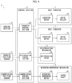
- Fig. 4 is a block diagram illustrating a configuration of the control system.
- the transfer device 3 includes a control section 8.
- the control section 8 controls, in the transfer device 3, operations of the reciprocating mechanism 4, the widening-narrowing mechanism 6, and the belt conveyors 7.
- the control section 8 includes a reciprocation control section 81, a sandwiching control section 82, and a transfer control section 83 in order to realize the control function.
- the transfer device 3 further includes, as elements constituting the control system, a transfer position sensor 11, a sandwiching position sensor 12, a reciprocation motor 44, a widening-narrowing motor 69, and a conveyor motor 75.
- the sensing section 13 senses a posture of the transfer target 200 while control of an operation of the transfer device 3 to transfer the transfer target 200 is carried out by the control section 8. A specific method of sensing a posture by the sensing section 13 will be described in Embodiments 1 through 4 later.
- the conveyor motor 75 is a motor included in the belt conveyor 7 and rotates to drive the drive roller 73.
- the reciprocation motor 44 is a motor included in the reciprocating mechanism 4 and drives a driven portion of the reciprocating mechanism 4.
- the widening-narrowing motor 69 is a motor included in the widening-narrowing mechanism 6, and rotates to drive the screw shaft 61.
- the widening-narrowing motor 69 drives the pair of screw shafts 61 simultaneously. Therefore, the widening-narrowing mechanism 6 includes a driving force transmission mechanism (not illustrated) for transmitting a driving force of the widening-narrowing motor 69 to the pair of screw shafts 61.
- the sandwiching control section 82 controls, in accordance with a position (detected conveyor position) of the belt conveyors 7 detected by the sandwiching position sensor 12 and a detected reciprocation position, rotation and stop of rotation of the widening-narrowing motor 69 when the transfer device 3 carries out a drawing operation. Specifically, the sandwiching control section 82 does not cause the widening-narrowing motor 69 to rotate until the detected reciprocation position changes from the retraction position to the intermediate position. When the intermediate position has been detected, the sandwiching control section 82 causes the widening-narrowing motor 69 to rotate in a direction in which the space between the pair of belt conveyors 7 is narrowed.
- the sandwiching control section 82 stops rotation of the widening-narrowing motor 69 when the sandwiching position has been detected. Moreover, the sandwiching control section 82 causes the widening-narrowing motor 69 to rotate until the detected reciprocation position changes from the projection position to the retraction position. When the retraction position has been detected, the sandwiching control section 82 causes the widening-narrowing motor 69 to rotate in a direction in which the space between the pair of belt conveyors 7 is widened.
- the prescribed posture is a posture of the transfer target 200 in a state in which a center line of the transfer target 200 conforms to the transfer direction (Y1 direction and Y2 direction).
- the prescribed posture includes also a posture of the transfer target 200 in a state in which the center line of the transfer target 200 is inclined within a predetermined minute angle range with respect to the transfer direction.
- the transfer device 3 is mounted on the carrier 1. Note, however, that the transfer device 3 can also be applied to a device such as a stacker crane.
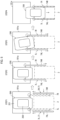
- FIG. 5 is a diagram illustrating an operation to transfer a transfer target 200 by a transfer device 3 in accordance with Embodiments 1 through 3 of the present invention.
- a constituent element having a function equivalent to that of a constituent element discussed above is given the same reference sign, and a description thereof is omitted. The same applies to embodiments described later.
- the belt conveyors 7L and 7R are at the sandwiching release position, as indicated by the solid lines in Fig. 5 .
- the transfer target 200 is deviated slightly to the left from the center in the accommodation section 101a.
- the slide board 41 described above moves (projects) to the accommodation section 101a side.
- the belt conveyors 7L and 7R are not yet operating.
- the slide board 41 reaches the intermediate position, as indicated by the two-dot chain lines in Fig. 5 , the belt conveyors 7L and 7R move, by the sandwiching mechanism 5 described above, in directions in which the space therebetween is narrowed, and belts 74L and 74R of the respective belt conveyors 7L and 7R move in the arrow directions at the same speed.
- a force of the belt conveyor 7L acts only on the left side surface of the transfer target 200, and therefore the posture of the transfer target 200 is tilted.
- the belt conveyor 7R comes into contact with the transfer target 200.
- the transfer control section 83 determines that a sensed posture sensed by the sensing section 13 is tilted with respect to the prescribed posture. Then, the transfer control section 83 either lowers a rotation speed of a conveyor motor 75 that drives the belt conveyor 7L or stops the rotation of the conveyor motor 75 while increasing a rotation speed of a conveyor motor 75 that drives the belt conveyor 7R.
- a conveyance speed (operation speed) of the belt conveyor 7R becomes higher than a conveyance speed of the belt conveyor 7L.
- the operations of the belts 74L and 74R of the pair of belt conveyors 7L and 7R are made different, and thus a difference between distances at which portions of the transfer target 200 that are held by the pair of belts 74L and 74R are moved can be reduced.
- the transfer target 200 is tilted, the posture thereof is corrected. Therefore, the transfer of the transfer target 200 can be smoothly carried out.
- Embodiment 2 of the present invention will discuss Embodiment 2 of the present invention with reference to Fig. 5 . In the present embodiment, only operations different from those described in Embodiment 1 will be described.
- the sensing section 13 senses the posture of the transfer target 200 based on a difference between loads applied to the pair of belt conveyors 7L and 7R.
- the transfer control section 83 carries out control so that, among the belts 74L and 74R of the respective belt conveyors 7L and 7R, an operation speed of one of the belts to which a relatively lighter load is applied becomes higher than an operation speed of the other belt to which a heavier load is applied.
- the loads on the belts 74L and 74R are detected based on measured values of electric currents flowing through the conveyor motors 75 that drive the belts 74L and 74R, respectively. The control carried out in this case will be described below.
- the belt conveyor 7L is in contact with the transfer target 200, and therefore a load is applied to the belt 74L.
- the load is light, and therefore a difference between loads applied to the belts 74L and 74R is smaller than a predetermined value D1. Therefore, in this state, the sensing section 13 does not sense that the posture of the transfer target 200 is tilted.
- the transfer control section 83 continues the control until the difference between loads on the pair of belts 74L and 74R becomes the predetermined value D1 or less.
- Embodiment 3 of the present invention will discuss Embodiment 3 of the present invention with reference to Fig. 5 . In the present embodiment, only operations different from those described in Embodiments 1 and 2 will be described.
- the transfer control section 83 continues the control until the posture of the transfer target 200 sensed by the sensing section 13 becomes the prescribed posture. Specifically, the transfer control section 83 compares a captured image of the transfer target 200 with an image of the transfer target 200 in the prescribed posture, and thereby determines whether or not the posture of the transfer target 200 has become the prescribed posture. Thus, the posture of the transfer target 200 can be accurately corrected to the prescribed posture.
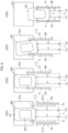
- Fig. 6 is a diagram illustrating an operation to transfer a transfer target 200 by a transfer device 3 in accordance with Embodiment 4 of the present invention. In the present embodiment, only operations different from those described in Embodiments 1 through 3 will be described.
- the sensing section 13 includes two distance sensors 11L and 11R.
- the distance sensors 11L and 11R are, for example, disposed at two different measurement positions that are apart from each other in a right-and-left direction at an end portion on the base 2 of the transfer device 3, the end portion being farthest from the accommodation section 101a.
- the distance sensors 11L and 11R may be disposed at an end portion of the base 2 at a side opposite to the above positions, in order to measure a distance between the accommodation section 101a illustrated in Fig. 6 and the transfer target 200 that is disposed at an accommodation section 101a (not illustrated) at an opposite side of the base 2 from the accommodation section 101a illustrated in Fig. 6 .
- the sensing section 13 senses the posture of the transfer target 200 based on a difference between straight-line distances in the transfer direction from the transfer target 200 which have been respectively measured by the distance sensors 11L and 11R.
- the transfer control section 83 carries out control so that, a conveyance speed of one of the pair of belts 74L and 74R at which a relatively longer straight-line distance has been measured becomes higher than a conveyance speed of the other belt.
- the control carried out in this case will be described below.
- the transfer control section 83 continues the control until the difference between the straight-line distances L1 and L2 becomes a predetermined value D2 or less.
- the transfer control section 83 continues the control of the conveyance speed until the difference between the straight-line distances L1 and L2 becomes the predetermined value D2 or less.
- the posture of the transfer target 200 can be more accurately corrected.
- control blocks can be realized by a logic circuit.
- the present invention encompasses, in its scope, an integrated circuit in which a logic circuit that functions as each of the control blocks is formed.
- the functions of the control blocks can be realized, for example, by a quantum computer.
- the sensing section senses the posture based on a difference between loads respectively applied to the pair of support bodies; and the control section carries out control so that an operation speed of one of the pair of support bodies to which a relatively lighter load is applied becomes higher than an operation speed of the other support body to which a heavier load is applied.
- control section continues the control until the difference between loads on the pair of support bodies becomes a predetermined value or less.
- the posture of the transfer target in a case where it can be considered that the posture of the transfer target has been corrected to the prescribed posture if the difference between the loads is the predetermined value or less, it is possible to correct the posture of the transfer target more accurately by continuing the control of the operation speeds until the difference between the loads becomes the predetermined value or less.
- the sensing section senses the posture based on a difference between straight-line distances from the transfer target in a transfer direction, the straight-line distances being respectively measured at two different measurement positions that are apart from each other in a right-and-left direction in the transfer device; and the control section carries out control so that an operation speed of one of the pair of support bodies at a measurement position side where a relatively longer straight-line distance has been measured becomes higher than an operation speed of the other support body.
- a portion of the transfer target held by one of the pair of support bodies at a measurement position side where a relatively longer straight-line distance has been measured is caused to move more than a portion of the transfer target held by the other support body.
- the posture of the transfer target is corrected.
- control section continues the control until the difference between straight-line distances becomes a predetermined value or less.
- the posture of the transfer target in a case where it can be considered that the posture of the transfer target has been corrected to the prescribed posture if the difference between the straight-line distances is the predetermined value or less, it is possible to correct the posture of the transfer target more accurately by continuing the control of the operation speeds until the difference between the straight-line distances becomes the predetermined value or less.
- the sensing section senses the posture based on a captured image of the transfer target; and the control section carries out control so that an operation speed of one of the pair of support bodies at which the transfer target is tilted becomes lower than an operation speed of the other support body.
- a portion of the transfer target held by one of the pair of support bodies at which the transfer target is tilted is moved less than a portion of the transfer target held by the other support body.
- the posture of the transfer target is corrected.
- the pair of support bodies are belts of belt conveyors.
- the configuration it is possible to secure large contact areas in which the belts of the belt conveyors are in contact with the transfer target. Therefore, the configuration is suitable for transferring the transfer target.
- the present invention is not limited to the embodiments above, but can be altered by a skilled person in the art within the scope of the claims.
- the present invention also encompasses, in its technical scope, any embodiment derived by appropriately combining technical means disclosed in differing embodiments.
Landscapes
- Engineering & Computer Science (AREA)
- Mechanical Engineering (AREA)
- Control Of Conveyors (AREA)
- Attitude Control For Articles On Conveyors (AREA)
- Warehouses Or Storage Devices (AREA)
- Specific Conveyance Elements (AREA)
- Intermediate Stations On Conveyors (AREA)
Applications Claiming Priority (2)
| Application Number | Priority Date | Filing Date | Title |
|---|---|---|---|
| JP2021144986A JP7517287B2 (ja) | 2021-09-06 | 2021-09-06 | 移載装置および搬送車 |
| PCT/JP2022/023563 WO2023032404A1 (ja) | 2021-09-06 | 2022-06-13 | 移載装置および搬送車 |
Publications (2)
| Publication Number | Publication Date |
|---|---|
| EP4400451A1 true EP4400451A1 (de) | 2024-07-17 |
| EP4400451A4 EP4400451A4 (de) | 2025-08-06 |
Family
ID=85411147
Family Applications (1)
| Application Number | Title | Priority Date | Filing Date |
|---|---|---|---|
| EP22863992.8A Pending EP4400451A4 (de) | 2021-09-06 | 2022-06-13 | Übertragungsvorrichtung und transportfahrzeug |
Country Status (9)
| Country | Link |
|---|---|
| US (1) | US20240425276A1 (de) |
| EP (1) | EP4400451A4 (de) |
| JP (1) | JP7517287B2 (de) |
| KR (1) | KR20240058134A (de) |
| CN (1) | CN117957179A (de) |
| AU (1) | AU2022336714A1 (de) |
| CA (1) | CA3230868A1 (de) |
| TW (1) | TW202325630A (de) |
| WO (1) | WO2023032404A1 (de) |
Families Citing this family (1)
| Publication number | Priority date | Publication date | Assignee | Title |
|---|---|---|---|---|
| CN117446399B (zh) * | 2023-12-11 | 2025-12-19 | 杭州德创能源设备有限公司 | 一种货物堆垛平移转运装置 |
Family Cites Families (10)
| Publication number | Priority date | Publication date | Assignee | Title |
|---|---|---|---|---|
| JP2002114317A (ja) | 2000-10-05 | 2002-04-16 | Kito Corp | 移載装置 |
| JP4396494B2 (ja) * | 2004-11-30 | 2010-01-13 | 株式会社豊田自動織機 | 物品移載装置及び物品移載方法 |
| JP4855865B2 (ja) * | 2006-08-17 | 2012-01-18 | 株式会社岡村製作所 | 荷移載装置及び荷移載方法 |
| JP4941713B2 (ja) * | 2006-09-05 | 2012-05-30 | 株式会社ダイフク | 物品搬送装置 |
| JP5045186B2 (ja) * | 2007-03-29 | 2012-10-10 | 株式会社Ihi | スタッカクレーン及び自動倉庫 |
| JP2010208816A (ja) * | 2009-03-11 | 2010-09-24 | Murata Machinery Ltd | 移載装置 |
| JP2013047150A (ja) * | 2012-12-04 | 2013-03-07 | Ihi Corp | 物品移載装置 |
| US10173838B2 (en) * | 2014-12-10 | 2019-01-08 | Swisslog Evomatic Gmbh | Load-receiving device |
| JP6687654B2 (ja) * | 2018-03-14 | 2020-04-28 | ファナック株式会社 | 協働ロボットの制御装置及び制御方法 |
| JP7476819B2 (ja) * | 2021-02-16 | 2024-05-01 | トヨタ自動車株式会社 | 搬送システム及び搬送方法 |
-
2021
- 2021-09-06 JP JP2021144986A patent/JP7517287B2/ja active Active
-
2022
- 2022-06-13 CN CN202280060060.5A patent/CN117957179A/zh active Pending
- 2022-06-13 CA CA3230868A patent/CA3230868A1/en active Pending
- 2022-06-13 AU AU2022336714A patent/AU2022336714A1/en active Pending
- 2022-06-13 US US18/689,129 patent/US20240425276A1/en active Pending
- 2022-06-13 WO PCT/JP2022/023563 patent/WO2023032404A1/ja not_active Ceased
- 2022-06-13 KR KR1020247010750A patent/KR20240058134A/ko active Pending
- 2022-06-13 EP EP22863992.8A patent/EP4400451A4/de active Pending
- 2022-07-05 TW TW111125097A patent/TW202325630A/zh unknown
Also Published As
| Publication number | Publication date |
|---|---|
| TW202325630A (zh) | 2023-07-01 |
| WO2023032404A1 (ja) | 2023-03-09 |
| JP7517287B2 (ja) | 2024-07-17 |
| AU2022336714A1 (en) | 2024-03-28 |
| CA3230868A1 (en) | 2023-03-09 |
| JP2023038078A (ja) | 2023-03-16 |
| US20240425276A1 (en) | 2024-12-26 |
| KR20240058134A (ko) | 2024-05-03 |
| CN117957179A (zh) | 2024-04-30 |
| EP4400451A4 (de) | 2025-08-06 |
Similar Documents
| Publication | Publication Date | Title |
|---|---|---|
| KR101453230B1 (ko) | 롤체 반송장치 | |
| US5525025A (en) | Loading/unloading apparatus on a vehicle and method therefor | |
| US20220274658A1 (en) | Vehicle configurator | |
| CN110562764B (zh) | 码放装置、装车机及装车系统 | |
| US20180327186A1 (en) | Conveying system | |
| EP4400451A1 (de) | Übertragungsvorrichtung und transportfahrzeug | |
| CN110199470B (zh) | 物品移载装置 | |
| TW201350421A (zh) | 移載裝置及移載裝置之控制方法 | |
| CN106029533A (zh) | 用于转运装货单元的装置和方法 | |
| KR101448086B1 (ko) | 반송 시스템 | |
| RU2852729C2 (ru) | Перемещающее устройство и транспортное средство | |
| JP3485153B2 (ja) | 物品移載装置 | |
| JP3807147B2 (ja) | 搬送設備 | |
| KR102246806B1 (ko) | 캐리어 이송 장치 | |
| JP6536218B2 (ja) | 昇降搬送装置 | |
| JP2000211705A (ja) | 物品移載装置 | |
| JP3388122B2 (ja) | 物品搬送設備 | |
| KR940004488B1 (ko) | 로워 드럼 공급 장치 | |
| JP7002173B2 (ja) | 移載装置 | |
| JP2002037057A (ja) | 無人搬送車、その本体支持ストッパおよび無人搬送システム | |
| JP2004137022A (ja) | 荷の移載装置 | |
| JP2546441Y2 (ja) | 搬送車上のコンベヤのフローティング装置 | |
| JP3306318B2 (ja) | 搬出コンベア装置 | |
| JPS6144772B2 (de) | ||
| JP2004142850A (ja) | 移載装置 |
Legal Events
| Date | Code | Title | Description |
|---|---|---|---|
| STAA | Information on the status of an ep patent application or granted ep patent |
Free format text: STATUS: THE INTERNATIONAL PUBLICATION HAS BEEN MADE |
|
| PUAI | Public reference made under article 153(3) epc to a published international application that has entered the european phase |
Free format text: ORIGINAL CODE: 0009012 |
|
| STAA | Information on the status of an ep patent application or granted ep patent |
Free format text: STATUS: REQUEST FOR EXAMINATION WAS MADE |
|
| 17P | Request for examination filed |
Effective date: 20240311 |
|
| AK | Designated contracting states |
Kind code of ref document: A1 Designated state(s): AL AT BE BG CH CY CZ DE DK EE ES FI FR GB GR HR HU IE IS IT LI LT LU LV MC MK MT NL NO PL PT RO RS SE SI SK SM TR |
|
| DAV | Request for validation of the european patent (deleted) | ||
| DAX | Request for extension of the european patent (deleted) | ||
| A4 | Supplementary search report drawn up and despatched |
Effective date: 20250703 |
|
| RIC1 | Information provided on ipc code assigned before grant |
Ipc: B65G 1/04 20060101AFI20250627BHEP |