EP4390551A1 - Bilderzeugungsrolle, aufladerolle, verfahren zur inspektion der bilderzeugungsrolle und verfahren zur inspektion der aufladerolle - Google Patents
Bilderzeugungsrolle, aufladerolle, verfahren zur inspektion der bilderzeugungsrolle und verfahren zur inspektion der aufladerolle Download PDFInfo
- Publication number
- EP4390551A1 EP4390551A1 EP22858151.8A EP22858151A EP4390551A1 EP 4390551 A1 EP4390551 A1 EP 4390551A1 EP 22858151 A EP22858151 A EP 22858151A EP 4390551 A1 EP4390551 A1 EP 4390551A1
- Authority
- EP
- European Patent Office
- Prior art keywords
- surface layer
- roller
- contact angle
- charge roller
- image
- Prior art date
- Legal status (The legal status is an assumption and is not a legal conclusion. Google has not performed a legal analysis and makes no representation as to the accuracy of the status listed.)
- Pending
Links
Images

Classifications
-
- G—PHYSICS
- G03—PHOTOGRAPHY; CINEMATOGRAPHY; ANALOGOUS TECHNIQUES USING WAVES OTHER THAN OPTICAL WAVES; ELECTROGRAPHY; HOLOGRAPHY
- G03G—ELECTROGRAPHY; ELECTROPHOTOGRAPHY; MAGNETOGRAPHY
- G03G15/00—Apparatus for electrographic processes using a charge pattern
- G03G15/02—Apparatus for electrographic processes using a charge pattern for laying down a uniform charge, e.g. for sensitising; Corona discharge devices
- G03G15/0208—Apparatus for electrographic processes using a charge pattern for laying down a uniform charge, e.g. for sensitising; Corona discharge devices by contact, friction or induction, e.g. liquid charging apparatus
- G03G15/0216—Apparatus for electrographic processes using a charge pattern for laying down a uniform charge, e.g. for sensitising; Corona discharge devices by contact, friction or induction, e.g. liquid charging apparatus by bringing a charging member into contact with the member to be charged, e.g. roller, brush chargers
- G03G15/0233—Structure, details of the charging member, e.g. chemical composition, surface properties
-
- F—MECHANICAL ENGINEERING; LIGHTING; HEATING; WEAPONS; BLASTING
- F16—ENGINEERING ELEMENTS AND UNITS; GENERAL MEASURES FOR PRODUCING AND MAINTAINING EFFECTIVE FUNCTIONING OF MACHINES OR INSTALLATIONS; THERMAL INSULATION IN GENERAL
- F16C—SHAFTS; FLEXIBLE SHAFTS; ELEMENTS OR CRANKSHAFT MECHANISMS; ROTARY BODIES OTHER THAN GEARING ELEMENTS; BEARINGS
- F16C13/00—Rolls, drums, discs, or the like; Bearings or mountings therefor
- F16C13/006—Guiding rollers, wheels or the like, formed by or on the outer element of a single bearing or bearing unit, e.g. two adjacent bearings, whose ratio of length to diameter is generally less than one
-
- G—PHYSICS
- G03—PHOTOGRAPHY; CINEMATOGRAPHY; ANALOGOUS TECHNIQUES USING WAVES OTHER THAN OPTICAL WAVES; ELECTROGRAPHY; HOLOGRAPHY
- G03G—ELECTROGRAPHY; ELECTROPHOTOGRAPHY; MAGNETOGRAPHY
- G03G15/00—Apparatus for electrographic processes using a charge pattern
- G03G15/06—Apparatus for electrographic processes using a charge pattern for developing
- G03G15/08—Apparatus for electrographic processes using a charge pattern for developing using a solid developer, e.g. powder developer
- G03G15/0806—Apparatus for electrographic processes using a charge pattern for developing using a solid developer, e.g. powder developer on a donor element, e.g. belt, roller
- G03G15/0818—Apparatus for electrographic processes using a charge pattern for developing using a solid developer, e.g. powder developer on a donor element, e.g. belt, roller characterised by the structure of the donor member, e.g. surface properties
-
- F—MECHANICAL ENGINEERING; LIGHTING; HEATING; WEAPONS; BLASTING
- F16—ENGINEERING ELEMENTS AND UNITS; GENERAL MEASURES FOR PRODUCING AND MAINTAINING EFFECTIVE FUNCTIONING OF MACHINES OR INSTALLATIONS; THERMAL INSULATION IN GENERAL
- F16C—SHAFTS; FLEXIBLE SHAFTS; ELEMENTS OR CRANKSHAFT MECHANISMS; ROTARY BODIES OTHER THAN GEARING ELEMENTS; BEARINGS
- F16C2208/00—Plastics; Synthetic resins, e.g. rubbers
-
- F—MECHANICAL ENGINEERING; LIGHTING; HEATING; WEAPONS; BLASTING
- F16—ENGINEERING ELEMENTS AND UNITS; GENERAL MEASURES FOR PRODUCING AND MAINTAINING EFFECTIVE FUNCTIONING OF MACHINES OR INSTALLATIONS; THERMAL INSULATION IN GENERAL
- F16C—SHAFTS; FLEXIBLE SHAFTS; ELEMENTS OR CRANKSHAFT MECHANISMS; ROTARY BODIES OTHER THAN GEARING ELEMENTS; BEARINGS
- F16C2324/00—Apparatus used in printing
- F16C2324/16—Printing machines
Definitions
- This invention relates to an image-forming roll used for electrophotographic image formation, for example, to a charge roller.
- Patent Document 1 discloses a configuration in which a surface roughness of a conductive roller such as the electrically charged roller is optimized.
- Patent Document 2 discloses a configuration in which a surface layer of a conductive roller is formed from two types of particles that have different diameters.
- an electrophotographic image-forming apparatus is configured to have a cleaning blade that removes toner adhering to a surface of a roller member such as an electrically charged roller.
- a cleaning blade that removes toner adhering to a surface of a roller member such as an electrically charged roller.
- toner components that cannot be completely removed by the cleaning blade may remain as a thin film (toner filming) over a wide area of the surface of the roller member.
- an object of one aspect of this invention is to reduce adhesion of toner components to a surface of an image-forming roller.
- An image-forming roller comprises a roller core and a surface layer formed on an outer peripheral surface of the roller core, and a contact angle between the surface layer and toluene is 6° or more, and a contact angle between the surface layer and tetradecane is 22° or more.
- the contact angle between the surface layer and toluene is 13° or more, and the contact angle between the surface layer and tetradecane is 25° or more.
- the surface layer contains a material that includes a silicon-based urethane resin.
- a charge roller according to another embodiment of the present invention is used for an electrophotographic apparatus and comprises a body and a surface layer formed on an outer peripheral surface of the body, and a contact angle between the surface layer and toluene is 6° or more, and a contact angle between the surface layer and tetradecane is 22° or more.
- the contact angle between the surface layer and toluene is 13° or more, and the contact angle between the surface layer and tetradecane is 25° or more.
- a method for inspecting an image-forming roller according to one embodiment of the invention that includes a body and a surface layer formed on an outer circumferential surface of the body, to determine whether the image-forming roller is in good condition or not in good condition, the method comprising determining that the image-forming roller is in good condition when a contact angle between the surface layer and toluene is 6° or more, and when a contact angle between the surface layer and tetradecane is 22° or more.
- the image-forming roller is determined to be in good condition when the contact angle between the surface layer and toluene is 13° or more, and when the contact angle between the surface layer and tetradecane is 25° or more.
- a method for inspecting a charge roller according to another embodiment of the present invention that includes a base and a surface layer formed on an outer circumferential surface of the base, to determine whether the charge roller is in good condition or not in good condition, the method comprising determining that the charge roller is in good condition when a contact angle between the surface layer and toluene is 6° or more, and when a contact angle between the surface layer and tetradecane is 22° or more.
- the charge roller is determined to be in good condition when the contact angle between the surface layer and toluene is 13° or more, and when the contact angle between the surface layer and tetradecane is 25° or more.
- adhesion of toner components to the surface of the image-forming roller can be reduced.
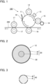
- FIG. 1 is a diagram showing an image-forming apparatus 100 according to one configuration of the present invention.
- the image-forming apparatus is an electrophotographic printing apparatus (for example, a multifunction printer) that forms images on a sheet-like recording medium 200 such as printing paper.
- the image-forming apparatus 100 includes a photoconductor drum 11, a charge roller 12, an exposure device 13, a supply roller 14, a developing roller 15, a transfer roller 16, a pair of fusing rollers 17, and a cleaning blade 18.
- the charge roller 12, the supply roller 14, the developing roller 15, the transfer roller 16, and the fusing rollers 17 are cylindrical roller members (image-forming rollers) used for forming electrophotographic images.
- the charge roller 12 is a conductive roller that uniformly charges the surface of the photoconductor drum 11.
- the exposure device 13 forms an electrostatic latent image on the photoconductor drum 11 by exposing light to the surface of the drum.
- the supply roller 14 supplies charged toner to the surface of the developing roller 15.
- the developing roller 15 attaches the toner to the electrostatic latent image on the surface of the photoconductor drum 11.
- the transfer roller 16 transfers the toner attached to the surface of the photoconductor drum 11 to the recording medium 200.
- the pair of fusing rollers 17 fixes the transferred toner to the surface of the recording medium 200.
- the cleaning blade 18 removes toner remaining on the surface of the photoconductor drum 11.
- FIG. 2 is a cross-sectional view of the charge roller.
- the charge roller 12 is a cylindrical roller member that has a roller core 20 and a surface layer 30.
- the roller core 20 has a core member 21 and an elastic member 22.
- the core member 21 is a cylindrical member and constitutes a rotation of axis of the charge roller 12.
- the core member 21 is formed from a metal material such as a SUS alloy or a resin material such as polyimide, for example.
- the elastic member 22 is a cylindrical portion that is formed on an outer peripheral surface of the core member 21.
- the elastic member 22 is formed from a conductive elastic material.
- materials for the elastic member 22 include various rubber materials such as polyurethane rubber (PUR), epichlorohydrin rubber (ECO), nitrile rubber (NBR), styrene rubber (SBR), chloroprene rubber (CR), etc.
- PUR polyurethane rubber
- ECO epichlorohydrin rubber
- NBR nitrile rubber
- SBR styrene rubber
- CR chloroprene rubber
- Another layer such as an adhesion layer that improves adhesion between the outer peripheral surface of the core member 21 and the inner peripheral surface of the elastic member 22 may be formed between the outer peripheral surface of the core member 21 and the inner peripheral surface of the elastic member 22.
- the surface layer 30 is a membrane formed on the outer peripheral surface of the roller core 20. Specifically, the surface layer 30 is formed over the entire area of the outer peripheral surface of the elastic member 22 with a substantially uniform thickness. The thickness of the surface layer 30 may be freely selected, and is, for example, equal to or greater than 2 ⁇ m and equal to or smaller than 40 ⁇ m.
- the outer peripheral surface of the surface layer 30 comprises the surface of the charge roller 12. As described below, the surface layer 30 includes a base material that includes a silicon-based urethane resin.
- the roller core 20 of the charge roller 12 is prepared.
- the elastic member 22 of the roller core 20 is formed, for example, of vulcanized epichlorohydrin rubber (ECO) with a hardness of 50° to 64°.
- the surface roughness of the outer peripheral surface of the elastic member 22 (maximum height Rz conformed to JIS 82) is 3 ⁇ m.
- Mechanical polishing is performed on the roller core 20.
- the mechanical polishing includes dry polishing and wet polishing. Dry polishing is mechanical polishing using grindstones; while wet polishing is mechanical polishing using waterproof sandpapers. The wet polishing may be omitted.
- the surface layer 30 is formed on the outer peripheral surface of the roller core 20. More specifically, a coating liquid of a predetermined composition is agitated by utilizing, for example, ultrasonic waves, and is coated on the outer peripheral surface of the roller core 20.
- the coating method used for the coating liquid may be freely selected. For example, a spray coating method is appropriate.
- the surface layer 30 is then fired by utilizing, for example, an electric furnace.
- the electric furnace is set to a temperature of 80°C or higher and 160°C or lower, for example.
- the firing time is set to an appropriate time of not less than 20 minutes and not more than 60 minutes.
- toner components In a configuration where the surface layer 30 of the charge roller 12 and the components contained in the toner (hereinafter referred to as "toner components") have a high affinity, residual toner components remaining on the surface of the photoconductor drum 11 after use of the cleaning blade 18 are likely to remain as a thin film over a wide area of the surface of the charge roller 12.
- residual toner components remain on the surface of the charge roller 12 (toner filming)
- errors can occur in design values for a size of a nip at which the photoconductor drum 11 and the charge roller 12 are in contact with each other, or in a clearance between the photoconductor drum 11 and the charge roller 12 around the nip.
- FIG. 3 is a cross-sectional view of a toner particle 40 of this embodiment.
- the toner particle 40 includes a spherical toner core 41 and a shell layer 42 formed on the surface of the toner core 41.
- the shell layer 42 entirely or partially covers the surface of the toner core 41.
- the toner core 41 contains additives such as wax, for example, in addition to color materials such as pigments.
- the wax is composed of a material containing aliphatic hydrocarbons as a major component, for example.
- the shell layer 42 is composed of a material containing styrene-acrylic resin as a major component, for example.
- the inventors of the present invention envisaged aliphatic hydrocarbons and styrene-acrylic resin as toner components that could adhere to the surface layer 30 of the charge roller 12.
- the aliphatic hydrocarbons contained in the wax of the toner core 41 are characterized by their large hydrocarbon content.
- the styrene-acrylic resin contained in the shell layer 42 is classified as an aromatic hydrocarbon.
- the inventors took into consideration the characteristics of the wax with a large hydrocarbon content and the characteristics of the shell layer 42, which is the aromatic hydrocarbon, and selected from among several resin materials a silicon-based urethane resin for use as a base material of the surface layer 30 of the charge roller 12.
- a carbonate urethane resin was also considered as a candidate material for the surface layer 30 of the charge roller 12.
- the carbonate urethane resin has a large hydrocarbon content similarly to the wax, and is classified as an aromatic hydrocarbon similarly to the shell layer 42. Therefore, it was assumed that the carbonate urethane resin would have a high affinity with the toner components.
- the silicon-based urethane resin has a small hydrocarbon content and contains no aromatic hydrocarbon. Therefore, with a view to reducing the wettability of the toner components, the silicon-based urethane resin was deemed appropriate for use as a material of the surface layer 30 of the charge roller 12.
- Tetradecane which has a large hydrocarbon content similarly to the wax (aliphatic hydrocarbon), was envisaged as a solvent for the wax.
- Toluene which is classified as an aromatic hydrocarbon similarly to the shell layer 42 (styrene-acrylic resin), was envisaged as the solvent for the shell layer 42. Accordingly, when envisaging tetradecane and toluene as the toner solvents, consideration was given to the wettability (contact angle) between the toner solvents and the surface layer 30 of the charge roller 12.
- Table 1 below is a chart showing results of evaluating the contact angle between the surface layer 30 and tetradecane, the contact angle between the surface layer 30 and toluene, and the presence of toner filming for each of several samples (Example 1, Example 2, and Comparative example) with different conditions for the surface layer 30 of the charge roller 12.
- EXAMPLE 1 EXAMPLE 2 COMPARATIVE EXAMPLE SURFACE LAYER 30 BASE MATERIAL SILICON-BASED URETHANE RESIN SILICON-BASED URETHANE RESIN CARBONATE URETHANE RESIN CONTACT ANGLE [°] TOLUENE [SHELL LAYER] 13 6 2 TETRADECANE [WAX] 25 22 17 TONER FILMING NO NO YES
- the contact angle (°) in Table 1 is an index of the wettability of the solvent to the surface layer 30 of the charge roller 12.
- each contact angle in Table 1 was measured by a contact angle droplet method to analyze a shape of a droplet of solvent dripped onto the surface of the surface layer 30.
- the contact angle was calculated by observing the droplet when 10 seconds had elapsed from dripping 0.1- ⁇ L of solvent onto the surface of the surface layer 30.
- Table 1 also includes the results of evaluation of occurrence of a thin-film-like solvent (toner filming) on the surface of the charge roller 12. Specifically, a visual check for occurrence of toner filming on the surface of the charge roller 12 was carried out after printing the same image on a total of 10,000 sheets of printing paper using the image-forming apparatus 100.
- Example 1 and Example 2 comprise samples in which the surface layer 30 of the charge roller 12 was formed from a base material containing a silicone urethane resin.
- the comparative example comprises a sample in which the surface layer 30 of the charge roller 12 is formed from a base material containing a carbonate urethane resin.
- Table 2 is a chart showing the composition of the coating liquid used for forming the surface layer 30. As will be understood from Table 2, the composition in Example 1 and the composition in Example 2 differ from each other.
- the contact angle between the surface layer 30 and toluene is 2°, and the contact angle between the surface layer 30 and tetradecane is 17°.
- the base material of the surface layer 30 of the charge roller 12 contains carbonate urethane resin. Due to the small contact angle (high wettability) as described above, occurrence of toner filming was observed.
- Example 1 the contact angle between the surface layer 30 and toluene is 13° and the contact angle between the surface layer 30 and tetradecane is 25°.
- the base material of the surface layer 30 of the charge roller 12 contains silicon-based urethane resin.
- occurrence of toner filming was not observed.
- Example 2 in which the base material of the surface layer 30 contains silicon-based urethane resin, the contact angle of the surface layer 30 and toluene is 6° and the contact angle to tetradecane is 22°. In Example 2, occurrence of toner filming was also not observed.
- Example 2 a configuration (Example 2) in which the contact angle of the surface of the charge roller 12 and toluene is 6° or more and the contact angle of the surface of the charge roller 12 and tetradecane is 22° or more is appropriate. Even more appropriate is a configuration (Example 1) in which the contact angle of the surface of the charge roller 12 and toluene is 13° or more and the contact angle of the surface of the charge roller 12 and tetradecane is 25° or more.
- an affinity of the toner components to the surface layer 30 of the charge roller 12 is reduced, thereby resulting in prevention of occurrence of toner filming on the surface layer 30.
- errors in the size of the nip at which the photoconductor drum 11 and the charge roller 12 are in contact with each other, or in the clearance between the photoconductor drum 11 and the charge roller 12 around the nip are reduced. Therefore, a decrease in discharge efficiency from the charge roller 12 to the photoconductor drum 11 is reduced, and as a result, high-quality images are formed by the image-forming apparatus 100.
- FIG. 4 is a flow chart showing an inspection process for determining whether the charge roller 12 is in good condition or is not in good condition.
- the inspection process shown in FIG. 4 is performed after manufacture of the charge roller 12 using the method of manufacture described above.
- the method of manufacture of the charge roller 12 may include the inspection process shown in FIG. 4 .
- the charge roller 12 to be inspected is prepared (process S1). After process S1 is carried out, in process S2 it is determined whether both a first condition and a second condition are satisfied.
- the first condition is that the contact angle between the surface layer 30 of the charge roller 12 and toluene is 6° or more
- the second condition is that the contact angle between the surface layer 30 of the charge roller 12 and tetradecane is 22° or more.
- the charge roller 12 is in good condition when the contact angle between the surface layer 30 thereof and toluene is 6° or more and when the contact angle between the surface layer 30 thereof and tetradecane is 22° or more.
- toner filming on the surface layer 30 of the charge roller 12 is prevented when the above conditions are satisfied. Therefore, it is possible to provide a charge roller 12 that can maintain the quality of images formed by the image-forming apparatus 100 at a high level.
- the charge roller 12 is in good condition when the contact angle between the surface layer 30 of the charge roller 12 and toluene is 13° or more and the contact angle between the surface layer 30 of the charge roller 12 and tetradecane is 25° or more.
- the same inspection process may be applied to any image-forming roller other than the charge roller 12.
- the image-forming roller is determined to be in good condition.
- the image-forming roller may be determined to be in good condition when the contact angle between the surface layer of an image-forming roller and toluene is 13° or more and when the contact angle between the surface layer of the image-forming roller and tetradecane is 25° or more.
Landscapes
- Physics & Mathematics (AREA)
- General Physics & Mathematics (AREA)
- Engineering & Computer Science (AREA)
- Plasma & Fusion (AREA)
- General Engineering & Computer Science (AREA)
- Mechanical Engineering (AREA)
- Rolls And Other Rotary Bodies (AREA)
- Electrostatic Charge, Transfer And Separation In Electrography (AREA)
Applications Claiming Priority (2)
| Application Number | Priority Date | Filing Date | Title |
|---|---|---|---|
| JP2021132842 | 2021-08-17 | ||
| PCT/JP2022/023970 WO2023021827A1 (ja) | 2021-08-17 | 2022-06-15 | 画像形成用ロール、帯電ロール、画像形成用ロールの検査方法、および帯電ロールの検査方法 |
Publications (2)
| Publication Number | Publication Date |
|---|---|
| EP4390551A1 true EP4390551A1 (de) | 2024-06-26 |
| EP4390551A4 EP4390551A4 (de) | 2025-11-26 |
Family
ID=85240487
Family Applications (1)
| Application Number | Title | Priority Date | Filing Date |
|---|---|---|---|
| EP22858151.8A Pending EP4390551A4 (de) | 2021-08-17 | 2022-06-15 | Bilderzeugungsrolle, aufladerolle, verfahren zur inspektion der bilderzeugungsrolle und verfahren zur inspektion der aufladerolle |
Country Status (5)
| Country | Link |
|---|---|
| US (1) | US12547092B2 (de) |
| EP (1) | EP4390551A4 (de) |
| JP (1) | JPWO2023021827A1 (de) |
| CN (1) | CN117813559A (de) |
| WO (1) | WO2023021827A1 (de) |
Family Cites Families (11)
| Publication number | Priority date | Publication date | Assignee | Title |
|---|---|---|---|---|
| JPH11167273A (ja) * | 1997-09-29 | 1999-06-22 | Tokai Rubber Ind Ltd | 低硬度導電性ロール |
| JP3617349B2 (ja) * | 1998-12-22 | 2005-02-02 | 東海ゴム工業株式会社 | 導電性ロール |
| JP2002169355A (ja) * | 2000-11-30 | 2002-06-14 | Canon Chemicals Inc | 帯電ロール及び電子写真装置 |
| JP2002296877A (ja) * | 2001-03-30 | 2002-10-09 | Mitsubishi Chemicals Corp | 感光体カートリッジ,画像形成装置および画像形成方法 |
| EP1621258B1 (de) * | 2003-04-15 | 2011-07-27 | Nippon Soda Co., Ltd. | Verfahren zur herstellung eines dünnen organischen films |
| JP2007232861A (ja) * | 2006-02-28 | 2007-09-13 | Canon Inc | 導電性ローラ |
| JP6216284B2 (ja) * | 2014-04-24 | 2017-10-18 | 住友理工株式会社 | 電子写真用部材 |
| JP2019191519A (ja) | 2018-04-27 | 2019-10-31 | Nok株式会社 | 導電性ロール |
| JP2019219498A (ja) | 2018-06-19 | 2019-12-26 | Nok株式会社 | 導電性ロール |
| US10353317B1 (en) * | 2018-07-24 | 2019-07-16 | Xerox Corporation | Electrostatic charging member |
| JP2020060749A (ja) * | 2018-10-12 | 2020-04-16 | 信越ポリマー株式会社 | 現像ローラ、現像装置及び画像形成装置 |
-
2022
- 2022-06-15 JP JP2023542238A patent/JPWO2023021827A1/ja active Pending
- 2022-06-15 EP EP22858151.8A patent/EP4390551A4/de active Pending
- 2022-06-15 WO PCT/JP2022/023970 patent/WO2023021827A1/ja not_active Ceased
- 2022-06-15 US US18/294,100 patent/US12547092B2/en active Active
- 2022-06-15 CN CN202280051705.9A patent/CN117813559A/zh active Pending
Also Published As
| Publication number | Publication date |
|---|---|
| US20240337963A1 (en) | 2024-10-10 |
| WO2023021827A1 (ja) | 2023-02-23 |
| US12547092B2 (en) | 2026-02-10 |
| CN117813559A (zh) | 2024-04-02 |
| JPWO2023021827A1 (de) | 2023-02-23 |
| EP4390551A4 (de) | 2025-11-26 |
Similar Documents
| Publication | Publication Date | Title |
|---|---|---|
| EP3605241B1 (de) | Elektrofotografisches element, elektrofotografische prozesskassette und elektrofotografische bilderzeugungsvorrichtung | |
| EP3605240B1 (de) | Elektrofotografisches element, elektrofotografische prozesskassette und elektrofotografische bilderzeugungsvorrichtung | |
| US7570905B2 (en) | Developing roller, developing apparatus using the same, and image forming apparatus | |
| JP2016164654A (ja) | 電子写真用部材、プロセスカートリッジおよび電子写真画像形成装置 | |
| JP2017156745A (ja) | 現像ローラ、プロセスカートリッジおよび電子写真画像形成装置 | |
| EP4220304A1 (de) | Reinigungsklinge für ein zwischenübertragungsmedium und bilderzeugungsvorrichtung | |
| US6594462B2 (en) | Developing apparatus using toner with conductive particles | |
| JP2022126823A (ja) | 帯電ロール | |
| JP6669394B2 (ja) | 現像剤担持体、プロセスカートリッジ及び電子写真画像形成装置 | |
| JP6312531B2 (ja) | 現像装置、プロセスカートリッジ、および電子写真装置 | |
| EP4390551A1 (de) | Bilderzeugungsrolle, aufladerolle, verfahren zur inspektion der bilderzeugungsrolle und verfahren zur inspektion der aufladerolle | |
| JP6611595B2 (ja) | 現像装置、プロセスカートリッジ、および電子写真装置 | |
| JP2005316196A (ja) | 導電性部材および導電性部材の製造方法 | |
| JP2015222348A (ja) | 現像剤供給部材、現像装置、及び画像形成装置 | |
| JP7777092B2 (ja) | 現像ロールおよび現像装置 | |
| EP4184024B1 (de) | Leitfähige walze, bilderzeugungsvorrichtung und verfahren zur inspektion der leitfähigen walze | |
| US12105435B2 (en) | Conductive roller | |
| JP4935587B2 (ja) | 現像装置 | |
| EP4664206A1 (de) | Reinigungsklinge, prozesskartusche und bilderzeugungsvorrichtung | |
| JP4748182B2 (ja) | 画像形成装置および現像装置 | |
| JP2009058864A (ja) | 電子写真用現像ローラ | |
| JP5320707B2 (ja) | 現像装置 | |
| JP2012128334A (ja) | 現像方法、現像装置及び電子写真画像形成装置 | |
| JPH1165318A (ja) | 画像形成装置 | |
| JP2008015075A (ja) | 現像ローラ |
Legal Events
| Date | Code | Title | Description |
|---|---|---|---|
| STAA | Information on the status of an ep patent application or granted ep patent |
Free format text: STATUS: THE INTERNATIONAL PUBLICATION HAS BEEN MADE |
|
| PUAI | Public reference made under article 153(3) epc to a published international application that has entered the european phase |
Free format text: ORIGINAL CODE: 0009012 |
|
| STAA | Information on the status of an ep patent application or granted ep patent |
Free format text: STATUS: REQUEST FOR EXAMINATION WAS MADE |
|
| 17P | Request for examination filed |
Effective date: 20240129 |
|
| AK | Designated contracting states |
Kind code of ref document: A1 Designated state(s): AL AT BE BG CH CY CZ DE DK EE ES FI FR GB GR HR HU IE IS IT LI LT LU LV MC MK MT NL NO PL PT RO RS SE SI SK SM TR |
|
| DAV | Request for validation of the european patent (deleted) | ||
| DAX | Request for extension of the european patent (deleted) | ||
| A4 | Supplementary search report drawn up and despatched |
Effective date: 20251029 |
|
| RIC1 | Information provided on ipc code assigned before grant |
Ipc: G03G 15/02 20060101AFI20251023BHEP Ipc: F16C 13/00 20060101ALI20251023BHEP Ipc: G03G 15/08 20060101ALI20251023BHEP |