EP4384755B1 - Belüftungs- und klimatisierungssystem - Google Patents
Belüftungs- und klimatisierungssystem Download PDFInfo
- Publication number
- EP4384755B1 EP4384755B1 EP22740865.5A EP22740865A EP4384755B1 EP 4384755 B1 EP4384755 B1 EP 4384755B1 EP 22740865 A EP22740865 A EP 22740865A EP 4384755 B1 EP4384755 B1 EP 4384755B1
- Authority
- EP
- European Patent Office
- Prior art keywords
- air
- ventilation
- conditioning system
- enclosure
- room
- Prior art date
- Legal status (The legal status is an assumption and is not a legal conclusion. Google has not performed a legal analysis and makes no representation as to the accuracy of the status listed.)
- Active
Links
Images


Classifications
-
- F—MECHANICAL ENGINEERING; LIGHTING; HEATING; WEAPONS; BLASTING
- F24—HEATING; RANGES; VENTILATING
- F24F—AIR-CONDITIONING; AIR-HUMIDIFICATION; VENTILATION; USE OF AIR CURRENTS FOR SCREENING
- F24F5/00—Air-conditioning systems or apparatus not covered by F24F1/00 or F24F3/00, e.g. using solar heat or combined with household units such as an oven or water heater
- F24F5/0007—Air-conditioning systems or apparatus not covered by F24F1/00 or F24F3/00, e.g. using solar heat or combined with household units such as an oven or water heater cooling apparatus specially adapted for use in air-conditioning
- F24F5/0017—Air-conditioning systems or apparatus not covered by F24F1/00 or F24F3/00, e.g. using solar heat or combined with household units such as an oven or water heater cooling apparatus specially adapted for use in air-conditioning using cold storage bodies, e.g. ice
- F24F5/0021—Air-conditioning systems or apparatus not covered by F24F1/00 or F24F3/00, e.g. using solar heat or combined with household units such as an oven or water heater cooling apparatus specially adapted for use in air-conditioning using cold storage bodies, e.g. ice using phase change material [PCM] for storage
-
- F—MECHANICAL ENGINEERING; LIGHTING; HEATING; WEAPONS; BLASTING
- F24—HEATING; RANGES; VENTILATING
- F24F—AIR-CONDITIONING; AIR-HUMIDIFICATION; VENTILATION; USE OF AIR CURRENTS FOR SCREENING
- F24F13/00—Details common to, or for air-conditioning, air-humidification, ventilation or use of air currents for screening
- F24F13/02—Ducting arrangements
- F24F13/0218—Flexible soft ducts, e.g. ducts made of permeable textiles
-
- F—MECHANICAL ENGINEERING; LIGHTING; HEATING; WEAPONS; BLASTING
- F24—HEATING; RANGES; VENTILATING
- F24F—AIR-CONDITIONING; AIR-HUMIDIFICATION; VENTILATION; USE OF AIR CURRENTS FOR SCREENING
- F24F7/00—Ventilation
- F24F7/04—Ventilation with ducting systems, e.g. by double walls; with natural circulation
- F24F7/06—Ventilation with ducting systems, e.g. by double walls; with natural circulation with forced air circulation, e.g. by fan positioning of a ventilator in or against a conduit
-
- H—ELECTRICITY
- H05—ELECTRIC TECHNIQUES NOT OTHERWISE PROVIDED FOR
- H05K—PRINTED CIRCUITS; CASINGS OR CONSTRUCTIONAL DETAILS OF ELECTRIC APPARATUS; MANUFACTURE OF ASSEMBLAGES OF ELECTRICAL COMPONENTS
- H05K5/00—Casings, cabinets or drawers for electric apparatus
- H05K5/02—Details
- H05K5/0209—Thermal insulation, e.g. for fire protection or for fire containment or for high temperature environments
- H05K5/0211—Thermal buffers, e.g. latent heat absorbers
-
- H—ELECTRICITY
- H05—ELECTRIC TECHNIQUES NOT OTHERWISE PROVIDED FOR
- H05K—PRINTED CIRCUITS; CASINGS OR CONSTRUCTIONAL DETAILS OF ELECTRIC APPARATUS; MANUFACTURE OF ASSEMBLAGES OF ELECTRICAL COMPONENTS
- H05K7/00—Constructional details common to different types of electric apparatus
- H05K7/20—Modifications to facilitate cooling, ventilating, or heating
- H05K7/20536—Modifications to facilitate cooling, ventilating, or heating for racks or cabinets of standardised dimensions, e.g. electronic racks for aircraft or telecommunication equipment
- H05K7/20554—Forced ventilation of a gaseous coolant
- H05K7/2059—Forced ventilation of a gaseous coolant within rooms for removing heat from cabinets, e.g. by air conditioning device
-
- F—MECHANICAL ENGINEERING; LIGHTING; HEATING; WEAPONS; BLASTING
- F24—HEATING; RANGES; VENTILATING
- F24F—AIR-CONDITIONING; AIR-HUMIDIFICATION; VENTILATION; USE OF AIR CURRENTS FOR SCREENING
- F24F13/00—Details common to, or for air-conditioning, air-humidification, ventilation or use of air currents for screening
- F24F13/08—Air-flow control members, e.g. louvres, grilles, flaps or guide plates
-
- F—MECHANICAL ENGINEERING; LIGHTING; HEATING; WEAPONS; BLASTING
- F24—HEATING; RANGES; VENTILATING
- F24F—AIR-CONDITIONING; AIR-HUMIDIFICATION; VENTILATION; USE OF AIR CURRENTS FOR SCREENING
- F24F7/00—Ventilation
- F24F2007/004—Natural ventilation using convection
-
- F—MECHANICAL ENGINEERING; LIGHTING; HEATING; WEAPONS; BLASTING
- F24—HEATING; RANGES; VENTILATING
- F24F—AIR-CONDITIONING; AIR-HUMIDIFICATION; VENTILATION; USE OF AIR CURRENTS FOR SCREENING
- F24F13/00—Details common to, or for air-conditioning, air-humidification, ventilation or use of air currents for screening
- F24F13/02—Ducting arrangements
- F24F13/06—Outlets for directing or distributing air into rooms or spaces, e.g. ceiling air diffuser
- F24F2013/0608—Perforated ducts
-
- Y—GENERAL TAGGING OF NEW TECHNOLOGICAL DEVELOPMENTS; GENERAL TAGGING OF CROSS-SECTIONAL TECHNOLOGIES SPANNING OVER SEVERAL SECTIONS OF THE IPC; TECHNICAL SUBJECTS COVERED BY FORMER USPC CROSS-REFERENCE ART COLLECTIONS [XRACs] AND DIGESTS
- Y02—TECHNOLOGIES OR APPLICATIONS FOR MITIGATION OR ADAPTATION AGAINST CLIMATE CHANGE
- Y02E—REDUCTION OF GREENHOUSE GAS [GHG] EMISSIONS, RELATED TO ENERGY GENERATION, TRANSMISSION OR DISTRIBUTION
- Y02E60/00—Enabling technologies; Technologies with a potential or indirect contribution to GHG emissions mitigation
- Y02E60/14—Thermal energy storage
Definitions
- the present invention relates to a ventilation and air conditioning system for a room.
- this cooling is achieved through an active ventilation and air conditioning system that blows cooled air into the technical room.
- the active cooling function fails, the systems in the room typically reach the maximum permissible temperature after only about two hours.
- the present invention aims to provide emergency cooling operation for an active ventilation and air conditioning system in the event of a failure of the active cooling function, particularly due to a power outage.
- the current cooling period is to be extended.
- the system is to operate reliably and be easy to install and maintain.
- the invention proposes a ventilation and air conditioning system having the features of claim 1.
- the basic idea is a passive switch from active room cooling to passive room cooling with the help of heat storage elements.
- This passive switch takes place from a forced cooling mode, in which the heat storage elements are cooled within the housing, to a natural convection cooling mode, in which the previously cooled heat storage elements provide cooling power for the natural convection air flow. Furthermore, this switch takes place without additional Measures or additional components, which increases the robustness and thus the reliability of the system.
- the present invention also relates to a building comprising a space, the space comprising a heat source and a ventilation and air conditioning system as described above.
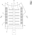
- Figure 1 shows a plan view of a room 2 containing a heat source 4 and a ventilation and air conditioning system 6.
- Room 2 is specifically a technical room in a nuclear power plant.
- the heat source 4 comprises several electrical and electronic components 8, in particular control and regulation components, which generate heat during operation.
- the control and regulation components 8 are housed, for example, in cabinets 10, for example, in a central area of the room 2.
- the heat source 4 is of a different type than the electrical/electronic components described so far.
- the ventilation and air conditioning system 6 blows cooled air into room 2 during operation to keep the room temperature below an acceptable maximum value.
- the room temperature should be kept below 25 °C during continuous operation.
- a heater is also integrated, resulting in a combined heating, ventilation and air conditioning system.
- the ventilation and air conditioning system 6 comprises a cooling air supply system 12, a supply air duct system 14 connected to the cooling air supply system 12 and at least one housing 16 comprising an inlet 18 and an outlet 20.
- the cooling air supply system 12 comprises, for example, an air cooler, which may be a refrigeration machine with a vapor compression cycle or with thermoelectric cooling, and a fan or blower for generating a forced flow of cooled air through the supply air duct system 14.
- an air cooler which may be a refrigeration machine with a vapor compression cycle or with thermoelectric cooling
- a fan or blower for generating a forced flow of cooled air through the supply air duct system 14.
- the cooling air supply system 12 produces cooled air with a temperature between 15 and 20°C.
- the Figure 1 The cooling air supply system 12, which is only indicated schematically, is arranged outside the room 2, for example.
- a forced flow of cooled air occurs from the cooling air supply system 12 through the supply air duct system 14.
- the supply air duct system 14 is configured to direct the forced flow of cooled air from the cooling air supply system 12 to the inlet 18 of the housing 16 during operation of the cooling air supply system 12.
- the ventilation and air conditioning system 6 comprises a plurality of housings 16, which are preferably arranged in parallel.
- the housings 16 are preferably arranged in a row and preferably on a wall 34 of the room 2.
- the housings 16 are arranged, for example, in two parallel rows on two opposite walls 34 of the room 2.
- the housings 16 are arranged in the middle of the space 2 and in particular between the various components 8.
- the supply air duct system 14 comprises at least one air duct 22.
- the air duct 22 is an air hose made of textile material.
- Textile material is understood to mean, for example, a textile fabric, in particular a textile fabric made of Polyester. This type of textile fabric made of polyester offers good resistance to environmental and chemical influences and is easy to wash and clean.
- a metallic air duct 22 can be used.
- the air duct 22 directs the forced flow of cooled air from the cooling air supply system 12 to each of the housings 16.
- the air duct 22 comprises, for example, a branch for each row of housings 16.
- the supply air duct system 14 comprises a plurality of air ducts 22, for example one air duct 22 for each row of housings 16.
- the air hose 22 preferably has a circular cross-section as shown in the figures. Such a cross-section ensures uniform air distribution.
- the air hose 22 has a semicircular cross-section.
- the air hose 22 for example, has a diameter of between 300 mm and 800 mm.
- the air hose 22 is preferably permeable over its entire surface. This means that a portion of the forced flow of cooled air can escape at any point along the air hose 22.
- the supply air duct system 14 preferably includes supporting openings 24 that, during operation of the cooling air supply system 12, direct the forced flow of cooled air from the cooling air supply system 12 to the inlet 18 of a respective housing 16.
- At least one opening 24 is arranged opposite the inlet 18 of each housing 16.
- the openings 24 are preferably formed by nozzles. These nozzles 24 are preferably located on the underside of the air hose 22. Each nozzle 24 directs a stream of cooled air toward the inlet 18 of one of the housings 16. These nozzles can be, for example, full-cone nozzles that direct a cone of cooled air toward the respective inlet 18, or coneless nozzles, or opening nozzles punched into the air hose.
- the nozzles 24 assist the flow by directing the forced flow of cooled air to the inlet 18 of a respective housing 16.
- the openings 24 can be formed by nozzles or exhaust grilles. In this case, the openings 24 are preferably the only air outlets from the air duct 22 for the forced flow of cooled air.
- the supply air duct system 14 is advantageously arranged near a ceiling 26 of the room 2, for example at a distance of at most 20 cm from the ceiling 26.
- the ventilation and air conditioning system 6 comprises a bracket 28 for suspending the supply air duct system 14 from the ceiling 26 of the room 2.
- the support 28 comprises, for example, a cable suspension, preferably as shown in Figure 4 shown, a two-sided cable suspension.
- the bracket 28 comprises a suspension rail.
- each housing 16 includes a bracket for receiving the supply air duct system 14.
- the supply air duct system 14 does not require a separate suspension to the ceiling 26.
- Each housing 16 includes heat storage elements 30 arranged within the housing 16 between the inlet 18 and the outlet 20. Since each housing 16 is substantially identical, only one housing 16 will be referred to below with reference to Figure 4 described.
- the housing 16 preferably consists of a straight, vertically oriented section which directs a downward air flow during cooling operation.
- the housing 16 comprises side walls 32 (facing the room and wall side) which extend vertically between the inlet 18 and the outlet 20.
- These perforated metal panels 36 define access doors to the housing 16, for example for maintenance work.
- the perforated sheet metal panels 36 are dimensioned with their hole pattern in such a way that the heat storage elements 30 in the housing 16 can also absorb part of the direct heat radiation if the active cooling air flow fails.
- the inlet 18 is located at the upper end of the housing 16, in particular below the supply air duct system 14.
- the supply air duct system 14 is arranged above the inlet 18 at a distance A therefrom, with a gap 38 defined between the supply air duct system 14 and the inlet 18.
- the distance A is measured along the vertical direction.
- the inlet 18 of the housing 16 is constantly in flow connection with the space 2, in that air from the space 2 can flow through the gap 38 into the inlet 18 of the housing 16.
- the distance A should be chosen so large that sufficient air can flow from the space 2 between the inlet 18 and the air duct 22, while at the same time is chosen small enough to ensure that little cooled air is lost from the openings 24.
- the distance A is, for example, between 50 mm and 250 mm.
- the housing 16 includes a baffle 40 disposed at an upper end of the housing 16, which directs air from the space 2 into the inlet 18 of the housing 16.
- the baffle 40 is configured to direct air from an upper region of the space 2, e.g., warm air, to the gap 38, while simultaneously preventing cooled air from the openings 24 from flowing through the gap 38 into the space 2. This means that the forced flow of cooled air from the openings 24 can flow almost entirely through the inlet 18 into the housing 16.
- the outlet 20 leads into the chamber 2 and forms the exit point of the air from the housing 16.
- the outlet 20 is arranged, as shown in the figures, near a floor 41 of the chamber 2.
- the outlet 20 comprises, for example, a grille 42.
- the housing 16 comprises a support structure 44 arranged inside the housing 16.
- the heat storage elements 30 are arranged inside the housing 16 with the aid of the support structure 44 such that, during normal operation, they are subjected to the forced flow of cooled air provided by the cooling air supply system 12.
- the heat storage elements 30 create a certain pressure drop, the remaining free space between the heat storage elements 30 and/or between the heat storage elements 30 and the side walls 32 of the housing 16 ensures that the air flow between the inlet 18 and the outlet 20 is not blocked.
- a plurality of heat storage elements 30 are arranged parallel and/or one behind the other with respect to the flow direction in the interior of the housing 16.
- the cooling air supply system 12 fails, for example due to a power failure, the cooling air supply system 12 and the exhaust air system 48 do not generate a forced flow of cooled air, and therefore no cooled air flows from the supply air duct system 14 into the inlet 18 of the housing or housings 16. In this case, the temperatures in the room 2 and between the components 8 can relatively quickly exceed a critical value.
- the passive emergency cooling operation is in Figure 3 shown schematically by arrows indicating the flow direction.
- Heated air with a temperature in the range of, for example, 24°C to 52°C rises to the ceiling and, due to the temperature difference with the cooled interior of the housing or housings 16, enters the or each cooled housing 16 via the respective inlet 18 as a natural convection airflow.
- the heated air then flows through the housing(s) 16, and in particular through the heat storage elements 30, and cools.
- the PCM 46 of the heat storage elements 30 is heated by the warm air flow flowing through it, thereby changing its state from solid to liquid (melting).
- the phase change of the PCM 46 and the associated latent heat allow a relatively large heat storage capacity to be achieved.
- the heat storage elements 30 thus act as latent heat storage devices and provide cooling power for the natural convection air flow.
- the temperature of the PCM 46 is kept approximately constant until it completely melts.
- the cooled air exits the respective outlet 20 in the bottom area of the or each housing 16 and is distributed by natural air flow to the heat-generating components 8 in order to cool them.
- the ventilation and air conditioning system 6 is configured such that when the operation of the cooling air supply system 12 fails, a natural convection air flow occurs through the housing(s) 16 from the respective inlet 18 to the respective outlet 20, the natural convection air flow being cooled by transferring heat to the heat storage elements 30.
- cooling air supply system 12 If the cooling air supply system 12 is put back into operation, for example, when the electrical power is switched on again, a forced flow of cooled air through the housing(s) 16 is restored, and the heat storage elements 30 are therefore frozen again.
- the switch from natural convection air flow to forced air flow also occurs without any additional active or passive function.
- This ventilation and air conditioning system 6 ensures inherently safe cooling of the room for a certain grace period, even in the event of a power failure.
- the inventors conducted tests and numerical calculations with a system according to the invention, wherein the system comprised a total of twelve housings 16, each housing containing a stack of 180 salt hydrate PCM heat storage elements 30.
- Each heat storage element 30 had dimensions of approximately 450 x 300 x 15 mm, a weight of approximately 630 kg (including housing and base frame), and a heat capacity of approximately 83,000 kJ.
Landscapes
- Engineering & Computer Science (AREA)
- General Engineering & Computer Science (AREA)
- Chemical & Material Sciences (AREA)
- Combustion & Propulsion (AREA)
- Mechanical Engineering (AREA)
- Microelectronics & Electronic Packaging (AREA)
- Aviation & Aerospace Engineering (AREA)
- Physics & Mathematics (AREA)
- Thermal Sciences (AREA)
- Life Sciences & Earth Sciences (AREA)
- Sustainable Development (AREA)
- Textile Engineering (AREA)
- Ventilation (AREA)
- Duct Arrangements (AREA)
Description
- Die vorliegende Erfindung betrifft ein Belüftungs- und Klimatisierungssystem für einen Raum.
- Moderne Regelungs- und Steuerungskomponenten und -Anlagen, insbesondere in Kernkraftwerken, erzeugen eine stärke Wärmeabgabe durch Konvektion und Strahlung in den Technikraum, in dem sie installiert sind. Deswegen ist die Kühlung solcher Räume immer wichtiger geworden.
- Normalerweise wird diese Kühlung durch ein aktives Belüftungs- und Klimatisierungssystem erreicht, das gekühlte Luft in den Technikraum bläst. Bei einem Ausfall der aktiven Kühlfunktion erreichen die im Raum vorhandenen Anlagen die maximal zulässige Temperatur jedoch typischerweise nach nur circa 2 Stunden.
- Es ist, insbesondere aus der
WO 2019/105559 , bekannt, einen passiven Notkühlbetrieb vorzusehen, um die Zeit (im Folgenden als "Karenzzeit" bezeichnet), in der die im Raum vorhandenen Anlagen die maximal zulässige Temperatur erreichen, zum Beispiel auf bis zu 24 Stunden, zu erhöhen. Dies wird zum Beispiel durch das Vorsehen eines passiven Systems mit Phasenwechselmaterialien erreicht, das als Wärmespeicher wirkt. - Die Patentschrift
EP 2 686 616 A1 zeigt ein Belüftungs- und Klimatisierungssystem mit den Merkmalen des Oberbegriffs von Anspruch 1. - Allerdings sind solche Systeme, insbesondere in Bezug auf deren Robustheit und Zuverlässigkeit, nicht ganz zufriedenstellend. In der Tat verwenden solche Systeme Zwischenteile, insbesondere zur Umschaltung vom aktiven auf den passiven Kühlbetrieb. Diese Zwischenteile können beschädigt werden, oder über längere Zeit im Standby ihre Funktion einbüßen, was die Zuverlässigkeit solcher Systeme verringert.
- Die vorliegende Erfindung hat zum Ziel, einen Notkühlbetrieb für ein aktives Belüftungs- und Klimatisierungssystem bei Ausfall der aktiven Kühlfunktion, insbesondere durch Stromausfall, bereitzustellen. Insbesondere soll die bisherige Karenzzeit verlängert werden. Das System soll zuverlässig arbeiten und einfach zu installieren und zu warten sein.
- Zu diesem Zweck schlägt die Erfindung ein Belüftungs- und Klimatisierungssystem vor, das die Merkmale des Anspruches 1 aufweist.
- Die Grundidee ist eine passive Umschaltung von aktiver Raumkühlung auf passive Raumkühlung mit Hilfe von Wärmespeicherelementen. Es erfolgt eine passive Umschaltung von einem Zwangskühlbetrieb, bei dem die Wärmespeicherelemente innerhalb des Gehäuses gekühlt werden, auf einen natürlichen Konvektionskühlbetrieb, bei dem die zuvor gekühlten Wärmespeicherelemente Kühlleistung für den natürlichen Konvektionsluftstrom bereitstellen. Außerdem, erfolgt diese Umschaltung ohne zusätzliche Maßnahmen oder zusätzliche Komponenten, was die Robustheit, und somit die Zuverlässigkeit, des Systems erhöht.
- Vorteilhafte Ausgestaltungen sind in den Unteransprüchen sowie in der Beschreibung angegeben.
- Die vorliegende Erfindung betrifft ebenfalls ein Gebäude, welches einen Raum umfasst, wobei der Raum eine Wärmequelle und ein Belüftungs- und Klimatisierungssystem wie vorstehend beschrieben umfasst.
- Die Erfindung wird anhand der folgenden Beschreibung eines Ausführungsbeispiels erläutert, das Bezug auf die angehängten Zeichnungen nimmt.
- Bevorzugte Ausführungsformen der Erfindung werden nun anhand der Zeichnungen im Detail beschrieben, wobei:
-
Figur 1 zeigt eine Draufsicht auf einen Raum, der eine Reihe von elektrischen oder elektronischen Regelungs- und Steuerungskomponenten enthält, die im Betrieb Wärme erzeugen. -
Figur 2 zeigt eine seitliche Schnittansicht des Raums entlang der inFigur 1 angedeuteten Schnittlinie II-II in dem ein erfindungsgemäßes Belüftungs- und Klimatisierungssystem installiert ist und in dem ein aktiver Normalkühlbetrieb durch Pfeile, die den Luftstrom anzeigen, visualisiert wird. -
Figur 3 zeigt die seitliche Schnittansicht vonFigur 2 , in der ein passiver Notkühlbetrieb visualisiert ist. -
Figur 4 zeigt eine detailliertere Schnittansicht eines inFigur 2 undFigur 3 dargestellten Belüftungs- und Klimatisierungssystems. -
Figur 1 zeigt eine Draufsicht auf einen Raum 2, der eine Wärmequelle 4 und ein Belüftungs- und Klimatisierungssystem 6 enthält. - Der Raum 2 ist insbesondere ein Technikraum in einem Kernkraftwerk.
- Die Wärmequelle 4 umfasst mehrere elektrische und elektronische Komponenten 8, insbesondere Regelungs- und Steuerungskomponenten, die im Betrieb Wärme erzeugen. Die Regelungs- und Steuerungskomponenten 8 sind beispielhaft in Schränken 10, zum Beispiel, in einem zentralen Bereich des Raumes 2 untergebracht.
- Alternativ ist die Wärmequelle 4 von einem anderen Typ als die bisher beschriebenen elektrischen / elektronischen Komponenten.
- Das Belüftungs- und Klimatisierungssystem 6 bläst während des Betriebs gekühlte Luft in den Raum 2 ein, um die Raumtemperatur unter einem akzeptablen Maximalwert zu halten.
- Die Raumtemperatur soll im Dauerbetrieb zum Beispiel unter 25 °C gehalten werden.
- In einigen Ausführungsformen ist zusätzlich eine Heizung integriert, wodurch sich ein kombiniertes Heizungs-, Belüftungs- und Klimatisierungssystem ergibt.
- Das Belüftungs- und Klimatisierungssystem 6 umfasst ein Kühlluftzufuhrsystem 12, ein an das Kühlluftzufuhrsystem 12 angeschlossenes Zuluftkanalsystem 14 und mindestens ein Gehäuse 16, das einen Einlass 18 und einen Auslass 20 umfasst.
- Das Kühlluftzufuhrsystem 12 umfasst beispielsweise einen Luftkühler, der zum Beispiel durch eine Kältemaschine mit Dampfkompressionskreislauf oder mit thermoelektrischer Kühlung, und einen Ventilator oder ein Gebläse zur Erzeugung eines Zwangsstroms gekühlter Luft durch das Zuluftkanalsystem 14.
- Das Kühlluftzufuhrsystem 12 erzeugt zum Beispiel gekühlte Luft mit einer Temperatur zwischen 15 und 20°C.
- Das in
Figur 1 nur schematisch angedeutete Kühlluftzufuhrsystem 12 ist zum Beispiel außerhalb des Raumes 2 angeordnet. - Während des Betriebs des Kühlluftzufuhrsystems 12 erfolgt einen Zwangsstrom gekühlter Luft von dem Kühlluftzufuhrsystem 12 durch das Zuluftkanalsystem 14.
- Das Zuluftkanalsystem 14 ist so konfiguriert, dass es während des Betriebs des Kühlluftzufuhrsystems 12 den Zwangsstrom gekühlter Luft von dem Kühlluftzufuhrsystem 12 zum Einlass 18 des Gehäuses 16 leitet.
- In dem in
Figur 1 gezeigten Ausführungsbeispiel umfasst das Belüftungs- und Klimatisierungssystem 6 mehrere Gehäuse 16, welche vorzugsweise in paralleler Anordnung angeordnet sind. - Wie in
Figur 1 gezeigt, sind die Gehäuse 16 vorzugsweise in einer Reihe und vorzugsweise an einer Wand 34 des Raumes 2 angeordnet. - Die Gehäuse 16 sind beispielhaft in zwei parallelen Reihen an zwei gegenüberliegenden Wänden 34 des Raumes 2 angeordnet.
- Alternativ sind die Gehäuse 16 in der Mitte des Raumes 2 und insbesondere zwischen den verschiedenen Komponenten 8 angeordnet.
- Das Zuluftkanalsystem 14 umfasst entsprechende Abzweigungen zu jedem dieser Gehäuse 16.
- Das Zuluftkanalsystem 14 umfasst mindestens einen Luftkanal 22.
- Bevorzugt ist der Luftkanal 22 ein Luftschlauch aus textilem Material. Unter textilem Material versteht man beispielsweise ein Textilgewebe, insbesondere ein Textilgewebe aus Polyester. Ein solches Textilgewebe aus Polyester bietet eine gute Beständigkeit gegen Umwelt- und chemische Einflüsse und ist leicht wasch- bzw. reinigbar.
- Alternativ kann auch ein metallischer Luftkanal 22 verwendet werden.
- Der Luftkanal 22 leitet den Zwangsstrom gekühlter Luft von dem Kühlluftzufuhrsystem 12 zu jedem der Gehäuse 16.
- Zu diesem Zweck umfasst der Luftkanal 22 beispielsweise einen Abzweig für jede Reihe von Gehäusen 16.
- Alternativ umfasst das Zuluftkanalsystem 14 mehrere Luftkanäle 22, zum Beispiel einen Luftkanal 22 für jede Reihe von Gehäusen 16.
- Falls der Luftkanal 22 ein Luftschlauch aus textilem Material ist, hat der Luftschlauch 22 vorzugsweise einen kreisförmigen Querschnitt wie in den Figuren dargestellt. Ein solcher Querschnitt gewährleistet eine gleichmäßige Luftverteilung. Alternativ hat der Luftschlauch 22 einen halbkreisförmigen Querschnitt.
- Der Luftschlauch 22 hat beispielsweise einen Durchmesser von zwischen 300 mm und 800 mm.
- Der Luftschlauch 22 ist vorzugsweise vollflächig durchlässig. Das bedeutet, dass ein Teil des Zwangsstroms gekühlter Luft an jeder Stelle des Luftschlauchs 22 ausströmen kann. Das Zuluftkanalsystem 14 umfasst vorzugsweise unterstützende Öffnungen 24, die während des Betriebs des Kühlluftzufuhrsystems 12 den Zwangsstrom gekühlter Luft aus dem Kühlluftzufuhrsystem 12 zum Einlass 18 eines jeweiligen Gehäuses 16 leiten.
- Vorzugsweise ist mindestens eine Öffnung 24 gegenüber dem Einlass 18 jedes Gehäuses 16 angeordnet.
- Falls der Luftkanal 22 ein Luftschlauch aus textilem Material ist, werden die Öffnungen 24 vorzugsweise durch Düsen gebildet. Diese Düsen 24 befinden sich bevorzugt an der Unterseite des Luftschlauchs 22. Jede Düse 24 richtet einen Strom gekühlter Luft auf den Einlass 18 eines der Gehäuse 16. Es handelt sich dabei beispielsweise um Vollkegeldüse, die einen Kegel gekühlter Luft auf den jeweiligen Einlass 18 richtet, oder auch kegellose Düsen, oder in den Luftschlauch gestanzte Öffnungsdüsen.
- Die Düsen 24 unterstützen die Strömung, indem sie den Zwangsstrom gekühlter Luft zum Einlass 18 eines jeweiligen Gehäuses 16 richten.
- Falls der Luftkanal 22 ein metallischer Luftkanal ist, können die Öffnungen 24 durch Düsen oder Ausblasgitter gebildet werden. In diesem Fall, sind die Öffnungen 24 bevorzugt die einzigen Luftauslässe aus dem Luftkanal 22 für den Zwangsstrom gekühlter Luft.
- Wie in den
Figuren 2 und3 gezeigt ist das Zuluftkanalsystem 14 vorteilhafterweise in der Nähe einer Decke 26 des Raumes 2 angeordnet, zum Beispiel in einem Abstand von höchstens 20 cm zur Decke 26. - Zu diesem Zweck umfasst das Belüftungs- und Klimatisierungssystem 6 eine Halterung 28 zur Aufhängung des Zuluftkanalsystems 14 an der Decke 26 des Raumes 2.
- Die Halterung 28 umfasst, zum Beispiel, eine Seilaufhängung, vorzugsweise, wie in
Figur 4 dargestellt, eine zweiseitige Seilaufhängung. Alternativ umfasst die Halterung 28 eine Aufhängeschiene. - Alternativ umfasst jedes Gehäuse 16 eine Halterung zur Aufnahme des Zuluftkanalsystems 14. In diesem Fall benötigt das Zuluftkanalsystem 14 keine separate Aufhängung zur Decke 26.
- Jedes Gehäuse 16 umfasst Wärmespeicherelemente 30, die innerhalb des Gehäuses 16 zwischen dem Einlass 18 und dem Auslass 20 angeordnet sind. Da jedes Gehäuse 16 im Wesentlichen identisch ist, wird im Folgenden nur ein Gehäuse 16 mit Bezug auf
Figur 4 beschrieben. - Das Gehäuse 16 besteht vorzugsweise aus einem geradlinigen, vertikal ausgerichteten Abschnitt, der im Kühlbetrieb einen nach unten gerichteten Luftstrom leitet.
- Das Gehäuse 16 umfasst Seitenwände 32 (zum Raum gerichtet und wandseitig), die sich vertikal zwischen dem Einlass 18 und dem Auslass 20 erstrecken.
- In dem in den Figuren dargestellten Beispiel steht eine der Seitenwände 32 an der Wand 34 des Raumes 2.
- Das Gehäuse 16 umfasst Lochblechpaneele 36, die mindestens eine Seitenwand 32 des Gehäuses 16 bilden, und insbesondere die Seitenwand 32 des Gehäuses 16 bilden, die entfernt von der Wand 34 des Raumes 2 angeordnet ist.
- Diese Lochblechpaneele 36 definieren Zugangstüren zum Gehäuse 16, zum Beispiel für Wartungsarbeiten.
- Die Lochblechpaneelen 36 sind mit ihrem Lochbild so dimensioniert, dass die Wärmespeicherelemente 30 im Gehäuse 16 bei Ausfall des aktiven Kühlluftstroms auch einen Teil direkte Wärmestrahlung aufnehmen können.
- Der Einlass 18 befindet sich an dem oberen Ende des Gehäuses 16, insbesondere unter dem Zuluftkanalsystem 14.
- Das Zuluftkanalsystem 14 ist oberhalb des Einlasses 18 in einem Abstand A zu diesem angeordnet, wobei ein Spalt 38 zwischen dem Zuluftkanalsystem 14 und dem Einlass 18 definiert ist. Der Abstand A wird entlang der vertikalen Richtung gemessen.
- Dank diesem Abstand A steht der Einlass 18 des Gehäuses 16 ständig in Strömungsverbindung mit dem Raum 2, indem Luft aus dem Raum 2 durch den Spalt 38 in den Einlass 18 des Gehäuses 16 strömen kann.
- Der Abstand A sollte so groß gewählt werden, dass genügend Luft aus dem Raum 2 zwischen dem Einlass 18 und dem Luftkanal 22 hindurchströmen kann, während er gleichzeitig klein genug gewählt wird, um sicherzustellen, dass wenig gekühlte Luft aus den Öffnungen 24 verloren geht. Das Abstand A liegt zum Beispiel zwischen 50 mm und 250 mm.
- Vorteilhafterweise, wie in
Figur 4 dargestellt, umfasst das Gehäuse 16 ein an einem oberen Ende des Gehäuses 16 angeordnetes Leitblech 40, das Luft aus dem Raum 2 in den Einlass 18 des Gehäuses 16 leitet. Das Leitblech 40 ist so konfiguriert, dass es Luft aus einem oberen Bereich des Raumes 2, z. B. Warmluft, zu dem Spalt 38 leitet, während es gleichzeitig verhindert, dass gekühlte Luft aus den Öffnungen 24 durch den Spalt 38 in den Raum 2 strömt. Das bedeutet, dass der Zwangsstrom gekühlter Luft aus den Öffnungen 24 fast vollständig durch den Einlass 18 in das Gehäuse 16 strömen kann. - Luft aus dem Raum 2, insbesondere erwärmte Luft im Notkühlbetrieb, wird durch das Leitblech 40 zum Einlass 18 geführt und strömt danach durch das Gehäuse 16. Dadurch entsteht auf einfache Art und Weise eine zuverlässige Notkühlung des Raumes 2 im Falle eines Ausfalls des Kühlluftzufuhrsystems 12.
- Der Auslass 20 führt in den Raum 2 und bildet den Austrittspunkt der Luft aus dem Gehäuse 16. Der Auslass 20 ist, wie in Figuren gezeigt, in der Nähe eines Bodens 41 des Raumes 2 angeordnet. Der Auslass 20 umfasst beispielsweise ein Gitter 42.
- Das Gehäuse 16 umfasst eine Tragstruktur 44, welche im Inneren des Gehäuses 16 angeordnet ist. Die Wärmespeicherelemente 30 sind im Inneren des Gehäuses 16 mit Hilfe der Tragstruktur 44 so angeordnet, dass sie im Normalbetrieb von dem durch das Kühlluftzufuhrsystem 12 bereitgestellten Zwangsstrom gekühlter Luft überströmt werden.
- Durch die Wärmespeicherelemente 30 entsteht zwar ein gewisser Druckabfall, aber der verbleibende Freiraum zwischen den Wärmespeicherelementen 30 und/oder zwischen den Wärmespeicherelementen 30 und die Seitenwände 32 des Gehäuses 16 sorgt dafür, dass der Luftstrom zwischen dem Einlass 18 und dem Auslass 20 nicht blockiert wird.
- Vorzugsweise weisen die Wärmespeicherelemente 30 eine Plattenform auf, insbesondere mit flachen Seiten, die parallel Hauptströmungsrichtung ausgerichtet sind.
- Gemäß einer Ausführungsform sind mehrere Wärmespeicherelemente 30 parallel und/oder hintereinander in Bezug auf die Strömungsrichtung im Inneren des Gehäuses 16 angeordnet.
- Die Wärmespeicherelemente 30 bestehen vorzugsweise aus einem Phasenwechselmaterial (PCM) 46.
- Das PCM 46 der Wärmespeicherelemente 30 ist vorzugsweise so gewählt, dass es bei Kontakt mit dem Zwangsstrom gekühlter Luft des Kühlluftzufuhrsystems 12, der typischerweise eine Temperatur im Bereich von 16 °C bis 30 °C hat, einfriert.
- Das PCM 46 ist auch so gewählt, dass es einen Phasenwechsel von fest zu flüssig im Temperaturbereich von 16 °C bis 30°C ausführt.
- Anders gesagt, schmilzt das PCM 46 vorzugsweise bei natürlicher Konvektion mit einer Schmelztemperatur im Bereich von 16 °C bis 30 °C.
- Bei diesem Gefrieren / Schmelzen ist die Hysterese zu berücksichtigen.
- Das PCM 46 basiert vorzugsweise auf Salzhydraten, da Salzhydrate nicht oder zumindest schwer entflammbar sind. Außerdem weisen Salzhydrate keinen Memory-Effekt auf, der ihre Wärmespeicherfähigkeit bei mehreren Gefrier- und Schmelzzyklen negativ beeinflusst. Salzhydrate haben außerdem eine hohe volumetrische Latentwärmespeicherkapazität.
- Alternativ basiert das PCM 46 auf Paraffinen.
- Es folgt nun die Beschreibung des Normalkühlbetriebs des Belüftungs- und Klimatisierungssystems 6, d. h. während des Betriebs des Kühlluftzufuhrsystems 12, mit Bezug auf
Figur 2 . - In
Figur 2 ist der Luftstrom durch die Gehäuse 16 und durch den Raum 2 durch entsprechende Pfeile schematisch gezeigt. - Das Kühlluftzufuhrsystem 12 erzeugt einen Zwangsstrom gekühlter Luft. Dieser Zwangsstrom gekühlter Luft wird dann durch das Zuluftkanalsystem 14 verteilt. Das Zuluftkanalsystem 14, und insbesondere die unterstützenden Öffnungen 24 im Luftkanal 22, leiten den Zwangsstrom gekühlter Luft von der Kühlluftzufuhr zum Einlass 18 des Gehäuses oder der Gehäuse 16. Der Zwangsstrom gekühlter Luft fließt dann durch das oder die Gehäuse 16, und kühlt somit im Normalkühlbetrieb die Wärmespeicherelemente 30 ab, friert sie ein und bereitet sie für einen anschließenden etwaigen Notkühlbetrieb vor.
- Im Normalkühlbetrieb werden die Wärmespeicherelemente 30 ständig gekühlt, und können dadurch Kälte speichern.
- Vorzugsweise wird aus Sicherheitsgründen die Temperatur vor und nach den Wärmespeicherelementen 30 gemessen, um daraus deren Wärmespeicherkapazität abzuleiten.
- Nach dem Durchfluss durch die Wärmespeicherelemente 30 tritt die gekühlte Luft am jeweiligen Auslass 20 aus dem oder jedem Gehäuse 16 aus und wird dann durch natürlichen Luftstrom im Boden an die Schränke 10 verteilt. Aufgrund der höheren Dichte der gekühlten Luft hält sich der Luftstrom auf einem niedrigen Raumniveau, insbesondere in der Nähe des Bodens.
- Die Luft im Raum wird durch die Wärmeabgabe der Komponenten 8 erwärmt und steigt in Richtung der Raumdecke auf. Die erwärmte Luft wird dann durch ein Abluftsystem 48 unter der Decke 26 aus dem Raum 2 abgeführt.
- Im Normalkühlbetrieb wird die erwärmte Luft daher fast ausschließlich durch das Abluftsystem 48 des Raumes 2 abgeführt und es tritt nur eine vernachlässigbare Menge an erwärmter Luft durch den jeweiligen Einlass 18 in das oder jedes Gehäuse 16 ein.
- Wie oben beschrieben, ist das Belüftungs- und Klimatisierungssystem 6 so konfiguriert, dass während des Betriebs des Kühlluftzufuhrsystems 12 ein Zwangsstrom gekühlter Luft von dem Kühlluftzufuhrsystems 12 durch das Zuluftkanalsystem 14 und dann durch das oder die Gehäuse 16 vom jeweiligen Einlass 18 zum jeweiligen Auslass 20 erfolgt, wodurch die Wärmespeicherelemente 30 gekühlt und vorzugsweise eingefroren werden.
- Es folgt nun die Beschreibung des Notkühlbetriebs des Belüftungs- und Klimatisierungssystems 6, d. h. wenn der Betrieb des Kühlluftzufuhrsystems ausfällt, mit Bezug auf die
Figuren 3 und4 . - Fällt das Kühlluftzufuhrsystem 12 z. B. aufgrund eines Stromausfalls aus, erzeugen das Kühlluftzufuhrsystem 12 und das Abluftsystem 48 keinen Zwangsstrom gekühlter Luft, und es fließt daher keine gekühlte Luft vom Zuluftkanalsystem 14 in den Einlass 18 des Gehäuses oder der Gehäuse 16. In diesem Fall können die Temperaturen im Raum 2 und zwischen den Komponenten 8 relativ schnell einen kritischen Wert überschreiten.
- Der passive Notkühlbetrieb ist in
Figur 3 durch Pfeile, die die Strömungsrichtung angeben, schematisch gezeigt. - Erwärmte Luft mit einer Temperatur im Bereich von z. B. 24 °C bis 52 °C steigt an die Raumdecke auf und tritt durch Konvektion aufgrund des Temperaturunterschiedes zu dem gekühlten Inneren des Gehäuses oder die Gehäuse 16, über den jeweiligen Einlass 18 als natürlicher Konvektionsluftstrom in das oder jedes gekühlte Gehäuse 16 ein. Die erwärmte Luft strömt dann durch das oder die Gehäuse 16, und insbesondere durch die Wärmspeicherelemente 30, und kühlt sich ab.
- Die Umschaltung von Zwangsstrom auf natürlichen Luftstrom erfolgt somit ohne zusätzliche aktive oder passive Funktion.
- Während des passiven Kühlvorgangs wird das PCM 46 der Wärmespeicherelemente 30 durch den durchströmenden Warmluftstrom erwärmt und ändert dabei seinen Zustand von fest zu flüssig (Schmelzen). Durch den Phasenwechsel des PCM 46 und die damit verbundene latente Wärme kann eine relativ große Wärmespeicherkapazität erreicht werden. Die Wärmespeicherelemente 30 wirken somit als Latentwärmespeicher und stellen Kühlleistung für den natürlichen Konvektionsluftstrom zur Verfügung. Somit wird die Temperatur des PCM 46 bis zum vollständigen Aufschmelzen annähernd konstant gehalten.
- Wie beim Normalkühlbetrieb tritt die gekühlte Luft am jeweiligen Auslass 20 im Bodenbereich das oder jedes Gehäuse 16 aus und wird durch natürlichen Luftstrom auf die wärmeerzeugenden Komponenten 8 verteilt, um diese abzukühlen.
- Auf diese Weise wird ein natürlicher Konvektionsluftstrom durch den Raum 2 und durch das oder die Gehäuse 16 aufgebaut und unterstützt, solange die Kühlleistung der Wärmespeicherelemente 30 nicht überschritten wird.
- Wie oben beschrieben, ist das Belüftungs- und Klimatisierungssystem 6 so konfiguriert, dass wenn der Betrieb des Kühlluftzufuhrsystems 12 ausfällt, ein natürlicher Konvektionsluftstrom durch das oder die Gehäuse 16 vom jeweiligen Einlass 18 zum jeweiligen Auslass 20 auftritt, wobei der natürliche Konvektionsluftstrom durch Übertragung von Wärme an die Wärmespeicherelemente 30 gekühlt wird.
- Falls die Kühlluftzufuhrsystem 12 wieder im Betrieb genommen wird, zum Beispiel beim Wiedereinschalten der elektrischen Leistung, stellt sich wieder ein Zwangsstrom gekühlter Luft durch das oder die Gehäuse 16 ein und die Wärmespeicherelemente 30 werden daher wieder eingefroren. Die Umschaltung von natürlichen Konvektionsluftstrom auf Zwangsstrom erfolgt ebenfalls ohne zusätzliche aktive oder passive Funktion.
- Dieses Belüftungs- und Klimatisierungssystem 6 gewährleistet eine inhärent sichere Kühlung des Raums für eine bestimmte Karenzzeit, sogar bei einem Stromausfall.
- Insgesamt wird dank des erfindungsgemässen Systems eine relativ lange Karenzzeit, zum Beispiel von bis zu 24 Stunden, der passiven (Not-)Kühlung nach dem Ausfall des Kühlluftzufuhrsystems 12 erreicht. Die genaue Karenzzeit hängt dabei insbesondere von der Anzahl der Wärmespeicherelemente 30, dem benutzten PCM 46 und der Geometrie des Gehäuses 16 ab.
- Die Erfinder haben Versuche und numerische Berechnungen mit einem erfindungsgemäßen System angestellt, wobei das System insgesamt zwölf Gehäuse 16 umfasste und jedes Gehäuses einen Stapel von 180 Salzhydrat-PCM-Wärmespeicherelementen 30 enthielt. Dabei hatte jedes Wärmespeicherelement 30 Maße von ca. 450 x 300 x 15 mm, ein Gewicht von ca. 630 kg (inkl. Gehäuse und Grundrahmen) und eine Wärmekapazität von ca. 83000 kJ. Diese Versuche und Berechnungen haben bestätigt, dass ein solches beispielhafte System eine Gesamtkühlleistung im Bereich von ca. 1000 MJ für einen Raum von ca. 72 m2 Fläche und 3,4 m Höhe mit ca. 11,5 kW Heizlast für mindestens 24 Stunden bereitstellen kann.
- Darüber hinaus sorgt die passive Umschaltung von Zwangsstrom auf natürlichen Luftstrom ohne zusätzliche Geräte oder Maßnahmen für die Robustheit und damit für die Zuverlässigkeit des Belüftungs- und Klimatisierungssystems 6.
Claims (14)
- - Belüftungs- und Klimatisierungssystem (6) für einen Raum (2), wobei der Raum (2) eine Wärmequelle (4) und das Belüftungs- und Klimatisierungssystem (6) enthält, wobei das Belüftungs- und Klimatisierungssystem (6) umfasst:• ein Kühlluftzufuhrsystem (12),• mindestens ein Gehäuse (16) umfassend:∘ einen Einlass (18), der an einem oberen Ende des Gehäuses (16) angeordnet ist,∘ einen Auslass (20), der dazu konfiguriert ist, in den Raum (2) zu führen, und∘ Wärmespeicherelemente (30), die innerhalb des Gehäuses (16) zwischen dem Einlass (18) und dem Auslass (20) angeordnet sind, und• ein an das Kühlluftzufuhrsystem (12) angeschlossenes Zuluftkanalsystem (14);wobei das Belüftungs- und Klimatisierungssystem (6) so konfiguriert ist, dass:• während des Betriebs des Kühlluftzufuhrsystems (12) ein Zwangsstrom gekühlter Luft von dem Kühlluftzufuhrsystem (12) durch das Zuluftkanalsystem (14) und dann durch das Gehäuse (16) vom Einlass (18) zum Auslass (20) erfolgt, wodurch die Wärmespeicherelemente (30) gekühlt und vorzugsweise eingefroren werden, und• wenn der Betrieb des Kühlluftzufuhrsystems (12) ausfällt, ein natürlicher Konvektionsluftstrom durch das Gehäuse (16) vom Einlass (18) zum Auslass (20) auftritt, wobei der natürliche Konvektionsluftstrom durch Übertragung von Wärme an die Wärmespeicherelemente (30) gekühlt wird,dadurch gekennzeichnet,dass das Zuluftkanalsystem (14) oberhalb des Einlasses (18) in einem Abstand (A) zu diesem angeordnet ist, wobei ein Spalt (38) zwischen dem Zuluftkanalsystem (14) und dem Einlass (18) definiert ist,dass der Einlass (18) des Gehäuses (16) dazu geeignet ist, ständig in Strömungsverbindung mit dem Raum (2) zu stehen, indem die Luft aus dem Raum (2) durch den Spalt (38) in den Einlass (18) des Gehäuses strömt.
- Belüftungs- und Klimatisierungssystem nach Anspruch 1, wobei das Zuluftkanalsystem (14) mindestens einen Luftkanal (22), bevorzugt einen Luftschlauch aus textilem Material, umfasst.
- Belüftungs- und Klimatisierungssystem nach Anspruch 2, wobei der Luftkanal (22) ein Luftschlauch aus textilem Material ist und einen kreisförmigen oder halbkreisförmigen Querschnitt hat.
- Belüftungs- und Klimatisierungssystem nach einem der Ansprüche 1 bis 3, wobei das Zuluftkanalsystem (14) unterstützende Öffnungen (24) umfasst, die während des Betriebs des Kühlluftzufuhrsystems (12) den Zwangsstrom gekühlter Luft von dem Kühlluftzufuhrsystem (12) zum Einlass (18) eines jeweiligen Gehäuses (16) leiten.
- Belüftungs- und Klimatisierungssystem nach einem der Ansprüche 1 bis 4, wobei das Belüftungs- und Klimatisierungssystem (6) mindestens eine Halterung (28) zur Aufhängung des Zuluftkanalsystems (14) an einer Decke (26) des Raumes (2) umfasst, oder jedes Gehäuse (16) eine Halterung zur Aufnahme des Zuluftkanalsystems (14) umfasst.
- Belüftungs- und Klimatisierungssystem nach einem der Ansprüche 1 bis 5, wobei das Gehäuse (16) Lochblechpaneele (36) umfasst, die mindestens eine Seitenwand (32) des Gehäuses (16) bilden.
- Belüftungs- und Klimatisierungssystem nach einem der Ansprüche 1 bis 6, wobei das Gehäuse (16) ein an einem oberen Ende des Gehäuses (16) angeordnetes Leitblech (40) umfasst, das dazu geeignet ist, die Luft aus dem Raum (2) in den Einlass (18) des Gehäuses (16) zu leiten.
- Belüftungs- und Klimatisierungssystem nach einem der Ansprüche 1 bis 7, wobei die Wärmespeicherelemente (30) aus einem Phasenwechselmaterial (46) bestehen.
- Belüftungs- und Klimatisierungssystem nach Anspruch 8, wobei das Phasenwechselmaterial (46) einen Phasenwechsel von fest zu flüssig im Temperaturbereich von 16 °C bis 30°C ausführt.
- Belüftungs- und Klimatisierungssystem nach Anspruch 8 oder 9, wobei das Phasenwechselmaterial (46) auf Salzhydraten basiert.
- Belüftungs- und Klimatisierungssystem nach einem der Ansprüche 1 bis 10, wobei die Wärmespeicherelemente (30) eine Plattenform aufweisen.
- Gebäude umfassend einen Raum (2), wobei der Raum (2) eine Wärmequelle (4) und ein Belüftungs- und Klimatisierungssystem (6) nach einem der Ansprüche 1 bis 11 umfasst.
- Gebäude nach Anspruch 12, wobei der Auslass (20) in der Nähe eines Bodens (41) des Raumes (2) angeordnet ist.
- Gebäude nach Anspruch 12 oder 13, wobei die Wärmequelle (4) mehrere elektrische und elektronische Komponenten (8) umfasst.
Applications Claiming Priority (2)
| Application Number | Priority Date | Filing Date | Title |
|---|---|---|---|
| DE102021120799.1A DE102021120799B4 (de) | 2021-08-10 | 2021-08-10 | Belüftungs- und Klimatisierungssystem und Gebäude |
| PCT/EP2022/068702 WO2023016710A1 (de) | 2021-08-10 | 2022-07-06 | Belüftungs- und klimatisierungssystem |
Publications (2)
| Publication Number | Publication Date |
|---|---|
| EP4384755A1 EP4384755A1 (de) | 2024-06-19 |
| EP4384755B1 true EP4384755B1 (de) | 2025-07-02 |
Family
ID=82492833
Family Applications (1)
| Application Number | Title | Priority Date | Filing Date |
|---|---|---|---|
| EP22740865.5A Active EP4384755B1 (de) | 2021-08-10 | 2022-07-06 | Belüftungs- und klimatisierungssystem |
Country Status (8)
| Country | Link |
|---|---|
| US (1) | US20240353130A1 (de) |
| EP (1) | EP4384755B1 (de) |
| JP (1) | JP2024530200A (de) |
| KR (1) | KR20240047369A (de) |
| CN (1) | CN117795261A (de) |
| CA (1) | CA3228367A1 (de) |
| DE (1) | DE102021120799B4 (de) |
| WO (1) | WO2023016710A1 (de) |
Family Cites Families (5)
| Publication number | Priority date | Publication date | Assignee | Title |
|---|---|---|---|---|
| US20090126293A1 (en) * | 2007-11-16 | 2009-05-21 | Rocky Research | Telecommunications shelter with emergency cooling and air distribution assembly |
| EP2354687B1 (de) * | 2010-02-03 | 2012-09-26 | TROX GmbH | Deckenluftauslass für klimatechnische Anlagen |
| NL2006421C2 (en) * | 2011-03-18 | 2012-09-19 | Autarkis B V | Displacement ventilation system and inlet part for such a system. |
| GB2568043A (en) * | 2017-10-31 | 2019-05-08 | William Leaney Patrick | An air temperature adjustment device |
| US11678459B2 (en) * | 2017-11-30 | 2023-06-13 | Framatome Gmbh | Ventilation and air conditioning system with a passive emergency cooling mode |
-
2021
- 2021-08-10 DE DE102021120799.1A patent/DE102021120799B4/de active Active
-
2022
- 2022-07-06 CN CN202280054452.0A patent/CN117795261A/zh active Pending
- 2022-07-06 JP JP2024507978A patent/JP2024530200A/ja active Pending
- 2022-07-06 KR KR1020247004257A patent/KR20240047369A/ko active Pending
- 2022-07-06 US US18/682,429 patent/US20240353130A1/en active Pending
- 2022-07-06 WO PCT/EP2022/068702 patent/WO2023016710A1/de not_active Ceased
- 2022-07-06 EP EP22740865.5A patent/EP4384755B1/de active Active
- 2022-07-06 CA CA3228367A patent/CA3228367A1/en active Pending
Also Published As
| Publication number | Publication date |
|---|---|
| DE102021120799B4 (de) | 2025-05-28 |
| DE102021120799A1 (de) | 2023-02-16 |
| WO2023016710A1 (de) | 2023-02-16 |
| US20240353130A1 (en) | 2024-10-24 |
| KR20240047369A (ko) | 2024-04-12 |
| JP2024530200A (ja) | 2024-08-16 |
| EP4384755A1 (de) | 2024-06-19 |
| CN117795261A (zh) | 2024-03-29 |
| CA3228367A1 (en) | 2023-02-16 |
Similar Documents
| Publication | Publication Date | Title |
|---|---|---|
| DE19983613B4 (de) | Steuerverfahren, Anordnung, Geräteschrank und Betriebsverfahren | |
| DE69831281T2 (de) | Kältemittelverteileinheit für Klimaanlage | |
| EP2278231B1 (de) | Klimaanlage | |
| CH497880A (de) | Kühlanlage | |
| DE3717540C2 (de) | ||
| US3314353A (en) | Ventilated floor modular system | |
| EP4384755B1 (de) | Belüftungs- und klimatisierungssystem | |
| DE69912031T2 (de) | Vorrichtung zum Belüften, Kühlen und/oder Beheizen eines Raumes | |
| DE102011117988A1 (de) | Klimaschrank | |
| DE3926927C2 (de) | ||
| CH694620A5 (de) | Verfahren und Kühlgerät zum Kühlen von Arbeitsplätzen. | |
| DE954193C (de) | Belueftungseinrichtung mit einer Luftverteilungsoeffnungen aufweisenden Unterdecke | |
| DE102009053527B4 (de) | Klimaanlage | |
| EP3477212B1 (de) | Luftverteilvorrichtung sowie verfahren zur belüftung eines raumes | |
| EP0338343B1 (de) | Kühleinschubeinheit für Schalt- und Steuerschränke | |
| EP3587943B1 (de) | Vorrichtung zur belüftung und temperierung eines raums eines gebäudes | |
| WO2015180843A1 (de) | Klimatisierungsanordnung | |
| RU2849918C2 (ru) | Система вентиляции и кондиционирования воздуха | |
| EP3370491B1 (de) | Anordnung eines kühlsystems zur kühlung mindestens eines, in einem raum angeordneten serverschranks | |
| DE4409500C2 (de) | Verfahren zur Klimatisierung von Schaltschränken o. dgl. | |
| DE3151301A1 (de) | "schrank zur aufnahme von elektrischen bauelementen" | |
| EP2597382B2 (de) | Lufttechnisches Gerät | |
| DE19507918A1 (de) | Klimaanlage für Sicherheitscontainer zur Aufbewahrung von EDV-Geräten | |
| DE19626923C2 (de) | Anlage zum Kühlen von Räumen | |
| DE2846274A1 (de) | Verfahren und vorrichtung zum erwaermen eines raums |
Legal Events
| Date | Code | Title | Description |
|---|---|---|---|
| STAA | Information on the status of an ep patent application or granted ep patent |
Free format text: STATUS: UNKNOWN |
|
| STAA | Information on the status of an ep patent application or granted ep patent |
Free format text: STATUS: THE INTERNATIONAL PUBLICATION HAS BEEN MADE |
|
| PUAI | Public reference made under article 153(3) epc to a published international application that has entered the european phase |
Free format text: ORIGINAL CODE: 0009012 |
|
| STAA | Information on the status of an ep patent application or granted ep patent |
Free format text: STATUS: REQUEST FOR EXAMINATION WAS MADE |
|
| 17P | Request for examination filed |
Effective date: 20240305 |
|
| AK | Designated contracting states |
Kind code of ref document: A1 Designated state(s): AL AT BE BG CH CY CZ DE DK EE ES FI FR GB GR HR HU IE IS IT LI LT LU LV MC MK MT NL NO PL PT RO RS SE SI SK SM TR |
|
| DAV | Request for validation of the european patent (deleted) | ||
| DAX | Request for extension of the european patent (deleted) | ||
| GRAP | Despatch of communication of intention to grant a patent |
Free format text: ORIGINAL CODE: EPIDOSNIGR1 |
|
| STAA | Information on the status of an ep patent application or granted ep patent |
Free format text: STATUS: GRANT OF PATENT IS INTENDED |
|
| RIC1 | Information provided on ipc code assigned before grant |
Ipc: H05K 5/02 20060101ALI20250211BHEP Ipc: H05K 7/20 20060101ALI20250211BHEP Ipc: F24F 7/06 20060101ALI20250211BHEP Ipc: F24F 13/02 20060101ALI20250211BHEP Ipc: F24F 5/00 20060101AFI20250211BHEP |
|
| INTG | Intention to grant announced |
Effective date: 20250226 |
|
| GRAS | Grant fee paid |
Free format text: ORIGINAL CODE: EPIDOSNIGR3 |
|
| GRAA | (expected) grant |
Free format text: ORIGINAL CODE: 0009210 |
|
| STAA | Information on the status of an ep patent application or granted ep patent |
Free format text: STATUS: THE PATENT HAS BEEN GRANTED |
|
| AK | Designated contracting states |
Kind code of ref document: B1 Designated state(s): AL AT BE BG CH CY CZ DE DK EE ES FI FR GB GR HR HU IE IS IT LI LT LU LV MC MK MT NL NO PL PT RO RS SE SI SK SM TR |
|
| REG | Reference to a national code |
Ref country code: GB Ref legal event code: FG4D Free format text: NOT ENGLISH |
|
| REG | Reference to a national code |
Ref country code: CH Ref legal event code: EP |
|
| REG | Reference to a national code |
Ref country code: DE Ref legal event code: R096 Ref document number: 502022004532 Country of ref document: DE |
|
| REG | Reference to a national code |
Ref country code: IE Ref legal event code: FG4D Free format text: LANGUAGE OF EP DOCUMENT: GERMAN |
|
| PGFP | Annual fee paid to national office [announced via postgrant information from national office to epo] |
Ref country code: AT Payment date: 20251020 Year of fee payment: 4 Ref country code: FR Payment date: 20250731 Year of fee payment: 4 |
|
| REG | Reference to a national code |
Ref country code: NL Ref legal event code: MP Effective date: 20250702 |
|
| PG25 | Lapsed in a contracting state [announced via postgrant information from national office to epo] |
Ref country code: PT Free format text: LAPSE BECAUSE OF FAILURE TO SUBMIT A TRANSLATION OF THE DESCRIPTION OR TO PAY THE FEE WITHIN THE PRESCRIBED TIME-LIMIT Effective date: 20251103 |
|
| PG25 | Lapsed in a contracting state [announced via postgrant information from national office to epo] |
Ref country code: NL Free format text: LAPSE BECAUSE OF FAILURE TO SUBMIT A TRANSLATION OF THE DESCRIPTION OR TO PAY THE FEE WITHIN THE PRESCRIBED TIME-LIMIT Effective date: 20250702 |
|
| PG25 | Lapsed in a contracting state [announced via postgrant information from national office to epo] |
Ref country code: IS Free format text: LAPSE BECAUSE OF FAILURE TO SUBMIT A TRANSLATION OF THE DESCRIPTION OR TO PAY THE FEE WITHIN THE PRESCRIBED TIME-LIMIT Effective date: 20251102 |
|
| PG25 | Lapsed in a contracting state [announced via postgrant information from national office to epo] |
Ref country code: NO Free format text: LAPSE BECAUSE OF FAILURE TO SUBMIT A TRANSLATION OF THE DESCRIPTION OR TO PAY THE FEE WITHIN THE PRESCRIBED TIME-LIMIT Effective date: 20251002 |
|
| REG | Reference to a national code |
Ref country code: LT Ref legal event code: MG9D |
|
| PG25 | Lapsed in a contracting state [announced via postgrant information from national office to epo] |
Ref country code: FI Free format text: LAPSE BECAUSE OF FAILURE TO SUBMIT A TRANSLATION OF THE DESCRIPTION OR TO PAY THE FEE WITHIN THE PRESCRIBED TIME-LIMIT Effective date: 20250702 |
|
| PG25 | Lapsed in a contracting state [announced via postgrant information from national office to epo] |
Ref country code: HR Free format text: LAPSE BECAUSE OF FAILURE TO SUBMIT A TRANSLATION OF THE DESCRIPTION OR TO PAY THE FEE WITHIN THE PRESCRIBED TIME-LIMIT Effective date: 20250702 |
|
| PG25 | Lapsed in a contracting state [announced via postgrant information from national office to epo] |
Ref country code: GR Free format text: LAPSE BECAUSE OF FAILURE TO SUBMIT A TRANSLATION OF THE DESCRIPTION OR TO PAY THE FEE WITHIN THE PRESCRIBED TIME-LIMIT Effective date: 20251003 |
|
| PG25 | Lapsed in a contracting state [announced via postgrant information from national office to epo] |
Ref country code: CZ Free format text: LAPSE BECAUSE OF FAILURE TO SUBMIT A TRANSLATION OF THE DESCRIPTION OR TO PAY THE FEE WITHIN THE PRESCRIBED TIME-LIMIT Effective date: 20250702 Ref country code: SE Free format text: LAPSE BECAUSE OF FAILURE TO SUBMIT A TRANSLATION OF THE DESCRIPTION OR TO PAY THE FEE WITHIN THE PRESCRIBED TIME-LIMIT Effective date: 20250702 |
|
| PG25 | Lapsed in a contracting state [announced via postgrant information from national office to epo] |
Ref country code: LV Free format text: LAPSE BECAUSE OF FAILURE TO SUBMIT A TRANSLATION OF THE DESCRIPTION OR TO PAY THE FEE WITHIN THE PRESCRIBED TIME-LIMIT Effective date: 20250702 |
|
| PG25 | Lapsed in a contracting state [announced via postgrant information from national office to epo] |
Ref country code: PL Free format text: LAPSE BECAUSE OF FAILURE TO SUBMIT A TRANSLATION OF THE DESCRIPTION OR TO PAY THE FEE WITHIN THE PRESCRIBED TIME-LIMIT Effective date: 20250702 Ref country code: BG Free format text: LAPSE BECAUSE OF FAILURE TO SUBMIT A TRANSLATION OF THE DESCRIPTION OR TO PAY THE FEE WITHIN THE PRESCRIBED TIME-LIMIT Effective date: 20250702 |
|
| PG25 | Lapsed in a contracting state [announced via postgrant information from national office to epo] |
Ref country code: RS Free format text: LAPSE BECAUSE OF FAILURE TO SUBMIT A TRANSLATION OF THE DESCRIPTION OR TO PAY THE FEE WITHIN THE PRESCRIBED TIME-LIMIT Effective date: 20251002 |
|
| PG25 | Lapsed in a contracting state [announced via postgrant information from national office to epo] |
Ref country code: ES Free format text: LAPSE BECAUSE OF FAILURE TO SUBMIT A TRANSLATION OF THE DESCRIPTION OR TO PAY THE FEE WITHIN THE PRESCRIBED TIME-LIMIT Effective date: 20250702 |