EP2597382B2 - Lufttechnisches Gerät - Google Patents
Lufttechnisches Gerät Download PDFInfo
- Publication number
- EP2597382B2 EP2597382B2 EP12005779.9A EP12005779A EP2597382B2 EP 2597382 B2 EP2597382 B2 EP 2597382B2 EP 12005779 A EP12005779 A EP 12005779A EP 2597382 B2 EP2597382 B2 EP 2597382B2
- Authority
- EP
- European Patent Office
- Prior art keywords
- air
- housing
- ventilation device
- heat exchanger
- air outlet
- Prior art date
- Legal status (The legal status is an assumption and is not a legal conclusion. Google has not performed a legal analysis and makes no representation as to the accuracy of the status listed.)
- Active
Links
Images


Classifications
-
- F—MECHANICAL ENGINEERING; LIGHTING; HEATING; WEAPONS; BLASTING
- F24—HEATING; RANGES; VENTILATING
- F24F—AIR-CONDITIONING; AIR-HUMIDIFICATION; VENTILATION; USE OF AIR CURRENTS FOR SCREENING
- F24F1/00—Room units for air-conditioning, e.g. separate or self-contained units or units receiving primary air from a central station
- F24F1/01—Room units for air-conditioning, e.g. separate or self-contained units or units receiving primary air from a central station in which secondary air is induced by injector action of the primary air
-
- F—MECHANICAL ENGINEERING; LIGHTING; HEATING; WEAPONS; BLASTING
- F24—HEATING; RANGES; VENTILATING
- F24F—AIR-CONDITIONING; AIR-HUMIDIFICATION; VENTILATION; USE OF AIR CURRENTS FOR SCREENING
- F24F1/00—Room units for air-conditioning, e.g. separate or self-contained units or units receiving primary air from a central station
- F24F1/0007—Indoor units, e.g. fan coil units
- F24F1/0011—Indoor units, e.g. fan coil units characterised by air outlets
- F24F1/0014—Indoor units, e.g. fan coil units characterised by air outlets having two or more outlet openings
-
- F—MECHANICAL ENGINEERING; LIGHTING; HEATING; WEAPONS; BLASTING
- F24—HEATING; RANGES; VENTILATING
- F24F—AIR-CONDITIONING; AIR-HUMIDIFICATION; VENTILATION; USE OF AIR CURRENTS FOR SCREENING
- F24F13/00—Details common to, or for air-conditioning, air-humidification, ventilation or use of air currents for screening
- F24F13/02—Ducting arrangements
- F24F13/06—Outlets for directing or distributing air into rooms or spaces, e.g. ceiling air diffuser
-
- F—MECHANICAL ENGINEERING; LIGHTING; HEATING; WEAPONS; BLASTING
- F24—HEATING; RANGES; VENTILATING
- F24F—AIR-CONDITIONING; AIR-HUMIDIFICATION; VENTILATION; USE OF AIR CURRENTS FOR SCREENING
- F24F13/00—Details common to, or for air-conditioning, air-humidification, ventilation or use of air currents for screening
- F24F13/08—Air-flow control members, e.g. louvres, grilles, flaps or guide plates
- F24F13/082—Grilles, registers or guards
-
- F—MECHANICAL ENGINEERING; LIGHTING; HEATING; WEAPONS; BLASTING
- F24—HEATING; RANGES; VENTILATING
- F24F—AIR-CONDITIONING; AIR-HUMIDIFICATION; VENTILATION; USE OF AIR CURRENTS FOR SCREENING
- F24F13/00—Details common to, or for air-conditioning, air-humidification, ventilation or use of air currents for screening
- F24F13/02—Ducting arrangements
- F24F13/06—Outlets for directing or distributing air into rooms or spaces, e.g. ceiling air diffuser
- F24F2013/0616—Outlets that have intake openings
Definitions
- the invention relates to a ventilation device for ventilating and/or air conditioning a room in a building, in particular a hotel room in a hotel, with at least one heat exchanger having heat exchanger fins, at least one air inlet for room air and at least one air outlet for the supply air entering the room.
- a ventilation device according to the preamble of claim 1 is from document EP 1 130 331 known.
- the well-known ventilation device is designed as a so-called "fan coil device", that is, it has a heat exchanger provided with heat exchanger fins, an air inlet and an air outlet, and a cross-flow fan.
- the tangential fan conveys room air, which enters the air inlet, passes through the heat exchanger and is conditioned as a result.
- the conditioned air is introduced into the room through the air outlet. Since - as described above - the ventilation device is in the ceiling of the corridor area of the hotel room, the available width is specified, since the device can have a maximum width that corresponds to the width of the corridor.
- the air inlet is in the suspended ceiling area and the air outlet is located on the vertical face of the step formed by the suspended ceiling of the hallway towards the lounge area.
- the well-known ventilation device is relatively expensive due to its structure and also causes not inconsiderable operating costs.
- the invention is therefore based on the object of providing a ventilation device of the type mentioned at the outset that is suitable for the special installation situation, particularly in hotel rooms, but which nevertheless achieves a high degree of efficiency and thus a very good ventilation and/or air conditioning result, and in particular is at the same time inexpensive to manufacture and operate.
- the device according to the invention works according to the induction principle, i.e. a tangential fan equipped with an electric drive is not required to suck in room air, lead it through the heat exchanger and bring it back into the room from the air outlet, but rather the device according to the invention ventilation device is connected to an air distribution network, in particular primary air distribution network, of the building, hotel or the like. Primary air is treated in an air control center responsible for the entire building and supplied to the room, in particular hotel rooms, via the duct network.
- This primary air enters an induction device of the ventilation device according to the invention and generates an induction effect which leads to room air being sucked in through the air inlet and guided through the heat exchanger.
- the primary air is then mixed with the now conditioned room air and this mixed air then enters the room through the air outlet as supply air. In this way, a proportion of fresh air always gets into the room due to the primary air.
- the invention provides for the heat exchanger to be arranged in such a way that its heat exchanger fins are transverse, in particular perpendicular or almost perpendicular to the air outlet direction of the air outlet.
- the arrangement according to the invention provides that the heat exchanger fins extend transversely thereto, that is, they are rotated by 90° to the embodiment of the prior art.
- This procedure according to the invention has the advantage that the heat exchanger fins can extend over the entire or almost the entire width of the ventilation device. This is possible because the heat exchanger is equipped with heat exchange tubes, i.e.
- tubes in which a medium for heating or cooling is conducted preferably warm or cold water, which meander so that they have heat exchange sections that are thermally conductively connected to the heat exchanger fins and around Deflection sections to achieve the meandering course.
- the heat exchanger fins extend in the air outlet direction of the air outlet and the heat exchange sections transversely thereto, i.e. there is a 90° angle between the heat exchanger fins and the heat exchange sections, the invention provides that the heat exchanger fins extend transversely to the air outlet direction of the air outlet and the heat exchange sections transversely, in particular at 90°, so that the latter extend in the air outlet direction of the air outlet.
- the deflection sections of the heat exchange tubes are on the device sides, so that the device width cannot be fully utilized by the heat exchanger fins.
- the result is that a correspondingly better efficiency of the heat exchanger is achieved in the subject of the invention than in the subject of the known device, so that the comparatively lower delivery rate is compensated for or approximately compensated for by the induction principle in the device according to the invention compared to the delivery rate of the tangential fan.
- the ventilation device according to the invention does not require a fan or cross-flow fan and therefore no electrical drive. This simplifies the structure of the device and is correspondingly cheaper and also leads to lower operating costs.
- the heat exchanger preferably has elbow-free medium connection pieces, in particular water connection pieces, which run in the air outlet direction or essentially in the air outlet direction of the air outlet.
- the medium connection pieces are used to connect the heat exchange tubes to supply and discharge lines in order to supply and discharge the heating medium or cooling medium, ie in particular warm or cold water.
- there are medium connection pieces designed as elbows on the side next to the heat exchanger, which in particular also have a valve drive with a valve the design provides that the medium connection pieces are designed without elbows, i.e. running straight, and are not on the side next to the heat exchanger.
- a space in the longitudinal extension of the ventilation device is used to accommodate the parts mentioned there, which does not limit the width of the heat exchanger to be used.
- a valve drive with a valve can also be provided, which, however, does not appear to be disruptive with regard to the space conditions mentioned above.
- a housing is provided in the ventilation device, which has a housing length and a housing width, the housing length extending in the air outlet direction of the air outlet and the heat exchanger fins extending over the entire or almost the entire housing width.
- the entire housing width therefore serves to accommodate the heat exchanger fins, which extend across this housing width, while the housing length extends transversely to it, in particular 90° to it, over which the heat exchanger is arranged with heat exchange sections of the heat exchange tubes running in the same direction and also in the same direction the medium connection pieces run in a straight line, whereby the medium connection pieces - seen in the air outlet direction of the air outlet - are located in front of the heat exchanger.
- the induction device has at least one primary air connection piece for the supply of primary air.
- the primary air connection piece is preferably connected to a primary air duct of the above-mentioned air distribution network, that is, the central air supply supplies primary air, which is routed via the duct network to the primary air connection piece. From there, the primary air enters the ventilation device to create an induction effect.
- the primary air connection piece is designed without bends, i.e. straight, and according to the invention runs in or essentially in the air outlet direction of the air outlet, i.e. extends over the device length or housing length of the ventilation device according to the invention and therefore also requires no installation space in the side areas.
- the primary air connecting piece opens into an air distribution box to which primary air nozzles forming induction nozzles are connected, in particular connected and fastened, or in particular connected and formed.
- the primary air connection piece, air distribution box and induction nozzles together form the induction device already mentioned.
- Connected above means that the induction nozzles are air-technically connected to the air distribution box.
- “Closed and fixed” means that the induction nozzles are connected to the air distribution box and that the air distribution box carries the induction nozzles, i.e. the separate induction nozzles are fixed to the air distribution box.
- Connected and configured means that the induction nozzles are air-technically connected to the air distribution box and that the induction nozzles are configured on the air distribution box, ie are created in one piece with the air distribution box.
- the air inlet has an air inlet opening which forms an inspection opening for the induction device at least in certain areas.
- the air inlet opening thus serves at the same time as an access opening in order to gain access to the individual assemblies of the ventilation device, for example to carry out an inspection.
- a separate inspection opening with a cover is provided next to the air inlet opening.
- the air inlet has a detachable, air-permeable air inlet cover, in particular an air grille, which extends beyond the housing on the side of the housing opposite the air outlet, in particular to form the inspection opening.
- the air-permeable air inlet cover also serves to close the inspection opening, that is to say the inspection opening or at least a portion of it also serves as an air inlet.
- the air inlet is located in the area of the HVAC device casing, so that the incoming air reaches the heat exchanger.
- the air-permeable air inlet cover extends beyond the housing - in the longitudinal extension of the housing - and in this respect also offers access to a rear end face of the ventilation device during dismantling and thus access in particular to the primary air connection piece and / or the medium connection piece and/or the valve drive with valve.
- the induction device is designed as a ceiling installation device. This is preferably the case in the hotel room situation described above.
- the primary air nozzles are grouped, in particular spatially grouped, designed and/or arranged in such a way that the air jets emerging from the primary air nozzles of each of the groups merge into just one induction air jet. Consequently, there are no primary air nozzles with a large cross section, but preferably several primary air nozzles with a smaller cross section, grouped in such a way, in particular spatially grouped, that the air jets exiting there merge into just a single induction air jet at a short distance from the outlet openings of the primary air nozzles, in particular already at a few centimetres .
- This has the advantage that good acoustic values are achieved and still a very good induction effect.
- the groups are designed as groups of two to five (ie with two primary air nozzles per group up to five primary air nozzles per group), in particular groups of three with three primary air nozzles each.
- three primary air nozzles are preferably combined in groups, with their exiting air jets forming a common induction air jet.
- a certain number of groups are arranged over the entire width of the ventilation device, for example three groups to twenty groups.
- a condensate pan is provided for permanent or longer-term operation of the induction device in condensing operation.
- the air conditioning device is operated in such a way that condensation occurs, for example the humidity in the room air is reflected on the heat exchanger, so that condensate forms, which is caught by the condensate pan and therefore does not appear disturbing.
- Such ventilation devices which are designed as induction devices, are usually not operated permanently or for a longer period of time in such an operation. Rather, such induction devices may have a condensate tray, but this is only used to collect condensate that falls out unintentionally during operation, which is basically non-condensing. It is not intended to operate the induction device - as with the subject of the invention - for a longer period of time or permanently in condensing mode.
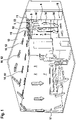
- the figure 1 shows a ventilation device 1, which is installed in a room 2 of a building, not shown.
- the room 2 is a hotel room 3 of a hotel.
- the hotel room 3 has a corridor area 5 starting from the room door 4, from which it leads via a door 6 to a windowless bathroom.
- the corridor area 5 opens into a lounge area 7 of the hotel room 3, in which there is a bed and other furnishings, for example.
- the corridor area 5 is provided with a suspended ceiling 8, the ventilation device 1 being housed in this suspended area. Due to the windowless bathroom, the corridor area 5 has a limited width B, that is, only the width B is available as an installation width for the ventilation device 1.
- the ventilation device 1 has an air inlet 9 which is arranged on the suspended ceiling 8 . Furthermore, the ventilation device 1 has an air outlet 10 which is arranged in the vertical area of a step 11 with which the suspended ceiling 8 merges into the unsuspended ceiling 12 of the living area 7 .
- the ventilation device 1 which is designed as a ceiling installation device 13, sucks in room air 14 through the air inlet 9 and then conditions the room air 14 by means of a heat exchanger 15 ( figure 2 ) and mixes the conditioned room air 14 with primary air and then ejects the mixed air 16 thus formed as supply air 52 from the air outlet 10, with the mixed air 16 or supply air 52 then sweeping along the ceiling 12 of the lounge area 7 until it reaches the facade 17 of the hotel room 3 is reached and sinks down there, becomes room air 14 and flows back over the floor area 18 of the occupied zone 7 in the direction of the corridor area 5, where it rises and is sucked in again by the air inlet 5. In this way, an air roll is established, which serves to ventilate and/or air-condition the hotel room 3 .
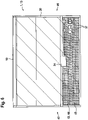
- the figure 2 shows a longitudinal section through the ventilation device 1.
- the ventilation device 1 has a housing 20 which has a housing length GL ( figure 2 ) and - according to figure 3 - a housing width GB.
- the air outlet 10 extends slightly beyond the housing length GL.
- the air outlet 10 has air guiding slats 21 in order to be able to guide the exiting mixed air 16 (supply air 52) within a certain angle.
- the influencing of the air outlet direction by means of the air guide slats 21 is not considered. Rather, only the air outlet direction 19 is used to determine the direction, that is, the mixed air 16 exits in the horizontal direction from the opening of the air outlet 10 running in the vertical direction in the air outlet direction 19 .
- the air outlet 10 is located on an end face 22 of the housing 20 .
- the air distribution box 25 is located inside the housing 20 opposite the air outlet 10.
- the housing 20 has the horizontally arranged heat exchanger 15, which has a plurality of mutually parallel heat exchanger fins 29, of which in FIG figure 2 only a small zone is marked.
- the heat exchanger fins 29 are arranged in parallel over the entire length WL of the heat exchanger 15 and leaving air flow gaps free, i.e. this parallel arrangement extends over the entire length WL, with two adjacent heat exchanger fins 29 forming an air flow gap between them.
- a large number of heat exchanger fins 29 are arranged one behind the other over the housing length GL or the heat exchanger length WL or in the direction of the air outlet direction 19, leaving air flow gaps free in each case.
- the heat exchanger fins 29 are threaded onto heat exchange tubes 30 and connected to them in a thermally conductive manner.
- the heat exchange tubes 30 run meandering, where - according to figure 3 - Two layers 31 and 32 and also deflection bends 33 between the layers 31 and 32 are provided. According to figure 4 it can be seen that the heat exchange tubes 30 have heat exchange sections 34 that run in a straight line and deflection sections 35 in order to arrive at the meandering course, wherein in FIG figure 4 the meandering course is indicated with an arrow 36 for clarification.
- the heat exchanger fins 29 can be seen, which are arranged in packets, and are penetrated by the heat exchange tubes 30, where - just as in the figure 2 - in the figure 4 also only a narrow zone is distinguished, which represents the air guide slats 21 in detail. In the remaining area, it is indicated only schematically that heat exchanger fins 29 are also located there.
- the heat exchange tubes 30 of the heat exchanger 15 are connected to medium connection pieces 37 designed without bends, one of the medium connection pieces 37 having a valve drive 38 with a valve.
- the medium connection pieces 37 run in a straight line, with one serving as an inlet for a medium and the other serving as an outlet.
- the medium is a heating medium or a coolant, in particular water is used, ie warm water or cold water, to heat or cool air that passes through the heat exchanger 15 .
- the heat exchanger fins 29 extend almost over the entire housing width GB.
- the heat exchanger fins 29 have a fin length LL which is only slightly smaller than the housing width GB of the housing 20.
- - according to figure 4 Run the heat exchanger fins 29 transversely, namely at right angles to the air outlet direction 19 of the air outlet 10.
- the heat exchange tubes 30 run with their heat exchange sections 34 in the direction of the air outlet direction 19 of the air outlet 10 .
- the deflection section 35 protruding from the fin pack of the heat exchanger fins 29 are in the area of the front end 39 and in the area of the rear end 40 of the ventilation device 1, i.e. not on its sides 41 and 42 ( figure 4 ). Because of this design, it is possible that the width B of the corridor area 5 ( figure 1 ) can be used almost completely by the heat exchanger fins 29, that is, the heat exchanger fins 29 extend almost over the entire width B. Despite this small width B, a very large heat exchange surface of the heat exchanger 15 is therefore available.
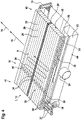
- the air inlet 9, which is arranged on the underside of the ventilation device 1, is provided with a removable, air-permeable air inlet cover 43.
- This is designed in particular as an air inlet grille 44 .
- the air inlet cover 43 essentially has the dimensions of the base area of the housing 20, but extends beyond the housing 20 at the rear end 40, so that both the primary air connection piece 24 and the medium connection piece 37 are overlapped. When installed, this means that when the air inlet cover 43 is removed, an inspection opening 45 is released, which not only allows access to the heat exchanger 15, but also to the primary air connection piece 24 and the medium connection piece 37 and also to the valve drive 39 with valve located there.
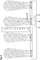
- the top view of the ventilation device 1 according to figure 6 shows the size of the inspection opening 45, which corresponds to the base area of the air inlet cover 43 and is shown hatched.
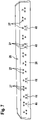
- the air distribution box 25 is equipped with primary air nozzles 27 on its wall 26 .
- the primary air nozzles 27 are arranged in groups, with three primary air nozzles 27 lying in the corners of an imaginary triangle forming a group 46.
- a total of thirteen groups 46 are provided over the length of the air distribution box 25, this number--depending on the exemplary embodiment--can vary.
- the number of primary air nozzles 27 belonging to a group 46 can also vary in size.
- the triangular arrangement of the primary air nozzles 27 of adjacent groups 46 varies mutually, that is, once the triangle is on the apex and once on a base.
- the arrangement is such that air jets 47 emerging from the primary air nozzles 27 of each group 46 merge into just a single induction air jet 48 .
- the number of induction air jets formed 48 corresponds to the number of groups 46.
- the proportions in the figure 8 are illustrated by a superimposed scale. It can be seen that the group 46 designated there with three primary air nozzles 27 emits three air jets 47 which combine to form a common induction air jet 48 after just a few centimetres.
- the solution in which several small induction nozzles 27 are combined into a group 46 has the following advantages over a (fictitious) large nozzle:
- the sum of the flow noise of the several small primary air nozzles 27 lower than the flow noise of the large nozzle. Accordingly, this also applies to several groups of small primary air nozzles 27 compared to a corresponding number of large primary air nozzles.
- large nozzles are generally preferable because they can induce more secondary air over a corresponding device width and therefore achieve a greater cooling or heating capacity.
- the merging of the air jets 47 of the individual primary air nozzles 27 of each group 46 produces a common induction air jet 48, which also has a large induction effect
- the arrangement results in correspondingly positive, equivalent induction effects.
- the air jets 47 initially acting as free jets are therefore merged into the respective induction air jet 48, with the effect of this combined induction air jet 48 then corresponding to the effect of a jet of a fictitious large induction nozzle or primary air nozzle.
- the individual primary air nozzles 27 have a distance of around 20 mm, in particular 18 mm, from one another. After a free jet length of 20 to 30 mm of the individual air jets 47, they combine to form the common induction air jet 48.
- the ventilation device 1 results in the following function: It is assumed that a ventilation device 1 according to the invention in a room 2, in particular a hotel room 3 according to figure 1 , is installed.
- the primary air connection piece 24 is connected to a primary air line of an air distribution network of the building and the medium connection pieces 37 of the heat exchanger 15 are connected to corresponding medium inlet and outlet lines, in particular a cold or hot water circuit.
- Due to the primary air 50 introduced into the air distribution box 25 the combining air jets 47 emerging from the primary air nozzles 27 produce an induction effect, as a result of which room air 14 is sucked in through the air inlet 9 .
- the room air 14 passes through the heat exchanger 15 and is heat-treated accordingly.
- the air treated in this way enters a mixing chamber 51 in front of the primary air nozzles 27 and mixes there with the primary air 50 emerging from the primary air nozzles 27 to form mixed air 16.
- the mixed air 16 emerges from the air outlet 10 in the air outlet direction 19 as supply air 52, resulting in the air roll, just like them to the figure 1 was described.
- the heat exchanger fins 29 extend essentially over the entire housing width GB of the ventilation device 1 and this housing width GB corresponds approximately to the width B of the corridor area 5 of the room 2, a high level of efficiency in terms of heating or cooling capacity is achieved despite this limited dimension, so that a very pleasant room air situation is created in room 2, in addition due to the grouping of the primary air nozzles 27 there is no acoustic nuisance and despite the lack of an electric air conveyor, such as for Example of a tangential fan, a high circulation rate can be achieved without causing drafts in the occupied area 7 .
- an optional condensate pan 53 indicated with a dashed line.
- the aspirated room air 14 then flows into the area between the condensate pan 53 and the heat exchanger 15 and from there through the heat exchanger 15 .
- the air inlet 9 is preferably at least partially in front of the condensate pan 53 (viewed in the air outlet direction 19).
Landscapes
- Engineering & Computer Science (AREA)
- Chemical & Material Sciences (AREA)
- Combustion & Propulsion (AREA)
- Mechanical Engineering (AREA)
- General Engineering & Computer Science (AREA)
- Air Filters, Heat-Exchange Apparatuses, And Housings Of Air-Conditioning Units (AREA)
- Central Air Conditioning (AREA)
- Ventilation (AREA)
Description
- Die Erfindung betrifft ein lufttechnisches Gerät zur Belüftung und/oder Klimatisierung eines Raumes eines Gebäudes, insbesondere eines Hotelzimmers eines Hotels, mit mindestens einem, Wärmetauscherlamellen aufweisenden Wärmetauscher, mindestens einem Lufteinlass für Raumluft und mindestens einem Luftauslass für den in den Raum eintretende Zuluft.
- Ein lufttechnisches Gerät gemäß dem Oberbegriff von Anspruch 1 ist aus Dokument
EP 1 130 331 bekannt. - Es wird insbesondere in Hotelzimmern eingesetzt, die zumeist einen Standardzuschnitt haben, das heißt, angrenzend an die Tür des Hotelzimmers folgt ein kurzer Flurbereich mit abgehängter Decke und Zugang zu einem fensterlosen Bad. Der Flur mündet in einen Aufenthaltsbereich, in dem sich ein Bett und eine Sitzgelegenheit befinden. Der Aufenthaltsbereich besitzt keine abgehängte Decke, sodass zum Flur hin eine Stufe besteht, die genutzt wird, um dort das vorstehenden genannte, bekannte lufttechnische Gerät zur Belüftung und/oder Klimatisierung unterzubringen. Das bekannte lufttechnische Gerät ist als sogenanntes "Fancoil-Gerät" ausgebildet, das heißt, es besitzt einen mit Wärmetauscherlamellen versehenen Wärmetauscher, einen Lufteinlass und einen Luftauslass sowie einen Querstromventilator. Der Querstromventilator fördert Raumluft, die in den Lufteinlass eintritt, den Wärmetauscher durchsetzt und hierdurch konditioniert wird. Die konditionierte Luft wird durch den Luftauslass in den Raum eingebracht. Da sich - wie vorstehend beschrieben - das lufttechnische Gerät in der Decke des Flurbereichs des Hotelzimmers befindet, ist die zur Verfügung stehende Breite vorgegeben, da das Gerät maximal ein Breitenmaß besitzen kann, das der Breite des Flures entspricht. Im abgehängten Deckenbereich befindet sich der Lufteinlass und der Luftauslass ist an der vertikalen Stirnseite der durch die abgehängte Decke des Flures zum Aufenthaltsbereich hin gebildeten Stufe angeordnet. Das bekannte lufttechnische Gerät ist aufgrund seines Aufbaus relativ teuer und verursacht ferner nicht unerhebliche Betriebskosten.
- Der Erfindung liegt daher die Aufgabe zugrunde, ein lufttechnisches Gerät der eingangs genannten Art zur Verfügung zu stellen, das der speziellen Einbausituation, insbesondere im Hotelzimmerbereich, gerecht wird, dennoch einen hohen Wirkungsgrad und damit ein sehr gutes Belüftungs- und/oder Klimatisierungsergebnis erbringt und insbesondere gleichzeitig kostengünstig in der Herstellung und auch im Betrieb ist.
- Diese Aufgabe wird erfindungsgemäß durch die Merkmale des Anspruchs 1 gelöst. Im Gegensatz zum bisher bekannten Gerät arbeitet das erfindungsgemäße Gerät nach dem Induktionsprinzip, das heißt, nicht ein mit einem elektrischen Antrieb versehener Querstromventilator ist erforderlich, um Raumluft anzusaugen, durch den Wärmetauscher zu führen und aus dem Luftauslass wieder in den Raum einzubringen, sondern das erfindungsgemäße lufttechnische Gerät ist an ein Luftverteilungsnetz, insbesondere Primärluftverteilungsnetz, des Gebäudes, Hotels oder dergleichen angeschlossen. In einer für das gesamte Gebäude zuständigen Luftzentrale wird Primärluft aufbereitet und über das Kanalnetz dem Raum, insbesondere Hotelzimmer, zugeführt. Diese Primärluft tritt in eine Induktionseinrichtung des erfindungsgemäßen lufttechnischen Geräts ein und erzeugt eine Induktionswirkung die dazu führt, dass Raumluft durch den Lufteinlass angesaugt und durch den Wärmetauscher geführt wird. Anschließend wird die Primärluft mit der nunmehr konditionierten Raumluft gemischt und diese Mischluft tritt dann durch den Luftauslass als Zuluft in den Raum ein. Auf diese Art und Weise gelangt stets auch ein Frischluftanteil aufgrund der Primärluft in den Raum. Da die Kühl- oder Heizleistung eines Induktionsgeräts bei vergleichbaren Parametern grundsätzlich geringer ist, als bei einem entsprechenden Gerät, das als Fancoil ausgebildet ist, ist bei der Erfindung vorgesehen, den Wärmetauscher derart anzuordnen, dass seine Wärmetauscherlamellen quer, insbesondere rechtwinklig oder nahezu rechtwinklig zur Luftaustrittsrichtung des Luftauslasses verlaufen. Während also bei dem bekannten, als Fancoil ausgebildeten Gerät die Luft in den Lufteinlass mittels des Querstromventilators eingesaugt wird und dann zwischen den Wärmetauschlamellen hindurch in Richtung auf den Luftauslass strömt, wobei sich in dieselbe Richtung die Wärmetauscherlamellen erstrecken, ist bei der erfindungsgemäßen Anordnung vorgesehen, dass sich die Wärmetauscherlamellen quer dazu erstrecken, also um 90° verdreht zur Ausführungsform des Standes der Technik liegen. Dieses erfindungsgemäße Vorgehen hat den Vorteil, dass sich die Wärmetauscherlamellen über die gesamte oder nahezu die gesamte Breite des lufttechnischen Geräts erstrecken können. Dies ist möglich, weil der Wärmetauscher mit Wärmetauschrohren bestückt ist, also Rohre, in denen ein Medium zum Heizen oder Kühlen geführt wird, vorzugsweise warmes oder kaltes Wasser, die meandernd verlaufen, sodass sie Wärmetauschabschnitte aufweisen, die mit den Wärmetauscherlamellen wärmeleitfähig verbunden sind und um Umlenkabschnitte, um den meandernden Verlauf zu erzielen. Während nun im Stand der Technik sich die Wärmetauscherlamellen in Luftaustrittsrichtung des Luftauslasses erstrecken und die Wärmetauschabschnitte quer dazu, das heißt, zwischen den Wärmetauscherlamellen und den Wärmetauschabschnitten besteht ein 90° Winkel, ist bei der Erfindung vorgesehen, dass die Wärmetauscherlamellen quer zur Luftaustrittsrichtung des Luftauslasses verlaufen und die Wärmetauschabschnitte quer, insbesondere 90° dazu, dass sich letztere also in Luftaustrittsrichtung des Luftauslasses erstrecken. Damit liegen bei dem bekannten lufttechnischen Gerät die Umlenkabschnitte der Wärmetauschrohre an den Geräteseiten, sodass die Gerätebreite nicht vollständig von den Wärmetauscherlamellen genutzt werden können. Beim erfindungsgemäßen Gerät hingegen liegen die Umlenkabschnitte im vorderen und hinteren Bereich der Längserstreckung des Geräts, also nicht an den Seiten, sodass dort die volle Breite für die Erstreckung der Wärmetauscherlamellen zur Verfügung steht. Die Folge ist, dass ein entsprechend besserer Wirkungsgrad des Wärmetauschers beim Gegenstand der Erfindung erzielt wird als beim Gegenstand des bekannten Geräts, sodass die vergleichbar geringere Förderleistung durch das Induktionsprinzip beim erfindungsgemäßen Gerät ausgeglichen oder etwa ausgeglichen wird gegenüber der Förderleistung des Querstromventilators. Ferner erfordert das erfindungsgemäße lufttechnische Gerät keinen Ventilator beziehungsweise Querstromventilator und somit auch keinen elektrischen Antrieb. Damit vereinfacht sich der Aufbau des Geräts und wird entsprechend preiswerter und führt auch zu geringeren Betriebskosten.
- Nach einer Weiterbildung der Erfindung ist vorgesehen, dass der Wärmetauscher vorzugsweise krümmerfreie Mediumanschlussstutzen, insbesondere Wasseranschlussstutzen, aufweist, die in der Luftaustrittsrichtung oder im Wesentlichen in der Luftaustrittsrichtung des Luftauslasses verlaufen. Die Mediumanschlussstutzen dienen dem Anschluss der Wärmetauschrohre an Zu- und Abführleitungen, um das Heizmedium beziehungsweise Kühlmedium, also insbesondere warmes oder kaltes Wasser zu- und abzuführen. Während beim erwähnten bekannten Gerät seitlich neben dem Wärmetauscher als Krümmer ausgebildete Mediumanschlussstutzen liegen, die insbesondere auch noch einen Ventilantrieb mit Ventil aufweisen, ist bei der Ausgestaltung vorgesehen, dass die Mediumanschlussstutzen krümmerfrei, also gerade verlaufend ausgebildet sind, und nicht seitlich neben dem Wärmetauscher liegen, sondern - in Luftaustrittsrichtung des Luftauslasses gesehen - vor dem Wärmetauscher, also wird ein Raum in Längserstreckung des lufttechnischen Geräts genutzt, um dort die erwähnten Teile unterzubringen, was die zu nutzende Breite des Wärmetauschers nicht einschränkt. Beim erfindungsgemäßen Gerät kann selbstverständlich auch ein Ventilantrieb mit Ventil vorgesehen sein, der jedoch auch nicht im Hinblick auf die vorstehend erwähnten Raumverhältnisse störend in Erscheinung tritt.
- Nach einer Weiterbildung der Erfindung ist bei dem lufttechnischen Gerät ein Gehäuse vorgesehen, das eine Gehäuselänge und eine Gehäusebreite aufweist, wobei sich die Gehäuselänge in Luftaustrittsrichtung des Luftauslasses erstreckt und sich die Wärmetauscherlamellen über die gesamte oder nahezu die gesamte Gehäusebreite erstrecken. Die gesamte Gehäusebreite dient daher der Aufnahme der Wärmetauscherlamellen, die sich über diese Gehäusebreite erstrecken, während sich quer dazu, insbesondere 90° dazu, die Gehäuselänge erstreckt, über die der Wärmetauscher mit in gleicher Richtung verlaufenden Wärmetauschabschnitten der Wärmetauschrohre angeordnet ist und in derselben Richtung auch die Mediumanschlussstutzen geradlinig verlaufen, wobei die Mediumanschlussstutzen - in Luftaustrittsrichtung des Luftauslasses gesehen - vor dem Wärmetauscher liegen.
- Das Induktionsgerät weist mindestens einen Primärluftanschlussstutzen für die Zuführung von Primärluft auf. Der Primärluftanschlussstutzen ist vorzugsweise mit einem Primärluftkanal des vorstehend erwähnten Luftverteilungsnetzes verbunden, das heißt, die Luftzentrale liefert Primärluft, die über das Kanalnetz bis zum Primärluftanschlussstutzen geführt wird. Von dort tritt die Primärluft zur Erzeugung einer Induktionswirkung in das lufttechnische Gerät ein. Bevorzugt ist vorgesehen, dass der Primärluftanschlussstutzen krümmerfrei, also geradlinig, ausgebildet ist und erfindungsgemäß in oder im Wesentlichen in Luftaustrittsrichtung des Luftauslasses verläuft, sich also über die Gerätelänge beziehungsweise Gehäuselänge des erfindungsgemäßen lufttechnischen Geräts erstreckt und somit ebenfalls keinen Bauraum in den Seitenbereichen benötigt.
- Gemäß der Erfindung ist vorgesehen, dass der Primärluftanschlussstutzen in einen Luftverteilkasten mündet, an dem Induktionsdüsen bildende Primärluftdüsen angeschlossen, insbesondere angeschlossen und befestigt oder insbesondere angeschlossen und ausgebildet sind. Primärluftanschlussstutzen, Luftverteilkasten und Induktionsdüsen bilden insgesamt die bereits erwähnte Induktionseinrichtung. "Angeschlossen" bedeutet vorstehend, dass die Induktionsdüsen lufttechnisch mit dem Luftverteilkasten verbunden sind. "Geschlossen und befestigt" bedeutet, dass der lufttechnische Anschluss der Induktionsdüsen zum Luftverteilkasten besteht und dass der Luftverteilkasten die Induktionsdüsen trägt, das heißt, die separaten Induktionsdüsen werden am Luftverteilkasten befestigt. "Angeschlossen und ausgebildet" bedeutet, dass die Induktionsdüsen lufttechnisch mit dem Luftverteilkasten verbunden sind und dass die Induktionsdüsen am Luftverteilkasten ausgebildet, also einstückig mit dem Luftverteilkasten erstellt sind.
- Eine Weiterbildung der Erfindung sieht vor, dass der Lufteinlass eine Lufteinlassöffnung aufweist, die zumindest bereichsweise eine Revisionsöffnung für das Induktionsgerät bildet. Die Lufteinlassöffnung dient also gleichzeitig als Zugangsöffnung, um zu den einzelnen Baugruppen des lufttechnischen Geräts Zugang zu erhalten, beispielsweise um eine Revision durchzuführen. Anders als im Stand der Technik, bei dem neben der Lufteinlassöffnung eine separate Revisionsöffnung mit Abdeckung vorgesehen ist, ergeben sich somit Material- und Kosteneinsparungen aufgrund der Ausbildung. Insbesondere ist vorgesehen, dass der Lufteinlass eine demontierbare, luftdurchlässige Lufteinlassabdeckung, insbesondere ein Luftgitter, aufweist, die/das sich auf der dem Luftauslass gegenüberliegenden Seite des Gehäuses hinaus, insbesondere zur Ausbildung der Revisionsöffnung überdas Gehäuse hinaus erstreckt. Demzufolge dient die luftdurchlässige Lufteinlassabdeckung gleichzeitig zum Verschluss der Revisionsöffnung, das heißt, die Revisionsöffnung oder zumindest ein Anteil von ihr dient gleichzeitig als Lufteinlass. Grundsätzlich würde es für den Einlass der Raumluft in das lufttechnische Gerät ausreichen, wenn sich der Lufteinlass im Bereich des Gehäuses des lufttechnischen Geräts befindet, sodass die eintretende Luft zum Wärmetauscher gelangt. Wie vorstehend erwähnt, ist vorgesehen, dass sich die luftdurchlässige Lufteinlassabdeckung über das Gehäuse hinaus - in Längserstreckung des Gehäuses - erstreckt und insofern bei Demontage auch Zugang zu einer hinteren Stirnseite des lufttechnischen Geräts bietet und somit einen Zugang insbesondere zu dem Primärluftanschlussstutzen und/oder den Mediumanschlussstutzen und/oder dem Ventilantrieb mit Ventil bietet.
- Das Induktionsgerät ist als Deckeneinbaugerät ausgebildet. Dies ist in der vorstehend beschriebenen Hotelzimmersituation bevorzugt der Fall.
- Nach einer Weiterbildung der Erfindung ist vorgesehen, dass die Primärluftdüsen gruppiert, insbesondere räumlich gruppiert, derart ausgebildet und/oder angeordnet sind, dass die aus den Primärluftdüsen einer jeden der Gruppen austretenden Luftstrahlen zu nur einem Induktionsluftstrahl verschmelzen. Mithin sind keine im Querschnitt großen Primärluftdüsen, sondern vorzugsweise jeweils mehrere im Querschnitt kleinere Primärluftdüsen derart gruppiert, insbesondere räumlich gruppiert, dass die dort austretenden Luftstrahlen in geringem Abstand zu den Austrittsöffnungen der Primärluftdüsen, insbesondere schon auf wenigen Zentimetern, miteinander zu nur einem einzigen Induktionsluftstrahl verschmelzen. Dies hat den Vorteil, dass gute akustische Werte erzielt werden und dennoch eine sehr gute Induktionswirkung.
- Nach einer Weiterbildung der Erfindung ist vorgesehen, dass die Gruppen als Zweier- bis Fünfergruppen (also mit zwei Primärluftdüsen pro Gruppe bis zu fünf Primärluftdüsen pro Gruppe), insbesondere Dreiergruppen mit jeweils drei Primärluftdüsen, ausgebildet sind. Somit sind bevorzugt jeweils drei Primärluftdüsen gruppenmäßig zusammengefasst, wobei deren austretende Luftstrahlen einen gemeinsamen Induktionsluftstrahl bilden. Über die gesamte Breite des lufttechnischen Geräts sind eine bestimmte Anzahl von Gruppen angeordnet, beispielsweise drei Gruppen bis zwanzig Gruppen.
- Schließlich ist vorteilhaft, dass für ein dauerhaftes oder längerfristiges Betreiben des Induktionsgeräts im kondensierenden Betrieb eine Kondensatwanne vorgesehen ist. Bei diesem erfindungsgemäßen Vorgehen wird also das lufttechnische Gerät so betrieben, dass es zur Kondensation kommt, beispielsweise schlägt sich die Feuchtigkeit der Raumluft am Wärmetauscher nieder, sodass Kondensat ausfällt, das jedoch von der Kondensatwanne aufgefangen wird und daher nicht störend in Erscheinung tritt. Derartige lufttechnische Geräte, die als Induktionsgeräte ausgebildet sind, werden üblicherweise nicht dauerhaft oder längerfristig in einem derartigen Betrieb betrieben. Vielmehr weisen derartige Induktionsgeräte zwar gegebenenfalls eine Kondensatwanne auf, diese dient jedoch nur für das Auffangen von ungewollt im grundsätzlich nicht kondensierenden Betrieb ausfallendem Kondensat. Sie ist nicht dafür vorgesehen, das Induktionsgerät - so wie bei dem Gegenstand der Erfindung - längerfristig oder auch dauerhaft im kondensierenden Betrieb zu betreiben.
- Die Zeichnungen veranschaulichen die Erfindung anhand eines Ausführungsbeispiels, und zwar zeigt:
- Figur 1
- ein Hotelzimmer mit eingebautem lufttechnischen Gerät,
- Figur 2
- einen Längsschnitt durch das lufttechnische Gerät,
- Figur 3
- eine Rückansicht auf das lufttechnische Gerät,
- Figur 4
- eine perspektivische Ansicht auf das lufttechnische Gerät im Wesentlichen von unten sowie von hinten,
- Figur 5
- eine perspektivische Ansicht des lufttechnischen Geräts in Einbaulage im Wesentlichen von der Seite sowie von hinten,
- Figur 6
- eine Draufsicht auf das lufttechnische Gerät,
- Figur 7
- eine perspektivische Ansicht auf eine Induktionseinrichtung des lufttechnischen Geräts, und
- Figur 8
- ein Strömungsbild von Induktionsdüsen der Induktionseinrichtung.
- Die
Figur 1 zeigt ein lufttechnisches Gerät 1, das in einen Raum 2 eines nicht näher dargestellten Gebäudes eingebaut ist. Bei dem Raum 2 handelt es sich um ein Hotelzimmer 3 eines Hotels. - Das Hotelzimmer 3 weist einen von der Zimmertür 4 ausgehenden Flurbereich 5 auf, von dem es über eine Tür 6 zu einem fensterlosen Bad führt. Der Flurbereich 5 mündet in einen Aufenthaltsbereich 7 des Hotelzimmers 3, in der sich beispielsweise ein Bett und andere Einrichtungsgegenstände befinden. Der Flurbereich 5 ist mit einer abgehängten Decke 8 versehen, wobei in diesem abgehängten Bereich das lufttechnische Gerät 1 untergebracht ist. Aufgrund des fensterlosen Bads weist der Flurbereich 5 eine eingeschränkte Breite B auf, das heißt, nur die Breite B steht als Einbaubreite für das lufttechnische Gerät 1 zur Verfügung.
- Gemäß
Figur 1 weist das lufttechnische Gerät 1 einen Lufteinlass 9 auf, der an der abgehängten Decke 8 angeordnet ist. Ferner besitzt das lufttechnische Gerät 1 einen Luftauslass 10, der im vertikalen Bereich einer Stufe 11 angeordnet ist, mit der die abgehängte Decke 8 in die nicht abgehängte Zimmerdecke 12 des Aufenthaltsbereichs 7 übergeht. - Im Betrieb saugt das lufttechnische Gerät 1, das als Deckeneinbaugerät 13 ausgebildet ist, Raumluft 14 durch den Lufteinlass 9 an, konditioniert dann die Raumluft 14 mittels eines Wärmetauschers 15 (
Figur 2 ) und mischt die konditionierte Raumluft 14 mit Primärluft und stößt dann die so gebildete Mischluft 16 als Zuluft 52 aus dem Luftauslass 10 aus, wobei die Mischluft 16 beziehungsweise Zuluft 52 dann an der Decke 12 des Aufenthaltsbereichs 7 entlangstreicht, bis sie die Fassade 17 des Hotelzimmers 3 erreicht und dort herabsinkt, zur Raumluft 14 wird und über den Bodenbereich 18 der Aufenthaltszone 7 zurück in Richtung Flurbereich 5 strömt, dort aufsteigt und wieder vom Lufteinlass 5 angesaugt wird. Auf diese Art und Weise stellt sich eine Luftwalze ein, die der Belüftung und/oder Klimatisierung des Hotelzimmers 3 dient. - Die
Figur 2 zeigt einen Längsschnitt durch das lufttechnische Gerät 1. Ein Vergleich mit derFigur 1 zeigt, dass der Längsschnitt in Richtung der Luftaustrittsrichtung 19 des Luftauslasses 10 verläuft. Das lufttechnische Gerät 1 weist ein Gehäuse 20 auf, das eine Gehäuselänge GL besitzt (Figur 2 ) und - gemäßFigur 3 - eine Gehäusebreite GB. DerFigur 2 ist zu entnehmen, dass sich der Luftauslass 10 geringfügig über die Gehäuselänge GL hinaus erstreckt. Ferner weist der Luftauslass 10 Luftleitlamellen 21 auf, um die austretende Mischluft 16 (Zuluft 52) innerhalb eines gewissen Winkels lenken zu können. Im Zuge dieser gesamten Anmeldung wird jedoch die Beeinflussung der Luftaustrittsrichtung mittels der Luftleitlamellen 21 nicht betrachtet. Vielmehr wird nur die Luftaustrittsrichtung 19 zur Richtungsbestimmung herangezogen, das heißt, die Mischluft 16 tritt in horizontaler Richtung aus der in vertikaler Richtung verlaufenden Öffnung des Luftauslasses 10 in Luftaustrittsrichtung 19 aus. - Der Luftauslass 10 befindet sich an einer Stirnseite 22 des Gehäuses 20. An einer der Stirnseite 22 gegenüberliegenden Rückseite 23 des Gehäuses 20 befindet sich ein Primärluftanschlussstutzen 24, der in das Innere eines Luftverteilkastens 25 des lufttechnischen Geräts 1 führt. Der Luftverteilkasten 25 befindet sich im Innern des Gehäuses 20 in Gegenüberlage zum Luftauslass 10. An einer dem Primärluftanschlussstutzen 24 gegenüberliegenden Wand 26 weist der Luftverteilkasten 25 Primärluftdüsen 27 (auch "Induktionsdüsen" genannt) auf, die in Richtung auf den Luftauslass 10 ausgerichtet sind. Im unteren Bereich 28 weist das Gehäuse 20 den liegend angeordneten Wärmetauscher 15 auf, der eine Vielzahl von parallel zueinander verlaufenden Wärmetauscherlamellen 29 besitzt, von denen in der
Figur 2 nur eine kleine Zone ausgezeichnet ist. Die Wärmetauscherlamellen 29 sind jedoch in Parallelanordnung über die gesamte Länge WL des Wärmetauschers 15 und unter Freilassung von Luftdurchströmungsspalten angeordnet, das heißt, diese Parallelanordnung erstreckt sich über die gesamte Länge WL, wobei jeweils zwei benachbart zueinander liegende Wärmetauscherlamellen 29 zwischen sich einen Luftdurchströmungsspalt ausbilden. Insofern schließen sich über die Gehäuselänge GL beziehungsweise die Wärmetauscherlänge WL beziehungsweise in Richtung der Luftaustrittsrichtung 19 eine Vielzahl von Wärmetauscherlamellen 29 in Hintereinanderanordnung unter jeweils Freilassung von Luftdurchströmungsspalten aneinander an. Die Wärmetauscherlamellen 29 sind auf Wärmetauschrohre 30 aufgefädelt und mit diesen wärmeleitfähig verbunden. Die Wärmetauschrohre 30 verlaufen meanderförmig, wobei - gemäßFigur 3 - zwei Lagen 31 und 32 und auch Umlenkbögen 33 zwischen den Lagen 31 und 32 vorgesehen sind. GemäßFigur 4 ist erkennbar, dass die Wärmetauschrohre 30 Wärmetauschabschnitte 34 besitzen, die geradlinig verlaufen und Umlenkabschnitte 35, um zu dem meandernden Verlauf zu gelangen, wobei in derFigur 4 mit einem Pfeil 36 der meandernde Verlauf zur Verdeutlichung angedeutet ist. DerFigur 4 sind ferner die Wärmetauscherlamellen 29 zu entnehmen, die paketförmig angeordnet sind, und von den Wärmetauschrohren 30 durchsetzt werden, wobei - ebenso wie in derFigur 2 - in derFigur 4 ebenfalls nur noch eine schmale Zone ausgezeichnet ist, die die Luftleitlamellen 21 im Einzelnen darstellt. Im übrigen Bereich ist lediglich schematisch angedeutet, dass sich dort auch Wärmetauscherlamellen 29 befinden. - Aus den
Figuren 2 bis 4 , insbesondere 4, ist ersichtlich, dass die Wärmetauschrohre 30 des Wärmetauschers 15 an krümmerfrei ausgebildete Mediumanschlussstutzen 37 angeschlossen sind, wobei einer der Mediumanschlussstutzen 37 einen Ventilantrieb 38 mit Ventil aufweist. Die Mediumanschlussstutzen 37 verlaufen geradlinig, wobei der eine als Zulauf für ein Medium und der andere als Ablauf dient. Bei dem Medium handelt es sich um ein Heizmittel oder ein Kühlmittel, insbesondere kommt Wasser zum Einsatz, also warmes Wasser oder kaltes Wasser, um Luft, die den Wärmetauscher 15 durchsetzt, zu erwärmen oder zu kühlen. - Gemäß der Figuren insbesondere 2 bis 4, ist erkennbar, dass sich die Wärmetauscherlamellen 29 fast über die gesamte Gehäusebreite GB erstrecken. Gemäß
Figur 3 weisen die Wärmetauscherlamellen 29 eine Lamellenlänge LL auf, die nur geringfügig kleiner ist als die Gehäusebreite GB des Gehäuses 20. Ferner ist erkennbar, dass - gemäßFigur 4 - die Wärmetauscherlamellen 29 quer, nämlich rechtwinklig, zur Luftaustrittsrichtung 19 des Luftauslasses 10 verlaufen. Insbesondere ist auch derFigur 4 zu entnehmen, dass die Wärmetauschrohre 30 mit ihren Wärmetauschabschnitten 34 in Richtung der Luftaustrittsrichtung 19 des Luftauslasses 10 verlaufen. Die aus dem Lamellenpaket der Wärmetauscherlamellen 29 herausragenden Umlenkabschnitt 35 liegen im Bereich des vorderen Endes 39 und im Bereich des hinteren Endes 40 des lufttechnischen Geräts 1, also nicht an dessen Seiten 41 und 42 (Figur 4 ). Aufgrund dieser Ausgestaltung ist es möglich, dass die Breite B des Flurbereichs 5 (Figur 1 ) fast vollständig von den Wärmetauscherlamellen 29 genutzt werden kann, das heißt die Wärmetauscherlamellen 29 erstrecken sich fast über die gesamte Breite B. Trotz dieser geringen Breite B steht daher eine sehr große Wärmetauschfläche des Wärmetauschers 15 zur Verfügung. - Der
Figur 5 ist zu entnehmen, dass der Lufteinlass 9, der an der Unterseite des lufttechnischen Geräts 1 angeordnet ist, mit einer demontierbaren, luftdurchlässigen Lufteinlassabdeckung 43 versehen ist. Diese ist insbesondere als Lufteinlassgitter 44 ausgebildet. Die Lufteinlassabdeckung 43 weist im Wesentlichen die Größenabmessungen der Grundfläche des Gehäuses 20 auf, erstreckt sich jedoch am hinteren Ende 40 über das Gehäuse 20 hinaus, sodass sowohl der Primärluftanschlussstutzen 24 als auch die Mediumanschlussstutzen 37 überlappt werden. Im eingebauten Zustand hat dies zur Folge, dass bei demontierter Lufteinlassabdeckung 43 eine Revisionsöffnung 45 freigegeben wird, die nicht nur Zugang zum Wärmetauscher 15 gestattet, sondern auch zu dem Primärluftanschlussstutzen 24 sowie den Mediumanschlussstutzen 37 und auch zum dort befindlichen Ventilantrieb 39 mit Ventil. - Die Draufsicht auf das lufttechnische Gerät 1 gemäß
Figur 6 verdeutlicht die Größe der Revisionsöffnung 45, die der Grundfläche der Lufteinlassabdeckung 43 entspricht und schraffiert verdeutlicht ist. - Der
Figur 2 ist zu entnehmen, dass der Luftverteilkasten 25 an seiner Wand 26 mit Primärluftdüsen 27 ausgestattet ist. GemäßFigur 7 , die eine Draufsicht auf die Wand 26 zeigt, sind die Primärluftdüsen 27 gruppiert angeordnet, wobei jeweils drei in den Ecken eines gedachten Dreiecks liegende Primärluftdüsen 27 eine Gruppe 46 bilden. Insgesamt sind dreizehn Gruppen 46 über die Länge des Luftverteilkastens 25 vorgesehen, wobei diese Anzahl - je nach Ausführungsbeispiel - unterschiedlich sein kann. Auch die Anzahl der Primärluftdüsen 27, die zu einer Gruppe 46 gehören, kann unterschiedlich groß sein. DerFigur 7 ist zu entnehmen, dass die dreieckige Anordnung der Primärluftdüsen 27 benachbarter Gruppen 46 wechselseitig variiert, das heißt, einmal steht das Dreieck auf der Spitze und einmal auf einer Grundfläche. Die Anordnung ist nun so getroffen, dass aus den Primärluftdüsen 27 einer jeden Gruppe 46 austretende Luftstrahlen 47 zu nur einem einzigen Induktionsluftstrahl 48 verschmelzen. Dies ist derFigur 8 sehr anschaulich zu entnehmen. Die Anzahl der gebildeten Induktionsluftstrahlen 48 entspricht der Anzahl der Gruppen 46. Die Größenverhältnisse in derFigur 8 werden durch einen eingeblendeten Maßstab verdeutlicht. Es ist erkennbar, dass die dort bezeichnete Gruppe 46 mit drei Primärluftdüsen 27 drei Luftstrahlen 47 ausstößt, die sich schon nach wenigen Zentimetern zu einem gemeinsamen Induktionsluftstrahl 48 vereinigen. Bei gleichem Gesamtvolumenstrom und mit konstantem, insbesondere gleichem Vordruck weist die Lösung, bei der mehrere kleine Induktionsdüsen 27 zu einer Gruppe 46 vereinigt sind, gegenüber einer (fiktiven) großen Düse folgende Vorteile auf: Hinsichtlich der Akustik ist die Summe des Strömungsrauschens der mehreren kleinen Primärluftdüsen 27 geringer als das Strömungsrauschen der großen Düse. Dies gilt dementsprechend auch bei mehreren Gruppen von kleinen Primärluftdüsen 27 gegenüber einer entsprechenden Anzahl von großen Primärluftdüsen. Hinsichtlich der Induktionswirkung sind grundsätzlich große Düsen vorzuziehen, da sie auf einer entsprechenden Gerätebreite mehr Sekundärluft induzieren können und daher eine größere Kühl- oder Heizleistung erreichen. Da allerdings aufgrund des Verschmelzens der Luftstrahlen 47 der einzelnen Primärluftdüsen 27 jeder Gruppe 46 ein gemeinsamer Induktionsluftstrahl 48 herbeigeführt wird, der ebenfalls eine große Induktionswirkung mit sich bringt, ergeben sich entsprechend positive, gleichwertige Induktionswirkungen bei der Anordnung. Bei der Ausgestaltung werden demnach die anfänglich als Freistrahlen wirkenden Luftstrahlen 47 zu dem jeweiligen Induktionsluftstrahl 48 verschmolzen, wobei die Wirkung dieses vereinigten Induktionsluftstrahls 48 dann der Wirkung eines Strahls einer fiktiven großen Induktionsdüse beziehungsweise Primärluftdüse entspricht. GemäßFigur 8 weisen die einzelnen Primärluftdüsen 27 einen Abstand von rund 20 mm, insbesondere von 18 mm, zueinander auf. Nach einer Freistrahllänge von 20 bis 30 mm der einzelnen Luftstrahlen 47 vereinigen sich diese zu dem gemeinsamen Induktionsluftstrahl 48. - Bei dem erfindungsgemäßen lufttechnischen Gerät 1 ergibt sich folgende Funktion: Es wird davon ausgegangen, dass ein lufttechnisches Gerät 1 gemäß der Erfindung in einem Raum 2, insbesondere ein Hotelzimmer 3 gemäß
Figur 1 , eingebaut ist. Der Primärluftanschlussstutzen 24 ist mit einer Primärluftleitung eines Luftverteilnetzes des Gebäudes verbunden und die Mediumanschlussstutzen 37 des Wärmetauschers 15 sind an entsprechende Mediumzu- und -ableitungen, insbesondere einen Kalt- oder Warmwasserkreislauf, angeschlossen. Durch die in den Luftverteilkasten 25 eingeleitete Primärluft 50 erzeugen die aus den Primärluftdüsen 27 austretenden, sich vereinigenden Luftstrahlen 47 eine Induktionswirkung, wodurch Raumluft 14 durch den Lufteinlass 9 angesaugt wird. Die Raumluft 14 durchsetzt den Wärmetauscher 15 und wird dabei entsprechend wärmebehandelt. Die so behandelte Luft gelangt in einen Mischraum 51 vor den Primärluftdüsen 27 und vermischt sich dort mit der aus den Primärluftdüsen 27 austretenden Primärluft 50 zu Mischluft 16. Die Mischluft 16 tritt in Luftaustrittsrichtung 19 als Zuluft 52 aus dem Luftauslass 10 aus und es ergibt sich die Luftwalze, so wie sie zu derFigur 1 beschrieben wurde. Da sich die Wärmetauscherlamelle 29 im Wesentlichen über die gesamte Gehäusebreite GB des lufttechnischen Geräts 1 erstrecken und diese Gehäusebreite GB etwa der Breite B des Flurbereichs 5 des Raums 2 entspricht, wird trotz dieses begrenzten Maßes ein hoher Wirkungsgrad hinsichtlich einer Heiz- oder Kühlleistung erzielt, sodass eine sehr angenehme Raumluftsituation im Raum 2 geschaffen ist, wobei zusätzlich aufgrund der Gruppierung der Primärluftdüsen 27 keine akustische Belästigung besteht und trotz Fehlen eines elektrischen Luftfördermittels, wie zum Beispiel eines Querstromventilators, ein hoher Umwälztakt erzielbar ist, ohne dass es in dem Aufenthaltsbereich 7 zu Zugerscheinungen kommt. - Für einen alternativen, längerfristigen oder dauerhaften Betrieb des Geräts 1 im kondensierenden Betrieb ist in der
Figur 2 eine optionale Kondensatwanne 53 mit gestrichelter Linie angedeutet. Die angesaugte Raumluft 14 strömt dann in den Bereich zwischen Kondensatwanne 53 und Wärmetauscher 15 und von dort durch den Wärmetauscher 15 hindurch. Der Lufteinlass 9 liegt vorzugsweise zumindest bereichsweise vor der Kondensatwanne 53 (in Luftaustrittsrichtung 19 betrachtet).
Claims (10)
- Lufttechnisches Gerät (1) zur Belüftung und/oder Klimatisierung eines Raumes (2) eines Gebäudes, insbesondere eines Hotelzimmers eines Hotels, mit einem Gehäuse (20) und mindestens einem, Wärmetauscherlamellen (29) aufweisenden Wärmetauscher (15), mindestens einem Lufteinlass (9) für Raumluft (14) und mindestens einem sich an einem vorderen Ende (39) des lufttechnischen Geräts (1) befindenden Luftauslass (10) für in den Raum (2) eintretende Zuluft (52), wobei das Gerät (1) als Induktionsgerät sowie Deckeneinbaugerät (13) ausgebildet ist und das Gehäuse (20) eine Gehäuselänge (GL) und eine Gehäusebreite (GB) aufweist, die Längserstreckungsrichtung der Wärmetauscherlamellen (29) des Wärmetauschers (15) quer, insbesondere rechtwinklig oder nahezu rechtwinklig, zur Luftaustrittsrichtung (19) des Luftauslasses (10) verläuft, sich die Gehäuselänge (GL) in Luftaustrittsrichtung (19) des Luftauslasses (10) erstreckt und sich die Wärmetauscherlamellen (29) über die gesamte oder nahezu die gesamte Gehäusebreite (GB) erstrecken, wobei sich der an einer Stirnseite (22) des Gehäuses (20) befindende Luftauslass (10) geringfügig über die Gehäuselänge hinaus erstreckt und Luftleitlamellen (21) aufweist, wobei das Induktionsgerät mindestens einen Primärluftanschlussstutzen (24) für die Zuführung von Primärluft (50) aufweist und der Wärmetauscher (15) Mediumanschlussstutzen (37) besitzt, wobei sich der Primärluftanschlussstutzen (24) an einer der Stirnseite (22) gegenüberliegenden Rückseite (23) des Gehäuses (20) befindet und in einen in Gegenüberlage zu dem Luftauslass (10) in dem Gehäuse (20) befindlichen Luftverteilkasten (25) mündet, an dem Induktionsdüsen bildende Primärluftdüsen (27) an einer dem Primärluftanschlussstutzen gegenüberliegenden Wand (26) angeschlossen, insbesondere angeschlossen und befestigt oder insbesondere angeschlossen und ausgebildet und in Richtung auf den Luftauslass (10) ausgerichtet sind, und wobei der Primärluftanschlussstutzen (24) und die Mediumanschlussstutzen (37) in der Luftaustrittsrichtung (19) oder im Wesentlichen in der Luftaustrittsrichtung (19) des Luftauslasses (10) verlaufen, und wobei sowohl der Primärluftanschlussstutzen (24) als auch die Mediumanschlussstutzen (37) an einem hinteren Ende (40) des lufttechnischen Geräts (1) liegen.
- Lufttechnisches Gerät nach Anspruch 1, dadurch gekennzeichnet, dass die Mediumanschlussstutzen (37) als krümmerfreie Mediumanschlussstutzen (37) ausgebildet sind.
- Lufttechnisches Gerät nach einem der vorhergehenden Ansprüche, dadurch gekennzeichnet, dass die Mediumanschlussstutzen (37) als Wasseranschlussstutzen ausgebildet sind.
- Lufttechnisches Gerät nach einem der vorhergehenden Ansprüche, dadurch gekennzeichnet, dass der Wärmetauscher (15) insbesondere meandernde Wärmetauschrohre (30) aufweist, die Wärmetauschabschnitte (34) und Umlenkabschnitte (35) aufweisen, wobei die Wärmetauschabschnitte (34) in der Luftaustrittsrichtung (19) oder im Wesentlichen in der Luftaustrittsrichtung (19) des Luftauslasses (10) verlaufen.
- Lufttechnisches Gerät nach einem der vorhergehenden Ansprüche, dadurch gekennzeichnet, dass der Primärluftanschlussstutzen (24) als krümmerfreier Primärluftanschlussstutzen (24) ausgebildet ist.
- Lufttechnisches Gerät nach einem der vorhergehenden Ansprüche, dadurch gekennzeichnet, dass der Lufteinlass (9) eine Lufteinlassöffnung aufweist, die zumindest bereichsweise eine Revisionsöffnung (45) für das Induktionsgerät bildet.
- Lufttechnisches Gerät nach einem der vorhergehenden Ansprüche, dadurch gekennzeichnet, dass der Lufteinlass (9) eine demontierbare, luftdurchlässige Lufteinlassabdeckung (43), insbesondere ein Lufteinlassgitter (44), aufweist, die/das sich auf der dem Luftauslass (10) gegenüberliegenden Seite des Gehäuses (20) über das Gehäuse (20) hinaus erstreckt, insbesondere zur Ausbildung der Revisionsöffnung (45) über das Gehäuse (20) hinaus erstreckt.
- Lufttechnisches Gerät nach Anspruch 1, dadurch gekennzeichnet, dass die Primärluftdüsen (27) gruppiert, insbesondere raumlich gruppiert, derart ausgebildet und/oder angeordnet sind, dass die aus den Primärluftdüsen (27) einer jeden der Gruppen (46) austretenden Luftstrahlen (47) zu nur einem Induktionsluftstrahl (48) verschmelzen.
- Lufttechnisches Gerät nach Anspruch 8, dadurch gekennzeichnet, dass die Gruppen (46) als Zweier- bis Fünfergruppen, insbesondere Dreiergruppen mit jeweils drei Primärluftdüsen (27), ausgebildet sind.
- Lufttechnisches Gerät nach einem der vorhergehenden Ansprüche, dadurch gekennzeichnet, dass für ein dauerhaftes oder längerfristiges Betreiben des Induktionsgeräts im kondensierenden Betrieb eine Kondensatwanne vorgesehen ist.
Applications Claiming Priority (1)
| Application Number | Priority Date | Filing Date | Title |
|---|---|---|---|
| DE102011114334A DE102011114334A1 (de) | 2011-09-21 | 2011-09-21 | Lufttechnisches Gerät |
Publications (4)
| Publication Number | Publication Date |
|---|---|
| EP2597382A2 EP2597382A2 (de) | 2013-05-29 |
| EP2597382A3 EP2597382A3 (de) | 2014-06-25 |
| EP2597382B1 EP2597382B1 (de) | 2019-03-06 |
| EP2597382B2 true EP2597382B2 (de) | 2022-06-01 |
Family
ID=46727074
Family Applications (1)
| Application Number | Title | Priority Date | Filing Date |
|---|---|---|---|
| EP12005779.9A Active EP2597382B2 (de) | 2011-09-21 | 2012-08-09 | Lufttechnisches Gerät |
Country Status (2)
| Country | Link |
|---|---|
| EP (1) | EP2597382B2 (de) |
| DE (1) | DE102011114334A1 (de) |
Families Citing this family (1)
| Publication number | Priority date | Publication date | Assignee | Title |
|---|---|---|---|---|
| CN116066988B (zh) * | 2023-04-04 | 2023-06-13 | 德州隆达空调设备集团有限公司 | 具有钝角立体结构的风量调节风阀 |
Citations (1)
| Publication number | Priority date | Publication date | Assignee | Title |
|---|---|---|---|---|
| US5318099A (en) † | 1992-08-17 | 1994-06-07 | Johnson Service Company | Method and apparatus for emulating a perimeter induction unit air conditioning system |
Family Cites Families (11)
| Publication number | Priority date | Publication date | Assignee | Title |
|---|---|---|---|---|
| DE590879C (de) * | 1932-01-20 | 1934-01-12 | Lufttechnische G M B H | Einrichtung zur Belueftung von Innenraeumen jeder Art |
| BE543730A (de) * | 1954-09-03 | |||
| GB787570A (en) * | 1955-03-16 | 1957-12-11 | Robertson Thain Ltd | A building and air conditioning structure |
| FR1386457A (fr) * | 1963-12-12 | 1965-01-22 | Appareil échangeur thermique et distributeur d'air | |
| DE1920812U (de) * | 1964-10-14 | 1965-08-05 | Bahco Lilla Essingen Ab | Mit luftumwaelzung arbeitendes klimageraet. |
| DE3727882C2 (de) * | 1987-02-13 | 1998-10-01 | Nickel Gmbh Heinrich | Verfahren zur Klimatisierung von Räumen sowie Klimatisierungssystem zur Durchführung des Verfahrens |
| DE10010119A1 (de) | 2000-03-03 | 2001-09-13 | Krantz Tkt Gmbh | Verfahren und Vorrichtung zur Belüftung und Temperierung eines Raumes |
| DE20102312U1 (de) * | 2001-02-02 | 2001-05-10 | LTG Aktiengesellschaft, 70435 Stuttgart | Raumlufttechnische Einrichtung |
| DE10164721B4 (de) * | 2001-02-02 | 2006-05-04 | Ltg Aktiengesellschaft | Raumlufttechnische Einrichtung |
| DE202006000106U1 (de) * | 2006-01-04 | 2006-04-06 | M+W Zander Gebäudetechnik GmbH | Deckenkonvektor |
| EP2354686B9 (de) * | 2010-02-03 | 2017-07-26 | TROX GmbH | Deckenluftauslass für Zuluft und Induktion von Raumluft in horizontaler Richtung einer klimatechnischen Anlage |
-
2011
- 2011-09-21 DE DE102011114334A patent/DE102011114334A1/de not_active Withdrawn
-
2012
- 2012-08-09 EP EP12005779.9A patent/EP2597382B2/de active Active
Patent Citations (1)
| Publication number | Priority date | Publication date | Assignee | Title |
|---|---|---|---|---|
| US5318099A (en) † | 1992-08-17 | 1994-06-07 | Johnson Service Company | Method and apparatus for emulating a perimeter induction unit air conditioning system |
Also Published As
| Publication number | Publication date |
|---|---|
| EP2597382A3 (de) | 2014-06-25 |
| DE102011114334A1 (de) | 2013-03-21 |
| EP2597382B1 (de) | 2019-03-06 |
| EP2597382A2 (de) | 2013-05-29 |
Similar Documents
| Publication | Publication Date | Title |
|---|---|---|
| EP0497296A2 (de) | Filter-Ventilator-Einrichtung zur Verwendung bei Reinräumen | |
| WO2023089138A1 (de) | System zur klimatisierung von innenräumen eines gebäudes | |
| DE4008012A1 (de) | Lueftungsanordnung fuer ein kuehlgeraet | |
| DE10223085A1 (de) | Einrichtung zum Heizen und/oder Kühlen eines Raumes | |
| WO2008151699A1 (de) | Modulares lüftungssystem | |
| DE102008005364A1 (de) | Unterflurkonvektor | |
| EP2597382B2 (de) | Lufttechnisches Gerät | |
| EP2716990B1 (de) | Decken- oder Wandgerät zum Einbringen gekühlter oder erwärmter Luft in einen Raum | |
| EP2226587B1 (de) | Luft/Wasser-Wärmepumpe mit einem in einem Gehäuse angeordneten Wärmetauscher | |
| DE202007001429U1 (de) | Einrichtung zum Heizen, Kühlen und/oder Lüften eines Raumes eines Gebäudes | |
| EP3702684A1 (de) | Klimatisierung von räumen mit quellluftzuführung und temperierung | |
| DE102016111195A1 (de) | Heiz- und Kühlsegel mit mindestens einem Ventilator | |
| DE102008031220A1 (de) | Hybridkühlturm | |
| AT500559B1 (de) | Raumlufttechnische einrichtung | |
| DE19758139C2 (de) | Verfahren und Vorrichtung zur Klimatisierung eines Raumes | |
| DE202004003427U1 (de) | Raumlufttechnische Einrichtung zum Heizen, Kühlen und/oder Belüften eines Raumes | |
| DE20011500U1 (de) | Raumlufttechnische Einrichtung, insbesondere zur Klimatisierung großer Hallen | |
| DE202011106081U1 (de) | Lufttechnisches Gerät | |
| DE29906375U1 (de) | Lüftungsanordnung für in Gebäuden untergebrachten Räumen | |
| EP1996870A1 (de) | Bodenkonvektor | |
| EP1947398B1 (de) | Einrichtung zum Heizen, Kühlen und/oder Lüften eines Raumes eines Gebäudes | |
| EP3477212A1 (de) | Luftverteilvorrichtung sowie verfahren zur belüftung eines raumes | |
| DE20102312U1 (de) | Raumlufttechnische Einrichtung | |
| DE202024101535U1 (de) | Dezentrales Zuluftgerät | |
| EP2148144B1 (de) | Lufttechnische Einrichtung |
Legal Events
| Date | Code | Title | Description |
|---|---|---|---|
| PUAI | Public reference made under article 153(3) epc to a published international application that has entered the european phase |
Free format text: ORIGINAL CODE: 0009012 |
|
| AK | Designated contracting states |
Kind code of ref document: A2 Designated state(s): AL AT BE BG CH CY CZ DE DK EE ES FI FR GB GR HR HU IE IS IT LI LT LU LV MC MK MT NL NO PL PT RO RS SE SI SK SM TR |
|
| AX | Request for extension of the european patent |
Extension state: BA ME |
|
| PUAL | Search report despatched |
Free format text: ORIGINAL CODE: 0009013 |
|
| AK | Designated contracting states |
Kind code of ref document: A3 Designated state(s): AL AT BE BG CH CY CZ DE DK EE ES FI FR GB GR HR HU IE IS IT LI LT LU LV MC MK MT NL NO PL PT RO RS SE SI SK SM TR |
|
| AX | Request for extension of the european patent |
Extension state: BA ME |
|
| RIC1 | Information provided on ipc code assigned before grant |
Ipc: F24F 13/06 20060101ALI20140520BHEP Ipc: F24F 1/01 20110101AFI20140520BHEP |
|
| 17P | Request for examination filed |
Effective date: 20140911 |
|
| RBV | Designated contracting states (corrected) |
Designated state(s): AL AT BE BG CH CY CZ DE DK EE ES FI FR GB GR HR HU IE IS IT LI LT LU LV MC MK MT NL NO PL PT RO RS SE SI SK SM TR |
|
| GRAP | Despatch of communication of intention to grant a patent |
Free format text: ORIGINAL CODE: EPIDOSNIGR1 |
|
| STAA | Information on the status of an ep patent application or granted ep patent |
Free format text: STATUS: GRANT OF PATENT IS INTENDED |
|
| INTG | Intention to grant announced |
Effective date: 20180403 |
|
| GRAJ | Information related to disapproval of communication of intention to grant by the applicant or resumption of examination proceedings by the epo deleted |
Free format text: ORIGINAL CODE: EPIDOSDIGR1 |
|
| STAA | Information on the status of an ep patent application or granted ep patent |
Free format text: STATUS: REQUEST FOR EXAMINATION WAS MADE |
|
| INTC | Intention to grant announced (deleted) | ||
| GRAP | Despatch of communication of intention to grant a patent |
Free format text: ORIGINAL CODE: EPIDOSNIGR1 |
|
| STAA | Information on the status of an ep patent application or granted ep patent |
Free format text: STATUS: GRANT OF PATENT IS INTENDED |
|
| INTG | Intention to grant announced |
Effective date: 20180925 |
|
| GRAS | Grant fee paid |
Free format text: ORIGINAL CODE: EPIDOSNIGR3 |
|
| GRAA | (expected) grant |
Free format text: ORIGINAL CODE: 0009210 |
|
| STAA | Information on the status of an ep patent application or granted ep patent |
Free format text: STATUS: THE PATENT HAS BEEN GRANTED |
|
| AK | Designated contracting states |
Kind code of ref document: B1 Designated state(s): AL AT BE BG CH CY CZ DE DK EE ES FI FR GB GR HR HU IE IS IT LI LT LU LV MC MK MT NL NO PL PT RO RS SE SI SK SM TR |
|
| REG | Reference to a national code |
Ref country code: GB Ref legal event code: FG4D Free format text: NOT ENGLISH |
|
| REG | Reference to a national code |
Ref country code: AT Ref legal event code: REF Ref document number: 1105065 Country of ref document: AT Kind code of ref document: T Effective date: 20190315 Ref country code: CH Ref legal event code: EP |
|
| REG | Reference to a national code |
Ref country code: DE Ref legal event code: R096 Ref document number: 502012014371 Country of ref document: DE |
|
| REG | Reference to a national code |
Ref country code: IE Ref legal event code: FG4D Free format text: LANGUAGE OF EP DOCUMENT: GERMAN |
|
| REG | Reference to a national code |
Ref country code: CH Ref legal event code: NV Representative=s name: OFFICE ERNEST T. FREYLINGER S.A., CH |
|
| REG | Reference to a national code |
Ref country code: NL Ref legal event code: MP Effective date: 20190306 |
|
| REG | Reference to a national code |
Ref country code: LT Ref legal event code: MG4D |
|
| PG25 | Lapsed in a contracting state [announced via postgrant information from national office to epo] |
Ref country code: NO Free format text: LAPSE BECAUSE OF FAILURE TO SUBMIT A TRANSLATION OF THE DESCRIPTION OR TO PAY THE FEE WITHIN THE PRESCRIBED TIME-LIMIT Effective date: 20190606 Ref country code: FI Free format text: LAPSE BECAUSE OF FAILURE TO SUBMIT A TRANSLATION OF THE DESCRIPTION OR TO PAY THE FEE WITHIN THE PRESCRIBED TIME-LIMIT Effective date: 20190306 Ref country code: LT Free format text: LAPSE BECAUSE OF FAILURE TO SUBMIT A TRANSLATION OF THE DESCRIPTION OR TO PAY THE FEE WITHIN THE PRESCRIBED TIME-LIMIT Effective date: 20190306 Ref country code: SE Free format text: LAPSE BECAUSE OF FAILURE TO SUBMIT A TRANSLATION OF THE DESCRIPTION OR TO PAY THE FEE WITHIN THE PRESCRIBED TIME-LIMIT Effective date: 20190306 |
|
| PG25 | Lapsed in a contracting state [announced via postgrant information from national office to epo] |
Ref country code: HR Free format text: LAPSE BECAUSE OF FAILURE TO SUBMIT A TRANSLATION OF THE DESCRIPTION OR TO PAY THE FEE WITHIN THE PRESCRIBED TIME-LIMIT Effective date: 20190306 Ref country code: RS Free format text: LAPSE BECAUSE OF FAILURE TO SUBMIT A TRANSLATION OF THE DESCRIPTION OR TO PAY THE FEE WITHIN THE PRESCRIBED TIME-LIMIT Effective date: 20190306 Ref country code: NL Free format text: LAPSE BECAUSE OF FAILURE TO SUBMIT A TRANSLATION OF THE DESCRIPTION OR TO PAY THE FEE WITHIN THE PRESCRIBED TIME-LIMIT Effective date: 20190306 Ref country code: LV Free format text: LAPSE BECAUSE OF FAILURE TO SUBMIT A TRANSLATION OF THE DESCRIPTION OR TO PAY THE FEE WITHIN THE PRESCRIBED TIME-LIMIT Effective date: 20190306 Ref country code: GR Free format text: LAPSE BECAUSE OF FAILURE TO SUBMIT A TRANSLATION OF THE DESCRIPTION OR TO PAY THE FEE WITHIN THE PRESCRIBED TIME-LIMIT Effective date: 20190607 Ref country code: BG Free format text: LAPSE BECAUSE OF FAILURE TO SUBMIT A TRANSLATION OF THE DESCRIPTION OR TO PAY THE FEE WITHIN THE PRESCRIBED TIME-LIMIT Effective date: 20190606 |
|
| PG25 | Lapsed in a contracting state [announced via postgrant information from national office to epo] |
Ref country code: IT Free format text: LAPSE BECAUSE OF FAILURE TO SUBMIT A TRANSLATION OF THE DESCRIPTION OR TO PAY THE FEE WITHIN THE PRESCRIBED TIME-LIMIT Effective date: 20190306 Ref country code: SK Free format text: LAPSE BECAUSE OF FAILURE TO SUBMIT A TRANSLATION OF THE DESCRIPTION OR TO PAY THE FEE WITHIN THE PRESCRIBED TIME-LIMIT Effective date: 20190306 Ref country code: EE Free format text: LAPSE BECAUSE OF FAILURE TO SUBMIT A TRANSLATION OF THE DESCRIPTION OR TO PAY THE FEE WITHIN THE PRESCRIBED TIME-LIMIT Effective date: 20190306 Ref country code: ES Free format text: LAPSE BECAUSE OF FAILURE TO SUBMIT A TRANSLATION OF THE DESCRIPTION OR TO PAY THE FEE WITHIN THE PRESCRIBED TIME-LIMIT Effective date: 20190306 Ref country code: PT Free format text: LAPSE BECAUSE OF FAILURE TO SUBMIT A TRANSLATION OF THE DESCRIPTION OR TO PAY THE FEE WITHIN THE PRESCRIBED TIME-LIMIT Effective date: 20190706 Ref country code: RO Free format text: LAPSE BECAUSE OF FAILURE TO SUBMIT A TRANSLATION OF THE DESCRIPTION OR TO PAY THE FEE WITHIN THE PRESCRIBED TIME-LIMIT Effective date: 20190306 Ref country code: AL Free format text: LAPSE BECAUSE OF FAILURE TO SUBMIT A TRANSLATION OF THE DESCRIPTION OR TO PAY THE FEE WITHIN THE PRESCRIBED TIME-LIMIT Effective date: 20190306 Ref country code: CZ Free format text: LAPSE BECAUSE OF FAILURE TO SUBMIT A TRANSLATION OF THE DESCRIPTION OR TO PAY THE FEE WITHIN THE PRESCRIBED TIME-LIMIT Effective date: 20190306 |
|
| PG25 | Lapsed in a contracting state [announced via postgrant information from national office to epo] |
Ref country code: SM Free format text: LAPSE BECAUSE OF FAILURE TO SUBMIT A TRANSLATION OF THE DESCRIPTION OR TO PAY THE FEE WITHIN THE PRESCRIBED TIME-LIMIT Effective date: 20190306 Ref country code: PL Free format text: LAPSE BECAUSE OF FAILURE TO SUBMIT A TRANSLATION OF THE DESCRIPTION OR TO PAY THE FEE WITHIN THE PRESCRIBED TIME-LIMIT Effective date: 20190306 |
|
| REG | Reference to a national code |
Ref country code: DE Ref legal event code: R026 Ref document number: 502012014371 Country of ref document: DE |
|
| PLBI | Opposition filed |
Free format text: ORIGINAL CODE: 0009260 |
|
| PLAX | Notice of opposition and request to file observation + time limit sent |
Free format text: ORIGINAL CODE: EPIDOSNOBS2 |
|
| PG25 | Lapsed in a contracting state [announced via postgrant information from national office to epo] |
Ref country code: IS Free format text: LAPSE BECAUSE OF FAILURE TO SUBMIT A TRANSLATION OF THE DESCRIPTION OR TO PAY THE FEE WITHIN THE PRESCRIBED TIME-LIMIT Effective date: 20190706 |
|
| 26 | Opposition filed |
Opponent name: TROX GMBH Effective date: 20191205 |
|
| PG25 | Lapsed in a contracting state [announced via postgrant information from national office to epo] |
Ref country code: DK Free format text: LAPSE BECAUSE OF FAILURE TO SUBMIT A TRANSLATION OF THE DESCRIPTION OR TO PAY THE FEE WITHIN THE PRESCRIBED TIME-LIMIT Effective date: 20190306 |
|
| PG25 | Lapsed in a contracting state [announced via postgrant information from national office to epo] |
Ref country code: SI Free format text: LAPSE BECAUSE OF FAILURE TO SUBMIT A TRANSLATION OF THE DESCRIPTION OR TO PAY THE FEE WITHIN THE PRESCRIBED TIME-LIMIT Effective date: 20190306 |
|
| PG25 | Lapsed in a contracting state [announced via postgrant information from national office to epo] |
Ref country code: TR Free format text: LAPSE BECAUSE OF FAILURE TO SUBMIT A TRANSLATION OF THE DESCRIPTION OR TO PAY THE FEE WITHIN THE PRESCRIBED TIME-LIMIT Effective date: 20190306 |
|
| PLBB | Reply of patent proprietor to notice(s) of opposition received |
Free format text: ORIGINAL CODE: EPIDOSNOBS3 |
|
| PG25 | Lapsed in a contracting state [announced via postgrant information from national office to epo] |
Ref country code: MC Free format text: LAPSE BECAUSE OF FAILURE TO SUBMIT A TRANSLATION OF THE DESCRIPTION OR TO PAY THE FEE WITHIN THE PRESCRIBED TIME-LIMIT Effective date: 20190306 |
|
| PG25 | Lapsed in a contracting state [announced via postgrant information from national office to epo] |
Ref country code: IE Free format text: LAPSE BECAUSE OF NON-PAYMENT OF DUE FEES Effective date: 20190809 |
|
| PG25 | Lapsed in a contracting state [announced via postgrant information from national office to epo] |
Ref country code: CY Free format text: LAPSE BECAUSE OF FAILURE TO SUBMIT A TRANSLATION OF THE DESCRIPTION OR TO PAY THE FEE WITHIN THE PRESCRIBED TIME-LIMIT Effective date: 20190306 |
|
| PG25 | Lapsed in a contracting state [announced via postgrant information from national office to epo] |
Ref country code: HU Free format text: LAPSE BECAUSE OF FAILURE TO SUBMIT A TRANSLATION OF THE DESCRIPTION OR TO PAY THE FEE WITHIN THE PRESCRIBED TIME-LIMIT; INVALID AB INITIO Effective date: 20120809 Ref country code: MT Free format text: LAPSE BECAUSE OF FAILURE TO SUBMIT A TRANSLATION OF THE DESCRIPTION OR TO PAY THE FEE WITHIN THE PRESCRIBED TIME-LIMIT Effective date: 20190306 |
|
| PUAH | Patent maintained in amended form |
Free format text: ORIGINAL CODE: 0009272 |
|
| STAA | Information on the status of an ep patent application or granted ep patent |
Free format text: STATUS: PATENT MAINTAINED AS AMENDED |
|
| 27A | Patent maintained in amended form |
Effective date: 20220601 |
|
| AK | Designated contracting states |
Kind code of ref document: B2 Designated state(s): AL AT BE BG CH CY CZ DE DK EE ES FI FR GB GR HR HU IE IS IT LI LT LU LV MC MK MT NL NO PL PT RO RS SE SI SK SM TR |
|
| REG | Reference to a national code |
Ref country code: DE Ref legal event code: R102 Ref document number: 502012014371 Country of ref document: DE |
|
| PG25 | Lapsed in a contracting state [announced via postgrant information from national office to epo] |
Ref country code: MK Free format text: LAPSE BECAUSE OF FAILURE TO SUBMIT A TRANSLATION OF THE DESCRIPTION OR TO PAY THE FEE WITHIN THE PRESCRIBED TIME-LIMIT Effective date: 20190306 |
|
| PGFP | Annual fee paid to national office [announced via postgrant information from national office to epo] |
Ref country code: LU Payment date: 20250822 Year of fee payment: 14 |
|
| PGFP | Annual fee paid to national office [announced via postgrant information from national office to epo] |
Ref country code: DE Payment date: 20250822 Year of fee payment: 14 |
|
| PGFP | Annual fee paid to national office [announced via postgrant information from national office to epo] |
Ref country code: BE Payment date: 20250820 Year of fee payment: 14 Ref country code: GB Payment date: 20250821 Year of fee payment: 14 |
|
| PGFP | Annual fee paid to national office [announced via postgrant information from national office to epo] |
Ref country code: AT Payment date: 20250821 Year of fee payment: 14 Ref country code: FR Payment date: 20250829 Year of fee payment: 14 |
|
| PGFP | Annual fee paid to national office [announced via postgrant information from national office to epo] |
Ref country code: CH Payment date: 20250901 Year of fee payment: 14 |