EP4344830A1 - Werkzeugkoffer für eine handwerkzeugmaschine - Google Patents
Werkzeugkoffer für eine handwerkzeugmaschine Download PDFInfo
- Publication number
- EP4344830A1 EP4344830A1 EP23192955.5A EP23192955A EP4344830A1 EP 4344830 A1 EP4344830 A1 EP 4344830A1 EP 23192955 A EP23192955 A EP 23192955A EP 4344830 A1 EP4344830 A1 EP 4344830A1
- Authority
- EP
- European Patent Office
- Prior art keywords
- tool
- locking tab
- insert tool
- locking
- case
- Prior art date
- Legal status (The legal status is an assumption and is not a legal conclusion. Google has not performed a legal analysis and makes no representation as to the accuracy of the status listed.)
- Granted
Links
Images


Classifications
-
- B—PERFORMING OPERATIONS; TRANSPORTING
- B25—HAND TOOLS; PORTABLE POWER-DRIVEN TOOLS; MANIPULATORS
- B25H—WORKSHOP EQUIPMENT, e.g. FOR MARKING-OUT WORK; STORAGE MEANS FOR WORKSHOPS
- B25H3/00—Storage means or arrangements for workshops facilitating access to, or handling of, work tools or instruments
- B25H3/006—Storage means specially adapted for one specific hand apparatus, e.g. an electric drill
-
- B—PERFORMING OPERATIONS; TRANSPORTING
- B25—HAND TOOLS; PORTABLE POWER-DRIVEN TOOLS; MANIPULATORS
- B25H—WORKSHOP EQUIPMENT, e.g. FOR MARKING-OUT WORK; STORAGE MEANS FOR WORKSHOPS
- B25H3/00—Storage means or arrangements for workshops facilitating access to, or handling of, work tools or instruments
- B25H3/003—Holders for drill bits or the like
Definitions
- the present invention relates to a tool case with a base element and a lid, the base element and the lid forming a case interior for accommodating at least one hand-held power tool, and with a locking tab for locking the lid on the base element.
- Such a tool case for accommodating a hand-held power tool is known from the prior art.
- the tool case has a base element and a lid, which form a case interior.
- a hand-held power tool can be arranged in the case interior.
- a locking tab is provided for locking the lid to the base element.
- the invention relates to a tool case with a base element and a lid, wherein the base element and the lid form a case interior for accommodating at least one hand-held power tool, and with a locking tab for locking the lid to the base element.
- the locking tab has an insert tool holding device for holding at least one insert tool.
- the invention thus makes it possible to provide a tool case in which the locking tab with the insert tool holding device enables a simple and compact accommodation of an insert tool in or on the tool case.
- the insert tool holding device is arranged on a side of the locking tab facing the inside of the case, wherein the inside of the case is arranged facing the base element and the lid when the tool case is closed.
- the insert tool holding device preferably has at least one insert tool holding section which is formed in one piece with the locking tab.
- the insert tool holding device preferably has at least one fixing section for fixing an insert tool holding unit, wherein the at least one fixing section is formed in one piece with the locking tab.
- the insert tool holding unit preferably has a positioning bar which can be inserted into the fixing section of the locking tab.
- the insert tool holding unit preferably has at least one latching section which can be latched to the fixing section of the locking tab designed as a latching hook.
- the insert tool holding unit has at least one receptacle for receiving an insert tool, wherein the receptacle has at least one fixing section for releasably fixing an insert tool in the receptacle.
- the locking tab has at least one latching receptacle and the base element and/or the cover has a latching hook associated with the at least one latching receptacle for forming a latching connection.
- the base element and the lid each form a recess, wherein the locking tab is arranged in the recess when the tool case is closed.
- a compact tool case can therefore be provided in a simple manner.
- Fig. 1 shows an exemplary tool case 100 with a base element 102 and a lid 104, which preferably has a case interior (210 in Fig. 2 ) for storage and/or transport of at least one schematically indicated transport object 190.
- the transport object 190 is preferably a preferably compact hand-held power tool.
- the transport object 190 is designed as a rod screwdriver, in particular as a battery-operated rod screwdriver.
- the illustratively compact tool case 100 has a width B, a length L and a height H.
- the length L is preferably between 200 mm and 250 mm and is preferably 220 mm.
- the width B is preferably between 80 mm and 100 mm and is preferably 80 mm.
- the height H is preferably between 50 mm and 70 mm and is preferably 55 mm.
- the lid 104 and/or the base element 102 are preferably half-shell-shaped.
- the tool case 100 can preferably be closed using a locking tab 105.
- the locking tab 105 is in the Fig.1 shown embodiment for locking the cover 104 to the base element 102. However, the locking tab 105 can also be designed for locking the base element 102 to the cover 104.
- the tool case 100 i.e. the lid 104 on the base element 102 or vice versa, is preferably locked using a suitable locking connection 110.
- the locking connection 110 is preferably designed as a snap-in connection.
- the locking connection 110 can also be designed in the manner of any other connection, e.g. as a clamp connection, a connection via a locking element such as a locking bolt, etc.
- the base element 102 and the cover 104 each form a recess 107, wherein the locking tab 105 in Fig.1 shown closed state of the tool case 100 is arranged in the recess 107.
- the locking tab 105 has an insert tool holding device 120 for holding at least one insert tool (530 in Fig.5 ) on.
- Fig. 2 shows the basic element 102 of the tool case 100 from Fig. 1 .
- the base element 102 preferably has a receptacle 205 for partially accommodating a hand-held power tool 190, which is designed here as a rod screwdriver.
- the lid 104 preferably has Fig. 1 Analogous to the basic element 102, a receptacle 205 for partially accommodating the hand-held power tool 190, the two receptacles 205 forming a suitcase interior 210.
- the recess 107 for arranging the locking tab 105 of Fig.1 .
- the recess 107 is preferably rectangular with two opposite side surfaces 221, 222 and a connecting surface 223.
- the connecting surface 223 is arranged at least approximately perpendicular to the side surfaces 221, 222.
- the two side surfaces 221, 222 each have a bearing receptacle 202 for pivotably supporting the locking tab 105 of Fig.1
- the Bearings 202 also on the cover 104 of Fig.1
- the recess 107 can also have an alternative shape, e.g. oval. It is pointed out that the tool case 100 can alternatively also be designed without a recess 107.
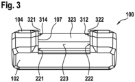
- Fig.3 shows the tool case 100 from Fig.1 with the base element 102 and the cover 104, but without locking tab 105 of Fig.1
- the recess 107 is preferably also formed in the cover 104, the cover 104 having two opposite side surfaces 321, 322 and a connecting surface 323 analogous to the base element 102.
- the cover 104 has at least one locking hook 312, 314.
- two oppositely arranged locking hooks 312, 314 are provided.
- the locking hooks 312, 314 are arranged on the side surfaces 321, 322.
- the at least one locking hook 312, 314 can also be arranged on the base element 102. Furthermore, at least one locking hook 312, 314 can be arranged on the cover 104 and at least one locking hook 312, 314 on the base element 102.
- Fig. 4 shows the locking tab 105 of the tool case 100 from Fig. 1 and Fig. 3 , viewed from its side 499 facing the inside of the case 403.
- the inside of the case 403 is in the closed state of the tool case 100 Fig. 1 arranged facing the base element 102 and the cover 104.
- the insert tool holding device 120 is Fig.1 arranged on the side 499 of the locking tab 105 facing the case inner side 403.
- the insert tool holding device 120 has at least one and illustratively two insert tool holding sections 422, 423.
- Each of the illustratively two insert tool holding sections 422, 423 is preferably designed to releasably hold an insert tool, in particular a screwdriver bit, a drill and/or a bit extension.
- the insert tool holding sections 422, 423 are formed in one piece with the locking tab 105. However, they can Insert tool holding sections 422, 423 can also be fixed to the locking tab 105 via any connection, for example an adhesive, weld and/or screw connection.
- the insert tool holding sections 422, 423 preferably have an at least approximately semicircular receptacle 481 for reversibly holding an insert tool.
- the insert tool holding device 120 has at least one fixing section 434, 435, 436 for fixing an insert tool holding unit (510 in Fig. 5 ) on.
- the at least one fixing section 434, 435, 436 is preferably formed in one piece with the locking tab 105.
- the at least one fixing section 434, 435, 436 can be arranged on the locking tab 105 analogously to the insert tool holding sections 422, 423 via any desired connection, for example an adhesive, welded and/or screwed connection.
- the fixing section 434 is designed as a web on which the at least one fixing section (521, 523 in Fig. 5 ) of the insert tool holder unit (510 in Fig. 5 ). Furthermore, the fixing section 435, which is designed as a recess, preferably as a rectangular recess, is arranged on the fixing section 434. However, the fixing section 435 can also have any other shape, for example an oval or round shape.
- the fixing section 436 is designed as a locking hook and is designed to lock with the insert tool holding unit (510 in Fig. 5 ) educated.
- the locking tab 105 preferably has at least one positioning section 432, 433 for positioning the insert tool holding unit (510 in.) along its longitudinal extent 489 between the fixing sections 434 - 436 Fig. 5 ) on.
- the at least one positioning section 432, 433 is preferably formed in one piece with the locking tab 105.
- the locking tab 105 illustratively has two side walls 485, 486.
- the side walls 485, 486 are parallel to the side surfaces 221, 222 of Fig.2 or 321, 322 of Fig.3 of the base element 102 and the cover 104.
- a pivot pin 442, 444 is provided on each side wall 485, 486 for pivotally mounting the locking tab 105 on the Base element 102, in particular on the bearing supports 202 of the base element 102 of Fig.2 , arranged.
- the locking tab 105 preferably has at least one latching receptacle 414 to form a latching connection with the base element 102 and/or the cover 104.
- the locking receptacle 414 is preferred for forming a locking connection with the locking hooks 312, 314 of the cover 104 Fig. 3 educated.
- the locking receptacle 414 is assigned to a web 415 of the locking tab 105 facing the inside of the case 403.
- the web 415 is illustratively arranged on a top side 488 of the locking tab 105.
- the web 415 is formed along the entire longitudinal extent 489 of the locking tab 105.
- the web 415 could also only be formed on the areas facing the side walls 485, 486.
- the insert tool holding device 120 can alternatively be arranged on a side 498 of the locking tab 105 facing an outer side 401 of the case.
- the outer side 404 of the case is arranged facing away from the base element 102 and the lid 104 when the tool case 100 is closed.
- Fig.5 shows the locking tab 105 with the insert tool holder 120 of Fig.4 and with an insert tool holding unit 510, which can preferably be arranged detachably on the locking tab 105.
- the insert tool holding device 510 has at least one receptacle 520 for receiving an insert tool 530.
- the at least one receptacle 520 preferably has at least one fixing section 521, 522, 523, 524, 525 for detachably fixing an insert tool 530 in the at least one receptacle 520.
- Eight insert tools designed as screwdriver bits are shown illustratively, with only one insert tool being provided with a reference number, ie the insert tool 530.
- the insert tool holding unit 510 has a positioning web 512 which can be inserted into the fixing section 435 of the locking tab 105.
- the positioning web 512 and the fixing section 435 have corresponding shapes.
- the insert tool holding unit 510 has a locking section at its illustrative right end 514.
- the latching section 514 can preferably be latched to the fixing section 436 of the locking tab 105, which is designed as a latching hook. It is pointed out that the positioning web 512 and the latching section 514 can also be arranged laterally reversed, so that the positioning web 512 can be arranged illustratively on the right and the latching section 514 can be arranged illustratively on the left.
- the positioning web 512 and the latching section 514 are preferably arranged opposite one another.
- the positioning web 512 can alternatively also be arranged on a longitudinal side that is aligned parallel to the longitudinal extent 489 of the locking tab 105.
- the insert tool holding unit 510 can alternatively also have a locking section 514 on both sides for locking on both sides with the locking tab 105.
- the locking tab 105 can also have the positioning bar 512 and the insert tool holding unit 510 has a receptacle for the positioning bar 512.
- the locking tab 105 has at least one insert tool holding section 422, 423 for the direct arrangement of at least one insert tool and/or at least one detachable insert tool holding unit 510 that can be arranged on the locking tab 105.
- the insert tool holding device 510 is preferably designed as a bit magazine.
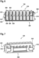
- Fig.6 shows the insert tool holding unit 510 of Fig.5 with insert tools 530 with a front side 601 and a back side 602.
- Fig.6 the opposite arrangement of the positioning web 512 and the locking section 514.
- Fig.6 the at least approximately C-shaped design of the locking section 514.
- Fig. 7 shows the insert tool holding unit 510 from Fig. 5 and Fig. 6 viewed from the back 602. This makes it clear Fig. 7 also the positioning bar 512 and the locking section 514.
Landscapes
- Engineering & Computer Science (AREA)
- Mechanical Engineering (AREA)
- Workshop Equipment, Work Benches, Supports, Or Storage Means (AREA)
- Packaging Of Annular Or Rod-Shaped Articles, Wearing Apparel, Cassettes, Or The Like (AREA)
Abstract
Description
- Die vorliegende Erfindung betrifft einen Werkzeugkoffer mit einem Grundelement und einem Deckel, wobei das Grundelement und der Deckel einen Kofferinnenraum zur Aufnahme von zumindest einer Handwerkzeugmaschine ausbilden, und mit einer Verriegelungslasche zum Verriegeln des Deckels am Grundelement.
- Aus dem Stand der Technik ist ein derartiger Werkzeugkoffer zur Aufnahme von einer Handwerkzeugmaschine bekannt. Der Werkzeugkoffer weist ein Grundelement und einen Deckel auf, die einen Kofferinnenraum ausbilden. In dem Kofferinnenraum ist eine Handwerkzeugmaschine anordenbar. Zum Verriegeln des Deckels am Grundelement ist eine Verriegelungslasche vorgesehen.
- Die Erfindung betrifft einen Werkzeugkoffer mit einem Grundelement und einem Deckel, wobei das Grundelement und der Deckel einen Kofferinnenraum zur Aufnahme von zumindest einer Handwerkzeugmaschine ausbilden, und mit einer Verriegelungslasche zum Verriegeln des Deckels am Grundelement. Die Verriegelungslasche weist eine Einsatzwerkzeughaltevorrichtung zum Halten von zumindest einem Einsatzwerkzeug auf.
- Die Erfindung ermöglicht somit die Bereitstellung eines Werkzeugkoffers, bei dem durch die Verriegelungslasche mit der Einsatzwerkzeughaltevorrichtung eine einfache und kompakte Aufnahme eines Einsatzwerkzeugs im bzw. am Werkzeugkoffer ermöglicht werden kann.
- Bevorzugt ist die Einsatzwerkzeughaltevorrichtung an einer einer Kofferinnenseite zugewandten Seite der Verriegelungslasche angeordnet, wobei die Kofferinnenseite im geschlossenen Zustand des Werkzeugkoffers dem Grundelement und dem Deckel zugewandt angeordnet ist.
- Somit kann eine sichere und geschützte Anordnung der Einsatzwerkzeughaltevorrichtung, bzw. von zumindest einem Einsatzwerkzeug, am Werkzeugkoffer ermöglicht werden.
- Vorzugsweise ist die Einsatzwerkzeughaltevorrichtung an einer einer Kofferaußenseite zugewandten Seite der Verriegelungslasche angeordnet, die im geschlossenen Zustand des Werkzeugkoffers vom Grundelement und vom Deckel abgewandt angeordnet ist.
- Somit kann eine alternative Anordnung der Einsatzwerkzeughaltevorrichtung, bzw. von zumindest einem Einsatzwerkzeug, am Werkzeugkoffer ermöglicht werden.
- Die Einsatzwerkzeughaltevorrichtung weist vorzugsweise mindestens einen Einsatzwerkzeughalteabschnitt auf, der einstückig mit der Verriegelungslasche ausgebildet ist.
- Somit kann eine stabile und robuste Ausgestaltung des Einsatzwerkzeughalteabschnitts als integraler Bestandteil der Verriegelungslasche ermöglicht werden.
- Bevorzugt weist die Einsatzwerkzeughaltevorrichtung mindestens einen Fixierabschnitt zum Fixieren einer Einsatzwerkzeughalteeinheit auf, wobei der mindestens eine Fixierabschnitt einstückig mit der Verriegelungslasche ausgebildet ist.
- Somit kann eine sichere und zuverlässige Fixierung sowie eine reversible Anordnung der Einsatzwerkzeughalteeinheit an der Verriegelungslasche ermöglicht werden.
- Die Einsatzwerkzeughalteeinheit weist bevorzugt einen Positioniersteg auf, der in dem Fixierabschnitt der Verriegelungslasche einsteckbar ist.
- Somit kann eine leichte und unkomplizierte Fixierung der Einsatzwerkzeughalteeinheit an der Verriegelungslasche ermöglicht werden.
- Vorzugsweise weist die Einsatzwerkzeughalteeinheit zumindest einen Rastabschnitt auf, der mit dem als Rasthaken ausgebildeten Fixierabschnitt der Verriegelungslasche verrastbar ist.
- Somit kann auf einfache Art und Weise eine alternative Fixierung der Einsatzwerkzeughalteeinheit an der Verriegelungslasche ermöglicht werden.
- Gemäß einer Ausführungsform weist die Einsatzwerkzeughalteeinheit zumindest eine Aufnahme zum Aufnehmen eines Einsatzwerkzeugs auf, wobei die Aufnahme mindestens einen Fixierabschnitt zum lösbaren Fixieren eines Einsatzwerkzeugs in der Aufnahme aufweist.
- Somit kann eine sichere und zuverlässige Anordnung eines Einsatzwerkzeugs in der Einsatzwerkzeughalteeinheit ermöglicht werden.
- Bevorzugt weist die Verriegelungslasche mindestens eine Rastaufnahme auf und das Grundelement und/oder der Deckel weist einen der mindestens einen Rastaufnahme zugeordneten Rasthaken zur Ausbildung einer Rastverbindung auf.
- Somit kann eine stabile und robuste Verriegelung der Verriegelungslasche am Grundelement und/oder Deckel durch eine Rastverbindung der Verriegelungslasche ermöglicht werden.
- Gemäß einer Ausführungsform bilden das Grundelement und der Deckel jeweils eine Ausnehmung aus, wobei die Verriegelungslasche im geschlossenen Zustand des Werkzeugkoffers in der Ausnehmung angeordnet ist.
- Somit kann auf einfache Art und Weise ein kompakter Werkzeugkoffer bereitgestellt werden.
- Kurze Beschreibung der Zeichnungen
- Die Erfindung ist anhand von in den Zeichnungen dargestellten Ausführungsbeispielen in der nachfolgenden Beschreibung näher erläutert. Es zeigen:
- Fig. 1
- eine perspektivische Ansicht eines Werkzeugkoffers mit einem Grundelement, einem Deckel und einer Verriegelungslasche,
- Fig. 2
- eine perspektivische Ansicht des Grundelements von
Fig. 1 mit einer Handwerkzeugmaschine, - Fig. 3
- eine perspektivische Frontansicht des Grundelements und des Deckels des Werkzeugkoffers von
Fig. 1 und Fig. 2 , - Fig. 4
- eine perspektivische Ansicht der Verriegelungslasche des Werkzeugkoffers von
Fig. 1 bis Fig. 3 , von einer Innenseite aus betrachtet, - Fig. 5
- eine perspektivische Ansicht der Verriegelungslasche von
Fig. 4 mit einer Einsatzwerkzeughalteeinheit und Einsatzwerkzeugen, - Fig. 6
- eine perspektivische Ansicht der Einsatzwerkzeughalteeinheit mit den Einsatzwerkzeugen von
Fig. 5 , von einer Vorderseite her betrachtet, und - Fig. 7
- eine perspektivische Ansicht der Einsatzwerkzeughalteeinheit von
Fig. 6 , von einer Rückseite aus betrachtet. - In den Figuren werden Elemente mit gleicher oder vergleichbarer Funktion mit identischen Bezugszeichen versehen und nur einmal genauer beschrieben.
-
Fig. 1 zeigt einen beispielhaften Werkzeugkoffer 100 mit einem Grundelement 102 und einem Deckel 104, die vorzugsweise einen Kofferinnenraum (210 inFig. 2 ) zur Lagerung und/oder zum Transport mindestens eines schematisch angedeuteten Transportgegenstands 190 ausbilden. Bevorzugt ist der Transportgegenstand 190 eine vorzugsweise kompakte Handwerkzeugmaschine. Gemäß einer Ausführungsform ist der Transportgegenstand 190 als Stabschrauber, insbesondere als akkubetriebener Stabschrauber ausgebildet. - Der illustrativ kompakte Werkzeugkoffer 100 weist eine Breite B, eine Länge L und eine Höhe H auf. Bevorzugt liegt die Länge L zwischen 200 mm und 250 mm und weist vorzugsweise 220 mm auf. Vorzugsweise liegt die Breite B zwischen 80 mm und 100 mm und weist bevorzugt 80 mm auf. Des Weiteren liegt die Höhe H vorzugsweise zwischen 50 mm und 70 mm und weist bevorzugt 55 mm auf. Der Deckel 104 und/oder das Grundelement 102 sind vorzugsweise halbschalenförmig ausgebildet. Bevorzugt ist der Werkzeugkoffer 100 über eine Verriegelungslasche 105 verschließbar. Hierbei ist die Verriegelungslasche 105 in der in
Fig. 1 gezeigten Ausgestaltung zum Verriegeln des Deckels 104 am Grundelement 102 ausgebildet. Jedoch kann die Verriegelungslasche 105 auch zum Verriegeln des Grundelements 102 am Deckel 104 ausgebildet sein. - Eine Verriegelung des Werkzeugkoffers 100, d.h. des Deckels 104 am Grundelement 102 oder umgekehrt, erfolgt vorzugsweise über eine geeignete Verriegelungsverbindung 110. Bevorzugt ist die Verriegelungsverbindung 110 als Rastverbindung ausgebildet. Jedoch kann die Verriegelungsverbindung 110 auch nach Art einer beliebig anderen Verbindung ausgebildet sein, z.B. als Klemmverbindung, einer Verbindung über ein Sperrelement wie einem Sperrriegel, usw.
- Vorzugsweise bilden das Grundelement 102 und der Deckel 104 jeweils eine Ausnehmung 107 aus, wobei die Verriegelungslasche 105 im in
Fig. 1 gezeigten geschlossenen Zustand des Werkzeugkoffers 100 in der Ausnehmung 107 angeordnet ist. Erfindungsgemäß weist die Verriegelungslasche 105 eine Einsatzwerkzeughaltevorrichtung 120 zum Halten von zumindest einem Einsatzwerkzeug (530 inFig. 5 ) auf. -
Fig. 2 zeigt das Grundelement 102 des Werkzeugkoffers 100 vonFig. 1 . Das Grundelement 102 weist vorzugsweise eine Aufnahme 205 zur teilweisen Aufnahme einer hier als Stabschrauber ausgebildeten Handwerkzeugmaschine 190 auf. Bevorzugt weist der Deckel 104 vonFig. 1 analog zum Grundelement 102 eine Aufnahme 205 zur teilweisen Aufnahme der Handwerkzeugmaschine 190 auf, wobei die beiden Aufnahmen 205 einen Kofferinnenraum 210 ausbilden. - Des Weiteren verdeutlicht
Fig. 2 die Ausnehmung 107 zur Anordnung der Verriegelungslasche 105 vonFig. 1 . Die Ausnehmung 107 ist vorzugsweise rechteckig mit zwei gegenüberliegenden Seitenflächen 221, 222 und einer Verbindungsfläche 223 ausgebildet. Die Verbindungsfläche 223 ist dabei zumindest annähernd senkrecht zu den Seitenflächen 221, 222 angeordnet. Bevorzugt weisen die beiden Seitenflächen 221, 222 jeweils eine Lagerungsaufnahme 202 zum schwenkbaren Lagern der Verriegelungslasche 105 vonFig. 1 auf. Jedoch können die Lagerungsaufnahmen 202 auch am Deckel 104 vonFig. 1 ausgebildet sein. Die Ausnehmung 107 kann auch eine alternative Form aufweisen, z.B. oval. Es wird darauf hingewiesen, dass der Werkzeugkoffer 100 alternativ auch ohne Ausnehmung 107 ausgebildet sein kann. -
Fig. 3 zeigt den Werkzeugkoffer 100 vonFig. 1 mit dem Grundelement 102 und dem Deckel 104, jedoch ohne Verriegelungslasche 105 vonFig. 1 . Die Ausnehmung 107 ist bevorzugt auch im Deckel 104 ausgebildet, wobei der Deckel 104 zwei gegenüberliegende Seitenflächen 321, 322 und eine Verbindungsfläche 323 analog zum Grundelement 102 aufweist. Zur Ausbildung einer bevorzugten Rastverbindung mit der Verriegelungslasche 105 weist der Deckel 104 mindestens einen Rasthaken 312, 314 auf. Illustrativ sind zwei gegenüberliegend angeordnete Rasthaken 312, 314 vorgesehen. Die Rasthaken 312, 314 sind dabei an den Seitenflächen 321, 322 angeordnet. - Es wird darauf hingewiesen, dass der zumindest eine Rasthaken 312, 314 auch am Grundelement 102 angeordnet sein kann. Des Weiteren kann auch mindestens ein Rasthaken 312, 314 am Deckel 104 und mindestens ein Rasthaken 312, 314 am Grundelement 102 angeordnet sein.
-
Fig. 4 zeigt die Verriegelungslasche 105 des Werkzeugkoffers 100 vonFig. 1 undFig. 3 , von ihrer einer Kofferinnenseite 403 zugewandten Seite 499 aus betrachtet. Die Kofferinnenseite 403 ist im geschlossenen Zustand des Werkzeugkoffers 100 vonFig. 1 dem Grundelement 102 und dem Deckel 104 zugewandt angeordnet. - Bevorzugt ist die Einsatzwerkzeughaltevorrichtung 120 von
Fig. 1 an der der Kofferinnenseite 403 zugewandten Seite 499 der Verriegelungslasche 105 angeordnet. Vorzugsweise weist die Einsatzwerkzeughaltevorrichtung 120 mindestens einen und illustrativ zwei Einsatzwerkzeughalteabschnitte 422, 423 auf. Jeder der illustrativ zwei Einsatzwerkzeughalteabschnitte 422, 423 ist bevorzugt jeweils zum lösbaren Halten eines Einsatzwerkzeugs, insbesondere eines Schrauberbits, eines Bohrers und/oder einer Bitverlängerung ausgebildet. - Gemäß einer Ausführungsform sind die Einsatzwerkzeughalteabschnitte 422, 423 einstückig mit der Verriegelungslasche 105 ausgebildet. Jedoch können die Einsatzwerkzeughalteabschnitte 422, 423 auch über eine beliebige Verbindung, z.B. eine Kleb-, Schweiß- und/oder Schraubverbindung an der Verriegelungslasche 105 fixiert sein. Vorzugsweise weisen die Einsatzwerkzeughalteabschnitte 422, 423 eine zumindest annähernd halbrunde Aufnahme 481 zur reversiblen Aufnahme eines Einsatzwerkzeugs auf.
- Alternativ oder optional weist die Einsatzwerkzeughaltevorrichtung 120 mindestens einen Fixierabschnitt 434, 435, 436 zum Fixieren einer Einsatzwerkzeughalteeinheit (510 in
Fig. 5 ) auf. Bevorzugt ist der mindestens eine Fixierabschnitt 434, 435, 436 einstückig mit der Verriegelungslasche 105 ausgebildet. Jedoch kann der mindestens eine Fixierabschnitt 434, 435, 436 analog zu den Einsatzwerkzeughalteabschnitten 422, 423 über eine beliebige Verbindung, z.B. Kleb-, Schweiß- und/oder Schraubverbindung an der Verriegelungslasche 105 angeordnet sein. - Illustrativ ist der Fixierabschnitt 434 als Steg ausgebildet, an dem der mindestens eine Fixierabschnitt (521, 523 in
Fig. 5 ) der Einsatzwerkzeughalteeinheit (510 inFig. 5 ) anliegt. Des Weiteren ist am Fixierabschnitt 434 das als Ausnehmung, vorzugsweise als rechteckige Ausnehmung ausgebildete Fixierabschnitt 435 angeordnet. Jedoch kann das Fixierabschnitt 435 auch eine beliebig andere Form aufweisen, z.B. eine ovale oder runde Form. Das Fixierabschnitt 436 ist als Rasthaken ausgebildet und zum Verrasten mit der Einsatzwerkzeughalteeinheit (510 inFig. 5 ) ausgebildet. - Des Weiteren weist die Verriegelungslasche 105 entlang ihrer Längserstreckung 489 zwischen den Fixierabschnitten 434 - 436 vorzugsweise zumindest einen Positionierungsabschnitt 432, 433 zum Positionieren der Einsatzwerkzeughalteeinheit (510 in
Fig. 5 ) auf. Bevorzugt ist der zumindest eine Positionierungsabschnitt 432, 433 einstückig mit der Verriegelungslasche 105 ausgebildet. - Darüber hinaus weist die Verriegelungslasche 105 illustrativ zwei Seitenwände 485, 486 auf. Die Seitenwände 485, 486 sind parallel zu den Seitenflächen 221, 222 von
Fig. 2 bzw. 321, 322 vonFig. 3 des Grundelements 102 und des Deckels 104 angeordnet. Vorzugsweise ist an jeder Seitenwand 485, 486 ein Drehzapfen 442, 444 zur schwenkbaren Lagerung der Verriegelungslasche 105 am Grundelement 102, insbesondere an den Lagerungsaufnahmen 202 des Grundelements 102 vonFig. 2 , angeordnet. - Vorzugsweise weist die Verriegelungslasche 105 mindestens eine Rastaufnahme 414 zur Ausbildung einer Rastverbindung mit dem Grundelement 102 und/oder dem Deckel 104 auf. Die Rastaufnahme 414 ist bevorzugt zur Ausbildung einer Rastverbindung mit den Rasthaken 312, 314 des Deckels 104 von
Fig. 3 ausgebildet. Die Rastaufnahme 414 ist einem der Kofferinnenseite 403 zugewandten Steg 415 der Verriegelungslasche 105 zugeordnet. Der Steg 415 ist illustrativ an einer Oberseite 488 der Verriegelungslasche 105 angeordnet. Illustrativ ist der Steg 415 entlang der kompletten Längserstreckung 489 der Verriegelungslasche 105 ausgebildet. Jedoch könnte der Steg 415 auch nur an den den Seitenwänden 485, 486 zugewandten Bereichen ausgebildet sein. - Es wird darauf hingewiesen, dass die Einsatzwerkzeughaltevorrichtung 120 alternativ an einer einer Kofferaußenseite 401 zugewandten Seite 498 der Verriegelungslasche 105 angeordnet sein kann. Die Kofferaußenseite 404 ist im geschlossenen Zustand des Werkzeugkoffers 100 vom Grundelement 102 und vom Deckel 104 abgewandt angeordnet.
-
Fig. 5 zeigt die Verriegelungslasche 105 mit der Einsatzwerkzeughaltevorrichtung 120 vonFig. 4 und mit einer Einsatzwerkzeughalteeinheit 510, die bevorzugt lösbar an der Verriegelungslasche 105 anordenbar ist. Die Einsatzwerkzeughaltevorrichtung 510 weist zumindest eine Aufnahme 520 zum Aufnehmen eines Einsatzwerkzeugs 530 auf. Vorzugsweise weist die zumindest eine Aufnahme 520 mindestens einen Fixierabschnitt 521, 522, 523, 524, 525 zum lösbaren Fixieren eines Einsatzwerkzeugs 530 in der zumindest einen Aufnahme 520 auf. Illustrativ sind acht als Schrauberbit ausgebildete Einsatzwerkzeuge gezeigt, wobei lediglich ein Einsatzwerkzeug mit einer Bezugszifferversehen ist, d.h. das Einsatzwerkzeug 530. - An seinem illustrativ linken Ende weist die Einsatzwerkzeughalteeinheit 510 einen Positioniersteg 512 auf, der in den Fixierabschnitt 435 der Verriegelungslasche 105 einsteckbar ist. Hierfür weisen der Positioniersteg 512 und der Fixierabschnitt 435 korrespondierende Formen auf. Darüber hinaus weist die Einsatzwerkzeughalteeinheit 510 an ihrem illustrativ rechten Ende einen Rastabschnitt 514 auf. Bevorzugt ist der Rastabschnitt 514 mit dem als Rasthaken ausgebildeten Fixierabschnitt 436 der Verriegelungslasche 105 verrastbar. Es wird darauf hingewiesen, dass der Positioniersteg 512 und der Rastabschnitt 514 auch seitenverkehrt angeordnet sein können, sodass der Positioniersteg 512 illustrativ rechts angeordnet sein kann und der Rastabschnitt 514 illustrativ links angeordnet sein kann. Bevorzugt sind der Positioniersteg 512 und der Rastabschnitt 514 gegenüberliegend angeordnet.
- Der Positioniersteg 512 kann alternativ auch an einer Längsseite, die parallel zur Längserstreckung 489 der Verriegelungslasche 105 ausgerichtet ist, angeordnet sein. Des Weiteren kann die Einsatzwerkzeughalteeinheit 510 alternativ auch beidseitig einen Rastabschnitt 514 zum beidseitigen Verrasten mit der Verriegelungslasche 105 aufweisen. Darüber hinaus kann die Verriegelungslasche 105 auch den Positioniersteg 512 aufweisen und die Einsatzwerkzeughalteeinheit 510 weist eine Aufnahme für den Positioniersteg 512 auf.
- Gemäß einer Ausführungsform weist die Verriegelungslasche 105 zumindest einen Einsatzwerkzeughalteabschnitt 422, 423 zur direkten Anordnung von mindestens einem Einsatzwerkzeug und/oder zumindest eine lösbare an der Verriegelungslasche 105 anordenbare Einsatzwerkzeughalteeinheit 510 auf. Bevorzugt ist die Einsatzwerkzeughaltevorrichtung 510 als Bitmagazin ausgebildet.
-
Fig. 6 zeigt die Einsatzwerkzeughalteeinheit 510 vonFig. 5 mit Einsatzwerkzeugen 530 mit einer Vorderseite 601 und einer Rückseite 602. Dabei verdeutlichtFig. 6 die gegenüberliegende Anordnung des Positionierstegs 512 und des Rastabschnitts 514. Hierbei zeigtFig. 6 die zumindest annähernd C-förmige Ausbildung des Rastabschnitts 514. -
Fig. 7 zeigt die Einsatzwerkzeughalteeinheit 510 vonFig. 5 undFig. 6 von der Rückseite 602 aus betrachtet. Dabei verdeutlichtFig. 7 ebenfalls den Positioniersteg 512 und den Rastabschnitt 514.
Claims (10)
- Werkzeugkoffer (100) mit einem Grundelement (102) und einem Deckel (104), wobei das Grundelement (102) und der Deckel (104) einen Kofferinnenraum (210) zur Aufnahme von zumindest einer Handwerkzeugmaschine (190) ausbilden, und mit einer Verriegelungslasche (105) zum Verriegeln des Deckels (104) am Grundelement (102), dadurch gekennzeichnet, dass die Verriegelungslasche (105) eine Einsatzwerkzeughaltevorrichtung (120) zum Halten von zumindest einem Einsatzwerkzeug (530) aufweist.
- Werkzeugkoffer nach Anspruch 1, dadurch gekennzeichnet, dass die Einsatzwerkzeughaltevorrichtung (120) an einer einer Kofferinnenseite (403) zugewandten Seite (499) der Verriegelungslasche (105) angeordnet ist, wobei die Kofferinnenseite (403) im geschlossenen Zustand des Werkzeugkoffers (100) dem Grundelement (102) und dem Deckel (104) zugewandt angeordnet ist.
- Werkzeugkoffer nach Anspruch 1, dadurch gekennzeichnet, dass die Einsatzwerkzeughaltevorrichtung (120) an einer einer Kofferaußenseite (401) zugewandten Seite (498) der Verriegelungslasche (105) angeordnet ist, die im geschlossenen Zustand des Werkzeugkoffers (100) vom Grundelement (102) und vom Deckel (104) abgewandt angeordnet ist.
- Werkzeugkoffer nach einem der vorhergehenden Ansprüche, dadurch gekennzeichnet, dass die Einsatzwerkzeughaltevorrichtung (120) mindestens einen Einsatzwerkzeughalteabschnitt (422, 423) aufweist, der einstückig mit der Verriegelungslasche (105) ausgebildet ist.
- Werkzeugkoffer nach einem der vorhergehenden Ansprüche, dadurch gekennzeichnet, dass die Einsatzwerkzeughaltevorrichtung (120) mindestens einen Fixierabschnitt (434, 435, 436) zum Fixieren einer Einsatzwerkzeughalteeinheit (510) aufweist, wobei der mindestens eine Fixierabschnitt (434, 435, 436) einstückig mit der Verriegelungslasche (105) ausgebildet ist.
- Werkzeugkoffer nach Anspruch 5, dadurch gekennzeichnet, dass die Einsatzwerkzeughalteeinheit (510) einen Positioniersteg (512) aufweist, der in dem Fixierabschnitt (435) der Verriegelungslasche (105) einsteckbar ist.
- Werkzeugkoffer nach Anspruch 5 oder 6, dadurch gekennzeichnet, dass die Einsatzwerkzeughalteeinheit (510) zumindest einen Rastabschnitt (514) aufweist, der mit dem als Rasthaken ausgebildeten Fixierabschnitt (436) der Verriegelungslasche (105) verrastbar ist.
- Werkzeugkoffer nach einem der Ansprüche 5 bis 7, dadurch gekennzeichnet, dass die Einsatzwerkzeughalteeinheit (510) zumindest eine Aufnahme (520) zum Aufnehmen eines Einsatzwerkzeugs (530) aufweist, wobei die Aufnahme (520) mindestens einen Fixierabschnitt (521, 522, 523, 524, 525) zum lösbaren Fixieren eines Einsatzwerkzeugs (530) in der Aufnahme (520) aufweist.
- Werkzeugkoffer nach einem der vorhergehenden Ansprüche, dadurch gekennzeichnet, dass die Verriegelungslasche (105) mindestens eine Rastaufnahme (414) aufweist, und das Grundelement (102) und/oder der Deckel (104) einen der mindestens einen Rastaufnahme (414) zugeordneten Rasthaken (312, 314) zur Ausbildung einer Rastverbindung aufweist.
- Werkzeugkoffer nach einem der vorhergehenden Ansprüche, dadurch gekennzeichnet, dass das Grundelement (102) und der Deckel (104) jeweils eine Ausnehmung (107) ausbilden, wobei die Verriegelungslasche (105) im geschlossenen Zustand des Werkzeugkoffers (100) in der Ausnehmung (107) angeordnet ist.
Applications Claiming Priority (1)
| Application Number | Priority Date | Filing Date | Title |
|---|---|---|---|
| DE102022210256.8A DE102022210256A1 (de) | 2022-09-28 | 2022-09-28 | Werkzeugkoffer für eine Handwerkzeugmaschine |
Publications (2)
| Publication Number | Publication Date |
|---|---|
| EP4344830A1 true EP4344830A1 (de) | 2024-04-03 |
| EP4344830B1 EP4344830B1 (de) | 2025-05-14 |
Family
ID=87762817
Family Applications (1)
| Application Number | Title | Priority Date | Filing Date |
|---|---|---|---|
| EP23192955.5A Active EP4344830B1 (de) | 2022-09-28 | 2023-08-23 | Werkzeugkoffer für eine handwerkzeugmaschine |
Country Status (5)
| Country | Link |
|---|---|
| US (1) | US20240100683A1 (de) |
| EP (1) | EP4344830B1 (de) |
| CN (1) | CN117773864A (de) |
| DE (1) | DE102022210256A1 (de) |
| GB (1) | GB2622956A (de) |
Families Citing this family (2)
| Publication number | Priority date | Publication date | Assignee | Title |
|---|---|---|---|---|
| CN219170872U (zh) * | 2021-07-22 | 2023-06-13 | 米沃奇电动工具公司 | 工具附件保持器、工具系统和工具附件存储系统 |
| USD1077481S1 (en) * | 2025-01-17 | 2025-06-03 | Yifei He | Toolbox |
Citations (3)
| Publication number | Priority date | Publication date | Assignee | Title |
|---|---|---|---|---|
| DE102004060294A1 (de) * | 2004-12-15 | 2006-06-22 | Robert Bosch Gmbh | Vorrichtung mit einem Handwerkzeugmaschinenkoffer |
| DE102005052427A1 (de) * | 2005-11-03 | 2007-05-10 | Robert Bosch Gmbh | Handwerkzeugmaschinenkoffer |
| DE202010000340U1 (de) * | 2010-03-09 | 2010-05-27 | Plaston Ag | Koffersystem |
Family Cites Families (88)
| Publication number | Priority date | Publication date | Assignee | Title |
|---|---|---|---|---|
| US3339781A (en) * | 1965-03-22 | 1967-09-05 | Grace W R & Co | Hollow wall container |
| US3371975A (en) * | 1967-02-21 | 1968-03-05 | Henry E. Meltzer | Cooling and carrying box for electric tools and appliances |
| US3822083A (en) * | 1973-02-08 | 1974-07-02 | Scm Corp | Typewriter case |
| US4927021A (en) * | 1987-05-26 | 1990-05-22 | Taylor Steven C | Installer's briefcase |
| US4917239A (en) * | 1989-04-17 | 1990-04-17 | Smith Vincent K | Automotive electric power tool auto and kit |
| DE9013289U1 (de) * | 1990-09-20 | 1992-01-30 | Wera-Werk Hermann Werner Gmbh & Co, 5600 Wuppertal | Box zur Aufnahme von Schraubendrehereinsätzen |
| US5203469A (en) * | 1992-06-01 | 1993-04-20 | Roger Chang | Tool box |
| US5570784A (en) * | 1992-12-24 | 1996-11-05 | Allied Wholesale, Inc. | Tool organizer and deployment apparatus |
| US5271501A (en) * | 1993-02-12 | 1993-12-21 | Tung I Enterprise Co., Ltd. | Toolbox |
| US5368164A (en) * | 1993-11-30 | 1994-11-29 | Allied Wholesale, Inc. | Tool set apparatus |
| US5533843A (en) * | 1994-09-19 | 1996-07-09 | Chung; Lee H.-C. | Electric hand drill set |
| US5769260A (en) * | 1996-08-21 | 1998-06-23 | Flambeau Products Corp. | Molded plastic storage container |
| US6105767A (en) * | 1997-04-11 | 2000-08-22 | Maxtech, Inc. | Tool case with butterfly door |
| US5826718A (en) * | 1997-06-20 | 1998-10-27 | Rubbermaid Incorporated | Tool box with bin-carrying cover |
| AU8723898A (en) * | 1997-08-08 | 1999-03-01 | Maxtech Manufacturing Inc. | Toolboxes and tool cases with pivotable component holder |
| US6267238B1 (en) * | 1999-12-30 | 2001-07-31 | Hand Tools International, Llc | Case for power tool having attached power cord |
| US6571949B2 (en) * | 2000-06-05 | 2003-06-03 | Motorola, Inc. | Power toolbox |
| US6454092B1 (en) * | 2000-12-15 | 2002-09-24 | Pei Ling Lee | Tool engaging cavity of tool box |
| US6789670B2 (en) * | 2001-11-12 | 2004-09-14 | Black & Decker Inc. | Power tool carrying case |
| US6695142B2 (en) * | 2002-05-03 | 2004-02-24 | Stanley Chiro International, Ltd. | Tool storage unit capable of firm retention of a socket |
| US20040065574A1 (en) * | 2002-10-03 | 2004-04-08 | Hernandez Hector R. | Tool case with a hinged cover that slides |
| US20040069668A1 (en) * | 2002-10-09 | 2004-04-15 | Robert Finnigan | Tool-element holding case |
| US6662945B1 (en) * | 2002-11-04 | 2003-12-16 | Joinery Industrial Co., Ltd. | Toolbox with stereo |
| US7225923B2 (en) * | 2002-12-17 | 2007-06-05 | Irwin Industrial Tool Company | Multi-configured tool bit box |
| US6981780B2 (en) * | 2002-12-31 | 2006-01-03 | Zag Industries Ltd. | Tool box with light |
| US6953114B2 (en) * | 2003-04-09 | 2005-10-11 | Mei-Chen Wang | Toolbox |
| US20050031458A1 (en) * | 2003-08-07 | 2005-02-10 | Brashears Richard K. | Portable air compressor |
| DE10356066A1 (de) * | 2003-12-01 | 2005-06-23 | Robert Bosch Gmbh | Koffer, insbesondere Werkzeugmaschinenkoffer |
| US6971517B2 (en) * | 2004-05-06 | 2005-12-06 | Kun-Chen Chen | Attache style toolbox with an outer frame |
| DE202005001405U1 (de) * | 2005-01-28 | 2006-06-01 | Rösler, Peter | Kassette mit Längenanschlag |
| US7401700B2 (en) * | 2005-02-22 | 2008-07-22 | Robert Bosch Gmbh | Tool accessory case index |
| US7367451B2 (en) * | 2005-03-03 | 2008-05-06 | Robert Bosch Gmbh | Tool accessory case having product indicator indicia surface inserts |
| US20060201835A1 (en) * | 2005-03-09 | 2006-09-14 | Test Rite Products Corporation | Tool organizer |
| US7780016B1 (en) * | 2005-07-08 | 2010-08-24 | Jore Corporation | Tool holder |
| US20070095690A1 (en) * | 2005-10-26 | 2007-05-03 | Chanwa Nguy | Transparent plastic container having aperture for receiving tool handle |
| US20080017537A1 (en) * | 2006-06-08 | 2008-01-24 | Matthew Inskeep | Accessory case |
| US20080060967A1 (en) * | 2006-09-07 | 2008-03-13 | Ming-Chi Chang | Toolbox with covers covering upon an outer surface of the box body |
| CA2682142C (en) * | 2007-03-28 | 2013-01-22 | Custom-Pak, Inc. | Soft plastic insert for use in protective case |
| JP2009248262A (ja) * | 2008-04-08 | 2009-10-29 | Makita Corp | 工具収納箱 |
| US20090314674A1 (en) * | 2008-06-18 | 2009-12-24 | James Earl Sauerheber | Tool case |
| DE102009027574B4 (de) * | 2009-07-09 | 2018-01-25 | Robert Bosch Gmbh | Werkzeugkoffer, insbesondere Handwerkzeugkoffer |
| US20110011760A1 (en) * | 2009-07-14 | 2011-01-20 | Wal-Mart Stores, Inc. | Live device seizure kit |
| US8267245B2 (en) * | 2009-09-02 | 2012-09-18 | Black & Decker Inc. | Method and package for displaying magnetic tool container |
| WO2011103638A1 (en) * | 2010-02-25 | 2011-09-01 | Demain Technology Pty Ltd | A power tool storage and package system |
| US20130051080A1 (en) * | 2010-02-25 | 2013-02-28 | Demain Technology Pty Ltd | Power station assembly |
| DE102011002409A1 (de) * | 2010-05-27 | 2011-12-01 | Robert Bosch Gmbh | Handwerkzeugkoffer |
| US8646600B2 (en) * | 2011-04-28 | 2014-02-11 | The Plastic Forming Company, Inc. | Blow-molded tool kit |
| JP5739266B2 (ja) * | 2011-05-09 | 2015-06-24 | 株式会社マキタ | 電動工具用収納ケース |
| JP5767872B2 (ja) * | 2011-06-27 | 2015-08-26 | 株式会社マキタ | 電動工具用収納ケース |
| US8505720B2 (en) * | 2011-08-12 | 2013-08-13 | Kevin Huang | Tool positioning pad |
| DE102011086874A1 (de) * | 2011-11-22 | 2013-05-23 | Robert Bosch Gmbh | Handwerkzeugkoffer |
| DE102011086884A1 (de) * | 2011-11-22 | 2013-05-23 | Robert Bosch Gmbh | Handwerkzeugkoffer |
| DE102012204407B4 (de) * | 2012-03-20 | 2024-08-01 | Robert Bosch Gmbh | System zumindest mit einem Handwerkzeugkoffer und einem Baustellenradio |
| JP5815445B2 (ja) * | 2012-03-21 | 2015-11-17 | 株式会社マキタ | 工具収納ケース |
| US8646601B2 (en) * | 2012-04-23 | 2014-02-11 | Irwin Industrial Tool Company | Hole saw kit |
| US8678185B1 (en) * | 2012-12-06 | 2014-03-25 | Yi-Hung Lin | Tool box |
| US9539722B2 (en) * | 2012-12-19 | 2017-01-10 | Milwaukee Electric Tool Corporation | Tool storage devices |
| JP2014128851A (ja) * | 2012-12-28 | 2014-07-10 | Makita Corp | 工具収容ケース、及び、サブケース |
| EP2815853B1 (de) * | 2013-06-20 | 2018-02-07 | The Stanley Works Israel Ltd. | Werkzeugkasten |
| US20170063114A1 (en) * | 2013-11-15 | 2017-03-02 | Christian Fitch BRIERE | Multi-port battery charging apparatus, system and kit |
| JP6450084B2 (ja) * | 2014-04-08 | 2019-01-09 | 株式会社マキタ | 電動工具及びその販売システム |
| WO2015184647A1 (en) * | 2014-06-06 | 2015-12-10 | Techtronic Industries Company Limited | Blow molded container |
| US9625143B2 (en) * | 2014-08-20 | 2017-04-18 | Shao-Hsien HSU | Tool box with illumination unit |
| DE102014226234A1 (de) * | 2014-12-17 | 2016-06-23 | Robert Bosch Gmbh | Handwerkzeugkoffer |
| US9987741B2 (en) * | 2015-02-12 | 2018-06-05 | Techtronic Industries Co. Ltd. | Tool bit case |
| DE202015101261U1 (de) * | 2015-03-11 | 2015-03-23 | Kwb Germany Gmbh | Aufbewahrungsvorrichtung für Werkzeugeinsätze |
| US9512648B2 (en) * | 2015-04-02 | 2016-12-06 | I-N-B International Inc. | Lockable tool box |
| US10468755B2 (en) * | 2016-03-07 | 2019-11-05 | Plum Laboratories, LLC | Data communications system for a vehicle |
| DE102016209490A1 (de) * | 2016-05-31 | 2017-11-30 | Robert Bosch Gmbh | Werkzeugaufbewahrungsvorrichtung |
| US10350747B2 (en) * | 2016-12-27 | 2019-07-16 | Lin Lin Weng | Dynamic toolbox |
| US10500714B2 (en) * | 2017-03-02 | 2019-12-10 | Terrifictools, Inc. | Truss-supported tool transport apparatus |
| DE202017103624U1 (de) * | 2017-06-20 | 2017-08-04 | Kun-Meng Lin | Mit einem Handgriff eines Werkzeugs tragbarer Werkzeugkoffer |
| WO2019119508A1 (zh) * | 2017-12-21 | 2019-06-27 | 丹阳市剑庐工具有限公司 | 一种大容量三开自锁工具盒 |
| US10574067B1 (en) * | 2018-07-18 | 2020-02-25 | James Hanson | Multi-purpose utility box |
| CN112805123B (zh) * | 2018-09-10 | 2024-07-30 | 米沃奇电动工具公司 | 模块化工具容器 |
| WO2020131269A1 (en) * | 2018-12-20 | 2020-06-25 | Apex Brands, Inc. | Rotating and removable bit/driver rails |
| US20210078157A1 (en) * | 2019-09-18 | 2021-03-18 | Custom-Pak, Inc. | Carrying Case |
| US11622668B2 (en) * | 2020-01-22 | 2023-04-11 | Solemate Golf Llc | Kit with electrically energized rotary brush for cleaning shoe soles |
| DE102020103316A1 (de) * | 2020-02-10 | 2021-08-12 | Adolf Würth GmbH & Co. KG | Block zum Aufnehmen von Werkzeugelementen in einer Werkzeuganordnung |
| DE102020103322A1 (de) * | 2020-02-10 | 2021-08-12 | Adolf Würth Gmbh & Co Kg | Werkzeugverwaltungsvorrichtung mit Kulissenführung sowie Zapfen an Gelenkverbindung |
| US20220081193A1 (en) * | 2020-08-12 | 2022-03-17 | Aob Products Company | Knife case |
| TWI755192B (zh) * | 2020-12-08 | 2022-02-11 | 金統立工業股份有限公司 | 工具盒 |
| US11472020B2 (en) * | 2021-01-15 | 2022-10-18 | Stanley Black & Decker, Inc. | Utility knife blade holder for tool container system |
| US20220355462A1 (en) * | 2021-05-05 | 2022-11-10 | Yao-Lin Cho | Tool box |
| US11827415B2 (en) * | 2021-09-16 | 2023-11-28 | Techtronic Cordless Gp | Storage box light |
| US20230150109A1 (en) * | 2021-11-17 | 2023-05-18 | Jeng Sheng Co., Ltd. | Storage bag |
| WO2023107284A1 (en) * | 2021-12-08 | 2023-06-15 | Lucid Concepts, LLC | Sled systems for cutting stored materials and for storing elongated and flexible supplies |
| US20250197058A1 (en) * | 2023-12-13 | 2025-06-19 | Klein Tools, Inc. | Tool storage case and system |
-
2022
- 2022-09-28 DE DE102022210256.8A patent/DE102022210256A1/de not_active Withdrawn
-
2023
- 2023-08-23 EP EP23192955.5A patent/EP4344830B1/de active Active
- 2023-09-25 GB GB2314651.7A patent/GB2622956A/en active Pending
- 2023-09-27 US US18/475,337 patent/US20240100683A1/en active Pending
- 2023-09-28 CN CN202311285390.7A patent/CN117773864A/zh active Pending
Patent Citations (3)
| Publication number | Priority date | Publication date | Assignee | Title |
|---|---|---|---|---|
| DE102004060294A1 (de) * | 2004-12-15 | 2006-06-22 | Robert Bosch Gmbh | Vorrichtung mit einem Handwerkzeugmaschinenkoffer |
| DE102005052427A1 (de) * | 2005-11-03 | 2007-05-10 | Robert Bosch Gmbh | Handwerkzeugmaschinenkoffer |
| DE202010000340U1 (de) * | 2010-03-09 | 2010-05-27 | Plaston Ag | Koffersystem |
Also Published As
| Publication number | Publication date |
|---|---|
| CN117773864A (zh) | 2024-03-29 |
| GB2622956A (en) | 2024-04-03 |
| US20240100683A1 (en) | 2024-03-28 |
| GB202314651D0 (en) | 2023-11-08 |
| EP4344830B1 (de) | 2025-05-14 |
| DE102022210256A1 (de) | 2024-03-28 |
Similar Documents
| Publication | Publication Date | Title |
|---|---|---|
| EP4344830B1 (de) | Werkzeugkoffer für eine handwerkzeugmaschine | |
| DE102007003937B4 (de) | Tragvorrichtung für Stromsammelschienen | |
| EP3862140B1 (de) | Block zum aufnehmen von werkzeugelementen in einer werkzeuganordnung | |
| DE19730696B4 (de) | Vorrichtung zur Aufnahme von langgestreckten Gegenständen | |
| DE202007003841U1 (de) | Struktur eines Werkzeugkastens | |
| DE29822077U1 (de) | Werkzeug | |
| EP0539687B1 (de) | Querverbindung für Profilstäbe mit hinterschnittenen Längsnuten | |
| DE8808624U1 (de) | Zahnreinigungsgerät | |
| EP3827932B1 (de) | Hakenanordnung und werkzeughaltesystem zur anbringung eines tragbaren werkzeugs oder eines behältnisses an einem trageelement | |
| EP3067161A1 (de) | Aufbewahrungsvorrichtung für werkzeugeinsätze | |
| DE202014009931U1 (de) | Stapelbox | |
| DE102007049753B4 (de) | Aufhängevorrichtung für Werkzeuge | |
| DE446691C (de) | Werkzeughalter zum Drehen und Hobeln von Metall, Holz usw | |
| DE102022130654B3 (de) | Handgriff für Eimerhenkel | |
| AT525496B1 (de) | Halter zur Fixierung einer Rohrzange | |
| DE9204329U1 (de) | Bearbeitungseinheit | |
| DE20208600U1 (de) | Faltenbalg für Werkzeugmaschinen | |
| DE102008007217A1 (de) | Werkzeughalter | |
| EP3318157A1 (de) | Halterung | |
| DE102004041885B4 (de) | Werkzeugsatz mit einem Kettenwerkzeug | |
| DE10318641B4 (de) | Vorrichtung zum lösbaren Befestigen eines länglichen Gegenstandes | |
| DE202006005908U1 (de) | Kombinierbarer Werkzeughalter | |
| DE4019487A1 (de) | Kassette zur aufbewahrung von gegenstaenden | |
| DE9205315U1 (de) | Handbetätigtes Werkzeug mit darin enthaltenen auswechselbaren Einsätzen | |
| DE202021101782U1 (de) | System mit einer Führungsschiene und einer Tragevorrichtung |
Legal Events
| Date | Code | Title | Description |
|---|---|---|---|
| PUAI | Public reference made under article 153(3) epc to a published international application that has entered the european phase |
Free format text: ORIGINAL CODE: 0009012 |
|
| STAA | Information on the status of an ep patent application or granted ep patent |
Free format text: STATUS: THE APPLICATION HAS BEEN PUBLISHED |
|
| AK | Designated contracting states |
Kind code of ref document: A1 Designated state(s): AL AT BE BG CH CY CZ DE DK EE ES FI FR GB GR HR HU IE IS IT LI LT LU LV MC ME MK MT NL NO PL PT RO RS SE SI SK SM TR |
|
| STAA | Information on the status of an ep patent application or granted ep patent |
Free format text: STATUS: REQUEST FOR EXAMINATION WAS MADE |
|
| 17P | Request for examination filed |
Effective date: 20241004 |
|
| RBV | Designated contracting states (corrected) |
Designated state(s): AL AT BE BG CH CY CZ DE DK EE ES FI FR GB GR HR HU IE IS IT LI LT LU LV MC ME MK MT NL NO PL PT RO RS SE SI SK SM TR |
|
| RIC1 | Information provided on ipc code assigned before grant |
Ipc: B25H 3/00 20060101AFI20241211BHEP |
|
| GRAP | Despatch of communication of intention to grant a patent |
Free format text: ORIGINAL CODE: EPIDOSNIGR1 |
|
| STAA | Information on the status of an ep patent application or granted ep patent |
Free format text: STATUS: GRANT OF PATENT IS INTENDED |
|
| INTG | Intention to grant announced |
Effective date: 20250123 |
|
| GRAS | Grant fee paid |
Free format text: ORIGINAL CODE: EPIDOSNIGR3 |
|
| GRAA | (expected) grant |
Free format text: ORIGINAL CODE: 0009210 |
|
| STAA | Information on the status of an ep patent application or granted ep patent |
Free format text: STATUS: THE PATENT HAS BEEN GRANTED |
|
| AK | Designated contracting states |
Kind code of ref document: B1 Designated state(s): AL AT BE BG CH CY CZ DE DK EE ES FI FR GB GR HR HU IE IS IT LI LT LU LV MC ME MK MT NL NO PL PT RO RS SE SI SK SM TR |
|
| REG | Reference to a national code |
Ref country code: GB Ref legal event code: FG4D Free format text: NOT ENGLISH |
|
| REG | Reference to a national code |
Ref country code: CH Ref legal event code: EP |
|
| REG | Reference to a national code |
Ref country code: DE Ref legal event code: R096 Ref document number: 502023000990 Country of ref document: DE |
|
| REG | Reference to a national code |
Ref country code: IE Ref legal event code: FG4D Free format text: LANGUAGE OF EP DOCUMENT: GERMAN |
|
| REG | Reference to a national code |
Ref country code: NL Ref legal event code: MP Effective date: 20250514 |
|
| PG25 | Lapsed in a contracting state [announced via postgrant information from national office to epo] |
Ref country code: FI Free format text: LAPSE BECAUSE OF FAILURE TO SUBMIT A TRANSLATION OF THE DESCRIPTION OR TO PAY THE FEE WITHIN THE PRESCRIBED TIME-LIMIT Effective date: 20250514 Ref country code: ES Free format text: LAPSE BECAUSE OF FAILURE TO SUBMIT A TRANSLATION OF THE DESCRIPTION OR TO PAY THE FEE WITHIN THE PRESCRIBED TIME-LIMIT Effective date: 20250514 Ref country code: PT Free format text: LAPSE BECAUSE OF FAILURE TO SUBMIT A TRANSLATION OF THE DESCRIPTION OR TO PAY THE FEE WITHIN THE PRESCRIBED TIME-LIMIT Effective date: 20250915 |
|
| REG | Reference to a national code |
Ref country code: LT Ref legal event code: MG9D |
|
| PG25 | Lapsed in a contracting state [announced via postgrant information from national office to epo] |
Ref country code: GR Free format text: LAPSE BECAUSE OF FAILURE TO SUBMIT A TRANSLATION OF THE DESCRIPTION OR TO PAY THE FEE WITHIN THE PRESCRIBED TIME-LIMIT Effective date: 20250815 Ref country code: NO Free format text: LAPSE BECAUSE OF FAILURE TO SUBMIT A TRANSLATION OF THE DESCRIPTION OR TO PAY THE FEE WITHIN THE PRESCRIBED TIME-LIMIT Effective date: 20250814 |
|
| PG25 | Lapsed in a contracting state [announced via postgrant information from national office to epo] |
Ref country code: NL Free format text: LAPSE BECAUSE OF FAILURE TO SUBMIT A TRANSLATION OF THE DESCRIPTION OR TO PAY THE FEE WITHIN THE PRESCRIBED TIME-LIMIT Effective date: 20250514 Ref country code: PL Free format text: LAPSE BECAUSE OF FAILURE TO SUBMIT A TRANSLATION OF THE DESCRIPTION OR TO PAY THE FEE WITHIN THE PRESCRIBED TIME-LIMIT Effective date: 20250514 |
|
| PG25 | Lapsed in a contracting state [announced via postgrant information from national office to epo] |
Ref country code: BG Free format text: LAPSE BECAUSE OF FAILURE TO SUBMIT A TRANSLATION OF THE DESCRIPTION OR TO PAY THE FEE WITHIN THE PRESCRIBED TIME-LIMIT Effective date: 20250514 |
|
| PG25 | Lapsed in a contracting state [announced via postgrant information from national office to epo] |
Ref country code: HR Free format text: LAPSE BECAUSE OF FAILURE TO SUBMIT A TRANSLATION OF THE DESCRIPTION OR TO PAY THE FEE WITHIN THE PRESCRIBED TIME-LIMIT Effective date: 20250514 |
|
| PGFP | Annual fee paid to national office [announced via postgrant information from national office to epo] |
Ref country code: AT Payment date: 20251020 Year of fee payment: 3 Ref country code: FR Payment date: 20250821 Year of fee payment: 3 |
|
| PG25 | Lapsed in a contracting state [announced via postgrant information from national office to epo] |
Ref country code: RS Free format text: LAPSE BECAUSE OF FAILURE TO SUBMIT A TRANSLATION OF THE DESCRIPTION OR TO PAY THE FEE WITHIN THE PRESCRIBED TIME-LIMIT Effective date: 20250814 |
|
| PG25 | Lapsed in a contracting state [announced via postgrant information from national office to epo] |
Ref country code: IS Free format text: LAPSE BECAUSE OF FAILURE TO SUBMIT A TRANSLATION OF THE DESCRIPTION OR TO PAY THE FEE WITHIN THE PRESCRIBED TIME-LIMIT Effective date: 20250914 |
|
| PG25 | Lapsed in a contracting state [announced via postgrant information from national office to epo] |
Ref country code: LV Free format text: LAPSE BECAUSE OF FAILURE TO SUBMIT A TRANSLATION OF THE DESCRIPTION OR TO PAY THE FEE WITHIN THE PRESCRIBED TIME-LIMIT Effective date: 20250514 |
|
| PGFP | Annual fee paid to national office [announced via postgrant information from national office to epo] |
Ref country code: DE Payment date: 20251021 Year of fee payment: 3 |
|
| PG25 | Lapsed in a contracting state [announced via postgrant information from national office to epo] |
Ref country code: DK Free format text: LAPSE BECAUSE OF FAILURE TO SUBMIT A TRANSLATION OF THE DESCRIPTION OR TO PAY THE FEE WITHIN THE PRESCRIBED TIME-LIMIT Effective date: 20250514 Ref country code: SM Free format text: LAPSE BECAUSE OF FAILURE TO SUBMIT A TRANSLATION OF THE DESCRIPTION OR TO PAY THE FEE WITHIN THE PRESCRIBED TIME-LIMIT Effective date: 20250514 |
|
| PG25 | Lapsed in a contracting state [announced via postgrant information from national office to epo] |
Ref country code: CZ Free format text: LAPSE BECAUSE OF FAILURE TO SUBMIT A TRANSLATION OF THE DESCRIPTION OR TO PAY THE FEE WITHIN THE PRESCRIBED TIME-LIMIT Effective date: 20250514 |
|
| PG25 | Lapsed in a contracting state [announced via postgrant information from national office to epo] |
Ref country code: EE Free format text: LAPSE BECAUSE OF FAILURE TO SUBMIT A TRANSLATION OF THE DESCRIPTION OR TO PAY THE FEE WITHIN THE PRESCRIBED TIME-LIMIT Effective date: 20250514 |
|
| PG25 | Lapsed in a contracting state [announced via postgrant information from national office to epo] |
Ref country code: SK Free format text: LAPSE BECAUSE OF FAILURE TO SUBMIT A TRANSLATION OF THE DESCRIPTION OR TO PAY THE FEE WITHIN THE PRESCRIBED TIME-LIMIT Effective date: 20250514 |
|
| PG25 | Lapsed in a contracting state [announced via postgrant information from national office to epo] |
Ref country code: IT Free format text: LAPSE BECAUSE OF FAILURE TO SUBMIT A TRANSLATION OF THE DESCRIPTION OR TO PAY THE FEE WITHIN THE PRESCRIBED TIME-LIMIT Effective date: 20250514 |
|
| REG | Reference to a national code |
Ref country code: DE Ref legal event code: R097 Ref document number: 502023000990 Country of ref document: DE |
|
| PG25 | Lapsed in a contracting state [announced via postgrant information from national office to epo] |
Ref country code: RO Free format text: LAPSE BECAUSE OF FAILURE TO SUBMIT A TRANSLATION OF THE DESCRIPTION OR TO PAY THE FEE WITHIN THE PRESCRIBED TIME-LIMIT Effective date: 20250514 |
|
| PLBE | No opposition filed within time limit |
Free format text: ORIGINAL CODE: 0009261 |
|
| STAA | Information on the status of an ep patent application or granted ep patent |
Free format text: STATUS: NO OPPOSITION FILED WITHIN TIME LIMIT |
|
| REG | Reference to a national code |
Ref country code: CH Ref legal event code: L10 Free format text: ST27 STATUS EVENT CODE: U-0-0-L10-L00 (AS PROVIDED BY THE NATIONAL OFFICE) Effective date: 20260325 |
|
| PG25 | Lapsed in a contracting state [announced via postgrant information from national office to epo] |
Ref country code: MC Free format text: LAPSE BECAUSE OF FAILURE TO SUBMIT A TRANSLATION OF THE DESCRIPTION OR TO PAY THE FEE WITHIN THE PRESCRIBED TIME-LIMIT Effective date: 20250514 |
|
| PG25 | Lapsed in a contracting state [announced via postgrant information from national office to epo] |
Ref country code: LU Free format text: LAPSE BECAUSE OF NON-PAYMENT OF DUE FEES Effective date: 20250823 |
|
| 26N | No opposition filed |
Effective date: 20260217 |