EP4344033B1 - Rotating electrical machine and method for manufacturing rotating electrical machine - Google Patents
Rotating electrical machine and method for manufacturing rotating electrical machine Download PDFInfo
- Publication number
- EP4344033B1 EP4344033B1 EP21940025.6A EP21940025A EP4344033B1 EP 4344033 B1 EP4344033 B1 EP 4344033B1 EP 21940025 A EP21940025 A EP 21940025A EP 4344033 B1 EP4344033 B1 EP 4344033B1
- Authority
- EP
- European Patent Office
- Prior art keywords
- bus bar
- phase coil
- neutral point
- point bus
- thermistor
- Prior art date
- Legal status (The legal status is an assumption and is not a legal conclusion. Google has not performed a legal analysis and makes no representation as to the accuracy of the status listed.)
- Active
Links
Images


Classifications
-
- H—ELECTRICITY
- H02—GENERATION; CONVERSION OR DISTRIBUTION OF ELECTRIC POWER
- H02K—DYNAMO-ELECTRIC MACHINES
- H02K11/00—Structural association of dynamo-electric machines with electric components or with devices for shielding, monitoring or protection
- H02K11/20—Structural association of dynamo-electric machines with electric components or with devices for shielding, monitoring or protection for measuring, monitoring, testing, protecting or switching
- H02K11/25—Devices for sensing temperature, or actuated thereby
-
- H—ELECTRICITY
- H02—GENERATION; CONVERSION OR DISTRIBUTION OF ELECTRIC POWER
- H02K—DYNAMO-ELECTRIC MACHINES
- H02K15/00—Processes or apparatus specially adapted for manufacturing, assembling, maintaining or repairing of dynamo-electric machines
- H02K15/12—Impregnating, moulding insulation, heating or drying of windings, stators, rotors or machines
-
- H—ELECTRICITY
- H02—GENERATION; CONVERSION OR DISTRIBUTION OF ELECTRIC POWER
- H02K—DYNAMO-ELECTRIC MACHINES
- H02K3/00—Details of windings
- H02K3/46—Fastening of windings on the stator or rotor structure
- H02K3/50—Fastening of winding heads, equalising connectors, or connections thereto
-
- H—ELECTRICITY
- H02—GENERATION; CONVERSION OR DISTRIBUTION OF ELECTRIC POWER
- H02K—DYNAMO-ELECTRIC MACHINES
- H02K2203/00—Specific aspects not provided for in the other groups of this subclass relating to the windings
- H02K2203/09—Machines characterised by wiring elements other than wires, e.g. bus rings, for connecting the winding terminations
Definitions
- the present invention relates to a rotating electrical machine and a method for manufacturing the rotating electrical machine.
- JP2019-47661A discloses a rotating electrical machine including a stator winding having three-phase (U-phase, V-phase, and W-phase) windings and a stator core.
- a neutral terminal of a U-phase winding and a neutral terminal of a V-phase winding are connected to each other by a connection member
- a neutral terminal of a V-phase winding and a neutral terminal of a W-phase winding are connected to each other by a connection member
- a temperature sensor is provided on a connection member that connects the neutral terminal of the U-phase winding and the neutral terminal of the V-phase winding.
- the present invention has been made in view of such a technical problem, and an object of the present invention is to provide a rotating electrical machine capable of accurately measuring a temperature of a three-phase coil regardless of a current flowing between any coils in the three-phase coil.
- a rotating electrical machine comprises: a three-phase coil including a U-phase coil, a V-phase coil, and a W-phase coil each formed of a flat wire; a neutral point bus bar forming a neutral point of the three-phase coil and formed of a conductive plate; and a temperature detector configured to detect a temperature of the three-phase coil.
- the neutral point bus bar is formed in an arc shape along an outer periphery of the three-phase coil.
- One end of one coil in the three-phase coil is connected to a vicinity of a center of the neutral point bus bar in a circumferential direction thereof, and one end of each of remaining two coils in the three-phase coil is connected to a vicinity of an end of the neutral point bus bar in the circumferential direction.
- the temperature detector is attached to a position facing the one end of the one coil in the vicinity of the center of the neutral point bus bar.
- the neutral point bus bar includes a recess recessed radially inward, and the temperature detector is provided in the recess at a position facing the one end of the coil.
- a method of manufacturing according to claim 3 is also provided.
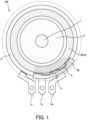
- FIG. 1 is a schematic cross-sectional view in an axial direction of a motor 100 as a rotating electrical machine according to the present embodiment.
- FIG. 2 is an enlarged view of a vicinity of a neutral point bus bar 4 of the motor 100 according to the present embodiment.
- the motor 100 is a three-phase dielectric motor mounted on a vehicle and driven by a three-phase alternating current.
- the motor 100 is used as, for example, a motor generator for driving a hybrid vehicle.
- the motor 100 includes a rotating shaft 1, a rotor 2 fixed to the rotating shaft 1, a stator core 3, and a neutral point bus bar 4.
- the motor 100 is supplied with electrical power from an inverter unit (not shown) to rotate the rotor 2, thereby rotationally driving the rotating shaft 1.
- the stator core 3 is formed in a cylindrical shape, and includes a three-phase coil 30 including a U-phase coil 31, a V-phase coil 32, and a W-phase coil 33 on a radially inner side (see FIG. 2 ).
- the three-phase coil 30 is configured by arranging the U-phase coil 31, the V-phase coil 32, and the W-phase coil 33 in this order in a circumferential direction thereof.
- the U-phase coil 31, the V-phase coil 32, and the W-phase coil 33 are formed by mutually connecting a plurality of segment coils each formed in a U shape.
- the segment coil is constituted by a conducting wire in which a periphery of a conductor having a rectangular cross section is covered with an insulating layer, that is, a so-called flat wire.
- the flat wire is a metal wire with high electrical conductivity.
- the metal wire is formed of, for example, copper, aluminum, silver, gold, or an alloy thereof.
- the insulating layer is formed of, for example, a resin coating.
- As the resin a polyamide-based resin, an epoxy-based resin, an acrylic-based resin, or a urethane-based resin can be used.
- the neutral point bus bar 4 is formed of, for example, a conductive metal plate. As shown in FIGS. 1 and 2 , the neutral point bus bar 4 is formed in an arc shape along an outer periphery of the three-phase coil 30. As shown in FIG. 2 , in the present embodiment, one end 32a of the V-phase coil 32 is connected to a vicinity of a center (connection point 4a) of the neutral point bus bar 4 in the circumferential direction, and one end 31a of the U-phase coil 31 and one end 33a of the W-phase coil 33 are connected to vicinities (connection points 4b and 4c) of ends of the neutral point bus bar 4 in the circumferential direction. The other ends 31b, 32b, 33b of the U-phase coil 31, the V-phase coil 32, and the W-phase coil 33 are respectively connected to metal terminals 7u, 7v, and 7w electrically connected to an inverter unit (not shown).
- the neutral point bus bar 4 is formed in a shape in which vicinities of the connection points 4a, 4b, and 4c protrude toward the center of the arc. With such a shape, it is possible to prevent a region R1 between the connection point 4a and the connection point 4b of the neutral point bus bar 4 and a region R2 between the connection point 4a and the connection point 4c from coming into contact with the three-phase coil 30, and it is possible to secure insulation between the three-phase coil 30 and the neutral point bus bar 4 in the regions R1 and R2.
- the motor 100 further includes a thermistor 5 as a temperature detector that detects a temperature of the three-phase coil 30.
- the thermistor 5 is provided in the vicinity of the center of the neutral point bus bar 4 (in the vicinity of the connection point 4a) so as to face a position to which the one end 32a of the V-phase coil 32 is connected.
- the thermistor 5 is attached to a recess 4d that is recessed inward in a radial direction by protruding the vicinity of the center (the vicinity of the connection point 4a) of the neutral point bus bar 4 toward the center of the arc.
- the neutral point bus bar 4 and the thermistor 5 are integrated by a molding material M.
- the thermistor 5 by attaching the thermistor 5 to the position (recess 4d) facing the connection point 4a, it is possible to measure the temperature even when the current flows between any coils of the three three-phase coils 30.
- the thermistor 5 is attached to a place other than the vicinity of the connection point 4a (recess 4d), specifically, for example, in a case where the thermistor 5 is attached to the region R1 between the connection point 4b and the connection point 4a of the neutral point bus bar 4, the temperature when the current flows between the W-phase coil 33 and the V-phase coil 32 cannot be measured.
- the motor 100 is in a locked state or in a case where a rotation speed of the motor 100 is extremely low, the current flowing through the three-phase coil 30 is large, and thus the temperature of the three-phase coil 30 increases. In such a state, in a case where it is not possible to measure the temperature when the current flows between the W-phase coil 33 and the V-phase coil 32, it is not possible to execute appropriate control, and the motor 100 may be damaged.
- the thermistor 5 is attached to the above position. Accordingly, the temperature of the three-phase coil 30 can be accurately measured regardless of the current flowing between any coils of the three three-phase coils 30, and the motor 100 can be appropriately controlled.
- the neutral point bus bar 4 and the thermistor 5 are integrated by the molding material M.
- a method of integrating the neutral point bus bar 4 and the thermistor 5 will be described.
- the neutral point bus bar 4 and the thermistor 5 are integrated by molding. Specifically, as shown in FIG. 3A , the neutral point bus bar 4 and the thermistor 5 are set in a cavity C of a mold 6 formed by an upper mold 6A and a lower mold 6B. At this time, the neutral point bus bar 4 and the thermistor 5 are clamped by ejector pins 60a and 60b provided in the upper mold 6A and the lower mold 6B so as to maintain a state in which the neutral point bus bar 4 and the thermistor 5 are in contact with each other. Pins 6C and 6D shown in FIGS.
- 3A and 3B are pins for forming a through hole 8a through which a connection portion between the other end 32b of the V-phase coil 32 and the terminal 7v is inserted and a through hole 8b through which a connection portion between the other end 31b of the U-phase coil 31 and the terminal 7u is inserted, respectively.
- the adhesive is interposed between the thermistor 5 and the neutral point bus bar 4, and the temperature detection accuracy of the thermistor 5 may deteriorate.
- the neutral point bus bar 4 and the thermistor 5 are molded while being clamped by the ejector pins 60a and 60b so as to maintain a state in which the neutral point bus bar 4 and the thermistor 5 are in contact with each other, and thus the neutral point bus bar 4 and the thermistor 5 are integrated so as to be in direct contact with each other. Accordingly, since no adhesive is interposed between the thermistor 5 and the neutral point bus bar 4, the temperature of the thermistor 5 can be accurately detected.
- the motor 100 (rotating electrical machine) includes the three-phase coil 30 including the U-phase coil 31, the V-phase coil 32, and the W-phase coil 33 each formed of the flat wire, the neutral point bus bar 4 that forms a neutral point of the three-phase coil 30 and is formed of a conductive plate, and the thermistor 5 (temperature detector) that detects a temperature of the three-phase coil 30.
- the neutral point bus bar 4 is formed in an arc shape along the outer periphery of the three-phase coil 30, the one end 32a of the V-phase coil 32 in the three-phase coil 30 is connected to the vicinity of the center (connection point 4a) of the neutral point bus bar 4 in the circumferential direction, and each of the one end 31a of the U-phase coil 31 and the one end 33a of the W-phase coil 33 in the three-phase coil 30 is connected to a vicinity of an end of the neutral point bus bar 4 in the circumferential direction.
- the thermistor 5 (temperature detector) is attached to a position facing the one end 32a of the V-phase coil 32 near the center of the neutral point bus bar 4.
- the neutral point bus bar 4 has the recess 4d recessed radially inward, and the thermistor 5 (temperature detector) is provided in the recess 4d.
- the neutral point bus bar 4 and the thermistor 5 are integrated by the molding material M.
- the neutral point bus bar 4 and the thermistor 5 are integrated, the work of fixing the thermistor 5 (temperature detector) to the neutral point bus bar 4 with an adhesive or the like can be omitted. Accordingly, the work efficiency at the time of assembling the motor 100 (rotating electrical machine) can be improved. Since the adhesive or the like is not interposed between the thermistor 5 (temperature detector) and the neutral point bus bar 4, it is possible to prevent the temperature detection accuracy of the thermistor 5 from deteriorating.
- the neutral point bus bar 4 and the thermistor 5 are molded while being clamped by the ejector pins 60a and 60b provided on the upper mold 6A and the lower mold 6B so as to maintain a state in which the neutral point bus bar 4 and the thermistor 5 (temperature detector) are in contact with each other.
- the neutral point bus bar 4 and the thermistor 5 (temperature detector) integrated by molding are attached to the three-phase coil 30.
- the neutral point bus bar 4 and the thermistor 5 are integrated in direct contact with each other. Accordingly, since the adhesive is not interposed between the thermistor 5 and the neutral point bus bar 4, it is possible to prevent the temperature detection accuracy of the thermistor 5 from deteriorating. In addition, since it is not necessary to separately provide a support pin or the like in the mold 6 at the time of integration, it is possible to prevent an increase in cost and complication of a structure of the mold 6. Further, since the neutral point bus bar 4 and the thermistor 5 (temperature detector) are integrally attached to the three-phase coil 30, it is possible to improve work efficiency at the time of assembling the motor 100 (rotating electrical machine).
- the motor 100 is not limited to a motor mounted on a vehicle.
- the configuration related to the neutral point bus bar 4 can also be applied to a generator.
- the case where the one end 32a of the V-phase coil 32 is connected to the vicinity of the center (connection point 4a) of the neutral point bus bar 4 has been described as an example, but the present invention is not limited thereto.
- the one end 31a of the U-phase coil 31 or the one end 33a of the W-phase coil 33 may be connected to the vicinity of the center (connection point 4a) of the neutral point bus bar 4.
- the temperature detector 5 has been described as an example of the temperature detector in the above embodiment, the temperature detector is not limited thereto, and may be another type of temperature detector (thermocouple, platinum resistance thermometer, or the like).
- the regions R1 and R2 may not bulge outward in the radial direction as long as the insulation is ensured.
- the case where the other ends 31b and 32b of the U-phase coil 31 and the V-phase coil 32 are surrounded by the molding material M has been described as an example, but the present invention is not limited thereto.
- the other end 33b of the W-phase coil 33 may also be surrounded by the molding material.
Landscapes
- Engineering & Computer Science (AREA)
- Power Engineering (AREA)
- Microelectronics & Electronic Packaging (AREA)
- Manufacturing & Machinery (AREA)
Applications Claiming Priority (1)
| Application Number | Priority Date | Filing Date | Title |
|---|---|---|---|
| PCT/JP2021/018690 WO2022244083A1 (ja) | 2021-05-17 | 2021-05-17 | 回転電機及び回転電機の製造方法 |
Publications (3)
| Publication Number | Publication Date |
|---|---|
| EP4344033A1 EP4344033A1 (en) | 2024-03-27 |
| EP4344033A4 EP4344033A4 (en) | 2024-07-17 |
| EP4344033B1 true EP4344033B1 (en) | 2025-03-12 |
Family
ID=84141377
Family Applications (1)
| Application Number | Title | Priority Date | Filing Date |
|---|---|---|---|
| EP21940025.6A Active EP4344033B1 (en) | 2021-05-17 | 2021-05-17 | Rotating electrical machine and method for manufacturing rotating electrical machine |
Country Status (5)
| Country | Link |
|---|---|
| US (1) | US12562625B2 (https=) |
| EP (1) | EP4344033B1 (https=) |
| JP (1) | JP7556462B2 (https=) |
| CN (1) | CN117280579A (https=) |
| WO (1) | WO2022244083A1 (https=) |
Family Cites Families (9)
| Publication number | Priority date | Publication date | Assignee | Title |
|---|---|---|---|---|
| JP4716130B2 (ja) * | 2006-11-22 | 2011-07-06 | 株式会社デンソー | 回転電機の固定子 |
| JP4751942B2 (ja) * | 2009-06-17 | 2011-08-17 | アイシン精機株式会社 | ステータ |
| JP2013219913A (ja) * | 2012-04-09 | 2013-10-24 | Toyota Motor Corp | 回転電機 |
| JP5621810B2 (ja) | 2012-04-11 | 2014-11-12 | トヨタ自動車株式会社 | 回転電機 |
| JP5996917B2 (ja) | 2012-04-20 | 2016-09-21 | トヨタ自動車株式会社 | 回転電機用ステータ及びその回転電機用ステータの製造方法 |
| JP6281499B2 (ja) * | 2015-01-09 | 2018-02-21 | トヨタ自動車株式会社 | 回転電機用ステータ |
| JP6729419B2 (ja) * | 2017-01-23 | 2020-07-22 | トヨタ自動車株式会社 | 回転電機のステータ |
| JP2019047661A (ja) | 2017-09-05 | 2019-03-22 | 株式会社デンソー | 回転電機 |
| DE102019121189A1 (de) * | 2019-04-26 | 2020-10-29 | Schaeffler Technologies AG & Co. KG | Elektrische Maschine |
-
2021
- 2021-05-17 EP EP21940025.6A patent/EP4344033B1/en active Active
- 2021-05-17 CN CN202180097990.3A patent/CN117280579A/zh active Pending
- 2021-05-17 WO PCT/JP2021/018690 patent/WO2022244083A1/ja not_active Ceased
- 2021-05-17 US US18/561,550 patent/US12562625B2/en active Active
- 2021-05-17 JP JP2023522028A patent/JP7556462B2/ja active Active
Also Published As
| Publication number | Publication date |
|---|---|
| CN117280579A (zh) | 2023-12-22 |
| EP4344033A4 (en) | 2024-07-17 |
| US20240235334A1 (en) | 2024-07-11 |
| JP7556462B2 (ja) | 2024-09-27 |
| EP4344033A1 (en) | 2024-03-27 |
| US12562625B2 (en) | 2026-02-24 |
| JPWO2022244083A1 (https=) | 2022-11-24 |
| WO2022244083A1 (ja) | 2022-11-24 |
Similar Documents
| Publication | Publication Date | Title |
|---|---|---|
| JP2019110676A (ja) | 回転電機のステータ | |
| US20130270973A1 (en) | Rotary electric machine | |
| US9143021B2 (en) | Dynamo-electric machine | |
| US10199898B2 (en) | Rotary electric machine stator having a resin molded portion | |
| US9664498B2 (en) | Variable reluctance resolver | |
| US11404928B2 (en) | Stator, method for manufacturing stator, coil, and method for manufacturing coil | |
| CN110212674B (zh) | 马达 | |
| JP7006675B2 (ja) | モータ | |
| JP2010041898A (ja) | 電動パワーステアリング装置用モータ | |
| CN216564710U (zh) | 用于电机的母排单元 | |
| US20220320970A1 (en) | Stator unit and motor | |
| US11901848B2 (en) | Rotating electric machine and armature | |
| JP2013158078A (ja) | 回転電機のステータ | |
| US12212206B2 (en) | Busbar module for rotating electric machine | |
| JP5181246B2 (ja) | レゾルバのステータ構造及びレゾルバ | |
| EP4344033B1 (en) | Rotating electrical machine and method for manufacturing rotating electrical machine | |
| JP2021182801A (ja) | 車両用回転電機のステータ | |
| CN112910147A (zh) | 定子、马达及定子的制造方法 | |
| JP7329653B1 (ja) | ステータ及びそれを用いた回転電機 | |
| CN118282138A (zh) | 汇流排组件和电驱动总成系统 | |
| JP7450705B2 (ja) | 回転電機の固定子及び回転電機 | |
| JP2023010348A (ja) | 配線部品 | |
| US20250175040A1 (en) | Motor | |
| JP2022144595A (ja) | 回転電機 | |
| CN107478939B (zh) | 电机的定子绕组对称性检测方法和检测装置 |
Legal Events
| Date | Code | Title | Description |
|---|---|---|---|
| STAA | Information on the status of an ep patent application or granted ep patent |
Free format text: STATUS: UNKNOWN |
|
| STAA | Information on the status of an ep patent application or granted ep patent |
Free format text: STATUS: THE INTERNATIONAL PUBLICATION HAS BEEN MADE |
|
| PUAI | Public reference made under article 153(3) epc to a published international application that has entered the european phase |
Free format text: ORIGINAL CODE: 0009012 |
|
| STAA | Information on the status of an ep patent application or granted ep patent |
Free format text: STATUS: REQUEST FOR EXAMINATION WAS MADE |
|
| 17P | Request for examination filed |
Effective date: 20231117 |
|
| AK | Designated contracting states |
Kind code of ref document: A1 Designated state(s): AL AT BE BG CH CY CZ DE DK EE ES FI FR GB GR HR HU IE IS IT LI LT LU LV MC MK MT NL NO PL PT RO RS SE SI SK SM TR |
|
| A4 | Supplementary search report drawn up and despatched |
Effective date: 20240618 |
|
| RIC1 | Information provided on ipc code assigned before grant |
Ipc: H02K 11/25 20160101AFI20240612BHEP |
|
| DAV | Request for validation of the european patent (deleted) | ||
| DAX | Request for extension of the european patent (deleted) | ||
| GRAP | Despatch of communication of intention to grant a patent |
Free format text: ORIGINAL CODE: EPIDOSNIGR1 |
|
| STAA | Information on the status of an ep patent application or granted ep patent |
Free format text: STATUS: GRANT OF PATENT IS INTENDED |
|
| INTG | Intention to grant announced |
Effective date: 20241219 |
|
| GRAS | Grant fee paid |
Free format text: ORIGINAL CODE: EPIDOSNIGR3 |
|
| GRAA | (expected) grant |
Free format text: ORIGINAL CODE: 0009210 |
|
| STAA | Information on the status of an ep patent application or granted ep patent |
Free format text: STATUS: THE PATENT HAS BEEN GRANTED |
|
| AK | Designated contracting states |
Kind code of ref document: B1 Designated state(s): AL AT BE BG CH CY CZ DE DK EE ES FI FR GB GR HR HU IE IS IT LI LT LU LV MC MK MT NL NO PL PT RO RS SE SI SK SM TR |
|
| REG | Reference to a national code |
Ref country code: GB Ref legal event code: FG4D |
|
| REG | Reference to a national code |
Ref country code: CH Ref legal event code: EP |
|
| REG | Reference to a national code |
Ref country code: DE Ref legal event code: R096 Ref document number: 602021027671 Country of ref document: DE |
|
| REG | Reference to a national code |
Ref country code: IE Ref legal event code: FG4D |
|
| PG25 | Lapsed in a contracting state [announced via postgrant information from national office to epo] |
Ref country code: RS Free format text: LAPSE BECAUSE OF FAILURE TO SUBMIT A TRANSLATION OF THE DESCRIPTION OR TO PAY THE FEE WITHIN THE PRESCRIBED TIME-LIMIT Effective date: 20250612 |
|
| PG25 | Lapsed in a contracting state [announced via postgrant information from national office to epo] |
Ref country code: FI Free format text: LAPSE BECAUSE OF FAILURE TO SUBMIT A TRANSLATION OF THE DESCRIPTION OR TO PAY THE FEE WITHIN THE PRESCRIBED TIME-LIMIT Effective date: 20250312 |
|
| PGFP | Annual fee paid to national office [announced via postgrant information from national office to epo] |
Ref country code: DE Payment date: 20250520 Year of fee payment: 5 |
|
| PG25 | Lapsed in a contracting state [announced via postgrant information from national office to epo] |
Ref country code: ES Free format text: LAPSE BECAUSE OF FAILURE TO SUBMIT A TRANSLATION OF THE DESCRIPTION OR TO PAY THE FEE WITHIN THE PRESCRIBED TIME-LIMIT Effective date: 20250312 |
|
| REG | Reference to a national code |
Ref country code: LT Ref legal event code: MG9D |
|
| PG25 | Lapsed in a contracting state [announced via postgrant information from national office to epo] |
Ref country code: NO Free format text: LAPSE BECAUSE OF FAILURE TO SUBMIT A TRANSLATION OF THE DESCRIPTION OR TO PAY THE FEE WITHIN THE PRESCRIBED TIME-LIMIT Effective date: 20250612 |
|
| PG25 | Lapsed in a contracting state [announced via postgrant information from national office to epo] |
Ref country code: HR Free format text: LAPSE BECAUSE OF FAILURE TO SUBMIT A TRANSLATION OF THE DESCRIPTION OR TO PAY THE FEE WITHIN THE PRESCRIBED TIME-LIMIT Effective date: 20250312 |
|
| REG | Reference to a national code |
Ref country code: NL Ref legal event code: MP Effective date: 20250312 |
|
| PG25 | Lapsed in a contracting state [announced via postgrant information from national office to epo] |
Ref country code: LV Free format text: LAPSE BECAUSE OF FAILURE TO SUBMIT A TRANSLATION OF THE DESCRIPTION OR TO PAY THE FEE WITHIN THE PRESCRIBED TIME-LIMIT Effective date: 20250312 |
|
| PGFP | Annual fee paid to national office [announced via postgrant information from national office to epo] |
Ref country code: FR Payment date: 20250521 Year of fee payment: 5 |
|
| PG25 | Lapsed in a contracting state [announced via postgrant information from national office to epo] |
Ref country code: BG Free format text: LAPSE BECAUSE OF FAILURE TO SUBMIT A TRANSLATION OF THE DESCRIPTION OR TO PAY THE FEE WITHIN THE PRESCRIBED TIME-LIMIT Effective date: 20250312 Ref country code: GR Free format text: LAPSE BECAUSE OF FAILURE TO SUBMIT A TRANSLATION OF THE DESCRIPTION OR TO PAY THE FEE WITHIN THE PRESCRIBED TIME-LIMIT Effective date: 20250613 |
|
| REG | Reference to a national code |
Ref country code: AT Ref legal event code: MK05 Ref document number: 1775859 Country of ref document: AT Kind code of ref document: T Effective date: 20250312 |
|
| PG25 | Lapsed in a contracting state [announced via postgrant information from national office to epo] |
Ref country code: NL Free format text: LAPSE BECAUSE OF FAILURE TO SUBMIT A TRANSLATION OF THE DESCRIPTION OR TO PAY THE FEE WITHIN THE PRESCRIBED TIME-LIMIT Effective date: 20250312 |
|
| PG25 | Lapsed in a contracting state [announced via postgrant information from national office to epo] |
Ref country code: SE Free format text: LAPSE BECAUSE OF FAILURE TO SUBMIT A TRANSLATION OF THE DESCRIPTION OR TO PAY THE FEE WITHIN THE PRESCRIBED TIME-LIMIT Effective date: 20250312 |
|
| PG25 | Lapsed in a contracting state [announced via postgrant information from national office to epo] |
Ref country code: SM Free format text: LAPSE BECAUSE OF FAILURE TO SUBMIT A TRANSLATION OF THE DESCRIPTION OR TO PAY THE FEE WITHIN THE PRESCRIBED TIME-LIMIT Effective date: 20250312 |
|
| PG25 | Lapsed in a contracting state [announced via postgrant information from national office to epo] |
Ref country code: PT Free format text: LAPSE BECAUSE OF FAILURE TO SUBMIT A TRANSLATION OF THE DESCRIPTION OR TO PAY THE FEE WITHIN THE PRESCRIBED TIME-LIMIT Effective date: 20250714 |
|
| PG25 | Lapsed in a contracting state [announced via postgrant information from national office to epo] |
Ref country code: IT Free format text: LAPSE BECAUSE OF FAILURE TO SUBMIT A TRANSLATION OF THE DESCRIPTION OR TO PAY THE FEE WITHIN THE PRESCRIBED TIME-LIMIT Effective date: 20250312 Ref country code: PL Free format text: LAPSE BECAUSE OF FAILURE TO SUBMIT A TRANSLATION OF THE DESCRIPTION OR TO PAY THE FEE WITHIN THE PRESCRIBED TIME-LIMIT Effective date: 20250312 |
|
| PG25 | Lapsed in a contracting state [announced via postgrant information from national office to epo] |
Ref country code: AT Free format text: LAPSE BECAUSE OF FAILURE TO SUBMIT A TRANSLATION OF THE DESCRIPTION OR TO PAY THE FEE WITHIN THE PRESCRIBED TIME-LIMIT Effective date: 20250312 |
|
| PG25 | Lapsed in a contracting state [announced via postgrant information from national office to epo] |
Ref country code: EE Free format text: LAPSE BECAUSE OF FAILURE TO SUBMIT A TRANSLATION OF THE DESCRIPTION OR TO PAY THE FEE WITHIN THE PRESCRIBED TIME-LIMIT Effective date: 20250312 Ref country code: CZ Free format text: LAPSE BECAUSE OF FAILURE TO SUBMIT A TRANSLATION OF THE DESCRIPTION OR TO PAY THE FEE WITHIN THE PRESCRIBED TIME-LIMIT Effective date: 20250312 |
|
| PG25 | Lapsed in a contracting state [announced via postgrant information from national office to epo] |
Ref country code: RO Free format text: LAPSE BECAUSE OF FAILURE TO SUBMIT A TRANSLATION OF THE DESCRIPTION OR TO PAY THE FEE WITHIN THE PRESCRIBED TIME-LIMIT Effective date: 20250312 |
|
| PG25 | Lapsed in a contracting state [announced via postgrant information from national office to epo] |
Ref country code: SK Free format text: LAPSE BECAUSE OF FAILURE TO SUBMIT A TRANSLATION OF THE DESCRIPTION OR TO PAY THE FEE WITHIN THE PRESCRIBED TIME-LIMIT Effective date: 20250312 |
|
| PG25 | Lapsed in a contracting state [announced via postgrant information from national office to epo] |
Ref country code: IS Free format text: LAPSE BECAUSE OF FAILURE TO SUBMIT A TRANSLATION OF THE DESCRIPTION OR TO PAY THE FEE WITHIN THE PRESCRIBED TIME-LIMIT Effective date: 20250712 |
|
| REG | Reference to a national code |
Ref country code: DE Ref legal event code: R097 Ref document number: 602021027671 Country of ref document: DE |
|
| REG | Reference to a national code |
Ref country code: CH Ref legal event code: H13 Free format text: ST27 STATUS EVENT CODE: U-0-0-H10-H13 (AS PROVIDED BY THE NATIONAL OFFICE) Effective date: 20251223 |
|
| PG25 | Lapsed in a contracting state [announced via postgrant information from national office to epo] |
Ref country code: DK Free format text: LAPSE BECAUSE OF FAILURE TO SUBMIT A TRANSLATION OF THE DESCRIPTION OR TO PAY THE FEE WITHIN THE PRESCRIBED TIME-LIMIT Effective date: 20250312 |
|
| PG25 | Lapsed in a contracting state [announced via postgrant information from national office to epo] |
Ref country code: LU Free format text: LAPSE BECAUSE OF NON-PAYMENT OF DUE FEES Effective date: 20250517 |
|
| PLBE | No opposition filed within time limit |
Free format text: ORIGINAL CODE: 0009261 |
|
| STAA | Information on the status of an ep patent application or granted ep patent |
Free format text: STATUS: NO OPPOSITION FILED WITHIN TIME LIMIT |
|
| PG25 | Lapsed in a contracting state [announced via postgrant information from national office to epo] |
Ref country code: CH Free format text: LAPSE BECAUSE OF NON-PAYMENT OF DUE FEES Effective date: 20250531 |
|
| REG | Reference to a national code |
Ref country code: CH Ref legal event code: L10 Free format text: ST27 STATUS EVENT CODE: U-0-0-L10-L00 (AS PROVIDED BY THE NATIONAL OFFICE) Effective date: 20260121 |
|
| REG | Reference to a national code |
Ref country code: BE Ref legal event code: MM Effective date: 20250531 |
|
| PG25 | Lapsed in a contracting state [announced via postgrant information from national office to epo] |
Ref country code: MC Free format text: LAPSE BECAUSE OF FAILURE TO SUBMIT A TRANSLATION OF THE DESCRIPTION OR TO PAY THE FEE WITHIN THE PRESCRIBED TIME-LIMIT Effective date: 20250312 |
|
| 26N | No opposition filed |
Effective date: 20251215 |
|
| PGFP | Annual fee paid to national office [announced via postgrant information from national office to epo] |
Ref country code: GB Payment date: 20260317 Year of fee payment: 6 |
|
| PG25 | Lapsed in a contracting state [announced via postgrant information from national office to epo] |
Ref country code: IE Free format text: LAPSE BECAUSE OF NON-PAYMENT OF DUE FEES Effective date: 20250517 |
|
| PG25 | Lapsed in a contracting state [announced via postgrant information from national office to epo] |
Ref country code: BE Free format text: LAPSE BECAUSE OF NON-PAYMENT OF DUE FEES Effective date: 20250531 |