EP4280397B1 - Cadre de retenue pour connecteur à fiche - Google Patents
Cadre de retenue pour connecteur à fiche Download PDFInfo
- Publication number
- EP4280397B1 EP4280397B1 EP23172202.6A EP23172202A EP4280397B1 EP 4280397 B1 EP4280397 B1 EP 4280397B1 EP 23172202 A EP23172202 A EP 23172202A EP 4280397 B1 EP4280397 B1 EP 4280397B1
- Authority
- EP
- European Patent Office
- Prior art keywords
- base portion
- deformation portion
- frame
- base
- holding frame
- Prior art date
- Legal status (The legal status is an assumption and is not a legal conclusion. Google has not performed a legal analysis and makes no representation as to the accuracy of the status listed.)
- Active
Links
Images


Classifications
-
- H—ELECTRICITY
- H01—ELECTRIC ELEMENTS
- H01R—ELECTRICALLY-CONDUCTIVE CONNECTIONS; STRUCTURAL ASSOCIATIONS OF A PLURALITY OF MUTUALLY-INSULATED ELECTRICAL CONNECTING ELEMENTS; COUPLING DEVICES; CURRENT COLLECTORS
- H01R43/00—Apparatus or processes specially adapted for manufacturing, assembling, maintaining, or repairing of line connectors or current collectors or for joining electric conductors
- H01R43/20—Apparatus or processes specially adapted for manufacturing, assembling, maintaining, or repairing of line connectors or current collectors or for joining electric conductors for assembling or disassembling contact members with insulating base, case or sleeve
-
- H—ELECTRICITY
- H01—ELECTRIC ELEMENTS
- H01R—ELECTRICALLY-CONDUCTIVE CONNECTIONS; STRUCTURAL ASSOCIATIONS OF A PLURALITY OF MUTUALLY-INSULATED ELECTRICAL CONNECTING ELEMENTS; COUPLING DEVICES; CURRENT COLLECTORS
- H01R13/00—Details of coupling devices of the kinds covered by groups H01R12/70 or H01R24/00 - H01R33/00
- H01R13/46—Bases; Cases
- H01R13/502—Bases; Cases composed of different pieces
- H01R13/5025—Bases; Cases composed of different pieces one or more pieces being of resilient material
-
- H—ELECTRICITY
- H01—ELECTRIC ELEMENTS
- H01R—ELECTRICALLY-CONDUCTIVE CONNECTIONS; STRUCTURAL ASSOCIATIONS OF A PLURALITY OF MUTUALLY-INSULATED ELECTRICAL CONNECTING ELEMENTS; COUPLING DEVICES; CURRENT COLLECTORS
- H01R13/00—Details of coupling devices of the kinds covered by groups H01R12/70 or H01R24/00 - H01R33/00
- H01R13/46—Bases; Cases
- H01R13/502—Bases; Cases composed of different pieces
- H01R13/506—Bases; Cases composed of different pieces assembled by snap action of the parts
-
- H—ELECTRICITY
- H01—ELECTRIC ELEMENTS
- H01R—ELECTRICALLY-CONDUCTIVE CONNECTIONS; STRUCTURAL ASSOCIATIONS OF A PLURALITY OF MUTUALLY-INSULATED ELECTRICAL CONNECTING ELEMENTS; COUPLING DEVICES; CURRENT COLLECTORS
- H01R13/00—Details of coupling devices of the kinds covered by groups H01R12/70 or H01R24/00 - H01R33/00
- H01R13/46—Bases; Cases
- H01R13/514—Bases; Cases composed as a modular blocks or assembly, i.e. composed of co-operating parts provided with contact members or holding contact members between them
-
- H—ELECTRICITY
- H01—ELECTRIC ELEMENTS
- H01R—ELECTRICALLY-CONDUCTIVE CONNECTIONS; STRUCTURAL ASSOCIATIONS OF A PLURALITY OF MUTUALLY-INSULATED ELECTRICAL CONNECTING ELEMENTS; COUPLING DEVICES; CURRENT COLLECTORS
- H01R13/00—Details of coupling devices of the kinds covered by groups H01R12/70 or H01R24/00 - H01R33/00
- H01R13/46—Bases; Cases
- H01R13/516—Means for holding or embracing insulating body, e.g. casing, hoods
- H01R13/518—Means for holding or embracing insulating body, e.g. casing, hoods for holding or embracing several coupling parts, e.g. frames
-
- H—ELECTRICITY
- H01—ELECTRIC ELEMENTS
- H01R—ELECTRICALLY-CONDUCTIVE CONNECTIONS; STRUCTURAL ASSOCIATIONS OF A PLURALITY OF MUTUALLY-INSULATED ELECTRICAL CONNECTING ELEMENTS; COUPLING DEVICES; CURRENT COLLECTORS
- H01R13/00—Details of coupling devices of the kinds covered by groups H01R12/70 or H01R24/00 - H01R33/00
- H01R13/62—Means for facilitating engagement or disengagement of coupling parts or for holding them in engagement
- H01R13/627—Snap or like fastening
- H01R13/6275—Latching arms not integral with the housing
-
- H—ELECTRICITY
- H01—ELECTRIC ELEMENTS
- H01R—ELECTRICALLY-CONDUCTIVE CONNECTIONS; STRUCTURAL ASSOCIATIONS OF A PLURALITY OF MUTUALLY-INSULATED ELECTRICAL CONNECTING ELEMENTS; COUPLING DEVICES; CURRENT COLLECTORS
- H01R13/00—Details of coupling devices of the kinds covered by groups H01R12/70 or H01R24/00 - H01R33/00
- H01R13/62—Means for facilitating engagement or disengagement of coupling parts or for holding them in engagement
- H01R13/629—Additional means for facilitating engagement or disengagement of coupling parts, e.g. aligning or guiding means, levers, gas pressure electrical locking indicators, manufacturing tolerances
-
- H—ELECTRICITY
- H01—ELECTRIC ELEMENTS
- H01R—ELECTRICALLY-CONDUCTIVE CONNECTIONS; STRUCTURAL ASSOCIATIONS OF A PLURALITY OF MUTUALLY-INSULATED ELECTRICAL CONNECTING ELEMENTS; COUPLING DEVICES; CURRENT COLLECTORS
- H01R13/00—Details of coupling devices of the kinds covered by groups H01R12/70 or H01R24/00 - H01R33/00
- H01R13/62—Means for facilitating engagement or disengagement of coupling parts or for holding them in engagement
- H01R13/639—Additional means for holding or locking coupling parts together, after engagement, e.g. separate keylock, retainer strap
-
- H—ELECTRICITY
- H01—ELECTRIC ELEMENTS
- H01R—ELECTRICALLY-CONDUCTIVE CONNECTIONS; STRUCTURAL ASSOCIATIONS OF A PLURALITY OF MUTUALLY-INSULATED ELECTRICAL CONNECTING ELEMENTS; COUPLING DEVICES; CURRENT COLLECTORS
- H01R13/00—Details of coupling devices of the kinds covered by groups H01R12/70 or H01R24/00 - H01R33/00
- H01R13/648—Protective earth or shield arrangements on coupling devices, e.g. anti-static shielding
- H01R13/652—Protective earth or shield arrangements on coupling devices, e.g. anti-static shielding with earth pin, blade or socket
-
- H—ELECTRICITY
- H01—ELECTRIC ELEMENTS
- H01R—ELECTRICALLY-CONDUCTIVE CONNECTIONS; STRUCTURAL ASSOCIATIONS OF A PLURALITY OF MUTUALLY-INSULATED ELECTRICAL CONNECTING ELEMENTS; COUPLING DEVICES; CURRENT COLLECTORS
- H01R43/00—Apparatus or processes specially adapted for manufacturing, assembling, maintaining, or repairing of line connectors or current collectors or for joining electric conductors
- H01R43/18—Apparatus or processes specially adapted for manufacturing, assembling, maintaining, or repairing of line connectors or current collectors or for joining electric conductors for manufacturing bases or cases for contact members
-
- H—ELECTRICITY
- H01—ELECTRIC ELEMENTS
- H01R—ELECTRICALLY-CONDUCTIVE CONNECTIONS; STRUCTURAL ASSOCIATIONS OF A PLURALITY OF MUTUALLY-INSULATED ELECTRICAL CONNECTING ELEMENTS; COUPLING DEVICES; CURRENT COLLECTORS
- H01R43/00—Apparatus or processes specially adapted for manufacturing, assembling, maintaining, or repairing of line connectors or current collectors or for joining electric conductors
- H01R43/20—Apparatus or processes specially adapted for manufacturing, assembling, maintaining, or repairing of line connectors or current collectors or for joining electric conductors for assembling or disassembling contact members with insulating base, case or sleeve
- H01R43/22—Hand tools
-
- H—ELECTRICITY
- H01—ELECTRIC ELEMENTS
- H01R—ELECTRICALLY-CONDUCTIVE CONNECTIONS; STRUCTURAL ASSOCIATIONS OF A PLURALITY OF MUTUALLY-INSULATED ELECTRICAL CONNECTING ELEMENTS; COUPLING DEVICES; CURRENT COLLECTORS
- H01R12/00—Structural associations of a plurality of mutually-insulated electrical connecting elements, specially adapted for printed circuits, e.g. printed circuit boards [PCB], flat or ribbon cables, or like generally planar structures, e.g. terminal strips, terminal blocks; Coupling devices specially adapted for printed circuits, flat or ribbon cables, or like generally planar structures; Terminals specially adapted for contact with, or insertion into, printed circuits, flat or ribbon cables, or like generally planar structures
- H01R12/70—Coupling devices
- H01R12/7005—Guiding, mounting, polarizing or locking means; Extractors
- H01R12/7011—Locking or fixing a connector to a PCB
-
- H—ELECTRICITY
- H01—ELECTRIC ELEMENTS
- H01R—ELECTRICALLY-CONDUCTIVE CONNECTIONS; STRUCTURAL ASSOCIATIONS OF A PLURALITY OF MUTUALLY-INSULATED ELECTRICAL CONNECTING ELEMENTS; COUPLING DEVICES; CURRENT COLLECTORS
- H01R12/00—Structural associations of a plurality of mutually-insulated electrical connecting elements, specially adapted for printed circuits, e.g. printed circuit boards [PCB], flat or ribbon cables, or like generally planar structures, e.g. terminal strips, terminal blocks; Coupling devices specially adapted for printed circuits, flat or ribbon cables, or like generally planar structures; Terminals specially adapted for contact with, or insertion into, printed circuits, flat or ribbon cables, or like generally planar structures
- H01R12/70—Coupling devices
- H01R12/91—Coupling devices allowing relative movement between coupling parts, e.g. floating or self aligning
-
- H—ELECTRICITY
- H01—ELECTRIC ELEMENTS
- H01R—ELECTRICALLY-CONDUCTIVE CONNECTIONS; STRUCTURAL ASSOCIATIONS OF A PLURALITY OF MUTUALLY-INSULATED ELECTRICAL CONNECTING ELEMENTS; COUPLING DEVICES; CURRENT COLLECTORS
- H01R24/00—Two-part coupling devices, or either of their cooperating parts, characterised by their overall structure
- H01R24/60—Contacts spaced along planar side wall transverse to longitudinal axis of engagement
- H01R24/62—Sliding engagements with one side only, e.g. modular jack coupling devices
-
- H—ELECTRICITY
- H01—ELECTRIC ELEMENTS
- H01R—ELECTRICALLY-CONDUCTIVE CONNECTIONS; STRUCTURAL ASSOCIATIONS OF A PLURALITY OF MUTUALLY-INSULATED ELECTRICAL CONNECTING ELEMENTS; COUPLING DEVICES; CURRENT COLLECTORS
- H01R4/00—Electrically-conductive connections between two or more conductive members in direct contact, i.e. touching one another; Means for effecting or maintaining such contact; Electrically-conductive connections having two or more spaced connecting locations for conductors and using contact members penetrating insulation
- H01R4/26—Connections in which at least one of the connecting parts has projections which bite into or engage the other connecting part in order to improve the contact
-
- H—ELECTRICITY
- H01—ELECTRIC ELEMENTS
- H01R—ELECTRICALLY-CONDUCTIVE CONNECTIONS; STRUCTURAL ASSOCIATIONS OF A PLURALITY OF MUTUALLY-INSULATED ELECTRICAL CONNECTING ELEMENTS; COUPLING DEVICES; CURRENT COLLECTORS
- H01R9/00—Structural associations of a plurality of mutually-insulated electrical connecting elements, e.g. terminal strips or terminal blocks; Terminals or binding posts mounted upon a base or in a case; Bases therefor
- H01R9/16—Fastening of connecting parts to base or case; Insulating connecting parts from base or case
-
- H—ELECTRICITY
- H01—ELECTRIC ELEMENTS
- H01R—ELECTRICALLY-CONDUCTIVE CONNECTIONS; STRUCTURAL ASSOCIATIONS OF A PLURALITY OF MUTUALLY-INSULATED ELECTRICAL CONNECTING ELEMENTS; COUPLING DEVICES; CURRENT COLLECTORS
- H01R9/00—Structural associations of a plurality of mutually-insulated electrical connecting elements, e.g. terminal strips or terminal blocks; Terminals or binding posts mounted upon a base or in a case; Bases therefor
- H01R9/22—Bases, e.g. strip, block, panel
- H01R9/226—Bases, e.g. strip, block, panel comprising a plurality of conductive flat strips providing connection between wires or components
-
- Y—GENERAL TAGGING OF NEW TECHNOLOGICAL DEVELOPMENTS; GENERAL TAGGING OF CROSS-SECTIONAL TECHNOLOGIES SPANNING OVER SEVERAL SECTIONS OF THE IPC; TECHNICAL SUBJECTS COVERED BY FORMER USPC CROSS-REFERENCE ART COLLECTIONS [XRACs] AND DIGESTS
- Y10—TECHNICAL SUBJECTS COVERED BY FORMER USPC
- Y10T—TECHNICAL SUBJECTS COVERED BY FORMER US CLASSIFICATION
- Y10T29/00—Metal working
- Y10T29/49—Method of mechanical manufacture
- Y10T29/49002—Electrical device making
- Y10T29/49117—Conductor or circuit manufacturing
- Y10T29/49124—On flat or curved insulated base, e.g., printed circuit, etc.
- Y10T29/4913—Assembling to base an electrical component, e.g., capacitor, etc.
- Y10T29/49133—Assembling to base an electrical component, e.g., capacitor, etc. with component orienting
- Y10T29/49137—Different components
-
- Y—GENERAL TAGGING OF NEW TECHNOLOGICAL DEVELOPMENTS; GENERAL TAGGING OF CROSS-SECTIONAL TECHNOLOGIES SPANNING OVER SEVERAL SECTIONS OF THE IPC; TECHNICAL SUBJECTS COVERED BY FORMER USPC CROSS-REFERENCE ART COLLECTIONS [XRACs] AND DIGESTS
- Y10—TECHNICAL SUBJECTS COVERED BY FORMER USPC
- Y10T—TECHNICAL SUBJECTS COVERED BY FORMER US CLASSIFICATION
- Y10T29/00—Metal working
- Y10T29/49—Method of mechanical manufacture
- Y10T29/49002—Electrical device making
- Y10T29/49117—Conductor or circuit manufacturing
- Y10T29/49169—Assembling electrical component directly to terminal or elongated conductor
-
- Y—GENERAL TAGGING OF NEW TECHNOLOGICAL DEVELOPMENTS; GENERAL TAGGING OF CROSS-SECTIONAL TECHNOLOGIES SPANNING OVER SEVERAL SECTIONS OF THE IPC; TECHNICAL SUBJECTS COVERED BY FORMER USPC CROSS-REFERENCE ART COLLECTIONS [XRACs] AND DIGESTS
- Y10—TECHNICAL SUBJECTS COVERED BY FORMER USPC
- Y10T—TECHNICAL SUBJECTS COVERED BY FORMER US CLASSIFICATION
- Y10T29/00—Metal working
- Y10T29/49—Method of mechanical manufacture
- Y10T29/49002—Electrical device making
- Y10T29/49117—Conductor or circuit manufacturing
- Y10T29/49204—Contact or terminal manufacturing
- Y10T29/49208—Contact or terminal manufacturing by assembling plural parts
- Y10T29/49217—Contact or terminal manufacturing by assembling plural parts by elastic joining
-
- Y—GENERAL TAGGING OF NEW TECHNOLOGICAL DEVELOPMENTS; GENERAL TAGGING OF CROSS-SECTIONAL TECHNOLOGIES SPANNING OVER SEVERAL SECTIONS OF THE IPC; TECHNICAL SUBJECTS COVERED BY FORMER USPC CROSS-REFERENCE ART COLLECTIONS [XRACs] AND DIGESTS
- Y10—TECHNICAL SUBJECTS COVERED BY FORMER USPC
- Y10T—TECHNICAL SUBJECTS COVERED BY FORMER US CLASSIFICATION
- Y10T29/00—Metal working
- Y10T29/53—Means to assemble or disassemble
- Y10T29/5313—Means to assemble electrical device
- Y10T29/53252—Means to simultaneously fasten three or more parts
Definitions
- the invention relates to a holding frame for a connector for receiving similar and/or different modules, with a base section for fixing a received module in a plane and a deformation section which can assume an insertion state and a holding state, wherein the insertion state allows at least one module to be inserted into the holding frame in a direction transverse to the plane and a received module is fixed in the holding state.
- the invention relates to a method for producing a holding frame for a connector for receiving similar and/or different modules, with a base section for fixing a received module in a plane and a deformation section which can assume an insertion state and a holding state, wherein the insertion state allows at least one module to be inserted into the holding frame in a direction transverse to the plane and a received module is fixed in the holding state.
- Such holding frames are required to accommodate several similar and/or different modules.
- modules can be, for example, insulating bodies that serve as contact carriers for electronic and electrical and possibly are also intended for optical and/or pneumatic contacts. It is particularly important that the holding frame enables proper protective earthing in accordance with the connector standard EN61984, for example for inserting the holding frame equipped with modules into metal connector housings.
- An electrical-fiber-optic connector assembly comprises a dielectric shell having a receptacle for receiving a connector in a position for mating with a complementary connector device.
- a metal latch is secured to the dielectric shell and is engageable with a complementary latch on the connector to automatically lock the connector in the receptacle when the connector is positioned therein in an engagement direction.
- An anti-overload stop overlies the metal latch in spaced relation thereto to limit the metal latch's movement into and out of engagement with the complementary latch to prevent overloading of the metal latch.
- a rib and slot engagement is provided between the connector and the cover to prevent rotation of the connector about an axis perpendicular to the mating direction of the connector to provide further overload protection for the metal latch.
- DE 27 36 079 A1 discloses a modular terminal block that can be snapped onto rails.
- Several of the blocks can be connected in a row by interlocking the sides.
- Each module is made of rigid insulating material with slots or raised areas on the sides and cutouts for clipping onto mounting rails.
- the mounting rail is U-shaped and each block contains spring-loaded contact clips.
- Each contact bracket has two prongs whose free ends are bent at 90°. The upright sections of the free ends are in turn split in two and engage in slots in the block.
- the prongs, which run parallel to the base, are connected at the front end with a projection on the inside, which engages in another recess.
- EP 0 183 587 A1 discloses a multi-contact electrical connector element comprising a hollow housing with at least one cavity for receiving an insulating block, the or each of the blocks having a plurality of through-holes or cells intended for the attachment of contacts which are immobilized in the cells, the connector element further comprising locking means which can cooperate with locking means of a complementary connector element.
- Each insulating block is fixed in the corresponding cavity of the housing by two elastic clips with a substantially U-shaped cross-section, the web of which has means for hooking onto a narrow side wall of the cavity of the housing and elastic means for bearing on the narrow side wall opposite the insulating block, each of the legs of the clip being arranged to elastically bear against one of the broad side walls of the insulating block, each of the legs of the clip being further arranged such that its free end surface elastically bears against a peeling bearing surface of the corresponding broad side wall of the cavity of the housing.
- US 4,032,209 relates to a multiple plug assembly for electrical components.
- a rail has spaced arms, each of which holds a plurality of clips, each clip being located at a respective station. Thus, there is a pair of clips at each station.
- the multiple plug assembly can be mounted between the arms at each station or at adjacent stations.
- An electrical component such as a relay, can be plugged into each plug unit. and, when plugged in, is engaged by the clips that hold the component and power strip together and the combination of the two is locked into the station(s) with the rail.
- DE 29 812 500 U1 discloses a modular connector with a support frame which has longitudinal frame strips and contains a plurality of modules which are each supported on a first longitudinal edge of the frame strips, wherein independent locking elements are provided which can be mounted on the modules in a latching or clamping manner and block them on a second longitudinal edge opposite the first longitudinal edge.
- CN 203277786 U discloses a frame structure for fixing modules, the frame structure comprising a frame body and side sliding frames, the frame body and the side sliding frames enclosing a spatial structure for receiving one or more modules, the frame body and the sliding frames each being provided with a plurality of adapted grooves, and a positioning projection corresponding to one of the grooves being provided on the sides of each module, so that when the side sliding frames are closed and locked, the positioning projections of the module are clamped in the closed grooves formed by the interaction of the frame body and the sliding frames. After releasing the sliding frames, the modules can be easily inserted and then the sliding frames are closed, which enables modules to be fixed.
- the advantages of the utility model are that it facilitates the assembly and disassembly of the modules and that the modules are stably fixed.
- a holding frame for holding connector modules and for installation in connector housings or for screwing to wall surfaces is known, whereby the Connector modules are inserted into the holding frame and holding means on the connector modules interact with recesses provided on opposite wall parts (side parts) of the holding frame, wherein the recesses are designed as openings closed on all sides in the side parts of the holding frame, wherein the holding frame consists of two hingedly connected halves, the separation of the holding frame being provided transversely to the side parts of the frame, and joints being arranged in the fastening ends of the holding frame in such a way that when the holding frame is screwed onto a fastening surface, the frame parts are aligned in such a way that the side parts of the holding frame are aligned at right angles to the fastening surface and the connector modules have a positive connection with the holding frame via the holding means.
- such holding frames are usually manufactured using a die-casting process, in particular using a zinc die-casting process.
- EP 2 581 991 A1 discloses a holding frame for connector modules, which has two frame halves which can be locked together by linearly displacing one frame half relative to the other frame half in a sliding direction, wherein locking means corresponding to one another are provided on the frame halves, which, during linear displacement, cause the two frame halves to lock together in two different locking positions in which the frame halves are spaced apart from one another at different distances.
- such holding frames require complex operation during assembly.
- such holding frames must be unscrewed and/or unlocked from the connector as soon as even a single module is to be replaced.
- the other modules that were not intended to be removed may also fall out of the holding frame and must then be reinserted before screwing and/or locking the frame halves together.
- all modules must be in the position intended for them at the same time before the frame halves are joined together in order to be finally fixed in the holding frame when the frame halves are joined together, which makes assembly more difficult.
- the publication EP 1 801 927 B1 discloses a holding frame that consists of a one-piece plastic injection molded part.
- the holding frame is designed as a circumferential collar and has several wall segments separated by slots on its plug-in side. Two opposing wall segments each form an insertion area for a plug module, with the wall segments having window-like openings that serve to accommodate projections molded onto the narrow sides of the modules.
- a guide groove is provided in each of the wall segments. The guide groove is formed above the openings by means of an outwardly offset window web that has an insertion bevel on the inside.
- the plug-in modules have locking arms that are molded onto the narrow sides in the direction of the cable connections and lock below the side collar wall, so that two independent locking means fix the connector modules in the holding frame.
- a disadvantage of this state of the art is that it is a plastic holding frame which is not suitable for protective earthing and therefore not suitable for installation in metal connector housings.
- the use of metal connector housings requires such protective earthing and is necessary in many cases due to their mechanical robustness, temperature resistance and electrically shielding properties and is therefore desired by the customer.
- the production of the aforementioned plastic holding frames using the injection molding process is at least difficult and can only be achieved with great effort.
- the heat resistance of such a plastic holding frame is not always sufficient for special applications, for example near a blast furnace.
- the plastic material and the shape, in particular the thickness of the holding frame are determined at the relevant points primarily by the requirements of flexibility and not by those of temperature resistance.
- the object of the invention is to provide a design for a holding frame which, on the one hand, has good heat resistance and high mechanical robustness and which, in particular, also enables appropriate protective earthing, in particular a PE ("Protection Earth”), when installed in a metallic connector housing and which, on the other hand, also ensures convenient operability, in particular when replacing individual modules.
- PE Protectection Earth
- the object is achieved by a method according to claim 5.
- Such a holding frame can be used in the field of heavy industrial connectors and is made of electrically conductive material. This enables protective earthing, which is achieved by the holding frame having a PE contact or at least being equipped with such a PE contact.
- the holding frame has a base section and a deformation section, which are at least partially made of different materials.
- the base section serves to fix a received module in a plane.
- the deformation section can assume an insertion state and a holding state, wherein the insertion state allows at least one module to be inserted into the holding frame in a direction transverse to the plane, wherein a received module is fixed in the holding state.
- the holding frame has a base frame as the base section and at least one, preferably two cheek parts as the deformation section.
- the base frame is then made of a different material than the cheek parts and has less elasticity and thus greater rigidity than the cheek parts.
- the deformation section in particular the cheek part or parts, can be made of a material that is more elastic according to its stress/strain diagram, i.e. has a smaller modulus of elasticity than the material from which the base section, in particular the base frame, is made.
- the material of the base section can be stiffer than the material from which the deformation section is made.
- the material of the base frame can have a modulus of elasticity according to its stress/strain diagram that is greater than the modulus of elasticity of the material from which the cheek parts are made.
- the value of the modulus of elasticity is greater the more resistance a material offers to elastic deformation.
- the material from which the deformation section is formed can, according to its stress/strain diagram, have a larger elastic range than the material from which the base section is formed.
- the base section i.e. the base frame, is stiff, especially ideally considered rigid.
- the deformation section in particular the cheek part or the cheek parts, is designed to be spring-elastic and consists of a spring-elastic sheet or has spring-elastic sheet.
- a spring-elastic sheet is understood to be a sheet that has spring-elastic properties, such as reversible deformability, in particular when a corresponding restoring force is applied, for example a sheet that is made of spring steel or a comparable material.
- One advantage of the invention is that the modules can be inserted into and removed from the holding frame individually and with very little effort, which makes manual assembly easier in particular.
- the spring-elastic properties of the deformation section, in particular the cheek part or cheek parts allow modules to be inserted or removed individually with very little effort.
- the base frame's rigidity ensures the necessary mechanical stability when holding the inserted modules.
- a high temperature resistance compared for example with plastic, and also a particularly high mechanical robustness of the holding frame is ensured by the use of one or more metallic materials.
- a further advantage of using one or more metallic materials is that the holding frame enables protective earthing for electrical safety, in particular a PE protective earthing of a metallic connector housing into which the holding frame is inserted.
- This shielding can be protection against external interference fields.
- it can also be shielding to prevent or reduce interference emissions, i.e. to protect the environment against interference fields from the connector. In other words, not only are the signals transmitted by the modules protected from external interference fields, but the environment is also protected from interference caused by a current flowing through the modules.
- the holding frame is, on the one hand, particularly heat-resistant and, on the other hand, nevertheless, through the use of spring-elastic sheet metal, for example, it has a sufficiently high elasticity in the required places to allow the modules to be inserted into the module frame and removed again individually and with little effort. It is therefore of particular advantage if the holding frame has spring-elastic sheet metal in suitable places, because this makes it significantly more heat-resistant than a frame made of mechanically or functionally comparable plastic frame.
- the associated modules can be designed to be compact so that they can still be made of plastic and are still relatively heat-resistant.
- the holding frame has several different areas, for example a first and a second area, which have different elasticities compared to one another, because it can then specifically apply a higher section modulus in the area of the highest bending stress.
- the first area corresponds to the base section.
- the second area corresponds to the deformation section.
- the second region in particular the deformation section, can therefore have a higher elasticity than the first region, which corresponds in particular to the base section.
- the first region can thus, in reverse, have a greater rigidity than the second region.
- the base section is designed to be rigid and the deformation section is designed to be spring-elastic.
- Such elasticity or rigidity can, on the one hand, as already mentioned, be achieved by the material used in each case and/or, on the other hand, it can also be achieved by the geometric shape of these regions, in particular the base section and the deformation section.
- the base section is made of a rigid material, for example a zinc alloy or an aluminum alloy or a copper alloy.
- the deformation section is made of a spring-elastic material and can therefore consist of a spring-elastic steel sheet, for example.
- the base section is at least partially manufactured using a die-casting process, for example using a zinc die-casting or aluminum die-casting process.
- the first area, the base section is the surrounding base frame.
- the base frame is therefore in particular a zinc die-cast part.
- the base frame is essentially rectangular in cross-section, i.e. it has two end faces lying parallel to one another and two side parts lying parallel to one another at right angles to it, with the two end faces being shorter than the two side parts. Both the end faces and the side parts can have an essentially rectangular shape.
- the deformation section is formed from at least one, preferably two, separate cheek parts, of which each cheek part preferably consists of a spring-elastic sheet metal part.
- the two cheek parts can optionally consist of the same material, in particular of spring-elastic sheet metal, and also have the same thickness.
- the preferably two cheek parts can be punched out of the same stamped sheet metal.
- Each cheek part can be essentially flat and preferably have a rectangular basic shape. It therefore has two long edges lying opposite one another, namely a first and a second edge, and at right angles to this two short edges lying opposite one another, namely a third and a fourth edge.
- the cheek part has, in particular, preferably straight slots that begin at regular intervals on its first edge and run preferably at right angles to this in the direction of the second edge into the cheek part, whereby free-standing tabs are formed in the cheek part.
- a locking window can be arranged in each of these tabs as a locking element. These locking windows are provided to accommodate locking lugs of inserted modules in order to lock the modules in the holding frame.
- each cheek part can have several fastening elements, in particular fastening recesses in a preferably round shape, for fastening to the base frame.
- Each of the two cheek parts can advantageously be attached to the base frame on an outer side of one of the two side parts, so that two spring-elastic tabs of the two cheek parts are symmetrically opposite each other. Furthermore, these tabs can be bent slightly outwards towards their end, i.e. away from the base frame and thus from each other, in order to make it easier to insert a module.
- the base frame can have fastening means, for example round fastening pins, on the corresponding side part, preferably on both side parts. These fastening means can engage in the fastening recesses of the associated cheek part and thus hold the cheek parts to the base frame, for example by locking and/or by a positive and non-positive connection.
- the cheek parts can be attached to the base frame by gluing, welding, soldering, riveting and/or screwing or by any other type of fastening to the base frame.
- the associated modules can be essentially cuboid-shaped and can have a width on two opposite end faces that corresponds to the width of a tab.
- Each module advantageously has a locking lug on both of its end faces, which can also be essentially cuboid-shaped.
- Each of the spring-elastic tabs of the holding frame advantageously has a locking window, which can be essentially rectangular and which is provided for the preferably form-fitting reception of such a locking lug.
- the two locking lugs of a module can differ from one another, for example in their shape and/or size, in particular in their length, and the tabs on both sides of the holding frame can have corresponding windows, which also differ from one another and whose size and/or shape match one of the locking lugs.
- This has the advantage that the orientation of each module in the holding frame is determined.
- the locking windows and the locking lugs can be used as coding means, in particular as polarization means, for orienting the modules in the holding frame due to their shape and/or size.
- the tabs of the holding frame are slightly bent away from the holding frame in a free-standing end area, which makes it easier to insert the modules. Inserting a module into the holding frame is then particularly user-friendly. To do this, a module is first inserted between two tabs of a holding frame and then slides with its two end faces and in particular with the locking lugs formed on them along the bent-away end areas of the tabs. This causes the two tabs to bend apart briefly until the respective locking lugs are received by the corresponding locking window of the respective tab and thus lock into place. When receiving When the locking lugs are pushed into the respective locking window, the tabs spring back into their original position. This allows the modules to lock individually into the holding frame.
- the module is held firmly in the preferably rigid base frame.
- the two corresponding tabs only have to be bent away from each other.
- the respective module can then be removed individually from the holding frame, while the other modules remain locked in place. This ensures that the module is held firmly in the holding frame with a comparatively low actuation force, which is particularly advantageous for usability.
- modules are already held in the holding frame with sufficient holding force by the aforementioned construction and therefore do not require any further locking means, such as locking arms, apart from their locking lugs, because this considerably simplifies their design and thus their manufacturing effort and at the same time ensures a compact design and thus also a high heat resistance of the modules and thus of the entire connector.
- these two cheek parts are of the same type, i.e. despite the two-part design of the holding frame, only cheek parts of one type have to be produced, which further reduces the manufacturing effort.
- the two cheek parts differ in the size and/or shape of their locking windows.
- This has the advantage that the orientation of each module, which accordingly also has two different locking lugs, can be determined.
- the locking windows and the locking lugs can thus serve as coding means for the orientation of the modules due to their shape.
- the holding frame can be equipped with a corresponding PE module, which, for example, via an electrically conductive earthing clamp, creates an electrical contact between a grounding cable connected to it and the at least partially electrically conductive, in particular metallic, holding frame. This allows the holding frame to be equipped with a PE contact.
- PE protective earthing
- the holding frame itself can have a PE contact, for example a screw contact, for the earthing cable.
- a PE contact can be molded onto the base frame.
- the Fig. 1 shows a base frame 1.
- This base frame 1 is essentially rectangular in cross-section, thus having two mutually parallel end faces 11, 11' and at right angles to this two mutually parallel side parts 12, 12', wherein the two end faces 11, 11' are shorter than the two side parts 12, 12'.
- Both the end faces 11, 11' and the side parts 12, 12' have a substantially rectangular shape, wherein a flange 13, 13' projecting at right angles thereto is formed on the end faces 11, 11', wherein each of these two flanges 13, 13' has two screw holes 131, 131', so that the base frame 1 has a total of four screw holes 131, 131'.
- the two side parts 12, 12' each have a plurality of webs 122, 122' on a first edge, which in the present embodiment are relatively short and arranged symmetrically opposite one another, whereby the term "short" in this context means that the length of the webs 122, 122' running upwards in the drawing is less than their width. In a slightly different embodiment, however, the webs 122, 122' could also be significantly longer. For example, their length could correspond to their width or even exceed it. Open recesses 123, 123' are thus formed between these webs 122, 122'.
- each cheek part 2, 2' four such open recesses 123, 123' are provided on each cheek part 2, 2', but a different number of recesses would of course also be conceivable, for example three, five, six, seven or eight.
- the number of open recesses 132, 132' in each side part 12, 12' corresponds to the number of modules 3 that the corresponding holding frame is able to accommodate.
- each side part 12, 12' has several fastening pins 124, 124' for fastening the associated cheek part 2, 2'.
- the fastening pins 124, 124' have a circular shape in cross-section; however, any other shape is conceivable; the fastening pins 124, 124' could therefore also be oval, rectangular, square, triangular, pentagonal, n-sided or in any other flat shape.
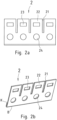
- two cheek parts 2, 2' are provided for the holding frame, namely a first cheek part 2 and a second cheek part 2'.
- the Fig. 2 a and Fig. 2 c show each of these cheek parts 2, 2' in a first perspective, in which the viewing direction is perpendicular to it.
- the Fig. 2 b and Fig. 2 d show the respective cheek part 2, 2' from an oblique view.
- Each cheek part 2, 2' which in the present embodiment is preferably a stamped and bent part, has three slots 21, 21', through which four equally sized tabs 22, 22' are formed.
- the number of tabs 22, 22' of the respective cheek part 2, 2' corresponds to the number of open recesses 123, 123' on each of the two side parts 12, 12' of the base frame 1.
- a locking window 23, 23' is provided in each tab 22, 22' of each cheek part 2, 2'.
- the locking windows 23 of the first cheek part 2 are larger than the locking windows 23' of the second cheek part 2'.
- the two cheek parts 2, 2' thus differ from one another in the size of their locking windows 23, 23'.
- additional fastening recesses 24, 24' are provided in the cheek parts 2, 2', which in the present embodiment have a circular shape, but could of course also have any other shape, for example oval, rectangular, square, triangular, pentagonal, n-sided or any other flat shape.
- the fastening pins 124, 124' of the base frame 1 fit positively into the respective fastening recesses 24, 24' of the corresponding Cheek parts 2, 2', so that the respective cheek part 2, 2' can be plugged onto the corresponding side part 12, 12'.
- the respective cheek part 2, 2' can be attached to the corresponding side part 12, 12' in another way, for example by gluing, welding, soldering, riveting and/or screwing.
- the Fig. 3 a and the Fig. 3 b show a module 3 that can be inserted into the support frame in a possible design from two different views. Of course, other modules with a similar design can also be used.
- the module 3 has a first locking lug 31 on a first longitudinal side 32, which is intended for locking in a locking window 23 of the first cheek part 2.
- a second longitudinal side 32' opposite this first longitudinal side 32 the module 3 has a second locking lug 31', which is narrower than the first locking lug and is intended for locking in a locking window 23' of the second cheek part 2'.
- the module is very compact, which improves its heat resistance.
- the orientation of the module 3 in the holding frame is determined by the shape of the locking lugs 31, 31' and the shape of the windows 23, 23'.
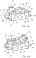
- the Fig. 4 shows a fully assembled holding frame, in which the two cheek parts 2, 2' are attached to the base frame.
- the fastening pins 124, 124' of the base frame engage in the fastening recesses 24, 24' of the corresponding cheek parts 2, 2'.
- this fastening is particularly stable because the lower edge K, K' of the respective sheet of the cheek part 2, 2' ends directly with the corresponding side part 12, 12' of the base frame 1.
- the cheek parts 2, 2' can also be soldered, welded, screwed, riveted or otherwise attached to the base frame 1.
- the cheek parts 2, 2' have a higher elasticity than the base frame 1, particularly in the area of their tabs 22, 22'.
- the base frame 1 therefore has a greater rigidity than the cheek parts 2, 2'.
- the cheek parts 2, 2' have a higher elasticity than the base frame.
- the holding frame is fixed at four corner points.
- it can be fixed by screwing at the four screw holes 131, 131 'of its flanges 13, 13' in or to a metal connector housing.
- this tab 22 is reversibly deflected, for example, by a distance of at least 0.2 mm, preferably of at least 0.4 mm, in particular of at least 0.8 mm, i.e., for example, by more than 1.6 mm.
- the base frame 1 is only deflected by a distance of less than 0.2 mm, preferably less than 0.1 mm, in particular less than 0.05 mm, i.e., for example, less than 0.025 mm, even in this area where its rigidity is at its lowest.
- the base frame 1 is stiffer than the cheek parts 2, 2'.
- the base frame 1 is to be regarded as stiff and the cheek parts 2, 2' are each to be described as spring-elastic.
- the cheek part 2 is spring-elastic and the elasticity of the cheek part 2 is selected in particular according to the values given above so that the modules 3 can be inserted and removed manually.
- the base frame 1 is rigid and in particular the rigidity of the base frame 1 is so high, in particular according to the values given above, that the inserted modules 3 are held therein with sufficient strength to ensure the intended function of an associated connector.
- the modules 3 and thus also the contacts present in the modules 3 are positioned geometrically precisely and mechanically stable enough to reliably make electrical contact with corresponding mating contacts of a comparable mating connector.
- Such a connector and a corresponding mating connector can additionally have a preferably metallic housing, into which a holding frame fully or partially equipped with modules 3 is inserted.
- FIG. 4 a and Fig. 4 b A specially designed PE module 3' is held in the holding frame shown, which in its basic form corresponds to the Fig. 3 a, b corresponds to the module 3 shown.
- the PE module 3' has an electrically conductive PE contact 33', which is electrically connected via the PE module 3' to an electrically conductive earthing clamp 34' that also belongs to the PE module 3'.
- the PE contact 33' can, for example, be a screw contact, ie the PE contact 33' has an earthing screw 35', which is suitable for conductively connecting an earthing cable to the PE contact 33' and mechanically fixing it thereto.
- This earthing cable is electrically connected to the base frame 1 by the PE module 3' via its earthing clamp 34', which is clamped to one of the end faces 11' of the holding frame.
- the holding frame can itself have such a PE contact, for example a PE screw contact, on its base frame 1.
- the PE contact can, for example, be molded onto the base frame 1. This can be done during the manufacture of the base frame 1, for example using an injection molding process.
- the holding frame serves to accommodate similar and/or different modules 3, wherein the holding frame is made of at least two different materials, of which at least one material is electrically conductive.
- the holding frame advantageously has partially spring-elastic properties.
- the holding frame consists partly of a rigid and partly of a spring-elastic material.
- the holding frame is made up of several parts.
- the holding frame consists of at least two parts, of which a first part is made of a first material and a second part is made of a second material, wherein the elastic modulus of the first material is greater than the elastic modulus of the second material.
- the first part can be designed as a base frame 1 and the second part as a cheek part 2, 2'.
- the base frame 1 has a rectangular cross-section and has two side parts 12, 12' that are parallel to one another and two end faces 11, 11' that are arranged perpendicularly thereto and parallel to one another.
- the base frame 1 is designed to be rigid.
- the base frame 1 can be made in one piece.
- the base frame 1 is at least partially made as a die-cast part.
- the at least one Cheek part 2, 2' is spring-elastic.
- the at least one cheek part 2, 2' can be electrically conductive and furthermore consists of spring-elastic sheet metal or has spring-elastic sheet metal.
- the at least one cheek part 2, 2' is attached to the base frame 1, for example by gluing, welding, soldering, riveting, locking and/or screwing.
- the at least one cheek part 2, 2' can have several slots 21, 21 through which tabs 22, 22' are formed in the respective cheek part 2, 2'.
- the width of the tabs 22, 22' can correspond to the width of the modules 3. In particular, all tabs 22, 22' can have the same width.
- Each tab 22, 22' can have a locking means.
- the locking means can consist of a locking window 23, 23' which is arranged in the respective tab 22, 22'.
- the at least one cheek part 2, 2' can in particular be a stamped and bent part.
- the at least one cheek part 2, 2' can be two cheek parts 2, 2'.
- the holding frame has a protective earthing contact (PE contact) or is at least equipped with one.
- the holding frame which is intended for a connector and is suitable for receiving similar and/or different modules 3, is made of at least two different materials.
- the base frame 1 is at least partially manufactured using a die-casting process, in particular using a zinc die-casting process.
- the at least one cheek part 2, 2' is punched out of a spring-elastic sheet metal and can be folded by 180° in particular at least one bending edge B, B'.
- the at least one cheek part 2, 2' can be attached to the base frame 1 in particular by gluing, welding, soldering, riveting, locking and/or screwing.
- the holding frame can hold a module 3 accommodated therein in one direction with its base frame and at the same time fix this module 3 perpendicularly thereto with tabs 13, 13', 23, 23' belonging to the respective cheek part 2, 2', in particular by locking the module 3 onto its tabs 22, 22'.
Landscapes
- Engineering & Computer Science (AREA)
- Manufacturing & Machinery (AREA)
- Connector Housings Or Holding Contact Members (AREA)
- Casings For Electric Apparatus (AREA)
- Manufacturing Of Electrical Connectors (AREA)
- Absorbent Articles And Supports Therefor (AREA)
Claims (6)
- Cadre de retenue pour un connecteur à fiches, à savoir un connecteur à fiches destiné à l'industrie lourde pour recevoir des modules similaires et/ou différents, avec une section principale pour bloquer un module dans un plan reçu et avec une section de déformation, qui peut prendre un état d'introduction et un état de retenue, dans lequel l'état d'introduction permet une introduction d'au moins un module dans une direction transversale par rapport au plan dans le cadre de retenue et un module reçu est bloqué dans l'état de retenue,dans lequel la section principale et la section de déformation sont formées au moins en partie à partir de matériaux différents,dans lequel la section principale (1) et la section de déformation (2, 2') présentent des propriétés de matériau différentes, à savoir des modules d'élasticité différents,dans lequel la section principale est un cadre principal périphérique, qui est réalisé de manière rectangulaire dans la section transversale et possède deux faces frontales se faisant face l'une l'autre parallèlement et, à angle droit par rapport à celles-ci, deux parties latérales se faisant face parallèlement, dans lequel les faces frontales sont plus courtes que les deux parties latérales, etdans lequel la section principale présente sur les faces frontales respectivement un flasque dépassant à angle droit par rapport à celles-ci, dans lequel chacun desdits flasques présente respectivement deux alésages pour vis si bien que le cadre principal possède au total quatre alésages pour vis, etdans lequel la section de déformation (2, 2') est réalisée en tant qu'au moins une partie de joue sur le cadre principal, etau moins une partie de la section de déformation (2, 2') est disposée à l'extérieur sur la section principale (1), et la section principale (1) et la section de déformation (2, 2') sont reliées entre elles par une liaison par la forme, par une liaison par la force et/ou par une liaison par la matière, etdans lequel la section de déformation (2, 2') est configurée pour une déformation élastique entre l'état d'introduction et l'état de retenue, etdans lequel la section de déformation (2, 2') présente une tôle élastique à la manière d'un ressort ou en est constituée, et les propriétés élastiques à la manière d'un ressort de la section de déformation (2, 2') permettent d'insérer, ou de retirer, individuellement des modules (3, 3'), etdans lequel la section de déformation est fabriquée au moins en partie avec une technique d'estampage-cintrage, etdans lequel le cadre de retenue présente un contact de mise à la terre de protection (33') ou en est équipé, etdans lequel la section principale (1) est fabriquée au moins en partie lors du moulage sous pression, à savoir à partir d'un métal, tel que du zinc, ou d'un alliage métallique, de préférence d'un alliage de zinc ou d'un alliage d'aluminium, etdans lequel la section principale présente une élasticité plus petite et ainsi une plus grande rigidité que la section de déformation, etdans lequel la section principale (1) est réalisée de manière rigide, et l'élasticité, plus élevée en comparaison avec la section principale, de la section de déformation (2, 2') est atteinte par- l'élasticité plus élevée du matériau utilisé pour la section de déformation (2, 2') par rapport au matériau de la section principale (1) et/ou- la forme géométrique de la section principale (1) et de la section de déformation (2, 2').
- Cadre de retenue selon la revendication 1, caractérisé en ce que le contact de mise à la terre de protection (33') est un contact pour vis, qui possède une vis de mise à la terre (35'), qui est adaptée pour relier un câble de mise à la terre de manière conductrice au contact de mise à la terre de protection (33') et pour l'y bloquer mécaniquement.
- Connecteur à fiches, à savoir un connecteur à fiches destine à l'industrie lourde, comprenant :un cadre de retenue selon l'une des revendications précédentes,des modules (3) similaires et/ou différents,un boîtier métallique de connecteur,dans lequel les modules (3) étant logés dans le cadre de retenue et le cadre de retenue étant monté avec les modules (3) dans le boîtier métallique du connecteur.
- Combinaison de deux connecteurs, chacun selon la revendication 3, en tant que connecteur et contre-connecteur.
- Procédé de fabrication d'un cadre de retenue pour un connecteur à fiches, à savoir un connecteur à fiches destiné à l'industrie lourde, pour recevoir des modules similaires et/ou différents, avec une section principale pour bloquer un module reçu dans un plan et une section de déformation, qui peut prendre un état d'introduction et un état de retenue, dans lequel l'état d'introduction permet une introduction d'au moins un module dans une direction de manière transversale par rapport au plan dans le cadre de retenue et un module reçu est bloqué dans l'état de retenue,charactérisé en ce que la section principale et la section de déformation sont formées au moins en partie à partir de matériaux différents,dans lequel la section principale et la section de déformation présentent des propriétés de matériau différentes, à savoir des modules d'élasticité différents,dans lequel la section principale forme un cadre principal périphérique et est réalisée de manière rectangulaire dans la section transversale et possède deux faces frontales se faisant face l'une l'autre parallèlement et, à angle droit par rapport à celles-ci, deux parties latérales se faisant face parallèlement, dans lequel les faces frontales sont plus courtes que les deux parties latérales, etla section principale présente sur les faces frontales respectivement un flasque dépassant de celles-ci à angle droit, dans lequel chacun desdits flasques présente respectivement deux alésages pour vis si bien que le cadre principal possède au total quatre alésages pour vis, etla section de déformation (2, 2') est réalisée en tant qu'au moins une partie de joue sur le cadre principal, etau moins une partie de la section de déformation (2, 2') est disposée à l'extérieur sur la section principale (1),et la section principale (1) et la section de déformation (2, 2') sont reliées entre elles par une liaison par la forme, par une liaison par la force et/ou par une liaison par la matière, etla section de déformation (2, 2') est configurée pour une déformation élastique entre l'état d'introduction et l'état de retenue, etla section de déformation (2, 2') présente une tôle élastique à la manière d'un ressort ou en est constituée, etles propriétés élastiques à la manière d'un ressort de la section de déformation (2, 2') permettent d'insérer ou de retirer individuellement des modules (3, 3'), etla section de déformation est fabriquée au moins en partie avec une technique d'estampage-cintrage, etle cadre de retenue présente un contact de mise à la terre de protection (33') ou en est équipé, etla section principale (1) est fabriquée au moins en partie lors du moulage sous pression, à savoir à partir d'un métal tel que du zinc ou d'un alliage métallique, de préférence d'un alliage de zinc ou d'un alliage d'aluminium,la section principale présente une élasticité plus petite et ainsi une plus grande rigidité que la section de déformation, etla section principale (1) est réalisée de manière rigide, et l'élasticité, plus élevée en comparaison avec la section principale, de la section de déformation (2, 2') est atteinte par- l'élasticité plus élevée du matériau utilisé pour la section de déformation (2, 2') par rapport au matériau de la section principale (1) et/ou- la forme géométrique de la section principale (1) et de la section de déformation (2, 2')de sorte que le cadre de retenue puisse appliquer de manière ciblée un couple de résistance plus élevé dans la zone de la contrainte de cintrage maximale.
- Procédé selon la revendication 5, caractérisé en ce que le contact de mise à la terre de protection est formé sur le cadre principal lors de la fabrication du cadre principal lors du procédé de moulage par injection.
Applications Claiming Priority (5)
| Application Number | Priority Date | Filing Date | Title |
|---|---|---|---|
| DE102013113976.0A DE102013113976B4 (de) | 2013-12-12 | 2013-12-12 | Halterahmen für einen Steckverbinder |
| DE102013113975.2A DE102013113975C5 (de) | 2013-12-12 | 2013-12-12 | Halterahmen für einen Steckverbinder |
| EP14830506.3A EP3080875B2 (fr) | 2013-12-12 | 2014-12-11 | Cadre de retenue pour un connecteur par enfichage |
| EP17163616.0A EP3217483B1 (fr) | 2013-12-12 | 2014-12-11 | Cadre de retenue pour connecteur à fiche |
| PCT/DE2014/100439 WO2015085995A1 (fr) | 2013-12-12 | 2014-12-11 | Cadre de retenue pour un connecteur par enfichage |
Related Parent Applications (3)
| Application Number | Title | Priority Date | Filing Date |
|---|---|---|---|
| EP17163616.0A Division EP3217483B1 (fr) | 2013-12-12 | 2014-12-11 | Cadre de retenue pour connecteur à fiche |
| EP14830506.3A Division EP3080875B2 (fr) | 2013-12-12 | 2014-12-11 | Cadre de retenue pour un connecteur par enfichage |
| EP14830506.3A Division-Into EP3080875B2 (fr) | 2013-12-12 | 2014-12-11 | Cadre de retenue pour un connecteur par enfichage |
Publications (3)
| Publication Number | Publication Date |
|---|---|
| EP4280397A2 EP4280397A2 (fr) | 2023-11-22 |
| EP4280397A3 EP4280397A3 (fr) | 2024-02-28 |
| EP4280397B1 true EP4280397B1 (fr) | 2025-01-29 |
Family
ID=52396325
Family Applications (3)
| Application Number | Title | Priority Date | Filing Date |
|---|---|---|---|
| EP23172202.6A Active EP4280397B1 (fr) | 2013-12-12 | 2014-12-11 | Cadre de retenue pour connecteur à fiche |
| EP17163616.0A Active EP3217483B1 (fr) | 2013-12-12 | 2014-12-11 | Cadre de retenue pour connecteur à fiche |
| EP14830506.3A Active EP3080875B2 (fr) | 2013-12-12 | 2014-12-11 | Cadre de retenue pour un connecteur par enfichage |
Family Applications After (2)
| Application Number | Title | Priority Date | Filing Date |
|---|---|---|---|
| EP17163616.0A Active EP3217483B1 (fr) | 2013-12-12 | 2014-12-11 | Cadre de retenue pour connecteur à fiche |
| EP14830506.3A Active EP3080875B2 (fr) | 2013-12-12 | 2014-12-11 | Cadre de retenue pour un connecteur par enfichage |
Country Status (12)
| Country | Link |
|---|---|
| US (3) | US10424892B2 (fr) |
| EP (3) | EP4280397B1 (fr) |
| JP (1) | JP6440714B2 (fr) |
| KR (1) | KR101798349B1 (fr) |
| CN (2) | CN108376869B (fr) |
| CA (1) | CA2930052C (fr) |
| DE (9) | DE202014011628U1 (fr) |
| DK (1) | DK3080875T3 (fr) |
| ES (1) | ES2630178T3 (fr) |
| PL (1) | PL3080875T3 (fr) |
| RU (1) | RU2650492C1 (fr) |
| WO (1) | WO2015085995A1 (fr) |
Families Citing this family (38)
| Publication number | Priority date | Publication date | Assignee | Title |
|---|---|---|---|---|
| WO2015085995A1 (fr) | 2013-12-12 | 2015-06-18 | Harting Electric Gmbh & Co. Kg | Cadre de retenue pour un connecteur par enfichage |
| PT2978075T (pt) * | 2014-07-22 | 2022-09-29 | Unger Kabel Konfektionstechnik Gmbh | Sistema de conexão de aparelhos com conexão de condutor de proteção integrada para aparelhos elétricos e aparelho elétrico |
| EP3067993B1 (fr) * | 2015-03-11 | 2019-01-30 | Phoenix Contact GmbH & Co. KG | Cadre de support destine a recevoir des inserts de contact modulaires |
| DE102016100794B4 (de) * | 2016-01-19 | 2019-03-28 | Harting Electric Gmbh & Co. Kg | Halterahmen mit Führungselement für Steckverbindermodule und System bestehend aus zwei dieser Halterahmen |
| DE102016203483B4 (de) * | 2016-03-03 | 2019-02-07 | Harting Electric Gmbh & Co. Kg | Modulsystem für modulare Steckverbinder |
| EP3400631B1 (fr) | 2016-06-23 | 2019-05-15 | Harting Electric GmbH & Co. KG | Châssis-support pour un connecteur et procédé de montage |
| CN205985533U (zh) * | 2016-07-12 | 2017-02-22 | 泰科电子(上海)有限公司 | 连接器 |
| DE102016213286A1 (de) | 2016-07-20 | 2018-01-25 | Harting Electric Gmbh & Co. Kg | Mehrteiliger Halterahmen, Konfektionier- und Bestückungsverfahren |
| DE102016213251A1 (de) | 2016-07-20 | 2018-01-25 | Harting Electric Gmbh & Co. Kg | Halterahmenanordnung mit Grundrahmen und Fixierelement und Bestückungsverfahren |
| DE102016116926A1 (de) | 2016-09-09 | 2018-03-15 | Harting Electric Gmbh & Co. Kg | Überspannungsschutzmodul für einen modularen Steckverbinder |
| USD856385S1 (en) * | 2016-10-19 | 2019-08-13 | Harting Electric Gmbh & Co. Kg | Hood connector |
| DE102016120304B4 (de) * | 2016-10-25 | 2020-10-08 | Lisa Dräxlmaier GmbH | Abgewinkelter steckverbinder und verfahren für dessen herstellung |
| DE102017106036B3 (de) * | 2017-03-21 | 2018-09-13 | Harting Electric Gmbh & Co. Kg | Halterahmen mit PE-Kontakt |
| DE102017003198B4 (de) * | 2017-04-03 | 2018-10-31 | Harting Electric Gmbh & Co. Kg | Steckverbindermodularsystem mit integriertem Datenbus |
| DE102017108430B4 (de) * | 2017-04-20 | 2021-09-30 | Harting Electric Gmbh & Co. Kg | Halterahmen für einen schweren Steckverbinder sowie System |
| DE102017108433B4 (de) * | 2017-04-20 | 2021-09-30 | Harting Electric Gmbh & Co. Kg | Halterahmen für einen Steckverbinder und Verfahren zur Bestückung |
| DE102017108432A1 (de) | 2017-04-20 | 2018-10-25 | Harting Electric Gmbh & Co. Kg | Halterahmen für einen Steckverbinder und Verfahren zur Bestückung |
| BE1025553B1 (de) * | 2017-08-16 | 2019-04-09 | Phoenix Contact Gmbh & Co. Kg | Baugruppe eines Steckverbinderteils mit einem Halterahmen und daran ansetzbare modulare Kontakteinsätze |
| BE1025564B1 (de) * | 2017-09-19 | 2019-04-19 | Phoenix Contact Gmbh & Co Kg | Modularer Anschlussblock mit einer Mehrzahl von Anschlussmodulen für ein Elektronikbauteil |
| DE102017124632A1 (de) * | 2017-10-23 | 2019-04-25 | Harting Electric Gmbh & Co. Kg | Halterahmen für einen Industriesteckverbinder |
| DE102018108968A1 (de) * | 2018-04-16 | 2019-10-17 | Harting Electric Gmbh & Co. Kg | Geschirmtes Steckverbindermodul für einen modularen Industriesteckverbinder |
| WO2019208220A1 (fr) * | 2018-04-26 | 2019-10-31 | 住友電装株式会社 | Connecteur |
| DE102018124322A1 (de) * | 2018-10-02 | 2020-04-02 | Phoenix Contact Gmbh & Co. Kg | Baugruppe einer elektrischen Einrichtung und Verfahren zum Herstellen einer solchen Baugruppe |
| JP6936203B2 (ja) * | 2018-10-23 | 2021-09-15 | 矢崎総業株式会社 | 端子台、三連端子台、及び車載機器 |
| USD938906S1 (en) * | 2018-12-26 | 2021-12-21 | Lg Chem, Ltd. | Front cover for battery module |
| JP7313185B2 (ja) * | 2019-04-30 | 2023-07-24 | タイコエレクトロニクスジャパン合同会社 | コネクタハウジング |
| DE102019112612B3 (de) * | 2019-05-14 | 2020-10-01 | Phoenix Contact Gmbh & Co. Kg | Halterahmen und Steckverbinder mit einem derartigen Halterahmen |
| EP4046242B1 (fr) * | 2019-10-16 | 2025-09-10 | HARTING Electric Stiftung & Co. KG | Cadre de maintien pour connecteur |
| WO2021075242A1 (fr) * | 2019-10-18 | 2021-04-22 | タイコエレクトロニクスジャパン合同会社 | Boîtier de connecteur |
| DE102019131804A1 (de) * | 2019-11-25 | 2021-05-27 | Phoenix Contact Gmbh & Co. Kg | Halterahmen, Steckverbinder sowie elektronisches Gerät |
| CN114731011B (zh) * | 2019-11-25 | 2024-12-17 | 菲尼克斯电气公司 | 保持框架、插式连接器以及电子设备 |
| DE102019131806A1 (de) * | 2019-11-25 | 2021-05-27 | Phoenix Contact Gmbh & Co. Kg | Halterahmen, Steckverbinder sowie elektronisches Gerät |
| DE102020101812A1 (de) * | 2020-01-27 | 2021-07-29 | Harting Electric Gmbh & Co. Kg | Anbaugehäuse |
| DE102020103845A1 (de) * | 2020-02-14 | 2021-08-19 | Phoenix Contact Gmbh & Co. Kg | Baugruppe eines Steckverbinderteils, Steckverbinderteil und elektronisches Gerät |
| TWI813989B (zh) * | 2021-05-05 | 2023-09-01 | 精英電腦股份有限公司 | 活動式鎖耳及包含其的電子裝置 |
| DE102023101556A1 (de) | 2023-01-23 | 2024-07-25 | Harting Electric Stiftung & Co. Kg | Hochstromsteckverbindersystem mit einstellbarer Trennkraft |
| CN120359669A (zh) | 2023-02-20 | 2025-07-22 | 浩亭电子基金会两合公司 | 连接器断开接合阻力机构 |
| WO2024182179A1 (fr) * | 2023-02-27 | 2024-09-06 | KYOCERA AVX Components Corporation | Connecteur à multiples composants |
Family Cites Families (52)
| Publication number | Priority date | Publication date | Assignee | Title |
|---|---|---|---|---|
| DE1816371U (de) | 1957-10-24 | 1960-08-11 | Busch Jaeger Duerener Metall | Rastvorrichtung elektrischer unterputzapparate. |
| US3544951A (en) | 1968-06-28 | 1970-12-01 | Deutsch Co Elec Comp | Coupling with deflectable arms |
| US3576520A (en) | 1969-04-11 | 1971-04-27 | Amp Inc | Mounting means for terminal junction modules |
| US4090764A (en) | 1973-12-19 | 1978-05-23 | The Deutsch Company Electronic Components Division | Modular electrical connector |
| US4032209A (en) † | 1976-01-15 | 1977-06-28 | Appleton Electric Company | Multiple socket assembly for electrical components |
| DE2736079C3 (de) | 1977-08-10 | 1980-03-06 | Air-Lb Gmbh, 6710 Frankenthal | Trägerschiene für einrastbare Reihenklemmen sowie Reihenklemme hierfür |
| FR2489609A1 (fr) | 1980-08-26 | 1982-03-05 | Lb Air | Module de raccordement de conducteurs electriques a connecteurs amovibles |
| FR2572857B1 (fr) | 1984-11-05 | 1986-12-26 | Sogie | Element de connecteur multicontacts et dispositif pour immobiliser un bloc isolant dans le boitier d'un tel element de connecteur |
| US4621885A (en) | 1985-09-20 | 1986-11-11 | Amp Incorporated | Ribbon cable connector with improved cover latch |
| US4735583A (en) | 1987-04-24 | 1988-04-05 | Amp Incorporated | Spring latch for latching together electrical connectors and improved latching system |
| US4952172A (en) | 1989-07-14 | 1990-08-28 | Amp Incorporated | Electrical connector stiffener device |
| FR2657469A1 (fr) | 1990-01-22 | 1991-07-26 | Aerospatiale | Barrette de raccordement electrique. |
| US5090920A (en) | 1990-04-17 | 1992-02-25 | Amp Incorporated | Module retention/ejection system |
| US5380216A (en) | 1992-05-11 | 1995-01-10 | The Whitaker Corporation | Cable backpanel interconnection |
| US5352133A (en) † | 1993-07-19 | 1994-10-04 | Molex Incorporated | Connector assembly having anti-overstress latch means |
| US5562493A (en) * | 1994-12-16 | 1996-10-08 | The Whitaker | Network interface assembly and mounting frame |
| DE29508095U1 (de) | 1995-05-17 | 1995-07-20 | HTS-Elektrotechnik GmbH, 53819 Neunkirchen-Seelscheid | Modulares Steckverbindersystem |
| EP0836246B1 (fr) | 1996-10-12 | 2002-07-17 | Molex Incorporated | Système de détrompage pour connecteur électrique |
| DE69620179T2 (de) | 1996-10-12 | 2002-11-07 | Molex Inc., Lisle | Elektrische Erdungshülle |
| DE19707120C1 (de) | 1997-02-22 | 1998-06-25 | Harting Kgaa | Halterahmen |
| JP3932151B2 (ja) | 1998-02-27 | 2007-06-20 | タイコエレクトロニクスアンプ株式会社 | 電気コネクタ組立体及びそれを用いた零挿入力接続組立体 |
| US6074238A (en) | 1998-05-15 | 2000-06-13 | Molex Incorporated | Electrical tap connector with spreader means |
| DE29812500U1 (de) | 1998-07-14 | 1998-09-10 | Industria Lombarda Materiale Elettrico I.L.M.E. S.P.A., Mailand/Milano | Modularer Steckverbinder |
| US6196869B1 (en) | 1998-10-30 | 2001-03-06 | Lucent Technologies Inc. | Mounting bracket and power bus for a connector block |
| US6371788B1 (en) | 2000-05-19 | 2002-04-16 | Molex Incorporated | Wafer connection latching assembly |
| US6556411B1 (en) | 2002-04-02 | 2003-04-29 | Marconi Communications, Inc. | Purge protection cartridge with three-way attachment clip |
| US7044802B2 (en) | 2003-09-11 | 2006-05-16 | Super Talent Electronics, Inc. | USB flash-memory card with perimeter frame and covers that allow mounting of chips on both sides of a PCB |
| US7488202B2 (en) | 2004-07-28 | 2009-02-10 | American Power Conversion Corporation | Multiport cabling system and method |
| CN100399637C (zh) | 2005-05-16 | 2008-07-02 | 富士康(昆山)电脑接插件有限公司 | 电连接器 |
| US7303446B2 (en) | 2005-05-18 | 2007-12-04 | 3M Innovative Proprties Company | Frame assembly |
| DE202005020026U1 (de) * | 2005-12-22 | 2006-03-16 | Harting Electric Gmbh & Co. Kg | Halterahmen für Steckermodule |
| JP4829060B2 (ja) | 2006-09-27 | 2011-11-30 | 矢崎総業株式会社 | 合体解除治具 |
| DE102008009357A1 (de) | 2008-02-14 | 2009-08-27 | Phoenix Contact Gmbh & Co. Kg | Elektrische Anschlusseinrichtung |
| US7597587B1 (en) | 2008-04-22 | 2009-10-06 | Tyco Electronics Corporation | Mountable connector assemblies and frames |
| JP5272636B2 (ja) | 2008-10-10 | 2013-08-28 | ミツミ電機株式会社 | モジュールコネクタ |
| US7811129B2 (en) * | 2008-12-05 | 2010-10-12 | Tyco Electronics Corporation | Electrical connector system |
| CN101807755B (zh) * | 2009-02-16 | 2012-06-20 | 富士康(昆山)电脑接插件有限公司 | 电连接器组件 |
| CN101932209A (zh) * | 2009-06-19 | 2010-12-29 | 鸿富锦精密工业(深圳)有限公司 | 壳体 |
| KR101355749B1 (ko) | 2009-12-09 | 2014-02-04 | 하르팅 에렉트릭 게엠베하 운트 코우. 카게 | 시스템 플러그 커넥터 |
| RU92746U1 (ru) * | 2009-12-18 | 2010-03-27 | Федеральное государственное унитарное предприятие "Производственное объединение "Уральский оптико-механический завод" имени Э.С. Яламова" | Соединитель для печатных плат |
| KR100988974B1 (ko) | 2010-03-12 | 2010-10-20 | 엘에스전선 주식회사 | 탄성 접촉편 및 이를 구비한 차폐 커넥터 |
| JP5388922B2 (ja) * | 2010-03-26 | 2014-01-15 | ホシデン株式会社 | コネクタ及び電子機器 |
| JP5559589B2 (ja) | 2010-04-21 | 2014-07-23 | 株式会社エスケイ工機 | ネットワーク装置の交換方法およびそれに用いる治具 |
| EP2581991B1 (fr) | 2011-10-13 | 2016-12-28 | Weidmüller Interface GmbH & Co. KG | Cadre de support pour connecteur à fiche |
| CN202333292U (zh) | 2011-10-14 | 2012-07-11 | 庆盟工业股份有限公司 | 连接接口模块结构 |
| CN202474421U (zh) * | 2012-02-17 | 2012-10-03 | 连展科技电子(昆山)有限公司 | 连接器结构 |
| RU125779U1 (ru) * | 2012-10-01 | 2013-03-10 | Открытое акционерное общество "Государственный Рязанский приборный завод" | Радиочастотный коаксиальный соединитель |
| CN203277786U (zh) † | 2013-01-29 | 2013-11-06 | 厦门唯恩电气有限公司 | 模块固定框架结构 |
| DE102013106279A1 (de) | 2013-06-17 | 2014-12-18 | Harting Electric Gmbh & Co. Kg | Halterahmen für Steckverbindermodule |
| DE202013103611U1 (de) | 2013-08-12 | 2013-09-19 | Harting Electric Gmbh & Co. Kg | Halterahmen für Steckverbinder |
| DE102013113976B4 (de) | 2013-12-12 | 2016-10-20 | Harting Electric Gmbh & Co. Kg | Halterahmen für einen Steckverbinder |
| WO2015085995A1 (fr) | 2013-12-12 | 2015-06-18 | Harting Electric Gmbh & Co. Kg | Cadre de retenue pour un connecteur par enfichage |
-
2014
- 2014-12-11 WO PCT/DE2014/100439 patent/WO2015085995A1/fr not_active Ceased
- 2014-12-11 DE DE202014011628.8U patent/DE202014011628U1/de not_active Expired - Lifetime
- 2014-12-11 EP EP23172202.6A patent/EP4280397B1/fr active Active
- 2014-12-11 KR KR1020167018665A patent/KR101798349B1/ko active Active
- 2014-12-11 DE DE202014011610.5U patent/DE202014011610U1/de not_active Expired - Lifetime
- 2014-12-11 CN CN201810455849.6A patent/CN108376869B/zh active Active
- 2014-12-11 DE DE202014011215.0U patent/DE202014011215U1/de not_active Expired - Lifetime
- 2014-12-11 CN CN201480067749.6A patent/CN105814748B/zh active Active
- 2014-12-11 DE DE202014011219.3U patent/DE202014011219U1/de not_active Expired - Lifetime
- 2014-12-11 JP JP2016538506A patent/JP6440714B2/ja active Active
- 2014-12-11 DE DE202014011216.9U patent/DE202014011216U1/de not_active Expired - Lifetime
- 2014-12-11 US US15/030,858 patent/US10424892B2/en active Active
- 2014-12-11 DE DE202014011449.8U patent/DE202014011449U1/de not_active Withdrawn - After Issue
- 2014-12-11 CA CA2930052A patent/CA2930052C/fr active Active
- 2014-12-11 DE DE202014011218.5U patent/DE202014011218U1/de not_active Expired - Lifetime
- 2014-12-11 EP EP17163616.0A patent/EP3217483B1/fr active Active
- 2014-12-11 PL PL14830506T patent/PL3080875T3/pl unknown
- 2014-12-11 EP EP14830506.3A patent/EP3080875B2/fr active Active
- 2014-12-11 DK DK14830506.3T patent/DK3080875T3/en active
- 2014-12-11 ES ES14830506.3T patent/ES2630178T3/es active Active
- 2014-12-11 DE DE202014011214.2U patent/DE202014011214U1/de not_active Expired - Lifetime
- 2014-12-11 DE DE202014011217.7U patent/DE202014011217U1/de not_active Expired - Lifetime
- 2014-12-11 RU RU2016125448A patent/RU2650492C1/ru active
-
2016
- 2016-09-20 US US15/271,128 patent/US10554007B2/en active Active
-
2018
- 2018-05-03 US US15/970,590 patent/US10418773B2/en active Active
Also Published As
Similar Documents
| Publication | Publication Date | Title |
|---|---|---|
| EP4280397B1 (fr) | Cadre de retenue pour connecteur à fiche | |
| DE102013113976B4 (de) | Halterahmen für einen Steckverbinder | |
| DE102013113975C5 (de) | Halterahmen für einen Steckverbinder | |
| EP3080874B2 (fr) | Cadre de retenue pour un connecteur par enfichage | |
| EP3480898B1 (fr) | Cadre de retenue modulaire pour connecteurs électriques | |
| EP3701595B1 (fr) | Cadre de retenue pour un connecteur industriel | |
| EP3488498B1 (fr) | Ensemble formant cadre de support muni d'un cadre de base et d'un élément de fixation et procédé d'assemblage | |
| EP3843221B1 (fr) | Cadre de support pour un connecteur | |
| EP2823536B1 (fr) | Fiche de raccordement avec pontet de conducteur de protection | |
| DE202015009386U1 (de) | System aus Steckverbinder-Modulrahmen und Adapterelementen sowie modularen Steckverbinder mit einem solchen System | |
| EP4033612A1 (fr) | Châssis-support en plusieurs parties procédé de montage et d'implantation | |
| DE102019104559A1 (de) | Halterahmen für eine Steckverbinder | |
| DE202018107326U1 (de) | Halterahmen für einen Steckverbinder | |
| DE102013022674B4 (de) | Halterahmen für einen Steckverbinder | |
| DE102013113973B4 (de) | Metallischer Halterahmen für einen Steckverbinder sowie Verfahren zur Herstellung | |
| DE102018133135A1 (de) | Halterahmen für einen Steckverbinder | |
| WO2024245492A1 (fr) | Appareil de fixation pour unités fonctionnelles d'un module de connecteur enfichable multifonctionnel, module de connecteur enfichable multifonctionnel et système modulaire de connecteur enfichable |
Legal Events
| Date | Code | Title | Description |
|---|---|---|---|
| PUAI | Public reference made under article 153(3) epc to a published international application that has entered the european phase |
Free format text: ORIGINAL CODE: 0009012 |
|
| STAA | Information on the status of an ep patent application or granted ep patent |
Free format text: STATUS: THE APPLICATION HAS BEEN PUBLISHED |
|
| AC | Divisional application: reference to earlier application |
Ref document number: 3080875 Country of ref document: EP Kind code of ref document: P Ref document number: 3217483 Country of ref document: EP Kind code of ref document: P |
|
| AK | Designated contracting states |
Kind code of ref document: A2 Designated state(s): AL AT BE BG CH CY CZ DE DK EE ES FI FR GB GR HR HU IE IS IT LI LT LU LV MC MK MT NL NO PL PT RO RS SE SI SK SM TR |
|
| REG | Reference to a national code |
Ref country code: DE Ref legal event code: R079 Free format text: PREVIOUS MAIN CLASS: H01R0043200000 Ref country code: DE Ref legal event code: R079 Ref document number: 502014016903 Country of ref document: DE Free format text: PREVIOUS MAIN CLASS: H01R0043200000 Ipc: H01R0013514000 |
|
| PUAL | Search report despatched |
Free format text: ORIGINAL CODE: 0009013 |
|
| AK | Designated contracting states |
Kind code of ref document: A3 Designated state(s): AL AT BE BG CH CY CZ DE DK EE ES FI FR GB GR HR HU IE IS IT LI LT LU LV MC MK MT NL NO PL PT RO RS SE SI SK SM TR |
|
| RIC1 | Information provided on ipc code assigned before grant |
Ipc: H01R 43/20 20060101ALI20240119BHEP Ipc: H01R 43/18 20060101ALI20240119BHEP Ipc: H01R 13/518 20060101ALI20240119BHEP Ipc: H01R 13/652 20060101ALI20240119BHEP Ipc: H01R 13/506 20060101ALI20240119BHEP Ipc: H01R 13/514 20060101AFI20240119BHEP |
|
| STAA | Information on the status of an ep patent application or granted ep patent |
Free format text: STATUS: REQUEST FOR EXAMINATION WAS MADE |
|
| 17P | Request for examination filed |
Effective date: 20240613 |
|
| RBV | Designated contracting states (corrected) |
Designated state(s): AL AT BE BG CH CY CZ DE DK EE ES FI FR GB GR HR HU IE IS IT LI LT LU LV MC MK MT NL NO PL PT RO RS SE SI SK SM TR |
|
| STAA | Information on the status of an ep patent application or granted ep patent |
Free format text: STATUS: EXAMINATION IS IN PROGRESS |
|
| 17Q | First examination report despatched |
Effective date: 20240730 |
|
| GRAP | Despatch of communication of intention to grant a patent |
Free format text: ORIGINAL CODE: EPIDOSNIGR1 |
|
| STAA | Information on the status of an ep patent application or granted ep patent |
Free format text: STATUS: GRANT OF PATENT IS INTENDED |
|
| GRAS | Grant fee paid |
Free format text: ORIGINAL CODE: EPIDOSNIGR3 |
|
| INTG | Intention to grant announced |
Effective date: 20241108 |
|
| GRAA | (expected) grant |
Free format text: ORIGINAL CODE: 0009210 |
|
| STAA | Information on the status of an ep patent application or granted ep patent |
Free format text: STATUS: THE PATENT HAS BEEN GRANTED |
|
| P01 | Opt-out of the competence of the unified patent court (upc) registered |
Free format text: CASE NUMBER: APP_64074/2024 Effective date: 20241203 |
|
| AC | Divisional application: reference to earlier application |
Ref document number: 3080875 Country of ref document: EP Kind code of ref document: P Ref document number: 3217483 Country of ref document: EP Kind code of ref document: P |
|
| AK | Designated contracting states |
Kind code of ref document: B1 Designated state(s): AL AT BE BG CH CY CZ DE DK EE ES FI FR GB GR HR HU IE IS IT LI LT LU LV MC MK MT NL NO PL PT RO RS SE SI SK SM TR |
|
| REG | Reference to a national code |
Ref country code: GB Ref legal event code: FG4D Free format text: NOT ENGLISH |
|
| REG | Reference to a national code |
Ref country code: CH Ref legal event code: EP |
|
| REG | Reference to a national code |
Ref country code: DE Ref legal event code: R096 Ref document number: 502014016903 Country of ref document: DE |
|
| REG | Reference to a national code |
Ref country code: IE Ref legal event code: FG4D Free format text: LANGUAGE OF EP DOCUMENT: GERMAN |
|
| REG | Reference to a national code |
Ref country code: NL Ref legal event code: MP Effective date: 20250129 |
|
| PG25 | Lapsed in a contracting state [announced via postgrant information from national office to epo] |
Ref country code: NL Free format text: LAPSE BECAUSE OF FAILURE TO SUBMIT A TRANSLATION OF THE DESCRIPTION OR TO PAY THE FEE WITHIN THE PRESCRIBED TIME-LIMIT Effective date: 20250129 |
|
| PG25 | Lapsed in a contracting state [announced via postgrant information from national office to epo] |
Ref country code: RS Free format text: LAPSE BECAUSE OF FAILURE TO SUBMIT A TRANSLATION OF THE DESCRIPTION OR TO PAY THE FEE WITHIN THE PRESCRIBED TIME-LIMIT Effective date: 20250429 |
|
| PG25 | Lapsed in a contracting state [announced via postgrant information from national office to epo] |
Ref country code: FI Free format text: LAPSE BECAUSE OF FAILURE TO SUBMIT A TRANSLATION OF THE DESCRIPTION OR TO PAY THE FEE WITHIN THE PRESCRIBED TIME-LIMIT Effective date: 20250129 |
|
| PG25 | Lapsed in a contracting state [announced via postgrant information from national office to epo] |
Ref country code: PL Free format text: LAPSE BECAUSE OF FAILURE TO SUBMIT A TRANSLATION OF THE DESCRIPTION OR TO PAY THE FEE WITHIN THE PRESCRIBED TIME-LIMIT Effective date: 20250129 |
|
| PG25 | Lapsed in a contracting state [announced via postgrant information from national office to epo] |
Ref country code: ES Free format text: LAPSE BECAUSE OF FAILURE TO SUBMIT A TRANSLATION OF THE DESCRIPTION OR TO PAY THE FEE WITHIN THE PRESCRIBED TIME-LIMIT Effective date: 20250129 |
|
| REG | Reference to a national code |
Ref country code: LT Ref legal event code: MG9D |
|
| PG25 | Lapsed in a contracting state [announced via postgrant information from national office to epo] |
Ref country code: IS Free format text: LAPSE BECAUSE OF FAILURE TO SUBMIT A TRANSLATION OF THE DESCRIPTION OR TO PAY THE FEE WITHIN THE PRESCRIBED TIME-LIMIT Effective date: 20250529 Ref country code: NO Free format text: LAPSE BECAUSE OF FAILURE TO SUBMIT A TRANSLATION OF THE DESCRIPTION OR TO PAY THE FEE WITHIN THE PRESCRIBED TIME-LIMIT Effective date: 20250429 |
|
| PG25 | Lapsed in a contracting state [announced via postgrant information from national office to epo] |
Ref country code: HR Free format text: LAPSE BECAUSE OF FAILURE TO SUBMIT A TRANSLATION OF THE DESCRIPTION OR TO PAY THE FEE WITHIN THE PRESCRIBED TIME-LIMIT Effective date: 20250129 |
|
| PG25 | Lapsed in a contracting state [announced via postgrant information from national office to epo] |
Ref country code: PT Free format text: LAPSE BECAUSE OF FAILURE TO SUBMIT A TRANSLATION OF THE DESCRIPTION OR TO PAY THE FEE WITHIN THE PRESCRIBED TIME-LIMIT Effective date: 20250529 Ref country code: LV Free format text: LAPSE BECAUSE OF FAILURE TO SUBMIT A TRANSLATION OF THE DESCRIPTION OR TO PAY THE FEE WITHIN THE PRESCRIBED TIME-LIMIT Effective date: 20250129 |
|
| PG25 | Lapsed in a contracting state [announced via postgrant information from national office to epo] |
Ref country code: BG Free format text: LAPSE BECAUSE OF FAILURE TO SUBMIT A TRANSLATION OF THE DESCRIPTION OR TO PAY THE FEE WITHIN THE PRESCRIBED TIME-LIMIT Effective date: 20250129 Ref country code: GR Free format text: LAPSE BECAUSE OF FAILURE TO SUBMIT A TRANSLATION OF THE DESCRIPTION OR TO PAY THE FEE WITHIN THE PRESCRIBED TIME-LIMIT Effective date: 20250430 |
|
| PG25 | Lapsed in a contracting state [announced via postgrant information from national office to epo] |
Ref country code: SE Free format text: LAPSE BECAUSE OF FAILURE TO SUBMIT A TRANSLATION OF THE DESCRIPTION OR TO PAY THE FEE WITHIN THE PRESCRIBED TIME-LIMIT Effective date: 20250129 |
|
| REG | Reference to a national code |
Ref country code: DE Ref legal event code: R081 Ref document number: 502014016903 Country of ref document: DE Owner name: HARTING ELECTRIC GMBH & CO. KG, DE Free format text: FORMER OWNER: ANMELDERANGABEN UNKLAR / UNVOLLSTAENDIG, 80297 MUENCHEN, DE |
|
| PG25 | Lapsed in a contracting state [announced via postgrant information from national office to epo] |
Ref country code: SM Free format text: LAPSE BECAUSE OF FAILURE TO SUBMIT A TRANSLATION OF THE DESCRIPTION OR TO PAY THE FEE WITHIN THE PRESCRIBED TIME-LIMIT Effective date: 20250129 |
|
| PG25 | Lapsed in a contracting state [announced via postgrant information from national office to epo] |
Ref country code: DK Free format text: LAPSE BECAUSE OF FAILURE TO SUBMIT A TRANSLATION OF THE DESCRIPTION OR TO PAY THE FEE WITHIN THE PRESCRIBED TIME-LIMIT Effective date: 20250129 |
|
| PG25 | Lapsed in a contracting state [announced via postgrant information from national office to epo] |
Ref country code: IT Free format text: LAPSE BECAUSE OF FAILURE TO SUBMIT A TRANSLATION OF THE DESCRIPTION OR TO PAY THE FEE WITHIN THE PRESCRIBED TIME-LIMIT Effective date: 20250129 |
|
| PG25 | Lapsed in a contracting state [announced via postgrant information from national office to epo] |
Ref country code: EE Free format text: LAPSE BECAUSE OF FAILURE TO SUBMIT A TRANSLATION OF THE DESCRIPTION OR TO PAY THE FEE WITHIN THE PRESCRIBED TIME-LIMIT Effective date: 20250129 Ref country code: CZ Free format text: LAPSE BECAUSE OF FAILURE TO SUBMIT A TRANSLATION OF THE DESCRIPTION OR TO PAY THE FEE WITHIN THE PRESCRIBED TIME-LIMIT Effective date: 20250129 |
|
| PG25 | Lapsed in a contracting state [announced via postgrant information from national office to epo] |
Ref country code: RO Free format text: LAPSE BECAUSE OF FAILURE TO SUBMIT A TRANSLATION OF THE DESCRIPTION OR TO PAY THE FEE WITHIN THE PRESCRIBED TIME-LIMIT Effective date: 20250129 |
|
| PG25 | Lapsed in a contracting state [announced via postgrant information from national office to epo] |
Ref country code: SK Free format text: LAPSE BECAUSE OF FAILURE TO SUBMIT A TRANSLATION OF THE DESCRIPTION OR TO PAY THE FEE WITHIN THE PRESCRIBED TIME-LIMIT Effective date: 20250129 |
|
| REG | Reference to a national code |
Ref country code: DE Ref legal event code: R097 Ref document number: 502014016903 Country of ref document: DE |
|
| PLBE | No opposition filed within time limit |
Free format text: ORIGINAL CODE: 0009261 |
|
| STAA | Information on the status of an ep patent application or granted ep patent |
Free format text: STATUS: NO OPPOSITION FILED WITHIN TIME LIMIT |
|
| 26N | No opposition filed |
Effective date: 20251030 |
|
| PGFP | Annual fee paid to national office [announced via postgrant information from national office to epo] |
Ref country code: GB Payment date: 20251223 Year of fee payment: 12 |
|
| PGFP | Annual fee paid to national office [announced via postgrant information from national office to epo] |
Ref country code: FR Payment date: 20251223 Year of fee payment: 12 |
|
| PGFP | Annual fee paid to national office [announced via postgrant information from national office to epo] |
Ref country code: DE Payment date: 20251229 Year of fee payment: 12 |