EP4253179B1 - Method for controlling electric vehicle and system for controlling electric vehicle - Google Patents
Method for controlling electric vehicle and system for controlling electric vehicle Download PDFInfo
- Publication number
- EP4253179B1 EP4253179B1 EP20959790.5A EP20959790A EP4253179B1 EP 4253179 B1 EP4253179 B1 EP 4253179B1 EP 20959790 A EP20959790 A EP 20959790A EP 4253179 B1 EP4253179 B1 EP 4253179B1
- Authority
- EP
- European Patent Office
- Prior art keywords
- torque
- braking torque
- wheel
- slip
- motor
- Prior art date
- Legal status (The legal status is an assumption and is not a legal conclusion. Google has not performed a legal analysis and makes no representation as to the accuracy of the status listed.)
- Active
Links
Images




Classifications
-
- B—PERFORMING OPERATIONS; TRANSPORTING
- B60—VEHICLES IN GENERAL
- B60K—ARRANGEMENT OR MOUNTING OF PROPULSION UNITS OR OF TRANSMISSIONS IN VEHICLES; ARRANGEMENT OR MOUNTING OF PLURAL DIVERSE PRIME-MOVERS IN VEHICLES; AUXILIARY DRIVES FOR VEHICLES; INSTRUMENTATION OR DASHBOARDS FOR VEHICLES; ARRANGEMENTS IN CONNECTION WITH COOLING, AIR INTAKE, GAS EXHAUST OR FUEL SUPPLY OF PROPULSION UNITS IN VEHICLES
- B60K6/00—Arrangement or mounting of plural diverse prime-movers for mutual or common propulsion, e.g. hybrid propulsion systems comprising electric motors and internal combustion engines
- B60K6/20—Arrangement or mounting of plural diverse prime-movers for mutual or common propulsion, e.g. hybrid propulsion systems comprising electric motors and internal combustion engines the prime-movers consisting of electric motors and internal combustion engines, e.g. HEVs
- B60K6/50—Architecture of the driveline characterised by arrangement or kind of transmission units
- B60K6/52—Driving a plurality of drive axles, e.g. four-wheel drive
-
- B—PERFORMING OPERATIONS; TRANSPORTING
- B60—VEHICLES IN GENERAL
- B60K—ARRANGEMENT OR MOUNTING OF PROPULSION UNITS OR OF TRANSMISSIONS IN VEHICLES; ARRANGEMENT OR MOUNTING OF PLURAL DIVERSE PRIME-MOVERS IN VEHICLES; AUXILIARY DRIVES FOR VEHICLES; INSTRUMENTATION OR DASHBOARDS FOR VEHICLES; ARRANGEMENTS IN CONNECTION WITH COOLING, AIR INTAKE, GAS EXHAUST OR FUEL SUPPLY OF PROPULSION UNITS IN VEHICLES
- B60K1/00—Arrangement or mounting of electrical propulsion units
- B60K1/02—Arrangement or mounting of electrical propulsion units comprising more than one electric motor
-
- B—PERFORMING OPERATIONS; TRANSPORTING
- B60—VEHICLES IN GENERAL
- B60K—ARRANGEMENT OR MOUNTING OF PROPULSION UNITS OR OF TRANSMISSIONS IN VEHICLES; ARRANGEMENT OR MOUNTING OF PLURAL DIVERSE PRIME-MOVERS IN VEHICLES; AUXILIARY DRIVES FOR VEHICLES; INSTRUMENTATION OR DASHBOARDS FOR VEHICLES; ARRANGEMENTS IN CONNECTION WITH COOLING, AIR INTAKE, GAS EXHAUST OR FUEL SUPPLY OF PROPULSION UNITS IN VEHICLES
- B60K17/00—Arrangement or mounting of transmissions in vehicles
- B60K17/34—Arrangement or mounting of transmissions in vehicles for driving both front and rear wheels, e.g. four wheel drive vehicles
- B60K17/356—Arrangement or mounting of transmissions in vehicles for driving both front and rear wheels, e.g. four wheel drive vehicles having fluid or electric motor, for driving one or more wheels
-
- B—PERFORMING OPERATIONS; TRANSPORTING
- B60—VEHICLES IN GENERAL
- B60K—ARRANGEMENT OR MOUNTING OF PROPULSION UNITS OR OF TRANSMISSIONS IN VEHICLES; ARRANGEMENT OR MOUNTING OF PLURAL DIVERSE PRIME-MOVERS IN VEHICLES; AUXILIARY DRIVES FOR VEHICLES; INSTRUMENTATION OR DASHBOARDS FOR VEHICLES; ARRANGEMENTS IN CONNECTION WITH COOLING, AIR INTAKE, GAS EXHAUST OR FUEL SUPPLY OF PROPULSION UNITS IN VEHICLES
- B60K23/00—Arrangement or mounting of control devices for vehicle transmissions, or parts thereof, not otherwise provided for
- B60K23/08—Arrangement or mounting of control devices for vehicle transmissions, or parts thereof, not otherwise provided for for changing number of driven wheels, for switching from driving one axle to driving two or more axles
- B60K23/0808—Arrangement or mounting of control devices for vehicle transmissions, or parts thereof, not otherwise provided for for changing number of driven wheels, for switching from driving one axle to driving two or more axles for varying torque distribution between driven axles, e.g. by transfer clutch
-
- B—PERFORMING OPERATIONS; TRANSPORTING
- B60—VEHICLES IN GENERAL
- B60L—PROPULSION OF ELECTRICALLY-PROPELLED VEHICLES; SUPPLYING ELECTRIC POWER FOR AUXILIARY EQUIPMENT OF ELECTRICALLY-PROPELLED VEHICLES; ELECTRODYNAMIC BRAKE SYSTEMS FOR VEHICLES IN GENERAL; MAGNETIC SUSPENSION OR LEVITATION FOR VEHICLES; MONITORING OPERATING VARIABLES OF ELECTRICALLY-PROPELLED VEHICLES; ELECTRIC SAFETY DEVICES FOR ELECTRICALLY-PROPELLED VEHICLES
- B60L15/00—Methods, circuits, or devices for controlling the traction-motor speed of electrically-propelled vehicles
- B60L15/20—Methods, circuits, or devices for controlling the traction-motor speed of electrically-propelled vehicles for control of the vehicle or its driving motor to achieve a desired performance, e.g. speed, torque, programmed variation of speed
- B60L15/2009—Methods, circuits, or devices for controlling the traction-motor speed of electrically-propelled vehicles for control of the vehicle or its driving motor to achieve a desired performance, e.g. speed, torque, programmed variation of speed for braking
-
- B—PERFORMING OPERATIONS; TRANSPORTING
- B60—VEHICLES IN GENERAL
- B60L—PROPULSION OF ELECTRICALLY-PROPELLED VEHICLES; SUPPLYING ELECTRIC POWER FOR AUXILIARY EQUIPMENT OF ELECTRICALLY-PROPELLED VEHICLES; ELECTRODYNAMIC BRAKE SYSTEMS FOR VEHICLES IN GENERAL; MAGNETIC SUSPENSION OR LEVITATION FOR VEHICLES; MONITORING OPERATING VARIABLES OF ELECTRICALLY-PROPELLED VEHICLES; ELECTRIC SAFETY DEVICES FOR ELECTRICALLY-PROPELLED VEHICLES
- B60L15/00—Methods, circuits, or devices for controlling the traction-motor speed of electrically-propelled vehicles
- B60L15/32—Control or regulation of multiple-unit electrically-propelled vehicles
-
- B—PERFORMING OPERATIONS; TRANSPORTING
- B60—VEHICLES IN GENERAL
- B60L—PROPULSION OF ELECTRICALLY-PROPELLED VEHICLES; SUPPLYING ELECTRIC POWER FOR AUXILIARY EQUIPMENT OF ELECTRICALLY-PROPELLED VEHICLES; ELECTRODYNAMIC BRAKE SYSTEMS FOR VEHICLES IN GENERAL; MAGNETIC SUSPENSION OR LEVITATION FOR VEHICLES; MONITORING OPERATING VARIABLES OF ELECTRICALLY-PROPELLED VEHICLES; ELECTRIC SAFETY DEVICES FOR ELECTRICALLY-PROPELLED VEHICLES
- B60L3/00—Electric devices on electrically-propelled vehicles for safety purposes; Monitoring operating variables, e.g. speed, deceleration or energy consumption
- B60L3/10—Indicating wheel slip ; Correction of wheel slip
-
- B—PERFORMING OPERATIONS; TRANSPORTING
- B60—VEHICLES IN GENERAL
- B60L—PROPULSION OF ELECTRICALLY-PROPELLED VEHICLES; SUPPLYING ELECTRIC POWER FOR AUXILIARY EQUIPMENT OF ELECTRICALLY-PROPELLED VEHICLES; ELECTRODYNAMIC BRAKE SYSTEMS FOR VEHICLES IN GENERAL; MAGNETIC SUSPENSION OR LEVITATION FOR VEHICLES; MONITORING OPERATING VARIABLES OF ELECTRICALLY-PROPELLED VEHICLES; ELECTRIC SAFETY DEVICES FOR ELECTRICALLY-PROPELLED VEHICLES
- B60L7/00—Electrodynamic brake systems for vehicles in general
- B60L7/24—Electrodynamic brake systems for vehicles in general with additional mechanical or electromagnetic braking
- B60L7/26—Controlling the braking effect
-
- B—PERFORMING OPERATIONS; TRANSPORTING
- B60—VEHICLES IN GENERAL
- B60T—VEHICLE BRAKE CONTROL SYSTEMS OR PARTS THEREOF; BRAKE CONTROL SYSTEMS OR PARTS THEREOF, IN GENERAL; ARRANGEMENT OF BRAKING ELEMENTS ON VEHICLES IN GENERAL; PORTABLE DEVICES FOR PREVENTING UNWANTED MOVEMENT OF VEHICLES; VEHICLE MODIFICATIONS TO FACILITATE COOLING OF BRAKES
- B60T1/00—Arrangements of braking elements, i.e. of those parts where braking effect occurs specially for vehicles
- B60T1/02—Arrangements of braking elements, i.e. of those parts where braking effect occurs specially for vehicles acting by retarding wheels
- B60T1/10—Arrangements of braking elements, i.e. of those parts where braking effect occurs specially for vehicles acting by retarding wheels by utilising wheel movement for accumulating energy, e.g. driving air compressors
-
- B—PERFORMING OPERATIONS; TRANSPORTING
- B60—VEHICLES IN GENERAL
- B60T—VEHICLE BRAKE CONTROL SYSTEMS OR PARTS THEREOF; BRAKE CONTROL SYSTEMS OR PARTS THEREOF, IN GENERAL; ARRANGEMENT OF BRAKING ELEMENTS ON VEHICLES IN GENERAL; PORTABLE DEVICES FOR PREVENTING UNWANTED MOVEMENT OF VEHICLES; VEHICLE MODIFICATIONS TO FACILITATE COOLING OF BRAKES
- B60T8/00—Arrangements for adjusting wheel-braking force to meet varying vehicular or ground-surface conditions, e.g. limiting or varying distribution of braking force
- B60T8/17—Using electrical or electronic regulation means to control braking
- B60T8/1701—Braking or traction control means specially adapted for particular types of vehicles
-
- B—PERFORMING OPERATIONS; TRANSPORTING
- B60—VEHICLES IN GENERAL
- B60W—CONJOINT CONTROL OF VEHICLE SUB-UNITS OF DIFFERENT TYPE OR DIFFERENT FUNCTION; CONTROL SYSTEMS SPECIALLY ADAPTED FOR HYBRID VEHICLES; ROAD VEHICLE DRIVE CONTROL SYSTEMS FOR PURPOSES NOT RELATED TO THE CONTROL OF A PARTICULAR SUB-UNIT
- B60W10/00—Conjoint control of vehicle sub-units of different type or different function
- B60W10/04—Conjoint control of vehicle sub-units of different type or different function including control of propulsion units
- B60W10/08—Conjoint control of vehicle sub-units of different type or different function including control of propulsion units including control of electric propulsion units, e.g. motors or generators
-
- B—PERFORMING OPERATIONS; TRANSPORTING
- B60—VEHICLES IN GENERAL
- B60W—CONJOINT CONTROL OF VEHICLE SUB-UNITS OF DIFFERENT TYPE OR DIFFERENT FUNCTION; CONTROL SYSTEMS SPECIALLY ADAPTED FOR HYBRID VEHICLES; ROAD VEHICLE DRIVE CONTROL SYSTEMS FOR PURPOSES NOT RELATED TO THE CONTROL OF A PARTICULAR SUB-UNIT
- B60W20/00—Control systems specially adapted for hybrid vehicles
- B60W20/10—Controlling the power contribution of each of the prime movers to meet required power demand
- B60W20/13—Controlling the power contribution of each of the prime movers to meet required power demand in order to stay within battery power input or output limits; in order to prevent overcharging or battery depletion
- B60W20/14—Controlling the power contribution of each of the prime movers to meet required power demand in order to stay within battery power input or output limits; in order to prevent overcharging or battery depletion in conjunction with braking regeneration
-
- B—PERFORMING OPERATIONS; TRANSPORTING
- B60—VEHICLES IN GENERAL
- B60W—CONJOINT CONTROL OF VEHICLE SUB-UNITS OF DIFFERENT TYPE OR DIFFERENT FUNCTION; CONTROL SYSTEMS SPECIALLY ADAPTED FOR HYBRID VEHICLES; ROAD VEHICLE DRIVE CONTROL SYSTEMS FOR PURPOSES NOT RELATED TO THE CONTROL OF A PARTICULAR SUB-UNIT
- B60W30/00—Purposes of road vehicle drive control systems not related to the control of a particular sub-unit, e.g. of systems using conjoint control of vehicle sub-units
- B60W30/02—Control of vehicle driving stability
-
- B—PERFORMING OPERATIONS; TRANSPORTING
- B60—VEHICLES IN GENERAL
- B60W—CONJOINT CONTROL OF VEHICLE SUB-UNITS OF DIFFERENT TYPE OR DIFFERENT FUNCTION; CONTROL SYSTEMS SPECIALLY ADAPTED FOR HYBRID VEHICLES; ROAD VEHICLE DRIVE CONTROL SYSTEMS FOR PURPOSES NOT RELATED TO THE CONTROL OF A PARTICULAR SUB-UNIT
- B60W30/00—Purposes of road vehicle drive control systems not related to the control of a particular sub-unit, e.g. of systems using conjoint control of vehicle sub-units
- B60W30/18—Propelling the vehicle
- B60W30/18009—Propelling the vehicle related to particular drive situations
- B60W30/18109—Braking
- B60W30/18127—Regenerative braking
-
- B—PERFORMING OPERATIONS; TRANSPORTING
- B60—VEHICLES IN GENERAL
- B60W—CONJOINT CONTROL OF VEHICLE SUB-UNITS OF DIFFERENT TYPE OR DIFFERENT FUNCTION; CONTROL SYSTEMS SPECIALLY ADAPTED FOR HYBRID VEHICLES; ROAD VEHICLE DRIVE CONTROL SYSTEMS FOR PURPOSES NOT RELATED TO THE CONTROL OF A PARTICULAR SUB-UNIT
- B60W30/00—Purposes of road vehicle drive control systems not related to the control of a particular sub-unit, e.g. of systems using conjoint control of vehicle sub-units
- B60W30/18—Propelling the vehicle
- B60W30/18172—Preventing, or responsive to skidding of wheels
-
- B—PERFORMING OPERATIONS; TRANSPORTING
- B60—VEHICLES IN GENERAL
- B60L—PROPULSION OF ELECTRICALLY-PROPELLED VEHICLES; SUPPLYING ELECTRIC POWER FOR AUXILIARY EQUIPMENT OF ELECTRICALLY-PROPELLED VEHICLES; ELECTRODYNAMIC BRAKE SYSTEMS FOR VEHICLES IN GENERAL; MAGNETIC SUSPENSION OR LEVITATION FOR VEHICLES; MONITORING OPERATING VARIABLES OF ELECTRICALLY-PROPELLED VEHICLES; ELECTRIC SAFETY DEVICES FOR ELECTRICALLY-PROPELLED VEHICLES
- B60L2220/00—Electrical machine types; Structures or applications thereof
- B60L2220/40—Electrical machine applications
- B60L2220/42—Electrical machine applications with use of more than one motor
-
- B—PERFORMING OPERATIONS; TRANSPORTING
- B60—VEHICLES IN GENERAL
- B60L—PROPULSION OF ELECTRICALLY-PROPELLED VEHICLES; SUPPLYING ELECTRIC POWER FOR AUXILIARY EQUIPMENT OF ELECTRICALLY-PROPELLED VEHICLES; ELECTRODYNAMIC BRAKE SYSTEMS FOR VEHICLES IN GENERAL; MAGNETIC SUSPENSION OR LEVITATION FOR VEHICLES; MONITORING OPERATING VARIABLES OF ELECTRICALLY-PROPELLED VEHICLES; ELECTRIC SAFETY DEVICES FOR ELECTRICALLY-PROPELLED VEHICLES
- B60L2240/00—Control parameters of input or output; Target parameters
- B60L2240/10—Vehicle control parameters
- B60L2240/12—Speed
-
- B—PERFORMING OPERATIONS; TRANSPORTING
- B60—VEHICLES IN GENERAL
- B60L—PROPULSION OF ELECTRICALLY-PROPELLED VEHICLES; SUPPLYING ELECTRIC POWER FOR AUXILIARY EQUIPMENT OF ELECTRICALLY-PROPELLED VEHICLES; ELECTRODYNAMIC BRAKE SYSTEMS FOR VEHICLES IN GENERAL; MAGNETIC SUSPENSION OR LEVITATION FOR VEHICLES; MONITORING OPERATING VARIABLES OF ELECTRICALLY-PROPELLED VEHICLES; ELECTRIC SAFETY DEVICES FOR ELECTRICALLY-PROPELLED VEHICLES
- B60L2240/00—Control parameters of input or output; Target parameters
- B60L2240/40—Drive Train control parameters
- B60L2240/42—Drive Train control parameters related to electric machines
- B60L2240/421—Speed
-
- B—PERFORMING OPERATIONS; TRANSPORTING
- B60—VEHICLES IN GENERAL
- B60L—PROPULSION OF ELECTRICALLY-PROPELLED VEHICLES; SUPPLYING ELECTRIC POWER FOR AUXILIARY EQUIPMENT OF ELECTRICALLY-PROPELLED VEHICLES; ELECTRODYNAMIC BRAKE SYSTEMS FOR VEHICLES IN GENERAL; MAGNETIC SUSPENSION OR LEVITATION FOR VEHICLES; MONITORING OPERATING VARIABLES OF ELECTRICALLY-PROPELLED VEHICLES; ELECTRIC SAFETY DEVICES FOR ELECTRICALLY-PROPELLED VEHICLES
- B60L2240/00—Control parameters of input or output; Target parameters
- B60L2240/40—Drive Train control parameters
- B60L2240/42—Drive Train control parameters related to electric machines
- B60L2240/423—Torque
-
- B—PERFORMING OPERATIONS; TRANSPORTING
- B60—VEHICLES IN GENERAL
- B60L—PROPULSION OF ELECTRICALLY-PROPELLED VEHICLES; SUPPLYING ELECTRIC POWER FOR AUXILIARY EQUIPMENT OF ELECTRICALLY-PROPELLED VEHICLES; ELECTRODYNAMIC BRAKE SYSTEMS FOR VEHICLES IN GENERAL; MAGNETIC SUSPENSION OR LEVITATION FOR VEHICLES; MONITORING OPERATING VARIABLES OF ELECTRICALLY-PROPELLED VEHICLES; ELECTRIC SAFETY DEVICES FOR ELECTRICALLY-PROPELLED VEHICLES
- B60L2240/00—Control parameters of input or output; Target parameters
- B60L2240/40—Drive Train control parameters
- B60L2240/48—Drive Train control parameters related to transmissions
-
- B—PERFORMING OPERATIONS; TRANSPORTING
- B60—VEHICLES IN GENERAL
- B60L—PROPULSION OF ELECTRICALLY-PROPELLED VEHICLES; SUPPLYING ELECTRIC POWER FOR AUXILIARY EQUIPMENT OF ELECTRICALLY-PROPELLED VEHICLES; ELECTRODYNAMIC BRAKE SYSTEMS FOR VEHICLES IN GENERAL; MAGNETIC SUSPENSION OR LEVITATION FOR VEHICLES; MONITORING OPERATING VARIABLES OF ELECTRICALLY-PROPELLED VEHICLES; ELECTRIC SAFETY DEVICES FOR ELECTRICALLY-PROPELLED VEHICLES
- B60L2250/00—Driver interactions
- B60L2250/26—Driver interactions by pedal actuation
- B60L2250/28—Accelerator pedal thresholds
-
- B—PERFORMING OPERATIONS; TRANSPORTING
- B60—VEHICLES IN GENERAL
- B60T—VEHICLE BRAKE CONTROL SYSTEMS OR PARTS THEREOF; BRAKE CONTROL SYSTEMS OR PARTS THEREOF, IN GENERAL; ARRANGEMENT OF BRAKING ELEMENTS ON VEHICLES IN GENERAL; PORTABLE DEVICES FOR PREVENTING UNWANTED MOVEMENT OF VEHICLES; VEHICLE MODIFICATIONS TO FACILITATE COOLING OF BRAKES
- B60T2270/00—Further aspects of brake control systems not otherwise provided for
- B60T2270/60—Regenerative braking
- B60T2270/608—Electronic brake distribution (EBV/EBD) features related thereto
-
- B—PERFORMING OPERATIONS; TRANSPORTING
- B60—VEHICLES IN GENERAL
- B60W—CONJOINT CONTROL OF VEHICLE SUB-UNITS OF DIFFERENT TYPE OR DIFFERENT FUNCTION; CONTROL SYSTEMS SPECIALLY ADAPTED FOR HYBRID VEHICLES; ROAD VEHICLE DRIVE CONTROL SYSTEMS FOR PURPOSES NOT RELATED TO THE CONTROL OF A PARTICULAR SUB-UNIT
- B60W2510/00—Input parameters relating to a particular sub-units
- B60W2510/08—Electric propulsion units
- B60W2510/081—Speed
- B60W2510/082—Speed change rate
-
- B—PERFORMING OPERATIONS; TRANSPORTING
- B60—VEHICLES IN GENERAL
- B60W—CONJOINT CONTROL OF VEHICLE SUB-UNITS OF DIFFERENT TYPE OR DIFFERENT FUNCTION; CONTROL SYSTEMS SPECIALLY ADAPTED FOR HYBRID VEHICLES; ROAD VEHICLE DRIVE CONTROL SYSTEMS FOR PURPOSES NOT RELATED TO THE CONTROL OF A PARTICULAR SUB-UNIT
- B60W2520/00—Input parameters relating to overall vehicle dynamics
- B60W2520/10—Longitudinal speed
-
- B—PERFORMING OPERATIONS; TRANSPORTING
- B60—VEHICLES IN GENERAL
- B60W—CONJOINT CONTROL OF VEHICLE SUB-UNITS OF DIFFERENT TYPE OR DIFFERENT FUNCTION; CONTROL SYSTEMS SPECIALLY ADAPTED FOR HYBRID VEHICLES; ROAD VEHICLE DRIVE CONTROL SYSTEMS FOR PURPOSES NOT RELATED TO THE CONTROL OF A PARTICULAR SUB-UNIT
- B60W2520/00—Input parameters relating to overall vehicle dynamics
- B60W2520/26—Wheel slip
- B60W2520/263—Slip values between front and rear axle
-
- B—PERFORMING OPERATIONS; TRANSPORTING
- B60—VEHICLES IN GENERAL
- B60W—CONJOINT CONTROL OF VEHICLE SUB-UNITS OF DIFFERENT TYPE OR DIFFERENT FUNCTION; CONTROL SYSTEMS SPECIALLY ADAPTED FOR HYBRID VEHICLES; ROAD VEHICLE DRIVE CONTROL SYSTEMS FOR PURPOSES NOT RELATED TO THE CONTROL OF A PARTICULAR SUB-UNIT
- B60W2520/00—Input parameters relating to overall vehicle dynamics
- B60W2520/40—Torque distribution
- B60W2520/403—Torque distribution between front and rear axle
-
- B—PERFORMING OPERATIONS; TRANSPORTING
- B60—VEHICLES IN GENERAL
- B60W—CONJOINT CONTROL OF VEHICLE SUB-UNITS OF DIFFERENT TYPE OR DIFFERENT FUNCTION; CONTROL SYSTEMS SPECIALLY ADAPTED FOR HYBRID VEHICLES; ROAD VEHICLE DRIVE CONTROL SYSTEMS FOR PURPOSES NOT RELATED TO THE CONTROL OF A PARTICULAR SUB-UNIT
- B60W2540/00—Input parameters relating to occupants
- B60W2540/10—Accelerator pedal position
-
- B—PERFORMING OPERATIONS; TRANSPORTING
- B60—VEHICLES IN GENERAL
- B60W—CONJOINT CONTROL OF VEHICLE SUB-UNITS OF DIFFERENT TYPE OR DIFFERENT FUNCTION; CONTROL SYSTEMS SPECIALLY ADAPTED FOR HYBRID VEHICLES; ROAD VEHICLE DRIVE CONTROL SYSTEMS FOR PURPOSES NOT RELATED TO THE CONTROL OF A PARTICULAR SUB-UNIT
- B60W2710/00—Output or target parameters relating to a particular sub-units
- B60W2710/08—Electric propulsion units
- B60W2710/083—Torque
-
- B—PERFORMING OPERATIONS; TRANSPORTING
- B60—VEHICLES IN GENERAL
- B60W—CONJOINT CONTROL OF VEHICLE SUB-UNITS OF DIFFERENT TYPE OR DIFFERENT FUNCTION; CONTROL SYSTEMS SPECIALLY ADAPTED FOR HYBRID VEHICLES; ROAD VEHICLE DRIVE CONTROL SYSTEMS FOR PURPOSES NOT RELATED TO THE CONTROL OF A PARTICULAR SUB-UNIT
- B60W2720/00—Output or target parameters relating to overall vehicle dynamics
- B60W2720/40—Torque distribution
- B60W2720/403—Torque distribution between front and rear axle
-
- Y—GENERAL TAGGING OF NEW TECHNOLOGICAL DEVELOPMENTS; GENERAL TAGGING OF CROSS-SECTIONAL TECHNOLOGIES SPANNING OVER SEVERAL SECTIONS OF THE IPC; TECHNICAL SUBJECTS COVERED BY FORMER USPC CROSS-REFERENCE ART COLLECTIONS [XRACs] AND DIGESTS
- Y02—TECHNOLOGIES OR APPLICATIONS FOR MITIGATION OR ADAPTATION AGAINST CLIMATE CHANGE
- Y02T—CLIMATE CHANGE MITIGATION TECHNOLOGIES RELATED TO TRANSPORTATION
- Y02T10/00—Road transport of goods or passengers
- Y02T10/60—Other road transportation technologies with climate change mitigation effect
- Y02T10/72—Electric energy management in electromobility
Definitions
- the present invention relates to an electric vehicle control method and an electric vehicle control system.
- JP 2017- 065 299 A discloses a technique in which, when a slip occurs in one wheel during braking of an electric vehicle, a braking torque for the wheel is reduced, and the reduced braking torque is added to non-slipping wheels.
- JP 2017- 065 299 A when the technique of JP 2017- 065 299 A is applied to, for example, an electric vehicle with front wheel steering, a braking torque of a rear wheel increases when a front wheel slips, resulting in unstable behavior in steering and the like.
- a braking torque of the front wheel increases when the rear wheel slips, which causes the electric vehicle to lean forward and gives unpleasant feeling to a driver.
- Prior art document US 2019 / 077 258 A1 discloses a method for controlling an electric four wheel drive hybrid vehicle includes steps of: receiving, by a controller, a longitudinal acceleration of the hybrid vehicle corresponding to a demand torque of a driver of the hybrid vehicle; and determining, by the controller, a torque distribution ratio between a front wheel drive torque and a rear wheel drive torque of the hybrid vehicle based on a weight moving ratio of the hybrid vehicle corresponding to the received longitudinal acceleration.
- an object of the present invention is to provide an electric vehicle control method and an electric vehicle control device that stabilize the behavior of an electric vehicle during braking and reduce unpleasant feeling.
- an electric vehicle control method for braking of an electric vehicle by applying a front braking torque by a front drive motor that drives a front wheel and by applying a rear braking torque by a rear drive motor that drives a rear wheel comprising: during the braking, executing a torque limiting process that reduces the front braking torque and the rear braking torque when a slip of the front wheel is detected; and executing a distribution torque changing process that increases the front braking torque while maintaining a sum of the front braking torque and the rear braking torque when a slip of the rear wheel is detected.
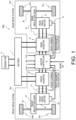
- FIG. 1 is a block diagram illustrating a main configuration of an electric vehicle system 100 to which an electric vehicle control method (control system) according to the present embodiment is applied.
- An electric vehicle in the present embodiment is an automobile that includes a drive motor 4 (electric motor) as a vehicle driving source and is capable of traveling by a driving force of the drive motor 4, and the electric vehicle includes an electric automobile and a hybrid automobile.
- the electric vehicle system 100 of the present embodiment applied to the electric vehicle includes two drive motors 4 (front drive motor 4f and rear drive motor 4r).
- front drive motor 4f and rear drive motor 4r two drive motors 4
- the configuration of the electric vehicle system 100 will be described in more detail.
- the electric vehicle system 100 includes a front drive system fds, a rear drive system rds, a battery 1, and a motor controller 2 (control unit).
- the front drive system fds is provided with various sensors and actuators for controlling the front drive motor 4f that drives front drive wheels 9f (left front drive wheel 9fL and right front drive wheel 9fR) that are front wheels.
- the rear drive system rds is provided with various sensors and actuators for controlling the rear drive motor 4r that drives rear drive wheels 9r (left rear drive wheel 9rL and right rear drive wheel 9rR) that are rear wheels.
- the front drive system fds and the rear drive system rds are individually controlled by the motor controller 2.
- the battery 1 functions as a power source that supplies (discharges) drive power to the drive motors 4 (front drive motor 4f and rear drive motor 4r), while it is connected to inverters 3 (front inverter 3f and rear inverter 3r) so as to be charged by receiving a supply of regenerative power from the drive motors 4 (front drive motor 4f and rear drive motor 4r).
- a generator 11 is an engine or a fuel cell, and generates electric power and supplies the electric power to the battery 1 when SOC (charge amount) of the battery 1 is less than a predetermined lower limit value.
- the motor controller 2 is, for example, a computer including a central processing unit (CPU), a read-only memory (ROM), a random access memory (RAM), and an input/output interface (I/O interface).
- the motor controller 2 constitutes a control device of the electric vehicle according to the present invention, and is a component including a program for executing a control method for the electric vehicle according to the present invention.
- the motor controller 2 receives, as digital signals, signals of various vehicle variables indicating vehicle states of accelerator position APO, a vehicle speed V, an operation amount of a brake pedal of a friction brake (brake operation amount BR), rotor phases ⁇ (front rotor phase of and rear rotor phase ⁇ r) of the drive motors 4, and currents Im (front motor current Imf and rear motor current Imr) of the drive motors 4.
- the motor controller 2 receives a signal from a mode switch that determines a traveling mode of the electric vehicle based on an operation of a driver.
- the traveling mode includes an accelerator mode in which almost no braking torque is generated even when an accelerator operation is canceled, and a one-pedal mode in which the electric vehicle can be stopped by generating a regenerative torque (regenerative current) that is a strong braking torque when the accelerator operation is canceled.
- a regenerative torque regenerative current
- the motor controller 2 generates a PWM signal for controlling each of the drive motors 4 based on a received signal.
- a drive signal for each of the inverters 3 is generated according to each of the generated PWM signals.
- the motor controller 2 receives SOC information from the battery 1, starts the generator 11 when the SOC is less than the predetermined lower limit value, and stops the generator 11 when the SOC reaches a predetermined upper limit value.
- Each of the inverters 3 includes two switching elements (for example, power semiconductor elements such as IGBTs and MOS-FETs) provided corresponding to the respective phases.
- the inverter 3 turns on/off the switching elements in response to a command from the motor controller 2, thereby converting or inversely converting a direct current supplied from the battery 1 into an alternating current, and adjusting a current supplied to the drive motor 4 to a desired value.
- Each of the drive motors 4 is configured as a three-phase AC motor.
- Each of the drive motors 4 (front drive motor 4f and rear drive motor 4r) generates a driving force by an alternating current supplied from the corresponding inverter 3 (front inverter 3f and rear inverter 3r), and transmits the driving force to the drive wheels 9 (front drive wheels 9f and rear drive wheels 9r) via a corresponding reduction gear 5 (front reduction gear 5f and rear reduction gear 5r) and a drive shaft 8 (front drive shaft 8f and rear drive shaft 8r).
- the drive motor 4 recovers kinetic energy of the electric vehicle as electric energy by generating regenerative power when the drive motor 4 rotates together with the drive wheels 9 during traveling of the electric vehicle.
- the inverter 3 converts an alternating current (regenerative power) generated during a regenerative operation into a direct current and supplies the direct current to the battery 1.
- Rotation sensors 6 (front rotation sensor 6f and rear rotation sensor 6r), which are angular velocity detection units (executing angular velocity detection step), detect the rotor phases ⁇ (front rotor phase ⁇ f and rear rotor phase ⁇ r ) of the drive motors 4, respectively, and output the rotor phases ⁇ to the motor controller 2.
- the rotation sensor 6 includes, for example, a resolver, an encoder, or the like.
- Current sensors 7 detect three-phase alternating currents (iu, iv, and iw) flowing through the respective drive motors 4. Since the sum of the three-phase alternating currents (iu, iv, and iw) is zero, currents of any two phases may be detected by the current sensor 7, and a current of the remaining one phase may be obtained by calculation.
- the current sensor 7 detect three-phase alternating currents (iuf, iv f , and iw f ) which are currents flowing through the front drive motor 4f and three-phase alternating currents (iu r , iv r , and iw r ) which are currents flowing through the rear drive motor 4r.
- FIG. 2 is a flowchart illustrating a basic process in the control device of the electric vehicle by the motor controller 2 of the present embodiment.
- the motor controller 2 is programmed to execute processes from step S201 to step S205 shown in FIG. 2 at a predetermined calculation cycle.
- step S201 the motor controller 2 performs a reception process of acquiring various parameters used for executing processes of step S202 and subsequent steps according to the following processes 1 to 3.
- the motor controller 2 acquires the accelerator position APO (%), the brake operation amount BR, the rotor phase ⁇ [rad], the three-phase alternating currents (iu, iv, and iw) [A] flowing through the drive motor 4, and a direct current voltage value Vdc [V] of the battery 1 from an accelerator position sensor (not shown) and the above sensors. In addition, the motor controller 2 acquires a mode switch signal.
- the motor controller 2 acquires previous values of motor torque command values (front motor torque command value Tmf and rear motor torque command value Tmr), which will be described later, stored in an internal memory.
- the motor controller 2 calculates, based on the respective parameters acquired according to the above "1.", a motor electric angular velocity ⁇ e [rad/s], a motor rotation speed ⁇ m [rad/s], a motor rotation speed N m [rpm], and a wheel speed ⁇ w [km/h].
- the motor controller 2 time-differentiates the rotor phase ⁇ (front rotor phase ⁇ f and rear rotor phase ⁇ r ) to obtain the motor electric angular velocity ⁇ e (front motor electric angular velocity ⁇ ef and rear motor electric angular velocity ⁇ er ).
- the motor controller 2 calculates the motor rotation speed ⁇ m (front motor rotation speed ⁇ mf and rear motor rotation speed ⁇ mr ), which is a mechanical angular velocity of the drive motor 4, by dividing the motor electric angular velocity ⁇ e by the number of pole pairs of the drive motor 4.
- a relation between the motor rotation speed ⁇ m and a rotation speed of the drive shaft 8 as a drive shaft is appropriately determined according to a gear ratio of the reduction gear 5. That is, the motor rotation speed ⁇ m is a speed parameter correlated with the rotation speed of the drive shaft 8.
- the motor controller 2 calculates the motor rotation speed N m (front motor rotation speed N mf and rear motor rotation speed N mr ) by multiplying the motor rotation speed ⁇ m by a unit conversion coefficient (60/2n).
- the motor controller 2 multiplies the front motor rotation speed ⁇ mf by a tire dynamic radius R, and calculates, based on a value obtained by the multiplication and a gear ratio of the front reduction gear 5f, a left front motor rotation speed ⁇ wFL and a right front motor rotation speed ⁇ wfR .
- the motor controller 2 multiplies the rear motor rotation speed ⁇ mr by the tire dynamic radius R, and calculates, based on a value obtained by the multiplication and a gear ratio of a final gear of the rear reduction gear 5r, a left rear motor rotation speed ⁇ wrL and a right rear motor rotation speed ⁇ wrR .
- a unit conversion coefficient (3600/ 1000) is applied to the wheel speed ⁇ w thus obtained, and a unit [m/s] of the wheel speed ⁇ w is converted into [km/h].
- the left front motor rotation speed ⁇ wfL , the right front motor rotation speed ⁇ wfR , the left rear motor rotation speed ⁇ wrL , and the right rear motor rotation speed ⁇ wrR may be directly detected by sensors, respectively.
- the vehicle speed V is obtained from a sensor such as a GPS, or, for example, is calculated as described above based on a wheel speed by selecting a lower rotation speed of the rotation speeds ( ⁇ mf and ⁇ mr ) during acceleration, selecting a higher rotation speed of the rotation speeds ( ⁇ mf and ⁇ mr ) during deceleration, or selecting either one of the rotation speeds ( ⁇ mf and ⁇ mr ) when the electric vehicle is traveling at a substantially constant speed.
- FIG. 3 is a diagram showing an example of an accelerator position-torque table in the accelerator mode.
- FIG. 4 is a diagram showing an example of an accelerator position-torque table in the one-pedal mode.
- the motor controller 2 sets a total torque target value Tm1. Specifically, when a driver selects the accelerator mode as the traveling mode of the electric vehicle, the total torque target value Tm1 is set by referring to the accelerator position APO-torque table shown in FIG. 3 , which represents one aspect of driving force characteristics of the accelerator mode calculated according to the accelerator position APO and the motor rotation speed ⁇ m received in step S201.
- the total torque target value Tm1 is set by referring to the accelerator position APO-torque table shown in FIG. 4 , which represents one aspect of driving force characteristic of the one-pedal mode calculated according to the accelerator position APO and the motor rotation speed ⁇ m received in step S201.
- the accelerator position APO is set to 1/8, it can be seen that motor torques become negative for almost all the motor rotation speeds (vehicle speed V), and a braking torque accompanied by a regenerative current is generated.
- step S203 the motor controller 2 executes a torque limiting process. Details of the torque limiting process will be described later.
- step S204 the motor controller 2 executes a current command value calculation process. Specifically, the motor controller 2 calculates a dq-axis current target value (i d *, i q *) with reference to a predetermined table based on the front motor torque command value Tmf (or front motor torque command value Tmf), the rear motor torque command value Tmr, the front motor rotation speed ⁇ mf , and the rear motor rotation speed ⁇ mr calculated in step S203, and the direct current voltage value V dc acquired in step S201.
- a dq-axis current target value i d *, i q *
- the motor controller 2 calculates a front dq-axis current target value (i df *, i qf *), which is a dq-axis current target value (i d *, i q *) set for the front drive motor 4f, and a rear dq-axis current target value (i dr *, i qr *), which is a dq-axis current target value (i d *, i q *) set for the rear drive motor 4r.
- step S205 the motor controller 2 executes a current control calculation process. Specifically, the motor controller 2 first calculates a dq-axis current value (i d , i q ) based on values of the three-phase alternating currents (iu, iv, and iw) and the rotor phase ⁇ acquired in step S201. Next, the motor controller 2 calculates a dq-axis voltage command value (v d , v q ) based on a deviation between the dq-axis current value (i d , i q ) and the dq-axis current target value (i d *, i q *) obtained in step S204.
- the motor controller 2 calculates a front dq-axis voltage command value (v df , v qf ) which is a dq-axis voltage command value (v d , v q ) set for the front drive motor 4f and a rear dq-axis voltage command value (v dr , v qr ) which is a dq-axis voltage command value (v d , v q ) set for the rear drive motor 4r.
- the motor controller 2 calculates three-phase alternating voltage command values (vu, vv, and vw) based on the dq-axis voltage command value (v d , v q ) and the rotor phase ⁇ .
- the motor controller 2 calculates front three-phase alternating voltage command values (vu f , vv f , and vw f ), which are three-phase alternating voltage command values (vu, vv, and vw) set for the front drive motor 4f, and rear three-phase alternating voltage command values (vu f , vv f , and vw f ), which are three-phase alternating voltage command values (vu, vv, and vw) set for the rear drive motor 4r.
- the motor controller 2 obtains a PWM signal (tu, tv, and tw) [%] based on the calculated three-phase alternating voltage command values (vu, vv, and vw) and the direct current voltage value Vdc.
- a PWM signal (tu, tv, and tw) [%] based on the calculated three-phase alternating voltage command values (vu, vv, and vw) and the direct current voltage value Vdc.
- the motor controller 2 transmits the front motor torque command value Tmf to the front inverter 3f via the PWM signal, and transmits the rear motor torque command value Tmr to the rear inverter 3r via the PWM signal.
- the front motor torque command value Tmf can be functioned as a front braking torque by the accelerator operation and the rear motor torque command value Tmr can be functioned as a rear braking torque by the accelerator operation.
- distribution torques for example, 7: 3 to the front wheel and the rear wheel are set in advance such that a relation between a steering operation and the actual steering of the electric vehicle is appropriate.
- the front wheel is generally steered.
- the torque limiting process is executed on the front drive motor 4f and the rear drive motor 4r.
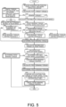
- FIG. 5 is a flowchart illustrating the torque limiting process.
- FIG. 6 is a map showing a relation between the brake operation amount BR and a threshold of a slip tendency degree ST of the rear wheel.
- FIG. 7 is a map showing a relation between the brake operation amount BR and a threshold of a slip ratio S of the front wheel.
- FIG. 8 is a map for performing a front braking torque control based on the slip ratio S and a change amount in the slip ratio S ( ⁇ slip ratio).
- step S301 the motor controller 2 receives the accelerator position APO, the vehicle speed V, and the brake operation amount BR, and in step S302, the motor controller 2 calculates the total torque target value Tm1.
- Step S301 is included in step S201, and step S302 is included in step S202.
- step S303 the motor controller 2 determines whether the total torque target value Tm1 is the braking torque. If NO, the process proceeds to step S304, and if YES, the process proceeds to step S305. Whether the total torque target value Tm1 is the braking torque is determined, for example, by comparing the information of the accelerator position and the motor rotation speed with the map of FIG. 3 or FIG. 4 , or by determining whether the front current sensor 7f or the rear current sensor 7r detects a regenerative current. In particular, when the one-pedal mode is selected as the traveling mode, the braking torque is significantly generated.
- step S304 the motor controller 2 determines that the total torque target value Tm1 is the driving torque, and if the front braking torque control or rear braking torque limiting processes (A, B, and C), which will be described later, are being executed, the motor controller 2 cancels all of these processes. Then, the motor controller 2 multiplies, for example, the total torque target value Tm1 by front and rear driving force distribution gains Kf (0 ⁇ Kf (for example, 0.7) ⁇ 1) and (1 - Kf) (for example, 0.3) to obtain the front motor torque command value Tmf and the rear motor torque command value Tmr, thereby determining a distribution torque of the front wheel and a distribution torque of the rear wheel, and uses these values in step S204.
- front and rear driving force distribution gains Kf (0 ⁇ Kf (for example, 0.7) ⁇ 1
- (1 - Kf) for example, 0.3
- step S305 the motor controller 2 determines that the total torque target value Tm1 is the braking torque, and calculates the rear motor torque command value Tmr (rear braking torque) by multiplying the total torque target value Tm1 by (1 - Kf).
- step S306 the motor controller 2 determines whether the front braking torque control, which will be described later, is being executed. If NO, the process proceeds to step S307, and if YES, the process proceeds to step S310.
- step S307 the motor controller 2 calculates the slip tendency degree ST of the rear wheel.
- the slip tendency degree ST of the rear wheel is calculated as a ratio of a change amount in a rotation speed of the rear drive motor 4r to the rear braking torque (change amount in rotation speed of rear drive motor 4r/rear braking torque).
- a magnitude of the rear braking torque is calculated based on a value of the rear motor torque command value Tmr or a magnitude of a regenerative current detected by the rear current sensor 7r.
- the change amount in the rotation speed of the rear drive motor 4r is calculated by subtracting, from the calculated rear motor rotation speed ⁇ mr , a rotation speed (corresponding to a latest past rotation speed) obtained through a low-pass filter, which is the rear motor rotation speed ⁇ mr .
- the slip tendency degree ST of the rear wheel may be calculated as the change amount/the rear braking torque by directly detecting the rotation speed of the rear drive motor 4r with a sensor and using a change amount in the rotation speed.
- the slip tendency degree ST of the rear wheel may be calculated as a slip ratio/a rear braking torque by calculating a wheel speed based on wheel speed pulse information of left and right rear wheels detected by an ABS controller (motor controller 2) that executes ABS control described later and using an average slip ratio of the left and right rear wheels.
- ABS controller motor controller 2
- step S308 the motor controller 2 determines whether the slip tendency degree ST of the rear wheel exceeds a threshold STth with reference to the map of FIG. 6 . If NO, the process proceeds to step S313, and if YES, the process proceeds to step S309.
- FIG. 6 is a map for making it more difficult to execute the control of step S309, which will be described later, as the brake operation amount BR of a driver increases, and for preferentially executing the braking by a brake operation.
- the brake operation amount BR is zero
- the threshold STth is the minimum value STthmin, but the threshold STth monotonically increases as the brake operation amount BR increases.
- ABS anti-lock brake system
- step S309 the motor controller 2 executes the rear braking torque limiting process A (hereinafter, referred to as process A), which is a distribution torque changing process.
- process A a distribution torque changing process.
- a distribution torque (rear braking torque) to the rear drive motor 4r is decreased, and a distribution torque (front braking torque) to the front drive motor is increased by that amount.
- a first torque correction value for obtaining a front braking torque at which no slip occurs in the rear wheel may be prepared in advance, the first torque correction value may be added to the rear motor torque command value Tmr, and the first torque correction value may be subtracted from the front motor torque command value Tmf.
- the control is performed such that the distribution torque after change is obtained with a predetermined time constant.
- step S306 the motor controller 2 proceeds to step S310.
- step S310 the motor controller 2 determines whether the distribution torques between the front wheel and the rear wheel are within a specified value. If YES, the process proceeds to step S311, and if NO, the process proceeds to step S312.
- the specified value specifies a maximum value of the distribution torque of the rear wheel, and for example, the distribution torques of the front wheel and the rear wheel are 0.7: 0.3.
- the specified value for example, 0.3
- the steering characteristics of the electric vehicle becomes oversteer, and when the steering operation is performed during braking of the electric vehicle, the electric vehicle may spin. Therefore, in order to avoid this, the specified value is set as an upper limit of the distribution torque of the rear wheel.
- step S311 the motor controller 2 executes the rear braking torque limiting process B (hereinafter, referred to as process B).
- process B the rear braking torque limiting process B
- the rear braking torque to be applied to the rear drive motor 4r is reduced in advance (in feedforward manner) to avoid the slip of the rear wheel.
- step S311 is executed after step S309 is executed.
- the process B is different from the process A in that a second torque correction value that is a rear braking torque (negative torque) at which no slip occurs in the rear wheel is prepared in advance, and the second torque correction value is added to the rear motor torque command value Tmr.
- step S312 the motor controller 2 executes the rear braking torque limiting process C (hereinafter, referred to as process C).
- process C limits the rear braking torque to be applied to the rear drive motor 4r such that the distribution torque of the rear wheel does not exceed the specified value, and controls the rear motor torque command value Tmr such that a distribution torque with respect to the front motor torque command value Tmf determined in step S319, which will be described later, becomes the specified value (or becomes smaller than specified value).
- step S312 the motor controller 2 proceeds to step S313.
- step S313 the motor controller 2 determines the rear motor torque command value Tmr calculated in step S308 (NO), step S309, step S311, and step S312 as the rear braking torque to be applied to the rear drive motor 4r (rear wheel), and uses this value in step S204 ( FIG. 2 ).
- step S314 the motor controller 2 calculates the front motor torque command value Tmf (front braking torque) as a front wheel distribution torque by multiplying the total torque target value Tm1 obtained in step S302 by the driving force distribution gain Kf (initial value). However, when the process A of step S309 is executed, the front motor torque command value Tmf is calculated based on the distribution torque in the process A.
- step S315 the motor controller 2 calculates the slip ratio S of the front wheel.
- the slip ratio S of the front wheel is calculated according to (rotation speed of rear wheel - rotation speed of front wheel) / (rotation speed of rear wheel) on the assumption that the rear wheel is not slipping.
- step S316 the motor controller 2 determines whether the slip ratio S of the rear wheel exceeds a threshold Sth with reference to the map of FIG. 7 . If NO, the process proceeds to step S317, and if YES, the process proceeds to step S318.
- FIG. 7 is a map for making it more difficult to execute the control of step S318, which will be described later, as the brake operation amount BR of a driver increases, and for preferentially executing the braking by a brake operation.
- the brake operation amount BR is zero
- the threshold Sth is the minimum value Sthmin, but the threshold Sth monotonically increases as the brake operation amount BR increases.
- step S317 the motor controller 2 determines the front motor torque command value Tmf calculated in step S314 as the front braking torque to be applied to the front drive motor 4f (front wheel), and uses this value in step S204 ( FIG. 2 ).
- step S318 the motor controller 2 executes the front braking torque control for preventing slip of the front wheel.
- the motor controller 2 calculates the ⁇ slip ratio (change amount in slip ratio S) based on a difference between a current slip ratio S calculated in step S315 and a value (corresponding to latest past slip ratio S) obtained through a low-pass filter as the slip ratio S.
- ⁇ slip ratio change amount in slip ratio S
- the ⁇ slip ratio is positive, it means that the slip of the front wheel tends to decrease, and when the ⁇ slip ratio is negative, it means that the slip of the front wheel tends to increase.
- the motor controller 2 refers to the map of FIG. 8 , and calculates, based on the slip ratio S and the ⁇ slip ratio, addition torques ( ⁇ +, ⁇ -) to be added to the previous value of the front motor torque command value Tmf (front braking torque) in the next step S319 such that the ⁇ slip ratio of the front wheel becomes zero or a positive value (such that the slip is eliminated).
- the value of the front motor torque command value Tmf (front braking torque) is updated by using the front motor torque command value Tmf (front braking torque) calculated in step S314 as an initial value and adding the addition torque ( ⁇ +) or the addition torque ( ⁇ -) as needed.
- the addition torque ( ⁇ +) increases the front motor torque command value Tmf and decreases the braking torque of the front wheel.
- the addition torque ( ⁇ -) decreases the front motor torque command value Tmf and increases the braking torque of the front wheel.
- step S319 the motor controller 2 calculates (updates) the front motor torque command value Tmf by adding the addition torque ( ⁇ +) or the addition torque ( ⁇ -) calculated in step S318 to the previous value of the front motor torque command value Tmf.
- step S320 the motor controller 2 determines the updated front motor torque command value Tmf as the front braking torque to be applied to the front drive motor 4f (front wheel), and uses this value in step S204 ( FIG. 2 ).
- step S321 the motor controller 2 compares a current value of the front motor torque command value Tmf with the front motor torque command value Tmf calculated in step S314, and determines whether the front motor torque command value Tmf matches the front motor torque command value Tmf (front wheel distribution torque) for a specified time. If YES, the process proceeds to step S322, and if NO, the process proceeds to step S204 ( FIG. 2 ).
- step S322 the motor controller 2 determines that an increasing tendency of the slip ratio S of the front wheel is eliminated and an original front braking torque (front braking torque related to one-pedal control) can be applied to the front drive motor 4f, cancels the front braking torque control, and proceeds to step S204 ( FIG. 2 ).
- the determination in step S316 is set to NO until the next braking torque is applied to the front wheel and the rear wheel.
- FIG. 9 is a time chart when the process A is executed.
- FIG. 9 shows a time chart of a total torque (front torque and rear torque) and rotation speeds of the drive wheels 9 (right front drive wheel, left front drive wheel, right rear drive wheel, and left rear drive wheel) in a case where a driver selects the one-pedal mode as the traveling mode, and a slip is detected in a rear wheel (for example, right rear drive wheel) when the driver releases an accelerator pedal after depressing the accelerator pedal with a predetermined accelerator position on a wet road surface with reduced friction force, for example.
- a total torque front torque and rear torque
- rotation speeds of the drive wheels 9 right front drive wheel, left front drive wheel, right rear drive wheel, and left rear drive wheel
- a slip is detected in a rear wheel (for example, right rear drive wheel) when the driver releases an accelerator pedal after depressing the accelerator pedal with a predetermined accelerator position on a wet road surface with reduced friction force, for example.
- the front torque when the front torque is positive, it is a front driving torque for accelerating the electric vehicle, and when the front torque is negative, it is the front braking torque for braking (deceleration) of the electric vehicle.
- the rear torque when the rear torque is positive, it is a rear driving torque for accelerating the electric vehicle, and when the rear torque is negative, it is the rear braking torque for braking (deceleration) of the electric vehicle.
- step S303 in FIG. 5 when the motor controller 2 determines that the total torque has shifted to the braking torque (YES in step S303 in FIG. 5 ), the motor controller 2 distributes the total torque to the front torque (front braking torque) of the front wheel and the rear torque (rear braking torque) of the rear wheel at a predetermined distribution (for example, 7: 3) (step S305 in FIG. 5 ). At this time, the rotation speed of the drive wheel 9 also starts to gradually decrease.
- a predetermined distribution for example, 7: 3
- the determination in S306 of FIG. 5 is NO, and the process B of step S311 and the process C of step S312 are not performed.
- the front braking torque (convergence value) and the rear braking torque (convergence value) are controlled by one-pedal control using an accelerator operation amount (accelerator position APO) or the like as a received value.
- the motor controller 2 determines that the slip tendency degree ST of the right rear drive wheel 9 exceeds the threshold STthmin (STth when the driver is depressing the brake pedal), and turns on a rear wheel slip detection flag. As a result, the determination in step S308 of FIG. 5 becomes YES.
- step S309 of FIG. 5 the motor controller 2 executes the process A of step S309 of FIG. 5 .
- the distribution torques between the front wheel and the rear wheel are changed from 0.6: 0.4 to 0.8: 0.2, for example, and in step S313, the rear braking torque to be applied to the rear drive motor 4r is determined based on the changed distribution torque of the rear wheel.
- step S317 the front braking torque to be applied to the front drive motor 4f is determined based on the changed distribution torque.
- the rear braking torque decreases monotonously and the front braking torque increases monotonously from time t3 to time t4, and between time t3 to time t4, the distribution torques between the front wheel and the rear wheel are changed from 7: 3 to 8: 2, for example.
- the rear torque (rear braking torque) determined by the process A of step S309 in FIG. 5 is set to a braking torque that does not cause a slip on the rear wheel even on a road surface where a friction force is reduced due to flooding as described above. Therefore, by executing the process A of step S309 of FIG. 5 , the rotation speed of the right rear drive wheel 9 converges to the rotation speed of another drive wheel 9, and the slip is eliminated.
- a curve B (broken line) represents the rotation speed when no slip occurs in the right rear drive wheel.
- a curve A solid line representing the rotation speed of the right rear drive wheel 9 converges to the curve B after the time t3.
- the behavior of the drive wheel 9 in which no slip occurs after the time t3 does not change even if the process A is executed.
- step S308 in FIG. 5 When the determination in step S308 in FIG. 5 is still NO at the time t3, the rotation speed of the right rear drive wheel 9 rapidly decreases thereafter as shown by a curve C (broken line), and the rotation is finally locked.
- FIG. 10 is a time chart when the process B and the front braking torque control are executed after the process A is executed.
- FIG. 10 is a time chart when a slip occurs in the front wheel after the process A is executed. Therefore, the total torque (front torque and rear torque) and the rotation speeds of the drive wheels 9 (right front drive wheel, left front drive wheel, right rear drive wheel, and left rear drive wheel) shown in FIG. 10 change in the same manner as in the time chart of FIG. 9 until time t4. In FIG. 10 , curves indicating the rotation speeds of the drive wheels 9 (left front drive wheel and left rear drive wheel) are not shown.
- the motor controller 2 executes the process A and the distribution torque of the front torque (front braking torque) increases, for example, at time t4, the rotation speed of the right front drive wheel 9 starts to become lower than the rotation speeds of the other drive wheels 9 (left front drive wheel and left rear drive wheel), and a slip occurs.
- the motor controller 2 determines that the slip ratio S of the right front drive wheel 9 exceeds the threshold Sthmin (Sth when the driver is depressing the brake pedal), and turns on a front wheel slip detection flag. As a result, the determination in step S316 shown in FIG. 5 becomes YES, and the front braking torque control in step S318 is executed.
- the motor controller 2 determines YES in step S306 and executes the process B in step S311 on the condition that the determination in step S310 is YES. That is, at the time t5, the front braking torque control for the front wheel and the process B for the rear wheel are executed substantially simultaneously.
- the cause of the slip of the front wheel at the time t5 includes a case where the front wheel runs onto a road surface with even lower friction ratio at the time t5, in addition to a case where the distribution torque of the front torque (front braking torque) increases. Therefore, since the rear wheel runs onto the road surface after the front wheel runs onto the road surface, the slip (slip tendency degree ST) of the rear wheel may increase again. Therefore, when the front braking torque control is executed, it is preferable to also execute the process B (or process C). However, the process B does not necessarily have to be executed, and for example, the driver may be allowed to select whether to execute the process B.
- the slip ratio S of the front wheel is calculated according to (rotation speed of rear wheel - rotation speed of front wheel) / (rotation speed of rear wheel). Therefore, by reliably avoiding the slip of the rear wheel by the process B, the reliability of the slip ratio S of the front wheel can be enhanced, and the front braking torque control can be reliably executed.
- the front braking torque control increases the front torque (decreases the front braking torque) such that at least the slip ratio S of the front wheel does not tend to increase, and may be overshooting or undershooting as shown in FIG. 10 .
- the slip of the right front drive wheel 9 is eliminated in such a manner that the rotation speed (curve D) of the right front drive wheel 9 approaches the rotation speed (curve A) of the right rear drive wheel 9 by executing the front braking torque control after the time t5.
- a curve E (broken line) indicating the rotation speed of the right front drive wheel 9 represents a case where no slip occurs in the front wheel and the front braking torque control is not executed.
- a curve F indicates a case where the front braking torque control is not executed even when a slip occurs in the right front drive wheel 9, and in this case, the rotation speed of the right front drive wheel 9 rapidly decreases and the rotation is locked.
- a curve B and a curve C are the same as the curve B and the curve C in FIG. 9 , respectively.
- the curve A representing the rotation speed of the right rear drive wheel 9 does not converge to the curve B, and monotonously decreases in a state where the rotation speed is higher than that of the curve B and a slope is gentler than that of the curve B.
- the curve D representing the rotation speed of the right front drive wheel 9 does not converge to the curve E, and monotonously decreases in a state where the rotation speed is higher than that of the curve E and a slope is gentler than that of the curve E.
- the front braking torque control (and process B) is executed without executing the process A.
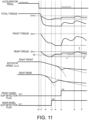
- FIG. 11 is a time chart when the rear braking torque limiting process B, the rear braking torque limiting process C, and the front braking torque control are executed after the rear braking torque limiting process A is executed.
- FIG. 11 is a time chart when the process C is executed as a result of the distribution torque of the rear torque (rear braking torque) exceeding a specified value (for example, 0.3) due to the front wheel running onto a road surface with even lower friction force and the front motor torque command value Tmf increasing (front braking torque decreasing) even though the process A, the front braking torque control, and the process B are executed as in the time chart shown in FIG. 10 .
- a specified value for example, 0.3
- a curve G represents the rear torque (rear braking torque) when the process A, the front braking torque control, the process B, and the process C are executed.
- a curve H represents the rear torque (rear braking torque) when the process C is executed without executing the process B after the process A and the front braking torque control are executed.
- step S310 of FIG. 5 the motor controller 2 compares the rear motor torque command value Tmr calculated by the process B (process A when process B is not executed) with the rear motor torque command value Tmr obtained by the process C, and selects the higher value (the smaller braking torque).
- the rear motor torque command value Tmr calculated by the process C is applied as the rear torque (rear braking torque).
- the value of the rear motor torque command value Tmr is controlled so as to maintain, for example, 0.7: 0.3, so that the rear motor torque command value Tmr (rear braking torque) does not become zero.
- the rear motor torque command value Tmr calculated by the process B is applied as the rear torque (rear braking torque).
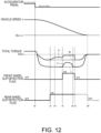
- FIG. 12 is a time chart when the electric vehicle is braked and stopped and the front braking torque control and the like are canceled. Similar to FIG. 10 , FIG. 12 shows a time chart in a case where after the process A, the front braking torque control, and the process B are executed during deceleration, the friction force of the road surface is restored by getting out of the wet road surface, an original braking torque can be applied to the front wheel (rear wheel), and the electric vehicle is stopped.
- the total torque (front torque and rear torque) and the rotation speeds of the drive wheels 9 change in the same manner as in the time chart of FIG. 10 until the time t5.
- curves indicating the front torque and the rotation speeds of the drive wheels 9 are not shown.
- a curve J represents a total torque in which the front braking torque control and the process B are reflected
- a curve K represents a rear torque component in the total torque
- a curve L is a total torque determined by the one-pedal control, and matches the curve J at times other than between the time t5 and time t8. Further, a curve M is a rear torque component in the total torque represented by the curve L, and matches the curve K at times other than between the time t3 and time t9.
- the change between the time t5 and the time t8 indicates that the total torque increases (the braking torque decreases) due to the execution of the front braking torque control and the process B.
- the front motor torque command value Tmf set by the front braking torque control decreases (the front braking torque increases), and at the time t8, the front torque (front motor torque command value Tmf) matches the front torque (front motor torque command value Tmf) determined by the one-pedal control.
- the total torque matches the total torque determined by the one-pedal control.
- the front motor torque command value Tmf is a value less than the front motor torque command value Tmf determined by the one-pedal control by a difference between the torques of the curve K and the curve M.
- a period between the time t8 and the time t9 is the specified time of step S321 of FIG. 5 . Therefore, at the time t9, the motor controller 2 determines that the slip of the front wheel is eliminated, and turns off the front wheel slip detection flag.
- step S316 of FIG. 5 becomes NO, and in step S317, the front torque is switched from the front motor torque command value Tmf determined in step S320 to the front motor torque command value Tmf determined by the one-pedal control.
- step S306 in FIG. 5 When the determination in step S306 in FIG. 5 is NO, the process B in step S311 is canceled, and when the determination in step S308 is NO, the process A in step S309 is also canceled. Therefore, after the time t9, the total torque shown by the curve J in FIG. 12 matches the curve L, and the rear torque component shown by the curve K matches the curve M.
- the rear torque component shown by the curve K changes stepwise, but may gradually change to the position of the curve M.
- the front torque may also gradually change from the front motor torque command value Tmf determined in step S320 to the front motor torque command value Tmf determined by the one-pedal control.
- the motor controller 2 can turn off the rear wheel slip detection flag at the time t9, the time t10, or when the next braking torque is generated in the electric vehicle.
- the front braking torque control (and processes B and C) is executed without executing the process A.
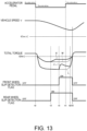
- FIG. 13 is a time chart when the electric vehicle re-accelerates without stopping after braking and the front braking torque control and the like are canceled.
- FIG. 13 is a time chart when the process A and the front braking torque control are executed during deceleration (here, process B is not executed), and then the total torque is switched from the braking torque (negative torque) to the driving torque (positive torque) by the driver depressing the accelerator pedal.
- the motor controller 2 turns on the front wheel slip detection flag by detecting a slip of the front wheel, and executes the front braking torque control.
- the total torque (curve J) reflecting the process A and the front braking torque control matches the total torque determined by the one-pedal control (or the total torque corresponding to the total regenerative current generated by the front drive motor 4f and the rear drive motor 4r) (curve L).
- the total torque becomes a predetermined value (for example, zero), and thereafter, the total torque becomes the driving torque, and the electric vehicle resumes acceleration.
- a predetermined value for example, zero
- the total torque becomes the driving torque, and the electric vehicle resumes acceleration.
- the motor controller 2 can turn off the front wheel slip detection flag.
- the rear wheel slip detection flag can also be turned off at the time t13, and may be turned off when the next braking torque is generated.
- step S303 of FIG. 5 the determination in step S303 of FIG. 5 becomes NO. Therefore, the motor controller 2 can set the front motor torque command value Tmf and the rear motor torque command value Tmr to values determined by the one-pedal control by canceling all of the process A, the process B, the process C, and a front regeneration limiting process (step S304).
- a torque limiting process for reducing the front braking torque and the rear braking torque is executed when a slip of the front wheel is detected
- distribution torque changing process for increasing the front braking torque while maintaining a sum of the front braking torque and the rear braking torque is executed when a slip of the rear wheel is detected.
- the rear braking torque is set to be lower than the rear braking torque at the time of a distribution torque changing process (process B). That is, when the slip of the front wheel is detected, the rear motor torque command value Tmr is set to be higher than the rear motor torque command value Tmr at the time of the distribution torque changing process. Since the rear wheel runs onto a road surface where the front wheel runs onto, if a slip is detected in the front wheel, a slip may be detected in the rear wheel thereafter, and this may occur even after the distribution torque changing process (process A) is executed.
- the slip of the rear wheel can be reliably avoided, and the reliability of the slip ratio S of the front wheel calculated based on a rotation speed of the rear wheel and a rotation speed of the front wheel can be enhanced.
- the torque limiting process is executed in preference to the one-pedal control, and the torque limiting process is canceled when the front braking torque related to the front braking torque control reaches the front braking torque related to the one-pedal control.
- distribution torques of the front drive motor 4f and the rear drive motor 4r can be constant after a friction force of the road surface is restored, and thus a pitch during braking of the electric vehicle can be stabilized.
- the torque limiting process is executed in preference to the one-pedal control, and the torque limiting process is canceled when the front braking torque related to the one-pedal control reaches a predetermined value (for example, zero).
- the electric vehicle can be stably re-accelerated.
- the torque limiting process and the distribution torque changing process are canceled.
- the torque limiting process and the distribution torque changing process can be easily and reliably canceled.
- the slip (slip tendency degree ST) of the rear wheel is detected based on a ratio of a change amount in a rotation speed of the rear drive motor 4r to the rear braking torque.
- the slip of the rear wheel can be quickly detected independently of the front wheel.
- the slip (slip tendency degree ST) of the rear wheel is detected by whether the ratio of the change amount in the rotation speed of the rear drive motor 4r to the rear braking torque exceeds a predetermined threshold (STth), and the threshold (Stth) is increased as an operation amount of a friction brake (brake operation amount BR) increases.
- the electric vehicle control system is an electric vehicle control system including the front drive motor 4f that drives a front wheel, the rear drive motor 4r that drives a rear wheel, and a control unit (motor controller 2) that drives and controls the front drive motor 4f and the rear drive motor 4r, in which the control unit (motor controller 2) causes an electric vehicle to brake by applying a front braking torque to the front drive motor 4f and applying a rear braking torque to the rear drive motor 4r, and during braking, the control unit (motor controller 2) executes a torque limiting process (process B, process C, and front braking torque control) that reduces the front braking torque and the rear braking torque when a slip of the front wheel is detected, and executes a distribution torque changing process (process A) that increases the front braking torque while maintaining a sum of the front braking torque and the rear braking torque when a slip of the rear wheel is detected.
- a torque limiting process process B, process C, and front braking torque control
Landscapes
- Engineering & Computer Science (AREA)
- Mechanical Engineering (AREA)
- Transportation (AREA)
- Combustion & Propulsion (AREA)
- Chemical & Material Sciences (AREA)
- Power Engineering (AREA)
- Automation & Control Theory (AREA)
- Physics & Mathematics (AREA)
- Electromagnetism (AREA)
- Life Sciences & Earth Sciences (AREA)
- Sustainable Development (AREA)
- Sustainable Energy (AREA)
- Electric Propulsion And Braking For Vehicles (AREA)
- Control Of Driving Devices And Active Controlling Of Vehicle (AREA)
Applications Claiming Priority (1)
| Application Number | Priority Date | Filing Date | Title |
|---|---|---|---|
| PCT/JP2020/040539 WO2022091272A1 (ja) | 2020-10-28 | 2020-10-28 | 電動車両の制御方法、及び電動車両の制御システム |
Publications (3)
| Publication Number | Publication Date |
|---|---|
| EP4253179A1 EP4253179A1 (en) | 2023-10-04 |
| EP4253179A4 EP4253179A4 (en) | 2024-01-03 |
| EP4253179B1 true EP4253179B1 (en) | 2024-10-09 |
Family
ID=81383783
Family Applications (1)
| Application Number | Title | Priority Date | Filing Date |
|---|---|---|---|
| EP20959790.5A Active EP4253179B1 (en) | 2020-10-28 | 2020-10-28 | Method for controlling electric vehicle and system for controlling electric vehicle |
Country Status (6)
| Country | Link |
|---|---|
| US (1) | US11932138B2 (https=) |
| EP (1) | EP4253179B1 (https=) |
| JP (1) | JP7435818B2 (https=) |
| CN (1) | CN116368046B (https=) |
| MX (1) | MX2023004810A (https=) |
| WO (1) | WO2022091272A1 (https=) |
Families Citing this family (8)
| Publication number | Priority date | Publication date | Assignee | Title |
|---|---|---|---|---|
| JP7827493B2 (ja) * | 2022-03-10 | 2026-03-10 | 株式会社Subaru | 車両の制御装置及びコンピュータプログラム |
| CN115891677B (zh) * | 2022-11-14 | 2025-05-23 | 华为数字能源技术有限公司 | 一种电动车辆动力系统的控制装置及其相关设备 |
| DE102023117545A1 (de) * | 2023-07-03 | 2025-01-09 | Zf Active Safety Gmbh | Verfahren zum Steuern von Bremsvorgängen eines Brake-by-Wire-Bremssystems sowie Brake-by-Wire-Bremssystem |
| US12545118B1 (en) * | 2023-08-30 | 2026-02-10 | Zoox, Inc. | Torque distribution-based deceleration |
| DE102024201861A1 (de) * | 2024-02-29 | 2025-09-04 | Robert Bosch Gesellschaft mit beschränkter Haftung | Verfahren zum Betreiben eines Kraftfahrzeugs, Computerprogrammprodukt, Speichermedium, Computereinrichtung |
| CN119176033A (zh) * | 2024-09-30 | 2024-12-24 | 华为数字能源技术有限公司 | 一种电机控制器、动力总成及电动车辆防滑控制的方法 |
| CN119160009B (zh) * | 2024-10-31 | 2025-09-09 | 东风汽车集团股份有限公司 | 一种双电机驱动桥的扭矩控制方法及装置 |
| CN119568153A (zh) * | 2024-11-25 | 2025-03-07 | 华为数字能源技术有限公司 | 用于车辆原地脱困的控制方法、车辆控制器和电动车辆 |
Family Cites Families (41)
| Publication number | Priority date | Publication date | Assignee | Title |
|---|---|---|---|---|
| JP3951480B2 (ja) * | 1998-11-25 | 2007-08-01 | トヨタ自動車株式会社 | 車両の回生制動制御装置 |
| JP3646632B2 (ja) * | 2000-08-10 | 2005-05-11 | マツダ株式会社 | 車両の走行制御装置 |
| JP3811372B2 (ja) * | 2001-05-30 | 2006-08-16 | トヨタ自動車株式会社 | 車輌の制動力制御装置 |
| US7409280B2 (en) * | 2004-01-15 | 2008-08-05 | Nissan Motor Co., Ltd. | Vehicle braking control apparatus |
| JP2006025485A (ja) * | 2004-07-06 | 2006-01-26 | Nissan Motor Co Ltd | 車両の制駆動力制御装置 |
| US7441845B2 (en) * | 2004-09-13 | 2008-10-28 | Ford Global Technologies, Llc | Method for operating multiple axle regenerative braking in an automotive vehicle |
| US7322659B2 (en) * | 2005-08-04 | 2008-01-29 | Gm Global Technology Operations, Inc. | Method and system for brake distribution in a regenerative braking system |
| JP4765487B2 (ja) * | 2005-08-29 | 2011-09-07 | 株式会社アドヴィックス | 車両用ブレーキ装置 |
| US20070108838A1 (en) * | 2005-11-14 | 2007-05-17 | Ford Global Technologies, Llc | Regenerative braking control system and method |
| JP4193838B2 (ja) * | 2005-12-16 | 2008-12-10 | トヨタ自動車株式会社 | 車輌の制駆動力制御装置 |
| JP2008043141A (ja) * | 2006-08-09 | 2008-02-21 | Mitsubishi Heavy Ind Ltd | スリップ検出手段を備えた産業車両及びスリップ検出方法 |
| JP4538642B2 (ja) * | 2006-09-07 | 2010-09-08 | 国立大学法人横浜国立大学 | スリップ率推定装置およびスリップ率制御装置 |
| US7654620B2 (en) * | 2006-10-26 | 2010-02-02 | Hyundai Motor Company | Method for control regenerative braking of electric vehicle |
| JP4882685B2 (ja) * | 2006-11-10 | 2012-02-22 | トヨタ自動車株式会社 | 制駆動力制御装置 |
| JP4901503B2 (ja) * | 2007-01-24 | 2012-03-21 | 日立オートモティブシステムズ株式会社 | 制動制御装置 |
| JP2010516556A (ja) * | 2007-01-25 | 2010-05-20 | 本田技研工業株式会社 | 車両の安定性を改善するための車両システムの制御方法 |
| US8308248B2 (en) * | 2007-04-05 | 2012-11-13 | Continental Teves Ag & Co. Ohg | Method for operating a vehicle brake system and vehicle brake system |
| JP4975580B2 (ja) * | 2007-10-05 | 2012-07-11 | 株式会社アドヴィックス | ブレーキ液圧制御装置および自動二輪車のブレーキ液圧制御装置 |
| DE102007052749A1 (de) * | 2007-11-06 | 2009-05-07 | Robert Bosch Gmbh | Verfahren zum Detektieren von Radschlupf |
| US8788144B2 (en) * | 2009-11-30 | 2014-07-22 | GM Global Technology Operations LLC | Braking torque adjustments based on wheel slip |
| US20120133202A1 (en) * | 2010-11-29 | 2012-05-31 | Gm Global Technology Operations, Inc. | Dynamic regenerative braking torque control |
| JP2013035509A (ja) * | 2011-08-10 | 2013-02-21 | Toyota Motor Corp | 車両用制動力制御装置 |
| JP5879143B2 (ja) | 2012-02-09 | 2016-03-08 | 日立オートモティブシステムズ株式会社 | 車両運動制御装置及び車両運動制御方法 |
| KR101405754B1 (ko) * | 2012-09-07 | 2014-06-10 | 성균관대학교산학협력단 | 노면 조건을 고려한 차량의 제동 제어 방법 |
| US9145287B2 (en) * | 2013-02-15 | 2015-09-29 | Sumitomo Heavy Industries, Ltd. | Motor drive apparatus for electric forklift and electric forklift adopting the same |
| US20150019058A1 (en) * | 2013-07-12 | 2015-01-15 | Stephan P. Georgiev | Regenerative braking regulation in automotive vehicles |
| US9707944B2 (en) * | 2013-11-08 | 2017-07-18 | Honda Motor Co., Ltd. | Braking force control system |
| JP5901825B1 (ja) | 2015-06-04 | 2016-04-13 | 株式会社ファンクリエイト | 映像処理装置及び映像処理方法 |
| JP6585446B2 (ja) | 2015-09-28 | 2019-10-02 | Ntn株式会社 | 車両の制駆動力制御装置 |
| JP2018019538A (ja) * | 2016-07-29 | 2018-02-01 | いすゞ自動車株式会社 | 車両及び車両の制御方法 |
| JP2018019537A (ja) * | 2016-07-29 | 2018-02-01 | いすゞ自動車株式会社 | 車両及び車両の制御方法 |
| JP6776502B2 (ja) * | 2016-09-23 | 2020-10-28 | 日立オートモティブシステムズ株式会社 | 電動車両の制御装置、制御方法および制御システム |
| JP6716831B2 (ja) * | 2016-12-05 | 2020-07-01 | 日立オートモティブシステムズ株式会社 | 電動車両の制御装置、電動車両の制御システム及び電動車両の制御方法 |
| JP6993044B2 (ja) * | 2016-12-05 | 2022-01-13 | 日立Astemo株式会社 | 電動車両の制御装置、電動車両の制御システム及び電動車両の制御方法 |
| KR102371248B1 (ko) * | 2017-09-08 | 2022-03-04 | 현대자동차 주식회사 | E-4wd 하이브리드 차량의 제어 방법 |
| JP7003673B2 (ja) * | 2018-01-15 | 2022-01-20 | トヨタ自動車株式会社 | 自動車 |
| JP7063258B2 (ja) * | 2018-12-17 | 2022-05-09 | トヨタ自動車株式会社 | 車両の駆動力制御装置 |
| KR102695478B1 (ko) * | 2019-05-08 | 2024-08-16 | 현대자동차주식회사 | 후륜 구동 환경차용 단계별 회생 협조 제어 방법 |
| KR102923186B1 (ko) * | 2019-10-15 | 2026-02-05 | 현대자동차주식회사 | 4륜 구동 전기자동차의 트랙션 제어 장치 및 방법 |
| KR102692354B1 (ko) * | 2019-12-05 | 2024-08-06 | 현대자동차주식회사 | 노면 마찰계수 추정을 통한 차량의 주행 제어 방법 |
| CN110962840B (zh) * | 2019-12-20 | 2021-06-18 | 重庆长安工业(集团)有限责任公司深圳分公司 | 车辆驱动防滑控制方法及相关设备 |
-
2020
- 2020-10-28 US US18/033,533 patent/US11932138B2/en active Active
- 2020-10-28 CN CN202080106775.0A patent/CN116368046B/zh active Active
- 2020-10-28 WO PCT/JP2020/040539 patent/WO2022091272A1/ja not_active Ceased
- 2020-10-28 MX MX2023004810A patent/MX2023004810A/es unknown
- 2020-10-28 EP EP20959790.5A patent/EP4253179B1/en active Active
- 2020-10-28 JP JP2022558691A patent/JP7435818B2/ja active Active
Also Published As
| Publication number | Publication date |
|---|---|
| WO2022091272A1 (ja) | 2022-05-05 |
| CN116368046B (zh) | 2024-07-30 |
| EP4253179A1 (en) | 2023-10-04 |
| US20230347748A1 (en) | 2023-11-02 |
| CN116368046A (zh) | 2023-06-30 |
| JP7435818B2 (ja) | 2024-02-21 |
| MX2023004810A (es) | 2023-05-10 |
| JPWO2022091272A1 (https=) | 2022-05-05 |
| EP4253179A4 (en) | 2024-01-03 |
| US11932138B2 (en) | 2024-03-19 |
Similar Documents
| Publication | Publication Date | Title |
|---|---|---|
| EP4253179B1 (en) | Method for controlling electric vehicle and system for controlling electric vehicle | |
| US11358477B2 (en) | Braking/driving force control method and braking/driving force control device | |
| EP1555184B1 (en) | Vehicle braking control apparatus | |
| EP3028893B1 (en) | Vehicle | |
| JP7211539B2 (ja) | 電動四輪駆動車両の制御方法及び電動四輪駆動車両の制御装置 | |
| JPH05176418A (ja) | 電気自動車制御装置 | |
| CN110191818A (zh) | 电动车辆的控制方法以及电动车辆的控制装置 | |
| US20150191089A1 (en) | Electric vehicle and control method | |
| JP2021130362A (ja) | 制御装置 | |
| JP7435731B2 (ja) | 電動車両の制御方法、及び電動車両の制御装置 | |
| WO2021145301A1 (ja) | 電動車両の制御装置、電動車両の制御方法および電動車両の制御システム | |
| JP7107435B2 (ja) | 電動車両制御方法及び電動車両制御システム | |
| US20240239331A1 (en) | Mobile object and program | |
| CN116234715B (zh) | 电动四轮驱动车辆的控制方法及控制装置 | |
| CN118613386A (zh) | 转矩分配控制方法以及转矩分配控制装置 | |
| JP2007209068A (ja) | 電動車両の駆動力制御装置、自動車及び電動車両の駆動力制御方法 | |
| JP7176360B2 (ja) | 電動車両 | |
| JP7357159B2 (ja) | 電動車両の制御方法、及び電動車両の制御システム | |
| JP3451869B2 (ja) | 電気自動車用駆動制御装置 | |
| JP2013251988A (ja) | モータジェネレータ制御装置 | |
| JP2001177906A (ja) | 電気自動車制御装置 |
Legal Events
| Date | Code | Title | Description |
|---|---|---|---|
| STAA | Information on the status of an ep patent application or granted ep patent |
Free format text: STATUS: THE INTERNATIONAL PUBLICATION HAS BEEN MADE |
|
| PUAI | Public reference made under article 153(3) epc to a published international application that has entered the european phase |
Free format text: ORIGINAL CODE: 0009012 |
|
| STAA | Information on the status of an ep patent application or granted ep patent |
Free format text: STATUS: REQUEST FOR EXAMINATION WAS MADE |
|
| 17P | Request for examination filed |
Effective date: 20230428 |
|
| AK | Designated contracting states |
Kind code of ref document: A1 Designated state(s): AL AT BE BG CH CY CZ DE DK EE ES FI FR GB GR HR HU IE IS IT LI LT LU LV MC MK MT NL NO PL PT RO RS SE SI SK SM TR |
|
| A4 | Supplementary search report drawn up and despatched |
Effective date: 20231206 |
|
| RIC1 | Information provided on ipc code assigned before grant |
Ipc: B60W 30/18 20120101ALI20231130BHEP Ipc: B60W 20/14 20160101ALI20231130BHEP Ipc: B60W 10/08 20060101ALI20231130BHEP Ipc: B60L 50/50 20190101ALI20231130BHEP Ipc: B60L 15/20 20060101ALI20231130BHEP Ipc: B60K 1/02 20060101ALI20231130BHEP Ipc: B60K 6/52 20071001ALI20231130BHEP Ipc: B60W 30/02 20120101AFI20231130BHEP |
|
| DAV | Request for validation of the european patent (deleted) | ||
| DAX | Request for extension of the european patent (deleted) | ||
| GRAP | Despatch of communication of intention to grant a patent |
Free format text: ORIGINAL CODE: EPIDOSNIGR1 |
|
| STAA | Information on the status of an ep patent application or granted ep patent |
Free format text: STATUS: GRANT OF PATENT IS INTENDED |
|
| INTG | Intention to grant announced |
Effective date: 20240712 |
|
| GRAS | Grant fee paid |
Free format text: ORIGINAL CODE: EPIDOSNIGR3 |
|
| GRAA | (expected) grant |
Free format text: ORIGINAL CODE: 0009210 |
|
| STAA | Information on the status of an ep patent application or granted ep patent |
Free format text: STATUS: THE PATENT HAS BEEN GRANTED |
|
| AK | Designated contracting states |
Kind code of ref document: B1 Designated state(s): AL AT BE BG CH CY CZ DE DK EE ES FI FR GB GR HR HU IE IS IT LI LT LU LV MC MK MT NL NO PL PT RO RS SE SI SK SM TR |
|
| REG | Reference to a national code |
Ref country code: CH Ref legal event code: EP |
|
| REG | Reference to a national code |
Ref country code: DE Ref legal event code: R096 Ref document number: 602020039386 Country of ref document: DE |
|
| REG | Reference to a national code |
Ref country code: IE Ref legal event code: FG4D |
|
| REG | Reference to a national code |
Ref country code: LT Ref legal event code: MG9D |
|
| REG | Reference to a national code |
Ref country code: NL Ref legal event code: MP Effective date: 20241009 |
|
| REG | Reference to a national code |
Ref country code: AT Ref legal event code: MK05 Ref document number: 1730291 Country of ref document: AT Kind code of ref document: T Effective date: 20241009 |
|
| PG25 | Lapsed in a contracting state [announced via postgrant information from national office to epo] |
Ref country code: NL Free format text: LAPSE BECAUSE OF FAILURE TO SUBMIT A TRANSLATION OF THE DESCRIPTION OR TO PAY THE FEE WITHIN THE PRESCRIBED TIME-LIMIT Effective date: 20241009 |
|
| PG25 | Lapsed in a contracting state [announced via postgrant information from national office to epo] |
Ref country code: NL Free format text: LAPSE BECAUSE OF FAILURE TO SUBMIT A TRANSLATION OF THE DESCRIPTION OR TO PAY THE FEE WITHIN THE PRESCRIBED TIME-LIMIT Effective date: 20241009 |
|
| PG25 | Lapsed in a contracting state [announced via postgrant information from national office to epo] |
Ref country code: HR Free format text: LAPSE BECAUSE OF FAILURE TO SUBMIT A TRANSLATION OF THE DESCRIPTION OR TO PAY THE FEE WITHIN THE PRESCRIBED TIME-LIMIT Effective date: 20241009 Ref country code: PT Free format text: LAPSE BECAUSE OF FAILURE TO SUBMIT A TRANSLATION OF THE DESCRIPTION OR TO PAY THE FEE WITHIN THE PRESCRIBED TIME-LIMIT Effective date: 20250210 Ref country code: IS Free format text: LAPSE BECAUSE OF FAILURE TO SUBMIT A TRANSLATION OF THE DESCRIPTION OR TO PAY THE FEE WITHIN THE PRESCRIBED TIME-LIMIT Effective date: 20250209 |
|
| PG25 | Lapsed in a contracting state [announced via postgrant information from national office to epo] |
Ref country code: FI Free format text: LAPSE BECAUSE OF FAILURE TO SUBMIT A TRANSLATION OF THE DESCRIPTION OR TO PAY THE FEE WITHIN THE PRESCRIBED TIME-LIMIT Effective date: 20241009 |
|
| PG25 | Lapsed in a contracting state [announced via postgrant information from national office to epo] |
Ref country code: BG Free format text: LAPSE BECAUSE OF FAILURE TO SUBMIT A TRANSLATION OF THE DESCRIPTION OR TO PAY THE FEE WITHIN THE PRESCRIBED TIME-LIMIT Effective date: 20241009 |
|
| PG25 | Lapsed in a contracting state [announced via postgrant information from national office to epo] |
Ref country code: ES Free format text: LAPSE BECAUSE OF FAILURE TO SUBMIT A TRANSLATION OF THE DESCRIPTION OR TO PAY THE FEE WITHIN THE PRESCRIBED TIME-LIMIT Effective date: 20241009 |
|
| PG25 | Lapsed in a contracting state [announced via postgrant information from national office to epo] |
Ref country code: NO Free format text: LAPSE BECAUSE OF FAILURE TO SUBMIT A TRANSLATION OF THE DESCRIPTION OR TO PAY THE FEE WITHIN THE PRESCRIBED TIME-LIMIT Effective date: 20250109 |
|
| PG25 | Lapsed in a contracting state [announced via postgrant information from national office to epo] |
Ref country code: LV Free format text: LAPSE BECAUSE OF FAILURE TO SUBMIT A TRANSLATION OF THE DESCRIPTION OR TO PAY THE FEE WITHIN THE PRESCRIBED TIME-LIMIT Effective date: 20241009 Ref country code: GR Free format text: LAPSE BECAUSE OF FAILURE TO SUBMIT A TRANSLATION OF THE DESCRIPTION OR TO PAY THE FEE WITHIN THE PRESCRIBED TIME-LIMIT Effective date: 20250110 Ref country code: AT Free format text: LAPSE BECAUSE OF FAILURE TO SUBMIT A TRANSLATION OF THE DESCRIPTION OR TO PAY THE FEE WITHIN THE PRESCRIBED TIME-LIMIT Effective date: 20241009 |
|
| PG25 | Lapsed in a contracting state [announced via postgrant information from national office to epo] |
Ref country code: PL Free format text: LAPSE BECAUSE OF FAILURE TO SUBMIT A TRANSLATION OF THE DESCRIPTION OR TO PAY THE FEE WITHIN THE PRESCRIBED TIME-LIMIT Effective date: 20241009 |
|
| PG25 | Lapsed in a contracting state [announced via postgrant information from national office to epo] |
Ref country code: RS Free format text: LAPSE BECAUSE OF FAILURE TO SUBMIT A TRANSLATION OF THE DESCRIPTION OR TO PAY THE FEE WITHIN THE PRESCRIBED TIME-LIMIT Effective date: 20250109 |
|
| REG | Reference to a national code |
Ref country code: CH Ref legal event code: PL |
|
| PG25 | Lapsed in a contracting state [announced via postgrant information from national office to epo] |
Ref country code: SM Free format text: LAPSE BECAUSE OF FAILURE TO SUBMIT A TRANSLATION OF THE DESCRIPTION OR TO PAY THE FEE WITHIN THE PRESCRIBED TIME-LIMIT Effective date: 20241009 |
|
| PG25 | Lapsed in a contracting state [announced via postgrant information from national office to epo] |
Ref country code: MC Free format text: LAPSE BECAUSE OF FAILURE TO SUBMIT A TRANSLATION OF THE DESCRIPTION OR TO PAY THE FEE WITHIN THE PRESCRIBED TIME-LIMIT Effective date: 20241009 |
|
| PG25 | Lapsed in a contracting state [announced via postgrant information from national office to epo] |
Ref country code: DK Free format text: LAPSE BECAUSE OF FAILURE TO SUBMIT A TRANSLATION OF THE DESCRIPTION OR TO PAY THE FEE WITHIN THE PRESCRIBED TIME-LIMIT Effective date: 20241009 |
|
| REG | Reference to a national code |
Ref country code: DE Ref legal event code: R097 Ref document number: 602020039386 Country of ref document: DE |
|
| PG25 | Lapsed in a contracting state [announced via postgrant information from national office to epo] |
Ref country code: BE Free format text: LAPSE BECAUSE OF NON-PAYMENT OF DUE FEES Effective date: 20241031 Ref country code: LU Free format text: LAPSE BECAUSE OF NON-PAYMENT OF DUE FEES Effective date: 20241028 |
|
| PG25 | Lapsed in a contracting state [announced via postgrant information from national office to epo] |
Ref country code: EE Free format text: LAPSE BECAUSE OF FAILURE TO SUBMIT A TRANSLATION OF THE DESCRIPTION OR TO PAY THE FEE WITHIN THE PRESCRIBED TIME-LIMIT Effective date: 20241009 |
|
| PG25 | Lapsed in a contracting state [announced via postgrant information from national office to epo] |
Ref country code: CH Free format text: LAPSE BECAUSE OF NON-PAYMENT OF DUE FEES Effective date: 20241031 |
|
| PG25 | Lapsed in a contracting state [announced via postgrant information from national office to epo] |
Ref country code: RO Free format text: LAPSE BECAUSE OF FAILURE TO SUBMIT A TRANSLATION OF THE DESCRIPTION OR TO PAY THE FEE WITHIN THE PRESCRIBED TIME-LIMIT Effective date: 20241009 |
|
| PG25 | Lapsed in a contracting state [announced via postgrant information from national office to epo] |
Ref country code: SK Free format text: LAPSE BECAUSE OF FAILURE TO SUBMIT A TRANSLATION OF THE DESCRIPTION OR TO PAY THE FEE WITHIN THE PRESCRIBED TIME-LIMIT Effective date: 20241009 |
|
| PG25 | Lapsed in a contracting state [announced via postgrant information from national office to epo] |
Ref country code: CZ Free format text: LAPSE BECAUSE OF FAILURE TO SUBMIT A TRANSLATION OF THE DESCRIPTION OR TO PAY THE FEE WITHIN THE PRESCRIBED TIME-LIMIT Effective date: 20241009 |
|
| PG25 | Lapsed in a contracting state [announced via postgrant information from national office to epo] |
Ref country code: IT Free format text: LAPSE BECAUSE OF FAILURE TO SUBMIT A TRANSLATION OF THE DESCRIPTION OR TO PAY THE FEE WITHIN THE PRESCRIBED TIME-LIMIT Effective date: 20241009 |
|
| REG | Reference to a national code |
Ref country code: BE Ref legal event code: MM Effective date: 20241031 |
|
| PLBE | No opposition filed within time limit |
Free format text: ORIGINAL CODE: 0009261 |
|
| STAA | Information on the status of an ep patent application or granted ep patent |
Free format text: STATUS: NO OPPOSITION FILED WITHIN TIME LIMIT |
|
| PG25 | Lapsed in a contracting state [announced via postgrant information from national office to epo] |
Ref country code: SE Free format text: LAPSE BECAUSE OF FAILURE TO SUBMIT A TRANSLATION OF THE DESCRIPTION OR TO PAY THE FEE WITHIN THE PRESCRIBED TIME-LIMIT Effective date: 20241009 |
|
| 26N | No opposition filed |
Effective date: 20250710 |
|
| PGFP | Annual fee paid to national office [announced via postgrant information from national office to epo] |
Ref country code: GB Payment date: 20250923 Year of fee payment: 6 |
|
| PGFP | Annual fee paid to national office [announced via postgrant information from national office to epo] |
Ref country code: FR Payment date: 20250923 Year of fee payment: 6 |
|
| PG25 | Lapsed in a contracting state [announced via postgrant information from national office to epo] |
Ref country code: IE Free format text: LAPSE BECAUSE OF NON-PAYMENT OF DUE FEES Effective date: 20241028 |
|
| PGFP | Annual fee paid to national office [announced via postgrant information from national office to epo] |
Ref country code: DE Payment date: 20250923 Year of fee payment: 6 |
|
| PG25 | Lapsed in a contracting state [announced via postgrant information from national office to epo] |
Ref country code: HU Free format text: LAPSE BECAUSE OF FAILURE TO SUBMIT A TRANSLATION OF THE DESCRIPTION OR TO PAY THE FEE WITHIN THE PRESCRIBED TIME-LIMIT; INVALID AB INITIO Effective date: 20201028 |
|
| PG25 | Lapsed in a contracting state [announced via postgrant information from national office to epo] |
Ref country code: CY Free format text: LAPSE BECAUSE OF FAILURE TO SUBMIT A TRANSLATION OF THE DESCRIPTION OR TO PAY THE FEE WITHIN THE PRESCRIBED TIME-LIMIT; INVALID AB INITIO Effective date: 20201028 |