EP4245955A2 - Verfahren zur montage einer führungsanordnung für ein bewegbares möbelteil - Google Patents
Verfahren zur montage einer führungsanordnung für ein bewegbares möbelteil Download PDFInfo
- Publication number
- EP4245955A2 EP4245955A2 EP23189473.4A EP23189473A EP4245955A2 EP 4245955 A2 EP4245955 A2 EP 4245955A2 EP 23189473 A EP23189473 A EP 23189473A EP 4245955 A2 EP4245955 A2 EP 4245955A2
- Authority
- EP
- European Patent Office
- Prior art keywords
- guide rail
- furniture part
- movable furniture
- movable
- wall
- Prior art date
- Legal status (The legal status is an assumption and is not a legal conclusion. Google has not performed a legal analysis and makes no representation as to the accuracy of the status listed.)
- Granted
Links
Images




Classifications
-
- E—FIXED CONSTRUCTIONS
- E05—LOCKS; KEYS; WINDOW OR DOOR FITTINGS; SAFES
- E05D—HINGES OR SUSPENSION DEVICES FOR DOORS, WINDOWS OR WINGS
- E05D15/00—Suspension arrangements for wings
- E05D15/26—Suspension arrangements for wings for folding wings
- E05D15/264—Suspension arrangements for wings for folding wings for bi-fold wings
-
- E—FIXED CONSTRUCTIONS
- E05—LOCKS; KEYS; WINDOW OR DOOR FITTINGS; SAFES
- E05F—DEVICES FOR MOVING WINGS INTO OPEN OR CLOSED POSITION; CHECKS FOR WINGS; WING FITTINGS NOT OTHERWISE PROVIDED FOR, CONCERNED WITH THE FUNCTIONING OF THE WING
- E05F5/00—Braking devices, e.g. checks; Stops; Buffers
- E05F5/003—Braking devices, e.g. checks; Stops; Buffers for sliding wings
-
- E—FIXED CONSTRUCTIONS
- E05—LOCKS; KEYS; WINDOW OR DOOR FITTINGS; SAFES
- E05D—HINGES OR SUSPENSION DEVICES FOR DOORS, WINDOWS OR WINGS
- E05D15/00—Suspension arrangements for wings
- E05D15/56—Suspension arrangements for wings with successive different movements
- E05D15/58—Suspension arrangements for wings with successive different movements with both swinging and sliding movements
-
- E—FIXED CONSTRUCTIONS
- E05—LOCKS; KEYS; WINDOW OR DOOR FITTINGS; SAFES
- E05D—HINGES OR SUSPENSION DEVICES FOR DOORS, WINDOWS OR WINGS
- E05D13/00—Accessories for sliding or lifting wings, e.g. pulleys, safety catches
- E05D13/04—Fasteners specially adapted for holding sliding wings open
-
- E—FIXED CONSTRUCTIONS
- E05—LOCKS; KEYS; WINDOW OR DOOR FITTINGS; SAFES
- E05F—DEVICES FOR MOVING WINGS INTO OPEN OR CLOSED POSITION; CHECKS FOR WINGS; WING FITTINGS NOT OTHERWISE PROVIDED FOR, CONCERNED WITH THE FUNCTIONING OF THE WING
- E05F1/00—Closers or openers for wings, not otherwise provided for in this subclass
- E05F1/08—Closers or openers for wings, not otherwise provided for in this subclass spring-actuated, e.g. for horizontally sliding wings
- E05F1/16—Closers or openers for wings, not otherwise provided for in this subclass spring-actuated, e.g. for horizontally sliding wings for sliding wings
-
- E—FIXED CONSTRUCTIONS
- E05—LOCKS; KEYS; WINDOW OR DOOR FITTINGS; SAFES
- E05Y—INDEXING SCHEME ASSOCIATED WITH SUBCLASSES E05D AND E05F, RELATING TO CONSTRUCTION ELEMENTS, ELECTRIC CONTROL, POWER SUPPLY, POWER SIGNAL OR TRANSMISSION, USER INTERFACES, MOUNTING OR COUPLING, DETAILS, ACCESSORIES, AUXILIARY OPERATIONS NOT OTHERWISE PROVIDED FOR, APPLICATION THEREOF
- E05Y2201/00—Constructional elements; Accessories therefor
- E05Y2201/40—Motors; Magnets; Springs; Weights; Accessories therefor
- E05Y2201/404—Function thereof
- E05Y2201/41—Function thereof for closing
- E05Y2201/414—Function thereof for closing for the initial closing movement
-
- E—FIXED CONSTRUCTIONS
- E05—LOCKS; KEYS; WINDOW OR DOOR FITTINGS; SAFES
- E05Y—INDEXING SCHEME ASSOCIATED WITH SUBCLASSES E05D AND E05F, RELATING TO CONSTRUCTION ELEMENTS, ELECTRIC CONTROL, POWER SUPPLY, POWER SIGNAL OR TRANSMISSION, USER INTERFACES, MOUNTING OR COUPLING, DETAILS, ACCESSORIES, AUXILIARY OPERATIONS NOT OTHERWISE PROVIDED FOR, APPLICATION THEREOF
- E05Y2201/00—Constructional elements; Accessories therefor
- E05Y2201/60—Suspension or transmission members; Accessories therefor
- E05Y2201/606—Accessories therefor
- E05Y2201/62—Synchronisation of suspension or transmission members
-
- E—FIXED CONSTRUCTIONS
- E05—LOCKS; KEYS; WINDOW OR DOOR FITTINGS; SAFES
- E05Y—INDEXING SCHEME ASSOCIATED WITH SUBCLASSES E05D AND E05F, RELATING TO CONSTRUCTION ELEMENTS, ELECTRIC CONTROL, POWER SUPPLY, POWER SIGNAL OR TRANSMISSION, USER INTERFACES, MOUNTING OR COUPLING, DETAILS, ACCESSORIES, AUXILIARY OPERATIONS NOT OTHERWISE PROVIDED FOR, APPLICATION THEREOF
- E05Y2201/00—Constructional elements; Accessories therefor
- E05Y2201/60—Suspension or transmission members; Accessories therefor
- E05Y2201/622—Suspension or transmission members elements
- E05Y2201/624—Arms
- E05Y2201/626—Levers
-
- E—FIXED CONSTRUCTIONS
- E05—LOCKS; KEYS; WINDOW OR DOOR FITTINGS; SAFES
- E05Y—INDEXING SCHEME ASSOCIATED WITH SUBCLASSES E05D AND E05F, RELATING TO CONSTRUCTION ELEMENTS, ELECTRIC CONTROL, POWER SUPPLY, POWER SIGNAL OR TRANSMISSION, USER INTERFACES, MOUNTING OR COUPLING, DETAILS, ACCESSORIES, AUXILIARY OPERATIONS NOT OTHERWISE PROVIDED FOR, APPLICATION THEREOF
- E05Y2201/00—Constructional elements; Accessories therefor
- E05Y2201/60—Suspension or transmission members; Accessories therefor
- E05Y2201/622—Suspension or transmission members elements
- E05Y2201/644—Flexible elongated pulling elements
- E05Y2201/654—Cables
-
- E—FIXED CONSTRUCTIONS
- E05—LOCKS; KEYS; WINDOW OR DOOR FITTINGS; SAFES
- E05Y—INDEXING SCHEME ASSOCIATED WITH SUBCLASSES E05D AND E05F, RELATING TO CONSTRUCTION ELEMENTS, ELECTRIC CONTROL, POWER SUPPLY, POWER SIGNAL OR TRANSMISSION, USER INTERFACES, MOUNTING OR COUPLING, DETAILS, ACCESSORIES, AUXILIARY OPERATIONS NOT OTHERWISE PROVIDED FOR, APPLICATION THEREOF
- E05Y2201/00—Constructional elements; Accessories therefor
- E05Y2201/60—Suspension or transmission members; Accessories therefor
- E05Y2201/622—Suspension or transmission members elements
- E05Y2201/684—Rails; Tracks
-
- E—FIXED CONSTRUCTIONS
- E05—LOCKS; KEYS; WINDOW OR DOOR FITTINGS; SAFES
- E05Y—INDEXING SCHEME ASSOCIATED WITH SUBCLASSES E05D AND E05F, RELATING TO CONSTRUCTION ELEMENTS, ELECTRIC CONTROL, POWER SUPPLY, POWER SIGNAL OR TRANSMISSION, USER INTERFACES, MOUNTING OR COUPLING, DETAILS, ACCESSORIES, AUXILIARY OPERATIONS NOT OTHERWISE PROVIDED FOR, APPLICATION THEREOF
- E05Y2600/00—Mounting or coupling arrangements for elements provided for in this subclass
- E05Y2600/40—Mounting location; Visibility of the elements
-
- E—FIXED CONSTRUCTIONS
- E05—LOCKS; KEYS; WINDOW OR DOOR FITTINGS; SAFES
- E05Y—INDEXING SCHEME ASSOCIATED WITH SUBCLASSES E05D AND E05F, RELATING TO CONSTRUCTION ELEMENTS, ELECTRIC CONTROL, POWER SUPPLY, POWER SIGNAL OR TRANSMISSION, USER INTERFACES, MOUNTING OR COUPLING, DETAILS, ACCESSORIES, AUXILIARY OPERATIONS NOT OTHERWISE PROVIDED FOR, APPLICATION THEREOF
- E05Y2600/00—Mounting or coupling arrangements for elements provided for in this subclass
- E05Y2600/50—Mounting methods; Positioning
-
- E—FIXED CONSTRUCTIONS
- E05—LOCKS; KEYS; WINDOW OR DOOR FITTINGS; SAFES
- E05Y—INDEXING SCHEME ASSOCIATED WITH SUBCLASSES E05D AND E05F, RELATING TO CONSTRUCTION ELEMENTS, ELECTRIC CONTROL, POWER SUPPLY, POWER SIGNAL OR TRANSMISSION, USER INTERFACES, MOUNTING OR COUPLING, DETAILS, ACCESSORIES, AUXILIARY OPERATIONS NOT OTHERWISE PROVIDED FOR, APPLICATION THEREOF
- E05Y2600/00—Mounting or coupling arrangements for elements provided for in this subclass
- E05Y2600/50—Mounting methods; Positioning
- E05Y2600/56—Positioning, e.g. re-positioning, or pre-mounting
-
- E—FIXED CONSTRUCTIONS
- E05—LOCKS; KEYS; WINDOW OR DOOR FITTINGS; SAFES
- E05Y—INDEXING SCHEME ASSOCIATED WITH SUBCLASSES E05D AND E05F, RELATING TO CONSTRUCTION ELEMENTS, ELECTRIC CONTROL, POWER SUPPLY, POWER SIGNAL OR TRANSMISSION, USER INTERFACES, MOUNTING OR COUPLING, DETAILS, ACCESSORIES, AUXILIARY OPERATIONS NOT OTHERWISE PROVIDED FOR, APPLICATION THEREOF
- E05Y2800/00—Details, accessories and auxiliary operations not otherwise provided for
- E05Y2800/15—Applicability
- E05Y2800/17—Universally applicable
- E05Y2800/176—Universally applicable on different wing types, weights or sizes
-
- E—FIXED CONSTRUCTIONS
- E05—LOCKS; KEYS; WINDOW OR DOOR FITTINGS; SAFES
- E05Y—INDEXING SCHEME ASSOCIATED WITH SUBCLASSES E05D AND E05F, RELATING TO CONSTRUCTION ELEMENTS, ELECTRIC CONTROL, POWER SUPPLY, POWER SIGNAL OR TRANSMISSION, USER INTERFACES, MOUNTING OR COUPLING, DETAILS, ACCESSORIES, AUXILIARY OPERATIONS NOT OTHERWISE PROVIDED FOR, APPLICATION THEREOF
- E05Y2800/00—Details, accessories and auxiliary operations not otherwise provided for
- E05Y2800/20—Combinations of elements
- E05Y2800/23—Combinations of elements of elements of different categories
- E05Y2800/24—Combinations of elements of elements of different categories of springs and brakes
-
- E—FIXED CONSTRUCTIONS
- E05—LOCKS; KEYS; WINDOW OR DOOR FITTINGS; SAFES
- E05Y—INDEXING SCHEME ASSOCIATED WITH SUBCLASSES E05D AND E05F, RELATING TO CONSTRUCTION ELEMENTS, ELECTRIC CONTROL, POWER SUPPLY, POWER SIGNAL OR TRANSMISSION, USER INTERFACES, MOUNTING OR COUPLING, DETAILS, ACCESSORIES, AUXILIARY OPERATIONS NOT OTHERWISE PROVIDED FOR, APPLICATION THEREOF
- E05Y2800/00—Details, accessories and auxiliary operations not otherwise provided for
- E05Y2800/72—Sets of mutually exchangeable elements, e.g. modular
-
- E—FIXED CONSTRUCTIONS
- E05—LOCKS; KEYS; WINDOW OR DOOR FITTINGS; SAFES
- E05Y—INDEXING SCHEME ASSOCIATED WITH SUBCLASSES E05D AND E05F, RELATING TO CONSTRUCTION ELEMENTS, ELECTRIC CONTROL, POWER SUPPLY, POWER SIGNAL OR TRANSMISSION, USER INTERFACES, MOUNTING OR COUPLING, DETAILS, ACCESSORIES, AUXILIARY OPERATIONS NOT OTHERWISE PROVIDED FOR, APPLICATION THEREOF
- E05Y2900/00—Application of doors, windows, wings or fittings thereof
- E05Y2900/20—Application of doors, windows, wings or fittings thereof for furniture, e.g. cabinets
-
- E—FIXED CONSTRUCTIONS
- E05—LOCKS; KEYS; WINDOW OR DOOR FITTINGS; SAFES
- E05Y—INDEXING SCHEME ASSOCIATED WITH SUBCLASSES E05D AND E05F, RELATING TO CONSTRUCTION ELEMENTS, ELECTRIC CONTROL, POWER SUPPLY, POWER SIGNAL OR TRANSMISSION, USER INTERFACES, MOUNTING OR COUPLING, DETAILS, ACCESSORIES, AUXILIARY OPERATIONS NOT OTHERWISE PROVIDED FOR, APPLICATION THEREOF
- E05Y2900/00—Application of doors, windows, wings or fittings thereof
- E05Y2900/20—Application of doors, windows, wings or fittings thereof for furniture, e.g. cabinets
- E05Y2900/212—Doors disappearing in pockets in the furniture body
Definitions
- the invention relates to a method for mounting a guide arrangement for a movable furniture part, which comprises either exactly one door leaf or at least two hingedly connected door leaves, on a furniture wall of a fixed furniture part.
- the invention further relates to a method for assembling a piece of furniture, in which the method for assembling a guide arrangement is used.
- the disadvantage here is that the fitter has to keep both versions of the guide arrangement in stock if he is not only processing guide arrangements of one type of movable furniture part to be guided. Furthermore, the production of the guide arrangements is associated with high costs, since the guide arrangements are designed differently and therefore two production lines are required.
- the object of the present invention is to at least partially avoid these disadvantages and to provide an improved method compared to the prior art for assembling a guide arrangement for a movable furniture part, which has either exactly one door leaf or at least two hingedly connected door leaves includes specifying a fixed furniture part on a furniture wall, which in particular allows a fitter greater flexibility in the manufacture of furniture and is associated with lower manufacturing costs on the part of the manufacturer. Furthermore, a method for assembling a piece of furniture using the improved method for assembling a guide arrangement is to be specified.
- the identical parts can be manufactured in larger quantities and on the same production line, which reduces the costs of producing the guide arrangement.
- the movable furniture part comprises exactly one door leaf or at least two hingedly connected door leaves, it is the same first guide rail and/or the same drive device. This allows the number of identical parts to be increased.
- the movable furniture part comprises exactly one door leaf
- a third guide rail for guiding the movable furniture part is arranged on the furniture wall at a distance from the first guide rail, preferably in which case, regardless of whether the movable furniture part is exactly one door leaf or at least comprises two hingedly connected door leaves, which is the same third guide rail.
- a particularly harmonious movement of the movable furniture part to be guided by means of the guide arrangement can be achieved by installing at least one damping device at a distance from the first guide rail in a further method step for damping a movement of the movable furniture part, preferably into an end position relative to the first guide rail Furniture wall is arranged, preferably where it is, regardless of whether that movable furniture part comprises exactly one door leaf or at least two hingedly connected door leaves, is the same damping device.
- At least one carrier for the articulated mounting of the movable furniture part slidably mounted on the guide rails provided preferably regardless of whether the movable furniture part is exactly one door leaf or at least two hinged together connected door leaves are the same carrier. This makes assembly easier because the carrier can first be mounted on the guide rails provided and then the movable furniture part only needs to be connected to the carrier.
- At least one compensation device for compensating a tilting moment of the at least one carrier or the movable furniture part arranged thereon about a tilting axis is arranged on the at least one carrier through a restoring moment and in a further method step the at least one compensation device the furniture wall, preferably with the at least one drive device arranged on the furniture wall.
- Protection is also sought for a method of assembling a piece of furniture with at least one fixed piece of furniture, at least one movable furniture part, which comprises either exactly one door leaf or at least two hingedly connected door leaves, and at least one guide arrangement for the movable furniture part, wherein first the at least one guide arrangement is carried out according to the method according to the invention on a furniture wall of the at least one fixed furniture part and then the movable furniture part is slidably mounted at least on the first guide rail, preferably indirectly via at least one carrier.
- the movable furniture part comprises at least two door leaves that are articulated to one another
- the at least two door leaves are connected to one another in an articulated manner via at least two door hinges.
- the movable furniture part comprises at least two door leaves that are articulated to one another
- at least one transverse guide rail is arranged transversely to the first guide rail on at least one fixed furniture part and one of the at least two door leaves of the movable Furniture part is connected to the at least one transverse guide rail via at least one carriage.
- the at least one transverse guide rail in a further process step it is covered at least in some areas with at least one aperture element. This allows an aesthetically advantageous appearance of the furniture to be assembled to be achieved.
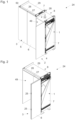
- the Figure 1 shows a piece of furniture 24 with a movable furniture part 4, which includes exactly one door leaf 4, and a movable furniture part 3, which includes two hingedly connected door leaves 5, 6.
- a movable furniture part 4 which includes exactly one door leaf 4
- a movable furniture part 3 which includes two hingedly connected door leaves 5, 6.
- an interior space 49 can be covered, in which, for example, kitchen appliances and/or kitchen furniture can be arranged. In this way, a hidden kitchen can be realized.
- the furniture 24 comprises cavities 28 which extend in a depth direction 22 of the furniture 24 and are preferably shaft-shaped, in which the movable furniture parts 3, 4 can be arranged.
- a guide arrangement 1 arranged on a furniture wall 7 of a fixed furniture part 8 is mounted.
- the Figure 2 shows a piece of furniture 24 with a movable furniture part 3, which includes two door leaves 5, 6 that are articulated to one another.
- the door leaves 5, 6 are articulated to one another via door hinges 25.
- a transverse guide rail 26 is arranged on an upper floor 29 of the furniture 24, with one of the two door leaves 5, 6 of the movable furniture part 3 being slidably mounted on the transverse guide rail 26 via a carriage 50 (see also Figure 1 ).
- the transverse guide rail 26 is partially covered with a cover element 27.
- furniture 24 is also conceivable which has only one movable furniture part 4, which includes exactly one door leaf 4, or furniture 24 with more than one movable furniture part 3 and / or more than one movable furniture part 4.
- a preferred exemplary embodiment of this method for mounting a guide arrangement 1 for a movable furniture part 3, which comprises at least two hingedly connected door leaves 5, 6, on a furniture wall 7 of a fixed furniture part 8 is described below.
- a preferred exemplary embodiment of the method for assembling a guide arrangement 1 for a movable furniture part 2, which includes exactly one door leaf 4, is then described on a furniture wall 7 of a fixed furniture part 8.
- the Figure 3 shows a furniture wall 3 of a fixed furniture part 8 of a piece of furniture 24, with one on the furniture wall 3 Guide arrangement for a movable furniture part 3, which comprises at least two hingedly connected door leaves 5, 6, is to be assembled. Holes 30 are arranged in the furniture wall 3. In addition, the furniture wall 3 has a recess 51.
- the Figure 4 shows the furniture wall 3 according to Figure 3 , wherein a first guide rail 9 and a third guide rail 16 are arranged on the furniture wall 3.
- the third guide rail 16 is arranged at a distance 15 from the first guide rail 9.
- the first guide rail 9 has an adjusting device 31, with which a second guide rail 13 (compare the Figure 5 ) is adjustable in the depth direction 22 of the furniture wall 7.
- the Figure 5 shows the furniture wall 3 according to Figure 4 additionally with a second guide rail 13, the second guide rail 13 being arranged on the long side 12 of the first guide rail 9 on the furniture wall 7.
- the first guide rail 9 and the second guide rail 13 are positively and slidably connected to one another (see also Figure 6b )).
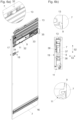
- FIGS. 6a) and 6b ) show the furniture wall 3 according to Figure 5 additionally with a drive device 11 and a damping device 18, in which Figure 6b ) additionally one on the first guide rail 9 and the second Guide rail 16 slidably mounted carrier 19 is shown.
- the drive device 11 for influencing the movement of the movable furniture part 3 is on a long side 10 (compare the Figure 5 ) of the first guide rail 9 arranged, the first guide rail 9 and the drive device 11 being positively connected to one another (compare the Figure 6b )).
- the drive device 11 can be designed in such a way that it accelerates, brakes and/or moves the movable furniture part 3 uniformly.
- the movement can be influenced over the entire distance between an arrangement of the movable furniture part 3 outside a cavity 28 formed with the furniture wall 7 (compare the Figure 1 ) and an arrangement of the movable furniture part 3 in an end position within the cavity 28 formed with the furniture wall 7.
- the movement can only be influenced in one or more sections of this route.
- the drive device 11 comprises an ejection device 33 for ejecting the movable furniture part 3 from an end position of the movable furniture part 3 relative to the furniture wall 7. Furthermore, a cable pull 34 is provided, with which the movable furniture part 3 is moved along the first guide rail 9 from a first End position can be moved into a second end position. The force exerted by the ejector 33 and the cable pull 34 overlap in such a way that the movable furniture part 3 can be moved from the first end position to the second end position without any force support from a user. When moving in the opposite direction, the ejector 33 and the cable pull 34 are reloaded.
- a holder 35 is arranged in an end region of the drive device 11. The function of this holder 35 is related to the Figure 8 described.
- the damping device 18 for damping a movement of the movable furniture part 3 is arranged on the furniture wall 7 at a distance 17 from the first guide rail 9.
- the damping device 18 is arranged on the furniture wall 7 in such a way that a movement of the movable furniture part 3 into an end position relative to the first guide rail 9 can be dampened.
- the second guide rail 13 is on the one hand positively connected to the first guide rail 9 and on the other hand attached to the furniture wall 7 via holding elements 32.
- the fastenings enable the second guide rail 13 to be displaced relative to the first guide rail 9 by means of the adjusting device 31 (compare the Figure 4 ).
- the drive device 11 can be attached on the one hand to the first guide rail 9 and on the other hand via holding elements 32 to the furniture wall 7, although a relative one Displaceability of the drive device 11 and the first guide rail 9 is not provided.
- the carrier 19 is connected to the first guide rail 9 via a guide device 36.
- the guide device 36 comprises support rollers 37, via which the weight of the carrier 19 and the movable furniture part 3 connected or connectable to it can be supported in the vertical direction 52, and support rollers 38, with which the carrier 19 can be supported in the horizontal direction 53.
- the Figure 7 shows the furniture wall 7 according to Figure 6a ) additionally with a carrier 19.
- the carrier 19 for the articulated mounting of the movable furniture part 3 is slidably mounted on the guide rails 9, 13, 16 provided.
- a compensation device 20 is arranged on the carrier 19 for compensating a tilting moment 21 of the at least one carrier 19 or the movable furniture part 3 arranged thereon about a tilting axis by a restoring moment 23.
- the compensation device 20 is connected to the drive device 11, specifically to the holder 35 of the drive device 11.
- the compensation device 20 comprises one
- the movable furniture part 2, 3 comprises exactly one door leaf 4 or at least two hingedly connected door leaves 5, 6, it is the same first guide rail 9, the same drive device 11, the same damping device 18 and the same carrier 19.
- a difference between the two exemplary embodiments is that in a further method step on the second longitudinal side 12 of the first guide rail 9 (instead of the second guide rail 13) there is at least one holding device 14 for holding the movable furniture part 2 in an end position relative to the first guide rail 9 on the furniture wall 7 is arranged, preferably wherein the first guide rail 9 and the at least one holding device 14 are connected to one another, particularly preferably in a form-fitting and / or displaceable manner.
- the holding device 14 can also be adjustable via an adjusting device 31 in the depth direction 22 of the furniture wall 7 relative to the first guide rail 9.
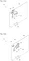
- FIG. 14a) A preferred embodiment is in the Figures 14a) and 14b ) shown, where the Figure 14a ) a stopping position and the Figure 14b ) show a release position.
- the holding device 14 comprises a pivoting lever mechanism 42 with a pivoting lever 44 which is rotatably mounted on a base body 48 about an axis of rotation 47.
- the pivoting lever 44 is inserted into the two via a spring device 43 Figures 14a) and 14b ) pushed to the end positions shown. A dead center position is formed between these positions.
- a stop 41 is provided, on which the pivot lever 44 is in the end position Figure 14a ).
- the pivoting lever 44 has a receptacle 45 into which a bolt or the like, which is connected or can be connected in a movement-coupled manner to the movable furniture part 2, can be inserted.
- a bolt or the like which is connected or can be connected in a movement-coupled manner to the movable furniture part 2
- the bolt and thus the movable furniture part 2 are held by the spring-loaded pivot lever 44. If a user wants to move the movable furniture part 2 out of this end position, he must overcome the spring force of the spring device 43.
- the pivot lever 44 is moved beyond the dead center position and into the end position Figure 14b ) emotional.
- the bolt and thus the movable furniture part 2 are released.
- a coupling element 46 is provided on the base body 48, which is or can be brought into engagement with the adjusting device 31, whereby the base body 48 and thus the entire holding device 14 can be displaced relative to the first guide rail 9.
- the compensation device 20 arranged on the carrier 19 is the same as in the Figures 3 to 8 preferred embodiment still based on the Figure 13 is connected to the furniture wall 7 or the drive device 11 (analogous to Figure 8 ).
- the method for assembling a guide arrangement 1 can be embedded in a method for assembling a piece of furniture 24, with which, for example, the in the Figures 1 or 2 Furniture 24 shown can be assembled.
- the movable furniture part 3 comprises at least two door leaves 5, 6 that are articulated to one another
- the at least two door leaves 5, 6 are connected to one another in an articulated manner via at least two door hinges 25 (compare Figure 2 ).
- the movable furniture part 3 comprises at least two hinged door leaves 5, 6, in a further method step at least one transverse guide rail 26 is arranged transversely to the first guide rail 9 on at least one fixed furniture part 8 and one of the at least two Door leaves 5, 6 of the movable furniture part 3 are connected to the at least one transverse guide rail 26 via at least one carriage 50 (compare the Figure 2 ).
- the at least one transverse guide rail 26 is covered at least partially with at least one cover element 27 in a further method step.
Landscapes
- Engineering & Computer Science (AREA)
- Mechanical Engineering (AREA)
- Hinges (AREA)
- Support Devices For Sliding Doors (AREA)
- Power-Operated Mechanisms For Wings (AREA)
- Cabinets, Racks, Or The Like Of Rigid Construction (AREA)
- Telephone Set Structure (AREA)
- Supports Or Holders For Household Use (AREA)
Abstract
- es wird eine erste Führungsschiene (9) zur Führung des bewegbaren Möbelteils (2, 3) an der Möbelwand (7) angeordnet,
- es wird an einer ersten Längsseite (10) der ersten Führungsschiene (9) wenigstens eine Antriebsvorrichtung (11) zur Bewegungsbeeinflussung des bewegbaren Möbelteils (2, 3) an der Möbelwand (7) angeordnet, bevorzugt wobei die erste Führungsschiene (9) und die wenigstens eine Antriebsvorrichtung (11), besonders bevorzugt formschlüssig, miteinander verbunden sind, und
- für den Fall, dass das bewegbare Möbelteil (3) wenigstens zwei gelenkig miteinander verbundene Türflügel (5, 6) umfasst, wird an einer zweiten Längsseite (12) der ersten Führungsschiene (9) eine zweite Führungsschiene (13) zur Führung des bewegbaren Möbelteils (3) an der Möbelwand (7) angeordnet, bevorzugt wobei die erste Führungsschiene (9) und die zweite Führungsschiene (13), besonders bevorzugt formschlüssig und/oder verschiebbar, miteinander verbunden sind.
Description
- Die Erfindung betrifft ein Verfahren zur Montage einer Führungsanordnung für ein bewegbares Möbelteil, welches entweder genau einen Türflügel oder wenigstens zwei gelenkig miteinander verbundene Türflügel umfasst, an einer Möbelwand eines feststehenden Möbelteils. Die Erfindung betrifft weiterhin ein Verfahren zur Montage eines Möbels, bei dem das Verfahren zur Montage einer Führungsanordnung zum Einsatz kommt.
- Aus dem Stand der Technik sind bereits Verfahren gemäß dem Oberbegriff des Anspruchs 1 bekannt. Dabei kommen unterschiedliche Führungsanordnungen zum Einsatz, je nachdem, ob das mittels der Führungsanordnung zu führende bewegbare Möbelteil genau einen Türflügel oder wenigstens zwei gelenkig miteinander verbundene Türflügel umfasst.
- Nachteilig dabei ist, dass der Monteur beide Versionen der Führungsanordnung vorrätig halten muss, wenn er nicht nur Führungsanordnungen einer Art des zu führenden bewegbaren Möbelteils verarbeitet. Weiterhin ist die Herstellung der Führungsanordnungen mit hohen Kosten verbunden, da die Führungsanordnungen unterschiedlich ausgebildet sind und daher zwei Fertigungsstraßen benötigt werden.
- Die Aufgabe der vorliegenden Erfindung besteht darin, diese Nachteile zumindest teilweise zu vermeiden und ein gegenüber dem Stand der Technik verbessertes Verfahren zur Montage einer Führungsanordnung für ein bewegbares Möbelteil, welches entweder genau einen Türflügel oder wenigstens zwei gelenkig miteinander verbundene Türflügel umfasst, an einer Möbelwand eines feststehenden Möbelteils anzugeben, welches einem Monteur insbesondere eine höhere Flexibilität bei der Herstellung von Möbeln gestattet und auf Seiten des Herstellers mit geringeren Herstellungskosten verbunden ist. Weiterhin soll ein Verfahren zur Montage eines Möbels, bei dem das verbesserte Verfahren zur Montage einer Führungsanordnung zum Einsatz kommt, angegeben werden.
- Diese Aufgaben werden gelöst durch die Merkmale der Ansprüche 1 und 8.
- Beim erfindungsgemäßen Verfahren zur Montage einer Führungsanordnung für ein bewegbares Möbelteil, welches entweder genau einen Türflügel oder wenigstens zwei gelenkig miteinander verbundene Türflügel umfasst, an einer Möbelwand eines feststehenden Möbelteils sind demnach die, vorzugsweise in der angegebenen Reihenfolge chronologischen, Verfahrensschritte vorgesehen:
- es wird eine erste Führungsschiene zur Führung des bewegbaren Möbelteils an der Möbelwand angeordnet,
- es wird an einer ersten Längsseite der ersten Führungsschiene wenigstens eine Antriebsvorrichtung zur Bewegungsbeeinflussung des bewegbaren Möbelteils an der Möbelwand angeordnet, bevorzugt wobei die erste Führungsschiene und die wenigstens eine Antriebsvorrichtung, besonders bevorzugt formschlüssig, miteinander verbunden sind, und
- für den Fall, dass das bewegbare Möbelteil wenigstens zwei gelenkig miteinander verbundene Türflügel umfasst, wird an einer zweiten Längsseite der ersten Führungsschiene eine zweite Führungsschiene zur Führung des bewegbaren Möbelteils an der Möbelwand angeordnet, bevorzugt wobei die erste Führungsschiene und die zweite Führungsschiene, besonders bevorzugt formschlüssig und/oder verschiebbar, miteinander verbunden sind.
- Dadurch ist es möglich, die Führungsanordnung aus einer Art Baukasten zusammen zu stellen, wobei möglichst viele Gleichteile eingesetzt werden, die sowohl bei einer Führungsanordnung für ein bewegbares Möbelteil, welches genau einen Türflügel umfasst, als auch bei einer Führungsanordnung für ein bewegbares Möbelteil, welches wenigstens zwei gelenkig miteinander verbundene Türflügel umfasst, zur Anwendung kommen.
- Die Gleichteile können in größerer Stückzahl und in derselben Fertigungsstraße gefertigt werden, wodurch die Kosten in der Herstellung der Führungsanordnung sinken.
- Gemäß einer bevorzugten Ausführungsform des Verfahrens ist es vorgesehen, dass es sich, unabhängig davon, ob das bewegbare Möbelteil genau einen Türflügel oder wenigstens zwei gelenkig miteinander verbundene Türflügel umfasst, um dieselbe erste Führungsschiene und/oder dieselbe Antriebsvorrichtung handelt. Dadurch kann die Anzahl der Gleichteile erhöht werden.
- Als vorteilhaft hat es sich erwiesen, dass für den Fall, dass das bewegbare Möbelteil genau einen Türflügel umfasst, in einem weiteren Verfahrensschritt an der zweiten Längsseite der ersten Führungsschiene wenigstens eine Haltevorrichtung zum Halten des bewegbaren Möbelteils in einer Endlage relativ zur ersten Führungsschiene an der Möbelwand angeordnet wird, bevorzugt wobei die erste Führungsschiene und die wenigstens eine Haltevorrichtung, besonders bevorzugt formschlüssig und/oder verschiebbar, miteinander verbunden sind. Dadurch ist es möglich, das bewegbare Möbelteil mittels der Führungsanordnung in eine definierte Endlage relativ zur ersten Führungsschiene zu bewegen, wodurch die Gefahr einer Beschädigung, welche durch eine Fehlbedienung des Möbelteils ausgeht, verringert wird.
- Alternativ oder ergänzend kann es vorgesehen sein, dass in einem weiteren Verfahrensschritt in einem Abstand zur ersten Führungsschiene eine dritte Führungsschiene zur Führung des bewegbaren Möbelteils an der Möbelwand angeordnet wird, vorzugsweise wobei es sich, unabhängig davon, ob das bewegbare Möbelteil genau einen Türflügel oder wenigstens zwei gelenkig miteinander verbundene Türflügel umfasst, um dieselbe dritte Führungsschiene handelt. Dadurch kann das bewegbare Möbelteil mittels der Führungsanordnung besonders stabil an der Möbelwand geführt werden.
- Eine besonders harmonische Bewegung des mittels der Führungsanordnung zu führenden bewegbaren Möbelteils lässt sich dadurch realisieren, dass in einem weiteren Verfahrensschritt in einem Abstand zur ersten Führungsschiene wenigstens eine Dämpfungsvorrichtung zur Dämpfung einer Bewegung des bewegbaren Möbelteils, vorzugsweise in eine Endlage relativ zur ersten Führungsschiene, an der Möbelwand angeordnet wird, vorzugsweise wobei es sich, unabhängig davon, ob das bewegbare Möbelteil genau einen Türflügel oder wenigstens zwei gelenkig miteinander verbundene Türflügel umfasst, um dieselbe Dämpfungsvorrichtung handelt.
- An bietet sich in günstiger Weise an, dass in einem weiteren Verfahrensschritt wenigstens ein Träger zur gelenkigen Lagerung des bewegbaren Möbelteils an den vorgesehenen Führungsschienen verschiebbar gelagert wird, vorzugsweise wobei es sich, unabhängig davon, ob das bewegbare Möbelteil genau einen Türflügel oder wenigstens zwei gelenkig miteinander verbundene Türflügel umfasst, um denselben Träger handelt. Dadurch wird die Montage erleichtert, da der Träger zunächst an den vorgesehen Führungsschienen montiert werden kann und anschließend das bewegbare Möbelteil nur noch mit dem Träger verbunden werden muss.
- In diesem Zusammenhang hat es sich als vorteilhaft erwiesen, dass am wenigstens einen Träger wenigstens eine Kompensationsvorrichtung zur Kompensation eines Kippmoments des wenigstens einen Trägers oder des daran angeordneten bewegbaren Möbelteils um eine Kippachse durch ein Rückstellmoment angeordnet ist und in einem weiteren Verfahrensschritt die wenigstens eine Kompensationsvorrichtung mit der Möbelwand, vorzugsweise mit der an der Möbelwand angeordneten wenigstens einen Antriebsvorrichtung, verbunden wird. Dadurch kann die Gefahr eines Verkantens des mittels der Führungsanordnung zu führenden bewegbaren Möbelteils reduziert werden.
- Schutz wird auch begehrt für ein Verfahren zur Montage eines Möbels mit wenigstens einem feststehenden Möbelteil, wenigstens einem bewegbaren Möbelteil, welches entweder genau einen Türflügel oder wenigstens zwei gelenkig miteinander verbundene Türflügel umfasst, und wenigstens einer Führungsanordnung für das bewegbare Möbelteil, wobei zunächst die wenigstens eine Führungsanordnung gemäß dem erfindungsgemäßen Verfahren an einer Möbelwand des wenigstens einen feststehenden Möbelteils durchgeführt wird und anschließend das bewegbare Möbelteil zumindest an der ersten Führungsschiene verschiebbar gelagert wird, vorzugsweise indirekt über wenigstens einen Träger.
- In einer vorteilhaften Ausführungsform ist es vorgesehen, dass für den Fall, dass das bewegbare Möbelteil wenigstens zwei gelenkig miteinander verbundene Türflügel umfasst, in einem weiteren Verfahrensschritt die wenigstens zwei Türflügel über wenigstens zwei Türscharniere gelenkig miteinander verbunden werden.
- Alternativ oder ergänzend kann es vorgesehen sein, dass für den Fall, dass das bewegbare Möbelteil wenigstens zwei gelenkig miteinander verbundene Türflügel umfasst, in einem weiteren Verfahrensschritt wenigstens eine Querführungsschiene quer zur ersten Führungsschiene am wenigstens einen feststehenden Möbelteil angeordnet und einer der wenigstens zwei Türflügel des bewegbaren Möbelteils über wenigstens einen Laufwagen mit der wenigstens einen Querführungsschiene verbunden wird. Dadurch kann das bewegbare Möbelteil mittels der Führungsanordnung in jeder Stellung sicher geführt werden.
- In diesem Zusammenhang hat es sich als vorteilhaft erwiesen, dass die wenigstens eine Querführungsschiene in einem weiteren Verfahrensschritt zumindest bereichsweise mit wenigstens einem Blendenelement abgedeckt wird. Dadurch kann eine ästhetisch vorteilhafte Erscheinungsform des zu montierenden Möbels erzielt werden.
- Weitere Einzelheiten und Vorteile der Erfindung werden anhand der Figurenbeschreibung unter Bezugnahme auf die Zeichnungen im Folgenden näher erläutert. Darin zeigen:
- Fig. 1
- ein Möbel mit einem bewegbaren Möbelteil, welches genau einen Türflügel umfasst, und einem bewegbaren Möbelteil, welches zwei gelenkig miteinander verbundene Türflügel umfasst, in einer schematisch dargestellten perspektivischen Ansicht,
- Fig. 2
- ein Möbel mit einem bewegbaren Möbelteil, welches zwei gelenkig miteinander verbundene Türflügel umfasst, in einer schematisch dargestellten perspektivischen Ansicht,
- Fig. 3
- eine Möbelwand eines feststehenden Möbelteils eines Möbels mit einem bewegbaren Möbelteil, welches wenigstens zwei gelenkig miteinander verbundene Türflügel umfasst, in einer schematisch dargestellten perspektivischen Ansicht,
- Fig. 4
- die Möbelwand gemäß
Figur 3 mit einer ersten und einer dritten Führungsschiene, - Fig. 5
- die Möbelwand gemäß
Figur 4 zusätzlich mit einer zweiten Führungsschiene, - Fig. 6a), b)
- die Möbelwand gemäß
Figur 5 zusätzlich mit einer Antriebsvorrichtung und einer Dämpfungsvorrichtung, wobei die Teilfigur a) eine schematisch dargestellten perspektivischen Ansicht und die Teilfigur b) eine schematisch dargestellte Seitenansicht von hinten zeigen, wobei in der Teilfigur b) zusätzlich ein an der ersten und zweite Führungsschiene verschiebbar gelagerter Träger dargestellt ist, - Fig. 7
- die Möbelwand gemäß
Figur 6a ) zusätzlich mit einem Träger, - Fig. 8
- die Möbelwand gemäß
Figur 7 , wobei eine am Träger angeordnete Kompensationsvorrichtung mit der Antriebsvorrichtung verbunden ist, - Fig. 9
- eine Möbelwand eines feststehenden Möbelteils eines Möbels mit einem bewegbaren Möbelteil, welches genau einen Türflügel umfasst, in einer schematisch dargestellten perspektivischen Ansicht,
- Fig. 10
- die Möbelwand gemäß
Figur 9 mit einer ersten Führungsschiene, - Fig. 11a),
- b) die Möbelwand gemäß
Figur 10 zusätzlich mit einer Antriebsvorrichtung, wobei die Teilfigur a) eine schematisch dargestellten perspektivischen Ansicht und die Teilfigur b) eine schematisch dargestellte Seitenansicht von hinten zeigen, - Fig. 12a)
- die Möbelwand gemäß
Figur 11a ) zusätzlich mit einer Dämpfungsvorrichtung, einer dritten Führungsschiene und einer Haltevorrichtung, - Fig. 12b)
- die vergrößerte Ansicht aus
Figur 11b ), wobei die Antriebsvorrichtung über ein Halteelement an der Möbelwand befestigt ist, - Fig. 13
- die Möbelwand gemäß
Figur 12a ) zusätzlich mit einem Träger, und - Fig. 14a), b)
- eine Haltevorrichtung zum Halten eines bewegbaren Möbelteils, welches genau einen Türflügel umfasst, wobei die Teilfigur a) eine Haltestellung und die Teilfigur b) eine Lösestellung zeigen, jeweils in einer schematisch dargestellten perspektivischen Ansicht.
- Die
Figur 1 zeigt ein Möbel 24 mit einem bewegbaren Möbelteil 4, welches genau einen Türflügel 4 umfasst, und einem bewegbaren Möbelteil 3, welches zwei gelenkig miteinander verbundene Türflügel 5, 6 umfasst. Mit den bewegbaren Möbelteilen 3, 4 ist jeweils ein Innenraum 49 abdeckbar, in welchem beispielsweise Küchengeräte und/oder Küchenmöbel anordenbar sind. Auf diese Weise kann eine versteckbare Küche realisiert werden. - Anders als in der
Figur 1 dargestellt, kann es sich auch um einen gemeinsamen Innenraum 49 handeln, welche von einer ersten Seite von dem bewegbaren Möbelteil 3 und von einer zweiten Seite von dem bewegbaren Möbelteil 4 abdeckbar ist. - Das Möbel 24 umfasst sich in eine Tiefenrichtung 22 des Möbels 24 erstreckende, vorzugsweise schachtförmig ausgebildete, Hohlräume 28, in denen die bewegbaren Möbelteile 3, 4 anordenbar sind.
- Zur Führung der bewegbaren Möbelteile 3, 4 in den Hohlräumen 28 ist jeweils eine an einer Möbelwand 7 eines feststehenden Möbelteils 8 angeordnete Führungsanordnung 1 montiert.
- Die
Figur 2 zeigt ein Möbel 24 mit einem bewegbaren Möbelteil 3, welches zwei gelenkig miteinander verbundene Türflügel 5, 6 umfasst. Die Türflügel 5, 6 sind über Türscharniere 25 gelenkig miteinander verbunden. - An einem Oberboden 29 des Möbels 24 ist eine Querführungsschiene 26 angeordnet, wobei einer der zwei Türflügel 5, 6 des bewegbaren Möbelteils 3 über einen Laufwagen 50 an der Querführungsschiene 26 verschiebbar gelagert ist (vergleiche auch
Figur 1 ). Die Querführungsschiene 26 ist bereichsweise mit einem Blendenelement 27 abgedeckt. - Neben den in den
Figuren 1 und 2 dargestellten Möbeln 24, sind auch Möbel 24 denkbar, welche nur ein bewegbares Möbelteil 4, welches genau einen Türflügel 4 umfasst, aufweist, oder Möbel 24 mit mehr als einem bewegbaren Möbelteil 3 und/oder mehr als einem bewegbaren Möbelteil 4. - Bei der gegenständlichen Erfindung geht es gemäß einem ersten Aspekt um ein Verfahren zur Montage einer Führungsanordnung 1 für ein bewegbares Möbelteil 2, 3, welches entweder genau einen Türflügel 4 oder wenigstens zwei gelenkig miteinander verbundene Türflügel 5, 6 umfasst, an einer Möbelwand 7 eines feststehenden Möbelteils 8, umfassend die, vorzugsweise in der angegebenen Reihenfolge chronologischen, Verfahrensschritte:
- es wird eine erste Führungsschiene 9 zur Führung des bewegbaren Möbelteils 2, 3 an der Möbelwand 7 angeordnet,
- es wird an einer ersten Längsseite 10 der ersten Führungsschiene 9 wenigstens eine Antriebsvorrichtung 11 zur Bewegungsbeeinflussung des bewegbaren Möbelteils 2, 3 an der Möbelwand 7 angeordnet, bevorzugt wobei die erste Führungsschiene 9 und die wenigstens eine Antriebsvorrichtung 11, besonders bevorzugt formschlüssig, miteinander verbunden sind, und
- für den Fall, dass das bewegbare Möbelteil 3 wenigstens zwei gelenkig miteinander verbundene Türflügel 5, 6 umfasst, wird an einer zweiten Längsseite 12 der ersten Führungsschiene 9 eine zweite Führungsschiene 13 zur Führung des bewegbaren Möbelteils 3 an der Möbelwand 7 angeordnet, bevorzugt wobei die erste Führungsschiene 9 und die zweite Führungsschiene 13, besonders bevorzugt formschlüssig und/oder verschiebbar, miteinander verbunden sind.
- Anhand der
Figuren 3 bis 8 wird im Folgenden ein bevorzugtes Ausführungsbeispiel dieses Verfahrens zur Montage einer Führungsanordnung 1 für ein bewegbares Möbelteil 3, welches wenigstens zwei gelenkig miteinander verbundene Türflügel 5, 6 umfasst, an einer Möbelwand 7 eines feststehenden Möbelteils 8 beschrieben. Anhand derFiguren 9 bis 14b ) wird anschließend ein bevorzugtes Ausführungsbeispiel des Verfahrens zur Montage einer Führungsanordnung 1 für ein bewegbares Möbelteil 2, welches genau einen Türflügel 4 umfasst, an einer Möbelwand 7 eines feststehenden Möbelteils 8 beschrieben. - Die
Figur 3 zeigt eine Möbelwand 3 eines feststehenden Möbelteils 8 eines Möbels 24, wobei an der Möbelwand 3 eine Führungsanordnung für ein bewegbares Möbelteil 3, welches wenigstens zwei gelenkig miteinander verbundene Türflügel 5, 6 umfasst, montiert werden soll. In der Möbelwand 3 sind Bohrungen 30 angeordnet. Außerdem weist die Möbelwand 3 eine Aussparung 51 auf. - Die
Figur 4 zeigt die Möbelwand 3 gemäßFigur 3 , wobei eine ersten Führungsschiene 9 und einer dritten Führungsschiene 16 an der Möbelwand 3 angeordnet sind. - Die dritte Führungsschiene 16 ist in einem Abstand 15 zur ersten Führungsschiene 9 angeordnet.
- Die erste Führungsschiene 9 weist eine Verstellvorrichtung 31 auf, mit welcher eine an einer Längsseite 12 der ersten Führungsschiene 9 angeordnete zweite Führungsschiene 13 (vergleiche die
Figur 5 ) in Tiefenrichtung 22 der Möbelwand 7 verstellbar ist. - Die
Figur 5 zeigt die Möbelwand 3 gemäßFigur 4 zusätzlich mit einer zweiten Führungsschiene 13, wobei die zweite Führungsschiene 13 an der Längsseite 12 der ersten Führungsschiene 9 an der Möbelwand 7 angeordnet ist. - Die erste Führungsschiene 9 und die zweite Führungsschiene 13 sind formschlüssig und verschiebbar miteinander verbunden (vergleiche auch die
Figur 6b )). - Die
Figuren 6a) und 6b ) zeigen die Möbelwand 3 gemäßFigur 5 zusätzlich mit einer Antriebsvorrichtung 11 und einer Dämpfungsvorrichtung 18, wobei in derFigur 6b ) zusätzlich ein an der ersten Führungsschiene 9 und der zweite Führungsschiene 16 verschiebbar gelagerter Träger 19 dargestellt ist. - Die Antriebsvorrichtung 11 zur Bewegungsbeeinflussung des bewegbaren Möbelteils 3 ist an einer Längsseite 10 (vergleiche die
Figur 5 ) der ersten Führungsschiene 9 angeordnet, wobei die erste Führungsschiene 9 und die Antriebsvorrichtung 11 formschlüssig miteinander verbunden sind (vergleiche dieFigur 6b )). - Es sind unterschiedliche Ausführungsformen der Antriebsvorrichtung 11 möglich. Die Antriebsvorrichtung 11 kann derart ausgebildet sein, dass sie das bewegbare Möbelteil 3 beschleunigt, abbremst und/oder gleichförmig bewegt. Dabei kann die Bewegungsbeeinflussung auf der gesamten Wegstrecke zwischen einer Anordnung des bewegbaren Möbelteils 3 außerhalb eines mit der Möbelwand 7 ausgebildeten Hohlraums 28 (vergleiche die
Figur 1 ) und einer Anordnung des bewegbaren Möbelteils 3 in einer Endstellung innerhalb des mit der Möbelwand 7 ausgebildeten Hohlraums 28 erfolgen. Alternativ kann die Bewegungsbeeinflussung nur einem oder mehreren Teilabschnitten dieser Wegstrecke erfolgen. - Im konkret dargestellten Fall umfasst die Antriebsvorrichtung 11 eine Ausstoßvorrichtung 33 zum Ausstoßen des bewegbaren Möbelteils 3 aus einer Endlage des bewegbaren Möbelteils 3 relativ zur Möbelwand 7. Weiterhin ist ein Seilzug 34 vorgesehen, mit welchem das bewegbare Möbelteil 3 entlang der ersten Führungsschiene 9 aus einer ersten Endlage in eine zweite Endlage bewegbar ist. Die Krafteinwirkung der Ausstoßvorrichtung 33 und des Seilzugs 34 überlagern sich derart, dass das bewegbare Möbelteil 3 ohne Kraftunterstützung eines Nutzers aus der ersten Endlage in die zweite Endlage bewegbar ist. Bei einer Bewegung in die umgekehrte Richtung werden die Ausstoßvorrichtung 33 und der Seilzug 34 wieder geladen.
- In einem endseitigen Bereich der Antriebsvorrichtung 11 ist ein Halter 35 angeordnet. Die Funktion dieses Halters 35 wird in Zusammenhang mit der
Figur 8 beschrieben. - Die Dämpfungsvorrichtung 18 zur Dämpfung einer Bewegung des bewegbaren Möbelteils 3 ist in einem Abstand 17 zur ersten Führungsschiene 9 an der Möbelwand 7 angeordnet.
- Im konkret dargestellten Fall die die Dämpfungsvorrichtung 18 derart an der Möbelwand 7 angeordnet, dass eine Bewegung des bewegbaren Möbelteils 3 in eine Endlage relativ zur ersten Führungsschiene 9 dämpfbar ist.
- Wie aus dem vergrößerten Ausschnitte der
Figur 6a ) hervorgeht, ist die zweite Führungsschiene 13 einerseits formschlüssig mit der ersten Führungsschiene 9 und andererseits über Halteelemente 32 an der Möbelwand 7 befestigt. Die Befestigungen ermöglichen eine Verschiebung der zweiten Führungsschiene 13 relativ zur ersten Führungsschiene 9 mittels der Verstellvorrichtung 31 (vergleiche dieFigur 4 ). - In analoger Weise kann die Befestigung der Antriebsvorrichtung 11 einerseits an der ersten Führungsschiene 9 und andererseits über Halteelemente 32 an der Möbelwand 7 erfolgen, wobei allerdings eine relative Verschiebbarkeit der Antriebsvorrichtung 11 und der ersten Führungsschiene 9 nicht vorgesehen ist.
- Wie aus der
Figur 6b ) hervorgeht, ist der Träger 19 über eine Führungsvorrichtung 36 mit der ersten Führungsschiene 9 verbunden. Die Führungsvorrichtung 36 umfasst Tragrollen 37, über welches das Gewicht des Trägers 19 und des damit verbundenen oder verbindbaren beweglichen Möbelteils 3 in vertikaler Richtung 52 abstützbar ist, und Stützrollen 38, mit welcher der Träger 19 in horizontaler Richtung 53 abstützbar ist. - Die
Figur 7 zeigt die Möbelwand 7 gemäßFigur 6a ) zusätzlich mit einem Träger 19. - Der Träger 19 zur gelenkigen Lagerung des bewegbaren Möbelteils 3 ist an den vorgesehenen Führungsschienen 9, 13, 16 verschiebbar gelagert. Am Träger 19 ist eine Kompensationsvorrichtung 20 zur Kompensation eines Kippmoments 21 des wenigstens einen Trägers 19 oder des daran angeordneten bewegbaren Möbelteils 3 um eine Kippachse durch ein Rückstellmoment 23 angeordnet.
- In der
Figur 8 ist die Kompensationsvorrichtung 20 mit der Antriebsvorrichtung 11 verbunden, konkret mit dem Halter 35 der Antriebsvorrichtung 11. - Es sind unterschiedliche Ausführungsformen der Kompensationsvorrichtung 20 möglich. Im konkret dargestellten Fall umfasst die Kompensationsvorrichtung 20 eine
- Y-förmig ausgebildete Scherenmechanik 39 und eine Seilvorrichtung 40 mit einem Z-förmig verlaufenden Zugseil.
- Die zeitliche Reihenfolge bei der Montage der Führungsanordnung 1 an der Möbelwand 7 kann wie folgt festgelegt sein:
- 1. die Möbelwand 7 wird bereitgestellt
- 2. die erste Führungsschiene 9 wird an der Möbelwand 7 angeordnet
- 3. die dritte Führungsschiene 16 wird an der Möbelwand 7 angeordnet
- 4. die zweite Führungsschiene 13 wird an der Möbelwand 7 angeordnet
- 5. die Antriebsvorrichtung 11 wird an der Möbelwand 7 angeordnet
- 6. die Dämpfungsvorrichtung 18 wird an der Möbelwand 7 angeordnet
- 7. der Träger 19 wird an den Führungsschienen 9, 16, 13 verschiebbar gelagert
- 8. die Kompensationsvorrichtung 20 wird mit der Möbelwand 7 und/oder der Antriebsvorrichtung 11 verbunden.
- Das anhand der
Figuren 9 bis 14b ) veranschaulichte bevorzugte Ausführungsbeispiel des Verfahrens zur Montage einer Führungsanordnung 1 für ein bewegbares Möbelteil 2, welches genau einen Türflügel 4 umfasst, läuft im Wesentlichen analog zu dem in denFiguren 3 bis 8 dargestellten bevorzugten Ausführungsbeispiel des Verfahrens zur Montage einer Führungsanordnung 1 für ein bewegbares Möbelteil 3, welches wenigstens zwei gelenkig miteinander verbundene Türflügel 5, 6 umfasst, ab. - Wie ein Vergleich zeigt, können dabei Gleichteile eingesetzt werden. So handelt es sich, unabhängig davon, ob das bewegbare Möbelteil 2, 3 genau einen Türflügel 4 oder wenigstens zwei gelenkig miteinander verbundene Türflügel 5, 6 umfasst, um dieselbe erste Führungsschiene 9, dieselbe Antriebsvorrichtung 11, dieselbe Dämpfungsvorrichtung 18 und denselben Träger 19.
- Ein Unterschied der beiden Ausführungsbeispiele besteht darin, dass in einem weiteren Verfahrensschritt an der zweiten Längsseite 12 der ersten Führungsschiene 9 (anstelle der zweiten Führungsschiene 13) wenigstens eine Haltevorrichtung 14 zum Halten des bewegbaren Möbelteils 2 in einer Endlage relativ zur ersten Führungsschiene 9 an der Möbelwand 7 angeordnet wird, bevorzugt wobei die erste Führungsschiene 9 und die wenigstens eine Haltevorrichtung 14, besonders bevorzugt formschlüssig und/oder verschiebbar, miteinander verbunden sind.
- Die Haltevorrichtung 14 kann ebenfalls über eine Verstellvorrichtung 31 in Tiefenrichtung 22 der Möbelwand 7 relativ zur ersten Führungsschiene 9 verstellbar sein.
- Es sind unterschiedliche Ausführungsformen der Haltevorrichtung 14 möglich. Eine bevorzugte Ausführungsform ist in den
Figuren 14a) und 14b ) gezeigt, wobei dieFigur 14a ) eine Haltestellung und dieFigur 14b ) eine Lösestellung zeigen. - Die Haltevorrichtung 14 umfasst eine Schwenkhebelmechanik 42 mit einem um eine Drehachse 47 an einem Grundkörper 48 drehbar gelagerten Schwenkhebel 44. Der Schwenkhebel 44 wird über eine Federvorrichtung 43 in die beiden in den
Figuren 14a) und 14b ) gezeigten Endstellungen gedrängt. Zwischen diesen Stellungen ist eine Totpunktlage ausgebildet. Es ist ein Anschlag 41 vorgesehen, an welchem der Schwenkhebel 44 in der Endstellung gemäßFigur 14a ) anliegt. - Der Schwenkhebel 44 weist eine Aufnahme 45 auf, in welche ein Bolzen oder dergleichen, welcher mit dem bewegbaren Möbelteil 2 bewegungsgekoppelt verbunden oder verbindbar ist, einführbar ist. In der Endstellung gemäß
Figur 14a ) wird der Bolzen und damit das bewegbare Möbelteil 2 durch den federbelasteten Schwenkhebel 44 gehalten. Möchte ein Nutzer das bewegbare Möbelteil 2 aus dieser Endstellung bewegen, so muss er die Federkraft der Federvorrichtung 43 überwinden. Der Schwenkhebel 44 wird dabei über die Totpunktlage hinaus und in die Endstellung gemäßFigur 14b ) bewegt. Dabei werden der Bolzen und damit das bewegbare Möbelteil 2 freigegen. - Am Grundkörper 48 ist ein Koppelelement 46 vorgesehen, welches in Eingriff mit der Verstellvorrichtung 31 steht oder bringbar ist, wodurch der Grundkörper 48 und damit die gesamte Haltevorrichtung 14 relativ zur ersten Führungsschiene 9 verschiebbar ist.
- Es sei noch darauf hingewiesen, dass die am Träger 19 angeordnete Kompensationsvorrichtung 20 genauso wie beim in den
Figuren 3 bis 8 bevorzugten Ausführungsbeispiel noch ausgehend von derFigur 13 mit der Möbelwand 7 oder der Antriebsvorrichtung 11 verbunden wird (analog zurFigur 8 ). - Das Verfahren zur Montage einer Führungsanordnung 1 kann in ein Verfahren zur Montage eines Möbels 24 eingebettet werden, mit dem beispielsweise die in den
Figuren 1 oder 2 dargestellten Möbel 24 montierbar sind. - Konkret handelt es sich um ein Verfahren zur Montage eines Möbels 24 mit wenigstens einem feststehenden Möbelteil 8, wenigstens einem bewegbaren Möbelteil 2, 3, welches entweder genau einen Türflügel 4 oder wenigstens zwei gelenkig miteinander verbundene Türflügel 5, 6 umfasst, und wenigstens einer Führungsanordnung 1 für das bewegbare Möbelteil 2, 3, wobei zunächst die wenigstens eine Führungsanordnung 1 gemäß dem erfindungsgemäßen Verfahren an einer Möbelwand 7 des wenigstens einen feststehenden Möbelteils 8 durchgeführt wird und anschließend das bewegbare Möbelteil 2, 3 zumindest an der ersten Führungsschiene 9 verschiebbar gelagert wird, vorzugsweise indirekt über wenigstens einen Träger 19.
- Für den Fall, dass das bewegbare Möbelteil 3 wenigstens zwei gelenkig miteinander verbundene Türflügel 5, 6 umfasst, werden in einem weiteren Verfahrensschritt die wenigstens zwei Türflügel 5, 6 über wenigstens zwei Türscharniere 25 gelenkig miteinander verbunden (vergleiche die
Figur 2 ). - Für den Fall, dass das bewegbare Möbelteil 3 wenigstens zwei gelenkig miteinander verbundene Türflügel 5, 6 umfasst, wird in einem weiteren Verfahrensschritt wenigstens eine Querführungsschiene 26 quer zur ersten Führungsschiene 9 am wenigstens einen feststehenden Möbelteil 8 angeordnet und einer der wenigstens zwei Türflügel 5, 6 des bewegbaren Möbelteils 3 über wenigstens einen Laufwagen 50 mit der wenigstens einen Querführungsschiene 26 verbunden (vergleiche die
Figur 2 ). - Die wenigstens eine Querführungsschiene 26 wird in einem weiteren Verfahrensschritt zumindest bereichsweise mit wenigstens einem Blendenelement 27 abgedeckt.
Claims (11)
- Verfahren zur Montage einer Führungsanordnung (1) für ein bewegbares Möbelteil (2, 3), welches entweder genau einen Türflügel (4) oder wenigstens zwei gelenkig miteinander verbundene Türflügel (5, 6) umfasst, an einer Möbelwand (7) eines feststehenden Möbelteils (8), gekennzeichnet durch die, vorzugsweise in der angegebenen Reihenfolge chronologischen, Verfahrensschritte:- es wird eine erste Führungsschiene (9) zur Führung des bewegbaren Möbelteils (2, 3) an der Möbelwand (7) angeordnet,- es wird an einer ersten Längsseite (10) der ersten Führungsschiene (9) wenigstens eine Antriebsvorrichtung (11) zur Bewegungsbeeinflussung des bewegbaren Möbelteils (2, 3) an der Möbelwand (7) angeordnet, bevorzugt wobei die erste Führungsschiene (9) und die wenigstens eine Antriebsvorrichtung (11), besonders bevorzugt formschlüssig, miteinander verbunden sind, und- für den Fall, dass das bewegbare Möbelteil (3) wenigstens zwei gelenkig miteinander verbundene Türflügel (5, 6) umfasst, wird an einer zweiten Längsseite (12) der ersten Führungsschiene (9) eine zweite Führungsschiene (13) zur Führung des bewegbaren Möbelteils (3) an der Möbelwand (7) angeordnet, bevorzugt wobei die erste Führungsschiene (9) und die zweite Führungsschiene (13), besonders bevorzugt formschlüssig und/oder verschiebbar, miteinander verbunden sind.
- Verfahren nach Anspruch 1, wobei es sich, unabhängig davon, ob das bewegbare Möbelteil (2, 3) genau einen Türflügel (4) oder wenigstens zwei gelenkig miteinander verbundene Türflügel (5, 6) umfasst, um dieselbe erste Führungsschiene (9) und/oder dieselbe Antriebsvorrichtung (11) handelt.
- Verfahren nach Anspruch 1 oder 2, wobei für den Fall, dass das bewegbare Möbelteil (2) genau einen Türflügel (4) umfasst, in einem weiteren Verfahrensschritt an der zweiten Längsseite (12) der ersten Führungsschiene (9) wenigstens eine Haltevorrichtung (14) zum Halten des bewegbaren Möbelteils (2) in einer Endlage relativ zur ersten Führungsschiene (9) an der Möbelwand (7) angeordnet wird, bevorzugt wobei die erste Führungsschiene (9) und die wenigstens eine Haltevorrichtung (14), besonders bevorzugt formschlüssig und/oder verschiebbar, miteinander verbunden sind.
- Verfahren nach einem der Ansprüche 1 bis 3, wobei in einem weiteren Verfahrensschritt in einem Abstand (15) zur ersten Führungsschiene (9) eine dritte Führungsschiene (16) zur Führung des bewegbaren Möbelteils (2, 3) an der Möbelwand (7) angeordnet wird, vorzugsweise wobei es sich, unabhängig davon, ob das bewegbare Möbelteil (2, 3) genau einen Türflügel (4) oder wenigstens zwei gelenkig miteinander verbundene Türflügel (5, 6) umfasst, um dieselbe dritte Führungsschiene (16) handelt.
- Verfahren nach einem der Ansprüche 1 bis 4, wobei in einem weiteren Verfahrensschritt in einem Abstand (17) zur ersten Führungsschiene (9) wenigstens eine Dämpfungsvorrichtung (18) zur Dämpfung einer Bewegung des bewegbaren Möbelteils (2, 3), vorzugsweise in eine Endlage relativ zur ersten Führungsschiene (9), an der Möbelwand (7) angeordnet wird, vorzugsweise wobei es sich, unabhängig davon, ob das bewegbare Möbelteil (2, 3) genau einen Türflügel (4) oder wenigstens zwei gelenkig miteinander verbundene Türflügel (5, 6) umfasst, um dieselbe Dämpfungsvorrichtung (18) handelt.
- Verfahren nach einem der Ansprüche 1 bis 5, wobei in einem weiteren Verfahrensschritt wenigstens ein Träger (19) zur gelenkigen Lagerung des bewegbaren Möbelteils (2, 3) an den vorgesehenen Führungsschienen (9, 13, 16) verschiebbar gelagert wird, vorzugsweise wobei es sich, unabhängig davon, ob das bewegbare Möbelteil (2, 3) genau einen Türflügel (4) oder wenigstens zwei gelenkig miteinander verbundene Türflügel (5, 6) umfasst, um denselben Träger (19) handelt.
- Verfahren nach Anspruch 6, wobei am wenigstens einen Träger (19) wenigstens eine Kompensationsvorrichtung (20) zur Kompensation eines Kippmoments (21) des wenigstens einen Trägers (19) oder des daran angeordneten bewegbaren Möbelteils (2, 3) um eine Kippachse durch ein Rückstellmoment (23) angeordnet ist und in einem weiteren Verfahrensschritt die wenigstens eine Kompensationsvorrichtung (20) mit der Möbelwand (7), vorzugsweise mit der an der Möbelwand (7) angeordneten wenigstens einen Antriebsvorrichtung (11), verbunden wird.
- Verfahren zur Montage eines Möbels (24) mit wenigstens einem feststehenden Möbelteil (8), wenigstens einem bewegbaren Möbelteil (2, 3), welches entweder genau einen Türflügel (4) oder wenigstens zwei gelenkig miteinander verbundene Türflügel (5, 6) umfasst, und wenigstens einer Führungsanordnung (1) für das bewegbare Möbelteil (2, 3), wobei zunächst die wenigstens eine Führungsanordnung (1) gemäß dem Verfahren nach einem der vorhergehenden Ansprüche an einer Möbelwand (7) des wenigstens einen feststehenden Möbelteils (8) durchgeführt wird und anschließend das bewegbare Möbelteil (2, 3) zumindest an der ersten Führungsschiene (9) verschiebbar gelagert wird, vorzugsweise indirekt über wenigstens einen Träger (19).
- Verfahren nach Anspruch 8, wobei für den Fall, dass das bewegbare Möbelteil (3) wenigstens zwei gelenkig miteinander verbundene Türflügel (5, 6) umfasst, in einem weiteren Verfahrensschritt die wenigstens zwei Türflügel (5, 6) über wenigstens zwei Türscharniere (25) gelenkig miteinander verbunden werden.
- Verfahren nach Anspruch 8 oder 9, wobei für den Fall, dass das bewegbare Möbelteil (3) wenigstens zwei gelenkig miteinander verbundene Türflügel (5, 6) umfasst, in einem weiteren Verfahrensschritt wenigstens eine Querführungsschiene (26) quer zur ersten Führungsschiene (9) am wenigstens einen feststehenden Möbelteil (8) angeordnet und einer der wenigstens zwei Türflügel (5, 6) des bewegbaren Möbelteils (3) über wenigstens einen Laufwagen (50) mit der wenigstens einen Querführungsschiene (26) verbunden wird.
- Verfahren nach Anspruch 10, wobei die wenigstens eine Querführungsschiene (26) in einem weiteren Verfahrensschritt zumindest bereichsweise mit wenigstens einem Blendenelement (27) abgedeckt wird.
Applications Claiming Priority (3)
| Application Number | Priority Date | Filing Date | Title |
|---|---|---|---|
| ATGM50233/2019U AT17257U1 (de) | 2019-12-19 | 2019-12-19 | Verfahren zur Montage einer Führungsanordnung für ein bewegbares Möbelteil |
| EP20828016.4A EP4077851B1 (de) | 2019-12-19 | 2020-12-11 | Verfahren zur montage einer führungsanordnung für ein bewegbares möbelteil |
| PCT/AT2020/060458 WO2021119696A1 (de) | 2019-12-19 | 2020-12-11 | Verfahren zur montage einer führungsanordnung für ein bewegbares möbelteil |
Related Parent Applications (1)
| Application Number | Title | Priority Date | Filing Date |
|---|---|---|---|
| EP20828016.4A Division EP4077851B1 (de) | 2019-12-19 | 2020-12-11 | Verfahren zur montage einer führungsanordnung für ein bewegbares möbelteil |
Publications (3)
| Publication Number | Publication Date |
|---|---|
| EP4245955A2 true EP4245955A2 (de) | 2023-09-20 |
| EP4245955A3 EP4245955A3 (de) | 2023-11-29 |
| EP4245955B1 EP4245955B1 (de) | 2025-10-08 |
Family
ID=76476490
Family Applications (2)
| Application Number | Title | Priority Date | Filing Date |
|---|---|---|---|
| EP20828016.4A Active EP4077851B1 (de) | 2019-12-19 | 2020-12-11 | Verfahren zur montage einer führungsanordnung für ein bewegbares möbelteil |
| EP23189473.4A Active EP4245955B1 (de) | 2019-12-19 | 2020-12-11 | Verfahren zur montage einer führungsanordnung für ein bewegbares möbelteil |
Family Applications Before (1)
| Application Number | Title | Priority Date | Filing Date |
|---|---|---|---|
| EP20828016.4A Active EP4077851B1 (de) | 2019-12-19 | 2020-12-11 | Verfahren zur montage einer führungsanordnung für ein bewegbares möbelteil |
Country Status (8)
| Country | Link |
|---|---|
| US (1) | US11828096B2 (de) |
| EP (2) | EP4077851B1 (de) |
| JP (1) | JP7479476B2 (de) |
| CN (1) | CN114829728B (de) |
| AT (1) | AT17257U1 (de) |
| ES (2) | ES2965414T3 (de) |
| TW (1) | TWI782370B (de) |
| WO (1) | WO2021119696A1 (de) |
Families Citing this family (4)
| Publication number | Priority date | Publication date | Assignee | Title |
|---|---|---|---|---|
| AT523872B1 (de) * | 2020-06-05 | 2023-07-15 | Blum Gmbh Julius | Führungssystem |
| JP2025517316A (ja) | 2022-06-01 | 2025-06-05 | ハヴァ スライディング ソリューションズ アーゲー | 取付けプロファイル及び機能エンティティを備える移動装置 |
| EP4286633A1 (de) * | 2022-06-01 | 2023-12-06 | Hawa Sliding Solutions AG | Verschiebevorrichtung mit einem montageprofil und funktionseinheit |
| AT526648A1 (de) * | 2022-10-19 | 2024-05-15 | Blum Gmbh Julius | Anordnung zur Bewegung wenigstens eines Abdeckelements |
Family Cites Families (33)
| Publication number | Priority date | Publication date | Assignee | Title |
|---|---|---|---|---|
| DE2263073C2 (de) * | 1972-12-22 | 1982-11-25 | Robert Krause KG Zweigniederlassung Weilheim/Teck, 7315 Weilheim | Ausziehbeschlag für eine erste Platte und eine zweite Platte, wie einer Tisch- oder Arbeitsplatte |
| US4729612A (en) * | 1987-02-27 | 1988-03-08 | Stone Allen F | Hinge support system |
| US4821375A (en) * | 1988-01-29 | 1989-04-18 | Viking Metal Cabinet Co., Inc. | Recessing hinge mechanism |
| US5078461A (en) * | 1989-04-25 | 1992-01-07 | Herman Miller, Inc. | Cabinet with pocketing doors |
| US4976502A (en) * | 1989-04-25 | 1990-12-11 | Herman Miller, Inc. | Cabinet with pocketing doors |
| DE59003645D1 (de) * | 1989-03-14 | 1994-01-13 | Karl Haab | Möbelstück mit versenkbarer Türe. |
| DD295975A5 (de) * | 1989-03-14 | 1991-11-21 | Karl Haab Und Otto Haab,Ch | Moebelstueck mit versenkbarer tuere |
| JP2724789B2 (ja) * | 1992-10-30 | 1998-03-09 | 木村新株式会社 | 扉押し込み収納装置 |
| JP2549748Y2 (ja) * | 1992-11-25 | 1997-09-30 | 松下電工株式会社 | 移動体のレール走行装置 |
| JP2593774Y2 (ja) * | 1993-12-29 | 1999-04-12 | スガツネ工業株式会社 | フリッパー扉を有するキャビネット |
| JP3068625U (ja) * | 1999-10-29 | 2000-05-16 | 有限会社東京フアイル | 書庫の扉開閉装置 |
| US6994410B2 (en) * | 2002-09-10 | 2006-02-07 | Knape & Vogt Manufacturing Co. | Pocket door slide |
| JP3715958B2 (ja) * | 2002-10-18 | 2005-11-16 | 株式会社ムラコシ精工 | 折戸装置 |
| US7959242B2 (en) * | 2003-06-02 | 2011-06-14 | Accuride International Inc. | Pocket door cabinet and slide assembly |
| ES2397458T3 (es) * | 2009-04-28 | 2013-03-07 | Hawa Ag | Dispositivo de desplazamiento para sostener de forma pivotante elementos de separación, y artículo de mobiliario |
| KR20120028449A (ko) * | 2010-09-15 | 2012-03-23 | 박성용 | 도어 교체가 용이한 붙박이장 |
| IT1402815B1 (it) * | 2010-12-03 | 2013-09-27 | Borrtoluzzi Lab S R L | Dispositivo per l'applicazione di porte a scomparsa laterale, particolarmente per mobili |
| AT511099B1 (de) * | 2011-04-29 | 2012-09-15 | Blum Gmbh Julius | Möbel mit einem möbelkorpus und einer faltklappe |
| JP6376815B2 (ja) * | 2014-04-11 | 2018-08-22 | 株式会社明工 | 吊戸用上レールの継ぎ目構造及びそのための施工方法 |
| AT516567B1 (de) * | 2014-11-26 | 2018-01-15 | Blum Gmbh Julius | Anordnung aus einer Möbeltüre und einem Hohlraum |
| CN205876062U (zh) * | 2016-06-30 | 2017-01-11 | 广州汽车集团股份有限公司 | 一种汽车滑移门系统 |
| US9894996B1 (en) * | 2016-10-31 | 2018-02-20 | Larry Mitchell Grela | Cabinet |
| AT519513B1 (de) | 2017-01-13 | 2022-09-15 | Blum Gmbh Julius | Anordnung zur Führung einer Schiebetür oder Falt-Schiebetür an einer Möbelwand |
| AT519514B1 (de) * | 2017-01-13 | 2021-07-15 | Blum Gmbh Julius | Führungssystem zur Führung eines bewegbar gelagerten Möbelteiles |
| AT519120B1 (de) * | 2017-01-13 | 2018-04-15 | Blum Gmbh Julius | Schienenanordnung für Möbelteile |
| AT519897B1 (de) * | 2017-05-11 | 2020-09-15 | Blum Gmbh Julius | Anordnung zur Führung einer Schiebetür oder Falt-Schiebetür |
| AT519479B1 (de) * | 2017-05-11 | 2018-07-15 | Blum Gmbh Julius | Führungssystem zur Führung eines Türflügels |
| AT519904B1 (de) * | 2017-05-11 | 2022-07-15 | Blum Gmbh Julius | Führungsschlitten zur verfahrbaren Lagerung eines Möbelteiles |
| CN111406143B (zh) * | 2017-11-28 | 2022-03-22 | 博尔托卢齐系统股份公司 | 用于家具扇页的伺服机构 |
| CN108104648A (zh) * | 2018-01-05 | 2018-06-01 | 广东东泰五金精密制造有限公司 | 一种用于家具的回转推拉锁定结构 |
| AT521149B1 (de) * | 2018-11-13 | 2019-11-15 | Blum Gmbh Julius | Anordnung zur Führung eines bewegbaren Möbelteils |
| WO2021003507A1 (de) | 2019-07-08 | 2021-01-14 | Julius Blum Gmbh | Anordnung zur führung einer schiebetür oder falt-schiebetür an einer möbelwand |
| AT522708B1 (de) * | 2019-07-08 | 2023-05-15 | Blum Gmbh Julius | Anordnung zur Führung einer Schiebetür oder Falt-Schiebetür an einer Möbelwand |
-
2019
- 2019-12-19 AT ATGM50233/2019U patent/AT17257U1/de unknown
-
2020
- 2020-12-11 EP EP20828016.4A patent/EP4077851B1/de active Active
- 2020-12-11 CN CN202080088109.9A patent/CN114829728B/zh active Active
- 2020-12-11 EP EP23189473.4A patent/EP4245955B1/de active Active
- 2020-12-11 ES ES20828016T patent/ES2965414T3/es active Active
- 2020-12-11 WO PCT/AT2020/060458 patent/WO2021119696A1/de not_active Ceased
- 2020-12-11 JP JP2022537854A patent/JP7479476B2/ja active Active
- 2020-12-11 ES ES23189473T patent/ES3058355T3/es active Active
- 2020-12-18 TW TW109144951A patent/TWI782370B/zh active
-
2022
- 2022-06-14 US US17/839,879 patent/US11828096B2/en active Active
Also Published As
| Publication number | Publication date |
|---|---|
| JP2023506316A (ja) | 2023-02-15 |
| JP7479476B2 (ja) | 2024-05-08 |
| EP4077851A1 (de) | 2022-10-26 |
| EP4245955B1 (de) | 2025-10-08 |
| TWI782370B (zh) | 2022-11-01 |
| EP4077851B1 (de) | 2023-08-16 |
| WO2021119696A1 (de) | 2021-06-24 |
| CN114829728A (zh) | 2022-07-29 |
| ES3058355T3 (es) | 2026-03-10 |
| US20220307306A1 (en) | 2022-09-29 |
| US11828096B2 (en) | 2023-11-28 |
| TW202136631A (zh) | 2021-10-01 |
| AT17257U1 (de) | 2021-10-15 |
| ES2965414T3 (es) | 2024-04-15 |
| CN114829728B (zh) | 2024-01-30 |
| EP4245955A3 (de) | 2023-11-29 |
Similar Documents
| Publication | Publication Date | Title |
|---|---|---|
| EP4077851B1 (de) | Verfahren zur montage einer führungsanordnung für ein bewegbares möbelteil | |
| EP2525031B1 (de) | Türband für eine verdeckte Anordnung zwischen Türflügel und Türzarge | |
| EP3997293B1 (de) | Anordnung zur führung einer schiebetür oder falt-schiebetür an einer möbelwand | |
| EP3880921B1 (de) | Führungsschlitten zur verfahrbaren lagerung eines möbelteiles | |
| WO2012171913A1 (de) | Auszugführung | |
| EP3818224A1 (de) | Möbelbeschlag | |
| EP4077844B1 (de) | Anordnung zur führung einer schiebetür oder falt-schiebetür | |
| AT521133A4 (de) | Führungssystem zur Führung eines bewegbar gelagerten Türflügels | |
| WO2015024774A1 (de) | Anordnung für ein fahrzeugdach mit einem deckel | |
| EP4077850B1 (de) | Führungssystem zur führung eines bewegbar gelagerten türflügels | |
| EP4263991B1 (de) | Führungssystem zur führung wenigstens eines türflügels relativ zu einem möbelkorpus | |
| EP3880925B1 (de) | Anordnung zur führung eines bewegbaren möbelteils | |
| DE3416485A1 (de) | Ausstelldach fuer ein fahrzeug | |
| EP4077849A1 (de) | Führungsvorrichtung zur führung eines möbelteils | |
| EP3758553B1 (de) | Möbel oder haushaltsgerät und verfahren zur montage einer funktionseinheit eines schubelements in einem möbel oder haushaltsgerät | |
| AT523872A1 (de) | Führungssystem | |
| EP3860401B1 (de) | Befestigungsvorrichtung zum lösbaren befestigen einer frontblende an einer schublade | |
| EP3773074B1 (de) | Schubsystem mit auszugsführung an welchem unterschiedliche schubkastensystemen montierbar sind | |
| DE202016106504U1 (de) | Montagewerkzeug für die Montage einer Schaltschranktür an einem Schaltschrankgehäuse und eine entsprechende Schaltschrankanordnung | |
| EP4453358B1 (de) | Beschlag zur bewegbaren lagerung eines schwenkelements | |
| EP4382708A2 (de) | Führungsanordnung zur führung wenigstens eines bewegbaren möbelteils | |
| EP4149320B1 (de) | Anordnung aus einer schubladenseitenwand und einer verbindungsvorrichtung | |
| AT16625U1 (de) | Anordnung zur Bewegung eines Schubladensystems | |
| DE3710815C2 (de) | ||
| WO2012038062A1 (de) | "vorrichtung zur verstellung der neigung eines bewegbaren möbelteils und möbel" |
Legal Events
| Date | Code | Title | Description |
|---|---|---|---|
| PUAI | Public reference made under article 153(3) epc to a published international application that has entered the european phase |
Free format text: ORIGINAL CODE: 0009012 |
|
| STAA | Information on the status of an ep patent application or granted ep patent |
Free format text: STATUS: THE APPLICATION HAS BEEN PUBLISHED |
|
| AC | Divisional application: reference to earlier application |
Ref document number: 4077851 Country of ref document: EP Kind code of ref document: P |
|
| AK | Designated contracting states |
Kind code of ref document: A2 Designated state(s): AL AT BE BG CH CY CZ DE DK EE ES FI FR GB GR HR HU IE IS IT LI LT LU LV MC MK MT NL NO PL PT RO RS SE SI SK SM TR |
|
| REG | Reference to a national code |
Ref country code: DE Ref legal event code: R079 Free format text: PREVIOUS MAIN CLASS: E05F0005000000 Ipc: E05D0015260000 Ref country code: DE Ref legal event code: R079 Ref document number: 502020012062 Country of ref document: DE Free format text: PREVIOUS MAIN CLASS: E05F0005000000 Ipc: E05D0015260000 |
|
| PUAL | Search report despatched |
Free format text: ORIGINAL CODE: 0009013 |
|
| P01 | Opt-out of the competence of the unified patent court (upc) registered |
Effective date: 20231004 |
|
| AK | Designated contracting states |
Kind code of ref document: A3 Designated state(s): AL AT BE BG CH CY CZ DE DK EE ES FI FR GB GR HR HU IE IS IT LI LT LU LV MC MK MT NL NO PL PT RO RS SE SI SK SM TR |
|
| RIC1 | Information provided on ipc code assigned before grant |
Ipc: E05F 5/00 20170101ALI20231026BHEP Ipc: E05F 1/16 20060101ALI20231026BHEP Ipc: E05D 15/58 20060101ALI20231026BHEP Ipc: E05D 15/26 20060101AFI20231026BHEP |
|
| STAA | Information on the status of an ep patent application or granted ep patent |
Free format text: STATUS: REQUEST FOR EXAMINATION WAS MADE |
|
| 17P | Request for examination filed |
Effective date: 20240524 |
|
| RBV | Designated contracting states (corrected) |
Designated state(s): AL AT BE BG CH CY CZ DE DK EE ES FI FR GB GR HR HU IE IS IT LI LT LU LV MC MK MT NL NO PL PT RO RS SE SI SK SM TR |
|
| STAA | Information on the status of an ep patent application or granted ep patent |
Free format text: STATUS: EXAMINATION IS IN PROGRESS |
|
| 17Q | First examination report despatched |
Effective date: 20240906 |
|
| GRAP | Despatch of communication of intention to grant a patent |
Free format text: ORIGINAL CODE: EPIDOSNIGR1 |
|
| STAA | Information on the status of an ep patent application or granted ep patent |
Free format text: STATUS: GRANT OF PATENT IS INTENDED |
|
| INTG | Intention to grant announced |
Effective date: 20250522 |
|
| GRAS | Grant fee paid |
Free format text: ORIGINAL CODE: EPIDOSNIGR3 |
|
| GRAA | (expected) grant |
Free format text: ORIGINAL CODE: 0009210 |
|
| STAA | Information on the status of an ep patent application or granted ep patent |
Free format text: STATUS: THE PATENT HAS BEEN GRANTED |
|
| AC | Divisional application: reference to earlier application |
Ref document number: 4077851 Country of ref document: EP Kind code of ref document: P |
|
| AK | Designated contracting states |
Kind code of ref document: B1 Designated state(s): AL AT BE BG CH CY CZ DE DK EE ES FI FR GB GR HR HU IE IS IT LI LT LU LV MC MK MT NL NO PL PT RO RS SE SI SK SM TR |
|
| REG | Reference to a national code |
Ref country code: GB Ref legal event code: FG4D Free format text: NOT ENGLISH Ref country code: CH Ref legal event code: F10 Free format text: ST27 STATUS EVENT CODE: U-0-0-F10-F00 (AS PROVIDED BY THE NATIONAL OFFICE) Effective date: 20251008 |
|
| REG | Reference to a national code |
Ref country code: DE Ref legal event code: R096 Ref document number: 502020012062 Country of ref document: DE |
|
| REG | Reference to a national code |
Ref country code: IE Ref legal event code: FG4D Free format text: LANGUAGE OF EP DOCUMENT: GERMAN |
|
| PGFP | Annual fee paid to national office [announced via postgrant information from national office to epo] |
Ref country code: AT Payment date: 20251126 Year of fee payment: 6 |
|
| PGFP | Annual fee paid to national office [announced via postgrant information from national office to epo] |
Ref country code: IT Payment date: 20251230 Year of fee payment: 6 |
|
| PGFP | Annual fee paid to national office [announced via postgrant information from national office to epo] |
Ref country code: TR Payment date: 20251230 Year of fee payment: 6 |
|
| REG | Reference to a national code |
Ref country code: NL Ref legal event code: MP Effective date: 20251008 |
|
| REG | Reference to a national code |
Ref country code: ES Ref legal event code: FG2A Ref document number: 3058355 Country of ref document: ES Kind code of ref document: T3 Effective date: 20260310 |
|
| PG25 | Lapsed in a contracting state [announced via postgrant information from national office to epo] |
Ref country code: NL Free format text: LAPSE BECAUSE OF FAILURE TO SUBMIT A TRANSLATION OF THE DESCRIPTION OR TO PAY THE FEE WITHIN THE PRESCRIBED TIME-LIMIT Effective date: 20251008 |
|
| PGFP | Annual fee paid to national office [announced via postgrant information from national office to epo] |
Ref country code: ES Payment date: 20260105 Year of fee payment: 6 |
|
| REG | Reference to a national code |
Ref country code: LT Ref legal event code: MG9D |
|
| PG25 | Lapsed in a contracting state [announced via postgrant information from national office to epo] |
Ref country code: NO Free format text: LAPSE BECAUSE OF FAILURE TO SUBMIT A TRANSLATION OF THE DESCRIPTION OR TO PAY THE FEE WITHIN THE PRESCRIBED TIME-LIMIT Effective date: 20260108 |
|
| PGFP | Annual fee paid to national office [announced via postgrant information from national office to epo] |
Ref country code: DE Payment date: 20260107 Year of fee payment: 6 |
|
| PG25 | Lapsed in a contracting state [announced via postgrant information from national office to epo] |
Ref country code: FI Free format text: LAPSE BECAUSE OF FAILURE TO SUBMIT A TRANSLATION OF THE DESCRIPTION OR TO PAY THE FEE WITHIN THE PRESCRIBED TIME-LIMIT Effective date: 20251008 Ref country code: HR Free format text: LAPSE BECAUSE OF FAILURE TO SUBMIT A TRANSLATION OF THE DESCRIPTION OR TO PAY THE FEE WITHIN THE PRESCRIBED TIME-LIMIT Effective date: 20251008 |
|
| PG25 | Lapsed in a contracting state [announced via postgrant information from national office to epo] |
Ref country code: RS Free format text: LAPSE BECAUSE OF FAILURE TO SUBMIT A TRANSLATION OF THE DESCRIPTION OR TO PAY THE FEE WITHIN THE PRESCRIBED TIME-LIMIT Effective date: 20260108 |
|
| PG25 | Lapsed in a contracting state [announced via postgrant information from national office to epo] |
Ref country code: IS Free format text: LAPSE BECAUSE OF FAILURE TO SUBMIT A TRANSLATION OF THE DESCRIPTION OR TO PAY THE FEE WITHIN THE PRESCRIBED TIME-LIMIT Effective date: 20260208 |
|
| PG25 | Lapsed in a contracting state [announced via postgrant information from national office to epo] |
Ref country code: PT Free format text: LAPSE BECAUSE OF FAILURE TO SUBMIT A TRANSLATION OF THE DESCRIPTION OR TO PAY THE FEE WITHIN THE PRESCRIBED TIME-LIMIT Effective date: 20260209 |
|
| PG25 | Lapsed in a contracting state [announced via postgrant information from national office to epo] |
Ref country code: PL Free format text: LAPSE BECAUSE OF FAILURE TO SUBMIT A TRANSLATION OF THE DESCRIPTION OR TO PAY THE FEE WITHIN THE PRESCRIBED TIME-LIMIT Effective date: 20251008 |
|
| PG25 | Lapsed in a contracting state [announced via postgrant information from national office to epo] |
Ref country code: LV Free format text: LAPSE BECAUSE OF FAILURE TO SUBMIT A TRANSLATION OF THE DESCRIPTION OR TO PAY THE FEE WITHIN THE PRESCRIBED TIME-LIMIT Effective date: 20251008 |
|
| PG25 | Lapsed in a contracting state [announced via postgrant information from national office to epo] |
Ref country code: BG Free format text: LAPSE BECAUSE OF FAILURE TO SUBMIT A TRANSLATION OF THE DESCRIPTION OR TO PAY THE FEE WITHIN THE PRESCRIBED TIME-LIMIT Effective date: 20251008 |