EP4245717A2 - Bouchon à vis, outil et procédé de vissage d'un bouchon sur un récipient - Google Patents
Bouchon à vis, outil et procédé de vissage d'un bouchon sur un récipient Download PDFInfo
- Publication number
- EP4245717A2 EP4245717A2 EP23175532.3A EP23175532A EP4245717A2 EP 4245717 A2 EP4245717 A2 EP 4245717A2 EP 23175532 A EP23175532 A EP 23175532A EP 4245717 A2 EP4245717 A2 EP 4245717A2
- Authority
- EP
- European Patent Office
- Prior art keywords
- screw cap
- threaded
- packaging container
- engagement
- tool
- Prior art date
- Legal status (The legal status is an assumption and is not a legal conclusion. Google has not performed a legal analysis and makes no representation as to the accuracy of the status listed.)
- Pending
Links
- 238000000034 method Methods 0.000 title claims abstract description 22
- 238000004806 packaging method and process Methods 0.000 claims abstract description 65
- 230000000295 complement effect Effects 0.000 claims abstract description 32
- 239000002861 polymer material Substances 0.000 claims description 7
- 239000000463 material Substances 0.000 description 5
- 238000002347 injection Methods 0.000 description 3
- 239000007924 injection Substances 0.000 description 3
- 238000007789 sealing Methods 0.000 description 3
- 238000000926 separation method Methods 0.000 description 3
- 239000000243 solution Substances 0.000 description 3
- 238000004519 manufacturing process Methods 0.000 description 2
- 239000005030 aluminium foil Substances 0.000 description 1
- QVGXLLKOCUKJST-UHFFFAOYSA-N atomic oxygen Chemical compound [O] QVGXLLKOCUKJST-UHFFFAOYSA-N 0.000 description 1
- 230000004888 barrier function Effects 0.000 description 1
- 230000001419 dependent effect Effects 0.000 description 1
- 238000005516 engineering process Methods 0.000 description 1
- 230000006870 function Effects 0.000 description 1
- 229910052760 oxygen Inorganic materials 0.000 description 1
- 239000001301 oxygen Substances 0.000 description 1
- 229920000642 polymer Polymers 0.000 description 1
Images


Classifications
-
- B—PERFORMING OPERATIONS; TRANSPORTING
- B65—CONVEYING; PACKING; STORING; HANDLING THIN OR FILAMENTARY MATERIAL
- B65D—CONTAINERS FOR STORAGE OR TRANSPORT OF ARTICLES OR MATERIALS, e.g. BAGS, BARRELS, BOTTLES, BOXES, CANS, CARTONS, CRATES, DRUMS, JARS, TANKS, HOPPERS, FORWARDING CONTAINERS; ACCESSORIES, CLOSURES, OR FITTINGS THEREFOR; PACKAGING ELEMENTS; PACKAGES
- B65D41/00—Caps, e.g. crown caps or crown seals, i.e. members having parts arranged for engagement with the external periphery of a neck or wall defining a pouring opening or discharge aperture; Protective cap-like covers for closure members, e.g. decorative covers of metal foil or paper
- B65D41/02—Caps or cap-like covers without lines of weakness, tearing strips, tags, or like opening or removal devices
- B65D41/04—Threaded or like caps or cap-like covers secured by rotation
- B65D41/0407—Threaded or like caps or cap-like covers secured by rotation with integral sealing means
- B65D41/0414—Threaded or like caps or cap-like covers secured by rotation with integral sealing means formed by a plug, collar, flange, rib or the like contacting the internal surface of a container neck
-
- B—PERFORMING OPERATIONS; TRANSPORTING
- B65—CONVEYING; PACKING; STORING; HANDLING THIN OR FILAMENTARY MATERIAL
- B65D—CONTAINERS FOR STORAGE OR TRANSPORT OF ARTICLES OR MATERIALS, e.g. BAGS, BARRELS, BOTTLES, BOXES, CANS, CARTONS, CRATES, DRUMS, JARS, TANKS, HOPPERS, FORWARDING CONTAINERS; ACCESSORIES, CLOSURES, OR FITTINGS THEREFOR; PACKAGING ELEMENTS; PACKAGES
- B65D41/00—Caps, e.g. crown caps or crown seals, i.e. members having parts arranged for engagement with the external periphery of a neck or wall defining a pouring opening or discharge aperture; Protective cap-like covers for closure members, e.g. decorative covers of metal foil or paper
- B65D41/02—Caps or cap-like covers without lines of weakness, tearing strips, tags, or like opening or removal devices
- B65D41/04—Threaded or like caps or cap-like covers secured by rotation
- B65D41/0471—Threaded or like caps or cap-like covers secured by rotation with means for positioning the cap on the container, or for limiting the movement of the cap, or for preventing accidental loosening of the cap
-
- B—PERFORMING OPERATIONS; TRANSPORTING
- B65—CONVEYING; PACKING; STORING; HANDLING THIN OR FILAMENTARY MATERIAL
- B65D—CONTAINERS FOR STORAGE OR TRANSPORT OF ARTICLES OR MATERIALS, e.g. BAGS, BARRELS, BOTTLES, BOXES, CANS, CARTONS, CRATES, DRUMS, JARS, TANKS, HOPPERS, FORWARDING CONTAINERS; ACCESSORIES, CLOSURES, OR FITTINGS THEREFOR; PACKAGING ELEMENTS; PACKAGES
- B65D41/00—Caps, e.g. crown caps or crown seals, i.e. members having parts arranged for engagement with the external periphery of a neck or wall defining a pouring opening or discharge aperture; Protective cap-like covers for closure members, e.g. decorative covers of metal foil or paper
- B65D41/02—Caps or cap-like covers without lines of weakness, tearing strips, tags, or like opening or removal devices
- B65D41/04—Threaded or like caps or cap-like covers secured by rotation
- B65D41/0485—Threaded or like caps or cap-like covers secured by rotation with means specially adapted for facilitating the operation of opening or closing
-
- B—PERFORMING OPERATIONS; TRANSPORTING
- B65—CONVEYING; PACKING; STORING; HANDLING THIN OR FILAMENTARY MATERIAL
- B65D—CONTAINERS FOR STORAGE OR TRANSPORT OF ARTICLES OR MATERIALS, e.g. BAGS, BARRELS, BOTTLES, BOXES, CANS, CARTONS, CRATES, DRUMS, JARS, TANKS, HOPPERS, FORWARDING CONTAINERS; ACCESSORIES, CLOSURES, OR FITTINGS THEREFOR; PACKAGING ELEMENTS; PACKAGES
- B65D43/00—Lids or covers for rigid or semi-rigid containers
- B65D43/02—Removable lids or covers
- B65D43/0202—Removable lids or covers without integral tamper element
- B65D43/0225—Removable lids or covers without integral tamper element secured by rotation
- B65D43/0231—Removable lids or covers without integral tamper element secured by rotation only on the outside, or a part turned to the outside, of the mouth of the container
-
- B—PERFORMING OPERATIONS; TRANSPORTING
- B67—OPENING, CLOSING OR CLEANING BOTTLES, JARS OR SIMILAR CONTAINERS; LIQUID HANDLING
- B67B—APPLYING CLOSURE MEMBERS TO BOTTLES JARS, OR SIMILAR CONTAINERS; OPENING CLOSED CONTAINERS
- B67B3/00—Closing bottles, jars or similar containers by applying caps
- B67B3/02—Closing bottles, jars or similar containers by applying caps by applying flanged caps, e.g. crown caps, and securing by deformation of flanges
- B67B3/06—Feeding caps to capping heads
-
- B—PERFORMING OPERATIONS; TRANSPORTING
- B67—OPENING, CLOSING OR CLEANING BOTTLES, JARS OR SIMILAR CONTAINERS; LIQUID HANDLING
- B67B—APPLYING CLOSURE MEMBERS TO BOTTLES JARS, OR SIMILAR CONTAINERS; OPENING CLOSED CONTAINERS
- B67B3/00—Closing bottles, jars or similar containers by applying caps
- B67B3/20—Closing bottles, jars or similar containers by applying caps by applying and rotating preformed threaded caps
- B67B3/2066—Details of capping heads
-
- B—PERFORMING OPERATIONS; TRANSPORTING
- B67—OPENING, CLOSING OR CLEANING BOTTLES, JARS OR SIMILAR CONTAINERS; LIQUID HANDLING
- B67B—APPLYING CLOSURE MEMBERS TO BOTTLES JARS, OR SIMILAR CONTAINERS; OPENING CLOSED CONTAINERS
- B67B3/00—Closing bottles, jars or similar containers by applying caps
- B67B3/26—Applications of control, warning, or safety devices in capping machinery
- B67B3/262—Devices for controlling the caps
-
- B—PERFORMING OPERATIONS; TRANSPORTING
- B65—CONVEYING; PACKING; STORING; HANDLING THIN OR FILAMENTARY MATERIAL
- B65D—CONTAINERS FOR STORAGE OR TRANSPORT OF ARTICLES OR MATERIALS, e.g. BAGS, BARRELS, BOTTLES, BOXES, CANS, CARTONS, CRATES, DRUMS, JARS, TANKS, HOPPERS, FORWARDING CONTAINERS; ACCESSORIES, CLOSURES, OR FITTINGS THEREFOR; PACKAGING ELEMENTS; PACKAGES
- B65D2251/00—Details relating to container closures
- B65D2251/04—Orienting or positioning means
Definitions
- the present invention is related to a method for aligning a threaded screw cap with a complementary threaded neck portion of a packaging container as well as a method for screwing a screw cap comprising at least one threaded portion onto a neck portion of a packaging container and the use of a screw cap for containers with a threaded neck portion made of polymer material. Furthermore, it is related to a tool for feeding a screw cap onto such a container and a packaging container for foodstuffs.
- Screw caps for containers having a threaded neck portion have been known in the art for a very long time.
- both the screw cap and the neck portion are made of polymer material, comprising one or more complementary threaded portions for screwing the cap onto the neck.
- packaging containers with a bottle-like shape, having a body portion of laminated paper material and a top portion of polymer material including a threaded neck part are well known.
- packaging containers are Tetra Top TM , Tetra Evero TM and Tetra Evero Aseptic TM wherein the latter additionally comprises an oxygen barrier in the form of an aluminium foil as part of the laminated paper material for longer storage time of the foodstuff contained in the packaging container.
- a top portion comprising threaded neck part is injection moulded onto the body, which may be of different material than the top portion as evident from the packaging containers mentioned in the previous paragraph.
- a screw capping unit screws a threaded cap usually made of polymer material and having threads complementary to the threaded neck part is screwed onto the neck part of the packaging container.
- the hollow side of the packaging container is filled with the foodstuff to be contained whereafter the hollow end of the container is folded and sealed.
- the hollow packaging container body including the injection moulded top portion is fed into a rotating drum and rotated to face a screw cap holder while at a distance a screw cap is fed to the screw cap holder. While both the packaging container and the screw cap holder are locked in their radial positions, the screw cap is rotatingly moved towards the top portion of the packaging container and screwed onto its neck portion.
- misalignment may be storage conditions for the caps, such as temperature and moisture, which may influence the expansion coefficients for the cap material. Another reason may be inaccuracies in the relative position of the screw application tool (chuck) and the screw cap. Such misalignment may lead to a slightly oblique application of the cap to the neck and thus either in a not sufficiently sealed container, damaged threaded portions on the neck part and the cap itself or too easy opening of the bottle. Containers with these deviations need to be discarded.
- US 2 804 225 A discloses a closure for a receptacle.
- the closure comprises embossments which are located at the outside of the closure.
- the closures are designed for overcoming a problem of how to loosen the closure after having been tightened sufficiently to form a hermetical seal.
- the closure disclosed provides one or more raised arcuate embossements in the cover which project outwardly in the opposite direction to the flange.
- US 7 938 282 B1 discloses a solution for easier opening of a container closed bv a screw cap. It discloses recesses on the bottom surface of the screw cap which can be enganged by the fingers of the consumer wishing to rotate the screw cap for the purpose of opening a container sealed by the screw cap.
- WO 2014 060 8893 A1 discloses a solution for better resealing of the package which uses a screw cap closure.
- Protruding elements described therein as protruding from the sidewall and inner surfaces of the screw cap closure are sealing lips which are used to reseal a container after it has been opened for the first time.
- US 4 156 491 A discloses an attachment securable to a lid. This attachment is supposed to facilitate removal of a closure of a container assembly.
- a solution is provided by a screw cap for containers with a threaded neck portion, where the screw cap comprises a base portion with a top and a bottom surface (214), an annular portion raised from the base portion which has an inner and an outer surface (222), at least one first threaded portion arranged on the inner surface of the annular portion, wherein the base portion comprises at least one engagement portion, such that the screw cap is configured to engage a tool with at least one complementary engagement portion in a process of alignment of the screw the cap and a complementary threaded neck portion.
- the engagement portion of the screw cap may be located on the inner surface of the base portion.
- the inner surface is defined as the surface of the base portion facing a pouring opening of the container defined by its neck portion.
- the engagement portion above may be at the outer surface of the screw cap's base portion, where the outer surface is defined as the surface of the base portion facing away from the pouring opening of the container. While the engagement portion may have many variations, in one embodiment of the screw cap, the engagement portion may comprise at least one protrusion.
- the engagement portion may also be formed by at least one protrusion and a recess adjacent to it. It is contemplated to have the at least one protrusion and recess located in close proximity to each other. In this fashion, movement of a tool during engagement of its shoulder portions complementary to the one or more recesses of the engagement portions is reduced.
- the at least one protrusion of the engagement portion may be vertically aligned with the starting part of the at least one threaded portion on the screw cap.
- the tool according to the present invention is suitable for feeding the screw cap described earlier to a screw cap holder and comprises a body, a top end portion in contact with the body which is arranged to engage the screw cap, a bottom end portion in contact with the body comprising means for mounting the tool onto a tool holder and at least one engagement portion for engaging at least one complementary engagement portion on the screw cap when rotating the screw cap around the tool.
- the engagement portion may be a shoulder portion.
- the top end portion of the tool may be made so that it comprises three shoulder portions arranged along a circular circumference of the top end portion where the shoulders are radially aligned with the center of top end portion.
- the screw cap may be applied to a packaging container for foodstuffs itself comprising a body portion and a threaded neck portion of polymer material.
- Yet another aspect of the present invention is defined by a method for aligning a threaded screw cap with a complementary threaded neck portion of a packaging container.
- a screw cap holder is positioned, such that it faces a screw cap feeding too from which it receives the screw cap.
- the screw cap holder is rotated until there is an engagement between the engagement portion in the screw cap and a complementary engagement portion in the feeding tool.
- the axial position of the screw cap holder is recorded and the screw cap is disengaged from the feeding tool.
- the screw cap holder may move towards the feeding tool or both the screw cap holder and the feeding tool may move towards each other.
- Disengagement may be performed by rotating the screw cap away from engagement and retracting the screw cap from the feeding tool.
- yet another aspect of the present invention is defined by a method for screwing a screw cap to a neck portion of a packaging container comprising at least one complementary threaded portion.
- the method is performed by positioning a screw cap holder which is holding the screw cap, such that it faces the threaded portion of a packaging container and such that their symmetry axes are aligned.
- the screw cap holder rotates the screw cap to a predefined axial position recorded during an alignment step with a screw cap feeding tool.
- the screw cap holder moves towards the packaging container or vice versa rotating the screw cap holder and thus the screw cap in the direction of engagement with the threaded portion of the packaging container, such that the cap is screwed onto the threaded portion.
- the screw cap will always have a well-defined axial position in relation to the neck portion of the packaging container onto which it is screwed and misalignments are minimized.
- Fig. 1 displays a cap application assembly 100 for application of the screw cap onto a packaging container.
- the cap application assembly 100 comprises a drum 130 rotatable around an axis A-A and tubular openings 132 for receiving packaging containers.
- the cap application assembly 100 comprises a stripper unit 110 which feeds the packaging containers from the drum 130 onto a capping station where a screw cap is applied to threaded neck portion of the packaging container. The stripper unit 110 then moves the packaging container away from the capping station 120 and places a new packaging container there.
- a screw cap application unit 140 moves downward along the B-B axis and forward along the C-C axis in the direction of the arrows in Fig. 1 (forward meaning towards the drum 130) to pick up a screw cap from a screw cap handling unit (not shown).
- the screw cap is fed on a piston (not shown) into a screw cap holder or chuck 150.
- the screw cap application unit 140 moves up along the B-B axis and backward along the A-A axis in the direction of the arrows (i.e. away from the drum 130) in order to position the chuck 150 holding the screw cap in front of the package in the capping station 120.
- the screw cap application unit 140 rotates the chuck 150 while the packaging container is moved towards the chuck 150. In this fashion the screw cap held in the chuck 150 is screwed onto the threaded neck portion of the packaging container.
- the stripper unit 110 moves the thus closed packaging container away from the capping station 120 to the package filling step where the packaging containers, which are hollow on the end opposite the cap end, are filled with foodstuff and where the open end of the packaging container is folded together and sealed. At the same time a new packaging container is fed to the capping station and 120 and the screw application cycle starts all over again.
- Fig. 2A is a top view of a screw cap 200 for packaging containers according to one embodiment of the present invention.
- the example screw cap essentially comprises a base part 210 with a top and bottom surface 212 and 214, the bottom surface 214 being orientated towards the opening spout of a packaging container (not shown) onto which the screw cap is to be applied.
- the screw cap further comprises a first raised annular portion 220 extending from the base part 210 in the direction of the bottom surface 212 of the same and extending along the circumference of the base part. This annular portion is held by the cap holder 150 in cap application unit described in Fig.
- the exemplary screw cap 200 also comprises a second raised annular portion 230 centered around the central axis C-C of the screw cap 200 and extending to a height substantially lower than the height of the first raised annular portion 220.
- the screw cap 200 according to the embodiment in Fig. 2A also comprises engagement portions 240 comprising three pairs of protrusions 242 and recesses 244 arranged in the bottom surface 214. As is evident from Fig.
- the three engagement means 240 are arranged on a circle centered around the symmetry axis C-C of the screw cap 200, where the symmetry axis C-C is perpendicular to a plane in which the bottom surface is located.
- the protrusions 242 and recesses 244 are arranged parallel and in close proximity to each other. Even though the angular separation illustrated by the angle a between the three engagement portions 240 in Fig. 2A is around 120 degrees, the separation need not be uniform nor is the number of engagement portions 240 tied to three. Any number of engagement portions may be arranged with it without uniform separation.
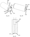
- Fig. 2B illustrates the screw cap 200 from Fig. 2A in a cross section along the axis A-A.
- the screw cap 200 comprises a number of threads on the inner surface 222 of the first raised annular portion 220 which are of which a first and a second thread 252 and 254 are shown, which make it possible to screw the cap 200 onto complementary threads arranged on a neck portion of a packaging container and thus close the container.
- the threads are descending when seen from the bottom surface 212 in the direction of the neck portion of a packaging container (not shown).
- the threads and the engagement portions 240 are aligned such that the starting point of each thread, the starting point 255 of the second thread 254, for example, is vertically aligned with one end of the protrusion 242 of the engagement portion 240.
- the significance of this arrangement will be described later in the text.
- the purpose of the engagement portion 240 is to engage a corresponding cap loading tool, such as a loading piston 300 in order for the shoulder portion arranged on the top part of the loading piston 300 to be able to engage the engagement portion 240.
- the locked screw cap position can be used in a later screw cap application process to hit the starting point of a complementary threaded neck portion of a packaging container.
- Using the protrusion and recesses 242, 244 for the engagement portion 240 in the screw cap has the added advantage that the engagement with a complementary shoulder portion of a loading piston 300 is achieved with very little play.
- the rotational position of the screw cap 200 achieved when being engaged to the loading piston 300 can be determined even more accurately.
- the reduced play between the engagement portion 240 of the screw cap 200 and the shoulder portions of the loading piston 300 will thus increase precision when applying screw cap 200 to a complementary threaded neck portion of a packaging container and therefore achieve better sealing of the container.
- FIGs. 3A-3C Such an exemplary loading tool is illustrated in Figs. 3A-3C . It will be explained later in the text why this is the case.
- Fig. 2C displays the screw cap 200 from Fig. 2A in a cross section along the axis E-E, where especially an enlarged view of one of the engagement portions 240 discussed earlier is illustrated.
- the engagement portion 240 comprises a protrusion 242 having a vertical and a horizontal portion and furthermore one declining portion.
- the protrusion 242 comprises a recess 244 adjacent to the vertical portion of the protrusion 242, where the recess 244 comprises a declining portion and an arcuate portion.
- This structure of the engagement portion ensures that a shoulder portion of a loading piston which is engaged with the engagement portion 240 of the screw cap 200 stays in the arcuate portion of the recess 244 where its further rotational movement is restricted by the vertical portion of the protrusion 242 with very little play. It is however possible to manufacture the screw cap 200 only comprising protrusions as engagement portions, which would allow for some play between the shoulder portion of the loading piston and the engagement portion of the screw cap, but still leading to satisfactory alignment between screw cap and the neck portion of a packaging container.
- Fig. 3A displays an exemplary embodiment of a loading piston 300 which is used as a tool pushing the cap 200 into the chuck and for orienting it.
- the loading piston 300 has a cylindrical shape comprising a cylindrical body 310, a top part 320 and a base 330.
- the top part 320 consists of a conical portion 328 on top of which resides a annular portion 322 which has shoulders 324 arranged along its circumference as complementary engagement portions.
- the loading piston 300 also comprises a recessed portion 326 formed in the top part 320 of the loading piston 300 in order not to contact a slight protrusion in the center of the screw cap see in Fig. 2B for example.
- the function of the shoulders 324 of which three are present in this embodiment of the loading piston 300 is to engage the engagement portions 240 on the screw cap 200 in Fig. 2A .
- the loading piston 300 may have any shape for the complementary engagement portion and any number of these complementary portions which are manufactured so that they are able to engage the engagement portions on the screw cap.
- the engagement means may have different shapes than the ones illustrated in fig. 2D as long as they are able to engage the complementary engagement portions in the loading piston 300 leading to restricted movement of the loading piston 300 in the screw cap when the two are engaged.
- the base 330 of the loading piston 300 comprises a conical bore 336 and conical holes 334 for attachment to a feeding unit which is configured to feed a new screw cap into the screw cap holder 150 described in Fig. 1 .
- a spring (not shown) may be arranged in the conical bore 336 which tension can be used by the servo motor rotating the chuck 150 in relation to the loading piston in order to detect the position of engagement between the shoulder portion 324 of the loading piston 300 and the corresponding engagement portion 240 in the screw cap 200.
- each chuck may be adapted for screwing a cap of different size and possibly adapted in its complementary engagement portion to achieve engagement with different engagement portions in different screw caps.
- Fig. 4 illustrates the steps of a cap orientation method according to one embodiment of the present invention.
- a screw cap When a screw cap is delivered by the loading piston to the chuck in the cap application unit described in Fig. 1 its rotational position with respect to its central axis C-C and its rotational position in relation to the chuck is unknown.
- this undefined rotational relation can lead to misalignment between the screw cap and the complementary threaded portion on the neck of the packaging container when the cap application unit screws the cap onto the neck portion.
- the purpose of cap orientation is thus to achieve a well-defined rotational position of the cap which later can be used for aligned screwing of the cap onto the packaging container.
- a screw cap such as the screw cap 200 illustrated in Figs. 2 A- 2D is loaded onto a piston and held stationary there.
- the piston is moved along the C-C axis towards the chuck.
- a servo motor onto which a chuck such as the chuck 300 illustrated in Figs. 3A-3C , is mounted, brings the chuck into rotation along its central axis after the cap is loaded into the chuck.
- the servo motor onto which the chuck is mounted may move towards a stationary piston onto which the screw cap is loaded or both the servo motor together with the chuck and the piston with the screw cap may move towards each other.
- the servo motor checks whether the engagement portion of the screw cap has come into contact with the complementary engagement portion in the loading tool. This can be detected as a stop of the movement of the chuck if no special means for detecting the building up of torque are arranged. Engagement between the screw cap and the loading tool will also lead to a stop of the servo motor.
- the rotational position of the chuck is then recorded, for example in an internal memory connected to the servo motor. If no engagement between the chuck and the screw cap could be detected, the servo motor stops and proceeds with capping routine without knowing the rotational alignment.
- the screw cap is disengaged from the engagement portion of the loading piston by being rotated by the servo motor in the opposite direction away from engagement.
- step 460 the loading piston is moved in a direction along the central axis C-C away from the chuck and cap.
- Fig. 5 illustrates the screw cap application method according to one embodiment of the present invention in the form of a flow chart.
- the servo motor retrieves the previously saved rotational position of the chuck in relation to the screw cap and rotates the chuck into a new position in relation the saved one so when the cap and neck has engagement they hit each other perfectly aligned.
- the servo motor locks the chuck position to a specific position on the packaging container.
- This can be done with the help of a virtual cam shaft.
- a virtual cam shaft usually, using a real mechanical cam shaft one can determine how other shafts should rotate in relation to the position of the cam shaft.
- such a mechanical cam shaft is made virtual and the other servo motor cam shafts pivot in relation to it. In this way the start of a thread on the screw cap is aligned with a specific rotational position of the neck portion of a packaging container, so that when the cap is screwed onto the neck it hits a predefined spot on the neck portion.
- step 540 the cap is screwed on the packaging container using the steps described in Fig. 1 .
- the engagement portion in the screw cap and the loading piston have been described with respect to one specific embodiment it may be also possible to manufacture the screw cap and the loading piston, such that the engagement portion is located on the outer surface 212 of the screw cap. Also, the engagement portion in the screw cap may need to be vertically aligned with the start of a thread in the cap, but may be located a rotational distance away from it. Likewise, instead of a protrusion and recess being located in the screw cap, they may be located on the loading piston instead, while complementary engagement portions may be located in the screw cap.
Landscapes
- Engineering & Computer Science (AREA)
- Mechanical Engineering (AREA)
- Closures For Containers (AREA)
- Sealing Of Jars (AREA)
- Closing Of Containers (AREA)
Applications Claiming Priority (3)
| Application Number | Priority Date | Filing Date | Title |
|---|---|---|---|
| SE1550070 | 2015-01-23 | ||
| PCT/EP2016/050624 WO2016116344A1 (fr) | 2015-01-23 | 2016-01-14 | Bouchon à vis, outil et procédé de vissage d'un bouchon sur un récipient |
| EP16700477.9A EP3224152B1 (fr) | 2015-01-23 | 2016-01-14 | Bouchon à vis, outil et procédé de vissage d'un bouchon sur un récipient |
Related Parent Applications (1)
| Application Number | Title | Priority Date | Filing Date |
|---|---|---|---|
| EP16700477.9A Division EP3224152B1 (fr) | 2015-01-23 | 2016-01-14 | Bouchon à vis, outil et procédé de vissage d'un bouchon sur un récipient |
Publications (2)
| Publication Number | Publication Date |
|---|---|
| EP4245717A2 true EP4245717A2 (fr) | 2023-09-20 |
| EP4245717A3 EP4245717A3 (fr) | 2023-11-22 |
Family
ID=55129882
Family Applications (3)
| Application Number | Title | Priority Date | Filing Date |
|---|---|---|---|
| EP23175532.3A Pending EP4245717A3 (fr) | 2015-01-23 | 2016-01-14 | Bouchon à vis, outil et procédé de vissage d'un bouchon sur un récipient |
| EP20198660.1A Pending EP3778417A1 (fr) | 2015-01-23 | 2016-01-14 | Capuchon vissé et récipient d'emballage pour produits alimentaires |
| EP16700477.9A Active EP3224152B1 (fr) | 2015-01-23 | 2016-01-14 | Bouchon à vis, outil et procédé de vissage d'un bouchon sur un récipient |
Family Applications After (2)
| Application Number | Title | Priority Date | Filing Date |
|---|---|---|---|
| EP20198660.1A Pending EP3778417A1 (fr) | 2015-01-23 | 2016-01-14 | Capuchon vissé et récipient d'emballage pour produits alimentaires |
| EP16700477.9A Active EP3224152B1 (fr) | 2015-01-23 | 2016-01-14 | Bouchon à vis, outil et procédé de vissage d'un bouchon sur un récipient |
Country Status (20)
| Country | Link |
|---|---|
| US (2) | US11247815B2 (fr) |
| EP (3) | EP4245717A3 (fr) |
| JP (3) | JP6898242B2 (fr) |
| KR (1) | KR20170106336A (fr) |
| CN (4) | CN112320053A (fr) |
| AR (1) | AR103503A1 (fr) |
| AT (1) | AT16942U3 (fr) |
| AU (1) | AU2016208755A1 (fr) |
| BR (1) | BR112017015508B1 (fr) |
| CA (1) | CA2973925A1 (fr) |
| DE (2) | DE202016008905U1 (fr) |
| DK (1) | DK202000065Y4 (fr) |
| ES (1) | ES2950482T3 (fr) |
| HU (1) | HUE062449T2 (fr) |
| MX (1) | MX2017009393A (fr) |
| PL (1) | PL3224152T3 (fr) |
| RS (1) | RS64403B1 (fr) |
| RU (1) | RU2725362C2 (fr) |
| WO (1) | WO2016116344A1 (fr) |
| ZA (1) | ZA201704708B (fr) |
Families Citing this family (8)
| Publication number | Priority date | Publication date | Assignee | Title |
|---|---|---|---|---|
| CA2973925A1 (fr) | 2015-01-23 | 2016-07-28 | Tetra Laval Holdings & Finance S.A. | Bouchon a vis, outil et procede de vissage d'un bouchon sur un recipient |
| WO2016177750A1 (fr) | 2015-05-07 | 2016-11-10 | Tetra Laval Holdings & Finance S.A. | Procédé et appareil d'orientation de capuchon |
| AT519129B1 (de) * | 2017-02-24 | 2018-04-15 | Greiner Packaging Int Gmbh | Schraubkappe mit Orientierungsmittel sowie Orientierungswerkzeug |
| JP7378758B2 (ja) * | 2018-12-27 | 2023-11-14 | 紀伊産業株式会社 | ネジキャップ |
| JP2023535228A (ja) | 2020-04-27 | 2023-08-16 | スヴァリン キャップ システムズ アーゲー | 容器のための閉鎖システム、このような閉鎖システムを備えた容器、このような閉鎖システムを容器に取り付けるためのツール、およびこのような閉鎖システムを容器に取り付けるためのプロセス |
| AU2021280297A1 (en) * | 2020-05-28 | 2023-01-19 | Sonoco Development, Inc. | Systems and methods for the high-speed application of paper-based end closures on composite containers |
| DE202020004567U1 (de) | 2020-10-16 | 2021-01-22 | Paccor Packaging Gmbh | Schraubkappe |
| DE202022106061U1 (de) | 2022-10-27 | 2023-02-02 | Paccor Packaging Gmbh | Schraubkappe |
Citations (3)
| Publication number | Priority date | Publication date | Assignee | Title |
|---|---|---|---|---|
| US2804225A (en) | 1953-05-26 | 1957-08-27 | Ling H Lee | Closure for receptacle |
| US4156491A (en) | 1978-07-10 | 1979-05-29 | Lyon Newton E | Attachment for container closure |
| US7938282B1 (en) | 2008-01-18 | 2011-05-10 | Berlin Packaging, Llc | Closure for a container |
Family Cites Families (56)
| Publication number | Priority date | Publication date | Assignee | Title |
|---|---|---|---|---|
| US2731185A (en) * | 1952-10-31 | 1956-01-17 | California Research Corp | Cap fastener |
| US3979001A (en) * | 1972-12-01 | 1976-09-07 | Clayton Bogert | Safety closure for containers |
| GB1449174A (en) | 1973-05-09 | 1976-09-15 | Metal Box Co Ltd | Closing and sealing containers such as bottles and jars |
| NL181793C (nl) * | 1975-07-01 | 1987-11-02 | Obrist Ag Crown | Houder met een schroefkap. |
| JPS561574Y2 (fr) | 1975-10-02 | 1981-01-14 | ||
| JPS5732123Y2 (fr) * | 1979-06-25 | 1982-07-14 | ||
| DE3108518A1 (de) * | 1981-03-06 | 1982-11-11 | Hans 8801 Schillingsfürst Heinlein | Schraubkappe aus kunststoff mit gewindetoleranzenausgleich |
| US4674263A (en) * | 1985-10-29 | 1987-06-23 | Aluminum Company Of America | Finger assembly for a screwcapping head |
| JPH02282092A (ja) | 1989-04-24 | 1990-11-19 | Kao Corp | キャップ供給方法及びその装置 |
| DE4011398C2 (de) | 1990-04-09 | 1994-09-22 | Alcoa Gmbh Verpackwerke | Vorrichtung und Verfahren zum Aufbringen von Schraubverschlüssen auf Behälter |
| US5048711A (en) * | 1990-06-28 | 1991-09-17 | Sage Products, Inc. | Label indicator for screw thread closure and method of use |
| US5588545A (en) * | 1991-09-23 | 1996-12-31 | Beeson And Sons Limited | Child-resistant and elderly friendly closure for containers |
| US5301488A (en) | 1992-11-06 | 1994-04-12 | National Instrument Company, Inc. | Programmable filling and capping machine |
| JPH0786034B2 (ja) | 1993-03-19 | 1995-09-20 | 澁谷工業株式会社 | キャッピング方法 |
| DE4405950A1 (de) | 1994-02-24 | 1995-08-31 | Hermann Kronseder | Schraubkappe aus Kunststoff für Getränkeflaschen o. dgl. sowie hierfür geeignetes Drehwerkzeug |
| GB2298194A (en) * | 1995-02-24 | 1996-08-28 | Beeson & Sons Ltd | Child resistant closures for containers |
| AUPO788697A0 (en) * | 1997-07-14 | 1997-08-07 | Closures And Packaging Services Limited | Push-on closure |
| JPH11124196A (ja) | 1997-10-22 | 1999-05-11 | Kao Corp | ねじの締付方法及び装置 |
| DE19854709B4 (de) | 1998-11-26 | 2005-08-25 | Polytype S.A. | Befestigung eines Verschlusses an einem Behälter |
| JP4316706B2 (ja) * | 1998-12-16 | 2009-08-19 | 日本クラウンコルク株式会社 | 加熱殺菌乃至滅菌方法 |
| JP2000219261A (ja) | 1999-01-29 | 2000-08-08 | Toppan Printing Co Ltd | 筒状キャップ |
| JP2000327086A (ja) | 1999-05-17 | 2000-11-28 | Shibuya Kogyo Co Ltd | キャッパ |
| JP4232311B2 (ja) | 2000-03-06 | 2009-03-04 | 澁谷工業株式会社 | キャッピング方法とキャッピング装置 |
| JP2002308380A (ja) | 2001-04-13 | 2002-10-23 | Shibuya Kogyo Co Ltd | キャッピング方法とその装置 |
| DE60239245D1 (de) * | 2001-06-20 | 2011-04-07 | Crown Cork Japan | Verfahren zur Prüfung eines auf einer Flasche angebrachtem Verschlusses und Vorrichtung |
| EP1508527A1 (fr) * | 2003-08-20 | 2005-02-23 | H. Obrist & Co. AG | Bouchon de fermeture et kit d'assemblage pour la fabrication d'un dispositif de fermeture sur un tube |
| RU34523U1 (ru) | 2003-09-01 | 2003-12-10 | Общество с ограниченной ответственностью "Серверк" | Устройство для навинчивания резьбовой крышки |
| US7819264B2 (en) * | 2003-12-03 | 2010-10-26 | Rexam Closure Systems Inc. | Child-resistant closure, container and package |
| GB2409200B (en) * | 2003-12-19 | 2007-01-17 | Beeson & Sons Ltd | Bottle and closure assembly with improved locking elements |
| EP1799573B1 (fr) * | 2004-09-01 | 2008-12-10 | Creanova Universal Closures Ltd. | Fermeture |
| US7836669B1 (en) * | 2006-03-09 | 2010-11-23 | The Sherwin Williams Company | Lid applying apparatus and method with lid orienting device |
| SE529720C2 (sv) * | 2006-03-10 | 2007-11-06 | Tetra Laval Holdings & Finance | Metod att tillverka en förpackning |
| JP4912829B2 (ja) * | 2006-10-17 | 2012-04-11 | 日本クラウンコルク株式会社 | 容器蓋 |
| US20080110850A1 (en) * | 2006-11-14 | 2008-05-15 | Andrew Thomas Tilton | Audible closing feature for a threaded container and lid |
| JP2008222239A (ja) * | 2007-03-08 | 2008-09-25 | Alcoa Closure Systems Japan Ltd | キャッピング装置 |
| US8584876B2 (en) * | 2007-07-05 | 2013-11-19 | Kraft Foods Group Brands Llc | Food containers adapted for accommodating pressure changes using skip seals and methods of manufacture |
| GB2467355A (en) * | 2009-01-30 | 2010-08-04 | Beeson & Sons Ltd | Container closure with pressure seal |
| DE102009042109A1 (de) | 2009-09-11 | 2011-04-07 | Closure Systems International Deutschland Gmbh | Verschließmaschine und Verfahren zum Verschließen von Behältern |
| DE102009045637A1 (de) | 2009-10-13 | 2011-04-14 | Krones Ag | Verfahren und Vorrichtung zum Schraubverschließen von Gefäßen, insbesondere Flaschen |
| US8534476B2 (en) * | 2009-12-11 | 2013-09-17 | Rexam Healthcare Packaging Inc. | Child-resistant closure shell, closure, and package |
| DE102009060625A1 (de) | 2009-12-22 | 2011-06-30 | Krones Ag, 93073 | Vorrichtung und Verfahren zum Verschließen von Behältnissen mit Abstandsmessungen |
| JP2011195194A (ja) * | 2010-03-23 | 2011-10-06 | Kaihatsu Giken:Kk | キャップ姿勢調整機及びその使用方法 |
| DE102010012858B4 (de) | 2010-03-25 | 2020-07-09 | Packsys Global (Switzerland) Ltd. | Vorrichtung und Verfahren zur rotatorischen Ausrichtung eines Tubenkopfes relativ zu einem Tubenkörper |
| ES1072702Y (es) * | 2010-05-27 | 2010-12-17 | Betapack Sa | Tapon roscado |
| US20110290755A1 (en) * | 2010-05-27 | 2011-12-01 | Silgan White Cap LLC | Closure with impact resistant ribs |
| JP5945503B2 (ja) | 2010-08-09 | 2016-07-05 | 日本山村硝子株式会社 | 樹脂製キャップ |
| JP5853357B2 (ja) * | 2010-10-07 | 2016-02-09 | 東洋製罐株式会社 | キャップおよびその位置決め方法 |
| US8746486B2 (en) * | 2011-04-15 | 2014-06-10 | Eveready Battery Company, Inc. | Bowl with lid |
| GB201200726D0 (en) * | 2012-01-17 | 2012-02-29 | Crown Packaging Technology | A screw lid for a food container |
| CN102701124B (zh) * | 2012-05-21 | 2014-05-07 | 贵州大学 | 高适应度及高可靠性旋盖方法及其装置 |
| US20130313218A1 (en) * | 2012-05-22 | 2013-11-28 | Christopher A. Cox | Bottle Closures and Containment Systems |
| ITMO20120253A1 (it) * | 2012-10-18 | 2014-04-19 | Sacmi | Tappo per contenitori. |
| CN105247857A (zh) | 2013-04-22 | 2016-01-13 | 派拉斯科技术公司 | 盖分析技术 |
| ITTO20130644A1 (it) | 2013-07-30 | 2015-01-31 | Arol Spa | Macchina per l'applicazione di capsule filettate a contenitori |
| CA2973925A1 (fr) | 2015-01-23 | 2016-07-28 | Tetra Laval Holdings & Finance S.A. | Bouchon a vis, outil et procede de vissage d'un bouchon sur un recipient |
| WO2017212454A1 (fr) * | 2016-06-09 | 2017-12-14 | Glaxosmithkline Consumer Healthcare (Uk) Ip Limited | Ensemble couvercle inviolable |
-
2016
- 2016-01-14 CA CA2973925A patent/CA2973925A1/fr not_active Abandoned
- 2016-01-14 RS RS20230578A patent/RS64403B1/sr unknown
- 2016-01-14 EP EP23175532.3A patent/EP4245717A3/fr active Pending
- 2016-01-14 AT ATGM73/2020U patent/AT16942U3/de unknown
- 2016-01-14 BR BR112017015508-7A patent/BR112017015508B1/pt active IP Right Grant
- 2016-01-14 CN CN202010801630.4A patent/CN112320053A/zh active Pending
- 2016-01-14 CN CN202010801499.1A patent/CN112340213B/zh active Active
- 2016-01-14 CN CN202010801569.3A patent/CN112320052A/zh active Pending
- 2016-01-14 JP JP2017538633A patent/JP6898242B2/ja active Active
- 2016-01-14 AU AU2016208755A patent/AU2016208755A1/en not_active Abandoned
- 2016-01-14 ES ES16700477T patent/ES2950482T3/es active Active
- 2016-01-14 MX MX2017009393A patent/MX2017009393A/es unknown
- 2016-01-14 EP EP20198660.1A patent/EP3778417A1/fr active Pending
- 2016-01-14 PL PL16700477.9T patent/PL3224152T3/pl unknown
- 2016-01-14 HU HUE16700477A patent/HUE062449T2/hu unknown
- 2016-01-14 DE DE202016008905.7U patent/DE202016008905U1/de active Active
- 2016-01-14 RU RU2017129697A patent/RU2725362C2/ru active
- 2016-01-14 KR KR1020177019873A patent/KR20170106336A/ko unknown
- 2016-01-14 CN CN201680007036.XA patent/CN107207130B/zh active Active
- 2016-01-14 DE DE202016008904.9U patent/DE202016008904U1/de active Active
- 2016-01-14 EP EP16700477.9A patent/EP3224152B1/fr active Active
- 2016-01-14 US US15/545,650 patent/US11247815B2/en active Active
- 2016-01-14 WO PCT/EP2016/050624 patent/WO2016116344A1/fr active Application Filing
- 2016-01-22 AR ARP160100182A patent/AR103503A1/es unknown
-
2017
- 2017-07-12 ZA ZA2017/04708A patent/ZA201704708B/en unknown
-
2020
- 2020-06-26 DK DKBA202000065U patent/DK202000065Y4/da active IP Right Grant
- 2020-07-28 JP JP2020127568A patent/JP2020186064A/ja active Pending
-
2021
- 2021-12-20 US US17/645,287 patent/US20220185546A1/en active Pending
-
2023
- 2023-05-17 JP JP2023081157A patent/JP2023103384A/ja active Pending
Patent Citations (3)
| Publication number | Priority date | Publication date | Assignee | Title |
|---|---|---|---|---|
| US2804225A (en) | 1953-05-26 | 1957-08-27 | Ling H Lee | Closure for receptacle |
| US4156491A (en) | 1978-07-10 | 1979-05-29 | Lyon Newton E | Attachment for container closure |
| US7938282B1 (en) | 2008-01-18 | 2011-05-10 | Berlin Packaging, Llc | Closure for a container |
Also Published As
Similar Documents
| Publication | Publication Date | Title |
|---|---|---|
| EP4245717A2 (fr) | Bouchon à vis, outil et procédé de vissage d'un bouchon sur un récipient | |
| US8720744B2 (en) | Closeable opening device for a sealed package | |
| CN102673859B (zh) | 用于可倾倒食品包装的可再封开口装置 | |
| EP1996502B1 (fr) | Procédé de production d'un emballage | |
| US4898295A (en) | Spin welded, tamper-proof, resealable thermoplastic container | |
| US10214305B2 (en) | Assembly machine adapted to assemble caps onto spouts and a method of assembling caps onto spouts | |
| CN107635908B (zh) | 盖定位的方法和装置 | |
| JP6874480B2 (ja) | キャッパ | |
| EP3647221A1 (fr) | Orientation angulaire de capuchon | |
| EP3476762A1 (fr) | Recipient avec mecanisme ameliore de scellage, d'ouverture et de fermeture | |
| JP2022059980A (ja) | 封止装置および封止装置付き容器 | |
| EP3178779A1 (fr) | Appareil et procédé pour étancher des récipients | |
| JPH0729669B2 (ja) | 樹脂ボトルの密封装置 |
Legal Events
| Date | Code | Title | Description |
|---|---|---|---|
| PUAI | Public reference made under article 153(3) epc to a published international application that has entered the european phase |
Free format text: ORIGINAL CODE: 0009012 |
|
| STAA | Information on the status of an ep patent application or granted ep patent |
Free format text: STATUS: REQUEST FOR EXAMINATION WAS MADE |
|
| 17P | Request for examination filed |
Effective date: 20230526 |
|
| AC | Divisional application: reference to earlier application |
Ref document number: 3224152 Country of ref document: EP Kind code of ref document: P |
|
| AK | Designated contracting states |
Kind code of ref document: A2 Designated state(s): AL AT BE BG CH CY CZ DE DK EE ES FI FR GB GR HR HU IE IS IT LI LT LU LV MC MK MT NL NO PL PT RO RS SE SI SK SM TR |
|
| REG | Reference to a national code |
Ref country code: DE Ref legal event code: R079 Free format text: PREVIOUS MAIN CLASS: B67B0003060000 Ipc: B65D0041040000 |
|
| PUAL | Search report despatched |
Free format text: ORIGINAL CODE: 0009013 |
|
| AK | Designated contracting states |
Kind code of ref document: A3 Designated state(s): AL AT BE BG CH CY CZ DE DK EE ES FI FR GB GR HR HU IE IS IT LI LT LU LV MC MK MT NL NO PL PT RO RS SE SI SK SM TR |
|
| RIC1 | Information provided on ipc code assigned before grant |
Ipc: B67B 3/06 20060101ALI20231018BHEP Ipc: B65D 41/04 20060101AFI20231018BHEP |