EP4209686B1 - Hydraulische druckausgeglichene pumpe, drehzahlsteuerungssystem und baumaschine - Google Patents
Hydraulische druckausgeglichene pumpe, drehzahlsteuerungssystem und baumaschine Download PDFInfo
- Publication number
- EP4209686B1 EP4209686B1 EP21874322.7A EP21874322A EP4209686B1 EP 4209686 B1 EP4209686 B1 EP 4209686B1 EP 21874322 A EP21874322 A EP 21874322A EP 4209686 B1 EP4209686 B1 EP 4209686B1
- Authority
- EP
- European Patent Office
- Prior art keywords
- pressure
- hydraulic pump
- oil
- hydraulic
- path
- Prior art date
- Legal status (The legal status is an assumption and is not a legal conclusion. Google has not performed a legal analysis and makes no representation as to the accuracy of the status listed.)
- Active
Links
Images


Classifications
-
- F—MECHANICAL ENGINEERING; LIGHTING; HEATING; WEAPONS; BLASTING
- F15—FLUID-PRESSURE ACTUATORS; HYDRAULICS OR PNEUMATICS IN GENERAL
- F15B—SYSTEMS ACTING BY MEANS OF FLUIDS IN GENERAL; FLUID-PRESSURE ACTUATORS, e.g. SERVOMOTORS; DETAILS OF FLUID-PRESSURE SYSTEMS, NOT OTHERWISE PROVIDED FOR
- F15B11/00—Servomotor systems without provision for follow-up action; Circuits therefor
- F15B11/02—Systems essentially incorporating special features for controlling the speed or actuating force of an output member
- F15B11/04—Systems essentially incorporating special features for controlling the speed or actuating force of an output member for controlling the speed
- F15B11/05—Systems essentially incorporating special features for controlling the speed or actuating force of an output member for controlling the speed specially adapted to maintain constant speed, e.g. pressure-compensated, load-responsive
- F15B11/055—Systems essentially incorporating special features for controlling the speed or actuating force of an output member for controlling the speed specially adapted to maintain constant speed, e.g. pressure-compensated, load-responsive by adjusting the pump output or bypass
-
- F—MECHANICAL ENGINEERING; LIGHTING; HEATING; WEAPONS; BLASTING
- F15—FLUID-PRESSURE ACTUATORS; HYDRAULICS OR PNEUMATICS IN GENERAL
- F15B—SYSTEMS ACTING BY MEANS OF FLUIDS IN GENERAL; FLUID-PRESSURE ACTUATORS, e.g. SERVOMOTORS; DETAILS OF FLUID-PRESSURE SYSTEMS, NOT OTHERWISE PROVIDED FOR
- F15B21/00—Common features of fluid actuator systems; Fluid-pressure actuator systems or details thereof, not covered by any other group of this subclass
- F15B21/08—Servomotor systems incorporating electrically operated control means
- F15B21/087—Control strategy, e.g. with block diagram
-
- E—FIXED CONSTRUCTIONS
- E02—HYDRAULIC ENGINEERING; FOUNDATIONS; SOIL SHIFTING
- E02F—DREDGING; SOIL-SHIFTING
- E02F9/00—Component parts of dredgers or soil-shifting machines, not restricted to one of the kinds covered by groups E02F3/00 - E02F7/00
- E02F9/20—Drives; Control devices
- E02F9/22—Hydraulic or pneumatic drives
- E02F9/2221—Control of flow rate; Load sensing arrangements
- E02F9/2232—Control of flow rate; Load sensing arrangements using one or more variable displacement pumps
- E02F9/2235—Control of flow rate; Load sensing arrangements using one or more variable displacement pumps including an electronic controller
-
- E—FIXED CONSTRUCTIONS
- E02—HYDRAULIC ENGINEERING; FOUNDATIONS; SOIL SHIFTING
- E02F—DREDGING; SOIL-SHIFTING
- E02F9/00—Component parts of dredgers or soil-shifting machines, not restricted to one of the kinds covered by groups E02F3/00 - E02F7/00
- E02F9/20—Drives; Control devices
- E02F9/22—Hydraulic or pneumatic drives
- E02F9/226—Safety arrangements, e.g. hydraulic driven fans, preventing cavitation, leakage, overheating
-
- E—FIXED CONSTRUCTIONS
- E02—HYDRAULIC ENGINEERING; FOUNDATIONS; SOIL SHIFTING
- E02F—DREDGING; SOIL-SHIFTING
- E02F9/00—Component parts of dredgers or soil-shifting machines, not restricted to one of the kinds covered by groups E02F3/00 - E02F7/00
- E02F9/20—Drives; Control devices
- E02F9/22—Hydraulic or pneumatic drives
- E02F9/2278—Hydraulic circuits
- E02F9/2296—Systems with a variable displacement pump
-
- F—MECHANICAL ENGINEERING; LIGHTING; HEATING; WEAPONS; BLASTING
- F04—POSITIVE - DISPLACEMENT MACHINES FOR LIQUIDS; PUMPS FOR LIQUIDS OR ELASTIC FLUIDS
- F04B—POSITIVE-DISPLACEMENT MACHINES FOR LIQUIDS; PUMPS
- F04B23/00—Pumping installations or systems
- F04B23/02—Pumping installations or systems having reservoirs
-
- F—MECHANICAL ENGINEERING; LIGHTING; HEATING; WEAPONS; BLASTING
- F04—POSITIVE - DISPLACEMENT MACHINES FOR LIQUIDS; PUMPS FOR LIQUIDS OR ELASTIC FLUIDS
- F04B—POSITIVE-DISPLACEMENT MACHINES FOR LIQUIDS; PUMPS
- F04B49/00—Control, e.g. of pump delivery, or pump pressure of, or safety measures for, machines, pumps, or pumping installations, not otherwise provided for, or of interest apart from, groups F04B1/00 - F04B47/00
- F04B49/06—Control using electricity
- F04B49/065—Control using electricity and making use of computers
-
- F—MECHANICAL ENGINEERING; LIGHTING; HEATING; WEAPONS; BLASTING
- F04—POSITIVE - DISPLACEMENT MACHINES FOR LIQUIDS; PUMPS FOR LIQUIDS OR ELASTIC FLUIDS
- F04B—POSITIVE-DISPLACEMENT MACHINES FOR LIQUIDS; PUMPS
- F04B49/00—Control, e.g. of pump delivery, or pump pressure of, or safety measures for, machines, pumps, or pumping installations, not otherwise provided for, or of interest apart from, groups F04B1/00 - F04B47/00
- F04B49/20—Control, e.g. of pump delivery, or pump pressure of, or safety measures for, machines, pumps, or pumping installations, not otherwise provided for, or of interest apart from, groups F04B1/00 - F04B47/00 by changing the driving speed
-
- F—MECHANICAL ENGINEERING; LIGHTING; HEATING; WEAPONS; BLASTING
- F15—FLUID-PRESSURE ACTUATORS; HYDRAULICS OR PNEUMATICS IN GENERAL
- F15B—SYSTEMS ACTING BY MEANS OF FLUIDS IN GENERAL; FLUID-PRESSURE ACTUATORS, e.g. SERVOMOTORS; DETAILS OF FLUID-PRESSURE SYSTEMS, NOT OTHERWISE PROVIDED FOR
- F15B11/00—Servomotor systems without provision for follow-up action; Circuits therefor
- F15B11/02—Systems essentially incorporating special features for controlling the speed or actuating force of an output member
- F15B11/04—Systems essentially incorporating special features for controlling the speed or actuating force of an output member for controlling the speed
- F15B11/042—Systems essentially incorporating special features for controlling the speed or actuating force of an output member for controlling the speed by means in the feed line, i.e. "meter in"
- F15B11/0426—Systems essentially incorporating special features for controlling the speed or actuating force of an output member for controlling the speed by means in the feed line, i.e. "meter in" by controlling the number of pumps or parallel valves switched on
-
- F—MECHANICAL ENGINEERING; LIGHTING; HEATING; WEAPONS; BLASTING
- F15—FLUID-PRESSURE ACTUATORS; HYDRAULICS OR PNEUMATICS IN GENERAL
- F15B—SYSTEMS ACTING BY MEANS OF FLUIDS IN GENERAL; FLUID-PRESSURE ACTUATORS, e.g. SERVOMOTORS; DETAILS OF FLUID-PRESSURE SYSTEMS, NOT OTHERWISE PROVIDED FOR
- F15B11/00—Servomotor systems without provision for follow-up action; Circuits therefor
- F15B11/02—Systems essentially incorporating special features for controlling the speed or actuating force of an output member
- F15B11/04—Systems essentially incorporating special features for controlling the speed or actuating force of an output member for controlling the speed
- F15B11/05—Systems essentially incorporating special features for controlling the speed or actuating force of an output member for controlling the speed specially adapted to maintain constant speed, e.g. pressure-compensated, load-responsive
-
- F—MECHANICAL ENGINEERING; LIGHTING; HEATING; WEAPONS; BLASTING
- F15—FLUID-PRESSURE ACTUATORS; HYDRAULICS OR PNEUMATICS IN GENERAL
- F15B—SYSTEMS ACTING BY MEANS OF FLUIDS IN GENERAL; FLUID-PRESSURE ACTUATORS, e.g. SERVOMOTORS; DETAILS OF FLUID-PRESSURE SYSTEMS, NOT OTHERWISE PROVIDED FOR
- F15B13/00—Details of servomotor systems ; Valves for servomotor systems
- F15B13/02—Fluid distribution or supply devices characterised by their adaptation to the control of servomotors
- F15B13/021—Valves for interconnecting the fluid chambers of an actuator
-
- F—MECHANICAL ENGINEERING; LIGHTING; HEATING; WEAPONS; BLASTING
- F15—FLUID-PRESSURE ACTUATORS; HYDRAULICS OR PNEUMATICS IN GENERAL
- F15B—SYSTEMS ACTING BY MEANS OF FLUIDS IN GENERAL; FLUID-PRESSURE ACTUATORS, e.g. SERVOMOTORS; DETAILS OF FLUID-PRESSURE SYSTEMS, NOT OTHERWISE PROVIDED FOR
- F15B21/00—Common features of fluid actuator systems; Fluid-pressure actuator systems or details thereof, not covered by any other group of this subclass
- F15B21/04—Special measures taken in connection with the properties of the fluid
- F15B21/042—Controlling the temperature of the fluid
- F15B21/0423—Cooling
-
- F—MECHANICAL ENGINEERING; LIGHTING; HEATING; WEAPONS; BLASTING
- F15—FLUID-PRESSURE ACTUATORS; HYDRAULICS OR PNEUMATICS IN GENERAL
- F15B—SYSTEMS ACTING BY MEANS OF FLUIDS IN GENERAL; FLUID-PRESSURE ACTUATORS, e.g. SERVOMOTORS; DETAILS OF FLUID-PRESSURE SYSTEMS, NOT OTHERWISE PROVIDED FOR
- F15B2211/00—Circuits for servomotor systems
- F15B2211/20—Fluid pressure source, e.g. accumulator or variable axial piston pump
- F15B2211/205—Systems with pumps
- F15B2211/20507—Type of prime mover
- F15B2211/20523—Internal combustion engine
-
- F—MECHANICAL ENGINEERING; LIGHTING; HEATING; WEAPONS; BLASTING
- F15—FLUID-PRESSURE ACTUATORS; HYDRAULICS OR PNEUMATICS IN GENERAL
- F15B—SYSTEMS ACTING BY MEANS OF FLUIDS IN GENERAL; FLUID-PRESSURE ACTUATORS, e.g. SERVOMOTORS; DETAILS OF FLUID-PRESSURE SYSTEMS, NOT OTHERWISE PROVIDED FOR
- F15B2211/00—Circuits for servomotor systems
- F15B2211/20—Fluid pressure source, e.g. accumulator or variable axial piston pump
- F15B2211/205—Systems with pumps
- F15B2211/2053—Type of pump
- F15B2211/20546—Type of pump variable capacity
- F15B2211/20553—Type of pump variable capacity with pilot circuit, e.g. for controlling a swash plate
-
- F—MECHANICAL ENGINEERING; LIGHTING; HEATING; WEAPONS; BLASTING
- F15—FLUID-PRESSURE ACTUATORS; HYDRAULICS OR PNEUMATICS IN GENERAL
- F15B—SYSTEMS ACTING BY MEANS OF FLUIDS IN GENERAL; FLUID-PRESSURE ACTUATORS, e.g. SERVOMOTORS; DETAILS OF FLUID-PRESSURE SYSTEMS, NOT OTHERWISE PROVIDED FOR
- F15B2211/00—Circuits for servomotor systems
- F15B2211/20—Fluid pressure source, e.g. accumulator or variable axial piston pump
- F15B2211/255—Flow control functions
-
- F—MECHANICAL ENGINEERING; LIGHTING; HEATING; WEAPONS; BLASTING
- F15—FLUID-PRESSURE ACTUATORS; HYDRAULICS OR PNEUMATICS IN GENERAL
- F15B—SYSTEMS ACTING BY MEANS OF FLUIDS IN GENERAL; FLUID-PRESSURE ACTUATORS, e.g. SERVOMOTORS; DETAILS OF FLUID-PRESSURE SYSTEMS, NOT OTHERWISE PROVIDED FOR
- F15B2211/00—Circuits for servomotor systems
- F15B2211/30—Directional control
- F15B2211/305—Directional control characterised by the type of valves
- F15B2211/30525—Directional control valves, e.g. 4/3-directional control valve
-
- F—MECHANICAL ENGINEERING; LIGHTING; HEATING; WEAPONS; BLASTING
- F15—FLUID-PRESSURE ACTUATORS; HYDRAULICS OR PNEUMATICS IN GENERAL
- F15B—SYSTEMS ACTING BY MEANS OF FLUIDS IN GENERAL; FLUID-PRESSURE ACTUATORS, e.g. SERVOMOTORS; DETAILS OF FLUID-PRESSURE SYSTEMS, NOT OTHERWISE PROVIDED FOR
- F15B2211/00—Circuits for servomotor systems
- F15B2211/30—Directional control
- F15B2211/32—Directional control characterised by the type of actuation
- F15B2211/327—Directional control characterised by the type of actuation electrically or electronically
-
- F—MECHANICAL ENGINEERING; LIGHTING; HEATING; WEAPONS; BLASTING
- F15—FLUID-PRESSURE ACTUATORS; HYDRAULICS OR PNEUMATICS IN GENERAL
- F15B—SYSTEMS ACTING BY MEANS OF FLUIDS IN GENERAL; FLUID-PRESSURE ACTUATORS, e.g. SERVOMOTORS; DETAILS OF FLUID-PRESSURE SYSTEMS, NOT OTHERWISE PROVIDED FOR
- F15B2211/00—Circuits for servomotor systems
- F15B2211/50—Pressure control
- F15B2211/505—Pressure control characterised by the type of pressure control means
- F15B2211/50509—Pressure control characterised by the type of pressure control means the pressure control means controlling a pressure upstream of the pressure control means
-
- F—MECHANICAL ENGINEERING; LIGHTING; HEATING; WEAPONS; BLASTING
- F15—FLUID-PRESSURE ACTUATORS; HYDRAULICS OR PNEUMATICS IN GENERAL
- F15B—SYSTEMS ACTING BY MEANS OF FLUIDS IN GENERAL; FLUID-PRESSURE ACTUATORS, e.g. SERVOMOTORS; DETAILS OF FLUID-PRESSURE SYSTEMS, NOT OTHERWISE PROVIDED FOR
- F15B2211/00—Circuits for servomotor systems
- F15B2211/50—Pressure control
- F15B2211/52—Pressure control characterised by the type of actuation
- F15B2211/526—Pressure control characterised by the type of actuation electrically or electronically
-
- F—MECHANICAL ENGINEERING; LIGHTING; HEATING; WEAPONS; BLASTING
- F15—FLUID-PRESSURE ACTUATORS; HYDRAULICS OR PNEUMATICS IN GENERAL
- F15B—SYSTEMS ACTING BY MEANS OF FLUIDS IN GENERAL; FLUID-PRESSURE ACTUATORS, e.g. SERVOMOTORS; DETAILS OF FLUID-PRESSURE SYSTEMS, NOT OTHERWISE PROVIDED FOR
- F15B2211/00—Circuits for servomotor systems
- F15B2211/50—Pressure control
- F15B2211/575—Pilot pressure control
-
- F—MECHANICAL ENGINEERING; LIGHTING; HEATING; WEAPONS; BLASTING
- F15—FLUID-PRESSURE ACTUATORS; HYDRAULICS OR PNEUMATICS IN GENERAL
- F15B—SYSTEMS ACTING BY MEANS OF FLUIDS IN GENERAL; FLUID-PRESSURE ACTUATORS, e.g. SERVOMOTORS; DETAILS OF FLUID-PRESSURE SYSTEMS, NOT OTHERWISE PROVIDED FOR
- F15B2211/00—Circuits for servomotor systems
- F15B2211/60—Circuit components or control therefor
- F15B2211/62—Cooling or heating means
-
- F—MECHANICAL ENGINEERING; LIGHTING; HEATING; WEAPONS; BLASTING
- F15—FLUID-PRESSURE ACTUATORS; HYDRAULICS OR PNEUMATICS IN GENERAL
- F15B—SYSTEMS ACTING BY MEANS OF FLUIDS IN GENERAL; FLUID-PRESSURE ACTUATORS, e.g. SERVOMOTORS; DETAILS OF FLUID-PRESSURE SYSTEMS, NOT OTHERWISE PROVIDED FOR
- F15B2211/00—Circuits for servomotor systems
- F15B2211/60—Circuit components or control therefor
- F15B2211/63—Electronic controllers
- F15B2211/6303—Electronic controllers using input signals
- F15B2211/6306—Electronic controllers using input signals representing a pressure
- F15B2211/6313—Electronic controllers using input signals representing a pressure the pressure being a load pressure
-
- F—MECHANICAL ENGINEERING; LIGHTING; HEATING; WEAPONS; BLASTING
- F15—FLUID-PRESSURE ACTUATORS; HYDRAULICS OR PNEUMATICS IN GENERAL
- F15B—SYSTEMS ACTING BY MEANS OF FLUIDS IN GENERAL; FLUID-PRESSURE ACTUATORS, e.g. SERVOMOTORS; DETAILS OF FLUID-PRESSURE SYSTEMS, NOT OTHERWISE PROVIDED FOR
- F15B2211/00—Circuits for servomotor systems
- F15B2211/60—Circuit components or control therefor
- F15B2211/63—Electronic controllers
- F15B2211/6303—Electronic controllers using input signals
- F15B2211/6343—Electronic controllers using input signals representing a temperature
-
- F—MECHANICAL ENGINEERING; LIGHTING; HEATING; WEAPONS; BLASTING
- F15—FLUID-PRESSURE ACTUATORS; HYDRAULICS OR PNEUMATICS IN GENERAL
- F15B—SYSTEMS ACTING BY MEANS OF FLUIDS IN GENERAL; FLUID-PRESSURE ACTUATORS, e.g. SERVOMOTORS; DETAILS OF FLUID-PRESSURE SYSTEMS, NOT OTHERWISE PROVIDED FOR
- F15B2211/00—Circuits for servomotor systems
- F15B2211/60—Circuit components or control therefor
- F15B2211/665—Methods of control using electronic components
- F15B2211/6652—Control of the pressure source, e.g. control of the swash plate angle
-
- F—MECHANICAL ENGINEERING; LIGHTING; HEATING; WEAPONS; BLASTING
- F15—FLUID-PRESSURE ACTUATORS; HYDRAULICS OR PNEUMATICS IN GENERAL
- F15B—SYSTEMS ACTING BY MEANS OF FLUIDS IN GENERAL; FLUID-PRESSURE ACTUATORS, e.g. SERVOMOTORS; DETAILS OF FLUID-PRESSURE SYSTEMS, NOT OTHERWISE PROVIDED FOR
- F15B2211/00—Circuits for servomotor systems
- F15B2211/60—Circuit components or control therefor
- F15B2211/665—Methods of control using electronic components
- F15B2211/6654—Flow rate control
-
- F—MECHANICAL ENGINEERING; LIGHTING; HEATING; WEAPONS; BLASTING
- F15—FLUID-PRESSURE ACTUATORS; HYDRAULICS OR PNEUMATICS IN GENERAL
- F15B—SYSTEMS ACTING BY MEANS OF FLUIDS IN GENERAL; FLUID-PRESSURE ACTUATORS, e.g. SERVOMOTORS; DETAILS OF FLUID-PRESSURE SYSTEMS, NOT OTHERWISE PROVIDED FOR
- F15B2211/00—Circuits for servomotor systems
- F15B2211/70—Output members, e.g. hydraulic motors or cylinders or control therefor
- F15B2211/705—Output members, e.g. hydraulic motors or cylinders or control therefor characterised by the type of output members or actuators
- F15B2211/7058—Rotary output members
Definitions
- first”, “second” and “third” are only for a descriptive purpose, but shall not be understood as indicating or implying relative importance or implicitly indicating the quantity of the indicated technical features. Therefore, features defined by “first”, “second” or “third” may expressly or impliedly include one or more features.
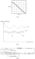
- the control method can adjust the displacement of the hydraulic pump in real time when the rotation speed of the hydraulic pump varies, so that the output flow rate of the hydraulic pump is essentially stabilized at a demand value, thereby the rotation speed of a heat dissipation device driven by the hydraulic pump is stabilized at a demand value, and the operation of the heat dissipation device is more stable.
- the displacement control mechanism of the hydraulic system comprises an electric proportional pressure compensator, a corresponding current value is obtained according to the oil temperature of the hydraulic oil, and a current value is inputted into the electric proportional pressure compensator to control an opening pressure of the electric proportional pressure compensator, wherein the opening pressure is a first pressure value.
- a pressure comparison module of the hydraulic system comprises a servo cylinder 13 for controlling the displacement and a hydraulic control reversing valve 12 for controlling the servo cylinder 13 to extend and retract, and the first pressure value and the second pressure value act on hydraulic control ports at the two ends of the hydraulic control reversing valve 12 respectively; the valve spool of the hydraulic control reversing valve 12 can move to the smaller one of the first pressure value and the second pressure value, thereby the first pressure value is compared with the second pressure value.
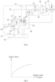
- the pressure-compensation controlled hydraulic pump comprises an electric proportional pressure compensator 14, a hydraulic pump 11, a hydraulic control reversing valve 12, and a servo cylinder 13 for adjusting the displacement of the hydraulic pump 11.
- the electric proportional pressure compensator 14 is electrically connected to a controller 15, so as to adjust an opening pressure of the electric proportional pressure compensator 14 via the controller 15.
- the electric proportional pressure compensator 14 employs an inversely proportional control mode, i.e., the opening pressure can be decreased by increasing the current.
- the oil outlet of the hydraulic pump is connected to an internal output oil path 22, the oil inlet of the hydraulic pump is connected to an internal input oil path 21, a power drive device 34 is connected to the hydraulic pump 11 to supply power to the hydraulic pump 11; thus, variations of the rotation speed of the power drive device 34 lead to variations of the rotation speed of the hydraulic pump 11 and further affect the output flow rate of the hydraulic pump 11; the hydraulic pump 11 can drive an connected actuator element via a hydraulic circuit, and fluctuations of the output flow rate of the hydraulic pump 11 lead to fluctuations of the rotation speed of the actuator element.
- a piston chamber of the servo cylinder 13 is connected to the internal output oil path 22 and the internal oil drain path 23 respectively via the hydraulic control reversing valve 12, a pressure difference between an opening pressure of the electric proportional pressure compensator 14 and the pressure at the oil outlet of the hydraulic pump acts on a valve spool of the hydraulic control reversing valve 12 via the first hydraulic control port 121 and the second hydraulic control port 122 to drive the hydraulic control reversing valve 12 to perform reversing, thereby selectively enables the piston chamber of the servo cylinder 13 to be in communication with the internal output oil path 22 or the internal oil drain path 23; the oil input into the piston chamber of the servo cylinder 13 or oil output from the piston chamber of the servo cylinder 13 makes a push rod of the servo cylinder 13 extend or retract, thereby adjusts the displacement of the hydraulic pump 11 by adjusting the inclination angle of a swash plate of the hydraulic pump 11.
- the hydraulic pump 11 is a variable displacement plunger pump, the displacement of which can be adjusted more conveniently.
- the push rod of the servo cylinder 13 can adjust the displacement of the hydraulic pump 11 by adjusting the inclination angle of a swash plate of the variable displacement plunger pump.
- a second throttle valve 17 is provided in the connection oil path between the piston chamber of the servo cylinder 13 and the hydraulic control reversing valve 12.
- the second throttle valve 17 can adjust the oil inflow rate and oil outflow rate of the piston chamber of the servo cylinder 13; when the flow rate through the second throttle valve 17 is high, the response rate of the pressure-compensation controlled hydraulic pump is high, but the disturbances to the hydraulic oil and the impact on the pipeline in the system are high.
- a safety oil path 25 is connected between the piston chamber of the servo cylinder 13 and the internal oil drain path 23 and is provided with a third throttle valve 18, one end of the safety oil path 25 is connected to the connection oil path between the piston chamber of the servo cylinder 13 and the hydraulic control reversing valve 12, and the connection point is between the first throttle valve 16 and the second throttle valve 17; the other end of the safety oil path 25 is connected to the internal oil drain path 23 at a position after the connection position of the oil outlet of the electric proportional pressure compensator 14.
- the present invention provides a rotation speed control system for a heat dissipation device of a construction machinery, which comprises a temperature sensor 31 for detecting the oil temperature of hydraulic oil, a fan motor 33 for driving a fan 32 to rotate, and a pressure-compensation controlled hydraulic pump, the hydraulic pump 11 of which is connected to a power drive device 34, the power drive device 34 may be a common drive device, such as an engine or electric motor, etc., an internal input oil path 21 and an internal oil drain path 23 are connected to an oil tank 35, a first working oil port A and a second working oil port B of the fan motor 33 are connected to a first working oil path 41 and a second working oil path 42 respectively, the first working oil path 41 and the second working oil path 42 are connected to a main oil inflow path 43 and a main oil return path 44 via a main reversing valve 37 to switch the fan motor 33 to
- the oil tank 35 is a closed-type oil tank, to prevent impurities from mixed into the hydraulic oil and keep the hydraulic oil clean.
Landscapes
- Engineering & Computer Science (AREA)
- General Engineering & Computer Science (AREA)
- Mechanical Engineering (AREA)
- Physics & Mathematics (AREA)
- Fluid Mechanics (AREA)
- Chemical & Material Sciences (AREA)
- Analytical Chemistry (AREA)
- Mining & Mineral Resources (AREA)
- Civil Engineering (AREA)
- Structural Engineering (AREA)
- Computer Hardware Design (AREA)
- Fluid-Pressure Circuits (AREA)
Claims (8)
- Eine druckkompensationsgeregelte Hydraulikpumpe, die eine Drucksteuervorrichtung, eine Hydraulikpumpe (11) und eine Verdrängungseinstellvorrichtung umfasst, wobei die Verdrängungseinstellvorrichtung dazu ausgebildet ist, einen von der Drucksteuervorrichtung erzeugten ersten Druckwert mit einem zweiten Druckwert an einem Ölauslass der Hydraulikpumpe zu vergleichen und die Verdrängung der Hydraulikpumpe (11) entsprechend einem Ergebnis des Vergleichs einzustellen, so dass die Ausgangsdurchflussrate der Hydraulikpumpe (11) innerhalb eines voreingestellten Durchflussratenbereichs stabilisiert wird, wenn die Drehzahl der Hydraulikpumpe (11) variiert,wobei die Verdrängungseinstellvorrichtung ein hydraulisches Steuerumkehrventil (12) und einen Servozylinder (13) zum Einstellen der Verdrängung der Hydraulikpumpe (11) umfasst, der Ölauslass der Hydraulikpumpe mit einem internen Ausgangsölkreislauf (22) verbunden ist, ein Öleinlass der Hydraulikpumpe mit einem internen Eingangsölkreislauf (21) verbunden ist, ein erster hydraulischer Steueranschluss (121) des hydraulischen Steuerumkehrventils (12) über die Drucksteuervorrichtung mit einem internen Ölablasskreislauf (23) verbunden ist, eine Kolbenkammer des Servozylinders (13) über das hydraulische Steuerumkehrventil (12) jeweils mit dem internen Ausgangsölkreislauf (22) und dem internen Ölablasskreislauf (23) verbunden ist, eine Druckdifferenz zwischen der Drucksteuervorrichtung und einem Ölauslassdruck der Hydraulikpumpe auf einen Ventilschieber des hydraulischen Steuerumkehrventils (12) über den ersten hydraulischen Steueranschluss (121) und einen zweiten hydraulischen Steueranschluss (122) des hydraulischen Steuerumkehrventils (12) wirkt, um das hydraulische Steuerumkehrventil (12) zur Durchführung einer Arbeitsumkehrung anzutreiben, wodurch die Kolbenkammer des Servozylinders (13) wahlweise mit dem internen Ausgangsölkreislauf (22) oder dem internen Ölablasskreislauf (23) in Verbindung gebracht werden kann, undwobei der erste hydraulische Steueranschluss (121) über einen mit einem ersten Drosselventil (16) versehenen hydraulischen Steueröleinlasskreislauf (24) mit dem internen Ausgangsölkreislauf (22) verbunden ist, und der zweite hydraulische Steueranschluss (122) des hydraulischen Steuerumkehrventils (12) mit dem internen Ausgangsölkreislauf (22) verbunden ist.
- Druckkompensationsgesteuerte Hydraulikpumpe nach Anspruch 1, wobei die Drucksteuervorrichtung ein elektrischer proportionaler Druckkompensator (14) ist.
- Druckkompensationsgesteuerte Hydraulikpumpe nach Anspruch 1, wobei die Hydraulikpumpe (11) eine Kolbenpumpe mit variabler Verdrängung ist.
- Druckkompensationsgesteuerte Hydraulikpumpe nach Anspruch 1, wobei das hydraulische Steuerumkehrventil (12) ein Zwei-Positionen-Drei-Wege-Umschaltventil ist.
- Druckausgleichsgesteuerte Hydraulikpumpe nach Anspruch 2, wobei ein zweites Drosselventil (17) in einem Verbindungsölkreislauf zwischen der Kolbenkammer des Servozylinders (13) und dem hydraulischen Steuerumkehrventil (12) vorgesehen ist.
- Druckausgleichsgesteuerte Hydraulikpumpe nach Anspruch 5, wobei ein Sicherheitsölkreislauf (25) zwischen der Kolbenkammer des Servozylinders (13) und dem internen Ölablasskreislauf (23) angeschlossen und mit einem dritten Drosselventil (18) versehen ist, wobei ein Ende des Sicherheitsölkreislaufs (25) mit dem Verbindungsölkreislauf zwischen der Kolbenkammer des Servozylinders (13) und dem hydraulischen Steuerumkehrventil (12) verbunden ist und der Verbindungspunkt zwischen dem ersten Drosselventil (16) und dem zweiten Drosselventil (17) angeordnet ist; und wobei das andere Ende des Sicherheitsölkreislaufs (25) mit dem internen Ölablasskreislauf (23) an einer Position nach der Verbindungsposition eines Ölauslasses des elektrischen Proportionaldruckkompensators (14) verbunden ist.
- Drehzahlregelungssystem für eine Wärmeableitungsvorrichtung einer Baumaschine, das einen Temperatursensor (31) zum Erfassen der Öltemperatur von Hydrauliköl, einen Gebläsemotor (33) zum Antreiben eines Gebläses (32) zum Drehen, einen Regler (15) und die druckkompensationsgesteuerte Hydraulikpumpe nach einem der Ansprüche 1 bis 6, wobei der Temperatursensor (31) elektrisch mit dem Regler (15) verbunden ist und der Regler (15) so angeordnet ist, dass er ein Signal vom Temperatursensor (31) empfängt und den von der Druckregelungsvorrichtung erzeugten ersten Druckwert entsprechend dem Signal regelt, und der vom Gebläsemotor (33) beim Antreiben des Gebläses (32) erzeugte Druck zum Ölauslass der Hydraulikpumpe zurückgeführt wird, um den zweiten Druckwert zu bilden.
- Baumaschine, die einen Wärmestrahler zum Kühlen von Hydrauliköl und das Drehzahlregelungssystem für eine Wärmeableitungsvorrichtung einer Baumaschine nach Anspruch 7, wobei der Gebläsemotor (33) so angeordnet ist, dass er das Gebläse (32) zum Drehen antreibt, um den Wärmestrahler zu kühlen.
Applications Claiming Priority (2)
| Application Number | Priority Date | Filing Date | Title |
|---|---|---|---|
| CN202011065237.XA CN112128178B (zh) | 2020-09-30 | 2020-09-30 | 压力补偿式液压泵、转速控制系统及控制方法和工程机械 |
| PCT/CN2021/119804 WO2022068661A1 (zh) | 2020-09-30 | 2021-09-23 | 压力补偿式液压泵、转速控制系统及控制方法和工程机械 |
Publications (3)
| Publication Number | Publication Date |
|---|---|
| EP4209686A1 EP4209686A1 (de) | 2023-07-12 |
| EP4209686A4 EP4209686A4 (de) | 2024-03-06 |
| EP4209686B1 true EP4209686B1 (de) | 2025-04-16 |
Family
ID=73843678
Family Applications (1)
| Application Number | Title | Priority Date | Filing Date |
|---|---|---|---|
| EP21874322.7A Active EP4209686B1 (de) | 2020-09-30 | 2021-09-23 | Hydraulische druckausgeglichene pumpe, drehzahlsteuerungssystem und baumaschine |
Country Status (4)
| Country | Link |
|---|---|
| US (1) | US12516683B2 (de) |
| EP (1) | EP4209686B1 (de) |
| CN (1) | CN112128178B (de) |
| WO (1) | WO2022068661A1 (de) |
Families Citing this family (23)
| Publication number | Priority date | Publication date | Assignee | Title |
|---|---|---|---|---|
| CN112128178B (zh) | 2020-09-30 | 2025-06-06 | 中联重科股份有限公司 | 压力补偿式液压泵、转速控制系统及控制方法和工程机械 |
| CN113107917B (zh) * | 2021-04-09 | 2023-05-23 | 三一重机有限公司 | 电液控制方法、装置及作业机械 |
| CN113187782B (zh) * | 2021-05-07 | 2022-08-02 | 潍柴动力股份有限公司 | 一种闭式液压系统的控制方法、装置、设备及存储介质 |
| CN113983009B (zh) * | 2021-10-28 | 2023-10-27 | 三一重机有限公司 | 风扇转速控制系统、风扇转速控制方法以及工程机械 |
| CN113864277A (zh) * | 2021-10-29 | 2021-12-31 | 三一重机有限公司 | 单向阀、流量过载保护液压系统及作业机械 |
| CN114442691B (zh) * | 2021-12-27 | 2023-10-24 | 中联重科土方机械有限公司 | 用于工程机械的温度控制方法、设备及处理器 |
| CN114233460A (zh) * | 2021-12-28 | 2022-03-25 | 徐州徐工矿业机械有限公司 | 一种工程机械独立散热控制系统及方法 |
| CN114857066B (zh) * | 2022-04-29 | 2023-07-11 | 三一重机有限公司 | 液压驱动风扇控制方法、散热装置及作业机械 |
| CN114754292B (zh) * | 2022-05-05 | 2023-07-14 | 济南林青铸造技术有限公司 | 一种智能控制的液料连续精准定量输出系统及其运行方法 |
| CN114838021A (zh) * | 2022-06-13 | 2022-08-02 | 恒天九五重工有限公司 | 具有自冷却功能的旋挖钻机动力头高低速换挡控制装置 |
| CN114962396A (zh) * | 2022-07-07 | 2022-08-30 | 徐州徐工矿业机械有限公司 | 一种新型挖掘机双变量独立散热液压系统及控制方法 |
| CN115199523B (zh) * | 2022-07-22 | 2023-07-14 | 哈尔滨工业大学 | 一种四象限液压泵变量特性综合测试系统 |
| CN115234544B (zh) * | 2022-07-26 | 2025-05-16 | 哈尔滨工江机电科技有限公司 | 一种变频变幅液压伺服加载装置及加载方法 |
| CN115638151A (zh) * | 2022-09-08 | 2023-01-24 | 江苏徐工工程机械研究院有限公司 | 液压系统的控制方法和液压系统 |
| CN115467750B (zh) * | 2022-10-14 | 2024-03-26 | 中船动力研究院有限公司 | 一种用于柴油发动机的调速系统及调速方法 |
| CN115522592B (zh) * | 2022-10-24 | 2024-06-18 | 中联重科股份有限公司 | 一种挖掘机散热系统及其控制方法 |
| CN116792373A (zh) * | 2023-06-28 | 2023-09-22 | 潍柴雷沃智慧农业科技股份有限公司 | 一种双风机液压系统、双风机除杂装置及甘蔗收获机 |
| CN116838633A (zh) * | 2023-07-21 | 2023-10-03 | 潍柴雷沃智慧农业科技股份有限公司 | 一种发动机反吹风扇节能控制装置及方法 |
| CN116658493B (zh) * | 2023-08-01 | 2023-10-24 | 华侨大学 | 基于变转速与变排量的负流量系统和电动工程机械装置 |
| CN117261142A (zh) * | 2023-09-27 | 2023-12-22 | 东莞拓斯达智能装备有限公司 | 一种注塑机流量补偿方法、装置、设备和介质 |
| CN117468521A (zh) * | 2023-11-24 | 2024-01-30 | 山推工程机械股份有限公司 | 推土机用热管理系统及推土机 |
| CN119163653A (zh) * | 2024-08-09 | 2024-12-20 | 中联重科股份有限公司 | 闭式马达液压回路及其控制方法、作业机械 |
| CN119957573B (zh) * | 2025-02-26 | 2025-11-18 | 常州液压成套设备厂有限公司 | 深潜油泵油缸集成式液压机及其应用方法 |
Family Cites Families (15)
| Publication number | Priority date | Publication date | Assignee | Title |
|---|---|---|---|---|
| DE3805061A1 (de) * | 1988-02-18 | 1989-08-31 | Linde Ag | Hydraulische schaltanordnung |
| JPH09317465A (ja) * | 1996-05-31 | 1997-12-09 | Komatsu Ltd | 冷却用ファンの油圧駆動装置 |
| JP4204137B2 (ja) * | 1999-04-22 | 2009-01-07 | 株式会社小松製作所 | 冷却用ファンの駆動制御装置 |
| EP1967745A4 (de) | 2005-12-27 | 2016-04-20 | Hitachi Construction Machinery | Pumpensteuervorrichtung für hydraulische arbeitsmaschine, pumpensteuerverfahren und baumaschine |
| KR20140109388A (ko) * | 2011-12-23 | 2014-09-15 | 볼보 컨스트럭션 이큅먼트 에이비 | 건설기계용 유압 팬 구동 제어시스템 |
| JP5816601B2 (ja) * | 2012-11-06 | 2015-11-18 | 日立建機株式会社 | 作業機械の冷却装置 |
| CN103591087B (zh) * | 2013-11-18 | 2017-10-27 | 中联重科股份有限公司 | 泵送液压系统的温度控制装置和控制方法、工程机械 |
| CN204003552U (zh) * | 2014-08-04 | 2014-12-10 | 北京市三一重机有限公司 | 液压油散热风扇调速控制系统及工程机械 |
| JP6528673B2 (ja) * | 2015-12-22 | 2019-06-12 | コベルコ建機株式会社 | 油圧式作業機械の作動油温度調節装置 |
| JP6473702B2 (ja) * | 2016-02-01 | 2019-02-20 | 株式会社Kcm | 作業機械 |
| CN106638758A (zh) * | 2016-12-15 | 2017-05-10 | 柳州柳工挖掘机有限公司 | 工程机械风扇控制系统 |
| JP6944270B2 (ja) | 2017-04-10 | 2021-10-06 | ヤンマーパワーテクノロジー株式会社 | 油圧機械の制御装置 |
| CN109695599B (zh) * | 2019-01-31 | 2020-07-28 | 广西柳工机械股份有限公司 | 变量液压系统、泵输出流量控制方法、工程机械 |
| CN213981485U (zh) * | 2020-09-30 | 2021-08-17 | 中联重科股份有限公司 | 压力补偿控制式液压泵、转速控制系统和工程机械 |
| CN112128178B (zh) * | 2020-09-30 | 2025-06-06 | 中联重科股份有限公司 | 压力补偿式液压泵、转速控制系统及控制方法和工程机械 |
-
2020
- 2020-09-30 CN CN202011065237.XA patent/CN112128178B/zh active Active
-
2021
- 2021-09-23 US US18/029,512 patent/US12516683B2/en active Active
- 2021-09-23 EP EP21874322.7A patent/EP4209686B1/de active Active
- 2021-09-23 WO PCT/CN2021/119804 patent/WO2022068661A1/zh not_active Ceased
Also Published As
| Publication number | Publication date |
|---|---|
| WO2022068661A1 (zh) | 2022-04-07 |
| US12516683B2 (en) | 2026-01-06 |
| US20240011602A1 (en) | 2024-01-11 |
| CN112128178A (zh) | 2020-12-25 |
| EP4209686A1 (de) | 2023-07-12 |
| CN112128178B (zh) | 2025-06-06 |
| EP4209686A4 (de) | 2024-03-06 |
Similar Documents
| Publication | Publication Date | Title |
|---|---|---|
| EP4209686B1 (de) | Hydraulische druckausgeglichene pumpe, drehzahlsteuerungssystem und baumaschine | |
| KR101588335B1 (ko) | 유압제어 시스템 | |
| US6481388B1 (en) | Cooling fan drive control device | |
| EP2050970B1 (de) | Hydraulikschaltung für Baumaschinen | |
| US8495871B2 (en) | Hydraulic system | |
| CN213981485U (zh) | 压力补偿控制式液压泵、转速控制系统和工程机械 | |
| US11781288B2 (en) | Shovel | |
| JP2646224B2 (ja) | 少なくとも2つのアクチュエータの流体圧駆動用制御装置 | |
| JP2002081408A (ja) | 流体圧回路 | |
| JP2000130164A (ja) | 冷却用ファンの駆動装置 | |
| KR101648982B1 (ko) | 건설기계의 유압펌프 제어장치 및 제어방법 | |
| US6718763B2 (en) | Hydraulic drive unit | |
| US8429908B2 (en) | Hydraulic system | |
| EP3470677B1 (de) | Pumpvorrichtung | |
| CN218148624U (zh) | 挖掘机散热系统及挖掘机 | |
| CN116658493A (zh) | 基于变转速与变排量的负流量系统和电动工程机械装置 | |
| JPH051768A (ja) | 油圧サーボユニツトの作動制御装置 | |
| JP3081988B2 (ja) | 油圧駆動機械の制御装置 | |
| JP2011184911A (ja) | 冷却ファンの駆動回路 | |
| JPH07293508A (ja) | 油圧制御装置 | |
| JP2794874B2 (ja) | 産業車両の油圧装置 | |
| US12467232B2 (en) | Excavator | |
| JP2006009966A (ja) | 冷却システム | |
| JP3655910B2 (ja) | 油圧駆動機械の制御装置 | |
| JP2009007975A (ja) | 油圧ポンプのインバータ駆動制御方法 |
Legal Events
| Date | Code | Title | Description |
|---|---|---|---|
| STAA | Information on the status of an ep patent application or granted ep patent |
Free format text: STATUS: THE INTERNATIONAL PUBLICATION HAS BEEN MADE |
|
| PUAI | Public reference made under article 153(3) epc to a published international application that has entered the european phase |
Free format text: ORIGINAL CODE: 0009012 |
|
| STAA | Information on the status of an ep patent application or granted ep patent |
Free format text: STATUS: REQUEST FOR EXAMINATION WAS MADE |
|
| 17P | Request for examination filed |
Effective date: 20230404 |
|
| AK | Designated contracting states |
Kind code of ref document: A1 Designated state(s): AL AT BE BG CH CY CZ DE DK EE ES FI FR GB GR HR HU IE IS IT LI LT LU LV MC MK MT NL NO PL PT RO RS SE SI SK SM TR |
|
| DAV | Request for validation of the european patent (deleted) | ||
| DAX | Request for extension of the european patent (deleted) | ||
| REG | Reference to a national code |
Ref country code: DE Ref legal event code: R079 Ref country code: DE Ref legal event code: R079 Ref document number: 602021029384 Country of ref document: DE Free format text: PREVIOUS MAIN CLASS: F15B0021080000 Ipc: F15B0011050000 |
|
| A4 | Supplementary search report drawn up and despatched |
Effective date: 20240201 |
|
| RIC1 | Information provided on ipc code assigned before grant |
Ipc: F15B 21/04 20190101ALI20240126BHEP Ipc: F15B 11/05 20060101AFI20240126BHEP |
|
| GRAP | Despatch of communication of intention to grant a patent |
Free format text: ORIGINAL CODE: EPIDOSNIGR1 |
|
| STAA | Information on the status of an ep patent application or granted ep patent |
Free format text: STATUS: GRANT OF PATENT IS INTENDED |
|
| INTG | Intention to grant announced |
Effective date: 20250130 |
|
| GRAS | Grant fee paid |
Free format text: ORIGINAL CODE: EPIDOSNIGR3 |
|
| GRAA | (expected) grant |
Free format text: ORIGINAL CODE: 0009210 |
|
| STAA | Information on the status of an ep patent application or granted ep patent |
Free format text: STATUS: THE PATENT HAS BEEN GRANTED |
|
| AK | Designated contracting states |
Kind code of ref document: B1 Designated state(s): AL AT BE BG CH CY CZ DE DK EE ES FI FR GB GR HR HU IE IS IT LI LT LU LV MC MK MT NL NO PL PT RO RS SE SI SK SM TR |
|
| REG | Reference to a national code |
Ref country code: GB Ref legal event code: FG4D |
|
| REG | Reference to a national code |
Ref country code: CH Ref legal event code: EP |
|
| REG | Reference to a national code |
Ref country code: IE Ref legal event code: FG4D |
|
| REG | Reference to a national code |
Ref country code: DE Ref legal event code: R096 Ref document number: 602021029384 Country of ref document: DE |
|
| REG | Reference to a national code |
Ref country code: NL Ref legal event code: MP Effective date: 20250416 |
|
| PG25 | Lapsed in a contracting state [announced via postgrant information from national office to epo] |
Ref country code: NL Free format text: LAPSE BECAUSE OF FAILURE TO SUBMIT A TRANSLATION OF THE DESCRIPTION OR TO PAY THE FEE WITHIN THE PRESCRIBED TIME-LIMIT Effective date: 20250416 |
|
| REG | Reference to a national code |
Ref country code: AT Ref legal event code: MK05 Ref document number: 1785859 Country of ref document: AT Kind code of ref document: T Effective date: 20250416 |
|
| PG25 | Lapsed in a contracting state [announced via postgrant information from national office to epo] |
Ref country code: FI Free format text: LAPSE BECAUSE OF FAILURE TO SUBMIT A TRANSLATION OF THE DESCRIPTION OR TO PAY THE FEE WITHIN THE PRESCRIBED TIME-LIMIT Effective date: 20250416 Ref country code: ES Free format text: LAPSE BECAUSE OF FAILURE TO SUBMIT A TRANSLATION OF THE DESCRIPTION OR TO PAY THE FEE WITHIN THE PRESCRIBED TIME-LIMIT Effective date: 20250416 Ref country code: PT Free format text: LAPSE BECAUSE OF FAILURE TO SUBMIT A TRANSLATION OF THE DESCRIPTION OR TO PAY THE FEE WITHIN THE PRESCRIBED TIME-LIMIT Effective date: 20250818 |
|
| PGFP | Annual fee paid to national office [announced via postgrant information from national office to epo] |
Ref country code: DE Payment date: 20250916 Year of fee payment: 5 |
|
| REG | Reference to a national code |
Ref country code: LT Ref legal event code: MG9D |
|
| PG25 | Lapsed in a contracting state [announced via postgrant information from national office to epo] |
Ref country code: NO Free format text: LAPSE BECAUSE OF FAILURE TO SUBMIT A TRANSLATION OF THE DESCRIPTION OR TO PAY THE FEE WITHIN THE PRESCRIBED TIME-LIMIT Effective date: 20250716 Ref country code: GR Free format text: LAPSE BECAUSE OF FAILURE TO SUBMIT A TRANSLATION OF THE DESCRIPTION OR TO PAY THE FEE WITHIN THE PRESCRIBED TIME-LIMIT Effective date: 20250717 |
|
| PG25 | Lapsed in a contracting state [announced via postgrant information from national office to epo] |
Ref country code: PL Free format text: LAPSE BECAUSE OF FAILURE TO SUBMIT A TRANSLATION OF THE DESCRIPTION OR TO PAY THE FEE WITHIN THE PRESCRIBED TIME-LIMIT Effective date: 20250416 |
|
| PGFP | Annual fee paid to national office [announced via postgrant information from national office to epo] |
Ref country code: TR Payment date: 20250910 Year of fee payment: 5 |
|
| PG25 | Lapsed in a contracting state [announced via postgrant information from national office to epo] |
Ref country code: BG Free format text: LAPSE BECAUSE OF FAILURE TO SUBMIT A TRANSLATION OF THE DESCRIPTION OR TO PAY THE FEE WITHIN THE PRESCRIBED TIME-LIMIT Effective date: 20250416 |
|
| PG25 | Lapsed in a contracting state [announced via postgrant information from national office to epo] |
Ref country code: HR Free format text: LAPSE BECAUSE OF FAILURE TO SUBMIT A TRANSLATION OF THE DESCRIPTION OR TO PAY THE FEE WITHIN THE PRESCRIBED TIME-LIMIT Effective date: 20250416 |
|
| PG25 | Lapsed in a contracting state [announced via postgrant information from national office to epo] |
Ref country code: AT Free format text: LAPSE BECAUSE OF FAILURE TO SUBMIT A TRANSLATION OF THE DESCRIPTION OR TO PAY THE FEE WITHIN THE PRESCRIBED TIME-LIMIT Effective date: 20250416 |
|
| PGFP | Annual fee paid to national office [announced via postgrant information from national office to epo] |
Ref country code: FR Payment date: 20250929 Year of fee payment: 5 |
|
| PG25 | Lapsed in a contracting state [announced via postgrant information from national office to epo] |
Ref country code: RS Free format text: LAPSE BECAUSE OF FAILURE TO SUBMIT A TRANSLATION OF THE DESCRIPTION OR TO PAY THE FEE WITHIN THE PRESCRIBED TIME-LIMIT Effective date: 20250716 |
|
| PG25 | Lapsed in a contracting state [announced via postgrant information from national office to epo] |
Ref country code: IS Free format text: LAPSE BECAUSE OF FAILURE TO SUBMIT A TRANSLATION OF THE DESCRIPTION OR TO PAY THE FEE WITHIN THE PRESCRIBED TIME-LIMIT Effective date: 20250816 |
|
| PG25 | Lapsed in a contracting state [announced via postgrant information from national office to epo] |
Ref country code: LV Free format text: LAPSE BECAUSE OF FAILURE TO SUBMIT A TRANSLATION OF THE DESCRIPTION OR TO PAY THE FEE WITHIN THE PRESCRIBED TIME-LIMIT Effective date: 20250416 |
|
| PG25 | Lapsed in a contracting state [announced via postgrant information from national office to epo] |
Ref country code: SM Free format text: LAPSE BECAUSE OF FAILURE TO SUBMIT A TRANSLATION OF THE DESCRIPTION OR TO PAY THE FEE WITHIN THE PRESCRIBED TIME-LIMIT Effective date: 20250416 Ref country code: DK Free format text: LAPSE BECAUSE OF FAILURE TO SUBMIT A TRANSLATION OF THE DESCRIPTION OR TO PAY THE FEE WITHIN THE PRESCRIBED TIME-LIMIT Effective date: 20250416 |
|
| PG25 | Lapsed in a contracting state [announced via postgrant information from national office to epo] |
Ref country code: CZ Free format text: LAPSE BECAUSE OF FAILURE TO SUBMIT A TRANSLATION OF THE DESCRIPTION OR TO PAY THE FEE WITHIN THE PRESCRIBED TIME-LIMIT Effective date: 20250416 |
|
| PG25 | Lapsed in a contracting state [announced via postgrant information from national office to epo] |
Ref country code: EE Free format text: LAPSE BECAUSE OF FAILURE TO SUBMIT A TRANSLATION OF THE DESCRIPTION OR TO PAY THE FEE WITHIN THE PRESCRIBED TIME-LIMIT Effective date: 20250416 |
|
| PG25 | Lapsed in a contracting state [announced via postgrant information from national office to epo] |
Ref country code: SK Free format text: LAPSE BECAUSE OF FAILURE TO SUBMIT A TRANSLATION OF THE DESCRIPTION OR TO PAY THE FEE WITHIN THE PRESCRIBED TIME-LIMIT Effective date: 20250416 |
|
| PG25 | Lapsed in a contracting state [announced via postgrant information from national office to epo] |
Ref country code: IT Free format text: LAPSE BECAUSE OF FAILURE TO SUBMIT A TRANSLATION OF THE DESCRIPTION OR TO PAY THE FEE WITHIN THE PRESCRIBED TIME-LIMIT Effective date: 20250416 |