EP4191857B1 - Adaptive controller for a voltage converter - Google Patents
Adaptive controller for a voltage converter Download PDFInfo
- Publication number
- EP4191857B1 EP4191857B1 EP22203341.7A EP22203341A EP4191857B1 EP 4191857 B1 EP4191857 B1 EP 4191857B1 EP 22203341 A EP22203341 A EP 22203341A EP 4191857 B1 EP4191857 B1 EP 4191857B1
- Authority
- EP
- European Patent Office
- Prior art keywords
- switch
- voltage node
- inductor
- current
- driver
- Prior art date
- Legal status (The legal status is an assumption and is not a legal conclusion. Google has not performed a legal analysis and makes no representation as to the accuracy of the status listed.)
- Active
Links
Images
Classifications
-
- H—ELECTRICITY
- H02—GENERATION; CONVERSION OR DISTRIBUTION OF ELECTRIC POWER
- H02M—APPARATUS FOR CONVERSION BETWEEN AC AND AC, BETWEEN AC AND DC, OR BETWEEN DC AND DC, AND FOR USE WITH MAINS OR SIMILAR POWER SUPPLY SYSTEMS; CONVERSION OF DC OR AC INPUT POWER INTO SURGE OUTPUT POWER; CONTROL OR REGULATION THEREOF
- H02M3/00—Conversion of DC power input into DC power output
- H02M3/02—Conversion of DC power input into DC power output without intermediate conversion into AC
- H02M3/04—Conversion of DC power input into DC power output without intermediate conversion into AC by static converters
- H02M3/10—Conversion of DC power input into DC power output without intermediate conversion into AC by static converters using discharge tubes with control electrode or semiconductor devices with control electrode
- H02M3/145—Conversion of DC power input into DC power output without intermediate conversion into AC by static converters using discharge tubes with control electrode or semiconductor devices with control electrode using devices of a triode or transistor type requiring continuous application of a control signal
- H02M3/155—Conversion of DC power input into DC power output without intermediate conversion into AC by static converters using discharge tubes with control electrode or semiconductor devices with control electrode using devices of a triode or transistor type requiring continuous application of a control signal using semiconductor devices only
- H02M3/156—Conversion of DC power input into DC power output without intermediate conversion into AC by static converters using discharge tubes with control electrode or semiconductor devices with control electrode using devices of a triode or transistor type requiring continuous application of a control signal using semiconductor devices only with automatic control of output voltage or current, e.g. switching regulators
- H02M3/158—Conversion of DC power input into DC power output without intermediate conversion into AC by static converters using discharge tubes with control electrode or semiconductor devices with control electrode using devices of a triode or transistor type requiring continuous application of a control signal using semiconductor devices only with automatic control of output voltage or current, e.g. switching regulators including plural semiconductor devices as final control devices for a single load
- H02M3/1588—Conversion of DC power input into DC power output without intermediate conversion into AC by static converters using discharge tubes with control electrode or semiconductor devices with control electrode using devices of a triode or transistor type requiring continuous application of a control signal using semiconductor devices only with automatic control of output voltage or current, e.g. switching regulators including plural semiconductor devices as final control devices for a single load comprising at least one synchronous rectifier element
-
- H—ELECTRICITY
- H03—ELECTRONIC CIRCUITRY
- H03K—PULSE TECHNIQUE
- H03K17/00—Electronic switching or gating, i.e. not by contact-making and –breaking
- H03K17/04—Modifications for accelerating switching
- H03K17/042—Modifications for accelerating switching by feedback from the output circuit to the control circuit
- H03K17/04206—Modifications for accelerating switching by feedback from the output circuit to the control circuit in field-effect transistor switches
-
- H—ELECTRICITY
- H03—ELECTRONIC CIRCUITRY
- H03K—PULSE TECHNIQUE
- H03K17/00—Electronic switching or gating, i.e. not by contact-making and –breaking
- H03K17/14—Modifications for compensating variations of physical values, e.g. of temperature
- H03K17/145—Modifications for compensating variations of physical values, e.g. of temperature in field-effect transistor switches
-
- H—ELECTRICITY
- H03—ELECTRONIC CIRCUITRY
- H03K—PULSE TECHNIQUE
- H03K17/00—Electronic switching or gating, i.e. not by contact-making and –breaking
- H03K17/16—Modifications for eliminating interference voltages or currents
- H03K17/161—Modifications for eliminating interference voltages or currents in field-effect transistor switches
- H03K17/165—Modifications for eliminating interference voltages or currents in field-effect transistor switches by feedback from the output circuit to the control circuit
- H03K17/166—Soft switching
-
- H—ELECTRICITY
- H02—GENERATION; CONVERSION OR DISTRIBUTION OF ELECTRIC POWER
- H02M—APPARATUS FOR CONVERSION BETWEEN AC AND AC, BETWEEN AC AND DC, OR BETWEEN DC AND DC, AND FOR USE WITH MAINS OR SIMILAR POWER SUPPLY SYSTEMS; CONVERSION OF DC OR AC INPUT POWER INTO SURGE OUTPUT POWER; CONTROL OR REGULATION THEREOF
- H02M1/00—Details of apparatus for conversion
- H02M1/0048—Circuits or arrangements for reducing losses
- H02M1/0054—Transistor switching losses
-
- H—ELECTRICITY
- H02—GENERATION; CONVERSION OR DISTRIBUTION OF ELECTRIC POWER
- H02M—APPARATUS FOR CONVERSION BETWEEN AC AND AC, BETWEEN AC AND DC, OR BETWEEN DC AND DC, AND FOR USE WITH MAINS OR SIMILAR POWER SUPPLY SYSTEMS; CONVERSION OF DC OR AC INPUT POWER INTO SURGE OUTPUT POWER; CONTROL OR REGULATION THEREOF
- H02M1/00—Details of apparatus for conversion
- H02M1/08—Circuits specially adapted for the generation of control voltages for semiconductor devices incorporated in static converters
-
- Y—GENERAL TAGGING OF NEW TECHNOLOGICAL DEVELOPMENTS; GENERAL TAGGING OF CROSS-SECTIONAL TECHNOLOGIES SPANNING OVER SEVERAL SECTIONS OF THE IPC; TECHNICAL SUBJECTS COVERED BY FORMER USPC CROSS-REFERENCE ART COLLECTIONS [XRACs] AND DIGESTS
- Y02—TECHNOLOGIES OR APPLICATIONS FOR MITIGATION OR ADAPTATION AGAINST CLIMATE CHANGE
- Y02B—CLIMATE CHANGE MITIGATION TECHNOLOGIES RELATED TO BUILDINGS, e.g. HOUSING, HOUSE APPLIANCES OR RELATED END-USER APPLICATIONS
- Y02B70/00—Technologies for an efficient end-user side electric power management and consumption
- Y02B70/10—Technologies improving the efficiency by using switched-mode power supplies [SMPS], i.e. efficient power electronics conversion e.g. power factor correction or reduction of losses in power supplies or efficient standby modes
Definitions
- a switched-mode DC-to-DC boost converter generally includes at least two semiconductor devices as switches (e.g., a transistor as a switch and a diode or a transistor as a synchronous switch). Switching on and off the semiconductor switch more efficiently may advantageously increase efficiency of the DC-to-DC boost converter as a whole.
- DE 10 2013 207 224 discloses a circuit for driving a transistor.
- the invention is defined by a system according to claim 1 and by a method claim 7.
- Advantageous aspects of the invention are defined in the dependent claims. Systems and methods to decrease a variation of the amount of time to turn off a switch of a DC-to-DC boost converter are disclosed herein.
- a boost converter is used to generate a higher output voltage based on lower input voltage source.
- an input voltage source from, for example, a battery may be received by a direct current-to-direct current (DC-to-DC) boost converter and boosted to a desired voltage necessary for powering various electrical components that require a particular regulated voltage.
- DC-to-DC direct current-to-direct current
- a switched-mode boost converter includes at least two semiconductor devices (e.g., a diode and/or a transistor) and at least one energy storage element, (e.g., a capacitor, an inductor).
- the semiconductor devices may be configured as switches that turn on and off alternately so as to regulate the input voltage to the desired output voltage. More specifically, turning on and off the switches may be controlled via a driver, or a controller, coupled to the switches.
- a boost converter preferably includes a first transistor (e.g., a metal-oxide-semiconductor field-effect transistor (MOSFET) or a bipolar junction transistor (BJT)) functioning as a low-side switch and a second transistor functioning as a high-side switch.
- the low-side switch is coupled to an inductor and ground
- the high-side switch is coupled to the output (preferably a load of the converter) and an inductor.
- the low-side and high-side switches are controlled via a pulse width modulated (PWM) signal that is provided by a controller coupled to the switches.
- PWM signal is a time-varying square wave that transitions alternately between a lower level and a higher level. The alternate transition results in an alternate switching on and off the low-side and high-side switches.
- the low-side switch may turn on and remain on until the PWM signal transitions form the higher level to the lower level which causes the low-side switch to turn off.
- the high-side switch is on. More specifically, when the low-side switch is on, the input voltage source forms a short circuit with the inductor and the low-side switch to ground. Therefore, current flows through the inductor which results in storing energy within the inductor by generating a magnetic field.
- the magnetic field collapses and in turn the stored energy in the inductor flows through the high-side switch to a load (e.g., an output capacitor coupled at the output voltage node) of the voltage converter.
- a load e.g., an output capacitor coupled at the output voltage node
- the voltage converter is able to maintain a constant voltage level at the output voltage node wherein the voltage level at the output voltage node is higher than the input voltage.
- the Miller time results from an unintentional discharging path of the switch.
- the MOSFET includes a parasitic capacitance crossing between drain and gate terminals of the MOSFET. This parasitic capacitance thus induces a leakage current, or gate current, which may increase the amount of time that the switch needs to turn on or off.
- a circuit is coupled to the switch, and configured to tune (e.g., reduce) the Miller time.
- Such conventional circuits generally include a fixed voltage node coupled to the gate terminal of the MOSFET switch, which may cause the Miller time to vary significantly in accordance with varying inductor current.
- a large variation of the Miller time with the inductor current may be present.
- the variation of the Miller time during the high-side switch being switched off may be especially significant, and undesirable.
- embodiments of the invention are directed to a DC-to-DC converter that comprises an adaptive controller coupled to switches of the converter.
- the adaptive controller further includes an adaptive voltage node that is usable to provide an adaptive voltage level that changes in accordance with the magnitude of the inductor current.
- the DC-to-DC converter preferably a DC-to-DC boost converter according to the present disclosure, operates using the disclosed adaptive controller as shown and described below with respect to Figure 2 . Other architectures are possible as well.
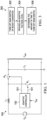
- FIG. 1 shows a top-level block diagram illustrating a DC-to-DC boost converter 100 in accordance with various embodiments.
- the boost converter 100 includes an input voltage source V in , an inductor L1, an output voltage node V out , an output capacitor C1, an adaptive controller 102, and two switches M1 and M2. More specifically, the adaptive controller 102 is configured to receive a feedback signal (e.g., V fb ) from the output voltage node V out , and based on the feedback signal (e.g., a current and/or voltage signal), the adaptive controller 102 provides a PWM signal 101 to alternately switch on and off the switches M1 and M2.
- a feedback signal e.g., V fb
- the switch M1 is referred to as the low-side switch
- the switch M2 is referred to as the high-side switch that operates time-exclusively with the low-side switch M1.
- the switch M1 while the switch M1 is on, the switch M2 is generally off, and vice versa-the switches are not both on at the same time.
- the low-side switch M1 While the low-side switch M1 is on, the input voltage source V in , the inductor L1, and the switch M1 forms a short circuit. Thus, energy starts to store inside the inductor L1 and current flowing through the inductor L1 increases. While the switch M1 is off, the energy stored inside the inductor L1 starts to discharge and the current flows through the inductor L1 to a load (e.g., the output capacitance C1) of the boost converter 100, resulting in a decrease of the inductor current.
- a load e.g., the output capacitance C1
- the adaptive controller 102 includes a circuit to tune a speed to turn on and off (i.e., varying the Miller time) with respect to the current flowing through the inductor L1 so as to actually turn off the switch M1 in a shorter period of time.
- the amount of time to turn off the switch M1 may be inversely proportional to the load current (i.e., the current flowing through the inductor L1), that is, the lower the load current the longer the amount of time to turn off the switch M1.
- the boost converter 100 may be subject to an efficiency issue while the switch M1 transitions from on to off.
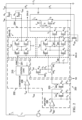
- FIG. 2 shows an exemplary circuitry 200 of the boost converter 100 in accordance with various embodiments.
- the adaptive controller 102 further includes two blocks 202 and 204. More particularly, block 202 is configured to receive the feedback signal V fb from the output voltage node V out , and based on the feedback signal, provide the PWM signal 201 to further control the switches M1 and M2, and to provide adaptive current i adp 203 that is proportional to the inductor current to block 204. Based on the adaptive current 203, block 204, which is coupled to block 202, is configured to provide an adaptive voltage node V adp , which is useful to control the speed (i.e., Miller time) for turning off the switch M1.
- the circuitry 200 further includes a sense controller, MS, coupled to the high-side switch M2.
- the sense controller MS is configured to sense a voltage/current level (e.g., V sns ) at a common node V sw connected to the high-side switch M1 and low-side switch M2.
- the boost converter 100 further includes a voltage divider (i.e., R0 and R1) that is used to divide the voltage level at the output voltage node V out and cause the feedback signal V fb to equal the divided signal. That is, V fb is less than the voltage level at the output voltage node V out and based on a voltage divider ratio of the resistors (e.g., R1/(R0+R1)
- the feedback signal V fb equals the voltage level at the output voltage node V out .
- block 202 further includes an error amplifier 206, a comparator 208, and a control logic 210.
- the error amplifier 206 includes two input terminals configured to receive signals form V fb and a reference voltage V ref respectively. Together with a capacitor C0 coupled to the output of the error amplifier, the error amplifier 206 is configured to provide the adaptive current i dap that is proportional to the inductor current. As shown in Figure 2 , the adaptive current is preferably to flow through each of the transistors M14 and M13.
- the comparator 208 is configured to compare V out and V sns so as to cause the coupled control logic 210 to produce a corresponding PWM signal that has a duty cycle to synchronously control a switching behavior of the switches M1 and M2.
- block 204 further includes a constant voltage node Vx, a sample- and-hold circuit (e.g., SW0 and SW1) coupled to the constant voltage node Vx, a high-side driver 204-HS coupled to the high-side switch M2, and a low-side driver 204-LS coupled to the low-side switch M1.
- the drivers 204-LS and 204-HS are configured to buffer the received PWM signal and increase a driving speed of the low-side and high-side switches respectively.
- M4 and serially connected M5 function as a first inverter of the high-side driver 204-HS
- M3 together with M6 functions as a second inverter connected in series with the first inverter.
- M7 and M9 forms a first inverter and M8 and M10 forms a second inverter connected in series with the first inverter.
- M1 ⁇ M10 are MOSFETs.
- the low-side driver 204-LS may further include a MOSFET M10A that is coupled to the M10. As shown in Figure 2 , a gate terminal of the M10A is connected to a voltage node V1, wherein the voltage node V1 is connected to a gate terminal of the low-side switch M1.
- the low-side driver 204-LS further includes an adaptive driving circuit coupled to the first and second inverters, wherein the adaptive driving circuit includes two transistors M11 and M12 and the switch M1. As shown in the circuitry 200, a drain terminal of the transistor M11 is connected to a gate terminal of the switch M1, and a gate terminal of the transistor M11 is coupled to the output voltage node V out via the transistor M8.
- the transistor M12 is connected serially to a source terminal of the transistor M11, and a gate terminal of the transistor M12 is connected to the adaptive voltage node V adp .
- i L i D + i G
- how fast i.e., the speed for the switch M1 to be off
- the current through M1 goes to zero may largely depends on a variation of i G , wherein i G is discharging current flowing through the parasitic capacitance C gd of the switch M1 to the serially connected transistor M11 and M12.
- Transistors M11 and M12 preferably operate in the linear region of a MOSFET. Further, the discharging current i G may be derived as, V g_M1 / (R on_M11 + R on_M12 ) , where V gs_M1 , R on_M11 , R on_M12 respectively represent a voltage drop across the gate and source terminals of the switch M1, a conductive resistance for the transistors M11 and M12. During switching off of the switch M1, V gs_M1 equals V th + K i L , wherein V th is a threshold voltage of the switch M1 and K is a proportional constant.
- the gate terminal of transistor M11 is coupled to the output voltage node V out that is approximately constant, resulting in an approximately constant value of the conductive resistance R on_M11 .
- the gate terminal of transistor M12 is coupled to the adaptive voltage node V adp that changes in accordance with the inductor current i L , and thus the conductive resistance R on_M12 may be derived as K 1 V adp ⁇ V th .
- M10 and M10A may increase a speed to discharge i L , especially when a voltage level at the voltage node V 1 is higher than the voltage level at the gate terminal of the low-side switch M1 to cause the switch M1 to operate in a saturation mode. More specifically, with decreasing the voltage level at the gate terminal of the switch M1, M1 and M10A will switch from linear region to saturation region, , meanwhile M12 may take over the function to discharge the inductor current i L .
- the variation of the speed varying with the inductor current may be optimized. Also, the amount of time to switch off the switch M1 may be reduced by the optimized value of resistance R4.
- the voltage level at the adaptive voltage node V adp is determined in accordance with the inductor current i L . Based on the equation, Vgs_M 1 / ( Ron_M 11 + Ron_M12) , described above, the speed and the variation of the speed may be may be optimally tuned by the user for a suitable application.
- SW0 and SW1 are configured to simultaneously switch on and off so as to sample a voltage level and hold the sampled voltage level to produce the adaptive voltage, V x - Ki L R 4 . More specifically, when the switches are on, SW0 and SW1 are coupled to the constant voltage node V x . When the switches are off, SW0 and SW1 are coupled to the adaptive voltage node V adp . To integrate the switches SW0 and SW1 with capacitor C1, an undesired DC current consumption while the switch M1 is off may be avoided.
- FIG. 3 shows a flow chart 300 to determine the amount of time to switch off the switch M1 of the boost converter 100 in accordance with various embodiments.
- the flow chart 300 starts in block 302 with turning off the main switch (i.e., the low-side switch M1) of the boost converter 100.
- turning off the main switch may be controlled by the PWM signal provided by the adaptive controller 102.
- the switch M1 While the switch M1 is being turned off, the inductor current flows through the switch M1 and the coupled low-side driver 204-LS to ground, wherein the coupled low-side driver 204-LS preferably functions as a discharging path for the current i G .
- the flow chart 300 continues in block 304 with providing the voltage level at the adaptive voltage node, V adp , to be inversely proportional to the inductor current.
- the adaptive voltage node is preferably coupled to the gate of the transistor of the low-side driver 204-LS.
- the conductive resistance of the transistor M12 which is preferably one of the parameters to determine the amount of time to switch off the main switch M1, varies with the inductor current as well.
- the amount of time to switch off the main switch M1 is determined by maintaining the gate terminal of the transistor M11 as the voltage level at the output voltage node V out .
- the conductive resistance of the transistor M11 changes very little if at all with the inductor current.
- the amount of time to switch off the main switch M1 majorly depends on how fast the current I G goes to zero (i.e., how much the current I G goes through the discharging path including the transistors M11 and M12). More specifically, a characteristic (e.g., conductive resistance) of the transistor (e.g., M12) changes with the voltage level at the adaptive voltage node.
- providing the adaptive voltage node to change its voltage level in accordance with the inductor current may advantageously determine the speed to switch off the main switch M1.
Landscapes
- Engineering & Computer Science (AREA)
- Power Engineering (AREA)
- Dc-Dc Converters (AREA)
Priority Applications (1)
| Application Number | Priority Date | Filing Date | Title |
|---|---|---|---|
| EP22203341.7A EP4191857B1 (en) | 2014-10-24 | 2014-10-24 | Adaptive controller for a voltage converter |
Applications Claiming Priority (3)
| Application Number | Priority Date | Filing Date | Title |
|---|---|---|---|
| EP22203341.7A EP4191857B1 (en) | 2014-10-24 | 2014-10-24 | Adaptive controller for a voltage converter |
| PCT/CN2014/089451 WO2016061815A1 (en) | 2014-10-24 | 2014-10-24 | Adaptive controller for voltage converter |
| EP14904536.1A EP3224937A4 (en) | 2014-10-24 | 2014-10-24 | ADAPTIVE CONTROL DEVICE FOR VOLTAGE CONVERTERS |
Related Parent Applications (1)
| Application Number | Title | Priority Date | Filing Date |
|---|---|---|---|
| EP14904536.1A Division EP3224937A4 (en) | 2014-10-24 | 2014-10-24 | ADAPTIVE CONTROL DEVICE FOR VOLTAGE CONVERTERS |
Publications (2)
| Publication Number | Publication Date |
|---|---|
| EP4191857A1 EP4191857A1 (en) | 2023-06-07 |
| EP4191857B1 true EP4191857B1 (en) | 2025-04-02 |
Family
ID=55760098
Family Applications (2)
| Application Number | Title | Priority Date | Filing Date |
|---|---|---|---|
| EP22203341.7A Active EP4191857B1 (en) | 2014-10-24 | 2014-10-24 | Adaptive controller for a voltage converter |
| EP14904536.1A Ceased EP3224937A4 (en) | 2014-10-24 | 2014-10-24 | ADAPTIVE CONTROL DEVICE FOR VOLTAGE CONVERTERS |
Family Applications After (1)
| Application Number | Title | Priority Date | Filing Date |
|---|---|---|---|
| EP14904536.1A Ceased EP3224937A4 (en) | 2014-10-24 | 2014-10-24 | ADAPTIVE CONTROL DEVICE FOR VOLTAGE CONVERTERS |
Country Status (5)
| Country | Link |
|---|---|
| US (2) | US9660528B2 (enExample) |
| EP (2) | EP4191857B1 (enExample) |
| JP (1) | JP6652561B2 (enExample) |
| CN (1) | CN107005157B (enExample) |
| WO (1) | WO2016061815A1 (enExample) |
Families Citing this family (4)
| Publication number | Priority date | Publication date | Assignee | Title |
|---|---|---|---|---|
| EP4191857B1 (en) | 2014-10-24 | 2025-04-02 | Texas Instruments Incorporated | Adaptive controller for a voltage converter |
| EP3987640B1 (en) * | 2019-06-24 | 2025-08-13 | Texas Instruments Incorporated | Switching converter with multiple drive stages and related modes |
| KR102910469B1 (ko) | 2020-01-09 | 2026-01-09 | 삼성디스플레이 주식회사 | 표시 장치 |
| CN112751485B (zh) * | 2020-12-31 | 2022-04-22 | 上海艾为电子技术股份有限公司 | 一种升压电路及电子设备 |
Family Cites Families (35)
| Publication number | Priority date | Publication date | Assignee | Title |
|---|---|---|---|---|
| DE19848829C2 (de) * | 1998-10-22 | 2002-10-10 | Infineon Technologies Ag | Schaltungsanordnung zur Einstellung der Abschaltflanke eines Laststromes |
| DE10032846A1 (de) * | 1999-07-12 | 2001-01-25 | Int Rectifier Corp | Leistungsfaktor-Korrektursteuerschaltung |
| US6690144B1 (en) * | 2002-08-09 | 2004-02-10 | Motorola, Inc. | Open loop inductor current control system and method |
| US6768655B1 (en) * | 2003-02-03 | 2004-07-27 | System General Corp. | Discontinuous mode PFC controller having a power saving modulator and operation method thereof |
| JP4144541B2 (ja) * | 2004-03-19 | 2008-09-03 | 日産自動車株式会社 | 電圧駆動型半導体素子用駆動回路 |
| US7812576B2 (en) * | 2004-09-24 | 2010-10-12 | Marvell World Trade Ltd. | Power factor control systems and methods |
| CN100403632C (zh) * | 2005-04-15 | 2008-07-16 | 矽创电子股份有限公司 | 快速回复的低压降线性稳压器 |
| CN101071981B (zh) * | 2006-05-11 | 2010-09-29 | 中华映管股份有限公司 | 升压式直流/直流转换器 |
| US7812647B2 (en) * | 2007-05-21 | 2010-10-12 | Advanced Analogic Technologies, Inc. | MOSFET gate drive with reduced power loss |
| KR101030798B1 (ko) * | 2007-08-22 | 2011-04-27 | 주식회사 실리콘마이터스 | 역률 보상 회로 |
| JP5167733B2 (ja) * | 2007-09-06 | 2013-03-21 | 株式会社リコー | 昇圧型dc/dcコンバータ |
| TWI374605B (en) * | 2008-08-21 | 2012-10-11 | Leadtrend Tech Corp | Apparatus and method for zero-voltage region detection, and control apparatus and control method for a power factor correction power converter |
| WO2010030741A1 (en) * | 2008-09-11 | 2010-03-18 | Marvell Semiconductor, Inc. | Intelligent switching controller and power conversion circuits and methods |
| CN102187560B (zh) * | 2008-11-25 | 2013-12-11 | 株式会社村田制作所 | Pfc变换器 |
| CN101459381B (zh) * | 2008-12-10 | 2010-08-11 | 浙江大学 | 一种Boost型开关变换器的控制装置及控制方法 |
| US8116045B2 (en) * | 2009-01-23 | 2012-02-14 | Linear Technology Corporation | Circuitry and methodology for protecting a boost DC/DC converter |
| WO2010131496A1 (ja) * | 2009-05-15 | 2010-11-18 | 株式会社村田製作所 | Pfcコンバータ |
| US8368361B2 (en) * | 2009-09-30 | 2013-02-05 | Cirrus Logic, Inc. | Switching power converter controller with direct current transformer sensing |
| JP5513829B2 (ja) * | 2009-10-01 | 2014-06-04 | パナソニック株式会社 | 電流駆動回路 |
| JP5341781B2 (ja) * | 2010-01-04 | 2013-11-13 | ルネサスエレクトロニクス株式会社 | 電力供給制御回路 |
| JP5341780B2 (ja) * | 2010-01-04 | 2013-11-13 | ルネサスエレクトロニクス株式会社 | 電力供給制御回路 |
| US8773111B2 (en) * | 2010-02-25 | 2014-07-08 | Fuji Electric Co., Ltd. | Current estimation circuit |
| TWI399926B (zh) * | 2010-05-17 | 2013-06-21 | Richtek Technology Corp | 適應性同步時脈移相產生電路及同步時脈移相產生方法 |
| CN101931323B (zh) * | 2010-08-05 | 2012-11-28 | 西安交通大学 | 一种提高集成开关dc-dc变换器轻载效率非均匀变化栅宽的方法 |
| CN101937014B (zh) * | 2010-08-05 | 2012-10-17 | 复旦大学 | 一种适用于宽转换比升压变换器的自适应电流检测电路 |
| JP2012147084A (ja) * | 2011-01-07 | 2012-08-02 | Denso Corp | 出力回路 |
| JP5270713B2 (ja) * | 2011-04-19 | 2013-08-21 | シャープ株式会社 | スイッチング電源装置 |
| CN102290991B (zh) * | 2011-05-27 | 2013-09-18 | 武汉大学 | 一种电流模式的dc-dc变换器的频率补偿装置 |
| JP2012253953A (ja) * | 2011-06-06 | 2012-12-20 | Mitsumi Electric Co Ltd | 昇圧型dc−dcコンバータ |
| JP5704124B2 (ja) * | 2012-06-14 | 2015-04-22 | 株式会社村田製作所 | スイッチング電源装置 |
| CN103684378B (zh) * | 2012-08-29 | 2017-05-24 | 英飞凌科技奥地利有限公司 | 用于驱动晶体管的电路 |
| US9124231B2 (en) * | 2013-01-28 | 2015-09-01 | Qualcomm, Inc. | Soft turn-off for boost converters |
| JP5700145B2 (ja) * | 2014-02-07 | 2015-04-15 | 富士電機株式会社 | 絶縁ゲート型デバイスの駆動回路 |
| US9647541B2 (en) * | 2014-09-04 | 2017-05-09 | Texas Instruments Incorporated | Hysteretic control DC/DC converter switching frequency with reduced dependence on voltage and current |
| EP4191857B1 (en) * | 2014-10-24 | 2025-04-02 | Texas Instruments Incorporated | Adaptive controller for a voltage converter |
-
2014
- 2014-10-24 EP EP22203341.7A patent/EP4191857B1/en active Active
- 2014-10-24 WO PCT/CN2014/089451 patent/WO2016061815A1/en not_active Ceased
- 2014-10-24 EP EP14904536.1A patent/EP3224937A4/en not_active Ceased
- 2014-10-24 JP JP2017522402A patent/JP6652561B2/ja active Active
- 2014-10-24 CN CN201480082683.8A patent/CN107005157B/zh active Active
-
2015
- 2015-02-25 US US14/631,178 patent/US9660528B2/en active Active
-
2017
- 2017-04-20 US US15/492,884 patent/US10020733B2/en active Active
Also Published As
| Publication number | Publication date |
|---|---|
| US20160118889A1 (en) | 2016-04-28 |
| EP3224937A4 (en) | 2019-01-09 |
| CN107005157A (zh) | 2017-08-01 |
| US9660528B2 (en) | 2017-05-23 |
| EP4191857A1 (en) | 2023-06-07 |
| JP6652561B2 (ja) | 2020-02-26 |
| CN107005157B (zh) | 2019-06-14 |
| US10020733B2 (en) | 2018-07-10 |
| WO2016061815A1 (en) | 2016-04-28 |
| EP3224937A1 (en) | 2017-10-04 |
| US20170324327A1 (en) | 2017-11-09 |
| JP2017532945A (ja) | 2017-11-02 |
Similar Documents
| Publication | Publication Date | Title |
|---|---|---|
| US7868599B2 (en) | Method of optimum current blanking time implementation in current sense circuit | |
| US7138786B2 (en) | Power supply driver circuit | |
| KR101804401B1 (ko) | 고전압 스위칭 레귤레이터들을 위한 효율적인 전류 센싱 | |
| US7675275B2 (en) | DC-DC converter | |
| US8310219B2 (en) | DC-DC converter with a PWM mode and a continuously on mode | |
| US9768687B2 (en) | Step-down DC/DC converter | |
| US10044263B2 (en) | Using PMOS power switch in a combination switching and linear regulator | |
| US9685865B2 (en) | Power-supply apparatus having a high-side transistor and a low-side transistor | |
| US7113412B2 (en) | Drive circuit and power supply apparatus | |
| US9584115B2 (en) | Duty cycle-controlled load switch | |
| US9729060B2 (en) | Power conversion apparatus having DC-DC converters with different gate resistances | |
| US8058860B2 (en) | Single pin multi-VID bit interface circuit for dynamic voltage change of a DC/DC converter | |
| US10784775B1 (en) | Switching converter with reduced dead-time | |
| US10020733B2 (en) | Adaptive controller for a voltage converter | |
| JP2022135911A (ja) | バイポーラパルス電圧ゲートドライバ | |
| CN111464029B (zh) | 用于dc-dc转换器的电流感测控制器 | |
| US20190068173A1 (en) | Method for driving a transistor device with non-isolated gate, drive circuit and electronic circuit | |
| JP5176871B2 (ja) | ドライバ回路およびdc−dcコンバータ | |
| US11641162B2 (en) | Circuits and methods for generating a supply voltage for a switching regulator | |
| JP6919920B2 (ja) | 電圧コンバータのためのアダプティブコントローラ | |
| US20260025059A1 (en) | Gate driver circuit, power supply control circuit, and power supply device | |
| US20040257051A1 (en) | DC-DC converter | |
| JPH07312865A (ja) | 部分共振型スイッチング電源回路 |
Legal Events
| Date | Code | Title | Description |
|---|---|---|---|
| PUAI | Public reference made under article 153(3) epc to a published international application that has entered the european phase |
Free format text: ORIGINAL CODE: 0009012 |
|
| STAA | Information on the status of an ep patent application or granted ep patent |
Free format text: STATUS: THE APPLICATION HAS BEEN PUBLISHED |
|
| AC | Divisional application: reference to earlier application |
Ref document number: 3224937 Country of ref document: EP Kind code of ref document: P |
|
| AK | Designated contracting states |
Kind code of ref document: A1 Designated state(s): AL AT BE BG CH CY CZ DE DK EE ES FI FR GB GR HR HU IE IS IT LI LT LU LV MC MK MT NL NO PL PT RO RS SE SI SK SM TR |
|
| STAA | Information on the status of an ep patent application or granted ep patent |
Free format text: STATUS: REQUEST FOR EXAMINATION WAS MADE |
|
| 17P | Request for examination filed |
Effective date: 20231207 |
|
| RBV | Designated contracting states (corrected) |
Designated state(s): AL AT BE BG CH CY CZ DE DK EE ES FI FR GB GR HR HU IE IS IT LI LT LU LV MC MK MT NL NO PL PT RO RS SE SI SK SM TR |
|
| STAA | Information on the status of an ep patent application or granted ep patent |
Free format text: STATUS: EXAMINATION IS IN PROGRESS |
|
| 17Q | First examination report despatched |
Effective date: 20240305 |
|
| RIC1 | Information provided on ipc code assigned before grant |
Ipc: H02M 1/00 20060101ALN20240925BHEP Ipc: H02M 3/158 20060101ALI20240925BHEP Ipc: H03K 17/16 20060101ALI20240925BHEP Ipc: H03K 17/14 20060101ALI20240925BHEP Ipc: H03K 17/042 20060101ALI20240925BHEP Ipc: H02M 1/08 20060101ALI20240925BHEP Ipc: H02M 3/07 20060101AFI20240925BHEP |
|
| RIC1 | Information provided on ipc code assigned before grant |
Ipc: H02M 1/00 20060101ALN20241002BHEP Ipc: H02M 3/158 20060101ALI20241002BHEP Ipc: H03K 17/16 20060101ALI20241002BHEP Ipc: H03K 17/14 20060101ALI20241002BHEP Ipc: H03K 17/042 20060101ALI20241002BHEP Ipc: H02M 1/08 20060101ALI20241002BHEP Ipc: H02M 3/07 20060101AFI20241002BHEP |
|
| GRAP | Despatch of communication of intention to grant a patent |
Free format text: ORIGINAL CODE: EPIDOSNIGR1 |
|
| STAA | Information on the status of an ep patent application or granted ep patent |
Free format text: STATUS: GRANT OF PATENT IS INTENDED |
|
| RIC1 | Information provided on ipc code assigned before grant |
Ipc: H02M 1/00 20060101ALN20241105BHEP Ipc: H02M 3/158 20060101ALI20241105BHEP Ipc: H03K 17/16 20060101ALI20241105BHEP Ipc: H03K 17/14 20060101ALI20241105BHEP Ipc: H03K 17/042 20060101ALI20241105BHEP Ipc: H02M 1/08 20060101ALI20241105BHEP Ipc: H02M 3/07 20060101AFI20241105BHEP |
|
| INTG | Intention to grant announced |
Effective date: 20241119 |
|
| P01 | Opt-out of the competence of the unified patent court (upc) registered |
Free format text: CASE NUMBER: APP_2102/2025 Effective date: 20250113 |
|
| GRAS | Grant fee paid |
Free format text: ORIGINAL CODE: EPIDOSNIGR3 |
|
| GRAA | (expected) grant |
Free format text: ORIGINAL CODE: 0009210 |
|
| STAA | Information on the status of an ep patent application or granted ep patent |
Free format text: STATUS: THE PATENT HAS BEEN GRANTED |
|
| AC | Divisional application: reference to earlier application |
Ref document number: 3224937 Country of ref document: EP Kind code of ref document: P |
|
| AK | Designated contracting states |
Kind code of ref document: B1 Designated state(s): AL AT BE BG CH CY CZ DE DK EE ES FI FR GB GR HR HU IE IS IT LI LT LU LV MC MK MT NL NO PL PT RO RS SE SI SK SM TR |
|
| REG | Reference to a national code |
Ref country code: GB Ref legal event code: FG4D |
|
| REG | Reference to a national code |
Ref country code: CH Ref legal event code: EP |
|
| REG | Reference to a national code |
Ref country code: DE Ref legal event code: R096 Ref document number: 602014091779 Country of ref document: DE |
|
| REG | Reference to a national code |
Ref country code: IE Ref legal event code: FG4D |
|
| REG | Reference to a national code |
Ref country code: NL Ref legal event code: MP Effective date: 20250402 |
|
| PG25 | Lapsed in a contracting state [announced via postgrant information from national office to epo] |
Ref country code: NL Free format text: LAPSE BECAUSE OF FAILURE TO SUBMIT A TRANSLATION OF THE DESCRIPTION OR TO PAY THE FEE WITHIN THE PRESCRIBED TIME-LIMIT Effective date: 20250402 |
|
| REG | Reference to a national code |
Ref country code: AT Ref legal event code: MK05 Ref document number: 1782299 Country of ref document: AT Kind code of ref document: T Effective date: 20250402 |
|
| PG25 | Lapsed in a contracting state [announced via postgrant information from national office to epo] |
Ref country code: FI Free format text: LAPSE BECAUSE OF FAILURE TO SUBMIT A TRANSLATION OF THE DESCRIPTION OR TO PAY THE FEE WITHIN THE PRESCRIBED TIME-LIMIT Effective date: 20250402 Ref country code: ES Free format text: LAPSE BECAUSE OF FAILURE TO SUBMIT A TRANSLATION OF THE DESCRIPTION OR TO PAY THE FEE WITHIN THE PRESCRIBED TIME-LIMIT Effective date: 20250402 Ref country code: PT Free format text: LAPSE BECAUSE OF FAILURE TO SUBMIT A TRANSLATION OF THE DESCRIPTION OR TO PAY THE FEE WITHIN THE PRESCRIBED TIME-LIMIT Effective date: 20250804 |
|
| REG | Reference to a national code |
Ref country code: LT Ref legal event code: MG9D |
|
| PG25 | Lapsed in a contracting state [announced via postgrant information from national office to epo] |
Ref country code: GR Free format text: LAPSE BECAUSE OF FAILURE TO SUBMIT A TRANSLATION OF THE DESCRIPTION OR TO PAY THE FEE WITHIN THE PRESCRIBED TIME-LIMIT Effective date: 20250703 Ref country code: NO Free format text: LAPSE BECAUSE OF FAILURE TO SUBMIT A TRANSLATION OF THE DESCRIPTION OR TO PAY THE FEE WITHIN THE PRESCRIBED TIME-LIMIT Effective date: 20250702 |
|
| PG25 | Lapsed in a contracting state [announced via postgrant information from national office to epo] |
Ref country code: PL Free format text: LAPSE BECAUSE OF FAILURE TO SUBMIT A TRANSLATION OF THE DESCRIPTION OR TO PAY THE FEE WITHIN THE PRESCRIBED TIME-LIMIT Effective date: 20250402 |
|
| PG25 | Lapsed in a contracting state [announced via postgrant information from national office to epo] |
Ref country code: BG Free format text: LAPSE BECAUSE OF FAILURE TO SUBMIT A TRANSLATION OF THE DESCRIPTION OR TO PAY THE FEE WITHIN THE PRESCRIBED TIME-LIMIT Effective date: 20250402 |
|
| PGFP | Annual fee paid to national office [announced via postgrant information from national office to epo] |
Ref country code: GB Payment date: 20250923 Year of fee payment: 12 |
|
| PG25 | Lapsed in a contracting state [announced via postgrant information from national office to epo] |
Ref country code: HR Free format text: LAPSE BECAUSE OF FAILURE TO SUBMIT A TRANSLATION OF THE DESCRIPTION OR TO PAY THE FEE WITHIN THE PRESCRIBED TIME-LIMIT Effective date: 20250402 |
|
| PG25 | Lapsed in a contracting state [announced via postgrant information from national office to epo] |
Ref country code: AT Free format text: LAPSE BECAUSE OF FAILURE TO SUBMIT A TRANSLATION OF THE DESCRIPTION OR TO PAY THE FEE WITHIN THE PRESCRIBED TIME-LIMIT Effective date: 20250402 |
|
| PGFP | Annual fee paid to national office [announced via postgrant information from national office to epo] |
Ref country code: FR Payment date: 20250924 Year of fee payment: 12 |
|
| PG25 | Lapsed in a contracting state [announced via postgrant information from national office to epo] |
Ref country code: RS Free format text: LAPSE BECAUSE OF FAILURE TO SUBMIT A TRANSLATION OF THE DESCRIPTION OR TO PAY THE FEE WITHIN THE PRESCRIBED TIME-LIMIT Effective date: 20250702 |
|
| PG25 | Lapsed in a contracting state [announced via postgrant information from national office to epo] |
Ref country code: IS Free format text: LAPSE BECAUSE OF FAILURE TO SUBMIT A TRANSLATION OF THE DESCRIPTION OR TO PAY THE FEE WITHIN THE PRESCRIBED TIME-LIMIT Effective date: 20250802 |
|
| PG25 | Lapsed in a contracting state [announced via postgrant information from national office to epo] |
Ref country code: LV Free format text: LAPSE BECAUSE OF FAILURE TO SUBMIT A TRANSLATION OF THE DESCRIPTION OR TO PAY THE FEE WITHIN THE PRESCRIBED TIME-LIMIT Effective date: 20250402 |
|
| REG | Reference to a national code |
Ref country code: DE Ref legal event code: R097 Ref document number: 602014091779 Country of ref document: DE |
|
| PGFP | Annual fee paid to national office [announced via postgrant information from national office to epo] |
Ref country code: DE Payment date: 20250923 Year of fee payment: 12 |
|
| PG25 | Lapsed in a contracting state [announced via postgrant information from national office to epo] |
Ref country code: SM Free format text: LAPSE BECAUSE OF FAILURE TO SUBMIT A TRANSLATION OF THE DESCRIPTION OR TO PAY THE FEE WITHIN THE PRESCRIBED TIME-LIMIT Effective date: 20250402 Ref country code: DK Free format text: LAPSE BECAUSE OF FAILURE TO SUBMIT A TRANSLATION OF THE DESCRIPTION OR TO PAY THE FEE WITHIN THE PRESCRIBED TIME-LIMIT Effective date: 20250402 |
|
| PG25 | Lapsed in a contracting state [announced via postgrant information from national office to epo] |
Ref country code: CZ Free format text: LAPSE BECAUSE OF FAILURE TO SUBMIT A TRANSLATION OF THE DESCRIPTION OR TO PAY THE FEE WITHIN THE PRESCRIBED TIME-LIMIT Effective date: 20250402 |
|
| PG25 | Lapsed in a contracting state [announced via postgrant information from national office to epo] |
Ref country code: EE Free format text: LAPSE BECAUSE OF FAILURE TO SUBMIT A TRANSLATION OF THE DESCRIPTION OR TO PAY THE FEE WITHIN THE PRESCRIBED TIME-LIMIT Effective date: 20250402 |
|
| PG25 | Lapsed in a contracting state [announced via postgrant information from national office to epo] |
Ref country code: SK Free format text: LAPSE BECAUSE OF FAILURE TO SUBMIT A TRANSLATION OF THE DESCRIPTION OR TO PAY THE FEE WITHIN THE PRESCRIBED TIME-LIMIT Effective date: 20250402 |
|
| PG25 | Lapsed in a contracting state [announced via postgrant information from national office to epo] |
Ref country code: IT Free format text: LAPSE BECAUSE OF FAILURE TO SUBMIT A TRANSLATION OF THE DESCRIPTION OR TO PAY THE FEE WITHIN THE PRESCRIBED TIME-LIMIT Effective date: 20250402 |
|
| PLBE | No opposition filed within time limit |
Free format text: ORIGINAL CODE: 0009261 |
|
| STAA | Information on the status of an ep patent application or granted ep patent |
Free format text: STATUS: NO OPPOSITION FILED WITHIN TIME LIMIT |
|
| REG | Reference to a national code |
Ref country code: CH Ref legal event code: L10 Free format text: ST27 STATUS EVENT CODE: U-0-0-L10-L00 (AS PROVIDED BY THE NATIONAL OFFICE) Effective date: 20260211 |
|
| PG25 | Lapsed in a contracting state [announced via postgrant information from national office to epo] |
Ref country code: RO Free format text: LAPSE BECAUSE OF FAILURE TO SUBMIT A TRANSLATION OF THE DESCRIPTION OR TO PAY THE FEE WITHIN THE PRESCRIBED TIME-LIMIT Effective date: 20250402 |
|
| 26N | No opposition filed |
Effective date: 20260105 |