EP4191847A1 - Transducteur electromagnetique pour la recuperation d'energie vibratoire - Google Patents
Transducteur electromagnetique pour la recuperation d'energie vibratoire Download PDFInfo
- Publication number
- EP4191847A1 EP4191847A1 EP22210756.7A EP22210756A EP4191847A1 EP 4191847 A1 EP4191847 A1 EP 4191847A1 EP 22210756 A EP22210756 A EP 22210756A EP 4191847 A1 EP4191847 A1 EP 4191847A1
- Authority
- EP
- European Patent Office
- Prior art keywords
- magnet
- axis
- electromagnetic transducer
- coil
- central mass
- Prior art date
- Legal status (The legal status is an assumption and is not a legal conclusion. Google has not performed a legal analysis and makes no representation as to the accuracy of the status listed.)
- Pending
Links
Images


Classifications
-
- H—ELECTRICITY
- H02—GENERATION; CONVERSION OR DISTRIBUTION OF ELECTRIC POWER
- H02N—ELECTRIC MACHINES NOT OTHERWISE PROVIDED FOR
- H02N2/00—Electric machines in general using piezoelectric effect, electrostriction or magnetostriction
- H02N2/18—Electric machines in general using piezoelectric effect, electrostriction or magnetostriction producing electrical output from mechanical input, e.g. generators
- H02N2/186—Vibration harvesters
-
- H—ELECTRICITY
- H02—GENERATION; CONVERSION OR DISTRIBUTION OF ELECTRIC POWER
- H02K—DYNAMO-ELECTRIC MACHINES
- H02K1/00—Details of the magnetic circuit
- H02K1/06—Details of the magnetic circuit characterised by the shape, form or construction
- H02K1/34—Reciprocating, oscillating or vibrating parts of the magnetic circuit
-
- H—ELECTRICITY
- H02—GENERATION; CONVERSION OR DISTRIBUTION OF ELECTRIC POWER
- H02K—DYNAMO-ELECTRIC MACHINES
- H02K35/00—Generators with reciprocating, oscillating or vibrating coil system, magnet, armature or other part of the magnetic circuit
- H02K35/02—Generators with reciprocating, oscillating or vibrating coil system, magnet, armature or other part of the magnetic circuit with moving magnets and stationary coil systems
Definitions
- the present invention relates to an electromagnetic transducer for the recovery of vibrational energy.
- the invention relates to an electromagnetic transducer comprising a support, a central mass, and at least one spring connecting the central mass to the support, the spring allowing the movement of the central mass relative to the support along a first axis.
- the present invention also relates to a set of electromagnetic transducers.
- vibration energy harvesters The purpose of vibration energy harvesters is to electrically supply electronic systems from the vibrations present in their environment. These require less maintenance and generate less pollution than batteries and are particularly interesting when the system to be powered is located in an inaccessible place, deprived of light and sufficient thermal gradient.
- industrialization and marketing of these vibration energy harvesters is blocked by their still insufficient robustness. Indeed, although many recuperators are theoretically able to provide the power required by their application (supply of very low consumption electronic systems), they are often unable to adapt to the frequency fluctuations of real vibration sources.
- these vibratory energy collectors are used in environments subject to temperature changes, whereas these collectors are unsuitable for such variations.
- vibration energy harvesters have difficulty withstanding the aging of their constituent elements.
- This method consists in maximizing the transfer of power between the vibratory source and the electrical load, not only at resonance (when the frequency of the vibration coincides with the natural resonant frequency of the mechanical resonator) but also out of resonance, by means of an impedance matching circuit located at the electrical load. This results in an increase in the effective bandwidth of the recuperator, thus making the latter more robust to real conditions of use.
- the impact of the electrical adjustment on the bandwidth depends firstly on the type of transducer carrying out the energy conversion, the type of transducer determining the physical equations governing the behavior of the recuperator. In particular, there are piezoelectric transducers and electromagnetic transducers. Secondly, the electrical adjustment on the bandwidth depends on the characteristic parameters of the recuperator such as the mobile mass related to the total volume (effective density of the recuperator), the mechanical quality factor, the mechanical resonance frequency, and the coupling. We speak of piezoelectric coupling in the case of a piezoelectric transducer, and of electromagnetic coupling in the case of an electromagnetic transducer.
- the performance of electromagnetic recuperators is limited by the fact that, for a given displacement of the mobile, the variation in magnetic flux is often too small for the electrical adjustment method to significantly increase the effective bandwidth of the recuperator.
- the performance of the electrical adjustment strategy is therefore better for piezoelectric harvesters.
- electromagnetic recuperators have decisive advantages on other levels such as the technological maturity of manufacturing processes, cost, mechanical resistance to shocks and long-term use, etc. This is why the development of electromagnetic type recuperators remains relevant.
- the invention aims to overcome all or part of the problems cited above by proposing an electromagnetic transducer allowing strong coupling, significantly higher than the known electromagnetic recuperators, as well as a high effective density.
- the invention aims to achieve better performance in terms of bandwidth and power density with the electrical adjustment method.
- the electrical adjustment method is based on the theorem of maximizing power transfer between any source and any load.
- the transferred power is maximum when the impedance of the load is equal to the complex conjugate of the impedance of the source.
- figure 1 represents a generic model 10 describing the behavior of electromagnetic transduction recuperators 11 under the assumption of small displacements, associated with an impedance matching circuit 12.
- the recuperator delivering the voltage v and the current i, is assimilated to the source while that the matching circuit constitutes the load.
- Certain known devices are based on the relative displacement of a source of magnetic field with respect to a coil.
- the displacement, eg translation or rotation, of a magnetic field created by a magnet causes a variation of the magnetic flux in a coil.
- it is necessary to use a ferromagnetic guide integral with the magnet in order to channel the lines of the magnetic field at the place through which the coil passes, while reducing the air gap of the magnetic circuit to its strict minimum.
- This minimum air gap is the thickness of the coil (simply because if the air gap was thinner than the thickness of the coil, the latter could no longer pass through the assembly consisting of the ferromagnetic guide and the magnet).
- the coil on the other hand, must be adequately sized to maximize the derivative of the magnetic flux within it.
- a coil that is too thin leads to too weak a derivative of the magnetic flux even with the ferromagnetic guide. Consequently, a compromise must be found between the thickness of the air gap and that of the coil, and this compromise leads to an electromagnetic coupling significantly lower than the electromagnetic coupling achievable with transducers based on a variation of magnetic field (transducers for which the thickness of the air gap is independent of the thickness of the coil).
- recuperators based on the relative displacement of a magnetic source with respect to a coil have the advantage of not generating any magnetic force between the mobile and the base of the recuperator, this force being the cause of difficulties in modeling (complex analytical calculation, non-linearity), design and manufacturing. In particular, there are possibilities of sticking during the assembly or use phase, or the generation of dry friction, etc.
- recuperators are transducers based on a variation in the shape or intensity of the magnetic field created by the magnet. These are transducers for which the variation in magnetic flux in the winding is caused by a modification of the magnetic field created by the magnet by means of ferromagnetic elements moving relative to it. Moving a mobile causes a variation in the thickness of the air gaps, ie the distance separating the mobile from the rest of the ferromagnetic guide containing the magnets. This air gap variation leads to a variation in the reluctance of the magnetic circuit supplied by the magnets, so that the flux picked up by the coil is maximum when the mobile is in a position such that the air gap is low, and minimum in a position such that the air gap is high.
- such devices require special attention with regard to the magnetic force because this can cause sticking or dry friction if no provision is made during the design of the recuperator.
- the invention aims to overcome the problems cited above by proposing an electromagnetic transducer that is significantly less subject to sticking or dry friction and which is particularly compact.
- the subject of the invention is an electromagnetic transducer comprising a support, a central mass, and at least one spring connecting the central mass to the support, the spring allowing the movement of the central mass relative to the support along a first axis ;
- the central mass comprising a central ferromagnetic element, a first magnet, a second magnet, and two additional ferromagnetic elements, the ferromagnetic element being flanked on a first side along the first axis by the first magnet and flanked on a second side, opposite the first side along the first axis, by the second magnet, the first magnet and the second magnet each being flanked along the first axis by one of the additional ferromagnetic elements;
- the support surrounding the central mass radially to the first axis and an air gap separating the support from the central mass, the support comprising at least one coil wound around the first axis and integral with an external ferromagnetic element; the electromagnetic transducer being configured such that the magnetic flux of the first magnet and the magnetic flux
- the spring allowing the displacement of the central mass relative to the support along a first axis
- the spring is capable of deforming in response to a vibration, its deformation causing a displacement of the central mass along a first axis.
- the support surrounding the central mass radially to the first axis and an air gap separating the support from the central mass it is understood that the support is arranged around and at a distance from the central mass. This distance is large enough for vibrations which would cause the movement of the central mass not to cause friction between the central mass and the support.
- This air gap or this distance essentially depends on the difference in stiffness between the radial magnetic force tending to move the mass away from its axis of translation, and the radial mechanical force linked to the springs tending to compensate for the magnetic stiffness and bring the mass back to its axis of translation. translation.
- the air gap is a function of the dimensions of the central mass and must be assessed according to the technical tolerance margin of its manufacturing method and according to a thermal expansion tolerance according to the environment of use.
- a coil wound around the axis it is understood that the coil is arranged radially to the first axis.
- the magnetic flux of the first magnet and the magnetic flux of the second magnet each follow a path
- the spatial distribution of the magnetic field and in particular the majority of the lines of the magnetic field are guided along a specific path.
- the first path not crossing the coil and “the second path crossing the coil and continuing around the coil” it is understood by “crossing the coil” that the lines of the magnetic field are guided so as to cross the radial plane in which the coil is arranged with respect to the first axis.
- crossing the coil it is understood that the lines of the magnetic field are guided to form a loop going from one pole to the other of the same magnet, the loop winding around the coil.
- the electromagnetic transducer of the present invention therefore combines (i) the relative displacement of a magnetic source, here the central mass comprising a first magnet and a second magnet, with respect to a coil, here the support comprising the wound coil and (ii ) a variation of the magnetic field created by the magnets of the central mass according to the ferromagnetic elements which are in motion (ferromagnetic elements included in the central mass) or not (ferromagnetic elements included in the support).
- the electromagnetic transducer of the present invention includes a minimized air gap, the air gap being only large enough to separate the support from the central mass and allow movement of the central mass relative to the support.
- the coil is located on the support which when using the electromagnetic transducer is fixed.
- the electromagnetic transducer of the present invention is adapted so that the central mass occupies a maximum volume in the electromagnetic transducer, which makes it possible to maximize the effective density and the electromagnetic coupling.
- the electromagnetic transducer of the present invention can be made using magnets of standard shape and magnetization, reducing manufacturing or assembly costs as well as potential maintenance costs.
- the electromagnetic transducer allows movement of the central mass which is limited only along the first axis and by the spring, no other element included in the electromagnetic transducer limiting the stroke of the central mass.
- the dimensioning of the electromagnetic transducer of the present invention is simple and independent of the displacement of the central mass.
- the spring of the electromagnetic transducer of the invention comprises a first spring fixed to an external face of one of the additional ferromagnetic elements and a second spring fixed to an external face of the other additional ferromagnetic element.
- the spring of the electromagnetic transducer of the invention comprises at least one flat spring extending mainly in a plane perpendicular to the first axis, preferably being a three-branch spiral spring.
- the coil of the electromagnetic transducer of the invention is entirely embedded in the external ferromagnetic element.
- the central mass of the electromagnetic transducer of the invention is flanked on at least one side along the first axis by a third magnet and an additional ferromagnetic element.
- the support of the electromagnetic transducer of the invention comprises several coils.
- the axes of the poles of the first and of the second magnet of the electromagnetic transducer of the invention are reversed along the first axis.
- the central mass of the electromagnetic transducer of the invention is cylindrical.
- the electromagnetic transducer of the invention further comprises protection of the coil.
- the invention also relates to a set of electromagnetic transducers as described previously, the coils of the electromagnetic transducers being connected together in parallel and/or in series.
- the electromagnetic transducer of the present invention has an essentially axisymmetric structure that can be contained in a simple volume such as a cylinder. This makes it possible in particular to minimize the edge effects of the magnetic field, to minimize the volume lost by its packaging and to facilitate its integration into a generic context. Furthermore, the essentially axisymmetric structure of the electromagnetic transducer of the present invention makes it possible to accelerate the convergence of the FEM simulations necessary for its dimensioning.
- the electromagnetic transducer 20 comprises a central ferromagnetic element 25 flanked on a first side along the first axis 27 by a first magnet 21 having a face 21a facing the central ferromagnetic element 25 and an opposite face 21b.
- This first magnet 21 is flanked along the first axis 27 and facing its opposite face 21b by an additional ferromagnetic element 23.
- the ferromagnetic element 25 is flanked on a second side along the first axis 27 and opposite the first side by a second magnet 22 having a face 22a opposite the central ferromagnetic element 25 and an opposite face 22b.
- This second magnet 22 is flanked along the first axis 27 and opposite its opposite face 22b by an additional ferromagnetic element 24.
- the first magnet and the second magnet are arranged so that the opposite faces along the first axis each constitute a pole, that is to say that the face 21a corresponds to the north or south pole while the face 21b corresponds to the opposite pole, the same for the faces 22a and 22b.
- the elements forming the central mass that is to say the central ferromagnetic element 25, the first magnet 21, the second magnet 22 and the additional ferromagnetic elements 23, 24 are cylinders, preferably cylinders of revolution .
- the electromagnetic transducer 20 also comprises a support 30 surrounding the central mass radially to the first axis and an air gap separating the support 30 from the central mass.
- the support 30 comprises a coil 31 wound around the first axis and secured to an external ferromagnetic element 32.
- the external ferromagnetic element 32 is in particular a single block. Indeed, when the outer ferromagnetic element 32 is in several parts, the presence of junctions between its parts can disturb the magnetic fluxes 28, 29.
- the coil 31 is enclosed at least partially in the outer ferromagnetic element 32, it that is to say that each of its faces is at least partially covered by a part of the outer ferromagnetic element 32, the latter must then be in several parts.
- the outer ferromagnetic element 32 may in particular comprise a housing open to the central mass 21 in which the coil 31 is inserted, as shown.
- the coil 31 may in particular be flush with the surface of the outer ferromagnetic element 32 or set back from the surface of the latter.
- the coil is sized to be set back from the surface of the latter, which limits the functional clearances.
- the housing is configured so that the coil 31 is arranged facing only the central ferromagnetic element 25 in the equilibrium position of the electromagnetic transducer 20, as shown.
- the height of the coil 31 is less than or equal to that of the central ferromagnetic element 25.
- the path of the magnetic fluxes 29, 29 of the magnets 21, 22 is therefore not influenced by the coil 31 in the equilibrium position of the electromagnetic transducer 20. It is then not necessary to cover the coil 31 partially on the face opposite the central mass 21 by a ferromagnetic element, this covering being made in order to avoid a modification of the magnetic flux 28, 29 of the first and second magnets 21, 22 in the position of balance.
- a ferromagnetic element this covering being made in order to avoid a modification of the magnetic flux 28, 29 of the first and second magnets 21, 22 in the position of balance.
- the coil 31 is located radially closest to the central mass and the outer ferromagnetic element surrounds the coil radially and along the first axis, that is to say that only a central part of the face of the support 30 most close radially to the central mass includes the coil.
- the coil 31 advantageously acts both as a current generator, by modifying the path of the magnetic fluxes 28, 29, and both as an insulator, which makes it possible to reduce the air gap separating the central mass 21 of the coil 31 and therefore to obtain a compact electromagnetic transducer 20.
- the magnetic flux 29 of the first magnet 21 describes a loop going from one pole of the latter to another, that is to say from one face 21a to one face 21b or vice versa, and being guided by the element central ferromagnetic element 25, the outer ferromagnetic element 32 and the additional ferromagnetic element 23.
- the magnetic flux 29 does not cross the coil 31.
- the magnetic flux 28 of the second magnet 22 describes a loop going from one pole of the latter to another, that is to say from one face 22a to one face 22b or vice versa, and being guided by the central ferromagnetic element 25, the outer ferromagnetic element 32 and the additional ferromagnetic element 24.
- the magnetic flux 28 does not cross coil 31.
- FIG. 3 represents an electromagnetic transducer 20 similar to the electromagnetic transducer of the picture 2 but whose central mass is not in a position of rest. Following a vibration, the spring could have been deformed and the central mass moved relative to the support along the first axis 27 and along the direction 33. During this vibration, the displacement of the central mass causes a modification of at least one of the paths followed by the magnetic flux of a magnets with respect to the coil 31. Thus, the coil 31 is found at least partially facing the first magnet 21 or the second magnet 22, which influences the path of the magnetic flux 28, 29 corresponding.
- the coil 31 is partially facing the second magnet 22 and the magnetic flux 28 of the second magnet 22 is modified and passes through the coil 31, continuing around the coil 31, guided by the central ferromagnetic element 25, the outer ferromagnetic element 32 and the additional ferromagnetic element 24.
- the modification of the path of the magnetic flux 28 leads to an increase in the electromagnetic coupling and therefore increases the effective bandwidth of the electromagnetic transducer, provided that the latter is associated with a matching circuit d 'impedance.
- the central mass Following this movement of the central mass along the first axis 27 relative to the support 30 and in a direction 33, the central mass will move in the direction of the first axis 27 according to an oscillating movement around its position of equilibrium, which will again lead to the modification of the path of the magnetic flux 28 towards the short path insofar as the coil 31 will no longer be facing the second magnet 22, and, if the displacement of the central mass is sufficient, will lead to the setting regard of the coil 31 with the first magnet 21 and the modification of the path of the magnetic flux 29 of the first magnet so that it passes through the coil 31.
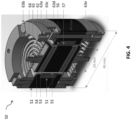
- FIG 4 represents an electromagnetic transducer 50 comprising a coil 51, an outer ferromagnetic element 52, a first magnet 53, an additional ferromagnetic element 54 and a central ferromagnetic element 55.
- the electromagnetic transducer 50 particularly comprises a protection 56 made of a non-ferromagnetic material which limits the risk of sticking between the central mass and the external ferromagnetic element 52.
- the electromagnetic transducer 50 comprises a flat spring 62 with three branches which connects the support to the central mass via a clip 64 and a nut 65 Clip 64 is bonded to the central mass by bonding one end of the disc-shaped clip to the central mass.
- the other opposite end of the attachment along the axis may comprise a threaded rod making it possible to compress the spring between the attachment 64 and the nut 62.
- the support particularly comprises a ring 63c and a ring 63e which hold the element external ferromagnetic 52 by means of a screw 63d.
- THE spring 62 is linked to the support by being compressed between a ring 63a and the ring 63c by means of a screw 63b.
- the electromagnetic transducer 50 comprises a coil support 57 facilitating the manufacture and connection of the coil 51 with the external ferromagnetic element 52.
- a coil support 57 can be used in other embodiments of the invention and is not particularly related to the embodiment of the figure 4 .
- the coil support 57 is optionally linked to the protection 56.
- the electromagnetic transducer 50 according to the figure 4 is an example of an electromagnetic transducer according to the present invention and does not limit the invention to this example.
- other connection means between the central mass and the support can be used.
- the spring can be linked to the support or to the central mass by other means, for example by welding, gluing or snap-fastening.
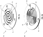
- THE figures 5a and 5b each represent a flat spiral spring with three branches, forming a disc extending radially around an axis passing through the middle of each spring.
- the flat spring 70 of the figure 5a comprises three branches 71, the branches forming spirals towards the middle 72 of the spring 70.
- the branches 71 of the spring 70 make approximately one turn around the axis passing through the middle 72 between the outside and the inside of the spring with respect to to the axis.
- the flat three-branch spiral spring of the figure 5a with a thickness of 0.5 mm would have an axial stiffness of approximately 16.8 N/mm and a radial stiffness of 803 N/mm.
- the flat spring 80 of the figure 5b comprises three branches 81, the branches forming spirals towards the middle 82 of the spring 80.
- the branches 81 of the spring 80 perform approximately one and a half turns around the axis passing through the middle 82 between the outside and the inside of the spring relative to the axis.
- the branches 81 of the spring 80 are thinner radially to the axis.
- the thickness of the spring 70 is less than the thickness of the spring 80. According to FEM simulations, the flat spring with three branches of the figure 5b with a thickness of 1 mm would have an axial stiffness of approximately 16.8 N/mm and a radial stiffness of 57 N/mm.
- the springs 70, 80 of the figures 5a and 5b are examples of the spring that the electromagnetic transducer of the invention may comprise.
- other springs and particularly other flat springs, can be used to implement the invention.
- a person skilled in the art would know how to adapt the thickness of the flat spring, the number of branches, the number of turns that the branches make between the outside and the inside of the spring with respect to the axis and the material or materials of the springs according to the environment in which the electromagnetic transducer is to be used and according to the dimensional constraints.
- the present three-branch spiral flat springs can be dimensioned so as to have an axial stiffness low enough so that the natural resonant frequency is close to 50 Hz.
- the radial stiffness of such flat springs is strong enough to guide the central mass along the first axis without the central mass and the support coming into physical contact, that is to say without sticking.
- electromagnetic transducers presented here can be used in groups rather than individually, so as to form an assembly. These electromagnetic transducers need not be identical and electromagnetic transducers according to different embodiments shown herein can be used together without limitations. They can in particular be arranged in series or in parallel. Particularly, the transducer coils electromagnetic elements of the same assembly can be connected in series and/or in parallel.
Landscapes
- Engineering & Computer Science (AREA)
- Power Engineering (AREA)
- Apparatuses For Generation Of Mechanical Vibrations (AREA)
- Reciprocating, Oscillating Or Vibrating Motors (AREA)
- Vibration Prevention Devices (AREA)
Abstract
La présente invention concerne un transducteur électromagnétique pour la récupération d'énergie vibratoire. Particulièrement, l'invention concerne un transducteur électromagnétique comprenant un support, une masse centrale, et au moins un ressort reliant la masse centrale au support, le ressort permettant le déplacement de la masse centrale par rapport au support selon un premier axe. La présente invention concerne également un ensemble de transducteurs électromagnétiques.
Description
- La présente invention concerne un transducteur électromagnétique pour la récupération d'énergie vibratoire. Particulièrement, l'invention concerne un transducteur électromagnétique comprenant un support, une masse centrale, et au moins un ressort reliant la masse centrale au support, le ressort permettant le déplacement de la masse centrale par rapport au support selon un premier axe. La présente invention concerne également un ensemble de transducteurs électromagnétiques.
- Les récupérateurs d'énergie vibratoire ont pour fonction d'alimenter électriquement des systèmes électroniques à partir des vibrations présentes dans leur environnement. Ceux-ci nécessitent moins de maintenance et engendrent moins de pollution que les batteries et sont particulièrement intéressants lorsque le système à alimenter se situe dans un endroit inaccessible, privé de lumière et de gradient thermique suffisant. Cependant l'industrialisation et la mise sur le marché de ces récupérateurs d'énergie vibratoire est verrouillée par leur robustesse encore insuffisante. En effet, bien que de nombreux récupérateurs soient théoriquement en mesure de fournir la puissance requise par leur application (alimentation de systèmes électroniques très basse consommation), ceux-ci sont souvent incapables de s'adapter aux fluctuations fréquentielles des sources vibratoires réelles. De plus ces récupérateurs d'énergie vibratoire sont utilisés dans des environnements sujets aux changements de température alors que ces récupérateurs sont inadaptés à de telles variations. Egalement, les récupérateurs d'énergie vibratoire résistent difficilement au vieillissement de leurs éléments constitutifs. Pour corriger ces problèmes sans faire chuter significativement leur densité de puissance (comme c'est souvent le cas concernant les stratégies à base d'ajustement mécanique, de système multimodes, ou encore de systèmes non résonants), l'une des pistes les plus prometteuses est l'ajustement électrique. Cette méthode consiste à maximiser le transfert de puissance entre la source vibratoire et la charge électrique, non seulement à la résonance (quand la fréquence de la vibration coïncide avec la fréquence de résonance naturelle du résonateur mécanique) mais aussi hors résonance, au moyen d'un circuit d'adaptation d'impédance situé au niveau de la charge électrique. Il en résulte un accroissement de la bande-passante effective du récupérateur, rendant donc ce dernier plus robuste aux conditions réelles d'utilisation.
- L'impact de l'ajustement électrique sur la bande-passante dépend premièrement du type de transducteur réalisant la conversion énergétique, le type de transducteur déterminant les équations physiques régissant le comportement du récupérateur. Notamment, il existe des transducteurs piézoélectriques et des transducteurs électromagnétiques. Secondement, l'ajustement électrique sur la bande-passante dépend des paramètres caractéristiques du récupérateur tels que la masse mobile rapportée au volume total (densité effective du récupérateur), le facteur de qualité mécanique, la fréquence de résonance mécanique, et le couplage. On parle de couplage piézoélectrique dans le cas d'un transducteur piézoélectrique, et de couplage électromagnétique dans le cas d'un transducteur électromagnétique.
- Dans le cas des transducteurs piézoélectriques, d'excellentes performances ont déjà été atteintes (bande-passante à -3dB supérieure à 10%) au moyen de récupérateurs fortement couplés associés à des circuits d'extraction très performants. Dans le cas des transducteurs électromagnétiques, de telles performances sont plus difficiles à atteindre à cause de leur couplage électromagnétique généralement trop faible. En condition de petit déplacement de la masse mobile autour d'un point de fonctionnement, la dérivée du flux magnétique dans le bobinage par rapport au déplacement du mobile s'appelle le coefficient de transduction électromagnétique, et le couplage d'un récupérateur électromagnétique peut être défini comme le carré de ce coefficient divisé par la résistance interne de la bobine et par le volume total du récupérateur. En d'autres termes, les performances des récupérateurs électromagnétiques sont limitées par le fait que, pour un déplacement donné du mobile, la variation de flux magnétique est souvent trop faible pour que la méthode d'ajustement électrique augmente significativement la bande-passante effective du récupérateur. Les performances de la stratégie d'ajustement électrique sont donc meilleures pour les récupérateurs piézoélectriques.
- Cependant les récupérateurs électromagnétiques présentent des avantages décisifs sur d'autres plans tels que la maturité technologique des procédés de fabrication, le coût, la résistance mécanique vis-à-vis des chocs et de l'utilisation sur le long terme, etc. C'est pourquoi le développement de récupérateurs de type électromagnétique demeure pertinent.
- L'invention vise à pallier tout ou partie des problèmes cités plus haut en proposant un transducteur électromagnétique permettant un fort couplage, significativement plus élevé que les récupérateurs électromagnétiques connus, ainsi qu'une densité effective élevée. Ainsi, l'invention vise à atteindre de meilleures performances en termes de bande-passante et de densité de puissance avec la méthode d'ajustement électrique.
- La méthode d'ajustement électrique se base sur le théorème de maximisation du transfert de puissance entre une source et une charge quelconques. D'après ce théorème, la puissance transférée est maximale quand l'impédance de la charge est égale au complexe conjugué de l'impédance de la source. La
figure 1 représente un modèle générique 10 décrivant le comportement des récupérateurs à transduction électromagnétique 11 sous hypothèse de petits déplacements, associés à un circuit d'adaptation d'impédance 12. Le récupérateur, délivrant la tension v et le courant i, est assimilé à la source tandis que le circuit d'adaptation constitue la charge. En contrôlant adéquatement les valeurs de condensateur Cload et de résistance Rload selon la fréquence d'entrée, il est possible de se placer dans les conditions du théorème à la résonance naturelle du récupérateur mais aussi hors résonance. - Certains dispositifs connus sont basés sur le déplacement relatif d'une source de champ magnétique par rapport à un bobinage. Le déplacement, e.g. la translation ou la rotation, d'un champ magnétique créé par un aimant entraîne une variation du flux magnétique dans un bobinage. Pour obtenir une dérivée du flux magnétique la plus forte possible avec ce type de dispositifs, il faut utiliser un guide ferromagnétique solidaire de l'aimant afin de canaliser les lignes du champ magnétique à l'endroit par lequel passe la bobine, tout en réduisant l'entrefer du circuit magnétique à son strict minimum. Cet entrefer minimal est l'épaisseur de la bobine (simplement parce que si l'entrefer était moins épais que l'épaisseur de la bobine, cette dernière ne pourrait plus passer au travers de l'ensemble constitué du guide ferromagnétique et de l'aimant). La bobine, quant à elle, doit être dimensionnée adéquatement pour maximiser la dérivée du flux magnétique en son sein. Notamment, une bobine trop peu épaisse conduit à une dérivée du flux magnétique trop faible même avec le guide ferromagnétique. Par conséquent, un compromis doit être trouvé entre l'épaisseur de l'entrefer et celle de la bobine, et ce compromis conduit à un couplage électromagnétique significativement inférieur au couplage électromagnétique atteignable avec les transducteurs basés sur une variation de champ magnétique (transducteurs pour lesquels l'épaisseur de l'entrefer est indépendante de l'épaisseur de la bobine). En revanche, les récupérateurs basés sur le déplacement relatif d'une source magnétique par rapport à un bobinage ont l'avantage de ne pas générer de force magnétique entre le mobile et la base du récupérateur, cette force étant à l'origine de difficultés de modélisation (calcul analytique complexe, non-linéarité), de conception et de fabrication. Notamment, il y a des possibilités de collage pendant la phase d'assemblage ou d'utilisation, ou la génération de frottements secs, etc.
- Certains récupérateurs sont des transducteurs basés sur une variation de la forme ou de l'intensité du champ magnétique créé par l'aimant. Il s'agit des transducteurs pour lesquels la variation de flux magnétique dans le bobinage est provoquée par une modification du champ magnétique créé par l'aimant au moyen d'éléments ferromagnétiques en mouvement par rapport à celui-ci. Le déplacement d'un mobile provoque une variation de l'épaisseur des entrefers, i.e. distance séparant le mobile du reste du guide ferromagnétique contenant les aimants. Cette variation d'entrefer entraîne une variation de la reluctance du circuit magnétique alimenté par les aimants, de sorte que le flux capté par la bobine est maximal quand le mobile est dans une position telle que l'entrefer est faible, et minimal dans une position telle que l'entrefer est élevé. Cependant, de tels dispositifs demandent une attention particulière concernant la force magnétique car celle-ci peut engendrer du collage ou du frottement sec si aucune disposition n'est prise pendant la conception du récupérateur.
- L'invention vise à pallier les problèmes cités précédemment en proposant un transducteur électromagnétique significativement moins sujet à du collage ou du frottement sec et qui est particulièrement compact.
- A cet effet, l'invention a pour objet un transducteur électromagnétique comprenant un support, une masse centrale, et au moins un ressort reliant la masse centrale au support, le ressort permettant le déplacement de la masse centrale par rapport au support selon un premier axe ; la masse centrale comprenant un élément ferromagnétique central, un premier aimant, un second aimant, et deux éléments ferromagnétiques supplémentaires, l'élément ferromagnétique étant flanqué d'un premier côté selon le premier axe par le premier aimant et flanqué d'un second côté, opposé au premier côté selon le premier axe, par le second aimant, le premier aimant et le second aimant étant chacun flanqué selon le premier axe par un des éléments ferromagnétiques supplémentaires ; le support entourant la masse centrale radialement au premier axe et un entrefer séparant le support de la masse centrale, le support comprenant au moins une bobine enroulée autour du premier axe et solidaire d'un élément ferromagnétique externe ; le transducteur électromagnétique étant configuré de manière à ce que le flux magnétique du premier aimant et le flux magnétique du second aimant suivent chacun un trajet parmi un premier trajet et un second trajet, le premier trajet ne traversant pas la bobine, le second trajet traversant la bobine et en poursuivant autour de la bobine par l'intermédiaire de l'élément ferromagnétique externe : le déplacement de la masse centrale selon le premier axe entrainant la modification du trajet d'au moins un des flux magnétiques depuis le premier trajet vers le second trajet ou inversement.
- Par « le ressort permettant le déplacement de la masse centrale par rapport au support selon un premier axe », il est entendu que le ressort est capable de se déformer en réponse à une vibration, sa déformation entraînant un déplacement de la masse centrale selon un premier axe.
- Par « flanqué d'un premier côté selon le premier axe et flanqué d'un second côté, opposé au premier côté selon le premier axe, par un second aimant, le premier aimant et le second aimant étant chacun flanqués selon le premier axe par un élément ferromagnétique supplémentaire », il est entendu que l'élément ferromagnétique central, le premier aimant, le second aimant et les éléments ferromagnétiques supplémentaires sont empilés axialement.
- Par « le support entourant la masse centrale radialement au premier axe et un entrefer séparant le support de la masse centrale », il est entendu que le support est disposé autour et à distance de la masse centrale. Cette distance est suffisamment grande pour que des vibrations qui entraîneraient le mouvement de la masse centrale n'entraînent pas de frottements entre la masse centrale et le support. Cet entrefer ou cette distance dépend essentiellement de la différence de raideur entre la force magnétique radiale tendant à éloigner la masse de son axe de translation, et la force mécanique radiale liée aux ressorts tendant à compenser la raideur magnétique et ramener la masse sur son axe de translation. Si cette différence est positive alors il est nécessaire ou bien d'augmenter la raideur radiale des ressorts si cela est possible ou bien d'augmenter l'entrefer en question afin de diminuer la raideur magnétique. L'entrefer est fonction des dimensions de la masse centrale et doit être apprécié selon la marge de tolérance technique de sa méthode de fabrication et selon une tolérance de dilatation thermique selon l'environnement d'utilisation.
- Par « une bobine enroulée autour de l'axe », il est entendu que la bobine est disposée radialement au premier axe.
- Par « le flux magnétique du premier aimant et le flux magnétique du second aimant suivent chacun un trajet », il est entendu que la répartition spatiale du champ magnétique et notamment la majorité des lignes du champ magnétique sont guidées selon un trajet spécifique.
- Dans « le premier trajet ne traversant pas la bobine » et « le second trajet traversant la bobine et en poursuivant autour de la bobine », il est entendu par « traverser la bobine » que les lignes du champ magnétique sont guidées de manière à traverser le plan radial dans lequel la bobine est disposée par rapport au premier axe. Par « autour de la bobine », il est entendu que les lignes du champ magnétique sont guidées pour former une boucle allant d'un pôle à l'autre d'un même aimant, la boucle s'enroulant autour de la bobine.
- Le transducteur électromagnétique de la présente invention combine donc (i) le déplacement relatif d'une source magnétique, ici la masse centrale comprenant un premier aimant et un second aimant, par rapport à un bobinage, ici le support comprenant la bobine enroulée et (ii) une variation du champ magnétique créés par les aimants de la masse centrale selon les éléments ferromagnétiques qui sont en mouvement (éléments ferromagnétiques compris dans la masse centrale) ou non (éléments ferromagnétiques compris dans le support). De plus, le transducteur électromagnétique de la présente invention comprend un entrefer réduit au minimum, l'entrefer étant seulement suffisamment grand pour séparer le support de la masse centrale et permettre le mouvement de la masse centrale par rapport au support. Ces avantages permettent une amélioration considérable de la densité effective du transducteur électromagnétique ainsi que du facteur de qualité mécanique et du couplage. Egalement, les éléments ferromagnétiques permettent d'accroître la dérivée du flux magnétique par rapport au déplacement de la masse centrale ainsi que le coefficient de transduction.
- Selon la présente invention, la bobine est située sur le support qui lors de l'utilisation du transducteur électromagnétique est fixe. Ainsi, la bobine ne subit pas le mouvement de la masse centrale et le risque de rupture par répétition de mouvement est réduit. Egalement, le transducteur électromagnétique de la présente invention est adapté pour que la masse centrale occupe un volume maximal dans le transducteur électromagnétique, ce qui permet de maximiser la densité effective et le couplage électromagnétique.
- De plus, le transducteur électromagnétique de la présente invention peut être réalisé en utilisant des aimants de forme et de magnétisation standards, diminuant les coûts de fabrication ou d'assemblage ainsi que les coûts potentiels d'entretien.
- En outre, le transducteur électromagnétique permet un déplacement de la masse centrale qui n'est limité que selon le premier axe et par le ressort, aucun autre élément compris dans le transducteur électromagnétique ne limitant la course de la masse centrale. Ainsi, le dimensionnement du transducteur électromagnétique de la présente invention est simple et indépendant du déplacement de la masse centrale.
- Avantageusement, le ressort du transducteur électromagnétique de l'invention comprend un premier ressort fixé sur une face externe d'un des éléments ferromagnétiques supplémentaires et un second ressort fixé sur une face externe de l'autre élément ferromagnétique supplémentaire.
- Avantageusement, le ressort du transducteur électromagnétique de l'invention comprend au moins un ressort plat s'étendant principalement dans un plan perpendiculaire au premier axe, étant préférablement un ressort en spirales à trois branches.
- Avantageusement, la bobine du transducteur électromagnétique de l'invention est entièrement noyée dans l'élément ferromagnétique externe.
- Avantageusement, la masse centrale du transducteur électromagnétique de l'invention est flanquée d'au moins un côté selon le premier axe par un troisième aimant et un élément ferromagnétique supplémentaire.
- Avantageusement, le support du transducteur électromagnétique de l'invention comprend plusieurs bobines.
- Avantageusement, les axes des pôles du premier et du second aimant du transducteur électromagnétique de l'invention sont inversés selon le premier axe.
- Avantageusement, la masse centrale du transducteur électromagnétique de l'invention est cylindrique.
- Avantageusement, le transducteur électromagnétique de l'invention comprend en outre une protection de la bobine.
- L'invention concerne également un ensemble de transducteurs électromagnétiques tels que décrits précédemment, les bobines des transducteurs électromagnétiques étant reliées entre elles en parallèle et/ou en série.
- D'autres caractéristiques, détails et avantages de l'invention ressortiront à la lecture de la description faite en référence au dessin annexé donné à titre d'exemple et qui représente :
- La
figure 1 représente un modèle décrivant le comportement de modèle générique de récupérateurs à transduction électromagnétique sous hypothèse de petits déplacements, associé à un circuit d'adaptation d'impédance. - La
figure 2 représente de façon schématique un transducteur électromagnétique dont la masse centrale est en position d'équilibre. - La
figure 3 représente de façon schématique un transducteur électromagnétique dont la masse centrale est déplacée par rapport à la position d'équilibre et selon un premier axe. - La
figure 4 représente de façon schématique un transducteur électromagnétique dont la masse centrale est déplacée par rapport à la position d'équilibre, selon un premier axe et inversement au déplacement de la masse centrale dans lafigure 3 . - La
figure 5a représente un ressort plat en spirale à trois branches d'épaisseur 0,5 mm. - La
figure 5b représente un ressort plat en spirale à trois branches d'épaisseur 1mm. - Préférentiellement, le transducteur électromagnétique de la présente invention présente une structure essentiellement axisymétrique pouvant être contenue dans un volume simple tel qu'un cylindre. Ceci permet notamment de minimiser les effets de bord du champ magnétique, de minimiser le volume perdu par son conditionnement et de faciliter son intégration dans un contexte générique. En outre, la structure essentiellement axisymétrique du transducteur électromagnétique de la présente invention permet d'accélérer la convergence des simulations FEM nécessaires à son dimensionnement.
- La
figure 2 représente un transducteur électromagnétique 20 selon l'invention, étant notamment dans une position d'équilibre, de repos, c'est-à-dire la position à laquelle se situe la masse centrale lorsqu'aucune vibration n'affecte le transducteur électromagnétique. Le transducteur électromagnétique 20 comprend un élément ferromagnétique central 25 flanqué d'un premier côté selon le premier axe 27 par un premier aimant 21 ayant une face 21a en regard de l'élément ferromagnétique central 25 et une face opposée 21b. Ce premier aimant 21 est flanqué selon le premier axe 27 et en regard de sa face opposée 21b par un élément ferromagnétique supplémentaire 23. L'élément ferromagnétique 25 est flanqué d'un second côté selon le premier axe 27 et opposé au premier côté par un second aimant 22 ayant une face 22a en regard de l'élément ferromagnétique central 25 et une face opposée 22b. Ce second aimant 22 est flanqué selon le premier axe 27 et en regard de sa face opposée 22b par un élément ferromagnétique supplémentaire 24. Le premier aimant et le second aimant sont disposés de manière à ce que les faces opposées selon le premier axe constituent chacune un pôle, c'est-à-dire que la face 21a corresponde au pôle nord ou sud tandis que la face 21b corresponde au pôle opposé, de même pour les faces 22a et 22b. - Préférentiellement, les éléments formant la masse centrale, c'est-à-dire l'élément ferromagnétique central 25, le premier aimant 21, le second aimant 22 et les éléments ferromagnétiques supplémentaires 23, 24 sont des cylindres, de préférence des cylindres de révolution.
- Le transducteur électromagnétique 20 comprend également un support 30 entourant la masse centrale radialement au premier axe et un entrefer séparant le support 30 de la masse centrale. Le support 30 comprend une bobine 31 enroulée autour du premier axe et solidaire d'un élément ferromagnétique externe 32. L'élément ferromagnétique externe 32 est notamment d'un seul bloc. En effet, lorsque l'élément ferromagnétique externe 32 est en plusieurs parties, la présence de jonctions entre ses parties peut perturber les flux magnétiques 28, 29. Lorsque la bobine 31 est enfermée au moins partiellement dans l'élément ferromagnétique externe 32, c'est-à-dire que chacune de ses faces est au moins partiellement recouverte par une partie de l'élément ferromagnétique externe 32, ce dernier ce doit alors d'être en plusieurs parties. L'élément ferromagnétique externe 32 peut notamment comprendre un logement ouvert sur la masse centrale 21 dans lequel est insérée la bobine 31, comme représenté. La bobine 31 peut notamment être affleurant à la surface de l'élément ferromagnétique externe 32 ou bien en retrait de de la surface de ce dernier. En particulier, la bobine est dimensionnée pour être en retrait de la surface de ce dernier, ce qui limite les jeux fonctionnels. En particulier, le logement est configuré pour que la bobine 31 soit disposée en regard seulement de l'élément ferromagnétique central 25 dans la position d'équilibre du transducteur électromagnétique 20, comme représenté. Ainsi, dans un mode de réalisation avantageux, la hauteur de la bobine 31 est inférieure ou égale à celle de l'élément ferromagnétique central 25. Le chemin des flux magnétiques 29, 29 des aimants 21, 22 n'est donc pas influencé par la bobine 31 dans la position d'équilibre du transducteur électromagnétique 20. Il n'est alors pas nécessaire de recouvrir la bobine 31 partiellement sur la face en regard de la masse centrale 21 par un élément ferromagnétique, ce recouvrement étant réalisé dans le but d'éviter une modification du flux magnétique 28, 29 du premier et du second aimants 21, 22 dans la position d'équilibre. Ainsi, avantageusement, comme la bobine 31 n'est pas recouverte sur sa face en regard de la masse centrale 21, et l'entrefer séparant ces deux éléments est dès lors plus faible qu'avec un recouvrement, et le transducteur électromagnétique 20 se retrouve plus compact. De par cet entrefer plus faible, comme il est décrit en détail plus loin, le passage des flux magnétiques 28, 29 d'un chemin court (où ils ne traversent pas la bobine 31) à chemin long (où ils traversent la bobine 31) est plus facile et donc le transducteur électromagnétique 20 est plus performant. Dans le mode particulier de la
figure 2 , la bobine 31 se situe au plus proche radialement de la masse centrale et l'élément ferromagnétique externe entoure la bobine radialement et selon le premier axe, c'est-à-dire que seule une partie centrale de la face du support 30 la plus proche radialement de la masse centrale comprend la bobine. - Dans l'invention, la bobine 31 joue avantageusement à la fois le rôle de générateur de courant, par la modification du chemin des flux magnétiques 28, 29, et à la fois d'isolant, ce qui permet de réduire l'entrefer séparant la masse centrale 21 de la bobine 31 et donc d'obtenir un transducteur électromagnétique 20 compact.
- Le flux magnétique 29 du premier aimant 21 décrit une boucle allant d'un pôle de celui-ci à un autre, c'est-à-dire d'une face 21a à une face 21b ou inversement, et étant guidées par l'élément ferromagnétique central 25, l'élément ferromagnétique externe 32 et l'élément ferromagnétique supplémentaire 23. Le flux magnétique 29 ne traverse pas la bobine 31. Le flux magnétique 28 du second aimant 22 décrit une boucle allant d'un pôle de celui-ci à un autre, c'est-à-dire d'une face 22a à une face 22b ou inversement, et étant guidées par l'élément ferromagnétique central 25, l'élément ferromagnétique externe 32 et l'élément ferromagnétique supplémentaire 24. Le flux magnétique 28 ne traverse pas la bobine 31.
- La
figure 3 représente un transducteur électromagnétique 20 similaire au transducteur électromagnétique de lafigure 2 mais dont la masse centrale n'est pas dans une position de repos. Suite à une vibration, le ressort a pu être déformé et la masse centrale s'est déplacée par rapport au support selon le premier axe 27 et selon la direction 33. Lors de cette vibration, le déplacement de la masse centrale entraîne une modification d'au moins un des trajets suivis par le flux magnétique d'un des aimants par rapport à la bobine 31. Ainsi, la bobine 31 se retrouve au moins partiellement en regard du premier aimant 21 ou du second aimant 22, ce qui influe sur le chemin du flux magnétique 28, 29 correspondant. Dans lafigure 3 , la bobine 31 est partiellement en regard du second aimant 22 et le flux magnétique 28 du second aimant 22 est modifié et traverse la bobine 31, poursuivant autour de la bobine 31, guidée par l'élément ferromagnétique central 25, l'élément ferromagnétique externe 32 et l'élément ferromagnétique supplémentaire 24. La modification du trajet du flux magnétique 28 entraîne une augmentation du couplage électromagnétique et donc augmente la bande-passante effective du transducteur électromagnétique, sous réserve que celui-ci soit associé à un circuit d'adaptation d'impédance. - Suite à ce déplacement de la masse centrale selon le premier axe 27 par rapport au support 30 et selon une direction 33, la masse centrale se déplacera dans la direction du premier axe 27 selon un mouvement d'oscillation autour de sa position d'équilibre, ce qui entrainera à nouveau la modification du trajet du flux magnétique 28 vers le chemin court dans la mesure où la bobine 31 ne sera plus en regard du second aimant 22, et, si le déplacement de la masse central est suffisant, entrainera la mise en regard de la bobine 31 avec le premier aimant 21 et la modification du trajet du flux magnétique 29 du premier aimant de manière à ce que celui traverse la bobine 31.
- La
figure 4 représente un transducteur électromagnétique 50 comprenant une bobine 51, un élément ferromagnétique externe 52, un premier aimant 53, un élément ferromagnétique supplémentaire 54 et un élément ferromagnétique central 55. Le transducteur électromagnétique 50 comprend particulièrement une protection 56 en un matériau non ferromagnétique qui limite le risque de collage entre la masse centrale et l'élément ferromagnétique externe 52. Le transducteur électromagnétique 50 comprend un ressort plat 62 à trois branches qui relie le support à la masse centrale par l'intermédiaire d'une attache 64 et d'un écrou 65. L'attache 64 est liée à la masse centrale par un collage d'une extrémité de l'attache en forme de disque à la masse centrale. L'autre extrémité opposée de l'attache selon l'axe peut comprendre une tige filetée permettant de comprimer le ressort entre l'attache 64 et l'écrou 62. Le support comprend particulièrement un anneau 63c et un anneau 63e qui maintiennent l'élément ferromagnétique externe 52 au moyen d'une vis 63d. Le ressort 62 est lié au support en étant comprimé entre un anneau 63a et l'anneau 63c au moyen d'une vis 63b. - Le transducteur électromagnétique 50 selon la
figure 4 comprend un support de bobine 57 facilitant la fabrication et la liaison de la bobine 51 avec l'élément ferromagnétique externe 52. Un tel support de bobine 57 peut être utilisé dans d'autres modes de réalisation de l'invention et n'est pas particulièrement lié au mode de réalisation de lafigure 4 . Notamment, le support de bobine 57 est facultativement lié à la protection 56. - Le transducteur électromagnétique 50 selon la
figure 4 est un exemple de transducteur électromagnétique selon la présente invention et ne limite pas l'invention à cet exemple. Notamment, d'autres moyens de liaison entre la masse centrale et le support peuvent être utilisés. Egalement, le ressort peut être lié au support ou à la masse centrale par d'autres moyens, par exemple par soudure, collage ou encliquetage. - Les dimensions indiquées sur la
figure 4 , notamment une hauteur totale de 44 mm de hauteur, une largeur totale de 46mm et une largeur de la masse centrale de 20 mm sont données à titre indicatif et un transducteur électromagnétique selon l'invention peut avoir d'autres dimensions. - Les
figures 5a et 5b représentent chacune un ressort plat à spirale à trois branches, formant un disque s'étendant radialement autour d'un axe passant par le milieu de chaque ressort. Le ressort plat 70 de lafigure 5a comprend trois branches 71, les branches formant des spirales vers le milieu 72 du ressort 70. Les branches 71 du ressort 70 effectuent environ un tour autour de l'axe passant par le milieu 72 entre l'extérieur et l'intérieur du ressort par rapport à l'axe. D'après des simulations FEM, le ressort plat à spirale à trois branches de lafigure 5a avec une épaisseur de 0,5 mm aurait une raideur axiale d'environ 16.8 N/mm et une raideur radiale de 803 N/mm. Le ressort plat 80 de lafigure 5b comprend trois branches 81, les branches formant des spirales vers le milieu 82 du ressort 80. Les branches 81 du ressort 80 effectuent environ un tour et demi autour de l'axe passant par le milieu 82 entre l'extérieur et l'intérieur du ressort par rapport à l'axe. Les branches 81 du ressort 80 sont plus fines radialement à l'axe. L'épaisseur du ressort 70 est inférieure à l'épaisseur du ressort 80. D'après des simulations FEM, le ressort plat à trois branches de lafigure 5b avec une épaisseur de 1 mm aurait une raideur axiale d'environ 16.8 N/mm et une raideur radiale de 57 N/mm. - Les ressorts 70, 80 des
figures 5a et 5b sont des exemples de ressort que le transducteur électromagnétique de l'invention peut comprendre. Cependant d'autres ressorts, et particulièrement d'autres ressorts plats peuvent être utilisés pour mettre en œuvre l'invention. L'homme du métier saurait adapter l'épaisseur du ressort plat, le nombre de branches, le nombre de tour qu'effectuent les branches entre l'extérieur et l'intérieur du ressort par rapport à l'axe et le ou les matériaux des ressorts en fonction de l'environnement dans lequel doit être utilisé le transducteur électromagnétique et en fonction des contraintes dimensionnelles. - Les ressorts plats en spirale à trois branches présentes peuvent être dimensionnés de sorte à avoir une raideur axiale suffisamment faible pour que la fréquence de résonance naturelle soit proche de 50 Hz. De manière opposée, la raideur radiale de tels ressorts plats est suffisamment forte pour guider la masse centrale le long du premier axe sans que la masse centrale et le support n'entrent en contact physique, c'est-à-dire sans collage.
- En supposant un facteur de qualité d'un transducteur électromagnétique selon la présente invention à 100, une fréquence de résonance de 50 Hz et que ce transducteur électromagnétique est soumis à une vibration dont l'amplitude en accélération équivaut à 0,5 m/s2 tandis que la fréquence est définie sur une plage centrée autour de 50 Hz, une estimation de la puissance récupérable peut être obtenue. En prenant l'exemple d'un volume du plus petit cylindre pouvant contenir le transducteur électromagnétique étant de 73 cm2, la densité de puissance normalisée maximale serait de l'ordre de 28 kg.s/m3. Selon cet exemple la bande passante effective à -3 dB équivaut à 4,2 Hz
- Différents transducteurs électromagnétiques présentés ici peuvent être utilisés en groupe plutôt qu'individuellement, de manière à former un ensemble. Il n'est pas nécessaire que ces transducteurs électromagnétiques soient identiques et des transducteurs électromagnétiques selon différents modes de réalisation présentés ici peuvent être utilisés ensemble sans limitations. Ils peuvent notamment être disposés en série ou en parallèle. Particulièrement, les bobines des transducteurs électromagnétiques d'un même ensemble peuvent être reliées en série et/ou en parallèle.
- Les différents modes de réalisation présentés dans cette description ne sont pas limitatifs et peuvent être combinés entre eux. En outre, la présente invention n'est pas limitée aux modes de réalisation précédemment décrits mais s'étend à tout mode de réalisation entrant dans la portée des revendications.
Claims (10)
- Transducteur électromagnétique (20) comprenant un support (30), une masse centrale (21, 22, 23, 24, 25), et au moins un ressort reliant la masse centrale au support, le ressort permettant le déplacement de la masse centrale par rapport au support selon un premier axe (27),la masse centrale comprenant un élément ferromagnétique central (25), un premier aimant (21), un second aimant (22), et deux éléments ferromagnétiques supplémentaires (23, 24), l'élément ferromagnétique étant flanqué d'un premier côté selon le premier axe par le premier aimant (21) et flanqué d'un second côté, opposé au premier côté selon le premier axe, par le second aimant (22), le premier aimant et le second aimant étant chacun flanqué selon le premier axe par un des éléments ferromagnétiques supplémentaires (23, 24),le support (30) entourant la masse centrale radialement au premier axe et un entrefer séparant le support de la masse centrale, le support comprenant au moins une bobine (31) enroulée autour du premier axe et solidaire d'un élément ferromagnétique externe (32),le transducteur électromagnétique étant configuré de manière à ce que le flux magnétique (29) du premier aimant (21) et le flux magnétique (28) du second aimant (22) suivent chacun un trajet parmi un premier trajet et un second trajet, le premier trajet ne traversant pas la bobine, le second trajet traversant la bobine et en poursuivant autour de la bobine (31) par l'intermédiaire de l'élément ferromagnétique externe,le déplacement de la masse centrale selon le premier axe entrainant la modification du trajet d'au moins un des flux magnétiques (28, 29) depuis le premier trajet vers le second trajet ou inversement.
- Le transducteur électromagnétique (20) selon la revendication 1, le ressort comprenant un premier ressort fixé sur une face externe d'un des éléments ferromagnétiques supplémentaires (23, 24) et un second ressort fixé sur une face externe de l'autre élément ferromagnétique supplémentaire (23, 24).
- Le transducteur électromagnétique (20) selon l'une des revendications, le ressort comprenant au moins un ressort plat (70, 80) s'étendant principalement dans un plan perpendiculaire au premier axe (27), étant préférablement un ressort en spirales à trois branches (71, 81).
- Le transducteur électromagnétique (20) selon l'une des revendications précédentes, la bobine (31) étant entièrement noyée dans l'élément ferromagnétique externe (32).
- Le transducteur électromagnétique (20) selon l'une des revendications précédentes, la masse centrale étant flanquée d'au moins un côté selon le premier axe (27) par un troisième aimant et un élément ferromagnétique supplémentaire.
- Le transducteur électromagnétique (20) selon la revendication 5, le support (30) comprenant plusieurs bobines (31).
- Le transducteur électromagnétique (20) selon l'une des revendications précédentes, les axes des pôles du premier et du second aimant étant inversés selon le premier axe (27).
- Le transducteur électromagnétique (20) selon l'une des revendications précédentes, la masse centrale étant cylindrique.
- Le transducteur électromagnétique (50) selon l'une des revendications précédentes, comprenant en outre une protection (57) de la bobine (1).
- Ensemble de transducteurs électromagnétiques selon l'une des revendications précédentes, les bobines des transducteurs électromagnétiques étant reliées entre elles en parallèle et/ou en série.
Applications Claiming Priority (1)
| Application Number | Priority Date | Filing Date | Title |
|---|---|---|---|
| FR2112868A FR3130091B1 (fr) | 2021-12-02 | 2021-12-02 | Transducteur électromagnétique pour la récupération d’énergie vibratoire |
Publications (1)
| Publication Number | Publication Date |
|---|---|
| EP4191847A1 true EP4191847A1 (fr) | 2023-06-07 |
Family
ID=80786774
Family Applications (1)
| Application Number | Title | Priority Date | Filing Date |
|---|---|---|---|
| EP22210756.7A Pending EP4191847A1 (fr) | 2021-12-02 | 2022-12-01 | Transducteur electromagnetique pour la recuperation d'energie vibratoire |
Country Status (3)
| Country | Link |
|---|---|
| US (1) | US20230179121A1 (fr) |
| EP (1) | EP4191847A1 (fr) |
| FR (1) | FR3130091B1 (fr) |
Citations (4)
| Publication number | Priority date | Publication date | Assignee | Title |
|---|---|---|---|---|
| WO2008132423A1 (fr) * | 2007-04-27 | 2008-11-06 | Perpetuum Ltd. | Générateur d'aimant permanent pour conversion d'énergie vibrationnelle mécanique en énergie électrique |
| US7569952B1 (en) * | 2003-04-18 | 2009-08-04 | Ferro Solutions, Inc. | High efficiency, inductive vibration energy harvester |
| JP2010115034A (ja) * | 2008-11-07 | 2010-05-20 | Isuzu Motors Ltd | 直動発電機 |
| CN105932856A (zh) * | 2016-06-28 | 2016-09-07 | 西安陆洲智能传感技术有限公司 | 一种高输出振动型磁电发电机 |
Family Cites Families (199)
| Publication number | Priority date | Publication date | Assignee | Title |
|---|---|---|---|---|
| US2789177A (en) * | 1954-10-25 | 1957-04-16 | Mallory & Co Inc P R | Synchronous vibrators |
| AT245115B (de) * | 1964-08-11 | 1966-02-10 | Ife Ges Fuer Maschinen Und App | Schaltung zur Erzeugung von in der Phasenlage verschiebbaren Impulsen zur Stromsteuerung von Antriebsmagneten für Vibrationsgeräte |
| US3501745A (en) * | 1965-07-15 | 1970-03-17 | Lear Siegler Inc | Frequency selective resonant reed detector |
| CH511469A (de) * | 1969-02-05 | 1971-02-26 | Foerderung Forschung Gmbh | Als Zeitgebernormal in elektrischen Zeitmessgeräten dienender mechanischer Resonator |
| US3602842A (en) * | 1969-08-08 | 1971-08-31 | Scudder Smith | Electromechanical oscillator including a dual vibrator for producing a bent frequency |
| JPS53140603A (en) * | 1977-05-16 | 1978-12-07 | Enomoto Maikuroponpu Seisakush | Reciprocating type electromagnetic pump |
| NL175856C (nl) * | 1979-12-21 | 1987-12-16 | Terra Dynamics B V | Omzetter voor het opnemen van mechanische trillingen en een met een dergelijke omzetter gevormde seismometer, benevens een schakeling voor het in subgroepen onderverdelen van een aantal van zulke seismometers. |
| US4555682A (en) * | 1983-03-02 | 1985-11-26 | Fujitsu Limited | Mechanical filter |
| FR2562446A1 (fr) * | 1984-04-04 | 1985-10-11 | Hayashibara Ken | Generateur de vibration electromagnetique |
| US4639905A (en) * | 1984-12-03 | 1987-01-27 | Western Geophysical Co. Of America | Dual-mode vibrator |
| FR2662099B1 (fr) * | 1990-05-18 | 1994-08-05 | Mecanique Magnetique Sa | Vibreur basse frequence a grande amplitude. |
| JP3003429B2 (ja) * | 1992-10-08 | 2000-01-31 | 富士電機株式会社 | ねじり振動子および光偏向子 |
| JPH06189568A (ja) * | 1992-12-11 | 1994-07-08 | Nikon Corp | 波動循環型アクチュエータ |
| US6218767B1 (en) * | 1996-01-08 | 2001-04-17 | Canon Kabushiki Kaisha | Vibration device |
| US6057554A (en) * | 1997-05-12 | 2000-05-02 | Plesko; George A. | Reflective switch |
| CN100490996C (zh) * | 1999-04-16 | 2009-05-27 | 并木精密宝石株式会社 | 震动驱动器的供电机构 |
| US6825575B1 (en) * | 1999-09-28 | 2004-11-30 | Borealis Technical Limited | Electronically controlled engine generator set |
| US6501357B2 (en) * | 2000-03-16 | 2002-12-31 | Quizix, Inc. | Permanent magnet actuator mechanism |
| DE60115989T2 (de) * | 2000-06-07 | 2006-09-21 | Matsushita Electric Works, Ltd., Kadoma | Lineare Schwingungsvorrichtung |
| JP3591429B2 (ja) * | 2000-06-22 | 2004-11-17 | オムロンヘルスケア株式会社 | 流量コントロール弁及び血圧計 |
| US6809486B2 (en) * | 2000-12-15 | 2004-10-26 | Stirling Technology Company | Active vibration and balance system for closed cycle thermodynamic machines |
| JP3558986B2 (ja) * | 2001-02-01 | 2004-08-25 | Necトーキン岩手株式会社 | 電磁型発音体 |
| US6413117B1 (en) * | 2001-02-28 | 2002-07-02 | Palm, Inc. | Axisymmetric vibrator, vibrator connection, and mounting system |
| JP2002368577A (ja) * | 2001-04-06 | 2002-12-20 | Murata Mfg Co Ltd | 二重モードフィルタ |
| US6936937B2 (en) * | 2002-06-14 | 2005-08-30 | Sunyen Co., Ltd. | Linear electric generator having an improved magnet and coil structure, and method of manufacture |
| AU2003301464A1 (en) * | 2002-10-16 | 2004-05-04 | Matsushita Refrigeration Company | Linear motor and liner compressor using the same |
| JP2004261684A (ja) * | 2003-02-28 | 2004-09-24 | Citizen Electronics Co Ltd | 振動体及びその製造方法 |
| JP4492252B2 (ja) * | 2003-09-05 | 2010-06-30 | セイコーエプソン株式会社 | アクチュエータ |
| US7355305B2 (en) * | 2003-12-08 | 2008-04-08 | Shen-Etsu Chemical Co., Ltd. | Small-size direct-acting actuator |
| US7518287B2 (en) * | 2004-06-07 | 2009-04-14 | Panasonic Corporation | Actuator fine motion mechanism including the actuator, and camera module including the fine motion mechanism |
| KR100541112B1 (ko) * | 2004-07-01 | 2006-01-11 | 삼성전기주식회사 | 분동내장형 수직진동자 |
| KR100568315B1 (ko) * | 2004-09-24 | 2006-04-05 | 삼성전기주식회사 | 통신단말기용 멀티 모드 진동발생장치 |
| JP2006170071A (ja) * | 2004-12-15 | 2006-06-29 | Denso Corp | フリーピストンエンジンの制御装置及び制御方法 |
| US7652401B2 (en) * | 2005-02-07 | 2010-01-26 | Lg Innotek Co., Ltd. | Flat vibration motor |
| US7449803B2 (en) * | 2005-03-21 | 2008-11-11 | Sahyoun Joseph Y | Electromagnetic motor to create a desired low frequency vibration or to cancel an undesired low frequency vibration |
| US7576454B2 (en) * | 2005-05-23 | 2009-08-18 | Ciiis, Llc | Multiple magnet coil in gap generator |
| US7755227B2 (en) * | 2005-10-19 | 2010-07-13 | Alps Electric Co., Ltd. | Vibration generator |
| US7538463B2 (en) * | 2006-01-10 | 2009-05-26 | Citizen Electronics Co., Ltd. | Vibrator |
| GB2438255B (en) * | 2006-02-23 | 2009-10-21 | Citizen Electronics | Vibrator |
| JP2008225690A (ja) * | 2007-03-09 | 2008-09-25 | Sony Corp | 振動体、触覚機能付きの入力装置及び電子機器 |
| FR2919495B1 (fr) * | 2007-07-30 | 2010-11-19 | Oreal | Dispositif vibrant de massage |
| JP2009195895A (ja) * | 2007-10-11 | 2009-09-03 | Citizen Electronics Co Ltd | 振動発生装置及びその製造方法 |
| GB2446685B (en) * | 2007-11-27 | 2009-04-01 | Perpetuum Ltd | An electromechanical generator for converting mechanical vibrational energy into electrical energy |
| JP5237048B2 (ja) * | 2008-02-13 | 2013-07-17 | 日立オートモティブシステムズ株式会社 | 回転電機、および固定子巻線 |
| US8222782B2 (en) * | 2008-02-29 | 2012-07-17 | Nidec Copal Corporation | Brushless motor |
| EP2105214B1 (fr) * | 2008-03-28 | 2018-09-12 | ABI Anlagentechnik-Baumaschinen-Industriebedarf Maschinenfabrik und Vertriebsgesellschaft mbH | Dispositif de production de vibrations |
| US8115581B2 (en) * | 2008-04-04 | 2012-02-14 | Correlated Magnetics Research, Llc | Techniques for producing an electrical pulse |
| GB2459269B (en) * | 2008-04-15 | 2010-09-29 | Perpetuum Ltd | An electromechanical generator for, and method of, converting mechanical vibrational energy into electrical energy |
| US20090267423A1 (en) * | 2008-04-23 | 2009-10-29 | Hiroo Kajiwara | Electromagnetic exciter |
| US20110133577A1 (en) * | 2008-08-18 | 2011-06-09 | In Ho Lee | Horizontal linear vibration device |
| JPWO2010026883A1 (ja) * | 2008-09-05 | 2012-02-02 | 三洋電機株式会社 | リニアモータおよびリニアモータを備えた携帯機器 |
| US8358039B2 (en) * | 2008-10-17 | 2013-01-22 | Massachusetts Institute Of Technology | High-scan rate positioner for scanned probe microscopy |
| EP2348621B1 (fr) * | 2008-10-22 | 2017-02-22 | Sinfonia Technology Co., Ltd. | Actionneur linéaire |
| JP2010104864A (ja) * | 2008-10-28 | 2010-05-13 | Sanyo Electric Co Ltd | 往復振動発生器 |
| WO2010050224A1 (fr) * | 2008-10-31 | 2010-05-06 | ミツミ電機株式会社 | Actionneur et brosse à dents électrique le mettant en œuvre |
| JP5176891B2 (ja) * | 2008-11-14 | 2013-04-03 | ミツミ電機株式会社 | アクチュエータ及びこれを用いた電動歯ブラシ |
| JP4670942B2 (ja) * | 2008-11-21 | 2011-04-13 | トヨタ自動車株式会社 | 回転電機 |
| JP2010166802A (ja) * | 2008-12-15 | 2010-07-29 | Denso Corp | 回転電機の固定子 |
| US7948124B1 (en) * | 2009-01-28 | 2011-05-24 | The United States Of America As Represented By The Secretary Of The Navy | Electro-magnetic kinetic energy harvesting device using increased magnetic edge area |
| CN201388144Y (zh) * | 2009-02-20 | 2010-01-20 | 瑞声声学科技(常州)有限公司 | 扁平线性振动电机 |
| KR101018214B1 (ko) * | 2009-03-16 | 2011-02-28 | 삼성전기주식회사 | 리니어 진동 모터 |
| KR20100116335A (ko) * | 2009-04-22 | 2010-11-01 | 엘지이노텍 주식회사 | 선형 진동기 |
| KR101022945B1 (ko) * | 2009-05-12 | 2011-03-16 | 삼성전기주식회사 | 브러시리스 진동모터 |
| CN101902115B (zh) * | 2009-05-25 | 2013-02-13 | 三星电机株式会社 | 线性振动器 |
| CN101908815B (zh) * | 2009-06-02 | 2015-04-08 | 易音特电子株式会社 | 双模振动器 |
| KR101059599B1 (ko) * | 2009-07-01 | 2011-08-25 | 삼성전기주식회사 | 선형 진동모터 |
| KR101090428B1 (ko) * | 2009-07-07 | 2011-12-07 | 삼성전기주식회사 | 선형 진동자 |
| EP2456982A4 (fr) * | 2009-07-22 | 2017-06-14 | Vbox Incorporated | Pompe de fluide gazeux |
| KR101084860B1 (ko) * | 2009-07-22 | 2011-11-21 | 삼성전기주식회사 | 수평 리니어 진동자 |
| US9553497B2 (en) * | 2009-07-22 | 2017-01-24 | Mplus Co., Ltd. | Horizontal linear vibrator |
| KR101156780B1 (ko) * | 2009-07-22 | 2012-06-18 | 삼성전기주식회사 | 수평 리니어 진동자 |
| KR101077374B1 (ko) * | 2009-07-22 | 2011-10-26 | 삼성전기주식회사 | 수평 리니어 진동자 |
| GB2469347B (en) * | 2009-08-26 | 2011-10-05 | Perpetuum Ltd | An electromechanical generator for converting mechanical vibrational energy into electrical energy |
| KR101069997B1 (ko) * | 2009-09-11 | 2011-10-04 | 삼성전기주식회사 | 리니어 진동 모터 |
| KR101077446B1 (ko) * | 2009-09-11 | 2011-10-26 | 삼성전기주식회사 | 수평 리니어 진동자 |
| KR101079448B1 (ko) * | 2009-09-24 | 2011-11-03 | 삼성전기주식회사 | 수평 진동자 |
| KR101071419B1 (ko) * | 2009-09-29 | 2011-10-10 | 삼성전기주식회사 | 진동모터 |
| KR101070377B1 (ko) * | 2009-09-29 | 2011-10-06 | 삼성전기주식회사 | 진동모터 |
| CN201708677U (zh) * | 2009-10-19 | 2011-01-12 | 常州美欧电子有限公司 | 扁平线性振动电机 |
| KR20110042745A (ko) * | 2009-10-20 | 2011-04-27 | 삼성전기주식회사 | 선형 진동 발생장치 |
| KR101090426B1 (ko) * | 2009-11-02 | 2011-12-07 | 삼성전기주식회사 | 선형 진동자 |
| KR101092588B1 (ko) * | 2009-11-02 | 2011-12-13 | 삼성전기주식회사 | 진동모터 |
| KR101109284B1 (ko) * | 2009-11-02 | 2012-02-09 | 삼성전기주식회사 | 리니어 진동모터의 스프링부재 |
| CN201577016U (zh) * | 2009-11-16 | 2010-09-08 | 瑞声声学科技(深圳)有限公司 | 振动电机 |
| CN201577015U (zh) * | 2009-11-16 | 2010-09-08 | 瑞声声学科技(深圳)有限公司 | 扁平线性振动马輀 |
| JP4871389B2 (ja) * | 2009-11-27 | 2012-02-08 | 株式会社東芝 | 静電アクチュエータ |
| US9137608B2 (en) * | 2009-12-15 | 2015-09-15 | Nec Corporation | Actuator, piezoelectric actuator, electronic device, and method for attenuating vibration and converting vibration direction |
| CN201639461U (zh) * | 2009-12-31 | 2010-11-17 | 瑞声声学科技(深圳)有限公司 | 直线振动马达 |
| KR101113561B1 (ko) * | 2010-02-08 | 2012-02-24 | 삼성전기주식회사 | 수직진동자 |
| JP5659426B2 (ja) * | 2010-02-16 | 2015-01-28 | 日本電産セイミツ株式会社 | 振動発生装置 |
| JP5537984B2 (ja) * | 2010-02-16 | 2014-07-02 | 日本電産セイミツ株式会社 | 往復振動発生器 |
| KR101055463B1 (ko) * | 2010-03-19 | 2011-08-08 | 삼성전기주식회사 | 선형진동자 |
| KR101064469B1 (ko) * | 2010-04-05 | 2011-09-15 | 엘지이노텍 주식회사 | 진동 모터 |
| WO2011129475A1 (fr) * | 2010-04-16 | 2011-10-20 | 엘지이노텍 주식회사 | Vibrateur linéaire doté d'une bande passante large et dispositif mobile |
| JP2011230067A (ja) * | 2010-04-28 | 2011-11-17 | Alps Electric Co Ltd | 振動発生装置 |
| KR101060813B1 (ko) * | 2010-05-14 | 2011-08-30 | 삼성전기주식회사 | 선형 진동자 |
| KR101245449B1 (ko) * | 2010-05-14 | 2013-03-19 | 엘지이노텍 주식회사 | 진동 모터 |
| KR101004879B1 (ko) * | 2010-05-25 | 2010-12-28 | 삼성전기주식회사 | 선형 진동자 |
| KR101101506B1 (ko) * | 2010-06-29 | 2012-01-03 | 삼성전기주식회사 | 수평 진동자 |
| JP2012029355A (ja) * | 2010-07-20 | 2012-02-09 | Denso Corp | 回転電機の固定子 |
| KR101796094B1 (ko) * | 2010-09-01 | 2017-11-09 | 주식회사 이엠텍 | 수평 진동 모터 |
| CN103098357B (zh) * | 2010-09-14 | 2016-07-13 | 株式会社模雅特 | 振动发生器及其制造方法 |
| US8736129B2 (en) * | 2010-10-21 | 2014-05-27 | Emerson Electric Co. | End caps for stator segments of segmented stator assemblies |
| KR101805473B1 (ko) * | 2010-10-22 | 2017-12-08 | 한국과학기술원 | 휴대용 단말기의 진동 모듈 |
| KR101259683B1 (ko) * | 2010-10-27 | 2013-05-02 | 엘지이노텍 주식회사 | 수평 진동 모터 |
| US8878401B2 (en) * | 2010-11-10 | 2014-11-04 | Lg Innotek Co., Ltd. | Linear vibrator having a trembler with a magnet and a weight |
| US9356499B2 (en) * | 2010-11-30 | 2016-05-31 | Seiko Instruments Inc. | Electromagnetic generator |
| US20120146557A1 (en) * | 2010-12-09 | 2012-06-14 | Korea Advanced Institute Of Science And Technology | Vibration generating module, actuator using the same, handheld device, method for generating vibration and recording medium thereof |
| JP5461381B2 (ja) * | 2010-12-17 | 2014-04-02 | アルプス電気株式会社 | 振動発生装置 |
| KR101240863B1 (ko) * | 2010-12-29 | 2013-03-11 | 삼성전기주식회사 | 스핀들 모터 |
| CN201937432U (zh) * | 2010-12-30 | 2011-08-17 | 瑞声光电科技(常州)有限公司 | 线性振动电机 |
| KR101255914B1 (ko) * | 2010-12-31 | 2013-04-23 | 삼성전기주식회사 | 선형 진동모터 |
| CN202009322U (zh) * | 2011-01-05 | 2011-10-12 | 瑞声声学科技(深圳)有限公司 | 多功能振动器 |
| KR101188055B1 (ko) * | 2011-01-25 | 2012-10-05 | 삼성전기주식회사 | 진동발생장치 |
| US8736086B2 (en) * | 2011-03-25 | 2014-05-27 | Tai-Her Yang | Reciprocal vibration type power generator equipped with inner columnar and outer annular magnetic members, a power storage device, a rectifying circuit, and a charging circuit |
| KR101803809B1 (ko) * | 2011-05-18 | 2017-12-04 | 주식회사 이엠텍 | 선형 진동자 |
| CN102223048B (zh) * | 2011-06-08 | 2014-01-01 | 瑞声声学科技(深圳)有限公司 | 振动电机 |
| US8872394B2 (en) * | 2011-06-16 | 2014-10-28 | Jahwa Electronics Co., Ltd. | Linear vibration generating apparatus |
| KR101201828B1 (ko) * | 2011-06-28 | 2012-11-15 | 주식회사 엑셀웨이 | n개의 자석과 n+1개의 보이스 코일판이 결합되어 형성되는 평판형 스피커 |
| BRPI1103447A2 (pt) * | 2011-07-19 | 2013-07-09 | Whirlpool Sa | feixe de molas para compressor e compressor provido de feixe de molas |
| KR101354744B1 (ko) * | 2011-08-04 | 2014-01-23 | 삼성전기주식회사 | 선형진동장치 |
| KR101354773B1 (ko) * | 2011-08-04 | 2014-01-23 | 삼성전기주식회사 | 선형진동모터 |
| EP2584683B1 (fr) * | 2011-10-21 | 2020-03-18 | Université de Liège | Système d'exploitation d'énergie utilisant plusieurs sources d'énergie |
| US20130099600A1 (en) * | 2011-10-24 | 2013-04-25 | Lg Innotek Co., Ltd. | Linear vibrator |
| US8729746B2 (en) * | 2011-11-16 | 2014-05-20 | Young Jin Hi-Tech Co., Ltd. | Linear vibration device |
| KR101156867B1 (ko) * | 2011-11-24 | 2012-06-20 | 삼성전기주식회사 | 선형진동모터 |
| JP6155470B2 (ja) * | 2011-12-09 | 2017-07-05 | パナソニックIpマネジメント株式会社 | 発電装置 |
| FR2984634B1 (fr) * | 2011-12-19 | 2014-11-07 | Univ Pierre Et Marie Curie Paris 6 | Actionneur vitrotactile lineaire miniature |
| US9467033B2 (en) * | 2012-02-07 | 2016-10-11 | Lg Electronics Inc. | Vibration motor and mobile terminal having the same |
| JP5923797B2 (ja) * | 2012-03-02 | 2016-05-25 | 日本電産セイミツ株式会社 | 振動発生装置 |
| JP5943419B2 (ja) * | 2012-03-16 | 2016-07-05 | 日本電産セイミツ株式会社 | 振動発生装置 |
| JP6029854B2 (ja) * | 2012-05-22 | 2016-11-24 | ミネベア株式会社 | 振動子及び振動発生器 |
| CN102724610B (zh) * | 2012-06-27 | 2015-11-18 | 歌尔声学股份有限公司 | 电声换能器及其制造方法 |
| DE112013003663B4 (de) * | 2012-07-26 | 2025-01-23 | Mitsubishi Electric Corporation | Elektrische Rotationsmaschine |
| US20140054983A1 (en) * | 2012-08-24 | 2014-02-27 | Samsung Electro-Mechanics Co., Ltd. | Linear vibrator |
| KR101388868B1 (ko) * | 2012-09-06 | 2014-04-30 | 삼성전기주식회사 | 진동발생장치 |
| US8937411B2 (en) * | 2012-09-06 | 2015-01-20 | Samsung Electro-Mechanics Co., Ltd. | Vibration generating device |
| KR101932659B1 (ko) * | 2012-09-10 | 2018-12-28 | 주식회사 엠플러스 | 진동발생장치 |
| JP6036143B2 (ja) * | 2012-10-11 | 2016-11-30 | ミツミ電機株式会社 | 発電装置 |
| JP6060621B2 (ja) * | 2012-10-29 | 2017-01-18 | ミツミ電機株式会社 | 発電装置および発電システム |
| KR101969438B1 (ko) * | 2012-11-12 | 2019-04-16 | 주식회사 엠플러스 | 선형진동모터 |
| KR101452055B1 (ko) * | 2012-12-03 | 2014-10-21 | 삼성전기주식회사 | 진동발생장치 |
| USD726795S1 (en) * | 2012-12-14 | 2015-04-14 | Tang Band Industries Co., Ltd. | Vibrating module for electromagnetic vibrator |
| KR102030597B1 (ko) * | 2013-03-15 | 2019-11-08 | 주식회사 엠플러스 | 진동발생장치 및 이를 구비하는 전자장치 |
| KR101452103B1 (ko) * | 2013-04-12 | 2014-10-17 | 삼성전기주식회사 | 하우징 및 이를 포함하는 진동발생장치 |
| JP5766748B2 (ja) * | 2013-06-05 | 2015-08-19 | Thk株式会社 | リニアアクチュエータ |
| KR101490260B1 (ko) * | 2013-07-09 | 2015-02-06 | 한국과학기술연구원 | 단일 진동자를 이용한 다방향 진동 발생 장치 및 진동 생성 방법 |
| JP6029548B2 (ja) * | 2013-07-18 | 2016-11-24 | 本田技研工業株式会社 | 回転電機 |
| JP6141711B2 (ja) * | 2013-07-18 | 2017-06-07 | 本田技研工業株式会社 | 回転電機のコイル構造 |
| JP2015055662A (ja) * | 2013-09-10 | 2015-03-23 | 惠州市大亜湾永昶電子工業有限公司 | アクチュエータユニット |
| CN203632854U (zh) * | 2013-09-25 | 2014-06-04 | 瑞声科技(沭阳)有限公司 | 电声器件 |
| US20150123498A1 (en) * | 2013-11-04 | 2015-05-07 | Hyun-Ki Yang | Linear vibrator and production method therefor |
| WO2015068377A1 (fr) * | 2013-11-07 | 2015-05-14 | パナソニックIpマネジメント株式会社 | Dispositif de production d'énergie |
| JP6245950B2 (ja) * | 2013-11-11 | 2017-12-13 | 日本電産コパル株式会社 | 振動アクチュエータ、および携帯情報端末 |
| JP6023691B2 (ja) * | 2013-11-18 | 2016-11-09 | 日本電産コパル株式会社 | 振動アクチュエータ |
| US9660509B2 (en) * | 2014-01-08 | 2017-05-23 | Mplus Co., Ltd. | Linear vibration actuator |
| KR20150082938A (ko) * | 2014-01-08 | 2015-07-16 | 삼성전기주식회사 | 압전 진동 모듈 |
| CN103762815B (zh) * | 2014-01-20 | 2016-01-20 | 金龙机电股份有限公司 | 一种快速反应水平振动微型电机 |
| US9562525B2 (en) * | 2014-02-10 | 2017-02-07 | Haier Us Appliance Solutions, Inc. | Linear compressor |
| KR101685962B1 (ko) * | 2014-05-14 | 2016-12-13 | 주식회사 엠플러스 | 진동 발생장치 |
| CN204030834U (zh) * | 2014-07-09 | 2014-12-17 | 瑞声光电科技(常州)有限公司 | 振动电机 |
| WO2016010180A1 (fr) * | 2014-07-18 | 2016-01-21 | (주)하이소닉 | Actionneur haptique |
| US10424999B2 (en) * | 2014-07-28 | 2019-09-24 | Nidec Copal Corporation | Linear vibration motor |
| KR101583641B1 (ko) * | 2014-08-07 | 2016-01-08 | (주)하이소닉 | 햅틱 액추에이터 |
| JP6396129B2 (ja) * | 2014-09-05 | 2018-09-26 | 日本電産コパル株式会社 | リニア振動モータの製造方法 |
| KR101670131B1 (ko) * | 2014-09-23 | 2016-10-28 | 한국과학기술원 | 코팅 대전층을 포함하는 접촉 대전 발전기 및 그 생성 방법 |
| US10333430B2 (en) * | 2014-11-25 | 2019-06-25 | Georgia Tech Research Corporation | Robust triboelectric nanogenerator based on rolling electrification |
| CN204334278U (zh) * | 2014-12-23 | 2015-05-13 | 瑞声光电科技(常州)有限公司 | 振动电机 |
| JP2016127404A (ja) * | 2014-12-26 | 2016-07-11 | 富士通テン株式会社 | スピーカ装置および制振ユニット |
| CN204392553U (zh) * | 2015-01-07 | 2015-06-10 | 瑞声光电科技(常州)有限公司 | 振动部件和使用该振动部件的发声器件 |
| KR102407449B1 (ko) * | 2015-01-22 | 2022-06-13 | 주식회사 모아텍 | 진동 발생기 |
| CN204559358U (zh) * | 2015-04-01 | 2015-08-12 | 常州美欧电子有限公司 | 振动电机 |
| CN204741558U (zh) * | 2015-06-23 | 2015-11-04 | 瑞声光电科技(常州)有限公司 | 扬声器 |
| CN204810103U (zh) * | 2015-07-08 | 2015-11-25 | 瑞声光电科技(常州)有限公司 | 振动电机 |
| CN205051551U (zh) * | 2015-07-31 | 2016-02-24 | 瑞声光电科技(常州)有限公司 | 振动电机 |
| CN204886627U (zh) * | 2015-07-31 | 2015-12-16 | 瑞声光电科技(常州)有限公司 | 振动电机 |
| CN204906155U (zh) * | 2015-07-31 | 2015-12-23 | 瑞声光电科技(常州)有限公司 | 振动电机 |
| CN204886638U (zh) * | 2015-07-31 | 2015-12-16 | 瑞声光电科技(常州)有限公司 | 微型振动电机 |
| CN205081655U (zh) * | 2015-10-15 | 2016-03-09 | 瑞声光电科技(常州)有限公司 | 双谐振振动电机 |
| KR101792390B1 (ko) * | 2016-02-01 | 2017-11-01 | 연세대학교 산학협력단 | 정밀 공간 운동기 |
| CN105529896B (zh) * | 2016-02-05 | 2019-01-11 | 歌尔股份有限公司 | 线性振动马达 |
| KR20170101551A (ko) * | 2016-02-29 | 2017-09-06 | 주식회사 엠플러스 | 수평으로 진동하는 선형 진동모터 |
| KR101821670B1 (ko) * | 2016-04-05 | 2018-01-25 | 주식회사 이엠텍 | 선형 진동자 |
| US10418890B2 (en) * | 2016-05-27 | 2019-09-17 | University Of Southern California | Energy harvester with magnets and self-assembled ferrofluid liquid bearing |
| JP6715101B2 (ja) * | 2016-06-20 | 2020-07-01 | 株式会社東芝 | 振動発電機、振動発電ユニット、振動発電モジュールおよび電気機器 |
| CN106130303B (zh) * | 2016-07-21 | 2019-03-22 | 瑞声科技(新加坡)有限公司 | 线性振动电机 |
| JP6692242B2 (ja) * | 2016-07-25 | 2020-05-13 | 日本電産コパル株式会社 | 振動モータ |
| CN206602446U (zh) * | 2016-10-25 | 2017-10-31 | 瑞声科技(新加坡)有限公司 | 线性振动电机 |
| CN206834963U (zh) * | 2017-04-14 | 2018-01-02 | 瑞声科技(新加坡)有限公司 | 线性振动电机 |
| CN206834956U (zh) * | 2017-04-14 | 2018-01-02 | 瑞声科技(新加坡)有限公司 | 线性振动电机 |
| CN206834962U (zh) * | 2017-04-14 | 2018-01-02 | 瑞声科技(新加坡)有限公司 | 线性振动电机 |
| CN206834955U (zh) * | 2017-04-14 | 2018-01-02 | 瑞声科技(新加坡)有限公司 | 振动电机 |
| CN207251424U (zh) * | 2017-04-14 | 2018-04-17 | 瑞声科技(新加坡)有限公司 | 振动电机 |
| EP3692627B1 (fr) * | 2017-09-20 | 2024-05-08 | Mainspring Energy, Inc. | Freinage automatique pour une machine électromagnétique |
| GB2572350B (en) * | 2018-03-27 | 2023-01-25 | Hitachi Rail Ltd | An electromechanical generator for converting mechanical vibrational energy into electrical energy |
| JP7063691B2 (ja) * | 2018-04-06 | 2022-05-09 | フォスター電機株式会社 | 振動アクチュエータ |
| JP6750825B2 (ja) * | 2018-08-28 | 2020-09-02 | ミネベアミツミ株式会社 | 振動アクチュエータ及び電子機器 |
| CA3124179A1 (fr) * | 2018-12-18 | 2020-06-25 | Mainspring Energy, Inc. | Systeme de generateur lineaire integre |
| JP2022049071A (ja) * | 2020-09-16 | 2022-03-29 | 株式会社東芝 | 振動発電機 |
-
2021
- 2021-12-02 FR FR2112868A patent/FR3130091B1/fr active Active
-
2022
- 2022-12-01 US US18/073,342 patent/US20230179121A1/en not_active Abandoned
- 2022-12-01 EP EP22210756.7A patent/EP4191847A1/fr active Pending
Patent Citations (4)
| Publication number | Priority date | Publication date | Assignee | Title |
|---|---|---|---|---|
| US7569952B1 (en) * | 2003-04-18 | 2009-08-04 | Ferro Solutions, Inc. | High efficiency, inductive vibration energy harvester |
| WO2008132423A1 (fr) * | 2007-04-27 | 2008-11-06 | Perpetuum Ltd. | Générateur d'aimant permanent pour conversion d'énergie vibrationnelle mécanique en énergie électrique |
| JP2010115034A (ja) * | 2008-11-07 | 2010-05-20 | Isuzu Motors Ltd | 直動発電機 |
| CN105932856A (zh) * | 2016-06-28 | 2016-09-07 | 西安陆洲智能传感技术有限公司 | 一种高输出振动型磁电发电机 |
Also Published As
| Publication number | Publication date |
|---|---|
| FR3130091B1 (fr) | 2025-02-14 |
| FR3130091A1 (fr) | 2023-06-09 |
| US20230179121A1 (en) | 2023-06-08 |
Similar Documents
| Publication | Publication Date | Title |
|---|---|---|
| CA2630554C (fr) | Dispositif autonome de generation d'energie electrique | |
| EP0974185B1 (fr) | Actionneur lineaire ameliore | |
| EP3100341B1 (fr) | Actionneur electromagnetique lineaire presentant deux organes mobiles independants | |
| EP3488517A1 (fr) | Convertisseur d'énergie électromagnétique | |
| FR2694981A1 (fr) | Emetteur de sonar et procédé pour rayonner un signal acoustique à une fréquence prédéterminée. | |
| EP2710714B1 (fr) | Turbine génératrice de courant électrique | |
| CA2687070A1 (fr) | Actionneur electromagnetique a reluctance variable | |
| FR3130091A1 (fr) | Transducteur électromagnétique pour la récupération d’énergie vibratoire | |
| EP1166295B1 (fr) | Procede pour la determination de la position d'un organe mobile dans au moins un entrefer principal d'un actionneur electromagnetique | |
| WO1999002890A1 (fr) | Reducteur de vibrations monoaxe accorde a bande large et de grande legerete | |
| EP3688866B1 (fr) | Convertisseur d'énergie électromagnétique | |
| EP3939151B1 (fr) | Dispositif electromagnetique | |
| EP0107167A1 (fr) | Percuteur à grande sensibilité | |
| EP1659676A1 (fr) | Vibreur pour un objet portable | |
| WO2005103517A1 (fr) | Palier magnetique actif a auto-detection de position | |
| WO2005088811A1 (fr) | Dispositif transformant l’energie magnetique d’aimants permanents en energie mecanique | |
| EP4207564A1 (fr) | Récuperateur d'energie a large gamme de vitesse de fonctionnement | |
| WO2025109396A1 (fr) | Ensemble aimant à couronnes magnétiques à magnétisation axiale, moteur pour haut-parleur électrodynamique le comprenant, et haut-parleur électrodynamique associé | |
| EP2673961A1 (fr) | Dispositif de moteur magnétique de transducteur électrodynamique | |
| EP0866312A1 (fr) | Capteur de position angulaire et ses applications | |
| FR2819623A1 (fr) | Bobine d'allumage pour moteur a combustion interne | |
| FR2857796A1 (fr) | Dispositif electro-magneto-mecanique transformant l'energie magnetique d'aimants permanents en travail mecanique | |
| FR2857795A1 (fr) | Amplificateur d'energie electro magneto mecanique | |
| FR2962251A1 (fr) | Dispositif de connexion sans contact electrique permettant la transmission d'une puissance electrique | |
| EP3347633A1 (fr) | Actionneur de vanne et vanne de circulation de fluide le comprenant |
Legal Events
| Date | Code | Title | Description |
|---|---|---|---|
| PUAI | Public reference made under article 153(3) epc to a published international application that has entered the european phase |
Free format text: ORIGINAL CODE: 0009012 |
|
| STAA | Information on the status of an ep patent application or granted ep patent |
Free format text: STATUS: REQUEST FOR EXAMINATION WAS MADE |
|
| 17P | Request for examination filed |
Effective date: 20221201 |
|
| AK | Designated contracting states |
Kind code of ref document: A1 Designated state(s): AL AT BE BG CH CY CZ DE DK EE ES FI FR GB GR HR HU IE IS IT LI LT LU LV MC ME MK MT NL NO PL PT RO RS SE SI SK SM TR |
|
| RAP3 | Party data changed (applicant data changed or rights of an application transferred) |
Owner name: COMMISSARIAT A L'ENERGIE ATOMIQUE ET AUX ENERGIESALTERNATIVES |