EP4177591B1 - Testvorrichtung für flexible leiterplatte - Google Patents
Testvorrichtung für flexible leiterplatte Download PDFInfo
- Publication number
- EP4177591B1 EP4177591B1 EP22808572.6A EP22808572A EP4177591B1 EP 4177591 B1 EP4177591 B1 EP 4177591B1 EP 22808572 A EP22808572 A EP 22808572A EP 4177591 B1 EP4177591 B1 EP 4177591B1
- Authority
- EP
- European Patent Office
- Prior art keywords
- rotating shaft
- flexible circuit
- circuit board
- base plate
- shaft arm
- Prior art date
- Legal status (The legal status is an assumption and is not a legal conclusion. Google has not performed a legal analysis and makes no representation as to the accuracy of the status listed.)
- Active
Links
Images


Classifications
-
- G—PHYSICS
- G01—MEASURING; TESTING
- G01R—MEASURING ELECTRIC VARIABLES; MEASURING MAGNETIC VARIABLES
- G01R31/00—Arrangements for testing electric properties; Arrangements for locating electric faults; Arrangements for electrical testing characterised by what is being tested not provided for elsewhere
- G01R31/28—Testing of electronic circuits, e.g. by signal tracer
- G01R31/2801—Testing of printed circuits, backplanes, motherboards, hybrid circuits or carriers for multichip packages [MCP]
- G01R31/2806—Apparatus therefor, e.g. test stations, drivers, analysers, conveyors
- G01R31/2808—Holding, conveying or contacting devices, e.g. test adapters, edge connectors, extender boards
-
- G—PHYSICS
- G01—MEASURING; TESTING
- G01N—INVESTIGATING OR ANALYSING MATERIALS BY DETERMINING THEIR CHEMICAL OR PHYSICAL PROPERTIES
- G01N3/00—Investigating strength properties of solid materials by application of mechanical stress
- G01N3/02—Details
-
- G—PHYSICS
- G01—MEASURING; TESTING
- G01N—INVESTIGATING OR ANALYSING MATERIALS BY DETERMINING THEIR CHEMICAL OR PHYSICAL PROPERTIES
- G01N3/00—Investigating strength properties of solid materials by application of mechanical stress
- G01N3/02—Details
- G01N3/04—Chucks
-
- G—PHYSICS
- G01—MEASURING; TESTING
- G01N—INVESTIGATING OR ANALYSING MATERIALS BY DETERMINING THEIR CHEMICAL OR PHYSICAL PROPERTIES
- G01N3/00—Investigating strength properties of solid materials by application of mechanical stress
- G01N3/20—Investigating strength properties of solid materials by application of mechanical stress by applying steady bending forces
-
- G—PHYSICS
- G01—MEASURING; TESTING
- G01N—INVESTIGATING OR ANALYSING MATERIALS BY DETERMINING THEIR CHEMICAL OR PHYSICAL PROPERTIES
- G01N2203/00—Investigating strength properties of solid materials by application of mechanical stress
- G01N2203/0001—Type of application of the stress
- G01N2203/0005—Repeated or cyclic
- G01N2203/0007—Low frequencies up to 100 Hz
-
- G—PHYSICS
- G01—MEASURING; TESTING
- G01N—INVESTIGATING OR ANALYSING MATERIALS BY DETERMINING THEIR CHEMICAL OR PHYSICAL PROPERTIES
- G01N2203/00—Investigating strength properties of solid materials by application of mechanical stress
- G01N2203/02—Details not specific for a particular testing method
- G01N2203/026—Specifications of the specimen
- G01N2203/0262—Shape of the specimen
- G01N2203/0278—Thin specimens
- G01N2203/0282—Two dimensional, e.g. tapes, webs, sheets, strips, disks or membranes
-
- G—PHYSICS
- G01—MEASURING; TESTING
- G01N—INVESTIGATING OR ANALYSING MATERIALS BY DETERMINING THEIR CHEMICAL OR PHYSICAL PROPERTIES
- G01N2203/00—Investigating strength properties of solid materials by application of mechanical stress
- G01N2203/02—Details not specific for a particular testing method
- G01N2203/06—Indicating or recording means; Sensing means
- G01N2203/0641—Indicating or recording means; Sensing means using optical, X-ray, ultraviolet, infrared or similar detectors
- G01N2203/0647—Image analysis
-
- G—PHYSICS
- G01—MEASURING; TESTING
- G01N—INVESTIGATING OR ANALYSING MATERIALS BY DETERMINING THEIR CHEMICAL OR PHYSICAL PROPERTIES
- G01N3/00—Investigating strength properties of solid materials by application of mechanical stress
- G01N3/32—Investigating strength properties of solid materials by application of mechanical stress by applying repeated or pulsating forces
Definitions
- This application relates to the technical field of circuit board test devices, and in particular, to a device for testing performance of a flexible circuit board.
- a flexible circuit board is usually used to implement electrical connection among components.
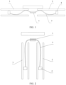
- a typical flexible circuit board test device is mainly used to test a flexible circuit board that bends with the bending of a screen in a foldable phone.
- Such a test device has a double-flap structure, with a left flap and a right flap that are hinged with each other.
- the test device can simulate unfolding and folding of a mobile phone by driving the left flap and the right flap to perform unfolding and folding actions, so as to perform a bending test on a flexible circuit board.
- a flexible circuit board sample needs to be adhered onto a pairing surface of the left flap and the right flap, with two ends of the flexible circuit board sample connected to a terminal through manual welding of wires.
- a quantity of bending times and resistance are recorded by a data acquisition and monitoring control system for further analysis and determination.
- test devices can simply simulate bending actions of flexible circuit boards due to relatively limited functions, so that such test devices cannot provide more comprehensive and accurate test data for the design of the flexible circuit boards.
- each of the test devices can only simulate one bending radius. To simulate different bending radii, different test devices are needed. In addition, such test devices cannot simulate assembly morphology of flexible circuit boards. Especially for electronic devices with relative motion scenarios such as folding and retracting among components, because flexible circuit boards will move among structural components, analysis on motion trajectory is very important, but it is difficult for such test devices to analyze motion trajectory of flexible circuit boards.
- CN 213 689 193 U provides a reliability test platform for a multifunctional flexible device, which comprises a first motion block, a second motion block, a third motion block and a mechanical property measuring device, and is characterized in that the first motion block and the second motion block are respectively used for fixing a first end and a second end of the flexible device and can linearly move along a first axis; the third moving block and the second moving block are connected through the mechanical property measuring device, and the third moving block can drive the second moving block to move linearly along the first axis.
- CN 110 296 900 A relates to a bending test equipment of a flexible sample.
- the equipment comprises at least one bearing component, the bearing component comprises a horizontal fixation part, and two movement parts rotatably connected to two sides of the horizontal fixation part; the movement parts have the movement degree of freedom of overturning up and down in relative to the horizontal fixation part.
- CN 113 358 490 A relates to a flexible material bending test device that comprises a first connecting rod, a second connecting rod, a third connecting rod, a fourth connecting rod, a first connecting shaft, a second connecting shaft, a control panel, a moving table and an operating table.
- the first connecting rod, the second connecting rod, the third connecting rod and the fourth connecting rod are identical in structure and are hinged end to end to form a parallelogram mechanism, the first connecting rod is hinged to the second connecting rod through a first connecting shaft, the third connecting rod is hinged to the fourth connecting rod through a second connecting shaft, and clamping assemblies used for clamping flexible materials are arranged on the first connecting rod and the second connecting rod.
- the second connecting shaft is rotationally arranged on the moving table, a separating and supporting assembly which is connected with the first connecting shaft and supports the flexible material between the two sets of clamping assemblies is arranged on the operating table, a lifting mechanism used for driving the moving table to ascend and descend is arranged on the operating table, and the control panel is arranged on the operating table.
- CN 107 976 372 A relates to a strength testing device, which comprises a base station, a hinging part, a first supporting element and a second supporting element, wherein the hinging part is arranged on the base station and comprises a compression bar;
- the first supporting element comprises a first supporting body, a first regulation plate arranged on the first supporting body in a sliding way and a first regulation part connected to the first supporting body and the first regulation plate;
- the second supporting element comprises a second regulation plate and a second regulation part which drives the second regulation plate to move and is arranged on the base station, the first supporting body is rotatably installed on the hinging part;
- the first regulation plate and the second regulation plate are positioned on two opposite sides of the hinging part;
- the first supporting body overturns relative to the second regulation plate by taking the compression bar as a shaft;
- the surface of the first regulation plate and the surface of the second regulation plate are respectively provided with a first positioning point and a second positioning point;
- the compression bar is positioned between the
- An embodiment of this application provides a flexible circuit board test device.
- the test device can provide more comprehensive and accurate test data for the design of a flexible circuit board.
- the flexible circuit board test device is provided with a main clamp, a first rotating shaft arm, and a second rotating shaft arm, where the main clamp is generally located at a central position of the device and is configured to locate a middle area of a flexible circuit board to be tested; the first rotating shaft arm and the second rotating shaft arm are rotatably mounted on a first mobile table and a second mobile table through a first main shaft and a second main shaft respectively; the first main shaft and the second main shaft are located on two sides of the main clamp, and the first rotating shaft arm and the second rotating shaft arm each are provided with a sandwich space for simulating a motion space of the flexible circuit board.
- a first driving component and a second driving component provide power to drive the first rotating shaft arm and the second rotating shaft arm to unfold or fold, so as to simulate an actual service state of the flexible circuit board in a product.
- a bending radius of the flexible circuit board at the main clamp may be adjusted to perform bending tests with different radii, which is compatible with actual service scenarios of most products (for example, a foldable phone), so that the development requirements of different products can be met by using only one set of test device.
- the first mobile table and the second mobile table are respectively provided with a mobile table driving mechanism, and the mobile table driving mechanism is configured to drive the first mobile table and the second mobile table to move in a horizontal plane to adjust positions of the first mobile table and the second mobile table with respect to the main clamp, so as to adjust the bending radius of the flexible circuit board, and simulate actual operating conditions of different products, thereby expanding the test range.
- the mobile table driving mechanism includes a base and an intermediate carrier; the mobile tables are mounted on the intermediate carrier through a first slide rail, and the intermediate carrier is provided with a third driving component for driving the mobile tables to move along a first direction defined by the first slide rail; and the intermediate carrier is mounted on the base through a second slide rail, and the base is provided with a fourth driving component for driving the intermediate carrier to move along a second direction defined by the second slide rail.
- the first mobile table is provided with a first frame
- the second mobile table is provided with a second frame
- the first main shaft and the second main shaft are respectively mounted on adjacent edges of the first frame and the second frame.
- the first rotating shaft arm and the second rotating shaft arm each include a base plate, and a clamping plate located on one side of a pairing surface of the base plate and connected to the base plate, the base plate of the first rotating shaft arm is connected to the first main shaft, the base plate of the second rotating shaft arm is connected to the second main shaft, and the sandwich space is formed between the clamping plate and the base plate.
- a first adjusting mechanism is disposed between the clamping plate and the base plate, and the first adjusting mechanism is configured to adjust a spacing between the clamping plate and the base plate.
- sandwich spaces with different thicknesses may be simulated, so that the thicknesses of the sandwich spaces are basically consistent with actual thicknesses of inner spaces of different products, and a test process is closer to an actual using process. Therefore, more accurate test results and data can be obtained.
- the first adjusting mechanism includes two sets of upper connecting plates and lower connecting plates located at upper edges and lower edges that are of the base plate and the clamping plate and that are on one side away from the main clamp, the upper connecting plates and the lower connecting plates are respectively provided with oblong holes perpendicular to the base plate in a length direction, the upper connecting plates are connected by an upper connector running through the oblong holes, and the lower connecting plates are connected by a lower connector running through the oblong holes.
- the first rotating shaft arm has a lateral width smaller than that of the second rotating shaft arm, upper and lower ends of the first rotating shaft arm go beyond upper and lower ends of the second rotating shaft arm; in a paired state, the upper connecting plate and the lower connecting plate of the first rotating shaft arm and the upper connecting plate and the lower connecting plate of the second rotating shaft arm are misaligned with each other.
- a second adjusting mechanism is disposed between the clamping plate and the upper connecting plate and the lower connecting plate thereof, and the second adjusting mechanism is configured to adjust an included angle between the clamping plate and the base plate, so as to simulate an included angle between a middle frame and a screen after integrated equipment is folded, thereby further enhancing test capabilities.
- the second adjusting mechanism includes: a rotating structure in which the clamping plate is connected to the upper connecting plate and the lower connecting plate thereof through an oscillating shaft; and a fifth driving component disposed at bottom of the lower connecting plate of the clamping plate, where the fifth driving component is configured to drive the clamping plate to rotate around the oscillating shaft.
- a quantity of the auxiliary clamps is more than one, and the plurality of auxiliary clamps are arranged in a vertical direction on the base plate.
- the base plate is provided with a slot for accommodating the auxiliary clamps, the plurality of auxiliary clamps are connected as a whole to form an auxiliary clamp assembly, the auxiliary clamp assembly is mounted on the base plate through a third adjusting mechanism, and the third adjusting mechanism is configured to adjust a posture of the auxiliary clamp assembly with respect to the base plate, so as to simulate different connection modes and/or lead-out modes that may exist between the flexible circuit board and other electrical components in practice.
- the third adjusting mechanism includes an upper rotating shaft and a lower rotating shaft located at upper and lower ends of the auxiliary clamp assembly, the auxiliary clamp assembly is rotatably mounted in the slot of the base plate through the upper rotating shaft and the lower rotating shaft, the lower rotating shaft is connected to an adjusting disc, and the adjusting disc is provided with a plurality of connecting holes centered on the lower rotating shaft and can be connected to the base plate through different connecting holes.
- a fourth adjusting mechanism is disposed between the auxiliary clamp assembly and the base plate, and the fourth adjusting mechanism is configured to adjust a lateral position of the auxiliary clamp assembly on the base plate. Therefore, various flexible circuit boards with different lengths may be tested, thereby further expanding the test range of the test device.
- the fourth adjusting mechanism includes sliding grooves disposed at the upper edge and the lower edge of the base plate, the upper rotating shaft and the lower rotating shaft of the third adjusting mechanism can move in a lateral direction in the sliding grooves and can be located by locating components, and a surface of the base plate is provided with a hollow area that provides a lateral movement space for the auxiliary clamp assembly.
- a frame opening corresponding to the auxiliary clamps is formed on the clamping plate.
- the auxiliary clamps are provided with an electrical connection structure, the electrical connection structure includes an electrical connection seat and an electrical connection cover that can be buckled with each other, a space for accommodating ends of the flexible circuit board is formed between the electrical connection seat and the electrical connection cover, and an inner surface of the electrical connection seat or the electrical connection cover is provided with conductive pins in contact and conduction with pads at one end of the flexible circuit board.
- the inner surface of the electrical connection seat or the electrical connection cover is provided with a locating column for locating the ends of the flexible circuit board.
- the flexible circuit board test device further includes an image acquisition device that is mounted in an area above the main clamp through a position adjusting mechanism, and the image acquisition device is configured to observe and record motion trajectory and morphology of the flexible circuit board.
- Receding structure 31. Upper rotating shaft; 32. Lower rotating shaft; 33. Adjusting disc; 34. Connecting hole; 35. Sliding groove; 36. Locating component; 37. Electrical connection seat; 38. Electrical connection cover; 39. Conductive pin; 40. Locating column; and 101. Position adjusting mechanism.
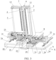
- this embodiment provides a flexible circuit board test device.
- the test device mainly includes components such as a main clamp 1, a first rotating shaft arm 2, a second rotating shaft arm 3, and auxiliary clamps 4.
- the test device simulates a motion space of a flexible circuit board in integrated equipment through the cooperation among the main clamp 1, the first rotating shaft arm 2, the second rotating shaft arm 3, and the auxiliary clamps 4.
- a semi-open structure formed therefrom allows dynamic trajectory of a flexible circuit board 5 to be visualized.
- the main clamp 1 (the mounting position of the main clamp is indicated by a central axis in the figures) is generally located in the center of the device, and is configured to locate a middle area of the flexible circuit board 5.
- the main clamp is available in different morphology and location modes, for example, the main clamp may be fixed from the middle of the flexible circuit board 5 through clamping.
- the first main shaft 6 and the second main shaft 7 are located on left side and right side of the main clamp 1, respectively.
- the first rotating shaft arm 2 is rotatably mounted on a first mobile table 8 through the first main shaft 6, and the second rotating shaft arm 3 is rotatably mounted on a second mobile table 9 through the second main shaft 7.
- the first rotating shaft arm 2 and the second rotating shaft arm 3 can rotate on the mobile tables on which the first rotating shaft arm 2 and the second rotating shaft arm 3 are respectively mounted.
- the first mobile table 8 is provided with a first frame 11
- the second mobile table 9 is provided with a second frame 12.
- the first frame 11 and the second frame 12 are rectangular frames vertically fixed on the first mobile table 8 and the second mobile table 9, and vertical side plates on two sides of the frames are trapezoidal with a narrow upper part and a wide lower part, so as to improve structural strength and stability of the frames.
- the first main shaft 6 and the second main shaft 7 are respectively mounted on adjacent sides of the first frame 11 and the second frame 12, that is, the sides close to the main clamp 1.
- the first rotating shaft arm 2 and the second rotating shaft arm 3 may be directly connected to the first main shaft 6 and the second main shaft 7, or may be indirectly connected to the first main shaft 6 and the second main shaft 7 through a connector.
- the first mobile table 8 and the second mobile table 9 are respectively provided with a first driving component 13 and a second driving component 14.
- both the first driving component 13 and the second driving component 14 are motors.
- the first driving component 13 is vertically mounted on the first mobile table 8, a power output shaft of the first driving component extends downward from the first mobile table 8, and the power output shaft of the first driving component 13 is provided with a first transmission wheel 15.
- a lower end of the first main shaft 6 runs through the first mobile table 8 and extends downward, and the lower end of the first main shaft is provided with a second transmission wheel 16.
- the first transmission wheel 15 is connected to the second transmission wheel 16 through a transmission belt 17.
- the first driving component 13 runs, the first main shaft 6 may be driven to rotate, so as to drive the first rotating shaft arm 2 to rotate.
- the second driving component 14 is vertically mounted on the second mobile table 9, a power output shaft of the second driving component extends downward from the second mobile table 9, and the power output shaft of the second driving component 14 is provided with a third transmission wheel 18.
- a lower end of the second main shaft 7 runs through the second mobile table 9 and extends downward, and the lower end of the second main shaft is provided with a fourth transmission wheel 19.
- the third transmission wheel 18 is in transmission connection with the fourth transmission wheel 19 through a transmission belt (not shown in the figures).
- the second main shaft 7 may be driven to rotate, so as to drive the second rotating shaft arm 3 to rotate.
- the first driving component 13 and the second driving component 14 may drive the first rotating shaft arm 2 and the second rotating shaft arm 3 to perform unfolding and folding actions, so as to simulate an actual service state of a product (for example, a foldable phone).
- the first mobile table 8 and the second mobile table 9 may not be on the same horizontal plane.
- the first mobile table 8 is lower than the second mobile table 9, and the two mobile tables are staggered in height, so as to avoid a structural conflict between the two mobile tables during unfolding and folding actions and subsequent adjustment.
- the first mobile table 8 and the second mobile table 9 are respectively provided with a mobile table driving mechanism, and the mobile table driving mechanisms are configured to drive the first mobile table 8 and the second mobile table 9 to move in a horizontal plane, so as to adjust positions of the two mobile tables with respect to the main clamp 1.
- the mobile table driving mechanism has a base 20 and an intermediate carrier 21, the intermediate carrier 21 is disposed parallel to the base 20, the first mobile table 8 is mounted on the intermediate carrier 21 through a first slide rail 22, the intermediate carrier 21 is provided with a third driving component 23, and the first mobile table 8 may be driven by the third driving component 23 to move in an X direction along the first slide rail 22.
- the intermediate carrier 21 is mounted on the base 20 through a second slide rail 24, the base 20 is provided with a fourth driving component 25, and the intermediate carrier 21 and the first mobile table 8 carried by the intermediate carrier may be driven by the fourth driving component 25 to move in a Y direction along the second slide rail 24.
- the mobile table driving mechanism of the second mobile table 9 is the same as the mobile table driving mechanism of the first mobile table 8 in structure, so that the two mobile table driving mechanisms may be arranged symmetrically from left to right.
- the mobile table driving mechanism of the first mobile table 8 is also lower than the mobile table driving mechanism of the second mobile table 9, which structurally reflects that the base 20 of the second mobile table 9 is higher than the base 20 of the first mobile table 8 by a distance.
- both the third driving component 23 and the fourth driving component 25 are linear motors, and the first mobile table 8 and the second mobile table 9 are provided with two third driving components 23 and two fourth driving components 25.
- motors may also be used for driving. If a motor that outputs rotary motion is used, a corresponding power conversion mechanism needs to be added to convert the rotary motion of the motor into linear motion, such as a gear and a rack mechanism.
- the mobile tables, the rotating shaft arms and the main shafts may be moved as a whole by moving the driving mechanisms. Therefore, the first main shaft 6 of the first rotating shaft arm 2 and the second main shaft 7 of the second rotating shaft arm 3 may be adjusted in the X and Y directions, so that 0.3-2.0 mm bending radii may be simulated to implement stepless adjustment of the bending radii, and perform bending tests with different radii, which is compatible with scenarios of most foldable phones, so that the development requirements of different products can be met by using only one set of device.
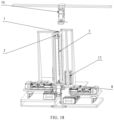
- an image acquisition device 10 is further provided.
- the image acquisition devices 10 shown in FIG. 5 and FIG. 7 are CCD cameras.
- the image acquisition device 10 is configured to observe and record motion trajectory and morphology of the flexible circuit board 5, and can capture dynamic bending morphology of the flexible circuit board 5 at different angles of the rotating shaft arms in real time, calculate a bending radius at the moment, implement functions of magnification and position movement, and detect FPC morphology at key positions.
- the image acquisition device 10 is mounted in an area above the main clamp 1 through a position adjusting mechanism 101. Observation and shooting positions of the image acquisition device 10 may be adjusted by controlling the position adjusting mechanism 101, so as to meet different test requirements.
- sandwich spaces are formed inside the first rotating shaft arm 2 and the second rotating shaft arm 3, so that a motion space of the flexible circuit board 5 may be simulated.
- the first rotating shaft arm 2 and the second rotating shaft arm 3 are provided with auxiliary clamps 4.
- auxiliary clamps 4 After the middle of the flexible circuit board 5 is located by the main clamp 1, two ends of the flexible circuit board enter the sandwich spaces of the first rotating shaft arm 2 and the second rotating shaft arm 3 respectively.
- the two ends of the flexible circuit board 5 are located by the auxiliary clamps 4, and the two ends of the flexible circuit board 5 and the auxiliary clamps 4 are electrically conductive, so as to implement electrical connection.
- the first rotating shaft arm 2 and the second rotating shaft arm 3 each have a base plate 26 and a clamping plate 27 on one side of a pairing surface of the base plate, the clamping plate 27 is connected to the base plate 26, the base plate 26 of the first rotating shaft arm 2 is connected to the first main shaft 6, and the base plate 26 of the second rotating shaft arm 3 is connected to the second main shaft 7.
- the clamping plate 27 is connected to the base plate 26, a sandwich space for simulating a motion space of the flexible circuit board 5 is formed between the clamping plate 27 and the base plate 26.
- a quantity of the auxiliary clamps 4 is more than one, and the plurality of auxiliary clamps 4 are arranged in a vertical direction on the base plate 26.
- a plurality of flexible circuit boards 5 to be tested are mounted in parallel in the sandwich spaces in a lateral posture, so that a plurality of sets of flexible circuit boards 5 may be tested at a time.
- a vertical frame opening corresponding to the auxiliary clamps 4 is formed on the clamping plate 27 to expose a part of the auxiliary clamps 4.
- the whole sandwich space is constructed as a semi-open structure, which facilitates operation, observation, and shooting when the sandwich space is highly consistent with the environment of the integrated equipment, so that the collection of test data is easier and the test data is more accurate.
- a first adjusting mechanism is disposed between the clamping plate 27 and the base plate 26, and a spacing between the clamping plate 27 and the base plate 26 may be adjusted by the first adjusting mechanism, so as to simulate sandwich spaces with different thicknesses.
- a structure of the first adjusting mechanism is as follows: An upper connecting plate 261 and a lower connecting plate 262 are disposed respectively at an upper edge and a lower edge that are of the base plate 26 and that are on one side away from the main clamp 1, and the upper connecting plate 261 and the lower connecting plate 262 are perpendicular to a surface of the base plate 26. An upper connecting plate 271 and a lower connecting plate 272 are disposed respectively at an upper edge and a lower edge that are of the clamping plate 27 and that are on one side away from the main clamp 1, and the upper connecting plate 271 and the lower connecting plate 272 are perpendicular to a surface of the clamping plate 27.
- the upper connecting plate 261 of the base plate 26 is connected to the upper connecting plate 271 of the clamping plate 27 by an upper connector
- the lower connecting plate 262 of the base plate 26 is connected to the lower connecting plate 272 of the clamping plate 27 by a lower connector.
- Both the upper connector and the lower connector may be bolts (not shown in the figure), and bolt holes on the upper connecting plates 261, 271 and the lower connecting plates 262, 272 are oblong holes perpendicular to the surface of the base plate 26 in a length direction.
- a spacing between the clamping plate 27 and the base plate 26 may be adjusted in the direction of the oblong holes, and the clamping plate 27 may be fixed at an adjusted position after the bolts are fastened again, and an adjustment range may be 0-10 mm.
- the first rotating shaft arm 2 has a lateral width smaller than that of the second rotating shaft arm 3, upper and lower ends of the first rotating shaft arm 2 go beyond upper and lower ends of the second rotating shaft arm 3.
- the upper connecting plates 261, 271 and the lower connecting plates 262, 272 of the first rotating shaft arm 2 and the upper connecting plates 261, 271 and the lower connecting plates 262, 272 of the second rotating shaft arm 3 may be misaligned with each other (as shown in FIG. 20 ), so as to avoid a structural conflict.
- a second adjusting mechanism is disposed between the clamping plate 27 and the upper connecting plate 271 and the lower connecting plate 272 thereof, and the second adjusting mechanism is configured to adjust an included angle between the clamping plate 27 and the base plate 26.
- a structure of the second adjusting mechanism will be described below by using the clamping plate 27 of the first rotating shaft arm 2 as an example.
- the clamping plate 27 is connected to the upper connecting plate 271 and the lower connecting plate 272 through an oscillating shaft 28 to form a rotatable structure, where a fifth driving component 29 is disposed at bottom of the lower connecting plate 272 of the clamping plate 27.
- the fifth driving component 29 is a motor
- the fifth driving component 29 is configured to drive the clamping plate 27 to rotate around the oscillating shaft 28.
- the clamping plate 27 of the second rotating shaft arm 3 is adjusted by using the same structure.
- the lower connecting plate 262 of the base plate 26 is provided with a receding structure 30 corresponding to the fifth driving component 29, and the receding structure 30 has a shape of a frame opening.
- the fifth driving component 29 may move in the frame opening, so as to avoid a structural conflict between the lower connecting plate 262 of the base plate 26 and the fifth driving component 29 during adjustment.
- Rotational motion of the first rotating shaft arm 2 is independent of the second rotating shaft arm 3.
- the clamping plates 27 of the first rotating shaft arm 2 and the second rotating shaft arm 3 may implement independent degrees of freedom of rotation on the basis of overall rotation, so as to simulate an included angle between a middle frame and a screen after integrated equipment is folded, thereby further enhancing test capabilities. As shown in FIG. 8 and FIG.
- the base plate 26 is provided with a slot for accommodating the auxiliary clamps 4, the plurality of auxiliary clamps 4 are connected as a whole to form an auxiliary clamp assembly, the auxiliary clamp assembly is mounted in the slot of the base plate 26 through a third adjusting mechanism, and the third adjusting mechanism is configured to adjust a posture of the auxiliary clamp assembly with respect to the base plate 26.
- the third adjusting mechanism mainly includes an upper rotating shaft 31 and a lower rotating shaft 32 located at upper and lower ends of the auxiliary clamp assembly, and the auxiliary clamp assembly is rotatably mounted in the slot of the base plate 26 through the upper rotating shaft 31 and the lower rotating shaft 32, where a lower end of the lower rotating shaft 32 is connected to an adjusting disc 33, a plurality of connecting holes 34 centered on the lower rotating shaft are formed on the adjusting disc 33, and every two connecting holes on the diagonal line are a set.
- the adjusting disc may be connected to a lower end face of the base plate 26 by using screws or bolts. When the adjusting disc is connected to the base plate 26 through different connecting holes, the auxiliary clamp assembly may be fixed at different angles.
- An angle between the auxiliary clamps 4 and the base plate 26 shown in the figures may be adjusted among -45°, 0° and +45°, so as to simulate morphology of an unfolding and folding process of the flexible circuit board 5 in different architecture spaces of the integrated equipment, for example, in a foldable phone with different rotating shaft spaces.
- the flexible circuit board 5 is generally flat after being fixed by the main clamp 1 and the auxiliary clamps 4, and two ends of the flexible circuit board are generally perpendicular to the auxiliary clamps 4.
- the flexible circuit board 5 is not completely flat, and there is a non-90° included angle between the two ends and the auxiliary clamps 4, so as to simulate different connection modes and/or lead-out modes that may exist between the flexible circuit board 5 and other electrical components in practice.
- a fourth adjusting mechanism may be further disposed between the auxiliary clamp assembly and the base plate 26, and the fourth adjusting mechanism is configured to adjust a lateral position of the auxiliary clamp assembly on the base plate 26.
- the fourth adjusting mechanism may have sliding grooves 35 disposed at the upper edge and the lower edge of the base plate 26, the upper rotating shaft 31 and the lower rotating shaft 32 of the third adjusting mechanism can move in a lateral direction in the sliding grooves 35 and can be located by locating components 36, and a surface of the base plate 26 is provided with a hollow area that provides a lateral movement space for the auxiliary clamp assembly.
- a distance between the left and right auxiliary clamps 4 may be adjusted by adjusting positions of the upper rotating shaft 31 and the lower rotating shaft 32 on the base plate 26 laterally. Therefore, various flexible circuit boards 5 with different lengths may be tested, thereby further expanding the test range of the test device.
- the auxiliary clamps 4 can locate both ends of the flexible circuit board 5, and are further provided with an electrical connection structure.
- the electrical connection structure mainly includes an electrical connection seat 37 and an electrical connection cover 38 that can be buckled with each other, a space for accommodating the ends of the flexible circuit board 5 is formed between the electrical connection seat 37 and the electrical connection cover 38, an inner surface of the electrical connection cover 38 is provided with conductive pins 39, the conductive pins 39 each have a micropin structure and correspond to pads 51 at one end of the flexible circuit board 5 one by one, and an inner surface of the electrical connection seat 37 is provided with a locating column 40 for locating the ends of the flexible circuit board 5.
- a locating hole is formed at one end of the flexible circuit board 5.
- the locating hole on the flexible circuit board 5 is aligned with the locating column 40 on the electrical connection seat 37, and put into the electrical connection seat 37.
- the electrical connection cover 38 is buckled on the electrical connection seat 37, and the flexible circuit board 5 is clamped and fixed.
- the conductive pins 39 on the inner surface of the electrical connection cover 38 are in contact with the pads 51 at the end of the flexible circuit board 5 to implement electrical conduction.
- the two ends of the flexible circuit board 5 are electrified through the conductive pins 39 of the auxiliary clamps 4 without manual welding of wires, which saves device space.
- the flexible circuit board 5 is designed with good compatibility. During a dynamic bending test of the flexible circuit board 5, the flexible circuit board 5 is powered on throughout the test, and resistance changes are recorded. If resistance of the flexible circuit board 5 increases or in case of open circuit, the test may be automatically suspended, and the morphology, the quantity of bending times, and the bending angle of the flexible circuit board 5 at this time are recorded to complete a life test of the flexible circuit board 5.
- the flexible circuit board test device for the flexible circuit board test device provided in this application, by simulating the motion space of the flexible circuit board 5 through the sandwich spaces formed inside the first rotating shaft arm 2 and the second rotating shaft arm 3, actual assembly morphology and motion trajectory of the flexible circuit board 5 may be tested, so as to provide more comprehensive and accurate test data for the design of the flexible circuit board 5.
- the mobile tables on two sides of the main clamp 1 can be driven by the driving components to move, and positions of the first rotating shaft arm 2 and the second rotating shaft arm 3 with respect to the main clamp 1 may be adjusted. Therefore, a bending radius of the flexible circuit board 5 may be adjusted to perform bending tests with different radii, which is compatible with actual service scenarios of most products (for example, a foldable phone).
- Test item 1
- bending tests with tens of thousands of times of bending are carried out at different bending radii to determine whether there is failure or minor damage.
- different bending radii may be 0.30 mm, 0.45 mm, 0.60 mm, and 1.0 mm.
- the optimal design scheme for the flexible circuit board 5 under different bending radii, different lengths of flexible circuit boards and other parameters may be assessed by adjusting device parameters to find the optimal solution to product design.
- Ten flexible circuit boards 5 are tested at a time, and bending tests with tens of thousands of times of bending are carried out. Circuit resistance of the flexible circuit boards 5 is detected and recorded. If the resistance increases by 10%, it is determined that the flexible circuit boards have failed. A quantity of bending times and bending angles of the flexible circuit boards 5 at this time are recorded.
- this test is used to analyze a bending performance baseline of the flexible circuit board 5 in the current design scheme. Through failure analysis on a single failed flexible circuit board 5, a failure location can be found, so as to optimize the design.
- One flexible circuit board 5 is tested at a time, and bending tests with tens of thousands of times (for example, 50,000 times) of bending are carried out. After bending tests with 5,000/10,000/20,000/50,000 times of bending, the bending morphology of the flexible circuit board 5 at 0°/30°/45°/90° is detected, and the bending radius is measured.
- This test item may be used to test whether the bending radius of the flexible circuit board 5 meets a requirement and whether there are potential risks. This test item may also be used to test morphological consistency of the flexible circuit board 5 after repeated bending.
- the morphology of the flexible circuit board 5 in a 180° static bending scenario is simulated: After the first rotating shaft arm 2 and the second rotating shaft arm 3 are folded, the flexible circuit board 5 is bent to the maximum extent, the main clamp 1 releases the flexible circuit board 5, and the auxiliary clamps 4 fix both ends of the flexible circuit board 5 to simulate the morphology of the flexible circuit board 5 in a 180° bending scenario.
- the main clamp is used to simulate a bending area space, and the auxiliary clamps are used to control drop and a length of the flexible circuit board 5.
- the forgoing embodiment is merely a preferred solution of this application, and is not specifically limited thereto. Based on this solution, a targeted adjustment may be made based on an actual requirement, to obtain different implementations. For example, the base plate 26 and the clamping plate 27 are mutually connected by other means, or the conductive pins 39 in the electrical connection structure of the auxiliary clamps 4 are migrated to the electrical connection seat 37 (as shown in FIG. 16 ). Because there are many possible implementations, examples are not described herein again.
- the bending life test for the flexible circuit board 5 may be carried out in advance, and the test may be carried out independent of complete materials such as structural members and rotating shafts of the integrated equipment. Reliability issues arouse ahead of product development, risks are identified in advance, so that design changes associated with rotating shafts of the flexible circuit board 5 are reduced, product development cost is reduced, test items are centralized, performance test related to the flexible circuit board 5 is focused, thereby eliminating the problem of early termination of the test caused by other product problems is eliminated, and effectively avoiding risks.
Landscapes
- Physics & Mathematics (AREA)
- General Physics & Mathematics (AREA)
- Analytical Chemistry (AREA)
- Health & Medical Sciences (AREA)
- Life Sciences & Earth Sciences (AREA)
- Chemical & Material Sciences (AREA)
- Biochemistry (AREA)
- General Health & Medical Sciences (AREA)
- Immunology (AREA)
- Pathology (AREA)
- Engineering & Computer Science (AREA)
- General Engineering & Computer Science (AREA)
- Microelectronics & Electronic Packaging (AREA)
- Computer Hardware Design (AREA)
- Tests Of Electronic Circuits (AREA)
Claims (14)
- Testvorrichtung für flexible Leiterplatten, umfassend:eine Hauptklemme (1), die konfiguriert ist, um einen mittleren Bereich einer flexiblen Leiterplatte (5) zu positionieren;einen ersten rotierenden Wellenarm (2) und einen zweiten rotierenden Wellenarm (3); wobei der erste rotierende Wellenarm (2) und der zweite rotierende Wellenarm (3) auf einem ersten mobilen Tisch (8) und einem zweiten mobilen Tisch (9) über eine erste Hauptwelle (6) bzw. eine zweite Hauptwelle (7) rotierbar montiert sind; sich die erste Hauptwelle (6) bzw. die zweite Hauptwelle (7) auf zwei Seiten der Hauptklemme (1) befinden; der erste rotierende Wellenarm (2) und der zweite rotierende Wellenarm (3) jeweils mit einem Sandwichraum zum Simulieren eines Bewegungsraums der flexiblen Leiterplatte (5) versehen sind; und der erste mobile Tisch (8) mit einer ersten Antriebskomponente (13) versehen ist, die in Übertragungsverbindung mit der ersten Hauptwelle (6) steht, der zweite mobile Tisch (9) mit einer zweiten Antriebskomponente (14) versehen ist, die in Übertragungsverbindung mit der zweiten Hauptwelle (7) steht, und die erste Antriebskomponente (13) und die zweite Antriebskomponente (14) konfiguriert sind, um den ersten rotierenden Wellenarm (2) und den zweiten rotierenden Wellenarm (3) anzutreiben, um Ausklapp- und Einklappaktionen durchzuführen; undder erste rotierende Wellenarm (2) und der zweite rotierende Wellenarm (3) jeweils mit Hilfsklemmen (4) in den Sandwichräumen versehen sind, und die Hilfsklemmen (4) konfiguriert sind, um zwei Enden der flexiblen Leiterplatte (5) zu lokalisieren, die in den Sandwichraum eintreten, und elektrisch mit der flexiblen Leiterplatte (5) verbunden sind, wobei der erste mobile Tisch (8) und der zweite mobile Tisch (9) jeweils mit einem Antriebsmechanismus für den mobilen Tisch versehen sind, und der Antriebsmechanismus für den mobilen Tisch konfiguriert ist, um den ersten mobilen Tisch (8) und den zweiten mobilen Tisch (9) anzutreiben, um sich in einer horizontalen Ebene zu bewegen, um Positionen des ersten mobilen Tisches (8) und des zweiten mobilen Tisches (9) in Bezug auf die Hauptklemme (1) einzustellen.
- Testvorrichtung für flexible Leiterplatten nach Anspruch 1, wobei der Antriebsmechanismus des mobilen Tisches eine Basis (20) und einen Zwischenträger (21) umfasst; und der erste und der zweite mobile Tisch über eine erste Gleitschiene (22) auf dem Zwischenträger (21) montiert, und der Zwischenträger (21) mit einer dritten Antriebskomponente (23) versehen ist, zum Antreiben des ersten und des zweiten mobilen Tisches, um sich entlang einer ersten Richtung zu bewegen, die durch die erste Gleitschiene (22) definiert ist; und
der Zwischenträger (21) über eine zweite Gleitschiene (24) auf der Basis (20) montiert ist, und die Basis (20) mit einer vierten Antriebskomponente (25) versehen ist, zum Antreiben des Zwischenträgers (21), um sich entlang einer zweiten Richtung zu bewegen, die durch die zweite Gleitschiene (24) definiert ist. - Testvorrichtung für flexible Leiterplatten nach Anspruch 1, wobei der erste mobile Tisch (8) mit einem ersten Rahmen (11) versehen ist, der zweite mobile Tisch (9) mit einem zweiten Rahmen (12) versehen ist und die erste Hauptwelle (6) und die zweite Hauptwelle (7) jeweils auf angrenzenden Kanten des ersten Rahmens (11) und des zweiten Rahmens (12) montiert sind.
- Testvorrichtung für flexible Leiterplatten nach Anspruch 1, wobei der erste rotierende Wellenarm (2) und der zweite rotierende Wellenarm (3) jeweils eine Basisplatte (26) und eine Klemmplatte (27) umfassen, die sich auf einer Seite einer Paarungsoberfläche der Basisplatte (26) befindet und mit der Basisplatte (26) verbunden ist, wobei die Basisplatte (26) des ersten rotierenden Wellenarms (2) mit der ersten Hauptwelle (6) verbunden ist, die Basisplatte (26) des zweiten rotierenden Wellenarms (3) mit der zweiten Hauptwelle (7) verbunden ist und der Sandwichraum zwischen der Klemmplatte (27) und der Basisplatte (26) ausgebildet ist.
- Testvorrichtung für flexible Leiterplatten nach Anspruch 4, wobei ein erster Einstellmechanismus zwischen der Klemmplatte (27) und der Basisplatte (26) eingerichtet ist und der erste Einstellmechanismus konfiguriert ist, um einen Abstand der Klemmplatte (27) in Bezug auf die Basisplatte (26) einzustellen.
- Testvorrichtung für flexible Leiterplatten nach Anspruch 5, wobei der erste Einstellmechanismus zwei Sätze von oberen Verbindungsplatten (261) und unteren Verbindungsplatten (262) umfasst, die an oberen Kanten und unteren Kanten der Basisplatte (26) und der Klemmplatte (27) eingerichtet sind und sich auf einer von der Hauptklemme (1) weg weisenden Seite befinden, wobei die oberen Verbindungsplatten (261) und die unteren Verbindungsplatten (262) jeweils mit Langlöchern versehen sind, die in einer Längenrichtung senkrecht zu der Basisplatte (26) verlaufen, wobei die oberen Verbindungsplatten (261) durch einen oberen Verbinder verbunden sind, der durch die Langlöcher verläuft, und wobei die unteren Verbindungsplatten (262) durch einen unteren Verbinder verbunden sind, der durch die Langlöcher verläuft.
- Testvorrichtung für flexible Leiterplatten nach Anspruch 6, wobei der erste rotierende Wellenarm (2) eine kleinere seitliche Breite als der zweite rotierende Wellenarm (3) aufweist und die oberen und unteren Enden des ersten rotierenden Wellenarms (2) über die oberen und unteren Enden des zweiten rotierenden Wellenarms (3) hinausragen; und in einem gepaarten Zustand, die obere Verbindungsplatte (261) und die untere Verbindungsplatte (262) des ersten rotierenden Wellenarms (2) und die obere Verbindungsplatte (261) und die untere Verbindungsplatte (262) des zweiten rotierenden Wellenarms (3) miteinander fehlausgerichtet sind.
- Testvorrichtung für flexible Leiterplatten nach Anspruch 6, wobei ein zweiter Einstellmechanismus zwischen der Klemmplatte (27) und der oberen Verbindungsplatte (271) und der unteren Verbindungsplatte (272) davon eingerichtet ist, und der zweite Einstellmechanismus konfiguriert ist, um einen eingeschlossenen Winkel zwischen der Klemmplatte (27) und der Basisplatte (26) einzustellen.
- Testvorrichtung für flexible Leiterplatten nach Anspruch 8, wobei der zweite Einstellmechanismus eine rotierende Struktur umfasst, in der die Klemmplatte (27) durch eine oszillierende Welle (28) mit der oberen Verbindungsplatte (271) und der unteren Verbindungsplatte (272) davon verbunden ist; und eine fünfte Antriebskomponente (29), die an der Unterseite der unteren Verbindungsplatte (272) der Klemmplatte (27) eingerichtet ist, wobei die fünfte Antriebskomponente (29) konfiguriert ist, um die Klemmplatte (27) anzutreiben, um um die oszillierende Welle (28) zu rotieren.
- Testvorrichtung für flexible Leiterplatten nach Anspruch 8, wobei eine Anzahl der Hilfsklemmen (4) größer als eins ist und die Vielzahl von Hilfsklemmen (4) in einer vertikalen Richtung auf der Basisplatte (26) eingerichtet ist.
- Testvorrichtung für flexible Leiterplatten nach Anspruch 10, wobei die Basisplatte (26) mit einem Schlitz zum Aufnehmen der Hilfsklemmen (4) versehen ist, die Vielzahl von Hilfsklemmen (4) als ein Ganzes verbunden sind, um eine Hilfsklemmenanordnung auszubilden, die Hilfsklemmenanordnung durch einen dritten Einstellmechanismus auf der Basisplatte (26) montiert ist und der dritte Einstellmechanismus konfiguriert ist, um die Hilfsklemmenanordnung zu rotieren, um eine Haltung der Hilfsklemmenanordnung in Bezug auf die Basisplatte (26) einzustellen.
- Testvorrichtung für flexible Leiterplatten nach Anspruch 11, wobei der dritte Einstellmechanismus eine obere Rotationswelle (31) und eine untere Rotationswelle (32) umfasst, die sich an den oberen und unteren Enden der Hilfsklemmanordnung befinden, die Hilfsklemmanordnung durch die obere Rotationswelle (31) und die untere Rotationswelle (32) in dem Schlitz der Basisplatte (26) rotierbar montiert ist, die untere Rotationswelle (32) mit einer Einstellscheibe (33) verbunden ist und die Einstellscheibe (3) mit einer Vielzahl von Verbindungslöchern (34) versehen ist, die auf der unteren Rotationswelle (32) zentriert ist, und durch verschiedene Verbindungslöcher (34) mit der Basisplatte (26) verbunden werden kann.
- Testvorrichtung für flexible Leiterplatten nach Anspruch 11, wobei ein vierter Einstellmechanismus zwischen der Hilfsklemmanordnung und der Basisplatte (26) eingerichtet ist und der vierte Einstellmechanismus konfiguriert ist, um die Hilfsklemmanordnung seitlich zu bewegen, um eine seitliche Position der Hilfsklemmanordnung auf der Basisplatte (26) einzustellen.
- Testvorrichtung für flexible Leiterplatten nach Anspruch 13, wobei der vierte Einstellmechanismus Gleitnuten (35) umfasst, die an der oberen Kante und der unteren Kante der Basisplatte (26) eingerichtet sind, wobei sich die obere Rotationswelle (31) und die untere Rotationswelle (32) des dritten Einstellmechanismus in den Gleitnuten (35) in einer seitlichen Richtung bewegen können und durch Positionierungskomponenten (36) positioniert werden können, und eine Oberfläche der Basisplatte (26) mit einem hohlen Bereich versehen ist, der einen seitlichen Bewegungsraum für die Hilfsklemmenanordnung bereitstellt.
Applications Claiming Priority (2)
| Application Number | Priority Date | Filing Date | Title |
|---|---|---|---|
| CN202111113658.XA CN113567275B (zh) | 2021-09-23 | 2021-09-23 | 一种柔性电路板测试设备 |
| PCT/CN2022/113578 WO2023045652A1 (zh) | 2021-09-23 | 2022-08-19 | 一种柔性电路板测试设备 |
Publications (3)
| Publication Number | Publication Date |
|---|---|
| EP4177591A1 EP4177591A1 (de) | 2023-05-10 |
| EP4177591A4 EP4177591A4 (de) | 2023-12-06 |
| EP4177591B1 true EP4177591B1 (de) | 2025-02-12 |
Family
ID=78174041
Family Applications (1)
| Application Number | Title | Priority Date | Filing Date |
|---|---|---|---|
| EP22808572.6A Active EP4177591B1 (de) | 2021-09-23 | 2022-08-19 | Testvorrichtung für flexible leiterplatte |
Country Status (4)
| Country | Link |
|---|---|
| US (1) | US12265118B2 (de) |
| EP (1) | EP4177591B1 (de) |
| CN (1) | CN113567275B (de) |
| WO (1) | WO2023045652A1 (de) |
Families Citing this family (12)
| Publication number | Priority date | Publication date | Assignee | Title |
|---|---|---|---|---|
| CN113567275B (zh) * | 2021-09-23 | 2021-12-17 | 深圳荣耀智能机器有限公司 | 一种柔性电路板测试设备 |
| CN115389351A (zh) * | 2022-09-01 | 2022-11-25 | 南方科技大学 | 测试装置以及对fpc进行性能测试的方法 |
| CN116593317A (zh) * | 2023-03-22 | 2023-08-15 | 深圳艾利门特科技有限公司 | 一种扭力检测装置 |
| CN117148121B (zh) * | 2023-10-31 | 2024-01-26 | 深圳市华旭达精密电路科技有限公司 | 一种柔性线路板电测装置 |
| CN117250207B (zh) * | 2023-11-17 | 2024-01-30 | 四川睿杰鑫电子股份有限公司 | 一种柔性电路板检测装置及检查方法 |
| CN117969306B (zh) * | 2024-03-29 | 2024-06-07 | 深圳市凌航达电子有限公司 | 一种印刷电路板用检测系统 |
| CN119231285B (zh) * | 2024-09-26 | 2025-10-14 | 苏州元脑智能科技有限公司 | 一种拆解机构及方法 |
| CN119178989B (zh) * | 2024-11-25 | 2025-04-25 | 苏州嘉财电子有限公司 | 一种基于多次检测的柔性电路板缺陷检测方法 |
| CN119738293B (zh) * | 2024-11-28 | 2025-10-17 | 昆山丘钛微电子科技股份有限公司 | 一种用于柔性电路板内部铜线使用寿命的分析方法、设备及介质 |
| CN119414215B (zh) * | 2025-01-07 | 2025-04-29 | 深圳市鑫科拓威科技有限公司 | 电路板生产线路测试装置 |
| CN119716495B (zh) * | 2025-02-27 | 2025-06-13 | 常州固堡电子有限公司 | 一种柔性线路板检测装置 |
| CN120232482B (zh) * | 2025-05-29 | 2025-08-01 | 南通江海储能技术有限公司 | 一种提升电容成组一致性的检测装置 |
Citations (1)
| Publication number | Priority date | Publication date | Assignee | Title |
|---|---|---|---|---|
| CN111089789A (zh) * | 2020-02-15 | 2020-05-01 | 四川湛海科技有限公司 | 一种用于oled屏幕测试弯折机 |
Family Cites Families (49)
| Publication number | Priority date | Publication date | Assignee | Title |
|---|---|---|---|---|
| JPS63314441A (ja) * | 1987-06-17 | 1988-12-22 | Fujikura Ltd | フレキシブルプリント配線板の屈曲試験方法 |
| CA2217591C (en) * | 1997-10-07 | 2003-07-29 | 700674 Ontario Limited, Doing Business As Carroll Associates | Wireless test fixture |
| JP3703423B2 (ja) * | 2001-10-18 | 2005-10-05 | ヒロセ電機株式会社 | フレキシブル回路基板接続装置 |
| FR2899969B1 (fr) * | 2006-04-18 | 2008-07-18 | St Microelectronics Sa | Dispositif de flexion quatre points |
| CN101329364A (zh) * | 2008-07-18 | 2008-12-24 | 中国人民解放军空军装备研究院地面防空装备研究所 | 旋转式柔性电路板测试夹具 |
| KR101295887B1 (ko) * | 2010-04-13 | 2013-08-12 | 한국전자통신연구원 | 플렉서블 소자의 벤딩 테스트 설비 |
| CN202183025U (zh) * | 2011-07-11 | 2012-04-04 | 武汉荣耀智能科技有限责任公司 | 一种智能化市电控制器 |
| CN103487710B (zh) * | 2012-06-13 | 2016-09-28 | 易鼎股份有限公司 | 电路测试震动装置 |
| US8902606B2 (en) * | 2012-10-17 | 2014-12-02 | Microelectronics Assembly Technologies | Electronic interconnect system |
| JP2014130048A (ja) * | 2012-12-28 | 2014-07-10 | Nippon Steel & Sumikin Chemical Co Ltd | フレキシブル回路基板の耐折り曲げ性試験装置および方法 |
| KR20140088356A (ko) * | 2013-01-02 | 2014-07-10 | 이종혁 | 풍력발전 전기자동차 및 충전량표시 |
| KR102124403B1 (ko) * | 2013-08-02 | 2020-06-19 | 삼성디스플레이 주식회사 | 플렉서블 디바이스의 테스트 장치 |
| US9443819B2 (en) * | 2014-02-13 | 2016-09-13 | Apple Inc. | Clamping mechanism for processing of a substrate within a substrate carrier |
| US9784656B2 (en) * | 2014-03-10 | 2017-10-10 | Cool Clubs, LLC | Methods and apparatus for measuring properties of a cantilevered member |
| KR20160125757A (ko) * | 2015-04-22 | 2016-11-01 | 충남대학교산학협력단 | 유연 기판의 신뢰성 테스트 장치 |
| KR102430787B1 (ko) * | 2015-05-29 | 2022-08-10 | 엘지디스플레이 주식회사 | 벤더블 디스플레이 |
| KR101777792B1 (ko) * | 2016-06-30 | 2017-09-12 | 울산과학기술원 | 유연소자의 신뢰성 평가 시험장치 |
| TWM552596U (zh) * | 2017-03-05 | 2017-12-01 | Iboson Technology Co Ltd | 擬真可撓式基材彎曲測試系統 |
| KR20190010809A (ko) * | 2017-07-21 | 2019-01-31 | 주식회사 이노테크 | 플렉서블 디스플레이의 벤딩 시험 장치 |
| CN207385772U (zh) * | 2017-08-22 | 2018-05-22 | 江苏荣耀电气有限公司 | 聚酰亚胺薄膜制备用涂布机 |
| KR102017564B1 (ko) * | 2017-09-11 | 2019-10-21 | 명지대학교 산학협력단 | 플렉서블 필름용 폴딩테스트 장치 |
| CN107884283B (zh) * | 2017-10-25 | 2020-05-12 | 武汉华星光电半导体显示技术有限公司 | 一种柔性oled弯折测试装置 |
| CN107976372B (zh) * | 2017-11-13 | 2021-03-02 | 武汉华星光电半导体显示技术有限公司 | 强度测试装置 |
| CN207516162U (zh) * | 2017-12-11 | 2018-06-19 | 东莞市维垦电子科技有限公司 | 一种柔性电路板测试主板检测装置 |
| KR102086705B1 (ko) * | 2018-05-14 | 2020-03-09 | 주식회사 제이이노텍 | 스트레스 테스트 장치 |
| CN109142112A (zh) * | 2018-08-31 | 2019-01-04 | 北京玛尔斯精密设备有限公司 | 一种柔性材料弯折测试装置 |
| KR102506427B1 (ko) * | 2018-09-04 | 2023-03-08 | 삼성디스플레이 주식회사 | 전자 장치 |
| CN109406319B (zh) * | 2018-11-20 | 2024-07-26 | 高德(苏州)电子有限公司 | 一种半柔性线路板的自动弯折测试设备 |
| CN208937318U (zh) * | 2018-12-12 | 2019-06-04 | 京东方科技集团股份有限公司 | 一种弯折测试装置 |
| KR102145682B1 (ko) * | 2019-02-18 | 2020-08-18 | 삼익에프에이 주식회사 | 디스플레이 폴딩기계의 스톱퍼장치 |
| KR102101287B1 (ko) * | 2019-02-18 | 2020-05-15 | 삼익에프에이(주) | 디스플레이 폴딩장치 |
| CN209961613U (zh) * | 2019-05-20 | 2020-01-17 | 浙江兆龙互连科技股份有限公司 | 一种双向动态弯曲测试装置 |
| CN110208111B (zh) * | 2019-06-10 | 2021-11-16 | 北京驳凡科技有限公司 | 一种柔性屏及膜材的弯折测试设备及其工作方法 |
| CN110296900A (zh) * | 2019-06-29 | 2019-10-01 | 昆山国显光电有限公司 | 一种柔性样品的弯折测试设备 |
| CN210488529U (zh) * | 2019-12-09 | 2020-05-08 | 天通吉成机器技术有限公司 | 一种用于绑定柔性面板的固定对位装置 |
| CN110895226B (zh) * | 2019-12-19 | 2025-01-10 | 南方电网电力科技股份有限公司 | 一种超导带材测试用装置 |
| CN111289387A (zh) * | 2020-03-24 | 2020-06-16 | 远东电缆有限公司 | 中高压风电电缆的滑移测试方法 |
| CN212159397U (zh) * | 2020-04-08 | 2020-12-15 | Oppo广东移动通信有限公司 | 柔性屏测试装置及设备 |
| CN212206937U (zh) * | 2020-04-09 | 2020-12-22 | 松山湖材料实验室 | 柔性产品弯曲循环测试设备 |
| CN213181066U (zh) * | 2020-07-31 | 2021-05-11 | 高德(苏州)电子有限公司 | 一种改进的半柔性线路板的自动弯折测试设备 |
| CN112198064B (zh) * | 2020-08-17 | 2024-05-07 | 苏州华兴源创科技股份有限公司 | 一种柔性屏弯折测试装置及测试方法 |
| CN213213973U (zh) * | 2020-09-11 | 2021-05-14 | 泗阳富朋特电子科技有限公司 | 一种用于柔性电路板折弯加工的装置 |
| CN112362476A (zh) * | 2020-11-12 | 2021-02-12 | 浙江清华柔性电子技术研究院 | 柔性器件测量系统 |
| CN213689193U (zh) * | 2020-11-12 | 2021-07-13 | 浙江清华柔性电子技术研究院 | 多功能柔性器件可靠性测试平台 |
| CN112945773B (zh) * | 2021-01-30 | 2023-11-21 | 中国科学院重庆绿色智能技术研究院 | 一种用于笔记本电脑柔性线路板生产的测试工装 |
| CN112504823B (zh) * | 2021-02-04 | 2021-05-28 | 浙江荷清柔性电子技术有限公司 | 柔性芯片弯曲能力测试装置、测试方法及柔性载具 |
| CN114953403A (zh) * | 2021-02-18 | 2022-08-30 | 中兴通讯股份有限公司 | 柔性电路板的热成型装置及方法 |
| CN113358490A (zh) * | 2021-06-24 | 2021-09-07 | 黄山学院 | 一种柔性材料弯折测试装置 |
| CN113567275B (zh) * | 2021-09-23 | 2021-12-17 | 深圳荣耀智能机器有限公司 | 一种柔性电路板测试设备 |
-
2021
- 2021-09-23 CN CN202111113658.XA patent/CN113567275B/zh active Active
-
2022
- 2022-08-19 WO PCT/CN2022/113578 patent/WO2023045652A1/zh not_active Ceased
- 2022-08-19 EP EP22808572.6A patent/EP4177591B1/de active Active
- 2022-08-19 US US18/008,378 patent/US12265118B2/en active Active
Patent Citations (1)
| Publication number | Priority date | Publication date | Assignee | Title |
|---|---|---|---|---|
| CN111089789A (zh) * | 2020-02-15 | 2020-05-01 | 四川湛海科技有限公司 | 一种用于oled屏幕测试弯折机 |
Also Published As
| Publication number | Publication date |
|---|---|
| CN113567275A (zh) | 2021-10-29 |
| EP4177591A1 (de) | 2023-05-10 |
| WO2023045652A1 (zh) | 2023-03-30 |
| CN113567275B (zh) | 2021-12-17 |
| US20240192264A1 (en) | 2024-06-13 |
| US12265118B2 (en) | 2025-04-01 |
| EP4177591A4 (de) | 2023-12-06 |
Similar Documents
| Publication | Publication Date | Title |
|---|---|---|
| EP4177591B1 (de) | Testvorrichtung für flexible leiterplatte | |
| KR101527815B1 (ko) | 폴더블 디스플레이 접힘검사장치 및 이를 이용한 접힘검사방법 | |
| KR101843874B1 (ko) | 플렉시블소재 내구성 평가용 폴딩장치 | |
| CN106841990B (zh) | 显示屏检测装置 | |
| CN218767179U (zh) | 一种耐压测试装置 | |
| CN219799667U (zh) | 多机器人协作主板测试装置 | |
| CN220305017U (zh) | 一种折叠屏手机形变测试机构 | |
| CN206515370U (zh) | 电路板测试装置 | |
| CN210954093U (zh) | 自动化测试装置 | |
| CN215448416U (zh) | 一种投影成像装置及镜头mtf测试设备 | |
| CN208334435U (zh) | 一种自动化双工位测试装置 | |
| JP7371885B2 (ja) | 電気検査装置及び保持ユニット | |
| CN211292630U (zh) | 线路板自动换位检测装置 | |
| CN219417543U (zh) | 一种低成本电路板阻抗电压测试装置 | |
| CN208422354U (zh) | 模组自动点灯治具载台 | |
| CN111024989B (zh) | 一种改进型hdi线路板高效测试针床 | |
| CN115508233A (zh) | Fpc弯折寿命及电气性能检测装置 | |
| CN222356442U (zh) | 高低温环境摄像头测试装置 | |
| CN104049114A (zh) | 电子器件量测治具及量测装置 | |
| CN222579468U (zh) | 一种姿态可调与接触力感知检测平台 | |
| CN221506732U (zh) | 电子产品功能测试平台 | |
| CN217276665U (zh) | 一种推拉力计检定装置 | |
| CN223784387U (zh) | 一种阻值检测机构及阻值检测设备 | |
| CN223597356U (zh) | 一种紧凑型电子式环境耦合应力腐蚀试验机 | |
| CN223361725U (zh) | 一种led显示屏测试装置 |
Legal Events
| Date | Code | Title | Description |
|---|---|---|---|
| STAA | Information on the status of an ep patent application or granted ep patent |
Free format text: STATUS: UNKNOWN |
|
| STAA | Information on the status of an ep patent application or granted ep patent |
Free format text: STATUS: THE INTERNATIONAL PUBLICATION HAS BEEN MADE |
|
| PUAI | Public reference made under article 153(3) epc to a published international application that has entered the european phase |
Free format text: ORIGINAL CODE: 0009012 |
|
| STAA | Information on the status of an ep patent application or granted ep patent |
Free format text: STATUS: REQUEST FOR EXAMINATION WAS MADE |
|
| 17P | Request for examination filed |
Effective date: 20221129 |
|
| AK | Designated contracting states |
Kind code of ref document: A1 Designated state(s): AL AT BE BG CH CY CZ DE DK EE ES FI FR GB GR HR HU IE IS IT LI LT LU LV MC MK MT NL NO PL PT RO RS SE SI SK SM TR |
|
| A4 | Supplementary search report drawn up and despatched |
Effective date: 20231106 |
|
| RIC1 | Information provided on ipc code assigned before grant |
Ipc: G01N 3/20 20060101ALI20231030BHEP Ipc: G01N 3/04 20060101ALI20231030BHEP Ipc: G01N 3/02 20060101ALI20231030BHEP Ipc: G01N 3/32 20060101AFI20231030BHEP |
|
| STAA | Information on the status of an ep patent application or granted ep patent |
Free format text: STATUS: EXAMINATION IS IN PROGRESS |
|
| 17Q | First examination report despatched |
Effective date: 20240502 |
|
| GRAP | Despatch of communication of intention to grant a patent |
Free format text: ORIGINAL CODE: EPIDOSNIGR1 |
|
| STAA | Information on the status of an ep patent application or granted ep patent |
Free format text: STATUS: GRANT OF PATENT IS INTENDED |
|
| DAV | Request for validation of the european patent (deleted) | ||
| DAX | Request for extension of the european patent (deleted) | ||
| INTG | Intention to grant announced |
Effective date: 20240906 |
|
| GRAS | Grant fee paid |
Free format text: ORIGINAL CODE: EPIDOSNIGR3 |
|
| GRAA | (expected) grant |
Free format text: ORIGINAL CODE: 0009210 |
|
| STAA | Information on the status of an ep patent application or granted ep patent |
Free format text: STATUS: THE PATENT HAS BEEN GRANTED |
|
| AK | Designated contracting states |
Kind code of ref document: B1 Designated state(s): AL AT BE BG CH CY CZ DE DK EE ES FI FR GB GR HR HU IE IS IT LI LT LU LV MC MK MT NL NO PL PT RO RS SE SI SK SM TR |
|
| REG | Reference to a national code |
Ref country code: GB Ref legal event code: FG4D |
|
| REG | Reference to a national code |
Ref country code: CH Ref legal event code: EP |
|
| REG | Reference to a national code |
Ref country code: DE Ref legal event code: R096 Ref document number: 602022010620 Country of ref document: DE |
|
| REG | Reference to a national code |
Ref country code: IE Ref legal event code: FG4D Ref country code: NL Ref legal event code: FP |
|
| PG25 | Lapsed in a contracting state [announced via postgrant information from national office to epo] |
Ref country code: RS Free format text: LAPSE BECAUSE OF FAILURE TO SUBMIT A TRANSLATION OF THE DESCRIPTION OR TO PAY THE FEE WITHIN THE PRESCRIBED TIME-LIMIT Effective date: 20250512 |
|
| PG25 | Lapsed in a contracting state [announced via postgrant information from national office to epo] |
Ref country code: FI Free format text: LAPSE BECAUSE OF FAILURE TO SUBMIT A TRANSLATION OF THE DESCRIPTION OR TO PAY THE FEE WITHIN THE PRESCRIBED TIME-LIMIT Effective date: 20250212 |
|
| PG25 | Lapsed in a contracting state [announced via postgrant information from national office to epo] |
Ref country code: PL Free format text: LAPSE BECAUSE OF FAILURE TO SUBMIT A TRANSLATION OF THE DESCRIPTION OR TO PAY THE FEE WITHIN THE PRESCRIBED TIME-LIMIT Effective date: 20250212 |
|
| PG25 | Lapsed in a contracting state [announced via postgrant information from national office to epo] |
Ref country code: ES Free format text: LAPSE BECAUSE OF FAILURE TO SUBMIT A TRANSLATION OF THE DESCRIPTION OR TO PAY THE FEE WITHIN THE PRESCRIBED TIME-LIMIT Effective date: 20250212 |
|
| REG | Reference to a national code |
Ref country code: LT Ref legal event code: MG9D |
|
| PG25 | Lapsed in a contracting state [announced via postgrant information from national office to epo] |
Ref country code: IS Free format text: LAPSE BECAUSE OF FAILURE TO SUBMIT A TRANSLATION OF THE DESCRIPTION OR TO PAY THE FEE WITHIN THE PRESCRIBED TIME-LIMIT Effective date: 20250612 Ref country code: NO Free format text: LAPSE BECAUSE OF FAILURE TO SUBMIT A TRANSLATION OF THE DESCRIPTION OR TO PAY THE FEE WITHIN THE PRESCRIBED TIME-LIMIT Effective date: 20250512 |
|
| PG25 | Lapsed in a contracting state [announced via postgrant information from national office to epo] |
Ref country code: HR Free format text: LAPSE BECAUSE OF FAILURE TO SUBMIT A TRANSLATION OF THE DESCRIPTION OR TO PAY THE FEE WITHIN THE PRESCRIBED TIME-LIMIT Effective date: 20250212 |
|
| PG25 | Lapsed in a contracting state [announced via postgrant information from national office to epo] |
Ref country code: LV Free format text: LAPSE BECAUSE OF FAILURE TO SUBMIT A TRANSLATION OF THE DESCRIPTION OR TO PAY THE FEE WITHIN THE PRESCRIBED TIME-LIMIT Effective date: 20250212 Ref country code: PT Free format text: LAPSE BECAUSE OF FAILURE TO SUBMIT A TRANSLATION OF THE DESCRIPTION OR TO PAY THE FEE WITHIN THE PRESCRIBED TIME-LIMIT Effective date: 20250612 |
|
| PG25 | Lapsed in a contracting state [announced via postgrant information from national office to epo] |
Ref country code: GR Free format text: LAPSE BECAUSE OF FAILURE TO SUBMIT A TRANSLATION OF THE DESCRIPTION OR TO PAY THE FEE WITHIN THE PRESCRIBED TIME-LIMIT Effective date: 20250513 Ref country code: BG Free format text: LAPSE BECAUSE OF FAILURE TO SUBMIT A TRANSLATION OF THE DESCRIPTION OR TO PAY THE FEE WITHIN THE PRESCRIBED TIME-LIMIT Effective date: 20250212 |
|
| REG | Reference to a national code |
Ref country code: AT Ref legal event code: MK05 Ref document number: 1766436 Country of ref document: AT Kind code of ref document: T Effective date: 20250212 |
|
| PGFP | Annual fee paid to national office [announced via postgrant information from national office to epo] |
Ref country code: NL Payment date: 20250704 Year of fee payment: 4 |
|
| PG25 | Lapsed in a contracting state [announced via postgrant information from national office to epo] |
Ref country code: SE Free format text: LAPSE BECAUSE OF FAILURE TO SUBMIT A TRANSLATION OF THE DESCRIPTION OR TO PAY THE FEE WITHIN THE PRESCRIBED TIME-LIMIT Effective date: 20250212 |
|
| PG25 | Lapsed in a contracting state [announced via postgrant information from national office to epo] |
Ref country code: SM Free format text: LAPSE BECAUSE OF FAILURE TO SUBMIT A TRANSLATION OF THE DESCRIPTION OR TO PAY THE FEE WITHIN THE PRESCRIBED TIME-LIMIT Effective date: 20250212 |
|
| PG25 | Lapsed in a contracting state [announced via postgrant information from national office to epo] |
Ref country code: DK Free format text: LAPSE BECAUSE OF FAILURE TO SUBMIT A TRANSLATION OF THE DESCRIPTION OR TO PAY THE FEE WITHIN THE PRESCRIBED TIME-LIMIT Effective date: 20250212 |
|
| PGFP | Annual fee paid to national office [announced via postgrant information from national office to epo] |
Ref country code: DE Payment date: 20250702 Year of fee payment: 4 |
|
| PG25 | Lapsed in a contracting state [announced via postgrant information from national office to epo] |
Ref country code: IT Free format text: LAPSE BECAUSE OF FAILURE TO SUBMIT A TRANSLATION OF THE DESCRIPTION OR TO PAY THE FEE WITHIN THE PRESCRIBED TIME-LIMIT Effective date: 20250212 |
|
| PG25 | Lapsed in a contracting state [announced via postgrant information from national office to epo] |
Ref country code: AT Free format text: LAPSE BECAUSE OF FAILURE TO SUBMIT A TRANSLATION OF THE DESCRIPTION OR TO PAY THE FEE WITHIN THE PRESCRIBED TIME-LIMIT Effective date: 20250212 |
|
| PG25 | Lapsed in a contracting state [announced via postgrant information from national office to epo] |
Ref country code: EE Free format text: LAPSE BECAUSE OF FAILURE TO SUBMIT A TRANSLATION OF THE DESCRIPTION OR TO PAY THE FEE WITHIN THE PRESCRIBED TIME-LIMIT Effective date: 20250212 Ref country code: CZ Free format text: LAPSE BECAUSE OF FAILURE TO SUBMIT A TRANSLATION OF THE DESCRIPTION OR TO PAY THE FEE WITHIN THE PRESCRIBED TIME-LIMIT Effective date: 20250212 |
|
| PG25 | Lapsed in a contracting state [announced via postgrant information from national office to epo] |
Ref country code: RO Free format text: LAPSE BECAUSE OF FAILURE TO SUBMIT A TRANSLATION OF THE DESCRIPTION OR TO PAY THE FEE WITHIN THE PRESCRIBED TIME-LIMIT Effective date: 20250212 |
|
| PG25 | Lapsed in a contracting state [announced via postgrant information from national office to epo] |
Ref country code: SK Free format text: LAPSE BECAUSE OF FAILURE TO SUBMIT A TRANSLATION OF THE DESCRIPTION OR TO PAY THE FEE WITHIN THE PRESCRIBED TIME-LIMIT Effective date: 20250212 |
|
| REG | Reference to a national code |
Ref country code: DE Ref legal event code: R097 Ref document number: 602022010620 Country of ref document: DE |
|
| PLBE | No opposition filed within time limit |
Free format text: ORIGINAL CODE: 0009261 |
|
| STAA | Information on the status of an ep patent application or granted ep patent |
Free format text: STATUS: NO OPPOSITION FILED WITHIN TIME LIMIT |
|
| 26N | No opposition filed |
Effective date: 20251113 |