EP4177184B1 - Vorrichtung zur sammlung und verdichtung von abfällen - Google Patents
Vorrichtung zur sammlung und verdichtung von abfällen Download PDFInfo
- Publication number
- EP4177184B1 EP4177184B1 EP21206532.0A EP21206532A EP4177184B1 EP 4177184 B1 EP4177184 B1 EP 4177184B1 EP 21206532 A EP21206532 A EP 21206532A EP 4177184 B1 EP4177184 B1 EP 4177184B1
- Authority
- EP
- European Patent Office
- Prior art keywords
- container
- waste bag
- waste
- opening
- bag
- Prior art date
- Legal status (The legal status is an assumption and is not a legal conclusion. Google has not performed a legal analysis and makes no representation as to the accuracy of the status listed.)
- Active
Links
Images








Classifications
-
- B—PERFORMING OPERATIONS; TRANSPORTING
- B65—CONVEYING; PACKING; STORING; HANDLING THIN OR FILAMENTARY MATERIAL
- B65F—GATHERING OR REMOVAL OF DOMESTIC OR LIKE REFUSE
- B65F1/00—Refuse receptacles; Accessories therefor
- B65F1/14—Other constructional features; Accessories
- B65F1/1405—Compressing means incorporated in, or specially adapted for, refuse receptacles
-
- B—PERFORMING OPERATIONS; TRANSPORTING
- B30—PRESSES
- B30B—PRESSES IN GENERAL
- B30B1/00—Presses, using a press ram, characterised by the features of the drive therefor, pressure being transmitted directly, or through simple thrust or tension members only, to the press ram or platen
- B30B1/003—Presses, using a press ram, characterised by the features of the drive therefor, pressure being transmitted directly, or through simple thrust or tension members only, to the press ram or platen by an elastic bag or diaphragm expanded by fluid pressure
-
- B—PERFORMING OPERATIONS; TRANSPORTING
- B30—PRESSES
- B30B—PRESSES IN GENERAL
- B30B9/00—Presses specially adapted for particular purposes
- B30B9/30—Presses specially adapted for particular purposes for baling; Compression boxes therefor
- B30B9/3003—Details
- B30B9/3017—Odor eliminating means
-
- B—PERFORMING OPERATIONS; TRANSPORTING
- B30—PRESSES
- B30B—PRESSES IN GENERAL
- B30B9/00—Presses specially adapted for particular purposes
- B30B9/30—Presses specially adapted for particular purposes for baling; Compression boxes therefor
- B30B9/3003—Details
- B30B9/3039—Fluid removing means
-
- B—PERFORMING OPERATIONS; TRANSPORTING
- B30—PRESSES
- B30B—PRESSES IN GENERAL
- B30B9/00—Presses specially adapted for particular purposes
- B30B9/30—Presses specially adapted for particular purposes for baling; Compression boxes therefor
- B30B9/3042—Containers provided with, or connectable to, compactor means
- B30B9/3046—Containers with built-in compactor means
-
- B—PERFORMING OPERATIONS; TRANSPORTING
- B30—PRESSES
- B30B—PRESSES IN GENERAL
- B30B9/00—Presses specially adapted for particular purposes
- B30B9/30—Presses specially adapted for particular purposes for baling; Compression boxes therefor
- B30B9/305—Drive arrangements for the press ram
-
- B—PERFORMING OPERATIONS; TRANSPORTING
- B30—PRESSES
- B30B—PRESSES IN GENERAL
- B30B9/00—Presses specially adapted for particular purposes
- B30B9/30—Presses specially adapted for particular purposes for baling; Compression boxes therefor
- B30B9/3057—Fluid-driven presses
-
- B—PERFORMING OPERATIONS; TRANSPORTING
- B30—PRESSES
- B30B—PRESSES IN GENERAL
- B30B9/00—Presses specially adapted for particular purposes
- B30B9/30—Presses specially adapted for particular purposes for baling; Compression boxes therefor
- B30B9/3096—Presses specially adapted for particular purposes for baling; Compression boxes therefor the means against which, or wherein, the material is compacted being retractable
-
- B—PERFORMING OPERATIONS; TRANSPORTING
- B65—CONVEYING; PACKING; STORING; HANDLING THIN OR FILAMENTARY MATERIAL
- B65F—GATHERING OR REMOVAL OF DOMESTIC OR LIKE REFUSE
- B65F1/00—Refuse receptacles; Accessories therefor
- B65F1/04—Refuse receptacles; Accessories therefor with removable inserts
- B65F1/06—Refuse receptacles; Accessories therefor with removable inserts with flexible inserts, e.g. bags or sacks
- B65F1/065—Refuse receptacles; Accessories therefor with removable inserts with flexible inserts, e.g. bags or sacks with means aiding the insertion of the flexible insert
-
- B—PERFORMING OPERATIONS; TRANSPORTING
- B65—CONVEYING; PACKING; STORING; HANDLING THIN OR FILAMENTARY MATERIAL
- B65F—GATHERING OR REMOVAL OF DOMESTIC OR LIKE REFUSE
- B65F1/00—Refuse receptacles; Accessories therefor
- B65F1/14—Other constructional features; Accessories
- B65F1/1426—Housings, cabinets or enclosures for refuse receptacles
- B65F1/1436—Housings, cabinets or enclosures for refuse receptacles having a waste receptacle withdrawn upon opening of the enclosure
-
- B—PERFORMING OPERATIONS; TRANSPORTING
- B65—CONVEYING; PACKING; STORING; HANDLING THIN OR FILAMENTARY MATERIAL
- B65F—GATHERING OR REMOVAL OF DOMESTIC OR LIKE REFUSE
- B65F1/00—Refuse receptacles; Accessories therefor
- B65F1/14—Other constructional features; Accessories
- B65F2001/1653—Constructional features of lids or covers
- B65F2001/1676—Constructional features of lids or covers relating to means for sealing the lid or cover, e.g. against escaping odors
-
- B—PERFORMING OPERATIONS; TRANSPORTING
- B65—CONVEYING; PACKING; STORING; HANDLING THIN OR FILAMENTARY MATERIAL
- B65F—GATHERING OR REMOVAL OF DOMESTIC OR LIKE REFUSE
- B65F2210/00—Equipment of refuse receptacles
- B65F2210/129—Deodorizing means
-
- B—PERFORMING OPERATIONS; TRANSPORTING
- B65—CONVEYING; PACKING; STORING; HANDLING THIN OR FILAMENTARY MATERIAL
- B65F—GATHERING OR REMOVAL OF DOMESTIC OR LIKE REFUSE
- B65F2210/00—Equipment of refuse receptacles
- B65F2210/167—Sealing means
-
- B—PERFORMING OPERATIONS; TRANSPORTING
- B65—CONVEYING; PACKING; STORING; HANDLING THIN OR FILAMENTARY MATERIAL
- B65F—GATHERING OR REMOVAL OF DOMESTIC OR LIKE REFUSE
- B65F2210/00—Equipment of refuse receptacles
- B65F2210/168—Sensing means
-
- B—PERFORMING OPERATIONS; TRANSPORTING
- B65—CONVEYING; PACKING; STORING; HANDLING THIN OR FILAMENTARY MATERIAL
- B65F—GATHERING OR REMOVAL OF DOMESTIC OR LIKE REFUSE
- B65F2210/00—Equipment of refuse receptacles
- B65F2210/188—Vacuum drawing means
Definitions
- the present invention relates to a device for collecting and compacting waste, in particular a waste container.
- the present invention relates to a device having the features of the preamble of claim 1.
- the present invention also relates to a method for collecting and compacting waste.
- the EP 209 639 A1 a device for compacting kitchen waste.
- the waste is exposed to atmospheric pressure by sucking out the air with a pump, which compacts it.
- EP 1 498 364 A1 discloses a device for collecting and disposing of dry waste, wet waste and the like.
- the device comprises a container with a lid, which is secured by hermetic closure elements, with a piston inside, which can slide and forms a hermetic chamber. Furthermore, there are waste compaction and liquid discharge elements, as well as air and liquid suction elements, which are connected to the chamber and the interior of a flexible container. However, the piston is only retracted by a spring, there is no active pressing of the waste.
- the WO 2007/076964 A1 discloses a waste container with a bag inside it and a vacuum pump for sucking gas, in particular air, out of the bag, wherein a pressing device is provided with which a material inside the bag can be pressed and thus compressed before the gas is sucked out.
- a pressing device is provided with which a material inside the bag can be pressed and thus compressed before the gas is sucked out.
- details of the pressing device are not disclosed, only a pressing plate that moves "downwards" is mentioned.
- the publication also discloses a welding device for gas-tight sealing of the bag.
- This method is particularly carried out according to the invention by a device according to the present invention.
- the invention is based on the realization that it is particularly advantageous to collect and compact waste if the compaction is not only carried out by sucking the air out of the waste bag, but in particular by additional, simultaneous mechanical compression of the waste bag and pressurizing it with compressed air. This leads in a simple way to waste with a particularly small space requirement and thus the best possible use of resources.
- the device according to the invention for collecting and compacting waste comprises a container for holding a waste bag.
- Typical containers are known in the prior art and are typically essentially cuboid-shaped or cylindrical.
- the container comprises an opening, typically the, preferably complete, top, as well as side walls, typically the 4 side walls of the cuboid or the cylinder surface of the cylinder, and a container base.
- the container is airtight when the opening is closed. This means that if the opening were hermetically sealed, the side walls and the container base or the movable base plate inside the container would form an airtight space.
- Suitable materials are plastics or metals, in particular glass fiber reinforced plastics, e.g. GRP 30 or GRP 40, PEEK plastics, PA6, as well as stainless steel or aluminum.
- the container of the device according to the invention also has a first seal at the opening, typically on a surface of the top of the container perpendicular to the side walls (and parallel to the container floor).
- the seal is at the opening designed all the way around, that is, it encloses the entire opening of the container.
- This seal is suitable for creating an airtight seal around the opening of a typical waste bag, with appropriate interaction with the second seal on the lid. Suitable sealing materials are known in the art.
- suitable sealing materials are generally known to those skilled in the art.
- Typical materials include silicone, silicone foam, EPDM, NBR, CR, cellular rubber, sponge rubber, fluoroelastomers, e.g. Viton ® , fiber seals based on aramid fibers, e.g. KLINGERSIL ® , PTFE (Teflon ® ), polyurethane (Vulkollan ® ), PVC and PMMA.
- Preferred materials are EPDM and silicone for the first and second seals.
- Fluoroelastomers, e.g. Viton ® are preferably used as seals against the welding and cutting electrodes.
- the device has means for fixing a waste bag to the opening of the container, preferably a clamping frame or clamping clamps.
- a clamping frame is attached to the container by means of a hinge, for example, and encloses the entire opening of the container.
- the opening is freely accessible so that a waste bag can be placed in the container, with the waste bag coming into contact with the first seal at the opening.
- the clamping frame or clamps are then closed and are thus able to fix the waste bag to the container.
- the first seal, with the covering waste bag is not or only partially covered by the means for fixing a waste bag, and remains essentially accessible, in particular for interaction with the second seal of the lid.
- the first seal is contacted by the means for fixing a waste bag via the waste bag, if this is inserted, and, in the closed position, is also completely between the first seal on the container opening and the second seal of the lid.
- a clamping frame has the advantage that the waste bag can be placed neatly over the first seal on the container opening when it is inserted and can be fixed to the container using the means for fixing a waste bag, preferably the clamping frame or the clamping clamps. This leads to a high level of tightness when the second seal on the lid comes into contact with the waste bag in the closed position and, if applicable, with the means for fixing a waste bag.
- the container of the device has a movable base plate inside, which is typically essentially planar.
- the base plate is designed as a type of piston, which is movable within the container, ie perpendicular to the surface of the base plate, along the side walls, and is arranged so as to be displaceable.
- the base plate of the container is hermetically sealed from the side walls by means of a third seal.
- the base plate when the opening is closed, the side walls and the base plate form the airtight interior of the container.
- the base plate preferably has means which enable the compressed air to be guided towards the top of the base plate.
- the base plate of the container is not hermetically sealed from the side walls by means of the third seal; rather, when the opening is closed, the side walls and the container floor form the airtight container.
- the latter embodiment has the advantage that the third seal does not have to be hermetically sealed from the compressed air as soon as it is guided into the interior of the container, which would place higher demands on the material to be used.
- An inlet opening below the base plate is also sufficient to pressurize the interior of the container with compressed air.
- the base plate can generally be moved relative to the side walls and, in the closed position of the lid, towards the lid (perpendicular to the surface of the base plate). For this purpose, there are preferably corresponding guide grooves or strips in the side walls.
- the volume of the container defined by the space into which the waste bag can be inserted, can be reduced.
- the third seal also referred to as the "seal on the base plate" seals the base plate against the side walls in any position, in one of the embodiments described above, airtight, typically at least to prevent dirt from getting under the base plate.
- the container When the container is closed, it is thus hermetically sealed by the side walls (these are also airtight) and either by the base plate or at least by the container floor.
- the container is described as airtight if, with the opening closed, the container maintains an applied negative pressure of 500 mbar (absolute pressure inside) below 800 mbar (absolute pressure inside) for at least 30 minutes.
- the container has an inlet opening for compressed air, which, controlled by means of an inlet valve, can be supplied with compressed air provided by the means for generating compressed air. Compressed air can thus be introduced into the interior of the container, which is airtight, via the inlet opening. If a waste bag is put over the container opening and filled with the first seal, either via the means for fixing a waste bag or via the second seal of the lid in the closed position, the space between the waste bag and the container is hermetically sealed. Introducing compressed air into the space between the waste bag and the container and with the lid in the closed position thus leads to pressing and thus compacting the contents of the waste bag.
- the device is configured in such a way that the compressed air, when used for the means for moving the base plate, can also be guided in a controlled manner by means of the inlet valve to the inlet opening, and thus into the interior of the container.
- the device according to the invention has means for moving the base plate relative to the side walls.
- These means for moving the base plate are typically suitable for holding the base plate in the position of maximum extension of the volume of the container, and in any case they are suitable for moving the base plate perpendicular to its surface and in the closed position of the lid in the direction of the lid or towards the container opening in such a way that the volume of the container can be reduced.
- the means for moving the base plate is able to move the base plate towards the container opening, preferably with a pressure force of about 50 kPa to about 1000 kPa, preferably about 100 kPa to about 800 kPa, in particular from about 300 kPa to about 600 kPa.
- the possible extent of the displacement of the base plate is preferably at least such that the volume of the container, defined by the space into which the waste bag can be inserted, when the opening is closed by the lid, can be reduced by 50%, i.e. to 50% of the maximum extent, preferably by 70%, i.e. to 30% of the maximum extent.
- Suitable means for displacing the base plate are, for example, screw rods, hydraulic cylinders, for example with air, water or oil as a medium, preferably pneumatic cylinders or bellows.
- the latter pneumatic cylinders or bellows can advantageously be driven by the compressed air that can be made available by the means for generating compressed air contained in the device according to the invention.
- the means for displacing preferably comprise return elements, for example spiral springs.
- the return elements cause or assist a retraction (away from the lid) of the base plate after the waste bag has been mechanically compacted.
- the restoring forces are typically lower than the compressive forces, preferably from about 50 kPa to about 500 kPa, preferably about 100 kPa to about 300 kPa.
- the means for moving the base plate is configured in such a way that it can withstand both the compressive force specified above and can also provide the restoring force, i.e. the sum of the two.
- the device according to the invention further comprises a lid.
- This is configured to cover the opening of the container and for this purpose has a second seal on the side that interacts with the opening of the container.
- the lid is configured and arranged in the device in such a way that it can be brought into an open position opposite the opening of the container so that the opening of the container is accessible for inserting a waste bag, and can be brought into a closed position opposite the opening of the container so that the lid interacts with the opening of the container in such a form-fitting manner that a waste bag introduced into the container can be hermetically sealed against the lid between the first seal (at the container opening) and the second seal (on the lid).
- the second seal thus corresponds in its extension essentially to that of the first seal, i.e.
- the lid has a suction opening which is arranged on the lid in such a way that, in the closed position, the gaseous atmosphere can be at least partially sucked out from the interior of a waste bag placed in the container by means of the means for generating negative pressure.
- the lid is configured in such a way that, in the closed position, the waste bag is clamped and sealed between the first seal and the second seal, and optionally the means for fixing a waste bag.
- the waste bag is thus closed with the lid and the interior of the bag is only in contact with the lid (and the bag itself).
- the gaseous atmosphere can thus be drawn out of the waste bag through the suction opening on the lid.
- the negative pressure required for this is provided by the means for generating negative pressure, as defined below.
- a liquid sensor is preferably provided on the lid next to the suction opening. The latter enables the suction process to be stopped in the event that liquids from the waste bag reach the lid or are sucked out, in order to protect the components of the device from contamination.
- the device according to the invention further comprises means for generating compressed air.
- the compressed air that can be generated preferably has at least 1.0 * 10 5 Pa (100 kPa, 1 bar) overpressure, preferably at least 2.0 * 10 5 Pa (200 kPa, 2 bar) overpressure.
- the compressed air can be used for introducing, via the inlet opening, into the container interior, as well as for the means for moving the base plate, provided that it is an air-operated means, for example pneumatic cylinders or bellows.
- the device according to the invention also has means for generating negative pressure.
- Suitable means e.g. vacuum pumps, are known in the art.
- the negative pressure that can be generated is preferably at least 5.0 * 10 4 Pa (50 kPa, 500 mbar) absolute pressure, preferably at least 2.0 * 10 4 Pa (20 kPa, 200 mbar) absolute pressure.
- the vacuum pump must therefore be able to generate an absolute pressure of 500 mbar, preferably 200 mbar, in the container interior, and thus in the waste bag.
- the negative pressure is used to suck the gaseous atmosphere out of the waste bag.
- the device preferably has suitable means, e.g. a negative pressure hose, to guide the negative pressure to the lid, and in particular to the suction opening on the lid.
- the means for generating negative pressure preferably comprise a filter, preferably a carbon filter, and/or a liquid sensor.
- a filter preferably a carbon filter
- a liquid sensor preferably a liquid sensor
- the device according to the invention further comprises means for thermally welding a waste bag placed in the container.
- the means can be located at the opening of the container and/or on the lid.
- Suitable means for thermally welding plastic bags such as waste bags made of PE (polyethylene), PP (polypropylene) or PLA (polylactide) are known in the art.
- Thermal welding is understood to be a process in which plastic films are first heated and then pressed together under pressure so that they are permanently connected.
- Typical means for thermal welding are heating electrodes, in particular strip electrodes, as known in the art and commercially available.
- an edge band or wire is used.
- appropriate welding temperatures are used, in the range of 80°C to 140°C, e.g. approx.
- thermoplastics such as PP and PE, up to 140°C for PLA films.
- Suitable welding times are from approx. 0.1 to 5 seconds, preferably approx. 0.5 to 3 seconds.
- the duration of the welding is preferably temperature-controlled; the temperature control is determined, as is known in the art, via the electrical resistance of the edge band or wire. This ensures a duration sufficient for complete, tight welding.
- Suitable parameters, such as the dimensioning of the edge band or wire and the power supply, for thermally welding plastic films are known in the art.
- the edge band or wire is preferably coated with a PTFE layer to prevent the plastic film from sticking.
- the means located at the opening of the container and/or on the lid are arranged such that, when the lid is in the closed position, a waste bag stretched over the opening of the container can be closed and welded to a corresponding part of the bag, for example a folded-over flap of the bag, or a separate part if the flap or the separate part is placed over the opening.
- the means for thermal welding in particular the strip electrodes, are arranged essentially parallel to the first and second seals, either on the lid and/or on the container opening.
- the means for thermal welding are preferably arranged all the way around the container opening to ensure complete closure of the waste bag. This can be achieved by means for thermal welding, in particular the strip electrodes, which are arranged on the lid essentially parallel to the second seal, or on the container opening essentially parallel to the first seal, in each case completely circumferentially (around the container opening).
- the means for thermal welding in particular the strip electrodes, are arranged both partially on the lid essentially parallel to the second seal and partially on the container opening essentially parallel to the first seal, it is sufficient and preferred that the means are arranged together essentially completely circumferentially around the container opening, i.e. together ensure a full circuit. A full circuit is ensured if there is at least a little overlap of the opposite means, i.e.
- the arrangement of the means for thermal welding, in particular the strip electrodes is preferably within the respective area spanned by the seals.
- the device according to the invention has means for separating the separate part of a film with which the opening of the container and thus the inserted waste bag is covered.
- Such means for example a cutting or tearing edge, preferably a cutting electrode, are known in the prior art. The latter are essentially the same electrodes as those used for welding as described above, only the welding time and/or temperature are increased so that the film material is separated.
- Typical temperatures are about 140°C to about 150°C for a period of about 1.5 to 3 seconds.
- the device according to the invention is basically suitable for the use of various waste bags; preferably, thermally weldable plastic bags, such as waste bags, made of polyolefins, such as PE (polyethylene) and PP (polypropylene), and made of polyesters, such as PLA (polylactide), are used for the device according to the invention and in the method according to the invention.
- thermally weldable plastic bags such as waste bags, made of polyolefins, such as PE (polyethylene) and PP (polypropylene), and made of polyesters, such as PLA (polylactide)
- the device according to the invention further comprises means for perforating a waste bag on the lid.
- These are typically arranged within the area spanned by the second seal, in particular on the lid, so that the perforation is made possible within the area spanned by the second seal.
- the means are also typically arranged outside the area spanned by the means for thermal welding.
- the means for perforating a waste bag creates a defined "outlet opening" on the waste bag, preferably on the cover, i.e. for example a folded-over flap of the bag, or on the separate part.
- Suitable means for perforating a waste bag are, for example, one or more spikes or cut edges.
- the means for perforating a waste bag can preferably be used in a controlled manner, i.e. not permanently active, preferably electrically activated. For example, they are one or more electrically extendable spikes or one or more electrically extendable blades, which then retract again. This can be activated before a pressing or suction step. Subsequent withdrawal of the means has the advantage of reducing the risk of injury when changing the waste bag.
- the means for perforating a waste bag is arranged in the suction opening or perforates through the suction opening.
- the device according to the invention comprises means for fixing the cover of the waste bag.
- a corresponding part of the bag for example a folded-over flap of the bag, or a separate part, is placed over the container opening.
- the device according to the invention comprises means for fixing the cover of the waste bag, typically one or more clamps or tensioning strips. These are preferably positioned on the front of the container, e.g. below the container opening.
- the means for fixing the cover of the waste bag typically one or more clamps or tensioning strips, interact with spikes for fixing the cover of the waste bag.
- the latter are, for example, also positioned on the front of the container below the container opening.
- safety switches are present, for example also on the front of the container, for example below the container opening, which are arranged so that they interact with the cover of the waste bag, e.g. are triggered by contact with it.
- the safety switches allow you to check whether the waste bag cover has been correctly placed. A sealing or cutting step should only be carried out in the last case.
- the device according to the invention also has means on the lid for irradiating the interior of the container with UV light (380 to 100 nm), in particular UV-C light (280 to 100 nm). Irradiation of waste with UV light, in particular UV-C light, reduces and inactivates harmful microorganisms, thereby reducing putrefaction and other metabolic processes, and thus reducing odor formation. Suitable lighting means for generating UV light, in particular UV-C light, are known in the art, for example UV LEDs.
- the lid preferably also comprises a protective device for the means for irradiating the interior of the container, in particular when not in use.
- Suitable protective devices would be, for example, a shade or cover for the UV lamp that is rotatably or pivotably mounted on the lid.
- the lid serves as a counter-pressure surface when the waste bag is mechanically compressed.
- the protective device is configured in such a way that it moves in front of the means for irradiating the interior of the container, for example it folds out or remains unfolded, and folds back during irradiation, preferably only during irradiation, and thus clears the beam path to the interior of the container.
- the unfolded protective device forms essentially a plane with the lid side surface, which is directed towards the container. The protective device can prevent both contamination and damage to the means for irradiation, in particular during pressing.
- the present invention further relates to a method for collecting and compacting waste, comprising a) the step of sucking out part of the gaseous atmosphere from a waste bag containing waste, b) simultaneously mechanically compressing the waste bag and c) simultaneously applying external air pressure to the waste bag.
- three means are used to reduce the volume of waste, firstly, sucking out the gaseous atmosphere from the waste bag, secondly, mechanical compression, which serves to assist in the removal of the gaseous atmosphere and, above all, enables higher pressures to be applied to the waste, since only the pressure of the air column of 1 bar (10 5 Pa) acts during suction, and finally, thirdly, the action of compressed air on the outside of the waste bag.
- these measures a), b) and c) are carried out simultaneously at least at one point in the process.
- step a) a negative pressure of at least 5.0 * 10 4 Pa (50 kPa, 500 mbar) absolute pressure, preferably at least 2.0 * 10 4 Pa (20 kPa, 200 mbar) absolute pressure, is preferably generated.
- step b) the waste bag is preferably mechanically subjected to a pressure force of about 50 kPa to about 1000 kPa, more preferably about 100 kPa to about 800 kPa, in particular from about 300 kPa to about 600 kPa.
- the waste bag is preferably subjected to compressed air of at least 1.0 * 10 5 Pa (100 kPa, 1 bar) overpressure, preferably at least 2.0 * 10 5 Pa (200 kPa, 2 bar) overpressure.
- the device according to the invention is preferably configured to enable these pressures for steps a), b) and c), in particular simultaneously.
- a step is first carried out in which only the waste bag is mechanically compressed, preferably followed by additional suction of a first portion of the gaseous atmosphere from a waste bag, i.e. without applying compressed air.
- the waste bag is therefore preferably first mechanically compressed, then preferably additional suction is carried out, before most preferably the waste bag is also subjected to air pressure.
- the waste bag before the step of sucking out part of the gaseous atmosphere from a waste bag containing waste, while simultaneously mechanically compressing the waste bag and applying external air pressure to the waste bag, the waste bag is closed and sealed by means of a "part of the waste bag or a separate part of the waste bag" (sometimes also referred to as just a "part") by pressing the part on. Since no more air can now escape from the waste bag, the cover is perforated at one point, as described above. The gaseous atmosphere can now escape through the perforation opening and, if necessary, part of the gaseous atmosphere can be sucked out of the waste bag.
- a step of closing the waste bag by thermal welding to the cover typically follows, preferably during or (immediately) after the suction of part of the gaseous atmosphere from the waste bag.
- the device according to the invention is advantageously used for the method according to the invention, therefore the method according to the invention is carried out using the device according to the invention as described above.
- the movable base plate enables mechanical compression of the waste bag, whereby it can be moved relative to the side walls in the direction of the lid, which is in the closed position, and thus the volume of the container can be reduced. Part of the gaseous atmosphere is then sucked out of a waste bag containing waste through the lid, preferably while maintaining the mechanical compression pressure through the base plate.
- compressed air which is provided by the means for generating compressed air, is pressed in through the inlet opening of the container, e.g. controlled by means of an inlet valve, preferably while maintaining the compression pressure through the base plate and/or while maintaining the suction, and thus the waste bag is additionally compressed. This achieves maximum compression of the waste.
- the waste can be sealed in the waste bag and disposed of.
- a device (1) according to the invention is Figure 1 shown here as a substructure unit with front cover, control element and skirting board, e.g. suitable for a kitchen unit.
- the pull-out middle section fixed by the side pull-out rails, includes the container unit, the upper part with the operating elements includes the lid unit, which is preferably also designed to be extendable for servicing purposes.
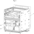
- Figure 2 shows a device (1) according to the invention from the rear, here also designed as a substructure unit with front cover and skirting board, e.g. suitable for a kitchen unit.
- the means (9) for generating compressed air, indicated here as a compressor, and the means (10) for generating negative pressure, indicated here as a vacuum pump are visible. These means are both provided in the container unit.
- the activated carbon filter (19) is mounted above the vacuum pump. The pressure/negative pressure lines are not shown.
- Figure 3 shows a device (1) according to the invention, as in Figure 1 shown, designed as a substructure unit with skirting board and control element, e.g. suitable for a kitchen unit.
- the front cover is not shown.
- the middle part which includes the container unit, is shown pulled out using the side pull-out rails.
- the upper part with the control elements, which includes the lid unit, is shown in the retracted state.
- the container unit includes two containers (2) with the respective side walls (3) and openings (6).
- the first seal (5) is provided at the opening of each container.
- FIG 4 shows a detailed view of the containers of the device according to the invention (1).
- the containers are essentially formed from the side walls (3) and the container floor (not visible here).
- the movable floor plate (4) is located inside the container.
- the first seal (5) is provided at the opening (6) of each container.
- the means for thermal welding (11) are designed as strip electrodes at the openings (6), but only around a third of the circumference of the openings (6).
- the corresponding electrodes on the lid not shown here (see Fig. 12 ), complete the means for thermal welding (11) to completely surround the openings. This ensures that the waste bag is completely sealed when welding.
- the strip electrodes can also be designed to completely surround the container opening.
- the control for the means for thermal welding (11a) supplies the means for thermal welding (11) at the opening (6) or the lid (7).
- the seal on the base plate (13) (also referred to as the "third seal") seals the base plate (4) against the side walls (3) in every position, in an embodiment described in detail above, airtight, preferably at least to prevent dirt from getting under the base plate (4).
- the opening (6) of the container is closed, it is thus sealed by the side walls (3) (these are also airtight) and either by the base plate (4), or at least by the container floor (18) (not shown here, see e.g. Fig.9 ), hermetically sealed.
- Compressed air can enter the interior of the container through the inlet opening (15) via the controlled inlet valve for compressed air (16).
- This compressed air is used to compress the waste in the waste bag arranged inside the container (and above the base plate) when the lid is in the closed position and presses the waste bag against the first seal (5).
- the compressed air is introduced into the interior of the container above the base plate.
- the fixing means (17) here designed as a clamping frame and shown in the closed state, encloses the opening (6) on the outside and, when a waste bag (not shown here) is inserted (with the clamping frame open), can clamp it and thus fix it to the container.
- the fixing means (17) only partially covers the first seal (5), here at the end of the opening (6) shown at the front in the figure.
- the means for fixing (17), serves to form a recess for perforation (25).
- a waste bag inserted with the clamping frame (17) open is stretched over the first seal (5) by means of the clamping frame.
- the recess for perforation (25), which is preferably formed by the clamping frame covering the first seal (5), the cover (a part of the waste bag or a separate part) and the waste bag would lie directly on top of each other when the waste bag is covered for welding, so that the means for perforation (21) could not perforate the cover or could only selectively perforate the cover under certain circumstances.
- the recess for perforation (25) thus protects the waste bag from the means for perforation (21), the latter can thus only perforate the cover in order to allow the gaseous atmosphere to be sucked out and/or the gaseous atmosphere to escape from the interior of the waste bag. This will be explained in more detail in Figure 17 described.
- FIG 5 shows a detailed view of the containers (2) of the device (1) according to the invention according to Figure 4 , only the means for fixing (17), designed here as a clamping frame, is shown in the open state. In this state, a waste bag (not shown here) can be inserted into the interior of the container through the opening (6).
- Figure 6 shows a detailed view of the containers (2) of the device (1) according to the invention from the rear.
- the containers (2) comprise the side walls (3) and the container floor (not visible here) and have the openings (6).
- the means (9) for generating compressed air, indicated here as a compressor, and the means (10) for generating negative pressure, indicated here as a vacuum pump, are arranged in the container unit of the device behind the containers.
- the activated carbon filter (19) is mounted above the vacuum pump.
- the control for the means for thermal welding (11a) is arranged below the compressor.
- Figure 7 shows a detailed view of the interior of a container (2) of the device (1) according to the invention.
- the area of the container (2) in which the waste bag can extend is delimited by the side walls (3) and the movable base plate (4), shown here in the "raised” state.
- the first seal (5) is provided at the opening (6) of the container, as well as the means for thermal welding (11).
- the seal on the base plate (13) seals the base plate (4) against the side walls (3), either airtight, preferably at least to prevent dirt from getting under the base plate (4).
- the means for fixing (17) only partially covers the first seal (5), here at the end of the opening shown at the front in the figure. In this area, according to a preferred embodiment of the present invention, the means for fixing (17) also serves to form the recess for the perforation (25).
- Figure 8 shows a detailed view of the interior of a container (2) of the device (1) according to the invention.
- the containers are essentially formed from the side walls (3) (front side wall is not shown) and the container floor (18).
- the area of the container (2) in which the waste bag can extend is limited by the side walls (3) and the movable base plate (4), shown here in the "lowered” state.
- the seal on the base plate (13) seals the base plate (4) from the side walls (3), either airtight, preferably at least to prevent dirt from getting under the base plate (4).
- the means for moving the base plate (14) preferably comprises both thrust elements, here designed as air bellows, which can move the base plate (4) towards the lid, and return elements, here designed as spiral springs.
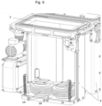
- Figure 9 shows a detailed view of the interior of a container (2) of the device (1) according to the invention according to Figure 8 .
- the containers are essentially made up of the side walls (3) (front side wall is not shown) and the container floor (18).
- the floor plate (4) is compared to Fig.8 not shown.
- the means for moving the base plate (14), shown here in the "lowered" state preferably comprise according to the invention both thrust elements, here designed as air bellows, which are connected by means of a holder and can move the base plate (4) towards the cover, as well as also return elements, here designed as spiral springs.
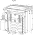
- Figure 10 shows a detailed view of the interior of a container (2) of the device (1) according to the invention according to Figure 8 , however, the movable base plate (4) is brought into the "raised” state by the means for moving the base plate (14).
- the means for moving the base plate (14) preferably comprises both thrust elements, here designed as air bellows, which can move the base plate (4) towards the lid, and return elements, here designed as spiral springs. The latter are tensioned in the "raised” state and enable the base plate to be returned, for example after the container has been emptied, ie after the pressed and welded waste bag has been removed.
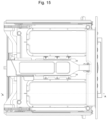
- Figure 11 shows a detailed view of the interior of a container (2) of the device (1) according to the invention according to Figure 10
- the means for moving the base plate (14) is shown in the "raised” state, the base plate is not shown.
- FIG 12 shows a detailed view of the lid (7) of the device (1) according to the invention, here in the extended state by means of pull-out rails (for service purposes).
- the lids (7) comprise the second seal (8) on the lid, which interacts with the first seal (5) on the container opening (not shown here) in the closed position.
- the means for thermal welding (11) are designed as strip electrodes, but only around two thirds of the circumference of the opening.
- the corresponding electrodes on the container opening, not shown here see e.g. Fig.4 ), the means for thermal welding (11) complete the complete circuit around the opening. This ensures that the waste bag is completely sealed during welding.
- the atmosphere can be extracted from the waste bag through the suction openings (12).
- FIG 13 shows a detailed view of the lids (7) of the device (1) according to the invention, here shown from below in the direction of the containers.
- the lids (7) comprise the second seal (8) on the lid, which interacts with the first seal (5) on the container opening (not shown here) in the closed position.
- the means for thermal welding (11) are designed as strip electrodes, but only around two thirds of the circumference of the opening. The atmosphere can be sucked out of the waste bag through the suction opening (12).
- the suction opening (12) also houses the means for perforation (21).
- the protective device (20) can be folded away during operation, thereby allowing the means for irradiation, typically a UV lamp, to optically access the interior of the container.
- the light from the UV lamp can thus, as soon as the protective device (20) has been moved aside, e.g. rotated or pushed, the interior of the Container.
- the protective device (20) In the closed state, the protective device (20) essentially forms a plane with the side surface of the lid (7), which in the closed position is directed towards the container.
- the covers (7) of the device (1) according to the invention remain in the retracted state during normal operation of the device, as in Figures 1 and 3
- the container unit is typically used, as shown in Fig.3 shown, extended, and after the waste has been deposited, retracted as shown in Fig.1 shown, retracted.
- the lid (7) with the second seal (8) is normally lowered so that the second seal (8) interacts with the first seal (5) on the container opening in the closed position and seals the waste bag by means of the lid (7). This prevents odor nuisance from the waste.
- the waste can be irradiated on the lid by the means for irradiating the interior of the container with UV light.
- the container unit is retracted after the waste has been introduced, it is irradiated and/or part of the atmosphere is sucked out of the waste bag.
- FIG 14 shows a detailed view of the lid (7) of the device (1) according to the invention, shown here from above.
- the atmosphere can be sucked out of the waste bag through the suction opening (12).
- the housing which normally encloses the suction opening, the UV lamp (26) and the protective device (20), is not shown.
- the waste bag can be perforated through the suction opening (12) by the perforation means (21), here indicated as a blade that moves across a semicircular cutting area.
- the perforation means (21) here indicated as a blade that moves across a semicircular cutting area.
- the UV lamp (26) and the protective device (20) are not visible; only the opening, which is normally filled by the protective device (20), is shown.
- Figure 15 shows the device (1) according to the invention schematically from above, in order to show the position of the section AA as in Figure 16 shown to illustrate.
- Figure 16 shows the section AA from Figure 15 .
- the lid unit with lid (7), the UV lamp (26) and the protective device (20) as well as the container opening are shown.
- the perforation means (21), indicated here as a blade protrudes through the suction opening (12) and perforates the part of the waste bag, or rather the separate part that covers the waste bag. This is explained in more detail in Figures 17 and 19 which represent section B.
- the side walls (3), the clamping frame (17) and the opening of the container are shown from the container (2).
- the waste bag is also indicated, as well as the part of the waste bag, or rather the separate part, which contains the waste bag, and thus spans the container opening. This is explained in more detail in Figures 17 to 20 explained.
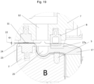
- Figure 17 shows section B from Figure 16 with more details for the perforating and suctioning process step.
- Section B shows the upper edge of the container (2) with the first seal (5) at the opening of the container.
- the lid (7) is shown in the closed position, the second seal (8) on the lid interacts with the first seal (5), here via part of the clamping frame (17) including a corresponding further seal on the clamping frame (17a).
- the means for thermal welding (11) are arranged on the lid, here designed as strip electrodes.
- a waste bag (23) is shown inserted into the container, which lies against the side wall (3) inside the container.
- the means for fixing the waste bag (17) here designed as a clamping frame, stretches the waste bag over the container opening, in particular over the first seal (5) at the opening of the container.
- the clamping frame (17) presses the waste bag (23) directly onto the first seal (5), since here the clamping frame (17), including the further seal on the clamping frame (17a), protrudes beyond the first seal (5).
- the means for fixing the waste bag (17) merely stretches the waste bag over the first seal (5).
- a part for example a tab of the waste bag, or, preferably, a separate part of the waste bag (24), for example from an endless roll, must be placed over the container opening.
- the tensioning frame only stretches the waste bag over the first seal (5).
- the second seal (8) of the lid is pressed directly onto the first seal (5).
- the second seal (8) of the lid seals the part of the waste bag, for example a flap of the waste bag, or, preferably, the separate part (24) against the waste bag (23).
- the interior of the waste bag is hermetically sealed from the environment.
- this also means that the atmosphere from the interior of the waste bag could not be sucked out in this state, or that the atmosphere from the interior of the waste bag could not escape when the waste bag is compressed.
- a defined opening is created in the cover of the waste bag by the perforation means (21).
- the recess for perforation (25) created by the tensioning frame (17) by covering the first seal (5) enables selective perforation of the covering part of the waste bag, for example a tab of the waste bag, or, preferably, the separate part (24), as in Figure 17
- the means for fixing (17) serves to form a recess for perforation (25).
- the recess for perforation (25) which is preferably formed by the clamping frame covering the first seal (5), when the waste bag is covered for welding, the cover (a part of the waste bag or a separate part) and the waste bag would lie directly on top of each other, so that only the cover could not be selectively perforated by the means for perforation (21).
- the recess for perforation (25) thus protects the waste bag from the means for perforation (21), the latter can therefore only perforate the cover.
- part of the atmosphere can be sucked out of the interior of the waste bag through the suction opening (12), as indicated by the arrow, or part of the atmosphere can escape from the interior of the waste bag when it is compressed, namely through the suction gap (22) which remains between the waste bag (23) and the covering part of the waste bag, for example a tab of the waste bag, or, preferably, the separate part (24).
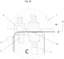
- Figure 18 shows section C from Figure 16 with more details according to the process step of perforating and suction as in Figure 17 .
- Detail C shows the upper edge of the container (2) with the first seal (5) at the opening of the container.
- the lid (7) is shown in the closed position, the second seal (8) on the lid interacts with the first seal (5).
- the means for thermal welding (11) are arranged on the container, here designed as strip electrodes.
- a waste bag (23) is placed in the container, which lies against the side wall (3) inside the container.
- the means for fixing the waste bag (17) here designed as a tensioning frame, stretches the waste bag over the container opening, in particular over the first seal (5) at the opening of the container.
- a part for example a tab of the waste bag, or, preferably, a separate part of the waste bag (24), for example from an endless roll, is wound over the Container opening.
- the lid is brought into the closed position.
- the second seal (8) of the lid is pressed onto the first seal (5), and the second seal (8) of the lid seals the part of the waste bag, for example a tab of the waste bag, or, preferably, the separate part (24) against the waste bag (23).
- the interior of the waste bag is hermetically sealed from the environment.
- the suction gap (22) remains between the waste bag (23) and the covering part of the waste bag, for example a tab of the waste bag, or, preferably, the separate part (24).
- FIG 19 shows section B from Figure 16 with more details for the welding process step.
- the lid is also shown in the closed position, but lowered further to allow the waste bag to be welded.
- the lid is moved further towards the upper edge of the container (2) with the first seal (5), the second seal (8) on the lid continues to interact with the first seal (5), here via part of the clamping frame (17) including a corresponding further seal (17a).
- the remaining suction gap (22) is closed.
- the waste bag (23) placed in the container is thus in contact with the part, for example a tab of the waste bag, or preferably a separate part of the waste bag (24), for example from an endless roll, below the means for thermal welding (11) and can be welded to it and thus sealed.
- the part for example a tab of the waste bag, or preferably a separate part of the waste bag (24), for example from an endless roll, below the means for thermal welding (11) and can be welded to it and thus sealed.
- Figure 20 shows section C from Figure 16 with more details for the welding process step.
- the lid is also in the closed position, but lowered further to allow welding of the waste bag.
- the lid is moved further towards the upper edge of the container (2) with the first seal (5), the second seal (8) on the lid continues to interact with the first seal (5), here via a part of the clamping frame (17) including a corresponding further seal (17a).
- the means for thermal welding (11) arranged on the container (2), here designed as strip electrodes, are now in direct contact with the corresponding counter surface of the lid, which in Figure 18
- the remaining suction gap (22) is closed.
- the waste bag (23) placed in the container is thus above the means for thermal welding (11) with the part, for example a flap of the waste bag, or, preferably, a separate part of the waste bag (24), for example from an endless roll, and can be welded to it and thus sealed.
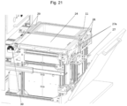
- the separate part of the waste bag (24) comes, as shown in the figure, from a roll (30) (endless roll) which stores several parts of the waste bag (24) intended to cover the waste bag.
- the roll (30) is preferably arranged at the rear end of the container, ie at the end of the container further away from the front cover.
- the roll (30) is therefore preferably arranged in such a way that, in order to close the waste bag, according to the invention a separate part of the waste bag (24) can be unrolled from the roll (30) and placed over the container opening.
- the part of the waste bag (24) can then be fixed by the means for fixing the cover of the waste bag (27), here designed as a foldable frame on the front of the container.
- the means for fixing the cover of the waste bag (27) presses the part of the waste bag (24) preferably onto mandrels for fixing the cover of the waste bag (27a).
- Means for separating (29), here designed as a cutting electrode, are typically present between the roll (30) and the opening of the container.
- the means for separating (29) can also be designed as a tear-off edge.
- Safety switches (28) are preferably arranged in such a way that they are activated when the part of the waste bag (24) is correctly placed on the opening of the container.
- the part (24) can be fixed by the means for fixing the cover of the waste bag (27), the safety switches (28) being activated when the part (24) is correctly placed on the opening of the container.
- the waste bag can then be welded all the way around to the opening of the container by the means for thermal welding (11) and thus closed and, preferably after the waste bag has been welded, the part (24) can be separated from the roll (30) by the means for separating (29). Finally, the welded waste bag can be removed after the means for fixing the cover (27) and the means for fixing the waste bag (17) have been opened. be removed from the container.
- Figure 22 shows the section of a preferred device according to the invention according to Figure 21 .
- the opening of the container is covered and closed by a separate part of the waste bag (24).
- the means for fixing the cover of the waste bag (27) here designed as a folding frame on the front of the container, is shown closed.
- the part of the waste bag (24) is thus fixed.
- the means for fixing the cover of the waste bag (27) presses the part of the waste bag (24) preferably onto mandrels for fixing the cover of the waste bag (27a) and activates the safety switches (28) (not shown here).
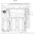
- Figure 23 shows a section through a preferred device according to the invention according to Figure 16 .
- the opening of the container is covered by a separate part of the waste bag (24) and the inserted waste bag (23) is shown closed with it.
- the separate part of the waste bag (24), as shown in the figure, comes from a roll (30) (endless roll) which stores several parts of the waste bag (24) intended to cover the waste bag.
- three means are used simultaneously to reduce the volume of waste: firstly, suction of the gaseous atmosphere from the waste bag; secondly, mechanical compression, which serves to support the removal of the gaseous atmosphere and, above all, enables higher pressures to be applied to the waste; and finally, thirdly, the action of compressed air on the outside of the waste bag.
- the suction of the gaseous atmosphere from the waste bag, which creates a negative pressure in the waste bag, is shown in the figure as "A”.
- the pressurization is illustrated by the arrows marked "B”.
- the latter is brought about by introducing compressed air into the container, here below the base plate.
- the compressed air flows past the seals of the base plate and acts on the waste bag, which is sealed against the lid.
- the force from lifting the base plate causes the waste to be mechanically compressed.
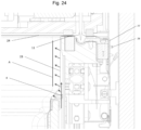
- Figure 24 shows a section corresponding Figure 17 with more details for the process step of perforating and suctioning as well as air pressure. Shown is the upper edge of the container, the lid is in the closed position, the second seal on the lid interacts with the first seal, here over a part of the clamping frame including a corresponding further seal on the clamping frame (as in Figure 17 ).
- the means for thermal welding (11) are arranged at the container opening, here designed as strip electrodes.
- a waste bag is placed in the container (23) is shown inserted, this rests against the side wall (and the base plate, not shown here) inside the container. The waste bag is stretched over the container opening by the means for fixing the waste bag, here designed as a tensioning frame.
- a part for example a tab of the waste bag, or, preferably, a separate part of the waste bag (24), for example from an endless roll, is placed over the container opening.
- This is typically done manually when the container unit is pulled out, but corresponding means can also be provided which automatically position the separate part (24), for example from an endless roll, over the container opening.
- the separate part of the waste bag (24) is clamped by the means for fixing the cover of the waste bag (27), a correctly inserted part (24) activates the safety switches (28). With the lid in the closed position, the second seal of the lid is positioned directly on the first seal of the container (see more precisely in Figure 17 ).
- the seals of the lid and the container seal the separate part (24) against the waste bag (23). In this position, the interior of the waste bag is hermetically sealed against the environment. In order to enable the atmosphere to be sucked out of the interior of the bag, a defined opening is created in the cover of the waste bag by the perforation means. After the perforation has been made, part of the atmosphere can be sucked out of the interior of the waste bag through the suction opening on the lid, or part of the atmosphere can escape from the interior of the waste bag when it is compressed.
- the suction of the gaseous atmosphere from the waste bag which creates a negative pressure in the waste bag, is shown in the figure as "A”.
- the pressurization is illustrated by the arrows marked "B”. The latter is brought about by introducing compressed air into the container, here below the base plate. The compressed air flows past the seals of the base plate and acts on the waste bag, which is sealed against the lid. The force caused by lifting the base plate causes the waste to be mechanically compressed.
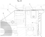
- Figure 25 shows the Figure 24 corresponding cutout at the other end of the container, according to Figure 18 . Shown is the top edge of the container, the lid is in the closed position, the second seal on the lid interacts with the first seal (as in Figure 18 ).
- the means for thermal welding (11) are arranged at the container opening, here designed as strip electrodes.
- a waste bag (23) is shown inserted into the container. The waste bag is stretched over the container opening by the means for fixing the waste bag, here designed as a tensioning frame.
- a separate part of the waste bag (24) is pulled from a roll (30) over the container opening and the inserted waste bag, typically manually with the container unit pulled out, but corresponding means can also be provided which automatically position the separate part (24) over the container opening.
- the seals of the lid and the container seal the separate part (24) against the waste bag (23).
- the suction of the gaseous atmosphere from the waste bag, which creates a negative pressure in the waste bag, is shown in the figure as "A”.
- the pressurization is illustrated by the arrows marked “B”.
- the waste bag is closed by welding to the separate part (24), and the latter is separated from the roll (30) by the means for separating the separate part (29), here designed as a cutting electrode.
- This provides a waste container in which a comparatively large amount of waste can be collected and stored, which can be compacted to the maximum and then disposed of cleanly, and which is also easy to use.
Landscapes
- Engineering & Computer Science (AREA)
- Mechanical Engineering (AREA)
- Physics & Mathematics (AREA)
- Fluid Mechanics (AREA)
- Refuse Receptacles (AREA)
- Processing Of Solid Wastes (AREA)
- Electrical Discharge Machining, Electrochemical Machining, And Combined Machining (AREA)
- Press Drives And Press Lines (AREA)
Priority Applications (16)
| Application Number | Priority Date | Filing Date | Title |
|---|---|---|---|
| HRP20240721TT HRP20240721T1 (hr) | 2021-11-04 | 2021-11-04 | Uređaj za sakupljanje i sabijanje otpadaka |
| RS20240599A RS65560B1 (sr) | 2021-11-04 | 2021-11-04 | Uređaj za sakupljanje i sabijanje otpadaka |
| MA63186A MA63186B1 (fr) | 2021-11-04 | 2021-11-04 | Dispositif de collecte et de compression de déchets |
| HUE21206532A HUE066995T2 (hu) | 2021-11-04 | 2021-11-04 | Hulladékgyûjtõ és -tömörítõ berendezés |
| ES21206532T ES2980896T3 (es) | 2021-11-04 | 2021-11-04 | Dispositivo de recolección y compactación de residuos |
| PL21206532.0T PL4177184T3 (pl) | 2021-11-04 | 2021-11-04 | Urządzenie do zbierania i zagęszczania odpadów |
| EP21206532.0A EP4177184B1 (de) | 2021-11-04 | 2021-11-04 | Vorrichtung zur sammlung und verdichtung von abfällen |
| US18/707,352 US20260001713A1 (en) | 2021-11-04 | 2022-10-14 | Device for collecting and compacting waste |
| PCT/EP2022/078628 WO2023078655A1 (de) | 2021-11-04 | 2022-10-14 | Vorrichtung zur sammlung und verdichtung von abfällen |
| CN202280085981.7A CN119013201A (zh) | 2021-11-04 | 2022-10-14 | 用于收集和压缩废物的装置 |
| MX2024005468A MX2024005468A (es) | 2021-11-04 | 2022-10-14 | Dispositivo de recogida y compactacion de residuos. |
| KR1020247017272A KR20240102983A (ko) | 2021-11-04 | 2022-10-14 | 폐기물을 수집 및 압축하기 위한 디바이스 |
| AU2022381360A AU2022381360B2 (en) | 2021-11-04 | 2022-10-14 | Device for collecting and compacting waste |
| CA3237250A CA3237250A1 (en) | 2021-11-04 | 2022-10-14 | Device for collecting and compacting waste |
| JP2024527082A JP2024544503A (ja) | 2021-11-04 | 2022-10-14 | 廃棄物を収集および圧縮処理するための装置 |
| ZA2024/03338A ZA202403338B (en) | 2021-11-04 | 2024-04-29 | Device for collecting and compacting waste |
Applications Claiming Priority (1)
| Application Number | Priority Date | Filing Date | Title |
|---|---|---|---|
| EP21206532.0A EP4177184B1 (de) | 2021-11-04 | 2021-11-04 | Vorrichtung zur sammlung und verdichtung von abfällen |
Publications (3)
| Publication Number | Publication Date |
|---|---|
| EP4177184A1 EP4177184A1 (de) | 2023-05-10 |
| EP4177184B1 true EP4177184B1 (de) | 2024-05-01 |
| EP4177184C0 EP4177184C0 (de) | 2024-05-01 |
Family
ID=78528755
Family Applications (1)
| Application Number | Title | Priority Date | Filing Date |
|---|---|---|---|
| EP21206532.0A Active EP4177184B1 (de) | 2021-11-04 | 2021-11-04 | Vorrichtung zur sammlung und verdichtung von abfällen |
Country Status (16)
| Country | Link |
|---|---|
| US (1) | US20260001713A1 (enExample) |
| EP (1) | EP4177184B1 (enExample) |
| JP (1) | JP2024544503A (enExample) |
| KR (1) | KR20240102983A (enExample) |
| CN (1) | CN119013201A (enExample) |
| AU (1) | AU2022381360B2 (enExample) |
| CA (1) | CA3237250A1 (enExample) |
| ES (1) | ES2980896T3 (enExample) |
| HR (1) | HRP20240721T1 (enExample) |
| HU (1) | HUE066995T2 (enExample) |
| MA (1) | MA63186B1 (enExample) |
| MX (1) | MX2024005468A (enExample) |
| PL (1) | PL4177184T3 (enExample) |
| RS (1) | RS65560B1 (enExample) |
| WO (1) | WO2023078655A1 (enExample) |
| ZA (1) | ZA202403338B (enExample) |
Families Citing this family (2)
| Publication number | Priority date | Publication date | Assignee | Title |
|---|---|---|---|---|
| MA71597B1 (fr) * | 2023-04-26 | 2026-01-30 | Dlr Gbr | Dispositif mobile pour la collecte et la compression de déchets |
| DE102024207189A1 (de) * | 2024-07-30 | 2026-02-05 | BORA - Vertriebs GmbH & Co KG | Kompaktiervorrichtung zum Kompaktieren von gesammelten Objekten, insbesondere Haushaltspresse für Abfälle, Abfallsystem für eine Haushaltsküche und Verfahren zum Kompaktieren von gesammelten Objekten |
Family Cites Families (12)
| Publication number | Priority date | Publication date | Assignee | Title |
|---|---|---|---|---|
| DE3231221A1 (de) * | 1982-08-21 | 1984-03-01 | Manfred Jacob | Verfahren und vorrichtung zum verpacken kontaminierter abfallstoffe |
| CH668239A5 (de) | 1985-04-29 | 1988-12-15 | Martin Lustenberger | Verfahren und vorrichtung zum verdichten von abfaellen. |
| JPH01120997U (enExample) * | 1988-02-05 | 1989-08-16 | ||
| DE3903280A1 (de) * | 1989-02-03 | 1990-08-09 | Multivac Haggenmueller Kg | Vakuumverpackungsmaschine zum verpacken von zu entsorgendem gut |
| JPH07215403A (ja) * | 1994-02-03 | 1995-08-15 | Yadaman R D Koubou:Kk | 廃棄物の圧縮梱包機 |
| GB2387527B (en) * | 2002-04-17 | 2005-08-10 | Mark Hamilton Jardine | Waste compaction unit and method |
| JP2004115185A (ja) * | 2002-09-25 | 2004-04-15 | Matsushita Electric Works Ltd | ごみ圧縮装置 |
| ITPD20030164A1 (it) | 2003-07-17 | 2005-01-18 | Rosolini Ltd | Apparecchiatura per la raccolta e lo smaltimento |
| US7285928B1 (en) * | 2005-10-19 | 2007-10-23 | Jolly David M | Container for use with flexible bags |
| WO2007076964A1 (de) | 2005-12-21 | 2007-07-12 | Christian Lanzl | Abfallbehälter |
| CN110947473A (zh) * | 2019-10-24 | 2020-04-03 | 东莞市邦泽电子有限公司 | 一种碎纸机压缩和封装的纸屑收集方法 |
| JP7001653B2 (ja) * | 2019-11-01 | 2022-01-19 | 日機装株式会社 | 殺菌脱臭装置およびゴミ箱 |
-
2021
- 2021-11-04 ES ES21206532T patent/ES2980896T3/es active Active
- 2021-11-04 PL PL21206532.0T patent/PL4177184T3/pl unknown
- 2021-11-04 HR HRP20240721TT patent/HRP20240721T1/hr unknown
- 2021-11-04 RS RS20240599A patent/RS65560B1/sr unknown
- 2021-11-04 HU HUE21206532A patent/HUE066995T2/hu unknown
- 2021-11-04 MA MA63186A patent/MA63186B1/fr unknown
- 2021-11-04 EP EP21206532.0A patent/EP4177184B1/de active Active
-
2022
- 2022-10-14 KR KR1020247017272A patent/KR20240102983A/ko active Pending
- 2022-10-14 WO PCT/EP2022/078628 patent/WO2023078655A1/de not_active Ceased
- 2022-10-14 AU AU2022381360A patent/AU2022381360B2/en active Active
- 2022-10-14 MX MX2024005468A patent/MX2024005468A/es unknown
- 2022-10-14 US US18/707,352 patent/US20260001713A1/en active Pending
- 2022-10-14 CN CN202280085981.7A patent/CN119013201A/zh active Pending
- 2022-10-14 CA CA3237250A patent/CA3237250A1/en active Pending
- 2022-10-14 JP JP2024527082A patent/JP2024544503A/ja active Pending
-
2024
- 2024-04-29 ZA ZA2024/03338A patent/ZA202403338B/en unknown
Also Published As
| Publication number | Publication date |
|---|---|
| MX2024005468A (es) | 2024-07-22 |
| ES2980896T3 (es) | 2024-10-03 |
| JP2024544503A (ja) | 2024-12-03 |
| US20260001713A1 (en) | 2026-01-01 |
| RS65560B1 (sr) | 2024-06-28 |
| MA63186B1 (fr) | 2024-09-30 |
| CN119013201A (zh) | 2024-11-22 |
| HUE066995T2 (hu) | 2024-10-28 |
| EP4177184A1 (de) | 2023-05-10 |
| ZA202403338B (en) | 2025-01-29 |
| EP4177184C0 (de) | 2024-05-01 |
| WO2023078655A1 (de) | 2023-05-11 |
| KR20240102983A (ko) | 2024-07-03 |
| AU2022381360B2 (en) | 2025-10-16 |
| PL4177184T3 (pl) | 2024-07-15 |
| CA3237250A1 (en) | 2023-05-11 |
| HRP20240721T1 (hr) | 2024-12-06 |
| AU2022381360A1 (en) | 2024-05-16 |
Similar Documents
| Publication | Publication Date | Title |
|---|---|---|
| EP0381020B1 (de) | Vakuumverpackungsmaschine zum Verpacken von zu entsorgendem Gut | |
| DE69615072T2 (de) | Vorrichtung zum Verdichten von festen, anorganischen, städtischen Abfällen | |
| WO2023078655A1 (de) | Vorrichtung zur sammlung und verdichtung von abfällen | |
| EP3166874B1 (de) | Vorrichtung sowie umhüllungsverfahren zum portionsweisen verschliessen von exkrementen, verbandsmaterialien, damenhygieneartikeln oder dergleichen in umhüllungen | |
| DE19737338A1 (de) | Verfahren zum Verpacken von Gefriergut, Abfall, Speiseresten und dergleichen | |
| DE102019115190A1 (de) | Entsorgungsstation | |
| EP4455051B1 (de) | Mobile vorrichtung zur sammlung und verdichtung von abfällen | |
| WO2010145042A1 (de) | Vorrichtung zum ausschleusen von transfergut aus einem containment und verfahren dazu | |
| RU2842964C2 (ru) | Устройство для сбора и уплотнения отходов | |
| WO2007076964A1 (de) | Abfallbehälter | |
| HK40092413B (en) | Device for collecting and compacting waste | |
| DE102018101149A9 (de) | Vakuumierer mit Schneidvorrichtung | |
| CA3287141A1 (en) | Mobile device for collecting and compacting waste | |
| EP3401237A1 (de) | Behältnis | |
| JP2934806B2 (ja) | コンパクター及び廃棄物の圧縮方法 | |
| DE20207422U1 (de) | Abfallsammelvorrichtung | |
| DE102024207189A1 (de) | Kompaktiervorrichtung zum Kompaktieren von gesammelten Objekten, insbesondere Haushaltspresse für Abfälle, Abfallsystem für eine Haushaltsküche und Verfahren zum Kompaktieren von gesammelten Objekten | |
| DE19705136C2 (de) | Gerät zur Verkleinerung des Volumens von geleerten Metalldosen | |
| EP0621804B1 (de) | Vorrichtung zum auffangen von shreddergut | |
| WO2022038197A1 (de) | Abfallbehandlungsvorrichtung sowie verfahren zur abfallbehandlung für den maritimen anwendungsbereich | |
| DE202010009689U1 (de) | Gerät zum Verschließen von beispielsweise mit Lebensmitteln gefüllten Beuteln aus Kunststoff-Folie | |
| EP0874770A1 (de) | Verfahren zum verpacken von gefriergut, zu entsorgendem gut wie beispielsweise hausmüll u. dgl. | |
| DE202004009948U1 (de) | Einbaufähiges Entsorgungssystem für Abfallstoffe mit einer Vorrichtung zum Verdichten von Abfallstoffen verschiedenster Art | |
| DE9218236U1 (de) | Vorrichtung zum Auffangen von Shreddergut | |
| DE10043672A1 (de) | Gerät zur sicheren Unterbringung von Biomüll |
Legal Events
| Date | Code | Title | Description |
|---|---|---|---|
| REG | Reference to a national code |
Ref country code: HR Ref legal event code: TUEP Ref document number: P20240721T Country of ref document: HR |
|
| PUAI | Public reference made under article 153(3) epc to a published international application that has entered the european phase |
Free format text: ORIGINAL CODE: 0009012 |
|
| STAA | Information on the status of an ep patent application or granted ep patent |
Free format text: STATUS: THE APPLICATION HAS BEEN PUBLISHED |
|
| AK | Designated contracting states |
Kind code of ref document: A1 Designated state(s): AL AT BE BG CH CY CZ DE DK EE ES FI FR GB GR HR HU IE IS IT LI LT LU LV MC MK MT NL NO PL PT RO RS SE SI SK SM TR |
|
| STAA | Information on the status of an ep patent application or granted ep patent |
Free format text: STATUS: REQUEST FOR EXAMINATION WAS MADE |
|
| 17P | Request for examination filed |
Effective date: 20230605 |
|
| RBV | Designated contracting states (corrected) |
Designated state(s): AL AT BE BG CH CY CZ DE DK EE ES FI FR GB GR HR HU IE IS IT LI LT LU LV MC MK MT NL NO PL PT RO RS SE SI SK SM TR |
|
| RAV | Requested validation state of the european patent: fee paid |
Extension state: TN Effective date: 20231108 Extension state: MA Effective date: 20231108 |
|
| RAX | Requested extension states of the european patent have changed |
Extension state: ME Payment date: 20231108 Extension state: BA Payment date: 20231108 |
|
| REG | Reference to a national code |
Ref country code: HK Ref legal event code: DE Ref document number: 40092413 Country of ref document: HK |
|
| RAP3 | Party data changed (applicant data changed or rights of an application transferred) |
Owner name: DLR GBR |
|
| GRAP | Despatch of communication of intention to grant a patent |
Free format text: ORIGINAL CODE: EPIDOSNIGR1 |
|
| RIC1 | Information provided on ipc code assigned before grant |
Ipc: B65F 1/16 20060101ALI20231218BHEP Ipc: B65F 1/06 20060101ALI20231218BHEP Ipc: B30B 9/30 20060101ALI20231218BHEP Ipc: B30B 1/00 20060101ALI20231218BHEP Ipc: B65F 1/14 20060101AFI20231218BHEP |
|
| STAA | Information on the status of an ep patent application or granted ep patent |
Free format text: STATUS: GRANT OF PATENT IS INTENDED |
|
| INTG | Intention to grant announced |
Effective date: 20240125 |
|
| GRAS | Grant fee paid |
Free format text: ORIGINAL CODE: EPIDOSNIGR3 |
|
| GRAA | (expected) grant |
Free format text: ORIGINAL CODE: 0009210 |
|
| STAA | Information on the status of an ep patent application or granted ep patent |
Free format text: STATUS: THE PATENT HAS BEEN GRANTED |
|
| AK | Designated contracting states |
Kind code of ref document: B1 Designated state(s): AL AT BE BG CH CY CZ DE DK EE ES FI FR GB GR HR HU IE IS IT LI LT LU LV MC MK MT NL NO PL PT RO RS SE SI SK SM TR |
|
| REG | Reference to a national code |
Ref country code: GB Ref legal event code: FG4D Free format text: NOT ENGLISH Ref country code: TN Ref legal event code: VAGR Ref document number: TN/P/2024/000170 Country of ref document: TN |
|
| REG | Reference to a national code |
Ref country code: CH Ref legal event code: EP |
|
| REG | Reference to a national code |
Ref country code: IE Ref legal event code: FG4D Free format text: LANGUAGE OF EP DOCUMENT: GERMAN |
|
| REG | Reference to a national code |
Ref country code: DE Ref legal event code: R096 Ref document number: 502021003551 Country of ref document: DE |
|
| REG | Reference to a national code |
Ref country code: RO Ref legal event code: EPE |
|
| U01 | Request for unitary effect filed |
Effective date: 20240501 |
|
| U07 | Unitary effect registered |
Designated state(s): AT BE BG DE DK EE FI FR IT LT LU LV MT NL PT SE SI Effective date: 20240513 |
|
| REG | Reference to a national code |
Ref country code: GR Ref legal event code: EP Ref document number: 20240401204 Country of ref document: GR Effective date: 20240716 |
|
| REG | Reference to a national code |
Ref country code: MA Ref legal event code: VAGR Ref document number: 63186 Country of ref document: MA Kind code of ref document: B1 |
|
| REG | Reference to a national code |
Ref country code: ES Ref legal event code: FG2A Ref document number: 2980896 Country of ref document: ES Kind code of ref document: T3 Effective date: 20241003 |
|
| REG | Reference to a national code |
Ref country code: HU Ref legal event code: AG4A Ref document number: E066995 Country of ref document: HU |
|
| REG | Reference to a national code |
Ref country code: HR Ref legal event code: ODRP Ref document number: P20240721T Country of ref document: HR Payment date: 20241030 Year of fee payment: 4 |
|
| REG | Reference to a national code |
Ref country code: HR Ref legal event code: T1PR Ref document number: P20240721 Country of ref document: HR |
|
| U20 | Renewal fee for the european patent with unitary effect paid |
Year of fee payment: 4 Effective date: 20241120 |
|
| PG25 | Lapsed in a contracting state [announced via postgrant information from national office to epo] |
Ref country code: SK Free format text: LAPSE BECAUSE OF FAILURE TO SUBMIT A TRANSLATION OF THE DESCRIPTION OR TO PAY THE FEE WITHIN THE PRESCRIBED TIME-LIMIT Effective date: 20240501 |
|
| PG25 | Lapsed in a contracting state [announced via postgrant information from national office to epo] |
Ref country code: SM Free format text: LAPSE BECAUSE OF FAILURE TO SUBMIT A TRANSLATION OF THE DESCRIPTION OR TO PAY THE FEE WITHIN THE PRESCRIBED TIME-LIMIT Effective date: 20240501 |
|
| PG25 | Lapsed in a contracting state [announced via postgrant information from national office to epo] |
Ref country code: SM Free format text: LAPSE BECAUSE OF FAILURE TO SUBMIT A TRANSLATION OF THE DESCRIPTION OR TO PAY THE FEE WITHIN THE PRESCRIBED TIME-LIMIT Effective date: 20240501 Ref country code: SK Free format text: LAPSE BECAUSE OF FAILURE TO SUBMIT A TRANSLATION OF THE DESCRIPTION OR TO PAY THE FEE WITHIN THE PRESCRIBED TIME-LIMIT Effective date: 20240501 |
|
| REG | Reference to a national code |
Ref country code: DE Ref legal event code: R097 Ref document number: 502021003551 Country of ref document: DE |
|
| PLBE | No opposition filed within time limit |
Free format text: ORIGINAL CODE: 0009261 |
|
| STAA | Information on the status of an ep patent application or granted ep patent |
Free format text: STATUS: NO OPPOSITION FILED WITHIN TIME LIMIT |
|
| 26N | No opposition filed |
Effective date: 20250204 |
|
| REG | Reference to a national code |
Ref country code: HR Ref legal event code: ODRP Ref document number: P20240721 Country of ref document: HR Payment date: 20251029 Year of fee payment: 5 |
|
| VSFP | Annual fee paid to validation state [announced via postgrant information from national office to epo] |
Ref country code: MA Payment date: 20251104 Year of fee payment: 5 Ref country code: MA Payment date: 20241017 Year of fee payment: 4 |
|
| REG | Reference to a national code |
Ref country code: CH Ref legal event code: U11 Free format text: ST27 STATUS EVENT CODE: U-0-0-U10-U11 (AS PROVIDED BY THE NATIONAL OFFICE) Effective date: 20251201 |
|
| PGFP | Annual fee paid to national office [announced via postgrant information from national office to epo] |
Ref country code: HU Payment date: 20251106 Year of fee payment: 5 |
|
| U20 | Renewal fee for the european patent with unitary effect paid |
Year of fee payment: 5 Effective date: 20251119 |
|
| PGFP | Annual fee paid to national office [announced via postgrant information from national office to epo] |
Ref country code: IS Payment date: 20251124 Year of fee payment: 5 |
|
| PGFP | Annual fee paid to national office [announced via postgrant information from national office to epo] |
Ref country code: GB Payment date: 20251120 Year of fee payment: 5 |
|
| PGFP | Annual fee paid to national office [announced via postgrant information from national office to epo] |
Ref country code: NO Payment date: 20251118 Year of fee payment: 5 Ref country code: MC Payment date: 20251118 Year of fee payment: 5 |
|
| PGFP | Annual fee paid to national office [announced via postgrant information from national office to epo] |
Ref country code: HR Payment date: 20251029 Year of fee payment: 5 |
|
| PGFP | Annual fee paid to national office [announced via postgrant information from national office to epo] |
Ref country code: TR Payment date: 20251030 Year of fee payment: 5 Ref country code: GR Payment date: 20251117 Year of fee payment: 5 |
|
| PGFP | Annual fee paid to national office [announced via postgrant information from national office to epo] |
Ref country code: CH Payment date: 20251201 Year of fee payment: 5 |
|
| PGFP | Annual fee paid to national office [announced via postgrant information from national office to epo] |
Ref country code: IE Payment date: 20251120 Year of fee payment: 5 Ref country code: CZ Payment date: 20251023 Year of fee payment: 5 |
|
| PGFP | Annual fee paid to national office [announced via postgrant information from national office to epo] |
Ref country code: PL Payment date: 20251027 Year of fee payment: 5 |
|
| PGFP | Annual fee paid to national office [announced via postgrant information from national office to epo] |
Ref country code: RO Payment date: 20251028 Year of fee payment: 5 |
|
| PGFP | Annual fee paid to national office [announced via postgrant information from national office to epo] |
Ref country code: RS Payment date: 20251023 Year of fee payment: 5 |
|
| PGFP | Annual fee paid to national office [announced via postgrant information from national office to epo] |
Ref country code: ES Payment date: 20251216 Year of fee payment: 5 |
|
| PG25 | Lapsed in a contracting state [announced via postgrant information from national office to epo] |
Ref country code: CY Free format text: LAPSE BECAUSE OF FAILURE TO SUBMIT A TRANSLATION OF THE DESCRIPTION OR TO PAY THE FEE WITHIN THE PRESCRIBED TIME-LIMIT; INVALID AB INITIO Effective date: 20211104 |