EP4159480B1 - Pneumatique - Google Patents
Pneumatique Download PDFInfo
- Publication number
- EP4159480B1 EP4159480B1 EP21812215.8A EP21812215A EP4159480B1 EP 4159480 B1 EP4159480 B1 EP 4159480B1 EP 21812215 A EP21812215 A EP 21812215A EP 4159480 B1 EP4159480 B1 EP 4159480B1
- Authority
- EP
- European Patent Office
- Prior art keywords
- tire
- reinforcement layer
- turn
- radial direction
- ply
- Prior art date
- Legal status (The legal status is an assumption and is not a legal conclusion. Google has not performed a legal analysis and makes no representation as to the accuracy of the status listed.)
- Active
Links
Images


Classifications
-
- B—PERFORMING OPERATIONS; TRANSPORTING
- B60—VEHICLES IN GENERAL
- B60C—VEHICLE TYRES; TYRE INFLATION; TYRE CHANGING; CONNECTING VALVES TO INFLATABLE ELASTIC BODIES IN GENERAL; DEVICES OR ARRANGEMENTS RELATED TO TYRES
- B60C15/00—Tyre beads, e.g. ply turn-up or overlap
- B60C15/06—Flipper strips, fillers, or chafing strips and reinforcing layers for the construction of the bead
- B60C15/0628—Flipper strips, fillers, or chafing strips and reinforcing layers for the construction of the bead comprising a bead reinforcing layer
- B60C15/0635—Flipper strips, fillers, or chafing strips and reinforcing layers for the construction of the bead comprising a bead reinforcing layer using chippers between the carcass layer and chafer rubber wrapped around the bead
-
- B—PERFORMING OPERATIONS; TRANSPORTING
- B60—VEHICLES IN GENERAL
- B60C—VEHICLE TYRES; TYRE INFLATION; TYRE CHANGING; CONNECTING VALVES TO INFLATABLE ELASTIC BODIES IN GENERAL; DEVICES OR ARRANGEMENTS RELATED TO TYRES
- B60C15/00—Tyre beads, e.g. ply turn-up or overlap
- B60C15/06—Flipper strips, fillers, or chafing strips and reinforcing layers for the construction of the bead
- B60C15/0628—Flipper strips, fillers, or chafing strips and reinforcing layers for the construction of the bead comprising a bead reinforcing layer
- B60C2015/0678—Physical properties of the bead reinforcing layer, e.g. modulus of the ply
-
- B—PERFORMING OPERATIONS; TRANSPORTING
- B60—VEHICLES IN GENERAL
- B60C—VEHICLE TYRES; TYRE INFLATION; TYRE CHANGING; CONNECTING VALVES TO INFLATABLE ELASTIC BODIES IN GENERAL; DEVICES OR ARRANGEMENTS RELATED TO TYRES
- B60C15/00—Tyre beads, e.g. ply turn-up or overlap
- B60C15/06—Flipper strips, fillers, or chafing strips and reinforcing layers for the construction of the bead
- B60C15/0628—Flipper strips, fillers, or chafing strips and reinforcing layers for the construction of the bead comprising a bead reinforcing layer
- B60C2015/0692—Flipper strips, fillers, or chafing strips and reinforcing layers for the construction of the bead comprising a bead reinforcing layer characterised by particular materials of the cords
Definitions
- the present invention relates to a pneumatic tire.
- Patent Literature (PTL) 1 and 2 disclose a pneumatic tire having a reinforcement layer, made of organic fibers, arranged outward in the tire width direction from the turn-up portion of the carcass ply.
- WO2011142389A1 discloses a pneumatic tire which can be manufactured inexpensively and easily, and which achieves a desired reinforcement effect, without increasing the weight of the tire or reducing the performance thereof, by using reinforcing members capable of utilizing material remnants that used to be discarded in the past.
- the pneumatic tire comprises a pair of bead sections, a pair of sidewall sections which continue to the bead sections, and a tread section which straddles the two sidewall sections.
- the pneumatic tire is provided with a carcass that consists of one or more layers and reinforces these sections in an area extending between a pair of bead cores each of which is buried inside one of the bead sections.
- the pneumatic tire is also provided with reinforcing layers each of which consists of reinforcing fibers that are plated or adhesive-treated, and a rubber sheet that covers the reinforcing fibers. At least one end of each reinforcing fiber terminates inside each of the reinforcing layers. Furthermore, in a projection formed by projecting the reinforcing fibers in a direction perpendicular to either of the reinforcing layers, reinforcing members intersect one another at least in a portion of the projection.
- JPH1076818A discloses a reinforcing rubber layer consisting of rubber compound in which 2-50 part by wt. radially stretching short fibers are included relative to 100 parts by wt. rubber component, is installed between the outer side face of a carcass and the external wall surface of the tire side part extending from each end of the tread part to the bead part via the side wall part where carcass turned up and a belt layer are furnished, and is equipped with a first reinforcing rubber layer in which short fibers are aligned and a second reinforcing rubber layer in which the direction of short fibers is different from the first with the intersecting angle over 10deg., wherein the first and second reinforcing rubber layers have an overlapping part in the tire axial direction.
- JP2006347394A discloses a bead reinforcement rubber layer extending to the outer side in a tire radial direction from a bead core while located adjacent to an outer side surface in a tire axial direction of a carcass and comprising a short fiber compound rubber containing a short fiber is arranged on a bead part.
- the short fiber is oriented in the tire radial direction.
- Radial height of an outer end in the tire radial direction of the bead reinforcement rubber layer is 1.5 times or higher the flange height of the rim and is made smaller than radial height of the tire maximum width position.
- JP2016049920 discloses a tire that has an RF tag or a built-in RF tag structure configured in such a manner that the RF tag is covered by a coating rubber.
- the RF tag or the RF tag structure is arranged in contact with a tire inner cavity side of a code reinforcement layer so as not to come into contact with a stiffener which reinforces a bead part on the side of the bead part from the tire maximum width position, and a reinforcement layer is arranged formed by a code layer or a rubber layer on the tire inner cavity side of the RF tag or the RF tag structure arranged in contact with the tire inner cavity side of the code reinforcement layer.
- JP2012106531 discloses a bead that includes: an inner piece along an inner side of a carcass ply body; a U-shape first bead reinforcement cord ply in which an outer piece along an outer side of a carcass ply fold-back, and a bottom piece are connected; a second bead reinforcement cord ply extending over the inner piece to the outside in a radius direction along the body from the inner end between the inner piece and the body; and a fretting preventing rubber layer.
- a thickness of a fretting preventing rubber layer is 0.5-1.5 mm, and a complex modulus is 6.0-10.0 MPa.
- a difference between an outer end height of the second bead reinforcement cord ply and a height of the fold-back section is 5 to 25 mm.
- a difference between an outer end height of the inner piece and an inner end height of the second bead reinforcement cord ply is 10 to 40 mm.
- the tire widthwise outer surface of the bead portion of the pneumatic tire is pressed by the rim flange of the rim to which it is assembled.
- the cover rubber on the outer side of the bead portion in the tire width direction is sandwiched between the turn-up portion of the carcass ply and the rim flange portion of the rim to be compressed and deformed, so that a portion thereof moves along the turn-up portion of the carcass ply. Therefore, shear strain along the turn-up portion is concentrated in the cover rubber near the turn-up portion.
- Provision of the reinforcement layer described in PTL 1 and 2 can suppress the concentration of shear strain along the turn-up portion in the cover rubber near the turn-up portion of the carcass ply.
- a reinforcement layer such as the one described in PTL 1 and 2
- shear strain along the reinforcement layer may concentrate in the cover rubber near the reinforcement layer, which may in turn result in failure.
- a pneumatic tire capable of suppressing the concentration of shear strain along the reinforcement layer in the cover rubber near the reinforcement layer can be provided.
- the "applicable rim” refers to a standard rim designated in the following standards in accordance with tire size ("Design Rim” in the YEAR BOOK of the Tire and Rim Association, Inc. (TRA), and “Measuring Rim” in the STANDARDS MANUAL of the European Tyre and Rim Technological Organisation (ETRTO)).
- the standards are determined according to an effective industrial standard in areas where the tire is produced or used. Examples of the standards include the YEAR BOOK of the TRA in the USA, the STANDARDS MANUAL of the ETRTO in Europe, and the JATMA YEAR BOOK of the Japan Automobile Tyre Manufacturers Association (JATMA) in Japan.
- the "applicable rim” includes sizes that could be included in the future in the aforementioned industrial standards, in addition to current sizes. Examples of the sizes that could be described in the future in the aforementioned industrial standards include the sizes described under FUTURE DEVELOPMENTS in the ETRTO 2013 edition. In the case of a size not listed in the aforementioned industrial standards, the “applicable rim” refers to a rim whose width corresponds to the bead width of the pneumatic tire.
- the “prescribed internal pressure” refers to the air pressure (maximum air pressure) corresponding to the maximum load capability of a single wheel for the applicable size/ply rating in the aforementioned JATMA YEAR BOOK or the like. In the case of a size not described in the aforementioned industrial standards, the “prescribed internal pressure” refers to the air pressure (maximum air pressure) corresponding to the maximum load capability prescribed for each vehicle on which the tire is mounted.
- maximum load refers to the tire maximum load capability specified in the aforementioned standards, such as JATMA, for tires of the applicable size, or in the case of sizes not specified in the aforementioned industrial standards, the “maximum load” refers to the load corresponding to the maximum load capability specified for each vehicle on which the tire is mounted.
- FIG. 1 illustrates a pneumatic tire 1 (hereinafter simply referred to as "tire 1") according to the present invention.
- tire 1 is a cross-sectional view of the tire 1, in a cross-section parallel to the tire width direction A and including the tire center axis, in the reference state in which the tire 1 is mounted on an applicable rim, filled to the prescribed internal pressure, and under no load.
- this cross-section is referred to as the "tire widthwise cross-section”.
- FIG. 1 illustrates a tire widthwise cross-section on only one side of tire equatorial plane CL in the tire width direction A.
- the tire may have an asymmetrical configuration with respect to the tire equatorial plane CL.
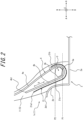
- FIG. 2 is a tire widthwise cross-sectional view illustrating an enlargement of the area near a bead portion 1c in the tire 1 illustrated in FIG. 1 when the tire 1 is mounted on an applicable rim 2.
- FIG. 2 illustrates the tire 1 as compressed and deformed in the tire radial direction, for example when traveling on a road surface.
- the applicable rim 2 of the present embodiment illustrated in FIG. 2 includes a rim seat portion 2a, to which the bead core 3, described below, of the tire 1 is attached on the outside in a tire radial direction B, and a rim flange portion 2b protruding outward in the tire radial direction B from both ends of the rim seat portion 2a in the tire width direction A.
- the bead portion 1c of the tire 1 is pressed inward in the tire width direction A by the rim flange portion 2b.
- the tire 1 includes a tread portion 1a, a pair of sidewall portions 1b extending from both ends of the tread portion 1a in the tire width direction A inward in the tire radial direction B, and a pair of bead portions 1c provided at the inner ends of the sidewall portions 1b in the tire radial direction B.
- the tire 1 is a radial tire and has a configuration suitable for use as a pneumatic tire for trucks, buses, and other heavy load vehicles.
- the "tread portion 1a" refers to the portion sandwiched by tread ends TE on both sides in the tire width direction A.
- the “bead portion 1c” refers to the portion in the tire radial direction B near where the below-described bead core 3 is located.
- the “sidewall portion 1b” refers to the portion between the tread portion 1a and the bead portion 1c.
- the “tread edge TE” refers to the outermost position of the contact patch in the tire width direction when the tire is mounted on the above-described applicable rim, filled to the above-described prescribed internal pressure, and placed under the maximum load.
- the outer surface of the tire includes the outer surface of the tread portion 1a, which is the surface on the outer side of the tread portion 1a in the tire radial direction B, the outer surface of the sidewall portion 1b, which is the surface on the outer side of the sidewall portion 1b in the tire width direction A, and the outer surface of the bead portion 1c, which is the surface on the outer side of the bead portion 1c in the tire width direction A.
- the tire outer surface is configured by a cover rubber 5 formed by tread rubber 10 and side rubber 11.
- the tire 1 includes the bead cores 3, a carcass ply 4, four layers of belt plies 6 to 9, tread rubber 10 and side rubber 11 as cover rubber 5, an inner liner 12, and a reinforcement layer 21.
- the bead core 3 is embedded in the bead portion 1c.
- the tire 1 may be further provided with a rubber bead filler located outward from the bead core 3 in the tire radial direction B.
- the bead core 3 includes a plurality of bead cords that are coated by rubber.
- the bead cords are formed by steel cords.
- the steel cords can, for example, be made of steel monofilaments or twisted wires.
- the carcass ply 4 extends toroidally to straddle the pair of bead portions 1c, more specifically to straddle the pair of bead cores 3.
- the carcass ply 4 of the present embodiment has a radial structure.
- the carcass ply 4 extends toroidally across the pair of bead cores 3 and is folded from inside to outside in the tire width direction A around each bead core 3.
- the carcass ply 4 includes a plurality of ply cords arranged in parallel to each other and coating rubber that covers the plurality of ply cords.
- the carcass ply 4 may be configured by, for example, arranging a plurality of ply cords that are made of brass, or plated with a material including brass, in parallel and bonding adjacent ply cords.
- the tire 1 in the present embodiment includes one carcass ply 4 but may instead include two or more carcass plies 4.
- the plurality of ply cords of the carcass ply 4 are arranged at an angle of, for example, 75° to 90° with respect to the tire circumferential direction C.
- the ply cords of the carcass ply 4 can be metal cords, such as steel cords.
- the steel cords can be made of steel monofilaments or twisted wires with, for example, a brass coating on the surface.
- the ply cords may also be organic fiber cords, for example, with a brass coating on the surface.
- the carcass ply 4 has a main body 4a located between the pair of bead cores 3 and a turn-up portion 4b that is formed by being connected to the main body 4a and turned up from inside to outside in the tire width direction A around each bead core 3.
- the tire 1 may further include a bead filler extending while tapering toward the outer side of the bead core 3 in the tire radial direction B.
- the bead filler is arranged between the main body 4a and the turn-up portion 4b of the carcass ply 4.
- the belt plies 6 to 9 are disposed in the tread portion 1a. Specifically, the belt plies 6 to 9 are disposed outside of the carcass ply 4 in the tire radial direction B relative to the crown of the carcass ply 4.
- the tire 1 in the present embodiment includes four layers of belt plies 6 to 9, but the number of layers is not particularly limited as long as at least one layer is provided.
- Each belt ply 6 to 9 includes a plurality of ply cords arranged in parallel to each other and coating rubber that covers the plurality of ply cords.
- each belt ply 6 to 9 may be configured by, for example, arranging a plurality of ply cords that are made of brass, or plated with a material including brass, in parallel and bonding adjacent ply cords.
- Each belt ply 6 to 9 forms a sloped belt layer in which the cord cut edges of the ply cords are exposed at both ends in the tire width direction A.
- the plurality of ply cords in each belt ply 6 to 9 extends at an angle with respect to the tire width direction A and the tire circumferential direction C.
- the ply cords are arranged to be inclined at an angle of 10° to 60° with respect to the tire circumferential direction C.
- the ply cords in each belt ply 6 to 9 can be metal cords, such as steel cords.
- the steel cords can be made of steel monofilaments or twisted wires with, for example, a brass coating on the surface.
- the ply cords may also be organic fiber cords, for example, with a brass coating on the surface.
- One or more of the four layers of belt plies 6 to 9 may be a circumferential belt layer that includes a plurality of ply cords extending along the tire circumferential direction C.
- the tread rubber 10 covers the crown portion of the main body 4a of the carcass ply 4 and covers the outer side, in the tire radial direction B, of the four layers of belt plies 6 to 9.
- the outer surface of the tread portion 1a in the present embodiment is configured by the tread rubber 10.
- a tread pattern including circumferential grooves extending in the tire circumferential direction C, widthwise grooves extending in the tire width direction A, and the like is formed on the outer surface of the tread portion 1a.
- the side rubber 11 covers the outside, in the tire width direction A, of the main body 4a and the turn-up portion 4b of the carcass ply 4.
- the outer surface of the sidewall portion 1b and the outer surface of the bead portion 1c in the present embodiment are configured by the side rubber 11.
- the outer end of the side rubber 11 in the tire radial direction B is connected to the end of the above-described tread rubber 10 in the tire width direction A.
- the tread rubber 10 and side rubber 11 in the present embodiment as a whole form the cover rubber 5 of the tire 1, which covers the carcass ply 4 and the belt plies 6 to 9 and configures the tire outer surface.
- the inner liner 12 covers the tire inner surface side of the main body 4a of the carcass ply 4 and configures the tire inner surface of the tire 1.
- the inner liner 12 is layered onto the tire inner surface side of the main body 4a of the carcass ply 4.
- the inner liner 12 may, for example, be formed from a butyl-based rubber having low air permeability.
- Butyl-based rubber refers to butyl rubber and butyl halide rubber, which is a derivative thereof.
- the reinforcement layer 21 is located inward from the tire outer surface of the side rubber 11 of the cover rubber 5 and covers an outer side, in the tire width direction A, of at least a portion of the turn-up portion 4b of the carcass ply 4. Therefore, as illustrated in FIG. 2 , even if the bead portion 1c of the tire 1 is pressed by the rim flange portion 2b, and the cover rubber 5 between the rim flange portion 2b and the turn-up portion 4b of the carcass ply 4 is compressed and deformed, the concentration of shear strain along the turn-up portion 4b in the cover rubber 5 near the turn-up portion 4b can be suppressed. As illustrated in FIG.
- the reinforcement layer 21 is configured by a non-woven fabric formed from metal fibers 22.
- the modulus of the reinforcement layer 21 in the cord extension direction D of the ply cords of the turn-up portion 4b in the carcass ply 4 is lower than the modulus of the turn-up portion 4b in the cord extension direction D.
- the use of such a reinforcement layer 21 can maintain flexibility while improving the adhesiveness with the side rubber 11 as the surrounding cover rubber 5. Therefore, the concentration of shear strain along the reinforcement layer 21 can also be suppressed for the cover rubber 5 near the reinforcement layer 21.
- the reinforcement layer 21 is located in a region RA, in the tire radial direction B, that is from 5% to 30% of the tire section height SH from an inner edge 3a of the bead core 3 in the tire radial direction B outward in the tire radial direction B.
- the tire section height SH is the length in the tire radial direction B, in the tire widthwise cross-section, from the inner edge 3a of the bead core 3 in the tire radial direction B to the outer edge of the tread rubber 10 in the tire radial direction B (in the present embodiment, the position of the tire equatorial plane CL in the tire width direction A).
- the entire reinforcement layer 21 is prevented from moving together with the cover rubber 5 along the cord extension direction D of the ply cords of the turn-up portion 4b. Consequently, the concentration of shear strain along the reinforcement layer 21 can be better suppressed at the cover rubber 5 near the reinforcement layer 21.
- At least a portion of the reinforcement layer 21 is preferably located farther inward in the tire radial direction B than the position of the outer edge 2b1 of the rim flange portion 2b in the tire radial direction B.
- the reinforcement layer 21 preferably extends from a position farther outward, in the tire radial direction B, than the outer edge 3b of the bead core 3 in the tire radial direction B to a position farther inward on the outer side, in the tire width direction A, of the turn-up portion 4b.
- the reinforcement main body 21a that is located farther outward in the tire width direction A than the turn-up portion 4b of the carcass ply 4 preferably extends in the tire radial direction B across a position P2, in the tire radial direction B, of the outer edge 3b of the bead core 3.
- the reinforcement layer 21 is turned up around the bead core 3 from the outer side towards the inner side in the tire width direction A.
- the portion of the reinforcement main body 21a in the tire radial direction B located father outward in the tire width direction A than the turn-up portion 4b of the carcass ply 4 is preferably wrapped around the bead core 3 and is preferably wrapped up farther outward, in the tire radial direction B, than a position P1, in the tire radial direction B, of the inner edge 3a of the bead core 3.
- the reinforcement layer 21 can be further prevented from moving together with the cover rubber 5 along the cord extension direction D of the ply cords of the turn-up portion 4b. Consequently, the concentration of shear strain along the reinforcement layer 21 can be better suppressed at the cover rubber 5 near the reinforcement layer 21.
- the reinforcement main body 21a formed by being turned up around the bead core 3 from the outer side towards the inner side in the tire width direction A is more preferably wrapped up farther outward, in the tire radial direction B, than the outer edge 3b of the bead core 3 in the tire widthwise cross-sectional view (see FIG. 2 ).
- the reinforcement layer 21 is even further prevented from moving together with the cover rubber 5 along the cord extension direction D of the ply cords of the turn-up portion 4b. Therefore, the concentration of shear strain along the reinforcement layer 21 can be even further suppressed at the cover rubber 5 near the reinforcement layer 21.
- the reinforcement layer 21 configured by a non-woven fabric formed from metal fibers 22 can be manufactured by various methods, and the manufacturing method is not limited.
- a needle punch can be used to entangle metal fibers 22, obtained by various cutting methods, into a felt-like shape.
- the diameter of the metal fibers 22 can be changed by changing the amount of cutting, for example.
- the thickness and density of the non-woven fabric formed from the metal fibers 22 can be changed by, for example, changing the amount of metal fibers 22 that are punched and changing the number of vertical movements per unit time during needle punching.
- the reinforcement layer 21 in the present embodiment is configured by a non-woven fabric formed from metal fibers 22.
- the edges of the metal fibers 22 tend not to be exposed on the outer surface of the reinforcement layer 21, and the occurrence of cracks in the surrounding rubber can be suppressed.
- FIG. 3A is a cross-sectional view of the metal fiber 22 configuring the reinforcement layer 21.
- the metal fiber 22 is configured by steel, copper, aluminum, nickel, or an alloy including any of these.
- the metal fiber 22 illustrated in FIG. 3A is formed from a wire 41 composed of the above-described metal materials.
- the metal fibers 22 configuring the reinforcement layer 21 are preferably formed from brass. In this way, the adhesiveness to the surrounding cover rubber 5 is enhanced as compared not only to organic fibers but also to metal fibers formed from the other metal materials described above, and the concentration of sheer stress at the cover rubber 5 near the reinforcement layer 21 can be further suppressed.
- the surface of the metal fiber 22 can be configured as a coating film 33 formed from a binary alloy of copper and zinc, or a ternary alloy of copper, zinc, and cobalt, as illustrated in FIG. 3B .
- the metal fiber 22 illustrated in FIG. 3B is configured by a wire 42 as the base material and a coating film 43 laminated on the surface of the wire 42.
- the method of forming such a film 43 is not particularly limited but may, for example, be electrolytic treatment by binary alloy plating or ternary alloy plating, or a method of alloying by heat treatment after penetrating in copper plating and zinc plating baths to perform laminated plating treatment.
- the density of the non-woven fabric configuring the reinforcement layer 21 is preferably 100 g/m 2 to 900 g/m 2 and in particular is preferably 200 g/m 2 to 600 g/m 2 .
- the density of the non-woven fabric configuring the reinforcement layer 21 refers to the mass per unit area as measured in accordance with ISO 9073-1. Specifically, the density of the non-woven fabric configuring the reinforcement layer 21 can be calculated by removing the non-woven fabric from the tire 1, melting or incinerating the rubber to remove the rubber, and then weighing the non-woven fabric itself and calculating the density.
- the diameter of the filament configuring the reinforcement layer 21 is preferably 10 ⁇ m to 75 ⁇ m and in particular is preferably 20 ⁇ m to 50 ⁇ m.
- the area may be replaced by the circular area. In this way, the durability of the tire 1 can be further enhanced, and an excessive increase in weight of the tire 1 can be also suppressed, for the same reasons as for the above-described density of the non-woven fabric.
- the reinforcement layer 21 and the ply preferably overlap by 10 mm or more in a ply extension direction orthogonal to the ply thickness direction.
- the reinforcement layer 21 and the turn-up portion 4b of the carcass ply 4 in the present embodiment have an overlap region L of 10 mm or more in the carcass ply extension direction (the same direction as the cord extension direction D of the ply cords of the turn-up portion 4b) that is orthogonal to the carcass ply thickness direction.
- the overlap region L is more preferably 20 mm to 60 mm.
- the extending length of the reinforcement layer 21 along the turn-up portion 4b of the carcass ply 4 is preferably 10 mm or more, more preferably 20 mm or more, and in particular preferably 30 mm or more.
- the reinforcement layer 21 is more easily sandwiched between the rim flange portion 2b and the turn-up portion 4b of the carcass ply 4.
- the extending length of the reinforcement layer 21 along the turn-up portion 4b of the carcass ply 4 is preferably 80 mm or less.
- the outer edge 21a1, in the tire radial direction B, of the reinforcement layer 21 of the present embodiment is located father inward in the tire radial direction B than the outer edge 4b1 of the turn-up portion 4b in the tire radial direction B, but this configuration is not limiting.
- FIG. 4 illustrates a reinforcement layer 121 as a variation of the reinforcement layer 21.
- the outer edge 21a1 of the reinforcement layer 121 in the tire radial direction B may be located father outward in the tire radial direction B than the outer edge 4b1 of the turn-up portion 4b in the tire radial direction B.
- the reinforcement layer 121 covers the outer edge 4b1 of the turn-up portion 4b from the outer side in the tire width direction A, thereby relieving the stress concentration due to the difference in rigidity from the surrounding cover rubber 5 at the position of the outer edge 4b1 of the turn-up portion 4b.
- the reinforcement layer 121 illustrated in FIG. 4 not only covers the outer edge 4b1 of the turn-up portion 4b from the outer side in the tire width direction A but is also turned up in a U-shape so as to cover the outer edge 4b1 from both the outer side in the tire radial direction B and the inner side in the tire width direction A.
- this configuration is not limiting.
- the first test piece was a test piece in which nothing was disposed along the steel fibers ("Test piece X1" in Table 1 below).
- the second test piece was a test piece in which organic fibers were disposed along the steel fibers ("Test piece X2" in Table 1 below).
- the organic fibers used were nylon 6, with a mass of 470 dtex/1, and a number of embedded fibers equivalent to 78 fibers/5 cm.
- the third test piece was a test piece in which a brass non-woven fabric was disposed along the steel fibers ("Test piece X3" in Table 1 below).
- the brass used was C2680, the filament diameter of the non-woven fabric was 25 ⁇ m, and the density was 300 g/m 2 .
- Reinforcement Crack length (index) Test piece X1 none 1.0
- Test piece X3 brass non-woven fabric 0.4
- the present invention relates to a pneumatic tire.
Landscapes
- Engineering & Computer Science (AREA)
- Mechanical Engineering (AREA)
- Tires In General (AREA)
Claims (9)
- Bandage pneumatique (1), comprenant :une paire de tringles (3) ;une nappe de carcasse (4) comprenant un corps principal (4a) positionné entre les tringles et une partie retournée (4b) connectée au corps principal et formée en la retournant autour de chaque tringle, de l'intérieur vers l'extérieur, dans une direction de la largeur du pneumatique (A) ;une gomme de couverture (5) recouvrant le corps principal de la nappe de carcasse et un côté externe de la partie retournée, dans la direction de la largeur du pneumatique, et configurant une surface externe du pneumatique ; etune couche de renforcement (21, 121) qui se situe vers l'intérieur par rapport à la surface externe du pneumatique de la gomme de couverture et recouvre un côté externe, dans la direction de la largeur du pneumatique, d'au moins une partie de la partie retournée de la nappe de carcasse, dans lequel :la couche de renforcement est configurée par un tissu non tissé formé à partir de fibres métalliques (22) ;dans lequel, dans une vue en section transversale dans le sens de la largeur du pneumatique, au moins une partie de la couche de renforcement est disposée dans une région (RA), dans une direction radiale du pneumatique, représentant 5 % à 30 % d'une hauteur de section du pneumatique, d'un bord interne de la tringle, dans la direction radiale du pneumatique, vers l'extérieur, dans la direction radiale du pneumatique ;dans lequel, dans la vue en section transversale dans le sens de la largeur du pneumatique, la couche de renforcement s'étend à partir d'une position située davantage vers l'extérieur, dans la direction radiale du pneumatique, qu'un bord externe de la tringle, dans la direction radiale du pneumatique, vers une position située davantage vers l'intérieur ; etdans lequel, dans la vue en section transversale dans le sens de la largeur du pneumatique, la couche de renforcement est retournée autour de la tringle, d'un côté externe vers un côté interne, dans la direction de la largeur du pneumatique.
- Bandage pneumatique (1) selon la revendication 1, dans lequel les fibres métalliques (22) comprennent de l'acier, du cuivre, de l'aluminium, du nickel ou un alliage incluant un quelconque de ceux-ci.
- Bandage pneumatique (1) selon la revendication 2, dans lequel les fibres métalliques (22) comprennent du laiton.
- Bandage pneumatique (1) selon l'une quelconque des revendications précédentes, dans lequel une surface des fibres métalliques (22) est configurée par un film de revêtement (43) comprenant un alliage binaire de cuivre et de zinc, ou un alliage ternaire de cuivre, de zinc et de cobalt.
- Bandage pneumatique (1) selon l'une quelconque des revendications précédentes, dans lequel une densité du tissu non tissé est comprise entre 100 g/m2 et 900 g/m2.
- Bandage pneumatique (1) selon l'une quelconque des revendications précédentes, dans lequel un diamètre de filament du tissu non tissé est compris entre 10 µm et 75 µm.
- Bandage pneumatique (1) selon l'une quelconque des revendications précédentes, dans lequel, dans une vue en section transversale dans le sens de la largeur du pneumatique, la couche de renforcement (22) et la partie retournée (4b) de la nappe de carcasse (4) se chevauchent sur 10 mm ou plus le long d'une direction d'extension de la nappe orthogonale à une direction de l'épaisseur de la nappe.
- Bandage pneumatique (1) selon l'une quelconque des revendications précédentes, dans lequel la couche de renforcement (121) a une forme en U et recouvre un bord externe (4b1) de la partie retournée (4b) à partir d'un côté externe, dans la direction radiale du pneumatique, (B), et d'un côté interne, dans la direction de la largeur du pneumatique (A).
- Bandage pneumatique (1) selon l'une quelconque des revendications précédentes, dans lequel un module de la couche de renforcement (21), dans une direction d'extension des câblés (D) de câblés de la nappe de la partie retournée (4b), est inférieur à un module de la partie retournée (4b) dans la direction d'extension des câblés (D).
Applications Claiming Priority (2)
| Application Number | Priority Date | Filing Date | Title |
|---|---|---|---|
| JP2020092586A JP7333289B2 (ja) | 2020-05-27 | 2020-05-27 | 空気入りタイヤ |
| PCT/JP2021/000566 WO2021240863A1 (fr) | 2020-05-27 | 2021-01-08 | Pneumatique |
Publications (3)
| Publication Number | Publication Date |
|---|---|
| EP4159480A1 EP4159480A1 (fr) | 2023-04-05 |
| EP4159480A4 EP4159480A4 (fr) | 2023-12-27 |
| EP4159480B1 true EP4159480B1 (fr) | 2025-04-16 |
Family
ID=78744184
Family Applications (1)
| Application Number | Title | Priority Date | Filing Date |
|---|---|---|---|
| EP21812215.8A Active EP4159480B1 (fr) | 2020-05-27 | 2021-01-08 | Pneumatique |
Country Status (5)
| Country | Link |
|---|---|
| US (1) | US20230271460A1 (fr) |
| EP (1) | EP4159480B1 (fr) |
| JP (1) | JP7333289B2 (fr) |
| CN (1) | CN115485151B (fr) |
| WO (1) | WO2021240863A1 (fr) |
Citations (2)
| Publication number | Priority date | Publication date | Assignee | Title |
|---|---|---|---|---|
| JP2012106531A (ja) * | 2010-11-15 | 2012-06-07 | Sumitomo Rubber Ind Ltd | 重荷重用タイヤ |
| JP2016049920A (ja) * | 2014-09-01 | 2016-04-11 | 株式会社ブリヂストン | タイヤ |
Family Cites Families (28)
| Publication number | Priority date | Publication date | Assignee | Title |
|---|---|---|---|---|
| US3095027A (en) * | 1959-10-12 | 1963-06-25 | Firestone Tire & Rubber Co | Pneumatic tire |
| GB1472745A (en) * | 1973-06-26 | 1977-05-04 | Dunlop Ltd | Pneumatic tyres |
| JP3673026B2 (ja) * | 1996-09-03 | 2005-07-20 | 住友ゴム工業株式会社 | 空気入りタイヤ |
| WO1998054011A1 (fr) * | 1997-05-26 | 1998-12-03 | Bridgestone Corporation | Pneumatique de securite |
| US6209604B1 (en) * | 1997-12-22 | 2001-04-03 | Bridgestone Corporation | Pneumatic tire for passenger cars with sidewall portions having a rubber reinforcing layer and a rubber-filament fiber composite |
| JP4293658B2 (ja) * | 1998-11-11 | 2009-07-08 | 株式会社ブリヂストン | 重荷重用空気入りラジアルタイヤ |
| JP2001287282A (ja) * | 2000-04-07 | 2001-10-16 | Bridgestone Corp | タイヤの製造方法及びタイヤ |
| JP2005153591A (ja) * | 2003-11-21 | 2005-06-16 | Sumitomo Rubber Ind Ltd | 不整地用モーターサイクルタイヤ |
| JP2005271638A (ja) * | 2004-03-23 | 2005-10-06 | Bridgestone Corp | 空気入りタイヤ |
| JP2006199087A (ja) * | 2005-01-19 | 2006-08-03 | Bridgestone Corp | 空気入りタイヤ及びその製造方法 |
| JP2006347394A (ja) | 2005-06-16 | 2006-12-28 | Sumitomo Rubber Ind Ltd | 空気入りタイヤ |
| KR101059333B1 (ko) * | 2006-10-20 | 2011-08-24 | 가부시키가이샤 브리지스톤 | 공기입 타이어 |
| WO2011142389A1 (fr) * | 2010-05-11 | 2011-11-17 | 株式会社ブリヂストン | Pneumatique |
| JP5893824B2 (ja) * | 2010-08-30 | 2016-03-23 | 横浜ゴム株式会社 | 空気入りラジアルタイヤ |
| JP6194151B2 (ja) * | 2011-01-19 | 2017-09-06 | 株式会社ブリヂストン | 空気入りタイヤ |
| JP2012245655A (ja) | 2011-05-25 | 2012-12-13 | Bridgestone Corp | 空気入りタイヤの製造方法および空気入りタイヤ |
| JP6013908B2 (ja) * | 2012-12-28 | 2016-10-25 | 住友ゴム工業株式会社 | 重荷重用タイヤ |
| JP6087776B2 (ja) * | 2013-09-24 | 2017-03-01 | 東洋ゴム工業株式会社 | 空気入りセミラジアルタイヤ |
| JP2015227138A (ja) * | 2014-06-02 | 2015-12-17 | 株式会社ブリヂストン | 空気入りタイヤ |
| JP6293602B2 (ja) * | 2014-07-17 | 2018-03-14 | 東洋ゴム工業株式会社 | 空気入りタイヤ及びその製造方法 |
| JP6509519B2 (ja) | 2014-10-08 | 2019-05-08 | Toyo Tire株式会社 | 空気入りタイヤ |
| JP2016165923A (ja) | 2015-03-09 | 2016-09-15 | 株式会社ブリヂストン | 空気入りタイヤ |
| JP6742890B2 (ja) * | 2016-11-28 | 2020-08-19 | Toyo Tire株式会社 | 空気入りタイヤ |
| JP6790845B2 (ja) * | 2017-01-13 | 2020-11-25 | 住友ゴム工業株式会社 | 重荷重用空気入りタイヤ |
| JP6930262B2 (ja) * | 2017-07-18 | 2021-09-01 | 横浜ゴム株式会社 | 空気入りタイヤ及び空気入りタイヤの製造方法 |
| JP6921668B2 (ja) | 2017-07-19 | 2021-08-18 | 株式会社ブリヂストン | 空気入りタイヤ |
| JP2020037330A (ja) * | 2018-09-04 | 2020-03-12 | 株式会社ブリヂストン | 空気入りタイヤ |
| JP7323490B2 (ja) * | 2020-05-27 | 2023-08-08 | 株式会社ブリヂストン | 空気入りタイヤ |
-
2020
- 2020-05-27 JP JP2020092586A patent/JP7333289B2/ja active Active
-
2021
- 2021-01-08 WO PCT/JP2021/000566 patent/WO2021240863A1/fr not_active Ceased
- 2021-01-08 US US17/997,660 patent/US20230271460A1/en active Pending
- 2021-01-08 EP EP21812215.8A patent/EP4159480B1/fr active Active
- 2021-01-08 CN CN202180032142.4A patent/CN115485151B/zh active Active
Patent Citations (2)
| Publication number | Priority date | Publication date | Assignee | Title |
|---|---|---|---|---|
| JP2012106531A (ja) * | 2010-11-15 | 2012-06-07 | Sumitomo Rubber Ind Ltd | 重荷重用タイヤ |
| JP2016049920A (ja) * | 2014-09-01 | 2016-04-11 | 株式会社ブリヂストン | タイヤ |
Also Published As
| Publication number | Publication date |
|---|---|
| CN115485151B (zh) | 2024-05-03 |
| CN115485151A (zh) | 2022-12-16 |
| EP4159480A4 (fr) | 2023-12-27 |
| EP4159480A1 (fr) | 2023-04-05 |
| JP7333289B2 (ja) | 2023-08-24 |
| WO2021240863A1 (fr) | 2021-12-02 |
| US20230271460A1 (en) | 2023-08-31 |
| JP2021187237A (ja) | 2021-12-13 |
Similar Documents
| Publication | Publication Date | Title |
|---|---|---|
| EP3059102B1 (fr) | Pneumatique | |
| EP2796300B1 (fr) | Pneumatique pour charges lourdes | |
| JP5312233B2 (ja) | 空気入りタイヤ | |
| EP2818332B1 (fr) | Pneumatique | |
| EP3459763B1 (fr) | Pneumatique | |
| EP2910391B1 (fr) | Enveloppe pneumatique | |
| JP2017074834A (ja) | 空気入りタイヤ | |
| EP4159481B1 (fr) | Bandage pneumatique | |
| US20210394563A1 (en) | Tire | |
| JP6015450B2 (ja) | 空気入りタイヤ | |
| EP2853419B1 (fr) | Pneu | |
| US9440406B2 (en) | Pneumatic tire and method of forming circumferential belt layer of the same | |
| EP2610074A1 (fr) | Pneu d'aéronef à carcasse radiale | |
| EP2803505B1 (fr) | Pneu très résistant | |
| EP3805016A1 (fr) | Pneu | |
| JP3116044B2 (ja) | 重荷重、小型トラック用の空気入りタイヤ | |
| EP4159480B1 (fr) | Pneumatique | |
| JP2014118011A (ja) | 空気入りタイヤ | |
| JP2026015990A (ja) | タイヤ | |
| CN118541270A (zh) | 耐负载的车辆充气轮胎 | |
| JP2004345501A (ja) | 空気入りタイヤ | |
| JP2007203805A (ja) | 空気入りタイヤ | |
| CN112912260A (zh) | 充气轮胎 | |
| JP2011245999A (ja) | 空気入りタイヤ |
Legal Events
| Date | Code | Title | Description |
|---|---|---|---|
| STAA | Information on the status of an ep patent application or granted ep patent |
Free format text: STATUS: THE INTERNATIONAL PUBLICATION HAS BEEN MADE |
|
| PUAI | Public reference made under article 153(3) epc to a published international application that has entered the european phase |
Free format text: ORIGINAL CODE: 0009012 |
|
| STAA | Information on the status of an ep patent application or granted ep patent |
Free format text: STATUS: REQUEST FOR EXAMINATION WAS MADE |
|
| 17P | Request for examination filed |
Effective date: 20221125 |
|
| AK | Designated contracting states |
Kind code of ref document: A1 Designated state(s): AL AT BE BG CH CY CZ DE DK EE ES FI FR GB GR HR HU IE IS IT LI LT LU LV MC MK MT NL NO PL PT RO RS SE SI SK SM TR |
|
| DAV | Request for validation of the european patent (deleted) | ||
| DAX | Request for extension of the european patent (deleted) | ||
| A4 | Supplementary search report drawn up and despatched |
Effective date: 20231123 |
|
| RIC1 | Information provided on ipc code assigned before grant |
Ipc: B60C 15/06 20060101ALI20231117BHEP Ipc: B60C 9/00 20060101AFI20231117BHEP |
|
| STAA | Information on the status of an ep patent application or granted ep patent |
Free format text: STATUS: EXAMINATION IS IN PROGRESS |
|
| 17Q | First examination report despatched |
Effective date: 20240702 |
|
| GRAP | Despatch of communication of intention to grant a patent |
Free format text: ORIGINAL CODE: EPIDOSNIGR1 |
|
| STAA | Information on the status of an ep patent application or granted ep patent |
Free format text: STATUS: GRANT OF PATENT IS INTENDED |
|
| INTG | Intention to grant announced |
Effective date: 20250113 |
|
| GRAS | Grant fee paid |
Free format text: ORIGINAL CODE: EPIDOSNIGR3 |
|
| GRAA | (expected) grant |
Free format text: ORIGINAL CODE: 0009210 |
|
| STAA | Information on the status of an ep patent application or granted ep patent |
Free format text: STATUS: THE PATENT HAS BEEN GRANTED |
|
| AK | Designated contracting states |
Kind code of ref document: B1 Designated state(s): AL AT BE BG CH CY CZ DE DK EE ES FI FR GB GR HR HU IE IS IT LI LT LU LV MC MK MT NL NO PL PT RO RS SE SI SK SM TR |
|
| REG | Reference to a national code |
Ref country code: GB Ref legal event code: FG4D |
|
| P01 | Opt-out of the competence of the unified patent court (upc) registered |
Free format text: CASE NUMBER: APP_14607/2025 Effective date: 20250325 |
|
| REG | Reference to a national code |
Ref country code: CH Ref legal event code: EP |
|
| REG | Reference to a national code |
Ref country code: IE Ref legal event code: FG4D |
|
| REG | Reference to a national code |
Ref country code: DE Ref legal event code: R096 Ref document number: 602021029329 Country of ref document: DE |
|
| REG | Reference to a national code |
Ref country code: NL Ref legal event code: MP Effective date: 20250416 |
|
| PG25 | Lapsed in a contracting state [announced via postgrant information from national office to epo] |
Ref country code: NL Free format text: LAPSE BECAUSE OF FAILURE TO SUBMIT A TRANSLATION OF THE DESCRIPTION OR TO PAY THE FEE WITHIN THE PRESCRIBED TIME-LIMIT Effective date: 20250416 |
|
| REG | Reference to a national code |
Ref country code: AT Ref legal event code: MK05 Ref document number: 1785358 Country of ref document: AT Kind code of ref document: T Effective date: 20250416 |
|
| PG25 | Lapsed in a contracting state [announced via postgrant information from national office to epo] |
Ref country code: FI Free format text: LAPSE BECAUSE OF FAILURE TO SUBMIT A TRANSLATION OF THE DESCRIPTION OR TO PAY THE FEE WITHIN THE PRESCRIBED TIME-LIMIT Effective date: 20250416 Ref country code: PT Free format text: LAPSE BECAUSE OF FAILURE TO SUBMIT A TRANSLATION OF THE DESCRIPTION OR TO PAY THE FEE WITHIN THE PRESCRIBED TIME-LIMIT Effective date: 20250818 Ref country code: ES Free format text: LAPSE BECAUSE OF FAILURE TO SUBMIT A TRANSLATION OF THE DESCRIPTION OR TO PAY THE FEE WITHIN THE PRESCRIBED TIME-LIMIT Effective date: 20250416 |
|
| REG | Reference to a national code |
Ref country code: LT Ref legal event code: MG9D |
|
| PG25 | Lapsed in a contracting state [announced via postgrant information from national office to epo] |
Ref country code: NO Free format text: LAPSE BECAUSE OF FAILURE TO SUBMIT A TRANSLATION OF THE DESCRIPTION OR TO PAY THE FEE WITHIN THE PRESCRIBED TIME-LIMIT Effective date: 20250716 Ref country code: GR Free format text: LAPSE BECAUSE OF FAILURE TO SUBMIT A TRANSLATION OF THE DESCRIPTION OR TO PAY THE FEE WITHIN THE PRESCRIBED TIME-LIMIT Effective date: 20250717 |
|
| PG25 | Lapsed in a contracting state [announced via postgrant information from national office to epo] |
Ref country code: PL Free format text: LAPSE BECAUSE OF FAILURE TO SUBMIT A TRANSLATION OF THE DESCRIPTION OR TO PAY THE FEE WITHIN THE PRESCRIBED TIME-LIMIT Effective date: 20250416 |
|
| PG25 | Lapsed in a contracting state [announced via postgrant information from national office to epo] |
Ref country code: BG Free format text: LAPSE BECAUSE OF FAILURE TO SUBMIT A TRANSLATION OF THE DESCRIPTION OR TO PAY THE FEE WITHIN THE PRESCRIBED TIME-LIMIT Effective date: 20250416 |
|
| PG25 | Lapsed in a contracting state [announced via postgrant information from national office to epo] |
Ref country code: HR Free format text: LAPSE BECAUSE OF FAILURE TO SUBMIT A TRANSLATION OF THE DESCRIPTION OR TO PAY THE FEE WITHIN THE PRESCRIBED TIME-LIMIT Effective date: 20250416 |
|
| PG25 | Lapsed in a contracting state [announced via postgrant information from national office to epo] |
Ref country code: AT Free format text: LAPSE BECAUSE OF FAILURE TO SUBMIT A TRANSLATION OF THE DESCRIPTION OR TO PAY THE FEE WITHIN THE PRESCRIBED TIME-LIMIT Effective date: 20250416 |
|
| PG25 | Lapsed in a contracting state [announced via postgrant information from national office to epo] |
Ref country code: RS Free format text: LAPSE BECAUSE OF FAILURE TO SUBMIT A TRANSLATION OF THE DESCRIPTION OR TO PAY THE FEE WITHIN THE PRESCRIBED TIME-LIMIT Effective date: 20250716 |
|
| PG25 | Lapsed in a contracting state [announced via postgrant information from national office to epo] |
Ref country code: IS Free format text: LAPSE BECAUSE OF FAILURE TO SUBMIT A TRANSLATION OF THE DESCRIPTION OR TO PAY THE FEE WITHIN THE PRESCRIBED TIME-LIMIT Effective date: 20250816 |
|
| PG25 | Lapsed in a contracting state [announced via postgrant information from national office to epo] |
Ref country code: LV Free format text: LAPSE BECAUSE OF FAILURE TO SUBMIT A TRANSLATION OF THE DESCRIPTION OR TO PAY THE FEE WITHIN THE PRESCRIBED TIME-LIMIT Effective date: 20250416 |
|
| PG25 | Lapsed in a contracting state [announced via postgrant information from national office to epo] |
Ref country code: SM Free format text: LAPSE BECAUSE OF FAILURE TO SUBMIT A TRANSLATION OF THE DESCRIPTION OR TO PAY THE FEE WITHIN THE PRESCRIBED TIME-LIMIT Effective date: 20250416 Ref country code: DK Free format text: LAPSE BECAUSE OF FAILURE TO SUBMIT A TRANSLATION OF THE DESCRIPTION OR TO PAY THE FEE WITHIN THE PRESCRIBED TIME-LIMIT Effective date: 20250416 |
|
| REG | Reference to a national code |
Ref country code: DE Ref legal event code: R097 Ref document number: 602021029329 Country of ref document: DE |
|
| PG25 | Lapsed in a contracting state [announced via postgrant information from national office to epo] |
Ref country code: CZ Free format text: LAPSE BECAUSE OF FAILURE TO SUBMIT A TRANSLATION OF THE DESCRIPTION OR TO PAY THE FEE WITHIN THE PRESCRIBED TIME-LIMIT Effective date: 20250416 |
|
| PG25 | Lapsed in a contracting state [announced via postgrant information from national office to epo] |
Ref country code: EE Free format text: LAPSE BECAUSE OF FAILURE TO SUBMIT A TRANSLATION OF THE DESCRIPTION OR TO PAY THE FEE WITHIN THE PRESCRIBED TIME-LIMIT Effective date: 20250416 |
|
| PG25 | Lapsed in a contracting state [announced via postgrant information from national office to epo] |
Ref country code: SK Free format text: LAPSE BECAUSE OF FAILURE TO SUBMIT A TRANSLATION OF THE DESCRIPTION OR TO PAY THE FEE WITHIN THE PRESCRIBED TIME-LIMIT Effective date: 20250416 |
|
| PG25 | Lapsed in a contracting state [announced via postgrant information from national office to epo] |
Ref country code: IT Free format text: LAPSE BECAUSE OF FAILURE TO SUBMIT A TRANSLATION OF THE DESCRIPTION OR TO PAY THE FEE WITHIN THE PRESCRIBED TIME-LIMIT Effective date: 20250416 |
|
| PLBE | No opposition filed within time limit |
Free format text: ORIGINAL CODE: 0009261 |
|
| STAA | Information on the status of an ep patent application or granted ep patent |
Free format text: STATUS: NO OPPOSITION FILED WITHIN TIME LIMIT |
|
| REG | Reference to a national code |
Ref country code: CH Ref legal event code: L10 Free format text: ST27 STATUS EVENT CODE: U-0-0-L10-L00 (AS PROVIDED BY THE NATIONAL OFFICE) Effective date: 20260225 |
|
| 26N | No opposition filed |
Effective date: 20260119 |
|
| PGFP | Annual fee paid to national office [announced via postgrant information from national office to epo] |
Ref country code: DE Payment date: 20260121 Year of fee payment: 6 |
|
| PGFP | Annual fee paid to national office [announced via postgrant information from national office to epo] |
Ref country code: FR Payment date: 20260123 Year of fee payment: 6 |