EP4153874B1 - Werkzeugloses anzugselement und zugehöriger verbindungsbeschlag - Google Patents
Werkzeugloses anzugselement und zugehöriger verbindungsbeschlag Download PDFInfo
- Publication number
- EP4153874B1 EP4153874B1 EP21722813.9A EP21722813A EP4153874B1 EP 4153874 B1 EP4153874 B1 EP 4153874B1 EP 21722813 A EP21722813 A EP 21722813A EP 4153874 B1 EP4153874 B1 EP 4153874B1
- Authority
- EP
- European Patent Office
- Prior art keywords
- housing
- folded
- tightening element
- furniture
- end position
- Prior art date
- Legal status (The legal status is an assumption and is not a legal conclusion. Google has not performed a legal analysis and makes no representation as to the accuracy of the status listed.)
- Active
Links
Images


Classifications
-
- F—MECHANICAL ENGINEERING; LIGHTING; HEATING; WEAPONS; BLASTING
- F16—ENGINEERING ELEMENTS AND UNITS; GENERAL MEASURES FOR PRODUCING AND MAINTAINING EFFECTIVE FUNCTIONING OF MACHINES OR INSTALLATIONS; THERMAL INSULATION IN GENERAL
- F16B—DEVICES FOR FASTENING OR SECURING CONSTRUCTIONAL ELEMENTS OR MACHINE PARTS TOGETHER, e.g. NAILS, BOLTS, CIRCLIPS, CLAMPS, CLIPS OR WEDGES; JOINTS OR JOINTING
- F16B12/00—Jointing of furniture or the like, e.g. hidden from exterior
- F16B12/10—Jointing of furniture or the like, e.g. hidden from exterior using pegs, bolts, tenons, clamps, clips, or the like
- F16B12/12—Jointing of furniture or the like, e.g. hidden from exterior using pegs, bolts, tenons, clamps, clips, or the like for non-metal furniture parts, e.g. made of wood, of plastics
- F16B12/20—Jointing of furniture or the like, e.g. hidden from exterior using pegs, bolts, tenons, clamps, clips, or the like for non-metal furniture parts, e.g. made of wood, of plastics using clamps, clips, wedges, sliding bolts, or the like
- F16B12/2009—Jointing of furniture or the like, e.g. hidden from exterior using pegs, bolts, tenons, clamps, clips, or the like for non-metal furniture parts, e.g. made of wood, of plastics using clamps, clips, wedges, sliding bolts, or the like actuated by rotary motion
-
- F—MECHANICAL ENGINEERING; LIGHTING; HEATING; WEAPONS; BLASTING
- F16—ENGINEERING ELEMENTS AND UNITS; GENERAL MEASURES FOR PRODUCING AND MAINTAINING EFFECTIVE FUNCTIONING OF MACHINES OR INSTALLATIONS; THERMAL INSULATION IN GENERAL
- F16B—DEVICES FOR FASTENING OR SECURING CONSTRUCTIONAL ELEMENTS OR MACHINE PARTS TOGETHER, e.g. NAILS, BOLTS, CIRCLIPS, CLAMPS, CLIPS OR WEDGES; JOINTS OR JOINTING
- F16B12/00—Jointing of furniture or the like, e.g. hidden from exterior
- F16B12/10—Jointing of furniture or the like, e.g. hidden from exterior using pegs, bolts, tenons, clamps, clips, or the like
- F16B12/12—Jointing of furniture or the like, e.g. hidden from exterior using pegs, bolts, tenons, clamps, clips, or the like for non-metal furniture parts, e.g. made of wood, of plastics
- F16B12/20—Jointing of furniture or the like, e.g. hidden from exterior using pegs, bolts, tenons, clamps, clips, or the like for non-metal furniture parts, e.g. made of wood, of plastics using clamps, clips, wedges, sliding bolts, or the like
- F16B12/2009—Jointing of furniture or the like, e.g. hidden from exterior using pegs, bolts, tenons, clamps, clips, or the like for non-metal furniture parts, e.g. made of wood, of plastics using clamps, clips, wedges, sliding bolts, or the like actuated by rotary motion
- F16B12/2027—Jointing of furniture or the like, e.g. hidden from exterior using pegs, bolts, tenons, clamps, clips, or the like for non-metal furniture parts, e.g. made of wood, of plastics using clamps, clips, wedges, sliding bolts, or the like actuated by rotary motion with rotating excenters or wedges
- F16B12/2036—Jointing of furniture or the like, e.g. hidden from exterior using pegs, bolts, tenons, clamps, clips, or the like for non-metal furniture parts, e.g. made of wood, of plastics using clamps, clips, wedges, sliding bolts, or the like actuated by rotary motion with rotating excenters or wedges with rotating excenters or wedges acting on a head of a pin or screw
-
- F—MECHANICAL ENGINEERING; LIGHTING; HEATING; WEAPONS; BLASTING
- F16—ENGINEERING ELEMENTS AND UNITS; GENERAL MEASURES FOR PRODUCING AND MAINTAINING EFFECTIVE FUNCTIONING OF MACHINES OR INSTALLATIONS; THERMAL INSULATION IN GENERAL
- F16B—DEVICES FOR FASTENING OR SECURING CONSTRUCTIONAL ELEMENTS OR MACHINE PARTS TOGETHER, e.g. NAILS, BOLTS, CIRCLIPS, CLAMPS, CLIPS OR WEDGES; JOINTS OR JOINTING
- F16B12/00—Jointing of furniture or the like, e.g. hidden from exterior
- F16B12/10—Jointing of furniture or the like, e.g. hidden from exterior using pegs, bolts, tenons, clamps, clips, or the like
- F16B12/12—Jointing of furniture or the like, e.g. hidden from exterior using pegs, bolts, tenons, clamps, clips, or the like for non-metal furniture parts, e.g. made of wood, of plastics
- F16B12/20—Jointing of furniture or the like, e.g. hidden from exterior using pegs, bolts, tenons, clamps, clips, or the like for non-metal furniture parts, e.g. made of wood, of plastics using clamps, clips, wedges, sliding bolts, or the like
- F16B12/2009—Jointing of furniture or the like, e.g. hidden from exterior using pegs, bolts, tenons, clamps, clips, or the like for non-metal furniture parts, e.g. made of wood, of plastics using clamps, clips, wedges, sliding bolts, or the like actuated by rotary motion
- F16B2012/209—Jointing of furniture or the like, e.g. hidden from exterior using pegs, bolts, tenons, clamps, clips, or the like for non-metal furniture parts, e.g. made of wood, of plastics using clamps, clips, wedges, sliding bolts, or the like actuated by rotary motion having an integrated lever as actuator
Definitions
- the invention relates to a tightening element for tightening a clamping bolt without tools according to the preamble of claim 1.
- a tightening element is, for example, DE 296 05 547 U1 known.
- Such tightening elements and connecting fittings are well known and are used to fasten two furniture parts that meet at an angle, preferably at right angles.
- Known tightening elements have a drive for a screwdriver to twist the tightening element inserted into a surface hole in a furniture part and thus connect the two furniture parts together without a gap.
- a fitting for detachably connecting components, in particular plate-shaped components such as furniture walls, is known.
- the fitting comprises a dowel anchored in a furniture part, in which a pin-like connecting element is anchored, to which a rotary latch mounted without an axis in the other furniture part engages with a clamping surface.
- the connecting element consists of an expansion pin protruding into the dowel and an anchoring part mounted on it so that it can tilt around an axis, to which the rotary latch engages.
- the object of the invention is to further improve a tightening element of the type mentioned at the beginning, in particular to be able to rotate it without tools.
- the two handles In the folded-up end position, the two handles preferably lie against one another and thus form a common handle.
- the two handles are preferably each designed as semicircular cover halves, which in the folded-down end position together form a circular cover, which advantageously completely covers the front side of the housing and protrudes radially outwards beyond the housing.
- each handle has a locking projection which is locked in a locking receptacle of the housing in the folded-down end position, or vice versa.
- each Handle a hook which, in the folded-down end position, engages behind an undercut of the housing, or vice versa.
- the pivot axis can be formed, for example, by a pin/hole locking connection between the at least one handle and at least one bearing block of the housing or by a bearing projection/bearing receptacle connection between the hinged and the fixed cover half.
- the housing has a peripheral wall with a peripheral slot extending in the circumferential direction, wherein the inner side of the peripheral wall has a tightening contour eccentric with respect to the central axis of the housing on both sides of the peripheral slot.
- the invention also relates to a connecting fitting for detachably connecting two furniture parts that abut one another at an angle, preferably at a right angle, with a clamping bolt to be anchored to one furniture part and with a tightening element as described above to be inserted into a surface bore of the other furniture part.
- the invention also relates to a furniture arrangement with two furniture parts that meet at an angle, preferably at right angles, and are fastened to one another by means of the connecting fitting, wherein the clamping bolt is anchored to one end face of one furniture part and wherein the tightening element is inserted into a surface hole in the other furniture part and engages behind a bolt head of the clamping bolt.
- the bolt head of the clamping bolt is gripped and tightened, thus fastening the two furniture parts to one another without a gap.
- the at least one handle is folded down and preferably locked into place.
- FIGs. 1a-1c The tightening element 1 shown is used for tool-free tightening of a clamping bolt 2 ( Figs. 4c, 4e ).
- the tightening element 1 has a cylindrical, pot-shaped housing 3 with a pot opening 4 that is open downwards and with a peripheral wall 5 in which a peripheral slot 6 extends in the circumferential direction. At one end of the slot, the peripheral slot 6 opens into a recess 7 in the peripheral wall 5 that is open downwards.
- the inside of the peripheral wall 5 has a tightening contour 9 that is eccentric with respect to the central axis 8 of the housing 3 on both sides of the peripheral slot 6.
- two plate-shaped (rotating) handles 11 are pivotable about parallel axes 12 running at right angles to the central axis 8 between a folded-up end position protruding from the housing 3 ( Fig. 1a ) and a folded-down end position ( Fig. 1c ). In the folded-up end position, the two handles 11 rest against each other and thus form a common handle.
- the two handles 11 are each designed as semicircular cover halves, which in the folded-down end position together form a circular cover which completely covers the front side 10 of the housing 3 and projects radially outwards beyond the housing 3.
- the housing 3 is made of metal, e.g. die-cast zinc, and the handles 11 are made of plastic.
- the front side 10 has two bearing blocks 13 with locking holes 14 on both sides, in which the two handles 11 with locking pins 15 are locked in place.
- the locking holes and pins 14, 15 also define the pivot axes 12 of the handles 11.
- a locking projection 18 is formed on the underside of each of the two handles 11, which in the folded-down end position is locked into a locking receptacle 19 in the front side 10 in order to lock the two handles 11 in the folded-down end position with the housing 3.
- the tightening element 1 together with the clamping bolt 2 forms a Fig. 4c shown connecting fitting 20.
- the tightening element 1 is inserted into a surface hole 23 of the first furniture panel 21 ( Figs. 4a, 4b ), whereby the two handles 11 are each in the folded-up end position.
- the clamping bolt 2 is anchored in the other furniture panel 22, which extends with its bolt head 24 through a hole 25 in the front side of the first furniture panel 21 and the open recess 7 of the tightening element 1 into the interior of the tightening element 1 ( Fig. 4c ).
- the tightening element 1 is then rotated in the surface bore 23 by 240°, for example, using the two folded-up handles 11, i.e. without tools ( Fig. 4d ).
- a single (rotating) handle 11 in the form of a semicircular, first cover half, which is pivotably mounted on a semicircular, second cover half 11' .
- the second cover half 11' is fixedly formed on the front side of the housing 3 and protrudes radially outwards beyond the housing 3.
- the two cover halves 11, 11' together form a circular cover that protrudes radially outwards beyond the housing 3.
- the second cover half 11' has a semi-cylindrical bearing receptacle 27 on its front side, in which a cylindrical bearing projection 28 of the handle 11 is engaged and rotatably mounted.
- An annular collar 29 is formed on the bearing projection 28, which engages in a transverse recess 30 of the bearing receptacle 27 in order to fix the bearing projection 28 in the bearing receptacle 27 so that it cannot be axially displaced.
- a hook 31 is formed on the underside of the handle 11, which hook engages behind an undercut 32 of the housing 3 in the folded-down end position in order to lock the handle 11 to the housing 3 in the folded-down end position.
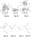
- Figs. 7a to 7d is the assembly process for connecting two angular, here perpendicular, furniture panels 21, 22 by means of the Figs. 5 and 6 shown tightening element 1.
- the tightening element 1 with the handle 11 folded up is inserted into the surface hole 23 of the first furniture panel 21 ( Fig. 7a ) until the second cover half 11 rests against the first furniture panel 21 ( Fig. 7b ).
- the tightening element 1 is then rotated in the surface bore 23 by e.g. 240° using the folded-up handle 11, i.e. without tools ( Fig. 7c ).
- the clamping bolt 2 enters the peripheral slot 6 and the bolt head 24, which is now gripped by the tightening contour 9, is drawn in further until the two furniture panels 21, 22 lie against each other without a gap.
- the handle 11 is folded down and locked in place to cover the surface bore 23 and the housing 3 ( Fig. 7d ).
Landscapes
- Engineering & Computer Science (AREA)
- General Engineering & Computer Science (AREA)
- Mechanical Engineering (AREA)
- Furniture Connections (AREA)
Description
- Die Erfindung betrifft ein Anzugselement zum werkzeuglosen Anziehen eines Spannbolzens gemäß dem Oberbegriff von Anspruch 1. Ein derartiges Anzugselement ist beispielsweise durch die
DE 296 05 547 U1 bekannt geworden. - Solche Anzugselemente und Verbindungsbeschläge sind hinlänglich bekannt und dienen dazu, zwei winkelig, vorzugweise rechtwinklig, aufeinanderstoßende Möbelteile miteinander zu befestigten. Bekannte Anzugselemente weisen einen Antrieb für einen Schraubendreher auf, um das in eine Flächenbohrung eines Möbelteils eingesetzte Anzugselement zu verdrehen und so die beiden Möbelteile spaltfrei miteinander zu verbinden.
- Aus
DE 296 05 547 U1 ist ein Beschlag zum lösbaren Verbinden von Bauteilen, insbesondere von plattenförmigen Bauteilen wie Möbelwänden, bekannt. Der Beschlag umfasst einen in einem Möbelteil verankerten Dübel, in dem ein zapfenartiges Verbindungsglied verankert ist, an dem ein im anderen Möbelteil achslos gelagerter Drehriegel mit einer Spannfläche angreift. Das Verbindungsglied besteht aus einem in den Dübel ragenden Spreizzapfen und einem daran um eine Achse kippbar gelagerten Verankerungsteil, an dem der Drehriegel angreift. - Ähnliche Beschläge sind auch aus
US 3 730 568 A undUS 3 456 969 A bekannt. Demgegenüber ist es die Aufgabe der Erfindung, ein Anzugselement der eingangs genannten Art weiter zu verbessern, insbesondere werkzeuglos verdrehen zu können. - Diese Aufgabe wird erfindungsgemäß durch ein Anzugselement mit den Merkmalen von Anspruch 1 gelöst.
- In der hochgeklappten Endstellung liegen die beiden Handhaben bevorzugt aneinander an und bilden so eine gemeinsame Handhabe. Die beiden Handhaben sind vorzugsweise jeweils als halbkreisförmige Deckelhälften ausgebildet, die in der heruntergeklappten Endstellung gemeinsam einen kreisförmigen Deckel ausbilden, welcher vorteilhafterweise die Stirnseite des Gehäuses vollständig abdeckt und radial nach außen über das Gehäuse vorsteht.
- Besonders bevorzugt sind die Handhaben in der heruntergeklappten Endstellung mit dem Gehäuse verrastet. In einer vorteilhaften Weiterbildung weist jede Handhabe einen Rastvorsprung auf, der in der heruntergeklappten Endstellung in einer Rastaufnahme des Gehäuses eingerastet ist, oder umgekehrt. In einer anderen vorteilhaften Weiterbildung weist jede Handhabe einen Haken auf, der in der heruntergeklappten Endstellung einen Hinterschnitt des Gehäuses rastend hintergreift, oder umgekehrt.
- Die Schwenkachse kann beispielsweise durch eine Zapfen/Loch-Rastverbindung zwischen der mindestens einen Handhabe und mindestens einem Lagerbock des Gehäuses oder durch eine Lagervorsprung/Lageraufnahme-Verbindung zwischen der klappbaren und der feststehenden Deckelhälfte gebildet sein.
- Vorzugweise weist das Gehäuse eine Umfangswand mit einem sich in Umfangsrichtung erstreckenden Umfangsschlitz auf, wobei die Innenseite der Umfangswand zu beiden Seiten des Umfangsschlitzes eine bezüglich der Mittelachse des Gehäuses exzentrische Anzugskontur aufweist.
- Die Erfindung betrifft außerdem einen Verbindungsbeschlag zum lösbaren Verbinden zweier winkelig, vorzugweise rechtwinklig, aufeinanderstoßender Möbelteile, mit einem an dem einen Möbelteil zu verankernden Spannbolzen und mit einem wie oben beschriebenen, in einer Flächenbohrung des anderen Möbelteils einzusetzenden Anzugselement.
- Die Erfindung betrifft schließlich auch eine Möbelanordnung mit zwei winkelig, vorzugweise rechtwinklig, aufeinanderstoßenden Möbelteilen, die mittels des Verbindungsbeschlags miteinander befestigt sind, wobei der Spannbolzen an einer Stirnseite des einen Möbelteils verankert ist und wobei das Anzugselement in eine Flächenbohrung des anderen Möbelteils eingesetzt ist und einen Bolzenkopf des Spannbolzens hintergreift. Durch eine Drehung des Anzugselements wird der Bolzenkopf des Spannbolzens gegriffen und angezogen und so die beiden Möbelteile spaltfrei aneinander befestigt. Nach dem Verdrehen des Anzugselementes wird die mindestens eine Handhabe heruntergeklappt und bevorzugt verrastet.
- Weitere Vorteile der Erfindung ergeben sich aus der Beschreibung, den Ansprüchen und der Zeichnung. Die gezeigten und beschriebenen Ausführungsformen sind nicht als abschließende Aufzählung zu verstehen, sondern haben vielmehr beispielhaften Charakter für die Schilderung der Erfindung.
- Es zeigen:
- Fign. 1a-1c
- ein erfindungsgemäßes Anzugselement mit zwei klappbaren (Dreh)Handhaben, wobei in
Fig. 1a beide Handhaben hochgeklappt, inFig. 1b die eine Handhabe hoch- und die andere Handhabe heruntergeklappt und inFig. 1c beide Handhaben heruntergeklappt sind; - Fig. 2
- die Einzelteile des erfindungsgemäßen Anzugselements;
- Fign. 3a, 3b
- eine Modifikation des erfindungsgemäßen Anzugselements in der hochgeklappten Endstellung (
Fig. 3a ) und in einer Detailansicht der Handhabe (Fig. 3b ); - Fign. 4a-4f
- den Montageablauf beim Verbinden zweier Möbelplatten mittels des in den
Fign. 1 bis 3 gezeigten Anzugselements; - Fign. 5a, 5b
- eine weitere Modifikation des erfindungsgemäßen Anzugselements mit einer einzigen klappbaren (Dreh)Handhabe, die in
Fig. 5a in der hochgeklappten und inFig. 5b in der heruntergekappten Endstellung gezeigt ist; - Fig. 6
- die Einzelteile des erfindungsgemäßen Anzugselements von
Fig. 5 ; und - Fign. 7a-7d
- den Montageablauf beim Verbinden zweier Möbelplatten mittels des in
Fig. 5 gezeigten Anzugselements. - Das in
Fign. 1a-1c gezeigte Anzugselement 1 dient zum werkzeuglosen Anziehen eines Spannbolzens 2 (Fign. 4c, 4e ). - Das Anzugselement 1 weist ein zylindrisches, topfförmiges Gehäuse 3 mit einer hier nach unten offenen Topföffnung 4 und mit einer Umfangswand 5 auf, in der sich in Umfangsrichtung ein Umfangsschlitz 6 erstreckt. An einem Schlitzende mündet der Umfangsschlitz 6 in eine nach unten hin offene Aussparung 7 der Umfangswand 5. Die Innenseite der Umfangswand 5 weist zu beiden Seiten des Umfangsschlitzes 6 eine bezüglich der Mittelachse 8 des Gehäuses 3 exzentrische Anzugskontur 9 auf.
- Auf der der Topföffnung 4 gegenüberliegenden Stirnseite 10 des Gehäuses 3 sind zwei plattenförmige (Dreh)Handhaben 11 um rechtwinklig zur Mittelachse 8 verlaufende, parallele Achsen 12 schwenkbar zwischen einer vom Gehäuse 3 abstehenden, hochgeklappten Endstellung (
Fig. 1a ) und einer an der Stirnseite 10 anliegenden, heruntergeklappten Endstellung (Fig. 1c ) gelagert. In der hochgeklappten Endstellung liegen die beiden Handhaben 11 aneinander an und bilden so eine gemeinsame Handhabe. Die beiden Handhaben 11 sind jeweils als halbkreisförmige Deckelhälften ausgebildet, die in der heruntergeklappten Endstellung gemeinsam einen kreisförmigen Deckel ausbilden, welcher die Stirnseite 10 des Gehäuses 3 vollständig abdeckt und radial nach außen über das Gehäuse 3 vorsteht. - Vorzugsweise sind das Gehäuse 3 aus Metall, z.B. Zinkdruckguß, und die Handhaben 11 aus Kunststoff gebildet.
- Wie in
Fig. 2 gezeigt, weist die Stirnseite 10 zwei Lagerböcke 13 mit jeweils beidseitigen Rastlöchern 14 auf, in denen die beiden Handhaben 11 mit Rastzapfen 15 eingerastet sind. Die Rastlöcher und -zapfen 14, 15 definieren auch die Schwenkachsen 12 der Handhaben 11. An den beiden Handhaben 11 ist unterseitig jeweils ein Rastvorsprung 18 angeformt, der in der heruntergeklappten Endstellung in eine Rastaufnahme 19 in der Stirnseite 10 eingerastet ist, um so die beiden Handhaben 11 in der heruntergeklappten Endstellung mit dem Gehäuse 3 zu verrasten. - Das Anzugselement 1 bildet zusammen mit dem Spannbolzen 2 einen in
Fig. 4c gezeigten Verbindungsbeschlag 20. - Vom Anzugselement der
Fign. 1 und 2 unterscheidet sich das inFign. 3a, 3b gezeigte Anzugselement 1 lediglich dadurch, dass hier die beiden Lagerböcke 13 jeweils einen Rastvorsprung 18 und die beiden Handhaben 11 jeweils zwei Rastaufnahmen 19 aufweisen. In der heruntergeklappten Endstellung sind die Rastvorsprünge 18 in die Rastaufnahmen 19 eingerastet, um so die beiden Handhaben 11 in der heruntergeklappten Endstellung mit dem Gehäuse 3 zu verrasten. - In den
Fign. 4a bis 4f ist der Montageablauf beim Verbinden zweier winkelig, hier rechtwinklig aufeinanderstoßender Möbelplatten 21, 22 mittels des Anzugselements 1 gezeigt. - In eine Flächenbohrung 23 der einen, ersten Möbelplatte 21 wird das Anzugelement 1 eingesetzt (
Fign. 4a, 4b ), wobei sich die beiden Handhaben 11 jeweils in der hochgeklappten Endstellung befinden. In der anderen Möbelplatte 22 ist der Spannbolzen 2 verankert, der sich mit seinem Bolzenkopf 24 durch eine Bohrung 25 in der Stirnseite der ersten Möbelplatte 21 und die offene Aussparung 7 des Anzugselements 1 hindurch bis in das Innere des Anzugselements 1 erstreckt (Fig. 4c ). Anschließend wird das Anzugselement 1 in der Flächenbohrung 23 mithilfe der beiden hochgeklappten Handhaben 11, also werkzeuglos, um z.B. 240° gedreht (Fig. 4d ). Dadurch tritt der Spannbolzen 2 in den Umfangsschlitz 6 ein und wird der nun von der Anzugskontur 9 hintergriffene Bolzenkopf 24 weiter eingezogen, bis die beiden Möbelplatten 21, 22 spaltfrei aneinander anliegen (Fig. 4e ). Abschließend werden die beiden Handhaben 11 heruntergeklappt und verrastet, um die Flächenbohrung 23 und das Gehäuse 3 abzudecken (Fig. 4f ). - Vom Anzugselement der
Fign. 1 und 2 unterscheidet sich das inFign. 5 und 6 gezeigte Anzugselement 1 durch eine einzige (Dreh)Handhabe 11 in Form einer halbkreisförmigen, ersten Deckelhälfte, die schwenkbar an einer halbkreisförmigen, zweiten Deckelhälfte 11' gelagert ist. Die zweite Deckelhälfte 11' ist stirnseitig am Gehäuse 3 feststehend angeformt und steht radial nach außen über das Gehäuse 3 vor. In der heruntergeklappten Endstellung bilden die beiden Deckelhälfte 11, 11' gemeinsam einen kreisförmigen Deckel aus, der radial nach außen über das Gehäuse 3 vorsteht. Die zweite Deckelhälfte 11' weist an ihrer Stirnseite eine halbzylinderförmige Lageraufnahme 27 auf, in der ein zylinderförmiger Lagervorsprung 28 der Handhabe 11 eingerastet und drehbar gelagert ist. Am Lagervorsprung 28 ist ein Ringbund 29 angeformt, der in eine Queraussparung 30 der Lageraufnahme 27 eingreift, um so den Lagervorsprung 28 in der Lageraufnahme 27 axial unverschiebbar festzulegen. An der Handhabe 11 ist unterseitig ein Haken 31 angeformt, der in der heruntergeklappten Endstellung einen Hinterschnitt 32 des Gehäuses 3 rastend hintergreift, um so die Handhabe 11 in der heruntergeklappten Endstellung mit dem Gehäuse 3 zu verrasten. - In den
Fign. 7a bis 7d ist der Montageablauf beim Verbinden zweier winkelig, hier rechtwinklig aufeinanderstoßender Möbelplatten 21, 22 mittels des inFign. 5 und 6 gezeigten Anzugselements 1 gezeigt. - In die Flächenbohrung 23 der einen, ersten Möbelplatte 21 wird das Anzugelement 1 mit hochgeklappter Handhabe 11 eingesetzt (
Fig. 7a ), bis die zweite Deckelhälfte 11 an der ersten Möbelplatte 21 anliegt (Fig. 7b ). Anschließend wird das Anzugselement 1 in der Flächenbohrung 23 mithilfe der hochgeklappten Handhabe 11, also werkzeuglos, um z.B. 240° gedreht (Fig. 7c ). Dadurch tritt der Spannbolzen 2 in den Umfangsschlitz 6 ein und wird der nun von der Anzugskontur 9 hintergriffene Bolzenkopf 24 weiter eingezogen, bis die beiden Möbelplatten 21, 22 spaltfrei aneinander anliegen. Abschließend wird die Handhabe 11 heruntergeklappt und verrastet, um die Flächenbohrung 23 und das Gehäuse 3 abzudecken (Fig. 7d ).
Claims (10)
- Anzugselement (1) zum werkzeuglosen Anziehen eines Spannbolzens (2), aufweisend ein zylindrisches, topfförmiges Gehäuse (3) mit einer Topföffnung (4), wobei auf der der Topföffnung (4) gegenüberliegenden Stirnseite (10) des Gehäuses (3) mindestens eine Handhabe (11) um eine rechtwinklig zur Mittelachse (8) des Gehäuses (3) verlaufende Achse (12) schwenkbar zwischen einer vom Gehäuse (3) abstehenden, hochgeklappten Stellung und einer an der Stirnseite (10) anliegenden, heruntergeklappten Endstellung gelagert ist,
dadurch gekennzeichnet,
dass auf der der Topföffnung (4) gegenüberliegenden Stirnseite (10) des Gehäuses (3) zwei Handhaben (11) um rechtwinklig zur Mittelachse (8) verlaufende Achsen (12) schwenkbar zwischen einer vom Gehäuse (3) abstehenden, hochgeklappten Stellung und einer an der Stirnseite (10) anliegenden, heruntergeklappten Endstellung gelagert sind. - Anzugselement nach Anspruch 1, dadurch gekennzeichnet, dass die beiden Handhaben (11) jeweils als insbesondere halbkreisförmige Deckelhälften ausgebildet sind, die in der heruntergeklappten Endstellung gemeinsam einen insbesondere kreisförmigen Deckel ausbilden.
- Anzugselement nach Anspruch 1 oder 2, dadurch gekennzeichnet, dass die beiden Handhaben (11) in der heruntergeklappten Endstellung radial nach außen über das Gehäuse (2) vorstehen.
- Anzugselement nach einem der vorhergehenden Ansprüche, dadurch gekennzeichnet, dass die Handhaben (11) in der heruntergeklappten Endstellung mit dem Gehäuse (3) verrastet sind.
- Anzugselement nach Anspruch 4, dadurch gekennzeichnet, dass jede Handhabe (11) einen Rastvorsprung (18) aufweist, der in der heruntergeklappten Endstellung in einer Rastaufnahme (19) des Gehäuses (3) eingerastet ist, oder umgekehrt.
- Anzugselement nach Anspruch 4, dadurch gekennzeichnet, dass jede Handhabe (11) einen Haken (31) aufweist, der in der heruntergeklappten Endstellung einen Hinterschnitt (32) des Gehäuses (2) rastend hintergreift, oder umgekehrt.
- Anzugselement nach einem der vorhergehenden Ansprüche, dadurch gekennzeichnet, dass die Schwenkachse (11) durch eine Zapfen/Loch-Rastverbindung (14, 15) zwischen der mindestens einen Handhabe (11) und mindestens einem Lagerbock (13) des Gehäuses (3) gebildet ist.
- Anzugselement nach einem der vorhergehenden Ansprüche, dadurch gekennzeichnet, dass das Gehäuses (3) eine Umfangswand (5) mit einem sich in Umfangsrichtung erstreckenden Umfangsschlitz (6) aufweist, wobei die Innenseite der Umfangswand (5) zu beiden Seiten des Umfangsschlitzes (6) eine bezüglich der Mittelachse (8) des Gehäuses (3) exzentrische Anzugskontur (9) aufweist.
- Verbindungsbeschlag (20) zum lösbaren Verbinden zweier winkelig, vorzugweise rechtwinklig, aufeinanderstoßender Möbelteile (21, 22), mit einem an dem einen Möbelteil (22) zu verankernden Spannbolzen (2) und mit einem in einer Flächenbohrung (23) des anderen Möbelteils (21) einzusetzenden Anzugselement (1) nach einem der vorhergehenden Ansprüche.
- Möbelanordnung mit zwei winkelig, vorzugweise rechtwinklig, aufeinanderstoßenden Möbelteilen (21, 22), die mittels des Verbindungsbeschlags (20) nach Anspruch 9 miteinander befestigt sind, wobei der Spannbolzen (2) an einer Stirnseite des einen Möbelteils (22) verankert ist und wobei das Anzugselement (1) in eine Flächenbohrung (23) des anderen Möbelteils (21) eingesetzt ist und einen Bolzenkopf (24) des Spannbolzens (2) hintergreift.
Applications Claiming Priority (2)
| Application Number | Priority Date | Filing Date | Title |
|---|---|---|---|
| DE202020102943.6U DE202020102943U1 (de) | 2020-05-22 | 2020-05-22 | Werkzeugloses Anzugselement und zugehöriger Verbindungsbeschlag |
| PCT/EP2021/061077 WO2021233652A1 (de) | 2020-05-22 | 2021-04-28 | Werkzeugloses anzugselement und zugehöriger verbindungsbeschlag |
Publications (2)
| Publication Number | Publication Date |
|---|---|
| EP4153874A1 EP4153874A1 (de) | 2023-03-29 |
| EP4153874B1 true EP4153874B1 (de) | 2024-06-12 |
Family
ID=71104483
Family Applications (1)
| Application Number | Title | Priority Date | Filing Date |
|---|---|---|---|
| EP21722813.9A Active EP4153874B1 (de) | 2020-05-22 | 2021-04-28 | Werkzeugloses anzugselement und zugehöriger verbindungsbeschlag |
Country Status (4)
| Country | Link |
|---|---|
| US (1) | US20230151838A1 (de) |
| EP (1) | EP4153874B1 (de) |
| DE (1) | DE202020102943U1 (de) |
| WO (1) | WO2021233652A1 (de) |
Families Citing this family (3)
| Publication number | Priority date | Publication date | Assignee | Title |
|---|---|---|---|---|
| WO2025262726A1 (en) | 2024-06-20 | 2025-12-26 | Adimo S.R.L. | Connection device for parts of a furnishing element |
| KR102862718B1 (ko) * | 2024-11-19 | 2025-09-23 | 주식회사 퍼맥스 | 미니픽스용 하우징 |
| KR102862722B1 (ko) * | 2024-12-11 | 2025-09-23 | 주식회사 퍼맥스 | 미니픽스용 하우징 |
Family Cites Families (18)
| Publication number | Priority date | Publication date | Assignee | Title |
|---|---|---|---|---|
| FR508660A (fr) * | 1919-12-20 | 1920-10-20 | Ernest Gillen | Dispositif de démontage et remontage instantané de tous meubles |
| DE1963566U (de) * | 1967-01-17 | 1967-07-06 | Christian Holzaepfel K G Moebe | Vorrichtung zum gegenseitigen verspannen von aufeinander senkrecht stehenden moebelwaenden. |
| ES165887Y (es) * | 1970-03-16 | 1971-12-01 | Giovannetti | Dispositivo de union permanente de elementos de cualquier material con fuerte posibilidad de desunion. |
| US3730568A (en) * | 1971-03-15 | 1973-05-01 | F Giovannetti | Connector |
| AT376770B (de) * | 1978-07-28 | 1984-12-27 | Heinze Richard Gmbh Co Kg | Moebelbeschlagteil |
| FR2445461A3 (fr) * | 1978-12-26 | 1980-07-25 | Spinelli Giuseppe | Dispositif de jonction pour assemblage de panneaux employes pour la realisation de meubles |
| DE29511216U1 (de) * | 1995-07-11 | 1995-09-14 | Arturo Salice S.P.A., Novedrate, Como | Befestigungselement |
| AT596U1 (de) * | 1995-05-02 | 1996-01-25 | Blum Gmbh Julius | Beschlag zum lösbaren verbinden von bauteilen |
| AT407777B (de) * | 1999-04-26 | 2001-06-25 | Blum Gmbh Julius | Verbindungsbeschlag zum lösbaren verbinden zweier möbelteile |
| ITMI20080229A1 (it) * | 2008-02-13 | 2009-08-14 | Agostino Ferrari Spa | "ala di cerniera per mobilio a montaggio rapido" |
| FR2927677B3 (fr) * | 2008-02-19 | 2010-03-12 | Kenmark Ind Co Ltd | Module d'assemblage verrouille |
| US20100202852A1 (en) * | 2009-02-09 | 2010-08-12 | Krause Steven T | No-tools panel coupler and insert |
| CN201448322U (zh) * | 2009-05-12 | 2010-05-05 | 曹蕾 | 一种家具连接拨扣 |
| CN202391885U (zh) * | 2011-12-01 | 2012-08-22 | 福建惠乐家商贸有限公司 | 一种家具连接扣件 |
| CN102954082A (zh) * | 2012-05-26 | 2013-03-06 | 上海昊纬信息科技有限公司 | 一种翻盖式锁扣 |
| US20150147115A1 (en) * | 2013-11-28 | 2015-05-28 | Ya Yun Yang | Hidden fastening device for boards |
| CN206129804U (zh) * | 2016-09-27 | 2017-04-26 | (香港)立而翔木业有限公司东莞代表处 | 一种连接件 |
| DE202019106844U1 (de) * | 2019-12-09 | 2020-01-20 | Häfele Berlin Gmbh & Co Kg | Anzugelement |
-
2020
- 2020-05-22 DE DE202020102943.6U patent/DE202020102943U1/de active Active
-
2021
- 2021-04-28 EP EP21722813.9A patent/EP4153874B1/de active Active
- 2021-04-28 WO PCT/EP2021/061077 patent/WO2021233652A1/de not_active Ceased
-
2022
- 2022-11-18 US US18/056,872 patent/US20230151838A1/en not_active Abandoned
Also Published As
| Publication number | Publication date |
|---|---|
| WO2021233652A1 (de) | 2021-11-25 |
| US20230151838A1 (en) | 2023-05-18 |
| EP4153874A1 (de) | 2023-03-29 |
| DE202020102943U1 (de) | 2020-05-29 |
Similar Documents
| Publication | Publication Date | Title |
|---|---|---|
| EP0362883B1 (de) | Kofferscharnier | |
| EP3572605B1 (de) | Schaltschrankgehäuse mit einem über eine scharnieranordnung befestigten türelement | |
| EP2778492B1 (de) | Verbindung zweier Adapterteile einer modular aufbaubaren Tragvorrichtung | |
| EP4013969B1 (de) | Anzugelement | |
| EP4153874A1 (de) | Werkzeugloses anzugselement und zugehöriger verbindungsbeschlag | |
| EP0597805B1 (de) | Rohrschelle | |
| DE3236719C2 (de) | Klemmverbinder für Profilleisten | |
| EP1340574B1 (de) | Handfräsmaschine | |
| EP0898089B1 (de) | Einteiliger Beschlag | |
| DE29722488U1 (de) | Vorreiberverschluß für dickwandige Türen, Klappen o.dgl. | |
| DE202009013177U1 (de) | Verbindungselement | |
| EP3867467A2 (de) | Drückerlagerung, tür- oder fensterdrücker mit einer drückerlagerung | |
| EP0698710A1 (de) | Band für Türen, Fenster und dergleichen | |
| DE10133708C1 (de) | Befestigungssystem für eine geteilte Kraftfahrzeug-Fondlehne | |
| DE2905378A1 (de) | Moebelbeschlagteil | |
| DE19522961C2 (de) | Heckklappenscharnier mit einem zusätzlichen Drehgelenk | |
| EP3933217A1 (de) | Werkzeugloser frontanbindungsbeschlag | |
| DE202007014470U1 (de) | Schleifrad für eine spanabhebende Bearbeitung von Gegenständen, insbesondere von Steinen, Ziegeln o.dgl., oder Radkörper oder Schleifring oder Verschluss-Stück für ein solches Schleifrad | |
| DE19623084C1 (de) | Nachrüstbares Scharnier | |
| EP3808927A1 (de) | Anordnung mit einem rahmen und einem mit hilfe von bändern an dem rahmen angebrachten flügel | |
| DE4440553C1 (de) | Anordnung zur Verbindung von zwei Elementen von Möbeln | |
| DE202007016708U1 (de) | Band für Türen, Fenster o.dgl. | |
| DE19703880C2 (de) | Verriegelungsvorrichtung | |
| DE20107525U1 (de) | Vorrichtung zur Befestigung eines Beschlagteils | |
| DE202004002082U1 (de) | Rohrbogen |
Legal Events
| Date | Code | Title | Description |
|---|---|---|---|
| STAA | Information on the status of an ep patent application or granted ep patent |
Free format text: STATUS: UNKNOWN |
|
| STAA | Information on the status of an ep patent application or granted ep patent |
Free format text: STATUS: THE INTERNATIONAL PUBLICATION HAS BEEN MADE |
|
| PUAI | Public reference made under article 153(3) epc to a published international application that has entered the european phase |
Free format text: ORIGINAL CODE: 0009012 |
|
| STAA | Information on the status of an ep patent application or granted ep patent |
Free format text: STATUS: REQUEST FOR EXAMINATION WAS MADE |
|
| 17P | Request for examination filed |
Effective date: 20221222 |
|
| AK | Designated contracting states |
Kind code of ref document: A1 Designated state(s): AL AT BE BG CH CY CZ DE DK EE ES FI FR GB GR HR HU IE IS IT LI LT LU LV MC MK MT NL NO PL PT RO RS SE SI SK SM TR |
|
| P01 | Opt-out of the competence of the unified patent court (upc) registered |
Effective date: 20230630 |
|
| DAV | Request for validation of the european patent (deleted) | ||
| DAX | Request for extension of the european patent (deleted) | ||
| GRAP | Despatch of communication of intention to grant a patent |
Free format text: ORIGINAL CODE: EPIDOSNIGR1 |
|
| STAA | Information on the status of an ep patent application or granted ep patent |
Free format text: STATUS: GRANT OF PATENT IS INTENDED |
|
| INTG | Intention to grant announced |
Effective date: 20240125 |
|
| GRAS | Grant fee paid |
Free format text: ORIGINAL CODE: EPIDOSNIGR3 |
|
| GRAA | (expected) grant |
Free format text: ORIGINAL CODE: 0009210 |
|
| STAA | Information on the status of an ep patent application or granted ep patent |
Free format text: STATUS: THE PATENT HAS BEEN GRANTED |
|
| AK | Designated contracting states |
Kind code of ref document: B1 Designated state(s): AL AT BE BG CH CY CZ DE DK EE ES FI FR GB GR HR HU IE IS IT LI LT LU LV MC MK MT NL NO PL PT RO RS SE SI SK SM TR |
|
| REG | Reference to a national code |
Ref country code: GB Ref legal event code: FG4D Free format text: NOT ENGLISH |
|
| REG | Reference to a national code |
Ref country code: CH Ref legal event code: EP |
|
| REG | Reference to a national code |
Ref country code: DE Ref legal event code: R096 Ref document number: 502021003993 Country of ref document: DE |
|
| REG | Reference to a national code |
Ref country code: IE Ref legal event code: FG4D Free format text: LANGUAGE OF EP DOCUMENT: GERMAN |
|
| PG25 | Lapsed in a contracting state [announced via postgrant information from national office to epo] |
Ref country code: BG Free format text: LAPSE BECAUSE OF FAILURE TO SUBMIT A TRANSLATION OF THE DESCRIPTION OR TO PAY THE FEE WITHIN THE PRESCRIBED TIME-LIMIT Effective date: 20240612 |
|
| PG25 | Lapsed in a contracting state [announced via postgrant information from national office to epo] |
Ref country code: FI Free format text: LAPSE BECAUSE OF FAILURE TO SUBMIT A TRANSLATION OF THE DESCRIPTION OR TO PAY THE FEE WITHIN THE PRESCRIBED TIME-LIMIT Effective date: 20240612 Ref country code: HR Free format text: LAPSE BECAUSE OF FAILURE TO SUBMIT A TRANSLATION OF THE DESCRIPTION OR TO PAY THE FEE WITHIN THE PRESCRIBED TIME-LIMIT Effective date: 20240612 |
|
| REG | Reference to a national code |
Ref country code: LT Ref legal event code: MG9D |
|
| PG25 | Lapsed in a contracting state [announced via postgrant information from national office to epo] |
Ref country code: GR Free format text: LAPSE BECAUSE OF FAILURE TO SUBMIT A TRANSLATION OF THE DESCRIPTION OR TO PAY THE FEE WITHIN THE PRESCRIBED TIME-LIMIT Effective date: 20240913 |
|
| REG | Reference to a national code |
Ref country code: NL Ref legal event code: MP Effective date: 20240612 |
|
| PG25 | Lapsed in a contracting state [announced via postgrant information from national office to epo] |
Ref country code: ES Free format text: LAPSE BECAUSE OF FAILURE TO SUBMIT A TRANSLATION OF THE DESCRIPTION OR TO PAY THE FEE WITHIN THE PRESCRIBED TIME-LIMIT Effective date: 20240612 |
|
| PG25 | Lapsed in a contracting state [announced via postgrant information from national office to epo] |
Ref country code: LV Free format text: LAPSE BECAUSE OF FAILURE TO SUBMIT A TRANSLATION OF THE DESCRIPTION OR TO PAY THE FEE WITHIN THE PRESCRIBED TIME-LIMIT Effective date: 20240612 |
|
| PG25 | Lapsed in a contracting state [announced via postgrant information from national office to epo] |
Ref country code: NO Free format text: LAPSE BECAUSE OF FAILURE TO SUBMIT A TRANSLATION OF THE DESCRIPTION OR TO PAY THE FEE WITHIN THE PRESCRIBED TIME-LIMIT Effective date: 20240912 Ref country code: LV Free format text: LAPSE BECAUSE OF FAILURE TO SUBMIT A TRANSLATION OF THE DESCRIPTION OR TO PAY THE FEE WITHIN THE PRESCRIBED TIME-LIMIT Effective date: 20240612 Ref country code: HR Free format text: LAPSE BECAUSE OF FAILURE TO SUBMIT A TRANSLATION OF THE DESCRIPTION OR TO PAY THE FEE WITHIN THE PRESCRIBED TIME-LIMIT Effective date: 20240612 Ref country code: GR Free format text: LAPSE BECAUSE OF FAILURE TO SUBMIT A TRANSLATION OF THE DESCRIPTION OR TO PAY THE FEE WITHIN THE PRESCRIBED TIME-LIMIT Effective date: 20240913 Ref country code: FI Free format text: LAPSE BECAUSE OF FAILURE TO SUBMIT A TRANSLATION OF THE DESCRIPTION OR TO PAY THE FEE WITHIN THE PRESCRIBED TIME-LIMIT Effective date: 20240612 Ref country code: ES Free format text: LAPSE BECAUSE OF FAILURE TO SUBMIT A TRANSLATION OF THE DESCRIPTION OR TO PAY THE FEE WITHIN THE PRESCRIBED TIME-LIMIT Effective date: 20240612 Ref country code: BG Free format text: LAPSE BECAUSE OF FAILURE TO SUBMIT A TRANSLATION OF THE DESCRIPTION OR TO PAY THE FEE WITHIN THE PRESCRIBED TIME-LIMIT Effective date: 20240612 Ref country code: RS Free format text: LAPSE BECAUSE OF FAILURE TO SUBMIT A TRANSLATION OF THE DESCRIPTION OR TO PAY THE FEE WITHIN THE PRESCRIBED TIME-LIMIT Effective date: 20240912 |
|
| PG25 | Lapsed in a contracting state [announced via postgrant information from national office to epo] |
Ref country code: NL Free format text: LAPSE BECAUSE OF FAILURE TO SUBMIT A TRANSLATION OF THE DESCRIPTION OR TO PAY THE FEE WITHIN THE PRESCRIBED TIME-LIMIT Effective date: 20240612 |
|
| PG25 | Lapsed in a contracting state [announced via postgrant information from national office to epo] |
Ref country code: NL Free format text: LAPSE BECAUSE OF FAILURE TO SUBMIT A TRANSLATION OF THE DESCRIPTION OR TO PAY THE FEE WITHIN THE PRESCRIBED TIME-LIMIT Effective date: 20240612 |
|
| PG25 | Lapsed in a contracting state [announced via postgrant information from national office to epo] |
Ref country code: PT Free format text: LAPSE BECAUSE OF FAILURE TO SUBMIT A TRANSLATION OF THE DESCRIPTION OR TO PAY THE FEE WITHIN THE PRESCRIBED TIME-LIMIT Effective date: 20241014 |
|
| PG25 | Lapsed in a contracting state [announced via postgrant information from national office to epo] |
Ref country code: PT Free format text: LAPSE BECAUSE OF FAILURE TO SUBMIT A TRANSLATION OF THE DESCRIPTION OR TO PAY THE FEE WITHIN THE PRESCRIBED TIME-LIMIT Effective date: 20241014 |
|
| PG25 | Lapsed in a contracting state [announced via postgrant information from national office to epo] |
Ref country code: PL Free format text: LAPSE BECAUSE OF FAILURE TO SUBMIT A TRANSLATION OF THE DESCRIPTION OR TO PAY THE FEE WITHIN THE PRESCRIBED TIME-LIMIT Effective date: 20240612 |
|
| PG25 | Lapsed in a contracting state [announced via postgrant information from national office to epo] |
Ref country code: EE Free format text: LAPSE BECAUSE OF FAILURE TO SUBMIT A TRANSLATION OF THE DESCRIPTION OR TO PAY THE FEE WITHIN THE PRESCRIBED TIME-LIMIT Effective date: 20240612 |
|
| PG25 | Lapsed in a contracting state [announced via postgrant information from national office to epo] |
Ref country code: IS Free format text: LAPSE BECAUSE OF FAILURE TO SUBMIT A TRANSLATION OF THE DESCRIPTION OR TO PAY THE FEE WITHIN THE PRESCRIBED TIME-LIMIT Effective date: 20241012 |
|
| PG25 | Lapsed in a contracting state [announced via postgrant information from national office to epo] |
Ref country code: CZ Free format text: LAPSE BECAUSE OF FAILURE TO SUBMIT A TRANSLATION OF THE DESCRIPTION OR TO PAY THE FEE WITHIN THE PRESCRIBED TIME-LIMIT Effective date: 20240612 |
|
| PG25 | Lapsed in a contracting state [announced via postgrant information from national office to epo] |
Ref country code: SK Free format text: LAPSE BECAUSE OF FAILURE TO SUBMIT A TRANSLATION OF THE DESCRIPTION OR TO PAY THE FEE WITHIN THE PRESCRIBED TIME-LIMIT Effective date: 20240612 Ref country code: RO Free format text: LAPSE BECAUSE OF FAILURE TO SUBMIT A TRANSLATION OF THE DESCRIPTION OR TO PAY THE FEE WITHIN THE PRESCRIBED TIME-LIMIT Effective date: 20240612 |
|
| PG25 | Lapsed in a contracting state [announced via postgrant information from national office to epo] |
Ref country code: SM Free format text: LAPSE BECAUSE OF FAILURE TO SUBMIT A TRANSLATION OF THE DESCRIPTION OR TO PAY THE FEE WITHIN THE PRESCRIBED TIME-LIMIT Effective date: 20240612 |
|
| PG25 | Lapsed in a contracting state [announced via postgrant information from national office to epo] |
Ref country code: SM Free format text: LAPSE BECAUSE OF FAILURE TO SUBMIT A TRANSLATION OF THE DESCRIPTION OR TO PAY THE FEE WITHIN THE PRESCRIBED TIME-LIMIT Effective date: 20240612 Ref country code: SK Free format text: LAPSE BECAUSE OF FAILURE TO SUBMIT A TRANSLATION OF THE DESCRIPTION OR TO PAY THE FEE WITHIN THE PRESCRIBED TIME-LIMIT Effective date: 20240612 Ref country code: RO Free format text: LAPSE BECAUSE OF FAILURE TO SUBMIT A TRANSLATION OF THE DESCRIPTION OR TO PAY THE FEE WITHIN THE PRESCRIBED TIME-LIMIT Effective date: 20240612 Ref country code: PL Free format text: LAPSE BECAUSE OF FAILURE TO SUBMIT A TRANSLATION OF THE DESCRIPTION OR TO PAY THE FEE WITHIN THE PRESCRIBED TIME-LIMIT Effective date: 20240612 Ref country code: IS Free format text: LAPSE BECAUSE OF FAILURE TO SUBMIT A TRANSLATION OF THE DESCRIPTION OR TO PAY THE FEE WITHIN THE PRESCRIBED TIME-LIMIT Effective date: 20241012 Ref country code: EE Free format text: LAPSE BECAUSE OF FAILURE TO SUBMIT A TRANSLATION OF THE DESCRIPTION OR TO PAY THE FEE WITHIN THE PRESCRIBED TIME-LIMIT Effective date: 20240612 Ref country code: CZ Free format text: LAPSE BECAUSE OF FAILURE TO SUBMIT A TRANSLATION OF THE DESCRIPTION OR TO PAY THE FEE WITHIN THE PRESCRIBED TIME-LIMIT Effective date: 20240612 |
|
| PG25 | Lapsed in a contracting state [announced via postgrant information from national office to epo] |
Ref country code: IT Free format text: LAPSE BECAUSE OF FAILURE TO SUBMIT A TRANSLATION OF THE DESCRIPTION OR TO PAY THE FEE WITHIN THE PRESCRIBED TIME-LIMIT Effective date: 20240612 |
|
| REG | Reference to a national code |
Ref country code: DE Ref legal event code: R097 Ref document number: 502021003993 Country of ref document: DE |
|
| PG25 | Lapsed in a contracting state [announced via postgrant information from national office to epo] |
Ref country code: DK Free format text: LAPSE BECAUSE OF FAILURE TO SUBMIT A TRANSLATION OF THE DESCRIPTION OR TO PAY THE FEE WITHIN THE PRESCRIBED TIME-LIMIT Effective date: 20240612 |
|
| PLBE | No opposition filed within time limit |
Free format text: ORIGINAL CODE: 0009261 |
|
| STAA | Information on the status of an ep patent application or granted ep patent |
Free format text: STATUS: NO OPPOSITION FILED WITHIN TIME LIMIT |
|
| 26N | No opposition filed |
Effective date: 20250313 |
|
| PGFP | Annual fee paid to national office [announced via postgrant information from national office to epo] |
Ref country code: DE Payment date: 20250424 Year of fee payment: 5 |
|
| PGFP | Annual fee paid to national office [announced via postgrant information from national office to epo] |
Ref country code: AT Payment date: 20250721 Year of fee payment: 5 |
|
| PG25 | Lapsed in a contracting state [announced via postgrant information from national office to epo] |
Ref country code: SE Free format text: LAPSE BECAUSE OF FAILURE TO SUBMIT A TRANSLATION OF THE DESCRIPTION OR TO PAY THE FEE WITHIN THE PRESCRIBED TIME-LIMIT Effective date: 20240612 |
|
| REG | Reference to a national code |
Ref country code: CH Ref legal event code: H13 Free format text: ST27 STATUS EVENT CODE: U-0-0-H10-H13 (AS PROVIDED BY THE NATIONAL OFFICE) Effective date: 20251125 |
|
| PG25 | Lapsed in a contracting state [announced via postgrant information from national office to epo] |
Ref country code: LU Free format text: LAPSE BECAUSE OF NON-PAYMENT OF DUE FEES Effective date: 20250428 |
|
| PG25 | Lapsed in a contracting state [announced via postgrant information from national office to epo] |
Ref country code: MC Free format text: LAPSE BECAUSE OF FAILURE TO SUBMIT A TRANSLATION OF THE DESCRIPTION OR TO PAY THE FEE WITHIN THE PRESCRIBED TIME-LIMIT Effective date: 20240612 |
|
| GBPC | Gb: european patent ceased through non-payment of renewal fee |
Effective date: 20250428 |
|
| REG | Reference to a national code |
Ref country code: BE Ref legal event code: MM Effective date: 20250430 |
|
| PG25 | Lapsed in a contracting state [announced via postgrant information from national office to epo] |
Ref country code: GB Free format text: LAPSE BECAUSE OF NON-PAYMENT OF DUE FEES Effective date: 20250428 |
|
| PG25 | Lapsed in a contracting state [announced via postgrant information from national office to epo] |
Ref country code: FR Free format text: LAPSE BECAUSE OF NON-PAYMENT OF DUE FEES Effective date: 20250430 |
|
| PG25 | Lapsed in a contracting state [announced via postgrant information from national office to epo] |
Ref country code: BE Free format text: LAPSE BECAUSE OF NON-PAYMENT OF DUE FEES Effective date: 20250430 |
|
| PG25 | Lapsed in a contracting state [announced via postgrant information from national office to epo] |
Ref country code: CH Free format text: LAPSE BECAUSE OF NON-PAYMENT OF DUE FEES Effective date: 20250430 |
|
| PG25 | Lapsed in a contracting state [announced via postgrant information from national office to epo] |
Ref country code: IE Free format text: LAPSE BECAUSE OF NON-PAYMENT OF DUE FEES Effective date: 20250428 |