EP4152489A1 - Knopfzelle und herstellungsverfahren dafür sowie elektronische vorrichtung - Google Patents
Knopfzelle und herstellungsverfahren dafür sowie elektronische vorrichtung Download PDFInfo
- Publication number
- EP4152489A1 EP4152489A1 EP21818153.5A EP21818153A EP4152489A1 EP 4152489 A1 EP4152489 A1 EP 4152489A1 EP 21818153 A EP21818153 A EP 21818153A EP 4152489 A1 EP4152489 A1 EP 4152489A1
- Authority
- EP
- European Patent Office
- Prior art keywords
- conductive member
- housing
- button cell
- head cover
- tab
- Prior art date
- Legal status (The legal status is an assumption and is not a legal conclusion. Google has not performed a legal analysis and makes no representation as to the accuracy of the status listed.)
- Pending
Links
Images






Classifications
-
- H—ELECTRICITY
- H01—ELECTRIC ELEMENTS
- H01M—PROCESSES OR MEANS, e.g. BATTERIES, FOR THE DIRECT CONVERSION OF CHEMICAL ENERGY INTO ELECTRICAL ENERGY
- H01M50/00—Constructional details or processes of manufacture of the non-active parts of electrochemical cells other than fuel cells, e.g. hybrid cells
- H01M50/60—Arrangements or processes for filling or topping-up with liquids; Arrangements or processes for draining liquids from casings
- H01M50/609—Arrangements or processes for filling with liquid, e.g. electrolytes
- H01M50/627—Filling ports
- H01M50/636—Closing or sealing filling ports, e.g. using lids
-
- H—ELECTRICITY
- H01—ELECTRIC ELEMENTS
- H01M—PROCESSES OR MEANS, e.g. BATTERIES, FOR THE DIRECT CONVERSION OF CHEMICAL ENERGY INTO ELECTRICAL ENERGY
- H01M50/00—Constructional details or processes of manufacture of the non-active parts of electrochemical cells other than fuel cells, e.g. hybrid cells
- H01M50/10—Primary casings; Jackets or wrappings
- H01M50/102—Primary casings; Jackets or wrappings characterised by their shape or physical structure
- H01M50/109—Primary casings; Jackets or wrappings characterised by their shape or physical structure of button or coin shape
-
- H—ELECTRICITY
- H01—ELECTRIC ELEMENTS
- H01M—PROCESSES OR MEANS, e.g. BATTERIES, FOR THE DIRECT CONVERSION OF CHEMICAL ENERGY INTO ELECTRICAL ENERGY
- H01M50/00—Constructional details or processes of manufacture of the non-active parts of electrochemical cells other than fuel cells, e.g. hybrid cells
- H01M50/10—Primary casings; Jackets or wrappings
- H01M50/147—Lids or covers
- H01M50/148—Lids or covers characterised by their shape
- H01M50/153—Lids or covers characterised by their shape for button or coin cells
-
- H—ELECTRICITY
- H01—ELECTRIC ELEMENTS
- H01M—PROCESSES OR MEANS, e.g. BATTERIES, FOR THE DIRECT CONVERSION OF CHEMICAL ENERGY INTO ELECTRICAL ENERGY
- H01M50/00—Constructional details or processes of manufacture of the non-active parts of electrochemical cells other than fuel cells, e.g. hybrid cells
- H01M50/10—Primary casings; Jackets or wrappings
- H01M50/147—Lids or covers
- H01M50/166—Lids or covers characterised by the methods of assembling casings with lids
- H01M50/169—Lids or covers characterised by the methods of assembling casings with lids by welding, brazing or soldering
-
- H—ELECTRICITY
- H01—ELECTRIC ELEMENTS
- H01M—PROCESSES OR MEANS, e.g. BATTERIES, FOR THE DIRECT CONVERSION OF CHEMICAL ENERGY INTO ELECTRICAL ENERGY
- H01M50/00—Constructional details or processes of manufacture of the non-active parts of electrochemical cells other than fuel cells, e.g. hybrid cells
- H01M50/10—Primary casings; Jackets or wrappings
- H01M50/183—Sealing members
- H01M50/184—Sealing members characterised by their shape or structure
-
- H—ELECTRICITY
- H01—ELECTRIC ELEMENTS
- H01M—PROCESSES OR MEANS, e.g. BATTERIES, FOR THE DIRECT CONVERSION OF CHEMICAL ENERGY INTO ELECTRICAL ENERGY
- H01M50/00—Constructional details or processes of manufacture of the non-active parts of electrochemical cells other than fuel cells, e.g. hybrid cells
- H01M50/50—Current conducting connections for cells or batteries
- H01M50/531—Electrode connections inside a battery casing
- H01M50/536—Electrode connections inside a battery casing characterised by the method of fixing the leads to the electrodes, e.g. by welding
-
- H—ELECTRICITY
- H01—ELECTRIC ELEMENTS
- H01M—PROCESSES OR MEANS, e.g. BATTERIES, FOR THE DIRECT CONVERSION OF CHEMICAL ENERGY INTO ELECTRICAL ENERGY
- H01M50/00—Constructional details or processes of manufacture of the non-active parts of electrochemical cells other than fuel cells, e.g. hybrid cells
- H01M50/50—Current conducting connections for cells or batteries
- H01M50/531—Electrode connections inside a battery casing
- H01M50/538—Connection of several leads or tabs of wound or folded electrode stacks
-
- H—ELECTRICITY
- H01—ELECTRIC ELEMENTS
- H01M—PROCESSES OR MEANS, e.g. BATTERIES, FOR THE DIRECT CONVERSION OF CHEMICAL ENERGY INTO ELECTRICAL ENERGY
- H01M50/00—Constructional details or processes of manufacture of the non-active parts of electrochemical cells other than fuel cells, e.g. hybrid cells
- H01M50/50—Current conducting connections for cells or batteries
- H01M50/543—Terminals
- H01M50/552—Terminals characterised by their shape
- H01M50/553—Terminals adapted for prismatic, pouch or rectangular cells
- H01M50/555—Window-shaped terminals
-
- H—ELECTRICITY
- H01—ELECTRIC ELEMENTS
- H01M—PROCESSES OR MEANS, e.g. BATTERIES, FOR THE DIRECT CONVERSION OF CHEMICAL ENERGY INTO ELECTRICAL ENERGY
- H01M50/00—Constructional details or processes of manufacture of the non-active parts of electrochemical cells other than fuel cells, e.g. hybrid cells
- H01M50/50—Current conducting connections for cells or batteries
- H01M50/543—Terminals
- H01M50/564—Terminals characterised by their manufacturing process
- H01M50/566—Terminals characterised by their manufacturing process by welding, soldering or brazing
-
- H—ELECTRICITY
- H01—ELECTRIC ELEMENTS
- H01M—PROCESSES OR MEANS, e.g. BATTERIES, FOR THE DIRECT CONVERSION OF CHEMICAL ENERGY INTO ELECTRICAL ENERGY
- H01M50/00—Constructional details or processes of manufacture of the non-active parts of electrochemical cells other than fuel cells, e.g. hybrid cells
- H01M50/60—Arrangements or processes for filling or topping-up with liquids; Arrangements or processes for draining liquids from casings
- H01M50/609—Arrangements or processes for filling with liquid, e.g. electrolytes
- H01M50/627—Filling ports
-
- Y—GENERAL TAGGING OF NEW TECHNOLOGICAL DEVELOPMENTS; GENERAL TAGGING OF CROSS-SECTIONAL TECHNOLOGIES SPANNING OVER SEVERAL SECTIONS OF THE IPC; TECHNICAL SUBJECTS COVERED BY FORMER USPC CROSS-REFERENCE ART COLLECTIONS [XRACs] AND DIGESTS
- Y02—TECHNOLOGIES OR APPLICATIONS FOR MITIGATION OR ADAPTATION AGAINST CLIMATE CHANGE
- Y02E—REDUCTION OF GREENHOUSE GAS [GHG] EMISSIONS, RELATED TO ENERGY GENERATION, TRANSMISSION OR DISTRIBUTION
- Y02E60/00—Enabling technologies; Technologies with a potential or indirect contribution to GHG emissions mitigation
- Y02E60/10—Energy storage using batteries
-
- Y—GENERAL TAGGING OF NEW TECHNOLOGICAL DEVELOPMENTS; GENERAL TAGGING OF CROSS-SECTIONAL TECHNOLOGIES SPANNING OVER SEVERAL SECTIONS OF THE IPC; TECHNICAL SUBJECTS COVERED BY FORMER USPC CROSS-REFERENCE ART COLLECTIONS [XRACs] AND DIGESTS
- Y02—TECHNOLOGIES OR APPLICATIONS FOR MITIGATION OR ADAPTATION AGAINST CLIMATE CHANGE
- Y02P—CLIMATE CHANGE MITIGATION TECHNOLOGIES IN THE PRODUCTION OR PROCESSING OF GOODS
- Y02P70/00—Climate change mitigation technologies in the production process for final industrial or consumer products
- Y02P70/50—Manufacturing or production processes characterised by the final manufactured product
Definitions
- the present application relates to the technical field of cell, in particular relates to a button cell and manufacturing method thereof and electronic equipment.
- Button cell refers to a cell with a boundary dimension like a button. Generally speaking, its diameter is larger and its thickness is thinner. Because of its small size, button cell has been widely used in various microelectronic equipment, such as wearable electronic equipment field, medical products field and the like.
- the sealing performance is extremely important for the button cell.
- the sealing performance of the button cell in the prior art is poor, resulting in poor safety and stability of the button cell.
- the embodiment of the present application provides a button cell and manufacturing method thereof and electronic equipment, having better safety and stability.
- a first aspect of the embodiment of the present application provides a button cell, including a housing, an electrode assembly and a covering member.
- An accommodating cavity is disposed in the housing, the electrode assembly is located in the accommodating cavity, and the housing is provided with a liquid injection hole for injecting electrolyte into the accommodating cavity;
- an outer surface of the housing is provided with a recessed portion, which is recessed towards an inner side of the accommodating cavity, and the recessed portion is located at an orifice of the liquid injection hole and communicated with the liquid injection hole;
- the covering member is welded to an outer side of the housing to cover the recessed portion and the liquid injection hole.
- a second aspect of the embodiment of the present application provides an electronic equipment, including an electronic equipment body and a button cell in the first aspect, the button cell providing electric energy for the electronic equipment body.
- a third aspect of the embodiment of the present application provides a button cell, which includes: includes: a housing, an electric core and a conductive member; the housing includes a bottom housing and a head cover, the head cover and the bottom housing are hermetically connected, an accommodating cavity for holding the electric core is formed by enclosing of the bottom housing and the head cover, the head cover is provided with a through hole communicated with the accommodating cavity, and the conductive member covers the through hole and is connected with the head cover in an insulated and sealed manner through a sealing rubber ring; the conductive member is also provided with a liquid injection port for injecting electrolyte into the accommodating cavity, the liquid injection port is covered with a covering member, the covering member and the liquid injection port are hermetically connected; the electric core has a first tab and a second tab, the first tab is butted to and welded with an inner bottom wall of the bottom housing, and the second tab is electrically connected with the conductive member.
- a fourth aspect of the embodiment of the present application provides an electronic equipment, including an electronic equipment body and a button cell provided by the third aspect, the button cell providing electric energy for the electronic equipment body.
- a fifth aspect of the embodiment of the present application provides a manufacturing method of a button cell, which includes the following steps: covering a through hole of a head cover with a conductive member and making the head cover and the conductive member connected together in an insulate and sealed manner; placing an electric core in an accommodating cavity of a bottom housing; subjecting a first tab in the electric core to be butted to an inner bottom wall of the bottom housing with a butting piece, so as to make the first tab tightly contact with the inner bottom wall of the bottom housing; welding the first tab to the inner bottom wall of the bottom housing; electrically connecting the second tab in the electric core with a conductive member; removing the butting piece, and injecting an electrolyte into the accommodating cavity from a liquid injection port of the conductive member, and after the injection of electrolyte is completed, covering the liquid injection port with a covering member and connecting the covering member with the conductive member in a sealed manner.
- a sixth aspect of the embodiment of the present application provides a manufacturing method of a button cell, which includes the following steps: connecting a head cover with a conductive member together in an insulated and sealed manner, a through hole of the head cover being covered by the conductive member; electrically connecting a second tab in an electric core with the conductive member; placing the electric core electrically connected with the conductive member in an accommodating cavity that is formed by enclosing of a bottom housing and the head cover provided with the conductive member; connecting the head cover provided with the conductive member with the bottom housing in a sealed manner; welding a first tab in the electric core with the bottom housing; injecting an electrolyte into the accommodating cavity from a liquid injection port of the conductive member, and after the injection of electrolyte is completed, covering the liquid injection port with a covering member, and connecting the covering member with the conductive member in a sealed manner.
- the button cell provided in the embodiment of the present application has the following advantages.
- the button cell includes a housing, an electrode assembly and a covering member, an accommodating cavity is disposed in the housing, the electrode assembly is located in the accommodating cavity, and the housing is provided with a liquid injection hole for injecting electrolyte into the accommodating cavity; an outer surface of the housing is provided with a recessed portion, the recessed portion is recessed towards an inner side of the accommodating cavity, and the recessed portion is located at an orifice of the liquid injection hole and communicated with the liquid injection hole; the covering member is welded to the outer side of the housing to cover the recessed portion and the liquid injection hole.
- the existing button cell has the technical problem that when a sealing sheet is welded with a metal housing, poor sealing effect of welding is easy to lead to poor safety and stability of the button cell. This is because when the electrolyte is injected into the metal housing through a liquid injection port, part of the electrolyte will stay near the welding area on the metal housing, thereby affecting the welding operation of the metal housing and the sealing sheet.
- the button cell of the present application is provided with a recessed portion at the orifice of the liquid injection hole, as a retention portion for the residual electrolyte, which can effectively prevent the electrolyte from being attached to the welding area on the outer surface of the housing, thereby avoiding affecting the welding of the covering member and the housing.
- Fig. 1 is the overall structural schematic diagram of the button cell provided by the embodiment of the present application
- Fig. 2 is the cross-sectional schematic diagram of the button cell provided by the embodiment of the present application, which is cut along a first tab
- Fig. 3 is the cross-sectional schematic diagram of the button cell provided by the embodiment of the present application, which is cut along a second tab
- Fig. 4 is the sectional view of a cover plate assembly in the button cell provided by the embodiment of the present application.
- a button cell 100 includes a housing 10, an electrode assembly 20 and a covering member 30.
- An accommodating cavity 11 is disposed in the housing 10, the electrode assembly 20 is located in the accommodating cavity 11, and the housing 10 is provided with a liquid injection hole 50 for injecting electrolyte into the accommodating cavity 11;
- an outer surface of the housing 10 is provided with a recessed portion 60, which is recessed towards the inner side of the accommodation cavity 11, and the recessed portion 60 is located at the orifice 51 of the liquid injection hole 50 and communicated with the liquid injection hole 50;
- the covering member 30 is welded to the outer side of the housing 10 to cover the recessed portion 60 and the liquid injection hole 50.
- the recessed portion 60 is disposed at the orifice 51 of the liquid injection hole 50 and a mouth of the recessed portion 60 opens towards the outer side of the housing 10, after the injection of electrolyte is completed, the remaining electrolyte near the orifice 51 of the liquid injection hole 50 will be contained in the recessed portion 60 rather than being attached to the welding area on the outer surface of the housing 10, so neither the welding operation of the covering member 30 and the housing 10, nor the sealing of welding will be affected. Therefore, the safety and stability of the button cell 100 is better.
- the recessed portion 60 is arranged at the orifice 51 of the liquid injection hole 50, compared with the structure having only liquid injection hole 50 in the prior art, the welding point between the covering member 30 and the housing 10 is further away from the central axis of the liquid injection hole 50, which is more conducive to the welding operation.
- the button cell refers to a cell whose overall dimension looks like a button. Generally, its diameter is larger and its thickness is thinner. Therefore, the button cell is obtained by the classification of the cell from the appearance.
- the housing 10 may be a metal housing, and the cross-sectional shape of the housing 10 is not limited to a circle, and may also be ellipse, polygon, etc. The following embodiment is illustrated by taking the button cell 100 being a lithium-ion battery as an example.
- the electrode assembly 20 may include a winding core 24, a first tab 25 and a second tab 26.
- the winding core 24 includes a first plate 21, a second plate 22, and a diaphragm 23 for separating the first plate 21 and the second plate 22, etc.
- the winding core 24 may be a cylindrical one and arranged in the accommodating cavity 11.
- the accommodating cavity 11 also contains electrolyte.
- the first plate 21 and the second plate 22 are separated by the diaphragm 23 and wound.
- a hollow portion 241 may be arranged in the center of the winding core 24. It can be understood that an end-face insulating adhesive 242 may also be arranged at a top end and a bottom end of the winding core 24.
- a position of the first plate 21 close to the periphery of winding is electrically connected to the first tab 25, the position of the second plate 22 close to the periphery of winding is electrically connected to the second tab 26.
- the first tab 25 and the second tab 26 may extend out from both end sides of the winding core 24 respectively, and an included angle between the connecting line between the first tab 25 and the center of the winding core 24 and that between the second tab 26 and the center of the winding core 24 is greater than 0° and less than 180°.
- the included angle may be between 90° and 180°.
- the electrolyte may be injected into the housing 10 through the liquid injection hole 50 arranged in the housing 10.
- the fact that the recessed portion 60 is recessed towards the inner side of the accommodation cavity 11, means that the depth direction of the recessed portion 60 points from an outer side to an inner side of the accommodation cavity 11.
- the fact that the recessed portion 60 is located at the orifice 51 of the liquid injection hole 50 and communicated with the liquid injection hole 50, means that the recessed portion 60 is located at the edge of the orifice 51 of the liquid injection hole 50 and opens towards the outer side of the housing 10.
- Both the first plate 21 and the second plate 22 may be coated with an active material for battery.
- the surfaces of the first tab 25 and the second tab 26 may also be attached with protective adhesive respectively.
- the recessed portion 60 may surround the orifice 51 along the circumferential direction of the liquid injection hole 50, so as to make the recessed portion 60 form a counter bore structure, which is also convenient for processing.
- a diameter of the liquid injection hole 50 may be in a range of 0.2-3mm, for example, it may be in a range of 0.5-1.5mm; a diameter of the recessed portion 60, that is, the counter bore structure, may be in a range of 1.5-3.5mm, for example, it may be in a range of 2-3mm; and a depth of the recessed portion 60 is in a range of 0.01-0.2mm, for example, it may be in a range of 0.05-0.1mm, in which the cross-sectional shape of the recessed portion 60 and the liquid injection hole 50 may be circular or polygonal.
- the housing 10 includes a lower housing 13 and a cover plate assembly 12, and the lower housing 13 and the cover plate assembly 12 may enclose together to form the accommodation cavity 11.
- the housing 10 is configured as two detachable parts to facilitate the installation of the electrode assembly 20 and the like into the accommodation cavity 11.
- the lower housing 13 may include a bottom wall 131 and a side wall 132 surrounding the bottom wall 131, and a bottom end of the side wall 132 is connected with the bottom wall 131, so that the lower housing 13 is formed into a hood-like structure with an opening.
- the liquid injection hole 50 may be arranged at the top or bottom of the housing 10 as required, which will be specifically described below.
- the cover plate assembly 12 includes a head cover 121 and a conductive member 122, the head cover 121 is connected to the top of the lower housing 13, the head cover 121 is provided with a through hole 1211, which is covered by the conductive member 122, and the conductive member 122 is connected with the head cover 121 in an insulated manner; the conductive member 122 is provided with a liquid injection hole 50, and the covering member 30 is welded to the conductive member 122 to cover the recessed portion 60 and the liquid injection hole 50.
- the conductive member 122 may be made of, for example, aluminum or aluminum alloy, and the head cover 121 may be made of metal such as steel or nickel.
- the conductive member 122 is connected with the head cover 121 in an insulated manner.
- an insulating sealant may be disposed between the conductive member 122 and the head cover 121, such as hot-melt PP (polypropylene) adhesive 123.
- hot-melt PP polypropylene
- the conductive member 122 and the head cover 121 are connected through the hot-melt PP adhesive 123, so that the conductive member 122 and the head cover 121 may be connected in an insulated and sealed manner.
- a housing insulating adhesive 124 may also be attached.
- the housing insulating adhesive 124 is a non-metallic insulating material, and its thickness may be 0.02-0.1mm, for example, 0.03-0.05mm.
- the conductive member 122 includes a boss portion 1221, the boss portion 1221 is arranged to correspond to the through hole 1211 of the head cover 121 and protrudes beyond an outer side of other parts of the conductive member 122 so as to extend into an interior of the accommodation cavity 11 through the through hole 1211.
- the first tab 25 is electrically connected with a bottom end face of the boss portion 1221.
- the conductive member 122 is provided with a boss portion 1221, which extends from the through hole 1211 of the head cover 121 into the interior of the accommodating cavity 11 to facilitate electrical connection with the first tab 25.
- the boss portion 1221 may be formed by stamping, for example, and the outer contour of the boss portion 1221 may be roughly the same as that of the edge of the through hole 1211.
- the conductive member 122 may also include an overlap portion 1222 arranged around the boss portion 1221, one end of the overlap portion 1222 being connected with the boss portion 1221 and extending away from the boss portion 1221.
- the overlap portion 1222 may be welded to the head cover 121 through hot-melt PP adhesive 123, and the boss portion 1221 extends into the accommodation cavity 11 through the through hole 1211. It should be noted that there is a preset interval between the side of the boss portion 1221 and a hole wall of the through hole, in order to avoid contact between the conductive member 122 and the head cover 121.
- the first tab 25 may be in direct contact with the boss portion 1221, that is, the electrical connection between the conductive member 122 and the first tab 25 is realized.
- the second tab 26 may be directly welded to an inner side wall of the bottom of the housing 10, and the welding point may correspond to the center of the winding core 24.
- first tab 25 and the boss portion 1221 may be welded to each other to form a second weld mark 126.
- the second weld mark 126 may be located on the side of the conductive member 122 away from the covering member 30. That is, in Fig. 2 , the second weld mark 126 is located on an upper surface of the conductive member 122.
- the covering member 30 and the conductive member 122 are welded to each other to form a first weld mark 125.
- the first weld mark 125 may be located on the side of the conductive member 122 facing the covering member 30 That is, in Fig. 2 , the first weld mark 125 is located on a lower surface of the conductive member 122. In this way, when the first welding mark 125 is located on one side of the covering member 30, the welding mark cannot be found from the appearance of the covering member 30, which may enhance the aesthetics of the button cell.
- first welding mark 125 and the second welding mark 126 may be staggered from each other, which may improve the flatness of the appearance of the whole button cell and make the appearance of the button cell more beautiful.
- first welding mark 125 and the second welding mark 126 may overlap each other. In this way, during welding, the first welding mark 125 and the second welding mark 126 may fuse with each other, which can enhance the firmness of welding and make the reliability of button cell higher.
- the height of a protruding end surface of the boss portion 1221 relative to the bottom of the lower housing 13 is lower than that of a bottom end surface of the head cover 121 relative to the bottom of the lower housing 13 That is, a set height hl of the bottom end surface, i.e. protruding end surface of the boss portion 1221 relative to the bottom of the lower housing 13 is lower than a setting height h2 of the bottom end surface of the head cover 121 relative to the bottom of the lower housing 13.
- the first tab 25 may be directly overlapped on and welded to the bottom end surface of the boss portion 1221, without contacting the inner wall of the lower housing 13.
- the bottom end surface of the head cover 12 is provided with a housing insulating adhesive 124
- the bottom end surface of the insulating adhesive 124 may be consider as that of the head cover 121.
- the side of the conductive member 122 away from the boss portion 1221 may be provided with a mounting groove 1223, the position of the mounting groove 1223 corresponding to that of the boss portion 1221, and the liquid injection hole 50 may be located at the groove bottom of the mounting groove 1223, so that the covering member 30 may be installed in the mounting groove 1223.
- the mounting groove 1223 is located at the position corresponding to the boss, so that the protruding height of the boss portion 1221 may be fully utilized to make the whole thickness of the conductive member 122 more uniform.
- Fig. 5 is a cross-sectional schematic diagram of another structure of the button cell provided by the embodiment of the present application
- Fig. 6 is a cross-sectional schematic diagram of another structure of the button cell provided by the embodiment of the present application
- Fig. 7 is an overall structural schematic diagram of another structure of the button cell provided by the embodiment of the present application.
- the liquid injection hole is arranged at the bottom of the housing.
- the button cell 200 in this embodiment changes the position of the liquid injection hole on the basis of the above embodiments, and the structure of the conductive member and the installation position of the covering member are also changed.
- Other structures are similar to those shown in Fig 2 and Fig 3 above, and will not be repeated here.
- the lower housing 13 includes a bottom wall 131 and a side wall 132 surrounding the bottom wall 131. A bottom end of the side wall 132 is connected with the bottom wall 131.
- a liquid injection hole 70 is located in the bottom wall 131, and a covering member 71 is welded to the bottom wall 131 to cover the liquid injection hole 70.
- the cover plate assembly 12 includes a head cover 121 and a conductive member 72, the head cover 121 is connected to the top end of the side wall 132 and is provided with a through hole 1211, the through hole 1211 is covered by the conductive member 72, and the conductive member 72 is connected with the head cover 121 in an insulated manner;
- the electrode assembly 20 includes a first tab 25 and a second tab 26, the first tab 25 is welded with the conductive member 72, and the second tab 26 is welded with the bottom wall 131.
- a welding point A of the covering member 71 and the bottom wall 131 is located at a position of the bottom wall 131 close to the covering member 71, while a welding point B of the bottom wall 131 and the second tab 26 may be located at other positions to keep away from the position of the welding point A, avoid the overlapping of the two welding points, and increase the flatness of the appearance of the whole button cell.
- the first tab 25 may be directly welded with the conductive member 72.
- an outer surface of the bottom wall 131 may be provided with a bottom mounting groove 74, and the liquid injection hole 70 may be located at the bottom of the bottom mounting groove 74.
- the bottom mounting groove 74 is configured to accommodate the covering member 71 so as to make the covering member 71 installed in the bottom mounting groove 74.
- the covering member 71 will not protrude from the surface of the button cell 100, resulting in a better appearance.
- the electrolyte is injected into the hollow portion of the winding core from the liquid injection hole, and the recessed portion is configured to store the residual electrolyte.
- the covering member covers the liquid injection hole and the recessed portion, followed by sealing by means of circumferential overlapping and welding.
- the covering member may be arranged approximately coaxially with the liquid injection hole.
- a button cell in the embodiment of the present application, includes a housing, an electrode assembly and a covering member.
- An accommodating cavity is disposed in the housing, the electrode assembly is located in the accommodating cavity, and the housing has a liquid injection hole for injecting electrolyte into the accommodating cavity;
- an outer surface of the housing is provided with a recessed portion, which is recessed towards the inner side of the accommodation cavity, and the recessed portion is located at the orifice of the liquid injection hole and communicated with the liquid injection hole;
- the covering member is welded to the outer side of the housing to cover the recessed portion and the liquid injection hole.
- the recessed portion is disposed at the orifice of the liquid injection hole and a mouth of the recessed portion opens towards the outer side of the housing, after the injection of electrolyte is completed, the remaining electrolyte near the orifice of the liquid injection hole will be contained in the recessed portion rather than being attached to the outer surface of the housing, so neither the welding operation of the covering member and the housing, nor the sealing of welding will be affected. Therefore, the safety and stability of the button cell is better.
- the present application also provides an electronic equipment, including an electronic equipment body and a button cell, the button cell providing electric energy for the electronic equipment body.
- the structure of the button cell in the electronic equipment provided by the present application is the same as that of the button cell described above, and can bring the same or similar technical effects, which will not be repeated here.
- the sealing performance is very important for the button cell.
- the electrolyte is first injected into the accommodating cavity in which an electric core is provided, and then the conductive member is penetrated into the through hole of the housing, so that the conductive member is riveted with the through hole, and an insulating sealing rubber ring is disposed between the conductive member and the through hole.
- the housing will vibrate, and the electrolyte in the accommodating cavity will splash to the sealing rubber ring, causing partial failure of the sealing rubber ring and poor sealing performance.
- a through hole of a head cover is covered by a conductive member, the head cover and the conductive member are connected together in an insulated and sealed manner through a sealing rubber ring, an electric core is placed in an accommodating cavity of a bottom housing so as to make a first tab of the electric core welded with an inner bottom wall of the bottom housing, and then the head cover provided with the conductive member is hermetically connected with the bottom housing so as to make a second tab of the electric core electrically connected with the conductive member. Finally, the head cover provided with the conductive member is hermetically connected with the bottom housing, and the electrolyte is injected into the accommodating cavity from a liquid injection port of the conductive member. After the injection of electrolyte is completed, a covering member covers the liquid injection port and is connected with the liquid injection port in a sealed manner by bonding or welding, thereby improving the sealing performance of the button cell.
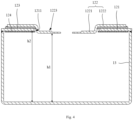
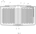
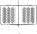
- the button cell provided by the embodiment of the present application includes: a housing 10, an electric core 20 located in an accommodating cavity 1011 of the housing 10, and a conductive member 30 arranged on and connected with the housing 10 in an insulated manner.
- the conductive member 30 is provided with a liquid injection port 301 for injecting electrolyte into the accommodating cavity 1011 and a covering member 40 for covering the liquid injection port 301, and the covering member 40 is hermetically connected with the liquid injection port 301.
- the electric core 20 is provided with a first tab 201 and a second tab 202.
- the first tab 201 is electrically connected with the housing 10 by welding, etc.
- the second tab 202 is electrically connected with the conductive member 30 by welding and bonding.
- the housing 10 and the conductive member 30 are each electrically connected with an electronic equipment, so that the electric core 20 may provide electric energy to the electronic equipment through the housing 10 and the conductive member 30.
- the housing 10 includes a bottom housing 101 and a head cover 102.
- the bottom housing 101 is provided with a groove extending towards a bottom wall of the bottom housing 101, the groove forms an accommodating cavity 1011 for accommodating the electric core 20, and the head cover 102 covers an opening communicated with the accommodating cavity 1011, so that the housing 10 with an accommodating cavity 1011 is formed by enclosing of the bottom housing 101 and the head cover 102.
- the head cover 102 and the bottom housing 101 are connected in a sealed manner, for example, the head cover 102 and the bottom housing 101 are welded, etc.
- the cross section of the housing 10 may be of any shape such as a circle, an ellipse, a polygon, etc., which is not limited in the present embodiment.
- the housing 10 and the conductive member 30 may be made of stainless steel, copper, iron and other metal materials.
- the head cover 102 is provided with a through hole 1021 to make the head cover 102 form a ring structure.
- the through hole 1021 is covered by the conductive member 30, and a sealing rubber ring 50 is arranged between the conductive member 30 and the through hole 1021.
- the sealing rubber ring 50 makes the conductive member 30 and the through hole 1021 connected in an insulated and sealed manner. That is, the conductive member 30 is bonded to the edge of the through hole 1021 through the sealing rubber ring 50, and covers the through hole 1021 of the head cover 102.
- the through hole 1021 may be circular, elliptical, polygonal, etc.
- the conductive member 30 may be bonded to the head cover 102 through the sealing rubber ring 50 by means of heating and pressurization. In this way, the bonding reliability of the sealing rubber ring 50 may be improved, thereby improving the sealing performance of connection between the conductive member 30 and the head cover 102.
- the conductive member 30 may protrude beyond the surface of the head cover 102, or the head cover 102 may also be provided with a holding groove 1022 for placing the conductive member. As shown in Fig. 12 , the conductive member 30 is located in the holding groove 1022, and the upper surface of the conductive member 30 is flush with that of the head cover 102.
- glue overflow will occur to the sealing rubber ring 50. In this way, the glue overflow is located in the holding groove 1022 and will not overflow the surface of the head cover 102. In this way, the surface of the head cover 102 is relatively flat, and the overall structure of the button cell is more compact, which improves the overall aesthetics of the button cell.
- the through hole 1021 is a circular hole
- the conductive member 30 is in a shape of disc
- the diameter of the through hole 1021 is smaller than that of the conductive member 30. Therefore, the edge of the conductive member 30 and the edge of the through hole 1021 are at least partially overlapped in a radial direction, and the through hole 1021 and the conductive member 30 are tightly bonded by heating and pressurizing through the sealing rubber ring 50, which can allow a tighter connection between the connection between the through hole 1021 and the conductive member 30 under high heat and high pressure, thereby improving the sealing performance of the button cell.
- the unilateral overlapped part of the conductive member 30 and the through hole 1021 in the radial direction is greater than or equal to 0.3mm in size. In this way, the sealing area between the conductive member 30 and the through hole 1021 is increased, so that the sealing performance between the conductive member 30 and the through hole 1021 is improved.
- the conductive member 30 is also provided with an extension 303 penetrating through the through hole 1021.
- the conductive member 30 is formed as a T-shaped conductive member 30.
- the extension 303 and the hole wall of the through hole 1021 are hermetically connected through the sealing rubber ring 50, which further increases the sealing area between the conductive member 30 and the through hole 1021, so that the sealing performance between the conductive member 30 and the through hole 1021 is improved.
- the sealing rubber ring 50 may be made of soluble material, which improves the corrosion resistance to electrolyte and the sealing performance of the sealing rubber ring 50.
- the sealing rubber ring 50 is annular. Upon heating and pressurizing of the conductive member 30 and the head cover 102, the outer edge of the sealing rubber ring 50 overflows the joint between the conductive member 30 and the head cover 102, and the inner edge of the sealing rubber ring 50 overflows the joint between the sealing rubber ring 50 and the edge of the through hole 1021 of the head cover 102. In this way, the connection reliability of the sealing rubber ring 50 in connecting with the conductive member and the head cover 102 can be guaranteed.
- the conductive member 30 is also provided with a liquid injection port 301 for injecting electrolyte into the accommodating cavity 1011.
- the liquid injection port 301 may be of any shape such as circle, quadrangle, polygon, etc.
- the liquid injection port 301 is concentric with the conductive member 30, and the conductive member 30 is concentric with the accommodating cavity 1011 in the housing 10 for accommodating the electric core 20.
- a counter bore 302 is arranged at one end of the liquid injection port 301 away from the accommodating cavity 1011, the diameter of the counter bore 302 is larger than that of the liquid injection port 301, and the counter bore 302 is communicated and coaxial with the liquid injection port 301.
- the shape of the counter bore 302 is the same as that of the liquid injection port 301, that is, when the liquid injection port 301 is circular, the counter bore 302 is also circular.
- the depth of the counter bore 302 may be between 0.01mm and 0.5mm.
- the liquid injection port 301 is covered with a covering member 40, that is, the covering member 40 is located in the counter bore 302. Due to the smaller depth of the counter bore 302, the covering member 40 may be a sheet structure, and located in the counter bore 302 to cover the liquid injection port 301.
- the covering member 40 is hermetically connected with the liquid injection port 301.
- the covering member 40 and the liquid injection port 301 may be welded with each other, that is, after the electrolyte is injected into the accommodating cavity 1011 through the liquid injection port 301, the joint between the covering member 40 and the counter bore 302 is subjected to welding outside of the housing 10, so as to improve the sealing performance.
- the covering member 40 may be a sealing nail which is located in the counter bore 302, and the sealing nail and the counter bore 302 are connected together by welding of their joint.
- the diameter of the counter bore 302 is larger than that of a nail cap of the sealing nail, and the part of the sealing nail which is located in the counter bore 302 has a welding mark. That is, a welding to the joint between the sealing nail and the conductive member 30 may be performed in the counter bore 302 by a welding equipment.
- the laser beam of a laser welding equipment may extend into the counter bore 302 to weld the sealing nail and the conductive member 30 together.
- the covering member 40 may also be located in the counter bore 302 and bonded with the counter bore by means of the sealing rubber ring and so on, so as to simplify the operation process.
- the electric core 20 is a winding-type electric core 20.
- the winding-type electric core 20 includes a first plate, a second plate and a diaphragm for separating the first plate from the second plate; the first plate is provided with a first tab 201, which may be arranged on the first plate by means of welding, and the second plate is provided with a second tab 202, which may be arranged on the second plate by welding.
- the first plate, the second plate and the diaphragm are wound layer by layer in the same direction from the initial end of winding, and finally form a winding-type electric core 20.
- the first plate of the electric core 20 may be a positive plate and the second plate may be a negative plate.
- the first tab 201 arranged on the first plate is a positive tab and the second tab 202 arranged on the second plate is a negative tab.
- the electric core 20 is contained in the accommodating cavity 1011, the positive tab is electrically connected with the inner bottom wall of the bottom housing 101 by means of welding to allow the bottom housing 101 to be formed as a positive electrode of the button cell, and the negative tab is electrically connected with the conductive member 30 to allow the conductive member 30 to be formed as a negative electrode of the button cell.
- the bottom housing 101 When the button cell is applied to the electronic equipment, the bottom housing 101 is connected with the positive electrode of the electronic equipment to be conductive, and the conductive member 30 is connected with the negative electrode of the electronic equipment to be conductive, so as to enable the electric core 20 to supply power to the electronic equipment.
- the first plate of the electric core 20 may be a negative plate and the second plate may be a positive plate.
- the first tab 201 arranged on the first plate is a negative tab and the second tab 202 arranged on the second plate is a positive tab.
- the electric core 20 is contained in the accommodating cavity 1011, the negative tab is electrically connected with the bottom housing 101 by means of welding to allow the bottom housing 101 to be formed as the negative electrode of the button cell, and the positive tab is electrically connected with the conductive member 30 to allow the conductive member 30 to be formed as the positive electrode of the button cell.
- the bottom housing 101 When the button cell is applied to the electronic equipment, the bottom housing 101 is connected with the negative electrode of the electronic equipment to be conductive, and the conductive member 30 is connected with the positive electrode of the electronic equipment to be conductive, so as to enable the electric core 20 to supply power to the electronic equipment.
- the second tab 202 is electrically connected with one end of the extension 303 of the conductive member 30 extending into the accommodating cavity 1011.
- the contact area between the second tab 202 and the conductive member 30 may be increased, so as to improve the reliability of the electrical connection.
- one end of the extension 303 facing the accommodating cavity 1011 exceeds the inner wall of the head cover 102.
- first tab 201 is electrically connected with the head cover 102 in the housing 10 by means of welding or bonding.
- an insulating layer may be disposed in the circumferential direction of the first tab 201 and the second tab 202, only exposing the part of the first tab 201 or the second tab 202 which is electrically connected with the bottom housing 101 or the conductive member 30, respectively.
- the winding-type electric core 20 may form an electric core cavity 203 in its center during winding.
- the electric core cavity 203 is arranged concentrically with the liquid injection port 301.
- the plates and diaphragm in the electric core 20 will not block the injection of the electrolyte, thereby improving the efficiency of the injection of electrolyte and enhancing the production efficiency of button cell.
- the butting piece 60 may also be inserted into the electric core cavity 203 from the liquid injection port 301.
- the butting piece 60 may be of a columnar structure, such as a cylinder, prism and other structures, may be composed of one columnar piece, or may be composed of two or more columnar pieces connected from head to tail in sequence.
- the butting piece 60 is first inserted into the electric core cavity 203, so as to make a first end of the butting piece 60 butted to the first tab 201, and a pressure is applied on a second end of the butting piece 60 to make the first tab 201 tightly contact with the inner bottom wall of the bottom housing 101 through the extrusion of the butting piece 60, followed by welding.
- the reliability of welding between the first tab 201 and the bottom housing 101 may be improved, thereby improving the reliability of the electrical connection between the first tab 201 and the bottom housing 101.
- the second end of the butting piece 60 may protrude out of the head cover 102 of the housing 10. After the welding of the first tab 201 in the button cell with the inner bottom wall of the bottom housing 101 is completed and the head cover 102 provided with the conductive member 30 is hermetically connected with the bottom housing 101, the butting piece 60 may be taken out from the electric core cavity 203 along the liquid injection port 301.
- a vibration may occur. If the bottom housing 101 and the head cover 102 are first hermetically connected and then the first tab 201 is welded with the bottom housing 101, the vibration will occur, resulting in an offset between the bottom housing 101 and the head cover 102 and a dislocation between the bottom housing 101 and the head cover 102, which causes loosening or failure of the sealed connection between the bottom housing 101 and the head cover 102 and finally leads to bad sealing performance of the button electric core. Therefore, in this embodiment, the electric core 20 provided with the first tab 201 and the second tab 202 is first placed in the accommodating cavity 1011 of the bottom housing 101, and the butting piece 60 is inserted into the electric core cavity 203 of the electric core 20.
- the first tab 201 is tightly contact with the inner bottom wall of the bottom housing 101 under the extrusion of the butting piece 60, and then the bottom housing 101 and the first tab 201 are welded by a welding equipment to realize the electric connection between the first tab 201 and the bottom housing 101. Then, the head cover 102 provided with the conductive member 30 is connected in a sealed manner with the bottom housing 101 by welding or bonding.
- the head cover 102 and the conductive member 30 are connected together in an insulated and sealed manner via the sealing rubber ring 50 by means of heating and pressurization, and then the electric core 20 is placed into the accommodating cavity 1011 in the bottom housing 101 and the butting piece 60 is inserted into the electric core cavity 203.
- the first end of the butting piece 60 is butted on the first tab 201, and the second end of the butting piece 60 extends out of the head cover 102. Under the extrusion of the butting piece 60, the first tab 201 is tightly contact with the inner bottom wall of the bottom housing 101.
- the first tab 201 is welded with the bottom housing 101 through a welding equipment, and then the head cover 102 provided with the conductive member 30 covers the bottom housing 101.
- the bottom housing 101 and the head cover 102 are connected in a sealed manner by bonding or welding, and the second tab 202 of the electric core 20 is electrically connected with the conductive member 30.
- the electrolyte is injected into the accommodating cavity from the liquid injection port 301.
- the liquid injection port 301 is covered by the covering member 40, and the covering member 40 is hermetically connected with the liquid injection port 301 by bonding or welding.
- a through hole of a head cover is covered by a conductive member, the head cover and the conductive member are connected together in an insulated and sealed manner through a sealing rubber ring, an electric core is placed in an accommodating cavity of a bottom housing so as to make a first tab of the electric core welded with an inner bottom wall of the bottom housing, and then the head cover provided with the conductive member is hermetically connected with the bottom housing so as to make a second tab of the electric core electrically connected with the conductive member. Finally, the head cover provided with the conductive member is hermetically connected with the bottom housing, and the electrolyte is injected into the accommodating cavity from a liquid injection port of the conductive member. After the injection of electrolyte is completed, a covering member covers the liquid injection port and is connected with the liquid injection port in a sealed manner by bonding or welding, thereby improving the sealing performance of the button cell.
- the embodiment of the present application also provides an electronic equipment, including an electronic equipment body and a button cell provided in Embodiment 1, and the button cell provides electric energy for the electronic equipment body.
- the electronic equipment provided by the present application includes an electronic equipment body and a button cell that provides electric energy for the electronic equipment body.
- a through hole of a head cover is covered by a conductive member, the head cover and the conductive member are connected together in an insulated and sealed manner through a sealing rubber ring, an electric core is placed in an accommodating cavity of a bottom housing so as to make a first tab of the electric core welded with an inner bottom wall of the bottom housing, and then the head cover provided with the conductive member is hermetically connected with the bottom housing so as to make a second tab of the electric core electrically connected with the conductive member; finally, the head cover provided with the conductive member is hermetically connected with the bottom housing, and the electrolyte is injected into the accommodating cavity from a liquid injection port of the conductive member; after the injection of electrolyte is completed, a covering member covers the liquid injection port and is connected with the liquid injection port in a sealed manner by bonding or welding, thereby improving the sealing performance of the button cell.
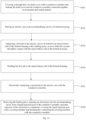
- the embodiment of the present application also provides a manufacturing method of a button cell, which includes the following steps.
- a through hole of a head cover is covered by a conductive member, and the head cover and the conductive member are connected together in an insulated and sealed manner.
- a sealing rubber ring is disposed between the head cover and the conductive member.
- the head cover and the conductive member are extruded and connected together by means of heating and pressurizing, and the sealing rubber ring is deformed by extrusion, so as to improve the sealing performance between the head cover and the conductive member.
- an electric core is placed in an accommodating cavity of a bottom housing.
- a first tab in the electric core is subjected to be butted to an inner bottom wall of the bottom housing with a butting piece to make the first tab tightly contact with the inner bottom wall of the bottom housing.
- the first tab is welded to the inner bottom wall of the bottom housing.
- a second tab in the electric core is electrically connected with the conductive member.
- the butting piece is removed and an electrolyte is injected into the accommodating cavity from a liquid injection port in the conductive member.
- a covering member covers the liquid injection port and is hermetically connected with the conductive member.
- the second tab in the electric core is first electrically connected with the conductive member before the head cover provided with the conductive member is hermetically connected with the bottom housing.
- the following step is further included.
- a passivation treatment is performed on the head cover and the conductive member.
- the passivation treatment refers to a process that metal is oxidized by a strong oxidant or an electrochemical method to make its surface inactive, i.e. passivated. This treatment is a method to transform the metal surface into a state that is not easy to be oxidized so as to delay the corrosion rate of the metal.
- the following step is further included.
- the butting piece that is placed in the electric core cavity is extruded from the liquid injection port; and the butting piece extrudes the first tab in the electrode core to make it tightly contact with the inner bottom wall of the housing.
- the through hole of the head cover is covered by the conductive member, the head cover and the conductive member are connected together in an insulated and sealed manner through the sealing rubber ring, the electric core is placed in the accommodating cavity of the bottom housing so as to make the first tab of the electric core welded with the inner bottom wall of the bottom housing, and then the head cover provided with the conductive member is hermetically connected with the bottom housing so as to make the second tab of the electric core electrically connected with the conductive member; finally, the electrolyte is injected into the accommodating cavity from a liquid injection port of the conductive member; after the injection of electrolyte is completed, the covering member covers the liquid injection port and is connected with the liquid injection port in a sealed manner, thereby improving the sealing performance of the button cell.
- the embodiment of the present application further provides another manufacturing method of a button cell, the following steps are included.
- a head cover and a conductive member are connected together in an insulated and sealed manner, where a through hole of the head cover is covered by the conductive member.
- a second tab in an electric core is electrically connected with the conductive member.
- the electric core that is electrically connected with the conductive member is placed in an accommodating cavity formed by enclosing of a bottom housing and the head cover that is provided with the conductive member.
- the head cover provided with conductive member is hermetically connected with the bottom housing.
- a first tab in the electric core is welded with the bottom housing.
- an electrolyte is injected into the accommodating cavity from a liquid injection port of the conductive member, and after the injection of electrolyte is completed, a covering member covers the liquid injection port and is hermetically connected with the conductive member.
- the second tab in the electrode core is electrically connected with the conductive member.
- the head cover and the conductive member are connected in an insulated and sealed manner through the sealing rubber ring by means of heating and pressurization, the conductive member is electrically connected with the second tab, the electrode core that is electrically connected with the conductive member through the second tab is placed in the accommodating cavity, the bottom housing is covered by the head cover provided with the conductive member, and the bottom housing is hermetically connected with the head cover by bonding or welding.
- the butting piece may be inserted from the liquid injection port and butted to the first tab so as to make the first tab tightly contact with the inner bottom wall of the bottom housing.
- the first tab is welded to the bottom housing by a welding equipment, and then the butting piece is taken out from the liquid injection port, and the covering member covers the liquid injection port and is bonded to the conductive member by welding or bonding.
- a seal may also be added at the covering member and the liquid injection port, so as to improve the sealing performance of the button cell.
- welding the bottom housing and the head cover first and then welding the first tab and the inner bottom wall of the bottom housing can improve the welding reliability of the first tab and the bottom housing, thereby improving the electrical connection reliability between the first tab and the bottom housing.
Landscapes
- Chemical & Material Sciences (AREA)
- Chemical Kinetics & Catalysis (AREA)
- Electrochemistry (AREA)
- General Chemical & Material Sciences (AREA)
- Engineering & Computer Science (AREA)
- Manufacturing & Machinery (AREA)
- Filling, Topping-Up Batteries (AREA)
- Sealing Battery Cases Or Jackets (AREA)
- Connection Of Batteries Or Terminals (AREA)
Applications Claiming Priority (3)
| Application Number | Priority Date | Filing Date | Title |
|---|---|---|---|
| CN202010496417.7A CN111613739B (zh) | 2020-06-03 | 2020-06-03 | 扣式电池及其制造方法、电子设备 |
| CN202110394741.2A CN112993452A (zh) | 2021-04-13 | 2021-04-13 | 扣式电池及电子设备 |
| PCT/CN2021/098182 WO2021244618A1 (zh) | 2020-06-03 | 2021-06-03 | 扣式电池及其制造方法、电子设备 |
Publications (2)
| Publication Number | Publication Date |
|---|---|
| EP4152489A1 true EP4152489A1 (de) | 2023-03-22 |
| EP4152489A4 EP4152489A4 (de) | 2024-02-28 |
Family
ID=78830130
Family Applications (1)
| Application Number | Title | Priority Date | Filing Date |
|---|---|---|---|
| EP21818153.5A Pending EP4152489A4 (de) | 2020-06-03 | 2021-06-03 | Knopfzelle und herstellungsverfahren dafür sowie elektronische vorrichtung |
Country Status (5)
| Country | Link |
|---|---|
| US (1) | US12580286B2 (de) |
| EP (1) | EP4152489A4 (de) |
| JP (1) | JP7549046B2 (de) |
| KR (1) | KR102919244B1 (de) |
| WO (1) | WO2021244618A1 (de) |
Cited By (1)
| Publication number | Priority date | Publication date | Assignee | Title |
|---|---|---|---|---|
| WO2023144052A1 (de) * | 2022-01-25 | 2023-08-03 | Bayerische Motoren Werke Aktiengesellschaft | Batteriezellgehäuse für eine batteriezelle eines elektrischen energiespeichers sowie batteriezelle |
Families Citing this family (23)
| Publication number | Priority date | Publication date | Assignee | Title |
|---|---|---|---|---|
| KR20230023608A (ko) | 2020-03-18 | 2023-02-17 | 주하이 코스엠엑스 배터리 컴퍼니 리미티드 | 배터리 케이스, 배터리 및 전자기기 |
| WO2021244272A1 (zh) | 2020-06-03 | 2021-12-09 | 珠海冠宇电池股份有限公司 | 扣式电池及电子设备 |
| US11862806B2 (en) * | 2020-06-03 | 2024-01-02 | Zhuhai Cosmx Battery Co., Ltd. | Button cell and electronic device |
| EP4152489A4 (de) | 2020-06-03 | 2024-02-28 | Zhuhai CosMX Battery Co., Ltd. | Knopfzelle und herstellungsverfahren dafür sowie elektronische vorrichtung |
| CN111682129A (zh) * | 2020-06-05 | 2020-09-18 | 重庆市紫建电子股份有限公司 | 一种金属壳扣式锂离子电池 |
| USD1096608S1 (en) * | 2020-06-29 | 2025-10-07 | Zhuhai Cosmx Battery Co., Ltd. | Button cell |
| CN213520130U (zh) * | 2020-12-04 | 2021-06-22 | 珠海冠宇电池股份有限公司 | 扣式电池及电子设备 |
| USD1093278S1 (en) * | 2021-01-25 | 2025-09-16 | Zhuhai Cosmx Battery Co., Ltd. | Battery |
| USD1104945S1 (en) * | 2021-02-23 | 2025-12-09 | Zhuhai Cosmx Battery Co., Ltd. | Battery |
| JP1715351S (ja) * | 2021-08-27 | 2022-05-18 | ボタン電池 | |
| CN114204108A (zh) * | 2021-12-13 | 2022-03-18 | 珠海冠宇电池股份有限公司 | 一种电池 |
| CN114122587A (zh) * | 2021-12-17 | 2022-03-01 | 珠海冠宇电池股份有限公司 | 一种电池 |
| CN216563341U (zh) * | 2021-12-22 | 2022-05-17 | 珠海冠宇电池股份有限公司 | 电池及电子设备 |
| CN114927809A (zh) * | 2022-06-29 | 2022-08-19 | 深圳市聚和源科技有限公司 | 一种无边圆柱电池结构及其制备方法 |
| JP7750194B2 (ja) * | 2022-08-29 | 2025-10-07 | 株式会社村田製作所 | 電池 |
| CN115415766B (zh) * | 2022-09-27 | 2023-06-20 | 东莞士格电子集团有限公司 | 纽扣电池的正极壳和负极壳的一体式组装设备 |
| CN219203434U (zh) * | 2022-12-29 | 2023-06-16 | 远景动力技术(江苏)有限公司 | 一种圆柱电池及电子设备 |
| KR20240110400A (ko) * | 2023-01-06 | 2024-07-15 | 삼성에스디아이 주식회사 | 버튼 전지 |
| USD1030638S1 (en) * | 2023-05-08 | 2024-06-11 | Shenzhen Juheyuan Technology Co., Ltd. | Battery |
| CN116487781A (zh) * | 2023-06-02 | 2023-07-25 | 湖州耀宁固态能源科技有限公司 | 一种电芯、电芯模组及用电装置 |
| CN117276773A (zh) * | 2023-10-19 | 2023-12-22 | 深圳市铭杰泰科技有限公司 | 一种电池外壳及扣式电池 |
| USD1119756S1 (en) * | 2024-08-15 | 2026-03-24 | Broadata Communications, Inc. | Battery pack for wireless cart |
| CN119764475B (zh) * | 2024-12-31 | 2026-01-20 | 蜂巢能源科技股份有限公司 | 电池装配方法及电池 |
Family Cites Families (55)
| Publication number | Priority date | Publication date | Assignee | Title |
|---|---|---|---|---|
| JPH0821386B2 (ja) * | 1988-08-29 | 1996-03-04 | 日立マクセル株式会社 | 扁平形非水液体活物質電池 |
| US5578392A (en) | 1995-02-17 | 1996-11-26 | Japan Storage Battery Co., Ltd. | Cylindrical cell, a cell pack, and a cell holder |
| JP4111621B2 (ja) | 1999-03-17 | 2008-07-02 | 三洋電機株式会社 | 密閉式電池、密閉式電池用封止栓及び注液孔封止方法 |
| WO2001082397A1 (en) | 2000-04-26 | 2001-11-01 | Quallion, Llc | Lithium battery suitable for hybrid electric vehicles |
| EP1295851A4 (de) | 2000-11-16 | 2008-08-20 | Hitachi Maxell | Lithiumhaltiges kompositoxid und nichtwässrige sekundäre zelle dieses vrwendend, und verfahren zur herstellung desselben |
| US6586134B2 (en) | 2001-03-29 | 2003-07-01 | Wilson Greatbatch Ltd. | Electrode lead to case and header, laser/electron beam welding |
| JP4436587B2 (ja) | 2002-01-31 | 2010-03-24 | パナソニック株式会社 | 電池及び組電池 |
| US7341802B1 (en) * | 2004-03-25 | 2008-03-11 | Quallion Llc | Feedthrough assembly and method |
| KR100624934B1 (ko) | 2004-10-28 | 2006-09-15 | 삼성에스디아이 주식회사 | 원통형 리튬 이차 전지 |
| CN2833898Y (zh) | 2005-08-19 | 2006-11-01 | 周基平 | 锂离子电池盖板组件及电池 |
| CN101305481B (zh) | 2005-09-02 | 2011-01-12 | A123系统公司 | 电池设计及其构造方法 |
| CN201436694U (zh) | 2009-06-24 | 2010-04-07 | 东莞新能源科技有限公司 | 动力电池注液及防爆装置 |
| JP2011216479A (ja) * | 2010-03-18 | 2011-10-27 | Panasonic Corp | コイン形電池およびコイン形電池用ホルダとコイン形電池収納体 |
| US9564654B2 (en) * | 2010-09-14 | 2017-02-07 | Zhuhai Zhi Li Battery Co. Ltd. | Rechargeable lithium ion button cell battery |
| JP6045783B2 (ja) * | 2011-01-25 | 2016-12-14 | 株式会社東芝 | 二次電池及び二次電池の製造方法 |
| WO2012147375A1 (ja) | 2011-04-27 | 2012-11-01 | 日立マクセルエナジー株式会社 | 電池ユニット |
| JP6017873B2 (ja) * | 2012-07-27 | 2016-11-02 | トヨタ自動車株式会社 | 密閉型電池 |
| US20150047180A1 (en) | 2013-08-14 | 2015-02-19 | The Gillette Company | Battery manufacturing |
| JP6269198B2 (ja) | 2014-03-12 | 2018-01-31 | 株式会社Gsユアサ | 蓄電素子及び蓄電素子の製造方法 |
| FR3034912B1 (fr) | 2015-04-10 | 2021-12-10 | Compagnie Ind Et Financiere Dingenierie Ingenico | Pile sertie, circuit imprime et procede de montage correspondant |
| CN204596910U (zh) | 2015-04-27 | 2015-08-26 | 深圳金山电池有限公司 | 一种纽扣型锂离子二次电池 |
| CN106159350B (zh) * | 2015-04-27 | 2019-04-26 | 深圳金山电池有限公司 | 一种纽扣型锂离子二次电池及其制备方法 |
| KR102512351B1 (ko) | 2015-12-14 | 2023-03-22 | 삼성에스디아이 주식회사 | 이차 전지 |
| KR102061293B1 (ko) | 2015-12-23 | 2019-12-31 | 주식회사 엘지화학 | 이차전지 팩 |
| JP6288065B2 (ja) * | 2015-12-24 | 2018-03-07 | トヨタ自動車株式会社 | 二次電池の製造方法 |
| US10366844B2 (en) | 2016-01-15 | 2019-07-30 | Seiko Instruments Inc. | Electrochemical cell |
| CN106654077A (zh) * | 2017-01-23 | 2017-05-10 | 珠海微矩实业有限公司 | 纽扣电池 |
| DE112018003611T5 (de) | 2017-07-14 | 2020-05-20 | Gs Yuasa International Ltd. | Energiespeicher |
| JP7205050B2 (ja) | 2017-09-01 | 2023-01-17 | 株式会社村田製作所 | 密閉型蓄電装置 |
| CN107768586A (zh) * | 2017-09-28 | 2018-03-06 | 珠海微矩实业有限公司 | 纽扣电池及其装置 |
| CN207282605U (zh) | 2017-09-28 | 2018-04-27 | 珠海微矩实业有限公司 | 纽扣电池及其装置 |
| CN108172700A (zh) | 2017-12-15 | 2018-06-15 | 珠海微矩实业有限公司 | 纽扣电池及其制作方法 |
| CN207651537U (zh) | 2017-12-15 | 2018-07-24 | 珠海微矩实业有限公司 | 纽扣电池 |
| CN108023037B (zh) * | 2017-12-15 | 2024-06-25 | 珠海微矩实业有限公司 | 纽扣电池 |
| JP7089895B2 (ja) | 2018-02-22 | 2022-06-23 | 株式会社ブルーエナジー | 蓄電素子 |
| KR102622370B1 (ko) | 2018-08-16 | 2024-01-09 | 주식회사 엘지에너지솔루션 | 이차전지 |
| CN109192889B (zh) * | 2018-08-22 | 2024-01-26 | 珠海微矩实业有限公司 | 一种微型电池 |
| CN209804717U (zh) | 2019-03-07 | 2019-12-17 | 广东微电新能源有限公司 | 一种纽扣电池 |
| CN210224214U (zh) * | 2019-08-24 | 2020-03-31 | 重庆市紫建电子有限公司 | 一种带有绝缘针或金属针电芯的卷绕型纽扣电池 |
| CN110459705A (zh) * | 2019-09-05 | 2019-11-15 | 重庆市紫建电子有限公司 | 一种提升径向空间利用率的纽扣电池 |
| CN110828885A (zh) | 2019-11-11 | 2020-02-21 | 中山市众旺德新能源科技有限公司 | 一种扣式柱状锂离子电池及制造方法 |
| KR102471745B1 (ko) | 2020-02-03 | 2022-11-25 | 삼성에스디아이 주식회사 | 이차 전지 |
| CN211238301U (zh) | 2020-03-18 | 2020-08-11 | 珠海冠宇电池股份有限公司 | 一种密封壳体结构及电池 |
| CN212434725U (zh) | 2020-07-08 | 2021-01-29 | 珠海冠宇电池股份有限公司 | 扣式电池及电子设备 |
| KR20230023608A (ko) | 2020-03-18 | 2023-02-17 | 주하이 코스엠엑스 배터리 컴퍼니 리미티드 | 배터리 케이스, 배터리 및 전자기기 |
| CN211404538U (zh) | 2020-03-30 | 2020-09-01 | 珠海冠宇电池股份有限公司 | 扣式电池的外壳组件、扣式电池以及电子产品 |
| US11862806B2 (en) | 2020-06-03 | 2024-01-02 | Zhuhai Cosmx Battery Co., Ltd. | Button cell and electronic device |
| WO2021244272A1 (zh) | 2020-06-03 | 2021-12-09 | 珠海冠宇电池股份有限公司 | 扣式电池及电子设备 |
| CN111613739B (zh) * | 2020-06-03 | 2024-05-24 | 珠海冠宇电池股份有限公司 | 扣式电池及其制造方法、电子设备 |
| CN212434722U (zh) | 2020-06-03 | 2021-01-29 | 珠海冠宇电池股份有限公司 | 扣式电池及电子设备 |
| EP4152489A4 (de) | 2020-06-03 | 2024-02-28 | Zhuhai CosMX Battery Co., Ltd. | Knopfzelle und herstellungsverfahren dafür sowie elektronische vorrichtung |
| CN112531242A (zh) * | 2020-12-04 | 2021-03-19 | 珠海冠宇电池股份有限公司 | 扣式电池及电子设备 |
| KR102868036B1 (ko) | 2020-06-25 | 2025-10-01 | 삼성에스디아이 주식회사 | 이차 전지 |
| CN111900275A (zh) * | 2020-08-04 | 2020-11-06 | 珠海冠宇电池股份有限公司 | 扣式电池及其制备方法 |
| CN214411334U (zh) | 2021-04-13 | 2021-10-15 | 珠海冠宇电池股份有限公司 | 电池及电子设备 |
-
2021
- 2021-06-03 EP EP21818153.5A patent/EP4152489A4/de active Pending
- 2021-06-03 WO PCT/CN2021/098182 patent/WO2021244618A1/zh not_active Ceased
- 2021-06-03 JP JP2022574616A patent/JP7549046B2/ja active Active
- 2021-06-03 KR KR1020227043999A patent/KR102919244B1/ko active Active
-
2022
- 2022-12-02 US US18/061,402 patent/US12580286B2/en active Active
Cited By (1)
| Publication number | Priority date | Publication date | Assignee | Title |
|---|---|---|---|---|
| WO2023144052A1 (de) * | 2022-01-25 | 2023-08-03 | Bayerische Motoren Werke Aktiengesellschaft | Batteriezellgehäuse für eine batteriezelle eines elektrischen energiespeichers sowie batteriezelle |
Also Published As
| Publication number | Publication date |
|---|---|
| EP4152489A4 (de) | 2024-02-28 |
| US20230106855A1 (en) | 2023-04-06 |
| KR20230021666A (ko) | 2023-02-14 |
| WO2021244618A1 (zh) | 2021-12-09 |
| US12580286B2 (en) | 2026-03-17 |
| JP7549046B2 (ja) | 2024-09-10 |
| KR102919244B1 (ko) | 2026-01-27 |
| JP2023529378A (ja) | 2023-07-10 |
Similar Documents
| Publication | Publication Date | Title |
|---|---|---|
| US12580286B2 (en) | Button cell and manufacturing method thereof and electronic equipment | |
| CN111613739B (zh) | 扣式电池及其制造方法、电子设备 | |
| US12469905B2 (en) | Button cell and electronic equipment | |
| CN212434722U (zh) | 扣式电池及电子设备 | |
| EP3920298B1 (de) | Knopfzelle und elektronische vorrichtung | |
| JP7788472B2 (ja) | 電池及び電子製品 | |
| WO2021082218A1 (zh) | 密封组件及锂离子电池 | |
| CN113964424A (zh) | 一种电池 | |
| CN114944531B (zh) | 圆柱型电池盖板组件、电池及制备方法 | |
| WO2017115854A1 (ja) | 蓄電素子及び蓄電素子の製造方法 | |
| WO2025108164A1 (zh) | 密封件、电池模组及用电设备 | |
| CN219086102U (zh) | 螺纹式密封的高倍率圆柱电池 | |
| US20230013297A1 (en) | Case component for battery, battery, and material belt | |
| WO2021088886A1 (zh) | 纽扣电池 | |
| CN214411334U (zh) | 电池及电子设备 | |
| CN219677326U (zh) | 一种圆柱电池 | |
| CN217641480U (zh) | 一种电芯 | |
| CN218385436U (zh) | 一种电池及其电池外壳 | |
| CN117335014A (zh) | 裸电芯、圆柱电池及圆柱电池的装配方法 | |
| CN116646656A (zh) | 易于装配的圆筒形二次电池 | |
| JP4244580B2 (ja) | 密閉型電池 | |
| CN223193946U (zh) | 电池结构组件及电池 | |
| CN221861891U (zh) | 一种钢壳电池 | |
| WO2024239279A1 (zh) | 一种扣式电池及电子设备 | |
| JP2010205701A (ja) | 扁平形二次電池 |
Legal Events
| Date | Code | Title | Description |
|---|---|---|---|
| STAA | Information on the status of an ep patent application or granted ep patent |
Free format text: STATUS: THE INTERNATIONAL PUBLICATION HAS BEEN MADE |
|
| PUAI | Public reference made under article 153(3) epc to a published international application that has entered the european phase |
Free format text: ORIGINAL CODE: 0009012 |
|
| STAA | Information on the status of an ep patent application or granted ep patent |
Free format text: STATUS: REQUEST FOR EXAMINATION WAS MADE |
|
| 17P | Request for examination filed |
Effective date: 20221213 |
|
| AK | Designated contracting states |
Kind code of ref document: A1 Designated state(s): AL AT BE BG CH CY CZ DE DK EE ES FI FR GB GR HR HU IE IS IT LI LT LU LV MC MK MT NL NO PL PT RO RS SE SI SK SM TR |
|
| DAV | Request for validation of the european patent (deleted) | ||
| DAX | Request for extension of the european patent (deleted) | ||
| REG | Reference to a national code |
Ref country code: DE Ref legal event code: R079 Free format text: PREVIOUS MAIN CLASS: H01M0050109000 Ipc: H01M0010040000 |
|
| A4 | Supplementary search report drawn up and despatched |
Effective date: 20240131 |
|
| RIC1 | Information provided on ipc code assigned before grant |
Ipc: H01M 50/627 20210101ALI20240125BHEP Ipc: H01M 50/536 20210101ALI20240125BHEP Ipc: H01M 50/183 20210101ALI20240125BHEP Ipc: H01M 50/153 20210101ALI20240125BHEP Ipc: H01M 50/109 20210101ALI20240125BHEP Ipc: H01M 10/04 20060101AFI20240125BHEP |