EP4151823A1 - Système d'étanchéité de porte pour une porte coulissante suspendue par le dessus - Google Patents
Système d'étanchéité de porte pour une porte coulissante suspendue par le dessus Download PDFInfo
- Publication number
- EP4151823A1 EP4151823A1 EP22205923.0A EP22205923A EP4151823A1 EP 4151823 A1 EP4151823 A1 EP 4151823A1 EP 22205923 A EP22205923 A EP 22205923A EP 4151823 A1 EP4151823 A1 EP 4151823A1
- Authority
- EP
- European Patent Office
- Prior art keywords
- carriage
- door
- seal assembly
- door panel
- drop
- Prior art date
- Legal status (The legal status is an assumption and is not a legal conclusion. Google has not performed a legal analysis and makes no representation as to the accuracy of the status listed.)
- Pending
Links
- 239000012190 activator Substances 0.000 claims abstract description 37
- 238000009434 installation Methods 0.000 abstract description 5
- 238000000034 method Methods 0.000 abstract description 4
- 230000004913 activation Effects 0.000 abstract description 3
- 238000001125 extrusion Methods 0.000 description 35
- 239000002184 metal Substances 0.000 description 7
- 238000007789 sealing Methods 0.000 description 6
- 230000007246 mechanism Effects 0.000 description 4
- 230000008901 benefit Effects 0.000 description 3
- 230000005540 biological transmission Effects 0.000 description 3
- 238000010586 diagram Methods 0.000 description 3
- 230000001846 repelling effect Effects 0.000 description 2
- 230000009471 action Effects 0.000 description 1
- 230000004888 barrier function Effects 0.000 description 1
- 238000006073 displacement reaction Methods 0.000 description 1
- 238000009408 flooring Methods 0.000 description 1
- 239000000463 material Substances 0.000 description 1
- 230000008569 process Effects 0.000 description 1
- 230000009467 reduction Effects 0.000 description 1
Images


Classifications
-
- E—FIXED CONSTRUCTIONS
- E06—DOORS, WINDOWS, SHUTTERS, OR ROLLER BLINDS IN GENERAL; LADDERS
- E06B—FIXED OR MOVABLE CLOSURES FOR OPENINGS IN BUILDINGS, VEHICLES, FENCES OR LIKE ENCLOSURES IN GENERAL, e.g. DOORS, WINDOWS, BLINDS, GATES
- E06B7/00—Special arrangements or measures in connection with doors or windows
- E06B7/16—Sealing arrangements on wings or parts co-operating with the wings
- E06B7/18—Sealing arrangements on wings or parts co-operating with the wings by means of movable edgings, e.g. draught sealings additionally used for bolting, e.g. by spring force or with operating lever
- E06B7/20—Sealing arrangements on wings or parts co-operating with the wings by means of movable edgings, e.g. draught sealings additionally used for bolting, e.g. by spring force or with operating lever automatically withdrawn when the wing is opened, e.g. by means of magnetic attraction, a pin or an inclined surface, especially for sills
- E06B7/215—Sealing arrangements on wings or parts co-operating with the wings by means of movable edgings, e.g. draught sealings additionally used for bolting, e.g. by spring force or with operating lever automatically withdrawn when the wing is opened, e.g. by means of magnetic attraction, a pin or an inclined surface, especially for sills with sealing strip being moved to a retracted position by elastic means, e.g. springs
-
- E—FIXED CONSTRUCTIONS
- E06—DOORS, WINDOWS, SHUTTERS, OR ROLLER BLINDS IN GENERAL; LADDERS
- E06B—FIXED OR MOVABLE CLOSURES FOR OPENINGS IN BUILDINGS, VEHICLES, FENCES OR LIKE ENCLOSURES IN GENERAL, e.g. DOORS, WINDOWS, BLINDS, GATES
- E06B7/00—Special arrangements or measures in connection with doors or windows
- E06B7/16—Sealing arrangements on wings or parts co-operating with the wings
- E06B7/18—Sealing arrangements on wings or parts co-operating with the wings by means of movable edgings, e.g. draught sealings additionally used for bolting, e.g. by spring force or with operating lever
- E06B7/20—Sealing arrangements on wings or parts co-operating with the wings by means of movable edgings, e.g. draught sealings additionally used for bolting, e.g. by spring force or with operating lever automatically withdrawn when the wing is opened, e.g. by means of magnetic attraction, a pin or an inclined surface, especially for sills
- E06B7/21—Sealing arrangements on wings or parts co-operating with the wings by means of movable edgings, e.g. draught sealings additionally used for bolting, e.g. by spring force or with operating lever automatically withdrawn when the wing is opened, e.g. by means of magnetic attraction, a pin or an inclined surface, especially for sills with sealing strip movable in plane of wing
-
- E—FIXED CONSTRUCTIONS
- E05—LOCKS; KEYS; WINDOW OR DOOR FITTINGS; SAFES
- E05D—HINGES OR SUSPENSION DEVICES FOR DOORS, WINDOWS OR WINGS
- E05D15/00—Suspension arrangements for wings
- E05D15/06—Suspension arrangements for wings for wings sliding horizontally more or less in their own plane
- E05D15/0621—Details, e.g. suspension or supporting guides
- E05D15/0626—Details, e.g. suspension or supporting guides for wings suspended at the top
- E05D15/0656—Bottom guides
-
- E—FIXED CONSTRUCTIONS
- E06—DOORS, WINDOWS, SHUTTERS, OR ROLLER BLINDS IN GENERAL; LADDERS
- E06B—FIXED OR MOVABLE CLOSURES FOR OPENINGS IN BUILDINGS, VEHICLES, FENCES OR LIKE ENCLOSURES IN GENERAL, e.g. DOORS, WINDOWS, BLINDS, GATES
- E06B3/00—Window sashes, door leaves, or like elements for closing wall or like openings; Layout of fixed or moving closures, e.g. windows in wall or like openings; Features of rigidly-mounted outer frames relating to the mounting of wing frames
- E06B3/32—Arrangements of wings characterised by the manner of movement; Arrangements of movable wings in openings; Features of wings or frames relating solely to the manner of movement of the wing
- E06B3/34—Arrangements of wings characterised by the manner of movement; Arrangements of movable wings in openings; Features of wings or frames relating solely to the manner of movement of the wing with only one kind of movement
- E06B3/42—Sliding wings; Details of frames with respect to guiding
- E06B3/46—Horizontally-sliding wings
- E06B3/4636—Horizontally-sliding wings for doors
-
- E—FIXED CONSTRUCTIONS
- E06—DOORS, WINDOWS, SHUTTERS, OR ROLLER BLINDS IN GENERAL; LADDERS
- E06B—FIXED OR MOVABLE CLOSURES FOR OPENINGS IN BUILDINGS, VEHICLES, FENCES OR LIKE ENCLOSURES IN GENERAL, e.g. DOORS, WINDOWS, BLINDS, GATES
- E06B7/00—Special arrangements or measures in connection with doors or windows
- E06B7/16—Sealing arrangements on wings or parts co-operating with the wings
- E06B7/18—Sealing arrangements on wings or parts co-operating with the wings by means of movable edgings, e.g. draught sealings additionally used for bolting, e.g. by spring force or with operating lever
- E06B7/20—Sealing arrangements on wings or parts co-operating with the wings by means of movable edgings, e.g. draught sealings additionally used for bolting, e.g. by spring force or with operating lever automatically withdrawn when the wing is opened, e.g. by means of magnetic attraction, a pin or an inclined surface, especially for sills
-
- E—FIXED CONSTRUCTIONS
- E06—DOORS, WINDOWS, SHUTTERS, OR ROLLER BLINDS IN GENERAL; LADDERS
- E06B—FIXED OR MOVABLE CLOSURES FOR OPENINGS IN BUILDINGS, VEHICLES, FENCES OR LIKE ENCLOSURES IN GENERAL, e.g. DOORS, WINDOWS, BLINDS, GATES
- E06B7/00—Special arrangements or measures in connection with doors or windows
- E06B7/16—Sealing arrangements on wings or parts co-operating with the wings
- E06B7/22—Sealing arrangements on wings or parts co-operating with the wings by means of elastic edgings, e.g. elastic rubber tubes; by means of resilient edgings, e.g. felt or plush strips, resilient metal strips
- E06B7/23—Plastic, sponge rubber, or like strips or tubes
- E06B7/2316—Plastic, sponge rubber, or like strips or tubes used as a seal between the floor and the wing
-
- E—FIXED CONSTRUCTIONS
- E05—LOCKS; KEYS; WINDOW OR DOOR FITTINGS; SAFES
- E05Y—INDEXING SCHEME ASSOCIATED WITH SUBCLASSES E05D AND E05F, RELATING TO CONSTRUCTION ELEMENTS, ELECTRIC CONTROL, POWER SUPPLY, POWER SIGNAL OR TRANSMISSION, USER INTERFACES, MOUNTING OR COUPLING, DETAILS, ACCESSORIES, AUXILIARY OPERATIONS NOT OTHERWISE PROVIDED FOR, APPLICATION THEREOF
- E05Y2800/00—Details, accessories and auxiliary operations not otherwise provided for
- E05Y2800/40—Physical or chemical protection
- E05Y2800/422—Physical or chemical protection against vibration or noise
-
- E—FIXED CONSTRUCTIONS
- E05—LOCKS; KEYS; WINDOW OR DOOR FITTINGS; SAFES
- E05Y—INDEXING SCHEME ASSOCIATED WITH SUBCLASSES E05D AND E05F, RELATING TO CONSTRUCTION ELEMENTS, ELECTRIC CONTROL, POWER SUPPLY, POWER SIGNAL OR TRANSMISSION, USER INTERFACES, MOUNTING OR COUPLING, DETAILS, ACCESSORIES, AUXILIARY OPERATIONS NOT OTHERWISE PROVIDED FOR, APPLICATION THEREOF
- E05Y2900/00—Application of doors, windows, wings or fittings thereof
- E05Y2900/10—Application of doors, windows, wings or fittings thereof for buildings or parts thereof
- E05Y2900/13—Type of wing
- E05Y2900/132—Doors
-
- E—FIXED CONSTRUCTIONS
- E06—DOORS, WINDOWS, SHUTTERS, OR ROLLER BLINDS IN GENERAL; LADDERS
- E06B—FIXED OR MOVABLE CLOSURES FOR OPENINGS IN BUILDINGS, VEHICLES, FENCES OR LIKE ENCLOSURES IN GENERAL, e.g. DOORS, WINDOWS, BLINDS, GATES
- E06B5/00—Doors, windows, or like closures for special purposes; Border constructions therefor
- E06B5/20—Doors, windows, or like closures for special purposes; Border constructions therefor for insulation against noise
Definitions
- the present disclosure generally relates to sliding doors, and more particularly, to top-hanging sliding doors that include bottom acoustic seals.
- sliding doors may be used to provide space savings and other benefits. Such environments may include medical clinics, hospital exam rooms, toilet rooms or restrooms, corporate office settings, etc., where in particular the space savings and other functionality of sliding doors may be desired. Some sliding doors may be "top-hanging" on a door frame with no exposed floor track and may be designed to roll on a track positioned at the top of the door frame. In some environments, it may be desirable to provide sliding doors which have a relatively low sound transmission to provide enhanced privacy and noise reduction between the two areas which are separated by a sliding door. To date, perimeter gaps inherent in sliding doors have presented considerable challenges for acoustic transmission performance in sliding doors.
- EP 2476857 describes a sliding door system that has one displaceably mounted door leaf, and a guide unit.
- the guide unit that guides the door leaf comprises one stationary guide element and one wing-fixed guide element.
- a sealing unit seals the door leaf to one adjacent component.
- the sealing unit has movable sealing strip that operates depending on the position of the door leaf.
- the guide unit comprises one guide element which serves as a stop element of the sealing unit.
- CH 704410 describes device that has a sealing strip lowerable in a housing profile rail, and a lowering mechanism arranged in the housing profile rail for lowering the sealing strip.
- An actuating element actuates the lowering mechanism by displacement of the actuating element in a longitudinal direction of the rail.
- a force transmission module transmits external releasing force to the actuating element as an actuating force to actuate the lowering mechanism, where the actuating force is greater or less than the releasing force.
- the present application provides a door seal system for a top-hanging sliding door, the top-hanging sliding door including a door frame which supports a door panel that is slideable between an open position and a closed position, may be summarized as including a drop seal assembly physically coupled to a bottom portion of the door panel, the drop seal assembly including an elongated carriage having an elastic seal disposed on a bottom side thereof which faces a floor surface below the door panel, the carriage vertically movable between a raised position wherein the elastic seal is spaced apart from the floor surface, and a lowered position wherein the elastic seal is in contact with the floor surface, and the carriage is biased in the raised position and vertically movable from the raised position to the lowered position responsive to an external horizontal force applied to the carriage; and a drop seal assembly activator physically coupled to the door frame of the top-hanging sliding door, in operation the drop seal assembly activator imparts the horizontal force on the carriage as the door panel is moved from the open position toward the closed position to cause the carriage of the drop seal assembly to move from the
- the carriage of the drop seal assembly may include a fixed pin
- the drop seal assembly may further include an elongated guide bar which is fixed relative to the door panel
- the guide bar may include an angled slot therein which receives the fixed pin of the carriage
- the fixed pin may ride in the angled slot responsive to the horizontal force imparted on the carriage by the drop seal assembly activator to control movement of the carriage between the raised position and the lowered position.
- the drop seal assembly may further include at least one spring coupled between the elongated guide bar and the carriage, the at least one spring may bias the carriage in the raised position.
- the angled slot of the elongated guide bar may be disposed at an angle that is between 30 degrees and 45 degrees with respect to horizontal.
- the drop seal assembly may further include a bearing coupled to the carriage proximate a trailing end of the door panel, and the drop seal assembly activator may include a sill guide which has a bearing surface which contacts the bearing when the door panel is moved from the open position to the closed position.
- the horizontal position of the bearing surface of the sill guide may be selectively adjustable and the horizontal position of the bearing surface of the sill guide may control the height of the carriage when the carriage is in the lowered position.
- the drop seal assembly activator may be self-adjusting to cause the elastic seal to contact the floor surface below the door panel when the door panel is in the closed position when the floor surface is spaced apart from the bottom portion of the door panel by any distance within a determined range of distances.
- the drop seal assembly may include a first magnet coupled to a leading end of the carriage, and the drop seal assembly activator may include a second magnet coupled to the door frame, and when the door panel is moved from the open position toward the closed position the second magnet may repel the first magnet which imparts the horizontal force to the carriage of the drop seal assembly to cause the carriage to move from the raised position to the lowered position.
- the door panel may be in the closed position, the first magnet may be spaced apart from the second magnet by an air gap.
- a top-hanging sliding door may be summarized as including a door frame; a door panel supported by the door frame, the door panel comprising a bottom portion having a downward facing opening therein and being slideable between an open position and a closed position; and a door seal system, comprising: a drop seal assembly disposed at least partially within the downward facing opening of the door panel, the drop seal assembly including an elongated carriage having an elastic seal disposed on a bottom side thereof which faces a floor surface below the door panel, the carriage vertically movable between a raised position wherein the elastic seal is spaced apart from the floor surface, and a lowered position wherein the elastic seal is in contact with the floor surface, and the carriage is biased in the raised position and vertically movable from the raised position to the lowered position responsive to an external horizontal force applied to the carriage; and a drop seal assembly activator physically coupled to the door frame of the top-hanging sliding door, in operation the drop seal assembly activator imparts the horizontal force on the carriage as the door panel is moved from the open position toward the
- the carriage of the drop seal assembly may include a fixed pin
- the drop seal assembly may further include an elongated guide bar which may be fixed relative to the door panel
- the guide bar may include an angled slot therein which may receive the fixed pin of the carriage
- the fixed pin may ride in the angled slot responsive to the horizontal force imparted on the carriage by the drop seal assembly activator to control movement of the carriage between the raised position and the lowered position.
- the drop seal assembly may further include at least one spring coupled between the elongated guide bar and the carriage, the at least one spring biases the carriage in the raised position.
- the angled slot of the elongated guide bar may be disposed at an angle that is between 30 degrees and 45 degrees with respect to horizontal.
- the drop seal assembly may further include a bearing coupled to the carriage proximate a trailing end of the door panel, and the drop seal assembly activator may include a sill guide which has a bearing surface which contacts the bearing when the door panel is moved from the open position to the closed position.
- the horizontal position of the bearing surface of the sill guide may be selectively adjustable and the horizontal position of the bearing surface of the sill guide may control the height of the carriage when the carriage is in the lowered position.
- the drop seal assembly activator may be self-adjusting to cause the elastic seal to contact the floor surface below the door panel when the door panel is in the closed position when the floor surface is spaced apart from the bottom portion of the door panel by any distance within a determined range of distances.
- the drop seal assembly may include a first magnet coupled to a leading end of the carriage, and the drop seal assembly activator may include a second magnet coupled to the door frame, and when the door panel is moved from the open position toward the closed position the second magnet repels the first magnet which imparts the horizontal force to the carriage of the drop seal assembly to cause the carriage to move from the raised position to the lowered position.
- the door panel may be in the closed position, the first magnet may be spaced apart from the second magnet by an air gap.
- the drop seal assembly may include bottom sill guide which defines a downward facing elongated slot or track which receives a sill guide therein such that the bottom sill guide functions a retainer to keep the bottom of the sliding door panel in place and does not allow the door panel to swing out and away from the door frame.
- the drop seal assembly also includes a drop down acoustic seal which automatically drops down to contact the floor surface below the door panel when the door panel is moved from an open position into a closed position to provide an acoustic barrier at the bottom of the door panel when the door is in the closed position.
- the distance that the seal drops down upon closing of the door panel may be selectively adjustable to accommodate variances in the air gap between the bottom of the door panel and the floor surface due to particular installation conditions.
- this adjustment feature is provided by an adjustable sill guide which interacts with the drop seal assembly when the door panel is moved into the closed position.
- the adjustable sill guide may be movable between a plurality of different positions, wherein each of the plurality of positions provides a different drop distance for the seal when the door panel is in the closed position.
- a concealed magnetic bottom seal activator is used to provide self-adjusting activation of the door bottom seal assembly using two opposing magnets.
- a fixed sill guide may still be used as a retainer to prevent the bottom of the door panel from swinging out away from the door frame.
- One of the magnets may be placed on a stile pocket of the door frame, and the other magnet may be mounted to a leading edge of a movable drop portion of the drop seal assembly.
- the magnets may be arranged to be in opposing reverse polarity such that when the door panel is moved to the closed position from the open position, the magnet on the movably drop seal assembly comes into close proximity with the magnet fixed on the door frame.
- an air gap between the two magnets when the door panel is in the closed position may allow for a variance in the distance that the seal extends downward to be absorbed without requiring any manual adjustment mechanism.
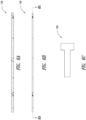
- Figure 1 shows a front elevational view of a top-hanging sliding door 100 which includes a door frame 102 that supports a sliding door panel or leaf 104.
- the door panel 104 is movable between a closed position (as shown) wherein the door panel covers an opening in a wall 106 and an open position wherein the door panel is moved to the left to expose the door opening in the wall.
- the top-hanging sliding door 100 may be configured to open to the right (“right opening” or "right handed") rather than open to the left (“left opening” or “left handed”).
- the door panel 104 includes a leading edge 108 and a trailing edge 110 opposite the leading edge.
- the door panel 104 maybe top-hanging from a track disposed in a top portion 112 of the door frame 102 with no exposed floor track at a bottom 114 of the door panel, such that there is an air gap between the bottom 114 of the door panel and a floor surface below the bottom of the door panel.
- the bottom 114 of the door panel 104 includes a downward facing opening 116 (see Figure 9 ) which receives a drop seal assembly that includes a seal which automatically drops downward to the floor surface when the door panel is moved into the closed position.
- Figures 2-6C show various views of a drop seal assembly 118 which may be fixedly positioned within the downward facing opening 116 of the door panel 104.
- the drop seal assembly 118 includes an elongated E-channel extrusion 120 which includes a seal channel 122 (see Figure 4C ) and a sill guide channel 124.
- the E-channel extrusion 120 may be positioned within the downward facing opening 116 in the bottom 114 of the door panel 104.
- the drop seal assembly 118 also includes an elongated guide bar 126 that is fixedly coupled to the E-channel extrusion 118 using a plurality of screws 128.
- the drop seal assembly 118 further includes an elongated carriage extrusion 130 which has a seal 132 ( Figure 9 ) attached to bottom side 134 ( Figure 5D ) of the carriage extrusion, and an upward facing channel 136 to receive the guide bar 126 therein.
- the guide bar 126 includes a centrally located angled glide slot 138 therein which receives a pin 140 which passes through the upward facing channel 136 when the guide bar 126 is disposed within the upward facing channel of the carriage extrusion 130.
- the glide slot 138 may be at any suitable angle, such as 45 degrees, 30 degrees, etc.
- the pin 140 rides in the guide slot 138 such that when a horizontal force is applied to the carriage extrusion 130, the horizontal force is partially transformed into a vertical force which causes the carriage extrusion to move vertically relative to the vertically fixed components (e.g ., the guide bar 126, the E-channel extrusion 120, the door panel 104). As discussed further below, this action causes the seal 132 to automatically move from a raised position wherein the seal is spaced apart from the floor surface to a lowered position wherein the seal is in contact with the floor surface.
- the vertically fixed components e.g ., the guide bar 126, the E-channel extrusion 120, the door panel 104.
- a wheel bearing 142 may be fixedly attached to the carriage extrusion 130 proximate the trailing edge 144 thereof.
- the wheel bearing 142 may be held in place by a screw 146 and a standoff 148, for example.
- the wheel bearing 142 extends outward from the carriage extrusion 130 and is substantially aligned with the sill guide channel 124 of the E-channel extrusion 120 to interact with an adjustable sill guide, as discussed below.
- the carriage extrusion 130 may also be coupled to the guide bar 126 via one or more springs 150, which springs bias the carriage extrusion 130 in the raised position to prevent the seal 132 from contacting the floor surface when the door panel 104 is in the open position.
- springs 150 bias the carriage extrusion 130 in the raised position to prevent the seal 132 from contacting the floor surface when the door panel 104 is in the open position.
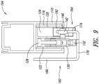
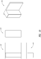
- FIGS 7A-7C show various views of an adjustable sill guide 160 which operates as a drop seal assembly activator.
- the adjustable sill guide 160 includes a metal bracket 162 and an adjustable bumper or bushing 164.
- the metal bracket 162 includes a first vertical portion 166 which includes four holes 168 therein that receive respective screws (not shown) to allow the metal bracket to be secured to the door frame 102 proximate the trailing edge 110 of the door panel 104 when the door panel is in the closed position.
- the metal bracket 162 also includes a horizontal portion 170 extending outward from the first vertical portion 166 which includes a countersink hole 172 which receives a screw to fasten the metal bracket to the flooring.
- the metal bracket 162 also includes a second vertical portion 174 that extends upward from an outermost portion of the horizontal portion 170.
- the second vertical portion 174 supports the adjustable bumper 164 and includes a smooth elongated slot 176 and a slot 178 with four detent locations on an upper surface thereof.
- a pin 180 detents into one of the four detent locations in the slot 178.
- a spring 182 maintained by a pin 184 which provides a rotational axis for the bumper 164, imparts an upward force on the bumper to maintain the pin 182 in one of the four detent locations of the slot 178.
- the spring 182 is compressed between an inner downward facing surface 186 ( Figure 7B ) of the bumper 164 and a top surface 188 ( Figure 7A ) of the second vertical portion 174 of the metal bracket 162.
- the bumper 164 includes an adjustment slot 190 at the bottom thereof (e.g., at least partially below the bottom 114 of the door panel 104) which receives a screwdriver or other tool to allow the user to rotate the bumper downward about the pin 184, which disengages the pin 180 out of the detent locations of the slot 178 and allows the user to slide the bumper 164 horizontally back and forth.
- the spring 182 imparts the upward rotational force on the bumper 164 to automatically maintain the pin 180 in one of the four detent locations of the slot 178.
- the horizontal location of the bumper 164 may be selectively adjusted.
- the bumper 164 may be moved toward the latch jamb of the door frame 102 such that the bearing 142 contacts the bearing surface 192 of the bumper 164 later when the door panel 104 is closed to reduce the drop distance.
- the bumper 164 may be moved away from the latch jamb of the door frame 102 such that the bearing 142 contacts the bearing surface 192 earlier when the door panel 104 is closed to increase the drop distance, thereby accommodating installations which have varying air gaps between the bottom 110 of the door panel 104 and the floor surface.
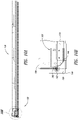
- FIG 8 shows an implementation for an adjustable sill guide 200 which may be used for a door panel which opens to the right.
- the adjustable sill guide 200 is substantially similar to the adjustable sill guide 164, so a detailed discussion of the sill guide 200 is not required.
- FIGS 11-15B show various views of a drop seal assembly 210 which utilizes a magnetic drop seal activator.
- the drop seal assembly 210 is similar in many aspects to the drop seal assembly 118 discussed above, so only differences between the drop seal assembly 210 and the drop seal assembly 118 are discussed herein for the sake of brevity.
- opposing magnets are used to drive the carriage extrusion 130 downward from the raised position to the lowered position.
- a first magnet bracket 212 which supports a first magnet 214 is coupled to the leading end 144 of the carriage extrusion 130 via screws 216.
- a second magnet bracket 218 which supports a second magnet 220 is coupled to the door frame 102 (e.g., stile pocket) at a position that is horizontally aligned with the first magnet 214 (see Figures 15A-15B ).
- the first magnet 214 and the second magnet 220 are oriented such that the same poles face each other (i.e., North pole facing North pole, or South pole facing South pole), which causes a repelling force between the first magnet 214 and the second magnet 220 when the first magnet is brought into proximity of the second magnet as the door panel 104 is moved from the open position into the closed position.
- the carriage extrusion 130 is pushed backwards using the repelling force between the first magnet 214 and the second magnet 220 to cause the carriage extrusion to move as described above from the raised position to the lowered position.
- the magnetic drop seal activator implementation is that the system is self-adjusting.
- the air gap between the first and second magnets 214 and 220 allows for variation in distances between the bottom 110 of the door panel 104 and the floor surface.
- the force between the first magnet 214 and the second magnet 220 when the door panel 104 is in the closed position is strong enough to drive the carriage extrusion 130 downward such that the seal 132 compresses against the floor surface, but the force is not so strong so as to prevent the door panel 104 from shutting and/or remaining in the closed position.
- the magnetic force between the first and second magnets 214 and 220 drives the carriage extrusion 130 downward to the lower floor surface for a range of distances between the bottom 110 of the door panel 104 and the floor surface.
- a fixed or non-adjustable sill guide may be positioned in the still guide channel 124 of the E-channel extrusion 120 to prevent the bottom 110 of the door panel 104 from swinging outward from the door frame 102 and wall 106.
- the same fixed sill guide may be used in installations which do not include a drop seal assembly.
- another advantage of the magnetic drop seal activator implementation is that the same fixed sill guide may be used for all types of installations including those which include a drop seal assembly and those which do not include a drop seal assembly.
Landscapes
- Engineering & Computer Science (AREA)
- Civil Engineering (AREA)
- Structural Engineering (AREA)
- Mechanical Engineering (AREA)
- Specific Sealing Or Ventilating Devices For Doors And Windows (AREA)
- Wing Frames And Configurations (AREA)
Applications Claiming Priority (3)
| Application Number | Priority Date | Filing Date | Title |
|---|---|---|---|
| US201762442623P | 2017-01-05 | 2017-01-05 | |
| EP17889625.4A EP3545156B1 (fr) | 2017-01-05 | 2017-12-20 | Système d'étanchéité de porte pour une porte coulissante suspendue par le haut |
| PCT/US2017/067690 WO2018128824A1 (fr) | 2017-01-05 | 2017-12-20 | Porte coulissante suspendue comprenant un guide inférieur et un joint |
Related Parent Applications (1)
| Application Number | Title | Priority Date | Filing Date |
|---|---|---|---|
| EP17889625.4A Division EP3545156B1 (fr) | 2017-01-05 | 2017-12-20 | Système d'étanchéité de porte pour une porte coulissante suspendue par le haut |
Publications (1)
| Publication Number | Publication Date |
|---|---|
| EP4151823A1 true EP4151823A1 (fr) | 2023-03-22 |
Family
ID=62791409
Family Applications (2)
| Application Number | Title | Priority Date | Filing Date |
|---|---|---|---|
| EP17889625.4A Active EP3545156B1 (fr) | 2017-01-05 | 2017-12-20 | Système d'étanchéité de porte pour une porte coulissante suspendue par le haut |
| EP22205923.0A Pending EP4151823A1 (fr) | 2017-01-05 | 2017-12-20 | Système d'étanchéité de porte pour une porte coulissante suspendue par le dessus |
Family Applications Before (1)
| Application Number | Title | Priority Date | Filing Date |
|---|---|---|---|
| EP17889625.4A Active EP3545156B1 (fr) | 2017-01-05 | 2017-12-20 | Système d'étanchéité de porte pour une porte coulissante suspendue par le haut |
Country Status (5)
| Country | Link |
|---|---|
| US (2) | US11274490B2 (fr) |
| EP (2) | EP3545156B1 (fr) |
| CA (1) | CA3048900A1 (fr) |
| ES (1) | ES2936413T3 (fr) |
| WO (1) | WO2018128824A1 (fr) |
Families Citing this family (9)
| Publication number | Priority date | Publication date | Assignee | Title |
|---|---|---|---|---|
| WO2017190779A1 (fr) * | 2016-05-04 | 2017-11-09 | Planet Gdz Ag | Dispositif d'étanchéité |
| US11585151B2 (en) * | 2018-02-19 | 2023-02-21 | Tucson Rolling Shutters, Inc. | Self-adjusting bottom bar for a retractable screen |
| US11118385B2 (en) * | 2018-04-09 | 2021-09-14 | ASSA ABLOY Accessories and Door Controls Group, Inc. | Integrated guide system and door seal for a soft close sliding door |
| CN209469329U (zh) * | 2018-08-20 | 2019-10-08 | 深圳市大疆创新科技有限公司 | 门底密封装置及门 |
| IT201900003599A1 (it) * | 2019-03-12 | 2020-09-12 | Comaglio S R L | Dispositivo parafreddo, in particolare per porte o finestre ad anta scorrevole |
| US20200355004A1 (en) * | 2019-05-06 | 2020-11-12 | Schlage Lock Company Llc | Sliding door systems |
| IT201900018683A1 (it) | 2019-10-14 | 2021-04-14 | Unifor Spa | Porta con guarnizione magnetica |
| CN111608542A (zh) * | 2020-04-22 | 2020-09-01 | 滁州市银达门窗有限公司 | 一种平移推拉式隔音窗及生产方法 |
| US11761262B2 (en) * | 2021-05-03 | 2023-09-19 | National Guard Products, Inc. | Method, system and apparatus for controlling excessive gaps of a door bottom |
Citations (4)
| Publication number | Priority date | Publication date | Assignee | Title |
|---|---|---|---|---|
| FR1238196A (fr) * | 1958-11-22 | 1960-08-05 | Bourrelet d'étanchéité pour portes | |
| EP2476857A2 (fr) | 2011-01-14 | 2012-07-18 | GEZE GmbH | Installation de porte coulissante avec joint descendant |
| CH704410A1 (de) | 2011-01-31 | 2012-07-31 | Planet Gdz Ag | Absenkdichtungsvorrichtung. |
| CN204252788U (zh) * | 2014-11-10 | 2015-04-08 | 北京凯必盛自动门技术有限公司 | 一种平滑门密封机构 |
Family Cites Families (34)
| Publication number | Priority date | Publication date | Assignee | Title |
|---|---|---|---|---|
| GB191108476A (en) * | 1911-04-05 | 1912-04-04 | Harry Aves | Improved Draught and Weather Excluder for Doors and Windows. |
| US1489734A (en) * | 1923-09-17 | 1924-04-08 | Louis F Brasch | Door hanger |
| US2035723A (en) * | 1935-01-15 | 1936-03-31 | James K Robinson | Automatic weather strip and silencer |
| DE800020C (de) * | 1948-10-02 | 1950-08-04 | Ernst Martens | Vorrichtung zum Abdichten der unteren Tuerfuge |
| US3604152A (en) * | 1969-10-20 | 1971-09-14 | Ever Roll Mfg Corp | Magnetic threshold construction |
| DE2627564A1 (de) * | 1976-06-19 | 1977-12-22 | Saeger Geb Schmitz Else | Abdichtungsvorrichtung fuer tueren |
| EP0221207A1 (fr) * | 1985-09-30 | 1987-05-13 | Derek Smith | Mécanisme d'étanchéité de porte |
| ES1002297Y (es) * | 1987-03-20 | 1990-02-16 | Berniola Gil Antonio | Nuevo burlete para el extremo inferior de las puertas y similares |
| DE4014106C2 (de) * | 1990-05-02 | 1995-05-18 | Hoermann Kg Freisen | Bodendichtungsleiste für eine Drehflügeltür |
| US5454192A (en) * | 1993-06-25 | 1995-10-03 | Richard S. Adler | Automatic door sweep |
| JPH07317457A (ja) * | 1994-05-26 | 1995-12-05 | Toppan Printing Co Ltd | 吊り戸下部隙間閉塞装置 |
| US6108989A (en) * | 1995-10-17 | 2000-08-29 | Dorma Gmbh & Co. Kg | Wall partition system and a device for securing a wall partition system |
| JPH10280827A (ja) * | 1997-04-04 | 1998-10-20 | Nakao Seisakusho:Kk | 引き戸の隙間閉塞装置 |
| JPH10331547A (ja) * | 1997-05-29 | 1998-12-15 | Mitsuteru Saito | 扉の仕切り装置 |
| US20040010973A1 (en) * | 2002-07-22 | 2004-01-22 | Tk Canada Limited | Automatic door sweep |
| DE502004012297D1 (de) * | 2003-01-28 | 2011-04-28 | Planet Gdz Ag | Absenkbare Türdichtung einer Schiebetür |
| JP2005009278A (ja) * | 2003-06-19 | 2005-01-13 | Mori Homes:Kk | 建具 |
| EP1717405A1 (fr) * | 2005-04-29 | 2006-11-02 | Ernst Keller GmbH & Co. KG | Dispositif d'étanchéité pour porte |
| EP2088277B1 (fr) * | 2008-02-08 | 2015-12-23 | Planet GDZ AG | Agencement d'étanchéité pour une porte sans seuil |
| JP2010180527A (ja) * | 2009-01-09 | 2010-08-19 | Meiko:Kk | 引戸の隙間封鎖装置 |
| DE102010030710B4 (de) * | 2010-06-30 | 2024-02-29 | Geze Gmbh | Türanlage |
| DK2770890T3 (en) * | 2011-10-24 | 2019-04-08 | Laurence C R Co Inc | Sliding Panel Event |
| KR101459229B1 (ko) * | 2013-05-15 | 2014-11-11 | 한국철도기술연구원 | 전동차 도어 구조 |
| IL234556B (en) * | 2014-09-09 | 2019-07-31 | Gregory Orenbach | A watertight door with a portable lock |
| WO2016066577A2 (fr) * | 2014-10-27 | 2016-05-06 | Planet Gdz Ag | Dispositif d'étanchéité |
| DE102015000197A1 (de) * | 2015-01-15 | 2016-07-21 | Buchele Gmbh | Sicherheitstürblatt |
| DE102015118174A1 (de) * | 2015-10-23 | 2017-04-27 | Huga Hubert Gaisendrees KG | Dichtungsvorrichtung für eine Schiebetür sowie damit versehene Schiebetür |
| US10024100B2 (en) * | 2016-04-26 | 2018-07-17 | Cmech (Guangzhou) Ltd. | Magnetically actuated door seal |
| WO2017190779A1 (fr) * | 2016-05-04 | 2017-11-09 | Planet Gdz Ag | Dispositif d'étanchéité |
| WO2017191273A1 (fr) * | 2016-05-04 | 2017-11-09 | Planet Gdz Ag | Dispositif d'étanchéification pour une porte coulissante |
| FR3052180B1 (fr) * | 2016-06-01 | 2019-05-03 | Sarl Portes Ellipse | Porte comportant un joint de bas de porte |
| DE102016116197A1 (de) * | 2016-08-31 | 2018-03-01 | Athmer Ohg | Schiebetür |
| DE102017117573B4 (de) * | 2017-08-02 | 2021-02-11 | Huga Kg | Anordnung einer Dichtungsvorrichtung sowie damit versehene Schiebetür |
| EP3524765A1 (fr) * | 2018-02-13 | 2019-08-14 | Planet GDZ AG | Protection anti-effraction abaissable |
-
2017
- 2017-12-20 CA CA3048900A patent/CA3048900A1/fr active Pending
- 2017-12-20 EP EP17889625.4A patent/EP3545156B1/fr active Active
- 2017-12-20 WO PCT/US2017/067690 patent/WO2018128824A1/fr unknown
- 2017-12-20 US US16/475,647 patent/US11274490B2/en active Active
- 2017-12-20 ES ES17889625T patent/ES2936413T3/es active Active
- 2017-12-20 EP EP22205923.0A patent/EP4151823A1/fr active Pending
-
2022
- 2022-03-11 US US17/693,147 patent/US20220372816A1/en active Pending
Patent Citations (4)
| Publication number | Priority date | Publication date | Assignee | Title |
|---|---|---|---|---|
| FR1238196A (fr) * | 1958-11-22 | 1960-08-05 | Bourrelet d'étanchéité pour portes | |
| EP2476857A2 (fr) | 2011-01-14 | 2012-07-18 | GEZE GmbH | Installation de porte coulissante avec joint descendant |
| CH704410A1 (de) | 2011-01-31 | 2012-07-31 | Planet Gdz Ag | Absenkdichtungsvorrichtung. |
| CN204252788U (zh) * | 2014-11-10 | 2015-04-08 | 北京凯必盛自动门技术有限公司 | 一种平滑门密封机构 |
Also Published As
| Publication number | Publication date |
|---|---|
| EP3545156A1 (fr) | 2019-10-02 |
| EP3545156A4 (fr) | 2020-08-12 |
| US20190368266A1 (en) | 2019-12-05 |
| US11274490B2 (en) | 2022-03-15 |
| CA3048900A1 (fr) | 2018-07-12 |
| ES2936413T3 (es) | 2023-03-16 |
| US20220372816A1 (en) | 2022-11-24 |
| EP3545156B1 (fr) | 2022-11-09 |
| WO2018128824A1 (fr) | 2018-07-12 |
Similar Documents
| Publication | Publication Date | Title |
|---|---|---|
| EP3545156B1 (fr) | Système d'étanchéité de porte pour une porte coulissante suspendue par le haut | |
| US11280130B2 (en) | Top-hanging sliding door including wedge design top seal | |
| US11118385B2 (en) | Integrated guide system and door seal for a soft close sliding door | |
| CA2535213C (fr) | Porte coulissante/systeme a panneau integre | |
| KR100848204B1 (ko) | 도어의 틈새 개폐장치 | |
| BR102013017327A2 (pt) | Carril corrediço, carro e dispositivo de guia | |
| EP2305938A1 (fr) | Arrangement d'étanchéité | |
| EP2262358B1 (fr) | Porte pour animaux présentant une résistance à l'ouverture réglable | |
| US20130199737A1 (en) | Blinds-between-glass window with thermal break | |
| US11339598B2 (en) | Window vent assist mechanism for vent window assembly | |
| KR20130038459A (ko) | 창호용 호차 | |
| KR20110010934U (ko) | 슬라이딩 도어용 높낮이 조절형 로울러장치 | |
| CN212773998U (zh) | 一种具有缓冲定位器的推拉门 | |
| CN111980556B (zh) | 兼具通风及可提升隔音水气密的平面式通风门窗结构 | |
| KR20230062188A (ko) | 창호의 기밀장치 및 이를 포함한 창호 | |
| CN212562944U (zh) | 一种淋浴房移动门 | |
| US20050235568A1 (en) | Anti-rattle device for a pocket door assembly | |
| KR102304996B1 (ko) | 미닫이창용 여밈장치 | |
| US8869868B1 (en) | Door sealing mechanism | |
| US11873677B2 (en) | Fenestration system with actuatable sealing device, and related devices, systems, and methods | |
| CN221032092U (zh) | 一种门窗滑轨装置及门窗 | |
| JP2019218696A (ja) | 引戸装置 | |
| JP3892001B2 (ja) | 引戸装置における引戸吊下げ用レールの取付構造 | |
| KR200325944Y1 (ko) | 미닫이문의 롤러조립체 | |
| CA2955898A1 (fr) | Systeme de chassis amovible dote d'une fixation de retenue inclinee a ressort integre |
Legal Events
| Date | Code | Title | Description |
|---|---|---|---|
| PUAI | Public reference made under article 153(3) epc to a published international application that has entered the european phase |
Free format text: ORIGINAL CODE: 0009012 |
|
| STAA | Information on the status of an ep patent application or granted ep patent |
Free format text: STATUS: THE APPLICATION HAS BEEN PUBLISHED |
|
| AC | Divisional application: reference to earlier application |
Ref document number: 3545156 Country of ref document: EP Kind code of ref document: P |
|
| AK | Designated contracting states |
Kind code of ref document: A1 Designated state(s): AL AT BE BG CH CY CZ DE DK EE ES FI FR GB GR HR HU IE IS IT LI LT LU LV MC MK MT NL NO PL PT RO RS SE SI SK SM TR |
|
| STAA | Information on the status of an ep patent application or granted ep patent |
Free format text: STATUS: REQUEST FOR EXAMINATION WAS MADE |
|
| 17P | Request for examination filed |
Effective date: 20230920 |
|
| RBV | Designated contracting states (corrected) |
Designated state(s): AL AT BE BG CH CY CZ DE DK EE ES FI FR GB GR HR HU IE IS IT LI LT LU LV MC MK MT NL NO PL PT RO RS SE SI SK SM TR |