EP2476857A2 - Installation de porte coulissante avec joint descendant - Google Patents
Installation de porte coulissante avec joint descendant Download PDFInfo
- Publication number
- EP2476857A2 EP2476857A2 EP12150859A EP12150859A EP2476857A2 EP 2476857 A2 EP2476857 A2 EP 2476857A2 EP 12150859 A EP12150859 A EP 12150859A EP 12150859 A EP12150859 A EP 12150859A EP 2476857 A2 EP2476857 A2 EP 2476857A2
- Authority
- EP
- European Patent Office
- Prior art keywords
- door leaf
- guide
- sliding door
- sealing
- door
- Prior art date
- Legal status (The legal status is an assumption and is not a legal conclusion. Google has not performed a legal analysis and makes no representation as to the accuracy of the status listed.)
- Withdrawn
Links
Images

Classifications
-
- E—FIXED CONSTRUCTIONS
- E06—DOORS, WINDOWS, SHUTTERS, OR ROLLER BLINDS IN GENERAL; LADDERS
- E06B—FIXED OR MOVABLE CLOSURES FOR OPENINGS IN BUILDINGS, VEHICLES, FENCES OR LIKE ENCLOSURES IN GENERAL, e.g. DOORS, WINDOWS, BLINDS, GATES
- E06B3/00—Window sashes, door leaves, or like elements for closing wall or like openings; Layout of fixed or moving closures, e.g. windows in wall or like openings; Features of rigidly-mounted outer frames relating to the mounting of wing frames
- E06B3/32—Arrangements of wings characterised by the manner of movement; Arrangements of movable wings in openings; Features of wings or frames relating solely to the manner of movement of the wing
- E06B3/34—Arrangements of wings characterised by the manner of movement; Arrangements of movable wings in openings; Features of wings or frames relating solely to the manner of movement of the wing with only one kind of movement
- E06B3/42—Sliding wings; Details of frames with respect to guiding
- E06B3/46—Horizontally-sliding wings
- E06B3/4609—Horizontally-sliding wings for windows
-
- E—FIXED CONSTRUCTIONS
- E06—DOORS, WINDOWS, SHUTTERS, OR ROLLER BLINDS IN GENERAL; LADDERS
- E06B—FIXED OR MOVABLE CLOSURES FOR OPENINGS IN BUILDINGS, VEHICLES, FENCES OR LIKE ENCLOSURES IN GENERAL, e.g. DOORS, WINDOWS, BLINDS, GATES
- E06B7/00—Special arrangements or measures in connection with doors or windows
- E06B7/16—Sealing arrangements on wings or parts co-operating with the wings
- E06B7/18—Sealing arrangements on wings or parts co-operating with the wings by means of movable edgings, e.g. draught sealings additionally used for bolting, e.g. by spring force or with operating lever
- E06B7/20—Sealing arrangements on wings or parts co-operating with the wings by means of movable edgings, e.g. draught sealings additionally used for bolting, e.g. by spring force or with operating lever automatically withdrawn when the wing is opened, e.g. by means of magnetic attraction, a pin or an inclined surface, especially for sills
- E06B7/21—Sealing arrangements on wings or parts co-operating with the wings by means of movable edgings, e.g. draught sealings additionally used for bolting, e.g. by spring force or with operating lever automatically withdrawn when the wing is opened, e.g. by means of magnetic attraction, a pin or an inclined surface, especially for sills with sealing strip movable in plane of wing
-
- E—FIXED CONSTRUCTIONS
- E06—DOORS, WINDOWS, SHUTTERS, OR ROLLER BLINDS IN GENERAL; LADDERS
- E06B—FIXED OR MOVABLE CLOSURES FOR OPENINGS IN BUILDINGS, VEHICLES, FENCES OR LIKE ENCLOSURES IN GENERAL, e.g. DOORS, WINDOWS, BLINDS, GATES
- E06B7/00—Special arrangements or measures in connection with doors or windows
- E06B7/16—Sealing arrangements on wings or parts co-operating with the wings
- E06B7/18—Sealing arrangements on wings or parts co-operating with the wings by means of movable edgings, e.g. draught sealings additionally used for bolting, e.g. by spring force or with operating lever
- E06B7/20—Sealing arrangements on wings or parts co-operating with the wings by means of movable edgings, e.g. draught sealings additionally used for bolting, e.g. by spring force or with operating lever automatically withdrawn when the wing is opened, e.g. by means of magnetic attraction, a pin or an inclined surface, especially for sills
- E06B7/215—Sealing arrangements on wings or parts co-operating with the wings by means of movable edgings, e.g. draught sealings additionally used for bolting, e.g. by spring force or with operating lever automatically withdrawn when the wing is opened, e.g. by means of magnetic attraction, a pin or an inclined surface, especially for sills with sealing strip being moved to a retracted position by elastic means, e.g. springs
Definitions
- the invention relates to a sliding door system according to the preamble of patent claim 1.
- a sliding door system with at least one slidingly mounted door known.
- At least one sealing device is provided which serves to seal the door leaf with respect to at least one adjacent component of the sliding door system, wherein the sealing device has at least one movable sealing strip.
- the sealing strip is actuated depending on the position of the door leaf, that is, switched between its non-sealing and its sealing position, to which the sealing device may have at least one actuated depending on the position of the door leaf actuator.
- the door leaf also has a guide device which comprises at least one stationary and at least one wing-fixed guide element. Due to the separate juxtaposition of the guide device and the sealing device, relatively large thickness of the wing is required for receiving or mounting these devices, at least in this area.
- the invention has for its object to provide a sliding door system, claim the sealing device and guide means little space.
- the guide device has at least one guide element which serves as a stop element of the sealing device, the space requirement of these devices in or on the wing is minimized.
- the guide element may be formed integrally with the stop element.
- the guide element and the stop element are formed as separate components and connected to each other.
- At least one guide groove can be arranged, in which the guide element engages.
- other arrangements may be provided instead of a guide groove, which allow interaction of the guide element with the door leaf.
- the sealing device may have an actuating element which cooperates with a triggering device which deflects the force component of the restoring device acting in the direction of movement of the door leaf via at least one lever and / or at least one driver in a direction perpendicular to the direction of movement of the door leaf.
- the first driver of the triggering device can with the building side, i. for example, cooperate with the building floor or on a stationary component of the sliding door system mounted stop element. By selecting the mounting location of the stop element, the position of the door leaf, in which the sealing device is to be actuated, can be defined.
- the stop element may have a receiving region for the first driver, wherein the receiving region may have at least one inclined with respect to the direction of movement of the door leaf portion and at least one parallel with respect to the direction of movement of the door leaf, straight portion.
- the oblique section is preferably run through for lowering the sealing device, and in an advantageous embodiment, the first driver of the triggering device acts on when the door leaf is completely closed the parallel with respect to the direction of movement of the door leaf, straight portion of the receiving portion of the stop member, whereby the force caused by the return means of the sealing means is deflected in a direction in which it does not affect the movement of the door leaf.
- the first driver can be arranged on a sliding relative to a guide element of the triggering slide. As a result, an exact guidance of the first driver is guaranteed.
- the carriage can be acted upon by a return element relative to the guide element, which ensures that the first driver reliably reaches its basic position.
- a second driver can be arranged on the carriage, and the lever can be pivotably mounted on the guide element about an axis of rotation.
- the lever can interact directly with the second driver and with the actuating element of the sealing device.
- the two drivers are advantageously designed as rollers.
- the displacement of the actuating element and thus the lowering of the sealing strip of the sealing device can be further enhanced by the fact that the lever has a thickening in its free end region, wherein the transition to the thickening may be formed as a slope.
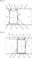
- a sliding door system 1 is shown in front view in the open position or in the closed position of the door leaf 2. Trained as a sliding leaf door 2 is slidably mounted along a fixedly arranged on a building ceiling 10 guide rail 9 via a guide device 6. The closable by the door 2 passage area of the sliding door system 1 is bounded laterally by building walls 11.
- the guide device 6 has two roller carriage 7 with rollers 8, which roll in the guide rail 9.
- the suspended on the guide device 6 door 2 has a circumferential profile 4.
- a mounted on the profile 4 handle device 5 is used for manual operation of the door leaf 2.
- a power-operated displacement of the door leaf 2 by a drive device is conceivable.
- the door leaf 2 In the area of the building floor 13, the door leaf 2 likewise has a guide device, which can serve for guiding and / or locking at the bottom, but is not shown in this view. Furthermore, the door leaf 2 in the region of the building floor 13 has a sealing device 12, which is arranged in or on a lower horizontal section of the profile 4 of the door leaf 2 and in the closed position of the door leaf 2 to seal the bottom horizontal lower edge of the door leaf 2 the building floor 13 is used.
- the sealing device 12 has for this purpose a movable sealing strip 14.
- Fig. 1a In the position according to Fig. 1a is the door leaf 2 in full open position, and accordingly, the sealing strip 14 of the sealing device 12 is in a raised position, so that between the lower edge of the sealing strip 14 and the surface of the building floor 13, a small gap remains, which unimpeded movement of the door. 2 allowed.
- Fig. 1b In the position according to Fig. 1b is the door leaf 2 in the fully closed position, and accordingly, the sealing strip 14 of the sealing device 12 is in the lowered position, so that the lower edge of the sealing strip 14 rests sealingly on the surface of the building floor 13.
- the lowering of the sealing strip 14 takes place in complete closed position of the door leaf 2 by the operation of a movable or in the door 2, in particular displaceably mounted actuating element 15, which is acted upon by a restoring device, not shown here, so that the sealing strip 14 raised at non-actuation of the actuating element 15 is or is.
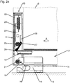
- the lower edge region of the door leaf 2 is shown in the region of its secondary closing edge 3.
- the sealing device 12 is, as in the Fig. 1 A and 1 b, arranged in or on a lower horizontal portion of the profile 4 of the door leaf 2, while in or on an adjacent vertical portion of the profile 4 in the vicinity of the minor closing edge 3 of the door leaf 2, a triggering device 20 is arranged with a guide member 23.
- a stop element 16 is mounted in the area where, with the door closed 2, its secondary closing edge 3 is located.
- the stop member 16 may, as shown here, be mounted on-the-floor. Alternatively, the stop element 16 may also be mounted in a countersunk in the building floor guide means, eg guide rail.
- the stop element 16 has a receiving region 17 for a first driver 21 of the triggering device 20, wherein the receiving region 17 is formed in this embodiment as an angled groove, i.
- the receiving region 17 is formed in this embodiment as an angled groove, i.
- a straight portion 19 connects, which is aligned at least approximately parallel to the direction of movement of the door leaf 2.
- a return element 24 designed as a tension spring in this exemplary embodiment acts on the carriage upwards, the return element 24 being articulated at one end in an upper region of the guide element 23 and at the other end on the carriage 22.
- a lever 26 is pivotally mounted about a rotation axis 27.
- the carriage 22 engages with a recess 28, the rotation axis 27, whereby the range of movement of the carriage 22 is defined by the rotation axis 27 serves as an upper stop for the carriage 22.
- the lever 26 cooperates with a second driver 25, likewise arranged on the carriage 22 and likewise embodied as a roller in this exemplary embodiment, and with the actuating element 15 of the sealing device 12.
- the interaction of the driver 25 with the lever 26 is characterized by minimal friction, so that an optimal transmission of the forces is ensured.
- first driver 21 of the triggering device 20 has moved according to the movement of the door leaf 2 from the left to the stop element 16 and is already close to the oblique portion 18 of the receiving portion 17 of the stop element 16.
- first driver 21 Upon further movement of the door leaf 2 in the closing direction (arrow A) comes the first driver 21 then in contact with the inclined portion 18 of the receiving portion 17 of the stopper member 16 and rolls down along this, whereby the carriage 22 of the triggering device 20 is pulled against the force of the return element 24 downward.
- the lever 26 of the triggering device 20 is pivoted by the second driver 25 in the counterclockwise direction and thereby displaces the actuating element 15 of the sealing device 12 in the sense of lowering the sealing strip 14 against the force of the restoring device of the sealing device 12.
- Fig. 2b In the position according to Fig. 2b is the door 2 in its full closed position.
- the first driver 21 of the triggering device 20 has come from the inclined portion 18 of the receiving portion 17 of the stopper member 16 in the straight portion 19 of the receiving portion 17, so that the vertical component of movement of the driver 21 has become zero.
- the straight section 19 also compensates for assembly inaccuracies, for example, of the stop element 16, since there is no further adjustment of the sealing device 12 along the straight section 19.
- the lever 26 of the triggering device 20 has been pivoted by the second driver 25 in a completely vertical position, which in turn the actuator 15 of the sealing device 12 is displaced in the sense of lowering the sealing strip 14.
- the displacement of the actuating element 15 and thus the lowering of the sealing strip 14 of the sealing device 12 is further enhanced by the fact that the lever 26 has a thickening in its free end region, wherein the transition to the thickening formed as a slope can be.
- the actuating element 15 of the sealing device 12 is acted upon by the restoring device in the drawing to the left.
- the first driver 21 is in the straight portion 19 of the receiving portion 17 of the stopper member 16, an upward movement of the carriage 22, which by the restoring device the sealing device 12 would be effected via the lever 26 and the second driver 25, prevented, so that the door leaves 2 remains in its closed position without the use of further blocking devices.
- the triggering device 20 may alternatively or additionally be arranged at other suitable locations of the door leaf 2, for example in the region of the main closing edge of the door leaf 2 and / or in the upper region of the door leaf 2, in which case the stationary stop element 16 is mounted in this corresponding arrangement, for example in the region of the guide rail.
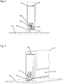
- the 3 and 4 show a front or oblique view of the lower portion of the door leaf 2.
- the door 2 has a guide groove 29, in which a mounted on the stop member 16 guide shoe 30 engages.
- the width of the guide shoe 30 is slightly smaller than the width of the guide, so that the door 2 is guided without jamming, but without significant side play.
- the guide shoe 30 may alternatively be formed integrally with the stopper member 16, wherein the stopper member 16 may then advantageously have on its co-operating with the guide groove 29 surfaces a reibwertvermindernde coating.
Landscapes
- Engineering & Computer Science (AREA)
- Civil Engineering (AREA)
- Structural Engineering (AREA)
- Specific Sealing Or Ventilating Devices For Doors And Windows (AREA)
Applications Claiming Priority (1)
| Application Number | Priority Date | Filing Date | Title |
|---|---|---|---|
| DE102011002704A DE102011002704A1 (de) | 2011-01-14 | 2011-01-14 | Schiebetüranlage |
Publications (2)
| Publication Number | Publication Date |
|---|---|
| EP2476857A2 true EP2476857A2 (fr) | 2012-07-18 |
| EP2476857A3 EP2476857A3 (fr) | 2014-08-27 |
Family
ID=45531191
Family Applications (1)
| Application Number | Title | Priority Date | Filing Date |
|---|---|---|---|
| EP12150859.2A Withdrawn EP2476857A3 (fr) | 2011-01-14 | 2012-01-12 | Installation de porte coulissante avec joint descendant |
Country Status (2)
| Country | Link |
|---|---|
| EP (1) | EP2476857A3 (fr) |
| DE (1) | DE102011002704A1 (fr) |
Cited By (6)
| Publication number | Priority date | Publication date | Assignee | Title |
|---|---|---|---|---|
| CN105003168A (zh) * | 2013-04-25 | 2015-10-28 | 李德云 | 车用平齐式推拉窗用滑动机构、推拉窗及其工作方法 |
| WO2017068173A1 (fr) * | 2015-10-23 | 2017-04-27 | Planet Gdz Ag | Unité d'étanchéité pour porte coulissante |
| WO2017190779A1 (fr) | 2016-05-04 | 2017-11-09 | Planet Gdz Ag | Dispositif d'étanchéité |
| WO2017191273A1 (fr) | 2016-05-04 | 2017-11-09 | Planet Gdz Ag | Dispositif d'étanchéification pour une porte coulissante |
| WO2018128824A1 (fr) | 2017-01-05 | 2018-07-12 | Aurora Systems Inc. | Porte coulissante suspendue comprenant un guide inférieur et un joint |
| EP3524765A1 (fr) * | 2018-02-13 | 2019-08-14 | Planet GDZ AG | Protection anti-effraction abaissable |
Citations (1)
| Publication number | Priority date | Publication date | Assignee | Title |
|---|---|---|---|---|
| EP1447514A2 (fr) | 2003-01-28 | 2004-08-18 | Planet GDZ AG | Joint d'étanchéité abaissable d'une porte coulissante |
Family Cites Families (2)
| Publication number | Priority date | Publication date | Assignee | Title |
|---|---|---|---|---|
| US4819378A (en) * | 1984-11-27 | 1989-04-11 | Kazuaki Ando | Self-closing door sealing structure |
| JP5250557B2 (ja) * | 2007-10-09 | 2013-07-31 | ナブテスコ株式会社 | 気密扉 |
-
2011
- 2011-01-14 DE DE102011002704A patent/DE102011002704A1/de not_active Withdrawn
-
2012
- 2012-01-12 EP EP12150859.2A patent/EP2476857A3/fr not_active Withdrawn
Patent Citations (1)
| Publication number | Priority date | Publication date | Assignee | Title |
|---|---|---|---|---|
| EP1447514A2 (fr) | 2003-01-28 | 2004-08-18 | Planet GDZ AG | Joint d'étanchéité abaissable d'une porte coulissante |
Cited By (21)
| Publication number | Priority date | Publication date | Assignee | Title |
|---|---|---|---|---|
| CN105003168B (zh) * | 2013-04-25 | 2017-03-15 | 李德云 | 车用平齐式推拉窗用滑动机构、推拉窗及其工作方法 |
| CN105003168A (zh) * | 2013-04-25 | 2015-10-28 | 李德云 | 车用平齐式推拉窗用滑动机构、推拉窗及其工作方法 |
| CN108138536A (zh) * | 2015-10-23 | 2018-06-08 | 普兰特Gdz股份公司 | 用于滑动门的密封单元 |
| WO2017068173A1 (fr) * | 2015-10-23 | 2017-04-27 | Planet Gdz Ag | Unité d'étanchéité pour porte coulissante |
| AU2016341396B2 (en) * | 2015-10-23 | 2020-01-16 | Planet Gdz Ag | Sealing unit for a sliding door |
| WO2017067539A3 (fr) * | 2015-10-23 | 2018-05-31 | Huga Hubert Gaisendrees KG | Système d'étanchéité pour porte coulissante et porte coulissante munie dudit système |
| AU2017260678C1 (en) * | 2016-05-04 | 2020-02-20 | Planet Gdz Ag | Sealing device for a sliding door |
| AU2016405471C1 (en) * | 2016-05-04 | 2020-05-07 | Planet Gdz Ag | Sealing device |
| CN109072665A (zh) * | 2016-05-04 | 2018-12-21 | 普兰特Gdz股份公司 | 用于滑动门的密封设备 |
| CN109154178A (zh) * | 2016-05-04 | 2019-01-04 | 普兰特Gdz股份公司 | 密封设备 |
| US11118395B2 (en) | 2016-05-04 | 2021-09-14 | Assa Abloy (Schweiz) Ag | Sealing device |
| WO2017190779A1 (fr) | 2016-05-04 | 2017-11-09 | Planet Gdz Ag | Dispositif d'étanchéité |
| WO2017191273A1 (fr) | 2016-05-04 | 2017-11-09 | Planet Gdz Ag | Dispositif d'étanchéification pour une porte coulissante |
| AU2017260678B2 (en) * | 2016-05-04 | 2020-01-23 | Planet Gdz Ag | Sealing device for a sliding door |
| AU2016405471B2 (en) * | 2016-05-04 | 2020-02-06 | Planet Gdz Ag | Sealing device |
| WO2018128824A1 (fr) | 2017-01-05 | 2018-07-12 | Aurora Systems Inc. | Porte coulissante suspendue comprenant un guide inférieur et un joint |
| EP3545156A4 (fr) * | 2017-01-05 | 2020-08-12 | Aurora Systems Inc. | Porte coulissante suspendue comprenant un guide inférieur et un joint |
| US11274490B2 (en) | 2017-01-05 | 2022-03-15 | Ad Solutions, Inc. | Top-hanging sliding door including bottom guide and seal |
| EP4151823A1 (fr) | 2017-01-05 | 2023-03-22 | AD Solutions, Inc. | Système d'étanchéité de porte pour une porte coulissante suspendue par le dessus |
| WO2019158439A1 (fr) * | 2018-02-13 | 2019-08-22 | Planet Gdz Ag | Dispositif anti-effraction abaissable |
| EP3524765A1 (fr) * | 2018-02-13 | 2019-08-14 | Planet GDZ AG | Protection anti-effraction abaissable |
Also Published As
| Publication number | Publication date |
|---|---|
| EP2476857A3 (fr) | 2014-08-27 |
| DE102011002704A1 (de) | 2012-07-19 |
Similar Documents
| Publication | Publication Date | Title |
|---|---|---|
| DE19547049C2 (de) | Auszugsperre für übereinander angeordnete Schubladen | |
| EP2476856B1 (fr) | Installation de porte coulissante | |
| EP2829679B1 (fr) | Ferrure pour l'appui d'un battant mobile contre une bordure fixe | |
| EP2476857A2 (fr) | Installation de porte coulissante avec joint descendant | |
| DE102017117573B4 (de) | Anordnung einer Dichtungsvorrichtung sowie damit versehene Schiebetür | |
| AT511249B1 (de) | Schiebetür für ein fahrzeug | |
| DE102015000197A1 (de) | Sicherheitstürblatt | |
| AT504314B1 (de) | Vorrichtung zur regelung der öffnungsfolge von zweiflügeligen schwenktüren | |
| EP2402546A2 (fr) | Installation de porte | |
| EP2402545B1 (fr) | Installation de porte coulissante | |
| EP2427617A1 (fr) | Ferrure | |
| EP2703591A2 (fr) | Dispositif d'étanchéité pour fenêtres ou portes coulissantes | |
| DE102012213786B3 (de) | Verlagerungsanordnung zur Verlagerung eines Flügels eines Fensters, einer Tür oder dergleichen relativ zu einer festen Einfassung | |
| EP2527575B1 (fr) | Ferrure de porte coulissante | |
| EP3371402B1 (fr) | Agencement de ferrure pour élément à soulèvement et coulissement avec elément de réglage monté sur cadre | |
| DE9315127U1 (de) | Fenster mit einem in vertikaler Richtung verschiebbaren Fensterflügel | |
| EP3511493B1 (fr) | Système de porte coulissante | |
| DE102012210594A1 (de) | Schiebetüranlage | |
| EP2402542B1 (fr) | Installation de porte | |
| DE10300302A1 (de) | Sektionaltor mit verschiebbarer Führungsschiene | |
| DE19650809A1 (de) | Vorrichtung zur Regelung der Schließfolge von zweiflügeligen Türen | |
| DE102010030785B4 (de) | Schiebetüranlage | |
| DE2341202C3 (de) | Fenster | |
| DE102012213782B4 (de) | Verlagerungsanordnung zur Verlagerung eines Schiebeflügels eines Fensters, einer Tür oder dergleichen relativ zu einer festen Einfassung mit einem flügelseitigen und einem einfassungsseitigen Steuerelement | |
| EP2685040A2 (fr) | Composant précontraint et procédé de fonctionnement pour une fenêtre ou une porte-fenêtre |
Legal Events
| Date | Code | Title | Description |
|---|---|---|---|
| PUAI | Public reference made under article 153(3) epc to a published international application that has entered the european phase |
Free format text: ORIGINAL CODE: 0009012 |
|
| AK | Designated contracting states |
Kind code of ref document: A2 Designated state(s): AL AT BE BG CH CY CZ DE DK EE ES FI FR GB GR HR HU IE IS IT LI LT LU LV MC MK MT NL NO PL PT RO RS SE SI SK SM TR |
|
| AX | Request for extension of the european patent |
Extension state: BA ME |
|
| PUAL | Search report despatched |
Free format text: ORIGINAL CODE: 0009013 |
|
| AK | Designated contracting states |
Kind code of ref document: A3 Designated state(s): AL AT BE BG CH CY CZ DE DK EE ES FI FR GB GR HR HU IE IS IT LI LT LU LV MC MK MT NL NO PL PT RO RS SE SI SK SM TR |
|
| AX | Request for extension of the european patent |
Extension state: BA ME |
|
| RIC1 | Information provided on ipc code assigned before grant |
Ipc: E06B 7/215 20060101AFI20140724BHEP Ipc: E06B 3/46 20060101ALI20140724BHEP |
|
| 17P | Request for examination filed |
Effective date: 20150223 |
|
| RBV | Designated contracting states (corrected) |
Designated state(s): AL AT BE BG CH CY CZ DE DK EE ES FI FR GB GR HR HU IE IS IT LI LT LU LV MC MK MT NL NO PL PT RO RS SE SI SK SM TR |
|
| 17Q | First examination report despatched |
Effective date: 20170811 |
|
| STAA | Information on the status of an ep patent application or granted ep patent |
Free format text: STATUS: THE APPLICATION HAS BEEN WITHDRAWN |
|
| 18W | Application withdrawn |
Effective date: 20171212 |