EP2476857A2 - Sliding door assembly with movable sealing - Google Patents
Sliding door assembly with movable sealing Download PDFInfo
- Publication number
- EP2476857A2 EP2476857A2 EP12150859A EP12150859A EP2476857A2 EP 2476857 A2 EP2476857 A2 EP 2476857A2 EP 12150859 A EP12150859 A EP 12150859A EP 12150859 A EP12150859 A EP 12150859A EP 2476857 A2 EP2476857 A2 EP 2476857A2
- Authority
- EP
- European Patent Office
- Prior art keywords
- door leaf
- guide
- sliding door
- sealing
- door
- Prior art date
- Legal status (The legal status is an assumption and is not a legal conclusion. Google has not performed a legal analysis and makes no representation as to the accuracy of the status listed.)
- Withdrawn
Links
Images

Classifications
-
- E—FIXED CONSTRUCTIONS
- E06—DOORS, WINDOWS, SHUTTERS, OR ROLLER BLINDS IN GENERAL; LADDERS
- E06B—FIXED OR MOVABLE CLOSURES FOR OPENINGS IN BUILDINGS, VEHICLES, FENCES OR LIKE ENCLOSURES IN GENERAL, e.g. DOORS, WINDOWS, BLINDS, GATES
- E06B3/00—Window sashes, door leaves, or like elements for closing wall or like openings; Layout of fixed or moving closures, e.g. windows in wall or like openings; Features of rigidly-mounted outer frames relating to the mounting of wing frames
- E06B3/32—Arrangements of wings characterised by the manner of movement; Arrangements of movable wings in openings; Features of wings or frames relating solely to the manner of movement of the wing
- E06B3/34—Arrangements of wings characterised by the manner of movement; Arrangements of movable wings in openings; Features of wings or frames relating solely to the manner of movement of the wing with only one kind of movement
- E06B3/42—Sliding wings; Details of frames with respect to guiding
- E06B3/46—Horizontally-sliding wings
- E06B3/4609—Horizontally-sliding wings for windows
-
- E—FIXED CONSTRUCTIONS
- E06—DOORS, WINDOWS, SHUTTERS, OR ROLLER BLINDS IN GENERAL; LADDERS
- E06B—FIXED OR MOVABLE CLOSURES FOR OPENINGS IN BUILDINGS, VEHICLES, FENCES OR LIKE ENCLOSURES IN GENERAL, e.g. DOORS, WINDOWS, BLINDS, GATES
- E06B7/00—Special arrangements or measures in connection with doors or windows
- E06B7/16—Sealing arrangements on wings or parts co-operating with the wings
- E06B7/18—Sealing arrangements on wings or parts co-operating with the wings by means of movable edgings, e.g. draught sealings additionally used for bolting, e.g. by spring force or with operating lever
- E06B7/20—Sealing arrangements on wings or parts co-operating with the wings by means of movable edgings, e.g. draught sealings additionally used for bolting, e.g. by spring force or with operating lever automatically withdrawn when the wing is opened, e.g. by means of magnetic attraction, a pin or an inclined surface, especially for sills
- E06B7/21—Sealing arrangements on wings or parts co-operating with the wings by means of movable edgings, e.g. draught sealings additionally used for bolting, e.g. by spring force or with operating lever automatically withdrawn when the wing is opened, e.g. by means of magnetic attraction, a pin or an inclined surface, especially for sills with sealing strip movable in plane of wing
-
- E—FIXED CONSTRUCTIONS
- E06—DOORS, WINDOWS, SHUTTERS, OR ROLLER BLINDS IN GENERAL; LADDERS
- E06B—FIXED OR MOVABLE CLOSURES FOR OPENINGS IN BUILDINGS, VEHICLES, FENCES OR LIKE ENCLOSURES IN GENERAL, e.g. DOORS, WINDOWS, BLINDS, GATES
- E06B7/00—Special arrangements or measures in connection with doors or windows
- E06B7/16—Sealing arrangements on wings or parts co-operating with the wings
- E06B7/18—Sealing arrangements on wings or parts co-operating with the wings by means of movable edgings, e.g. draught sealings additionally used for bolting, e.g. by spring force or with operating lever
- E06B7/20—Sealing arrangements on wings or parts co-operating with the wings by means of movable edgings, e.g. draught sealings additionally used for bolting, e.g. by spring force or with operating lever automatically withdrawn when the wing is opened, e.g. by means of magnetic attraction, a pin or an inclined surface, especially for sills
- E06B7/215—Sealing arrangements on wings or parts co-operating with the wings by means of movable edgings, e.g. draught sealings additionally used for bolting, e.g. by spring force or with operating lever automatically withdrawn when the wing is opened, e.g. by means of magnetic attraction, a pin or an inclined surface, especially for sills with sealing strip being moved to a retracted position by elastic means, e.g. springs
Definitions
- the invention relates to a sliding door system according to the preamble of patent claim 1.
- a sliding door system with at least one slidingly mounted door known.
- At least one sealing device is provided which serves to seal the door leaf with respect to at least one adjacent component of the sliding door system, wherein the sealing device has at least one movable sealing strip.
- the sealing strip is actuated depending on the position of the door leaf, that is, switched between its non-sealing and its sealing position, to which the sealing device may have at least one actuated depending on the position of the door leaf actuator.
- the door leaf also has a guide device which comprises at least one stationary and at least one wing-fixed guide element. Due to the separate juxtaposition of the guide device and the sealing device, relatively large thickness of the wing is required for receiving or mounting these devices, at least in this area.
- the invention has for its object to provide a sliding door system, claim the sealing device and guide means little space.
- the guide device has at least one guide element which serves as a stop element of the sealing device, the space requirement of these devices in or on the wing is minimized.
- the guide element may be formed integrally with the stop element.
- the guide element and the stop element are formed as separate components and connected to each other.
- At least one guide groove can be arranged, in which the guide element engages.
- other arrangements may be provided instead of a guide groove, which allow interaction of the guide element with the door leaf.
- the sealing device may have an actuating element which cooperates with a triggering device which deflects the force component of the restoring device acting in the direction of movement of the door leaf via at least one lever and / or at least one driver in a direction perpendicular to the direction of movement of the door leaf.
- the first driver of the triggering device can with the building side, i. for example, cooperate with the building floor or on a stationary component of the sliding door system mounted stop element. By selecting the mounting location of the stop element, the position of the door leaf, in which the sealing device is to be actuated, can be defined.
- the stop element may have a receiving region for the first driver, wherein the receiving region may have at least one inclined with respect to the direction of movement of the door leaf portion and at least one parallel with respect to the direction of movement of the door leaf, straight portion.
- the oblique section is preferably run through for lowering the sealing device, and in an advantageous embodiment, the first driver of the triggering device acts on when the door leaf is completely closed the parallel with respect to the direction of movement of the door leaf, straight portion of the receiving portion of the stop member, whereby the force caused by the return means of the sealing means is deflected in a direction in which it does not affect the movement of the door leaf.
- the first driver can be arranged on a sliding relative to a guide element of the triggering slide. As a result, an exact guidance of the first driver is guaranteed.
- the carriage can be acted upon by a return element relative to the guide element, which ensures that the first driver reliably reaches its basic position.
- a second driver can be arranged on the carriage, and the lever can be pivotably mounted on the guide element about an axis of rotation.
- the lever can interact directly with the second driver and with the actuating element of the sealing device.
- the two drivers are advantageously designed as rollers.
- the displacement of the actuating element and thus the lowering of the sealing strip of the sealing device can be further enhanced by the fact that the lever has a thickening in its free end region, wherein the transition to the thickening may be formed as a slope.
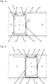
- a sliding door system 1 is shown in front view in the open position or in the closed position of the door leaf 2. Trained as a sliding leaf door 2 is slidably mounted along a fixedly arranged on a building ceiling 10 guide rail 9 via a guide device 6. The closable by the door 2 passage area of the sliding door system 1 is bounded laterally by building walls 11.
- the guide device 6 has two roller carriage 7 with rollers 8, which roll in the guide rail 9.
- the suspended on the guide device 6 door 2 has a circumferential profile 4.
- a mounted on the profile 4 handle device 5 is used for manual operation of the door leaf 2.
- a power-operated displacement of the door leaf 2 by a drive device is conceivable.
- the door leaf 2 In the area of the building floor 13, the door leaf 2 likewise has a guide device, which can serve for guiding and / or locking at the bottom, but is not shown in this view. Furthermore, the door leaf 2 in the region of the building floor 13 has a sealing device 12, which is arranged in or on a lower horizontal section of the profile 4 of the door leaf 2 and in the closed position of the door leaf 2 to seal the bottom horizontal lower edge of the door leaf 2 the building floor 13 is used.
- the sealing device 12 has for this purpose a movable sealing strip 14.
- Fig. 1a In the position according to Fig. 1a is the door leaf 2 in full open position, and accordingly, the sealing strip 14 of the sealing device 12 is in a raised position, so that between the lower edge of the sealing strip 14 and the surface of the building floor 13, a small gap remains, which unimpeded movement of the door. 2 allowed.
- Fig. 1b In the position according to Fig. 1b is the door leaf 2 in the fully closed position, and accordingly, the sealing strip 14 of the sealing device 12 is in the lowered position, so that the lower edge of the sealing strip 14 rests sealingly on the surface of the building floor 13.
- the lowering of the sealing strip 14 takes place in complete closed position of the door leaf 2 by the operation of a movable or in the door 2, in particular displaceably mounted actuating element 15, which is acted upon by a restoring device, not shown here, so that the sealing strip 14 raised at non-actuation of the actuating element 15 is or is.
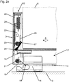
- the lower edge region of the door leaf 2 is shown in the region of its secondary closing edge 3.
- the sealing device 12 is, as in the Fig. 1 A and 1 b, arranged in or on a lower horizontal portion of the profile 4 of the door leaf 2, while in or on an adjacent vertical portion of the profile 4 in the vicinity of the minor closing edge 3 of the door leaf 2, a triggering device 20 is arranged with a guide member 23.
- a stop element 16 is mounted in the area where, with the door closed 2, its secondary closing edge 3 is located.
- the stop member 16 may, as shown here, be mounted on-the-floor. Alternatively, the stop element 16 may also be mounted in a countersunk in the building floor guide means, eg guide rail.
- the stop element 16 has a receiving region 17 for a first driver 21 of the triggering device 20, wherein the receiving region 17 is formed in this embodiment as an angled groove, i.
- the receiving region 17 is formed in this embodiment as an angled groove, i.
- a straight portion 19 connects, which is aligned at least approximately parallel to the direction of movement of the door leaf 2.
- a return element 24 designed as a tension spring in this exemplary embodiment acts on the carriage upwards, the return element 24 being articulated at one end in an upper region of the guide element 23 and at the other end on the carriage 22.
- a lever 26 is pivotally mounted about a rotation axis 27.
- the carriage 22 engages with a recess 28, the rotation axis 27, whereby the range of movement of the carriage 22 is defined by the rotation axis 27 serves as an upper stop for the carriage 22.
- the lever 26 cooperates with a second driver 25, likewise arranged on the carriage 22 and likewise embodied as a roller in this exemplary embodiment, and with the actuating element 15 of the sealing device 12.
- the interaction of the driver 25 with the lever 26 is characterized by minimal friction, so that an optimal transmission of the forces is ensured.
- first driver 21 of the triggering device 20 has moved according to the movement of the door leaf 2 from the left to the stop element 16 and is already close to the oblique portion 18 of the receiving portion 17 of the stop element 16.
- first driver 21 Upon further movement of the door leaf 2 in the closing direction (arrow A) comes the first driver 21 then in contact with the inclined portion 18 of the receiving portion 17 of the stopper member 16 and rolls down along this, whereby the carriage 22 of the triggering device 20 is pulled against the force of the return element 24 downward.
- the lever 26 of the triggering device 20 is pivoted by the second driver 25 in the counterclockwise direction and thereby displaces the actuating element 15 of the sealing device 12 in the sense of lowering the sealing strip 14 against the force of the restoring device of the sealing device 12.
- Fig. 2b In the position according to Fig. 2b is the door 2 in its full closed position.
- the first driver 21 of the triggering device 20 has come from the inclined portion 18 of the receiving portion 17 of the stopper member 16 in the straight portion 19 of the receiving portion 17, so that the vertical component of movement of the driver 21 has become zero.
- the straight section 19 also compensates for assembly inaccuracies, for example, of the stop element 16, since there is no further adjustment of the sealing device 12 along the straight section 19.
- the lever 26 of the triggering device 20 has been pivoted by the second driver 25 in a completely vertical position, which in turn the actuator 15 of the sealing device 12 is displaced in the sense of lowering the sealing strip 14.
- the displacement of the actuating element 15 and thus the lowering of the sealing strip 14 of the sealing device 12 is further enhanced by the fact that the lever 26 has a thickening in its free end region, wherein the transition to the thickening formed as a slope can be.
- the actuating element 15 of the sealing device 12 is acted upon by the restoring device in the drawing to the left.
- the first driver 21 is in the straight portion 19 of the receiving portion 17 of the stopper member 16, an upward movement of the carriage 22, which by the restoring device the sealing device 12 would be effected via the lever 26 and the second driver 25, prevented, so that the door leaves 2 remains in its closed position without the use of further blocking devices.
- the triggering device 20 may alternatively or additionally be arranged at other suitable locations of the door leaf 2, for example in the region of the main closing edge of the door leaf 2 and / or in the upper region of the door leaf 2, in which case the stationary stop element 16 is mounted in this corresponding arrangement, for example in the region of the guide rail.
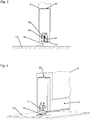
- the 3 and 4 show a front or oblique view of the lower portion of the door leaf 2.
- the door 2 has a guide groove 29, in which a mounted on the stop member 16 guide shoe 30 engages.
- the width of the guide shoe 30 is slightly smaller than the width of the guide, so that the door 2 is guided without jamming, but without significant side play.
- the guide shoe 30 may alternatively be formed integrally with the stopper member 16, wherein the stopper member 16 may then advantageously have on its co-operating with the guide groove 29 surfaces a reibwertvermindernde coating.
Landscapes
- Engineering & Computer Science (AREA)
- Civil Engineering (AREA)
- Structural Engineering (AREA)
- Specific Sealing Or Ventilating Devices For Doors And Windows (AREA)
Abstract
Description
Die Erfindung betrifft eine Schiebetüranlage nach dem Oberbegriff des Patentanspruchs 1.The invention relates to a sliding door system according to the preamble of
Aus der
Der Erfindung liegt die Aufgabe zugrunde, eine Schiebetüranlage zu schaffen, deren Dichtungseinrichtung und Führungseinrichtung wenig Bauraum beanspruchen.The invention has for its object to provide a sliding door system, claim the sealing device and guide means little space.
Die Aufgabe wird durch die Merkmale des Patentanspruchs 1 gelöst.The object is solved by the features of
Die Unteransprüche bilden vorteilhafte Ausgestaltungsmöglichkeiten der Erfindung.The subclaims form advantageous embodiments of the invention.
Dadurch, dass die Führungseinrichtung mindestens ein Führungselement aufweist, welches als Anschlagelement der Dichtungseinrichtung dient, wird der Platzbedarf dieser Einrichtungen im bzw. am Flügel minimiert.Because the guide device has at least one guide element which serves as a stop element of the sealing device, the space requirement of these devices in or on the wing is minimized.
In einer besonders vorteilhaften Ausgestaltung kann das Führungselement einstückig mit dem Anschlagelement ausgebildet sein. Alternativ ist selbstverständlich auch denkbar, dass das Führungselement und das Anschlagelement als separate Bauteile ausgebildet und miteinander verbunden sind.In a particularly advantageous embodiment, the guide element may be formed integrally with the stop element. Alternatively, of course, it is also conceivable that the guide element and the stop element are formed as separate components and connected to each other.
In einem Randbereich des Türflügels kann mindestens eine Führungsnut angeordnet sein, in welche das Führungselement eingreift. Alternativ können statt einer Führungsnut auch andere Anordnungen vorgesehen sein, welche ein Zusammenwirken des Führungselements mit dem Türflügel ermöglichen.In an edge region of the door leaf, at least one guide groove can be arranged, in which the guide element engages. Alternatively, other arrangements may be provided instead of a guide groove, which allow interaction of the guide element with the door leaf.
In einer vorteilhaften Ausgestaltung kann die Dichtungseinrichtung ein Betätigungselement aufweisen, welches mit einer Auslöseeinrichtung zusammenwirkt, welche die in Bewegungsrichtung des Türflügels wirkende Kraftkomponente der Rückstelleinrichtung über mindestens einen Hebel und/oder mindestens einen Mitnehmer in eine Richtung senkrecht zur Bewegungsrichtung des Türflügels umlenkt.In an advantageous embodiment, the sealing device may have an actuating element which cooperates with a triggering device which deflects the force component of the restoring device acting in the direction of movement of the door leaf via at least one lever and / or at least one driver in a direction perpendicular to the direction of movement of the door leaf.
Der erste Mitnehmer der Auslöseeinrichtung kann mit dem gebäudeseitig, d.h. beispielsweise am Gebäudeboden oder an einem ortsfesten Bauteil der Schiebetüranlage montierten Anschlagelement zusammenwirken. Durch die Auswahl des Montageorts des Anschlagelements lässt sich die Position des Türflügels, in welcher die Dichtungseinrichtung betätigt werden soll, definieren.The first driver of the triggering device can with the building side, i. for example, cooperate with the building floor or on a stationary component of the sliding door system mounted stop element. By selecting the mounting location of the stop element, the position of the door leaf, in which the sealing device is to be actuated, can be defined.
Das Anschlagelement kann einen Aufnahmebereich für den ersten Mitnehmer aufweisen, wobei der Aufnahmebereich mindestens einen in Bezug auf die Bewegungsrichtung des Türflügels schrägen Abschnitt sowie mindestens einen in Bezug auf die Bewegungsrichtung des Türflügels parallelen, geraden Abschnitt aufweisen kann. Der schräge Abschnitt wird bevorzugt zum Absenken der Dichtungseinrichtung durchlaufen, und in einer vorteilhaften Ausführung wirkt der erste Mitnehmer der Auslöseeinrichtung bei vollständig geschlossenem Türflügel mit dem in Bezug auf die Bewegungsrichtung des Türflügels parallelen, geraden Abschnitt des Aufnahmebereichs des Anschlagelements zusammen, wodurch die durch die Rückstelleinrichtung der Dichtungseinrichtung bewirkte Kraft in eine Richtung umgelenkt wird, in der sie die Bewegung des Türflügels nicht beeinflusst.The stop element may have a receiving region for the first driver, wherein the receiving region may have at least one inclined with respect to the direction of movement of the door leaf portion and at least one parallel with respect to the direction of movement of the door leaf, straight portion. The oblique section is preferably run through for lowering the sealing device, and in an advantageous embodiment, the first driver of the triggering device acts on when the door leaf is completely closed the parallel with respect to the direction of movement of the door leaf, straight portion of the receiving portion of the stop member, whereby the force caused by the return means of the sealing means is deflected in a direction in which it does not affect the movement of the door leaf.
Der erste Mitnehmer kann an einem gegenüber einem Führungselement der Auslöseeinrichtung verschiebbaren Schlitten angeordnet sein. Hierdurch ist eine exakte Führung des ersten Mitnehmers gewährleistet.The first driver can be arranged on a sliding relative to a guide element of the triggering slide. As a result, an exact guidance of the first driver is guaranteed.
Der Schlitten kann durch ein Rückstellelement gegenüber dem Führungselement beaufschlagt sein, wodurch sichergestellt ist, dass der erste Mitnehmer zuverlässig in seine Grundposition gelangt.The carriage can be acted upon by a return element relative to the guide element, which ensures that the first driver reliably reaches its basic position.
An dem Schlitten kann ein zweiter Mitnehmer angeordnet sein, und an dem Führungselement der Hebel um eine Drehachse schwenkbar gelagert sein. In einer bevorzugten Ausgestaltung kann der Hebel mit dem zweiten Mitnehmer sowie mit dem Betätigungselement der Dichtungseinrichtung unmittelbar zusammenwirken. Die beiden Mitnehmer sind vorteilhaft als Rollen ausgebildet.A second driver can be arranged on the carriage, and the lever can be pivotably mounted on the guide element about an axis of rotation. In a preferred embodiment, the lever can interact directly with the second driver and with the actuating element of the sealing device. The two drivers are advantageously designed as rollers.
Durch diese Anordnung wird eine optimale Übersetzung der auftretenden Kräfte erreicht, und ferner werden hierdurch Verluste, beispielsweise durch Reibung bedingt, vermieden.By this arrangement, an optimal translation of the forces occurring is achieved, and further losses, for example due to friction, avoided.
Unmittelbar vor Erreichen der vollständigen Geschlossenlage des Türflügels kann die Verlagerung des Betätigungselements und somit das Absenken der Dichtleiste der Dichtungseinrichtung noch dadurch verstärkt werden, dass der Hebel in seinem freien Endbereich eine Verdickung aufweist, wobei der Übergang zu der Verdickung als Schräge ausgebildet sein kann.Immediately before reaching the complete closed position of the door wing, the displacement of the actuating element and thus the lowering of the sealing strip of the sealing device can be further enhanced by the fact that the lever has a thickening in its free end region, wherein the transition to the thickening may be formed as a slope.
Im Nachfolgenden wird ein Ausführungsbeispiel in der Zeichnung anhand der Figuren näher erläutert.In the following an embodiment in the drawing with reference to the figures will be explained in more detail.
Dabei zeigen:
- Fig. 1a
- eine Frontansicht einer erfindungsgemäßen Schiebetüranlage, bei Offenlage des Türflügels;
- Fig. 1b
- eine Darstellung gemäß
Fig. 1a , jedoch bei Geschlossenlage des Türflügels; - Fig. 2a
- eine schematische Darstellung des unteren Randbereichs des Türflügels gemäß
Fig. 1 , in einem ersten Betriebszustand; - Fig. 2b
- eine Darstellung gemäß
Fig. 2a , jedoch in einem zweiten Betriebszustand; - Fig. 3
- eine Stirnansicht des unteren Randbereichs des Türflügels gemäß
Fig. 1 und2 ; - Fig. 4
- eine Schrägansicht des unteren Randbereichs des Türflügels gemäß
Fig. 1 bis 3 .
- Fig. 1a
- a front view of a sliding door system according to the invention, in the open position of the door leaf;
- Fig. 1b
- a representation according to
Fig. 1a , but in the closed position of the door leaf; - Fig. 2a
- a schematic representation of the lower edge region of the door according to
Fig. 1 in a first operating condition; - Fig. 2b
- a representation according to
Fig. 2a but in a second operating condition; - Fig. 3
- an end view of the lower edge portion of the door according to
Fig. 1 and2 ; - Fig. 4
- an oblique view of the lower edge region of the door according to
Fig. 1 to 3 ,
In den
In der Position gemäß
Durch Bewegung in Richtung des Pfeils A wird der Türflügel 2 in Richtung auf seine Geschlossenlage bewegt.By moving in the direction of the arrow A, the
In der Position gemäß
In den
Das Anschlagelement 16 weist einen Aufnahmebereich 17 für einen ersten Mitnehmer 21 der Auslöseeinrichtung 20 auf, wobei der Aufnahmebereich 17 in diesem Ausführungsbeispiel als abgewinkelte Nut ausgebildet ist, d.h. an einen im Verhältnis zur Bewegungsrichtung des Türflügels 2 schrägen Abschnitt 18 schließt sich ein gerader Abschnitt 19 an, welcher zumindest annähernd parallel zur Bewegungsrichtung des Türflügels 2 ausgerichtet ist.The
Der erste Mitnehmer 21, welcher in diesem Ausführungsbeispiel als Rolle ausgebildet ist, ist an einem Schlitten 22 angeordnet, welcher in dem Führungselement 23 vertikal verschiebbar angeordnet ist. Ein in diesem Ausführungsbeispiel als Zugfeder ausgebildetes Rückstellelement 24 beaufschlagt den Schlitten nach oben, wobei das Rückstellelement 24 einerends in einem oberen Bereich des Führungselements 23 und andererends am Schlitten 22 angelenkt ist. Am Führungselement 23 ist ein Hebel 26 um eine Drehachse 27 schwenkbar gelagert. Der Schlitten 22 umgreift mit einer Aussparung 28 die Drehachse 27, wodurch der Bewegungsbereich des Schlittens 22 definiert ist, indem die Drehachse 27 als oberer Anschlag für den Schlitten 22 dient. Der Hebel 26 wirkt mit einem zweiten, ebenfalls am Schlitten 22 angeordneten und in diesem Ausführungsbeispiel ebenfalls als Rolle ausgebildeten Mitnehmer 25 sowie mit dem Betätigungselement 15 der Dichtungseinrichtung 12 zusammen. Das Zusammenwirken des Mitnehmers 25 mit dem Hebel 26 zeichnet sich durch minimale Reibung aus, so dass eine optimale Übertragung der auftretenden Kräfte gewährleistet ist.The
In der Position gemäß
In der Position gemäß
Unmittelbar vor Erreichen der vollständigen Geschlossenlage des Türflügels 2 wird die Verlagerung des Betätigungselements 15 und somit das Absenken der Dichtleiste 14 der Dichtungseinrichtung 12 noch dadurch verstärkt, dass der Hebel 26 in seinem freien Endbereich eine Verdickung aufweist, wobei der Übergang zu der Verdickung als Schräge ausgebildet sein kann.Immediately before reaching the complete closed position of the
In der vollständigen Geschlossenlage des Türflügels 2 wird das Betätigungselement 15 der Dichtungseinrichtung 12 durch die Rückstelleinrichtung in der Zeichnung nach links beaufschlagt. Dadurch, dass sich dann der erste Mitnehmer 21 im geraden Abschnitt 19 des Aufnahmebereichs 17 des Anschlagelements 16 befindet, wird eine Aufwärtsbewegung des Schlittens 22, welche durch die Rückstelleinrichtung der Dichtungseinrichtung 12 über den Hebel 26 und den zweiten Mitnehmer 25 bewirkt würde, unterbunden, so dass der Türflügel 2 ohne die Verwendung weiterer Blockiereinrichtungen in seiner Geschlossenlage verbleibt. Erst wenn bei einem Öffnen des Türflügels 2 der erste Mitnehmer 21 der Auslöseeinrichtung 20 vom geraden Abschnitt 19 in den schrägen Abschnitt 18 des Aufnahmebereichs 17 des Anschlagelements 16 gelangt, ist eine Aufwärtsbewegung des Schlittens 22 möglich und somit eine durch die Rückstelleinrichtung bewirkte Verlagerung des Betätigungselements 15 der Dichtungseinrichtung im Sinne eines Anhebens der Dichtleiste 14 freigegeben.In the complete closed position of the
In einer alternativen, hier nicht dargestellten Ausgestaltung kann die Auslöseeinrichtung 20 alternativ oder zusätzlich auch an anderen geeigneten Stellen des Türflügels 2 angeordnet sein, beispielsweise im Bereich der Hauptschließkante des Türflügels 2 und/oder im oberen Bereich des Türflügels 2, wobei dann das ortsfeste Anschlagelement 16 in hierzu korrespondierender Anordnung montiert wird, beispielsweise im Bereich der Führungsschiene 9.In an alternative embodiment, not shown here, the triggering
Die
- 11
- Schiebetüranlagesliding door system
- 22
- Türflügeldoor
- 33
- NebenschließkanteSecondary closing edge
- 44
- Profilprofile
- 55
- Griffeinrichtunghandle means
- 66
- Führungseinrichtungguide means
- 77
- Rollenwagenroller carriage
- 88th
- Laufrollecaster
- 99
- Führungsschieneguide rail
- 1010
- Gebäudedeckebuilding ceiling
- 1111
- Gebäudewandbuilding wall
- 1212
- Dichtungseinrichtungseal means
- 1313
- Gebäudebodenbuilding floor
- 1414
- Dichtleistesealing strip
- 1515
- Betätigungselementactuator
- 1616
- Anschlagelementstop element
- 1717
- Aufnahmebereichreception area
- 1818
- schräger Abschnittoblique section
- 1919
- gerader Abschnittstraight section
- 2020
- Auslöseeinrichtungtriggering device
- 2121
- Mitnehmertakeaway
- 2222
- Schlittencarriage
- 2323
- Führungselementguide element
- 2424
- RückstellelementReturn element
- 2525
- Mitnehmertakeaway
- 2626
- Hebellever
- 2727
- Drehachseaxis of rotation
- 2828
- Aussparungrecess
- 2929
- Führungsnutguide
- 3030
- Führungsschuhguide shoe
Claims (6)
mit mindestens einer Führungseinrichtung (6) zur Führung des Türflügels (2), welche mindestens ein ortsfestes und mindestens ein flügelfestes Führungselement umfasst, und
mit mindestens einer Dichtungseinrichtung (12) zur Abdichtung des Türflügels (2) gegenüber mindestens einem benachbarten Bauteil der Schiebetüranlage (1),
wobei die Dichtungseinrichtung (12) mindestens eine bewegliche Dichtleiste (14) aufweist, welche abhängig von der Stellung des Türflügels (2) betätigbar ist,
dadurch gekennzeichnet,
dass die Führungseinrichtung mindestens ein Führungselement aufweist, welches als Anschlagelement (16) der Dichtungseinrichtung (12) dient.Sliding door system (1) with at least one displaceably mounted door leaf (2),
with at least one guide device (6) for guiding the door leaf (2), which comprises at least one stationary and at least one wing-fixed guide element, and
with at least one sealing device (12) for sealing the door leaf (2) against at least one adjacent component of the sliding door system (1),
wherein the sealing device (12) has at least one movable sealing strip (14) which can be actuated depending on the position of the door leaf (2),
characterized,
that the guide device has at least one guide element which serves as a stop element (16) of the sealing device (12).
dadurch gekennzeichnet, dass das Führungselement einstückig mit dem Anschlagelement (16) ausgebildet ist.Sliding door system according to claim 1,
characterized in that the guide element is formed integrally with the stop element (16).
dadurch gekennzeichnet, dass das Führungselement und das Anschlagelement (16) als separate Bauteile ausgebildet und miteinander verbunden sind.Sliding door system according to claim 1,
characterized in that the guide element and the stop element (16) are formed as separate components and connected to each other.
dadurch gekennzeichnet, dass in einem Randbereich des Türflügels (2) mindestens eine Führungsnut (29) angeordnet ist, in welche das Führungselement eingreift.Sliding door system according to one or more of the preceding claims,
characterized in that in an edge region of the door leaf (2) at least one guide groove (29) is arranged, in which engages the guide element.
dadurch gekennzeichnet, dass ein Betätigungselement (15) der Dichtungseinrichtung (12) mit einer Auslöseeinrichtung (20) zusammenwirkt, welche die in Bewegungsrichtung des Türflügels (2) wirkende Kraftkomponente der Rückstelleinrichtung über mindestens einen Hebel (26) und/oder mindestens einen Mitnehmer (21, 25) in eine Richtung senkrecht zur Bewegungsrichtung des Türflügels (2) umlenkt.Sliding door system according to claim one or more of the preceding claims,
characterized in that an actuating element (15) of the sealing device (12) cooperates with a triggering device (20) which acts in the direction of movement of the door leaf (2) force component of the return device via at least one lever (26) and / or at least one driver (21 , 25) in a direction perpendicular to the direction of movement of the door leaf (2) deflects.
dadurch gekennzeichnet, dass ein erster Mitnehmer (21) der Auslöseeinrichtung (20) mit dem Anschlagelement (16) zusammenwirkt.Sliding door system according to claim 1,
characterized in that a first driver (21) of the triggering device (20) cooperates with the stop element (16).
Applications Claiming Priority (1)
| Application Number | Priority Date | Filing Date | Title |
|---|---|---|---|
| DE102011002704A DE102011002704A1 (en) | 2011-01-14 | 2011-01-14 | sliding door system |
Publications (2)
| Publication Number | Publication Date |
|---|---|
| EP2476857A2 true EP2476857A2 (en) | 2012-07-18 |
| EP2476857A3 EP2476857A3 (en) | 2014-08-27 |
Family
ID=45531191
Family Applications (1)
| Application Number | Title | Priority Date | Filing Date |
|---|---|---|---|
| EP12150859.2A Withdrawn EP2476857A3 (en) | 2011-01-14 | 2012-01-12 | Sliding door assembly with movable sealing |
Country Status (2)
| Country | Link |
|---|---|
| EP (1) | EP2476857A3 (en) |
| DE (1) | DE102011002704A1 (en) |
Cited By (6)
| Publication number | Priority date | Publication date | Assignee | Title |
|---|---|---|---|---|
| CN105003168A (en) * | 2013-04-25 | 2015-10-28 | 李德云 | Sliding mechanism for automotive parallel and level sliding window, sliding window and working method thereof |
| WO2017068173A1 (en) * | 2015-10-23 | 2017-04-27 | Planet Gdz Ag | Sealing unit for a sliding door |
| WO2017191273A1 (en) | 2016-05-04 | 2017-11-09 | Planet Gdz Ag | Sealing device for a sliding door |
| WO2017190779A1 (en) | 2016-05-04 | 2017-11-09 | Planet Gdz Ag | Sealing device |
| WO2018128824A1 (en) | 2017-01-05 | 2018-07-12 | Aurora Systems Inc. | Top-hanging sliding door including bottom guide and seal |
| EP3524765A1 (en) * | 2018-02-13 | 2019-08-14 | Planet GDZ AG | Anti-burglary device that can be lowered |
Citations (1)
| Publication number | Priority date | Publication date | Assignee | Title |
|---|---|---|---|---|
| EP1447514A2 (en) | 2003-01-28 | 2004-08-18 | Planet GDZ AG | Lowerable door seal of a sliding door |
Family Cites Families (2)
| Publication number | Priority date | Publication date | Assignee | Title |
|---|---|---|---|---|
| DE3590606C2 (en) * | 1984-11-27 | 1995-04-06 | Howa Kk | Sealing device for a self-closing sliding door |
| WO2009048009A1 (en) * | 2007-10-09 | 2009-04-16 | Nabtesco Corporation | Airtight door |
-
2011
- 2011-01-14 DE DE102011002704A patent/DE102011002704A1/en not_active Withdrawn
-
2012
- 2012-01-12 EP EP12150859.2A patent/EP2476857A3/en not_active Withdrawn
Patent Citations (1)
| Publication number | Priority date | Publication date | Assignee | Title |
|---|---|---|---|---|
| EP1447514A2 (en) | 2003-01-28 | 2004-08-18 | Planet GDZ AG | Lowerable door seal of a sliding door |
Cited By (21)
| Publication number | Priority date | Publication date | Assignee | Title |
|---|---|---|---|---|
| CN105003168B (en) * | 2013-04-25 | 2017-03-15 | 李德云 | Automobile-used concordant formula sliding window slide mechanism, sliding window and its method of work |
| CN105003168A (en) * | 2013-04-25 | 2015-10-28 | 李德云 | Sliding mechanism for automotive parallel and level sliding window, sliding window and working method thereof |
| CN108138536A (en) * | 2015-10-23 | 2018-06-08 | 普兰特Gdz股份公司 | For the sealing unit of sliding door |
| WO2017068173A1 (en) * | 2015-10-23 | 2017-04-27 | Planet Gdz Ag | Sealing unit for a sliding door |
| AU2016341396B2 (en) * | 2015-10-23 | 2020-01-16 | Planet Gdz Ag | Sealing unit for a sliding door |
| WO2017067539A3 (en) * | 2015-10-23 | 2018-05-31 | Huga Hubert Gaisendrees KG | Sealing device for a sliding door, and sliding door provided with same |
| AU2017260678C1 (en) * | 2016-05-04 | 2020-02-20 | Planet Gdz Ag | Sealing device for a sliding door |
| AU2016405471C1 (en) * | 2016-05-04 | 2020-05-07 | Planet Gdz Ag | Sealing device |
| CN109072665A (en) * | 2016-05-04 | 2018-12-21 | 普兰特Gdz股份公司 | Water-tight equipment for sliding door |
| CN109154178A (en) * | 2016-05-04 | 2019-01-04 | 普兰特Gdz股份公司 | Water-tight equipment |
| US11118395B2 (en) | 2016-05-04 | 2021-09-14 | Assa Abloy (Schweiz) Ag | Sealing device |
| WO2017191273A1 (en) | 2016-05-04 | 2017-11-09 | Planet Gdz Ag | Sealing device for a sliding door |
| WO2017190779A1 (en) | 2016-05-04 | 2017-11-09 | Planet Gdz Ag | Sealing device |
| AU2017260678B2 (en) * | 2016-05-04 | 2020-01-23 | Planet Gdz Ag | Sealing device for a sliding door |
| AU2016405471B2 (en) * | 2016-05-04 | 2020-02-06 | Planet Gdz Ag | Sealing device |
| WO2018128824A1 (en) | 2017-01-05 | 2018-07-12 | Aurora Systems Inc. | Top-hanging sliding door including bottom guide and seal |
| EP3545156A4 (en) * | 2017-01-05 | 2020-08-12 | Aurora Systems Inc. | Top-hanging sliding door including bottom guide and seal |
| US11274490B2 (en) | 2017-01-05 | 2022-03-15 | Ad Solutions, Inc. | Top-hanging sliding door including bottom guide and seal |
| EP4151823A1 (en) | 2017-01-05 | 2023-03-22 | AD Solutions, Inc. | Door seal system for a top-hanging sliding door |
| WO2019158439A1 (en) * | 2018-02-13 | 2019-08-22 | Planet Gdz Ag | Lowerable intruder protection |
| EP3524765A1 (en) * | 2018-02-13 | 2019-08-14 | Planet GDZ AG | Anti-burglary device that can be lowered |
Also Published As
| Publication number | Publication date |
|---|---|
| DE102011002704A1 (en) | 2012-07-19 |
| EP2476857A3 (en) | 2014-08-27 |
Similar Documents
| Publication | Publication Date | Title |
|---|---|---|
| DE19547049C2 (en) | Pull-out lock for stacked drawers | |
| EP2476856B1 (en) | Sliding door assembly | |
| EP2829679B1 (en) | Fitting for pressing a sliding sash to a fixed enclosure | |
| EP2476857A2 (en) | Sliding door assembly with movable sealing | |
| DE102017117573B4 (en) | Arrangement of a sealing device and a sliding door provided with it | |
| AT511249B1 (en) | SLIDING DOOR FOR A VEHICLE | |
| DE102015000197A1 (en) | Security door leaf | |
| AT504314B1 (en) | DEVICE FOR REGULATING THE OPENING OF DOUBLE LEVER DOORS | |
| EP2402546A2 (en) | Door system | |
| EP2402545B1 (en) | Sliding door assembly | |
| EP2427617A1 (en) | Fitting | |
| DE102012202981B4 (en) | Fitting for a parallel storable and movable in this position the wing of a window, a door or the like | |
| EP2703591A2 (en) | Sealing device for sliding windows or sliding doors | |
| DE102012213786B3 (en) | Shift arrangement for shifting sliding wing of e.g. window relative to fixed enclosure of window, has guide parts movably arranged at wing transverse to notch circumferential direction and swingably connected with lever element | |
| EP2527575B1 (en) | Sliding door fitting | |
| EP3371402B1 (en) | Fitting device for a lifting and sliding element with frame-mounted adjusting element | |
| DE9315127U1 (en) | Windows with a window sash that can be moved vertically | |
| EP3511493B1 (en) | Sliding door system | |
| DE102012210594A1 (en) | sliding door system | |
| EP2402542B1 (en) | Door system | |
| DE10300302A1 (en) | Sectional roller shutter door with overhead storage has the vertical guide rails pivot mounted at the bottom ends to swing the closed door onto the door seals | |
| DE19650809A1 (en) | Device for regulating the closing sequence of double-leaf doors | |
| DE102010030785B4 (en) | sliding door system | |
| DE2341202C3 (en) | window | |
| DE102012213782B4 (en) | Displacement assembly for relocating a sash of a window, door or the like relative to a fixed enclosure having a sash-side and a sill-side control |
Legal Events
| Date | Code | Title | Description |
|---|---|---|---|
| PUAI | Public reference made under article 153(3) epc to a published international application that has entered the european phase |
Free format text: ORIGINAL CODE: 0009012 |
|
| AK | Designated contracting states |
Kind code of ref document: A2 Designated state(s): AL AT BE BG CH CY CZ DE DK EE ES FI FR GB GR HR HU IE IS IT LI LT LU LV MC MK MT NL NO PL PT RO RS SE SI SK SM TR |
|
| AX | Request for extension of the european patent |
Extension state: BA ME |
|
| PUAL | Search report despatched |
Free format text: ORIGINAL CODE: 0009013 |
|
| AK | Designated contracting states |
Kind code of ref document: A3 Designated state(s): AL AT BE BG CH CY CZ DE DK EE ES FI FR GB GR HR HU IE IS IT LI LT LU LV MC MK MT NL NO PL PT RO RS SE SI SK SM TR |
|
| AX | Request for extension of the european patent |
Extension state: BA ME |
|
| RIC1 | Information provided on ipc code assigned before grant |
Ipc: E06B 7/215 20060101AFI20140724BHEP Ipc: E06B 3/46 20060101ALI20140724BHEP |
|
| 17P | Request for examination filed |
Effective date: 20150223 |
|
| RBV | Designated contracting states (corrected) |
Designated state(s): AL AT BE BG CH CY CZ DE DK EE ES FI FR GB GR HR HU IE IS IT LI LT LU LV MC MK MT NL NO PL PT RO RS SE SI SK SM TR |
|
| 17Q | First examination report despatched |
Effective date: 20170811 |
|
| STAA | Information on the status of an ep patent application or granted ep patent |
Free format text: STATUS: THE APPLICATION HAS BEEN WITHDRAWN |
|
| 18W | Application withdrawn |
Effective date: 20171212 |