EP4151789A1 - Wirkwerkzeugbarre - Google Patents
Wirkwerkzeugbarre Download PDFInfo
- Publication number
- EP4151789A1 EP4151789A1 EP21196804.5A EP21196804A EP4151789A1 EP 4151789 A1 EP4151789 A1 EP 4151789A1 EP 21196804 A EP21196804 A EP 21196804A EP 4151789 A1 EP4151789 A1 EP 4151789A1
- Authority
- EP
- European Patent Office
- Prior art keywords
- profile element
- tool bar
- knitting tool
- section
- profile
- Prior art date
- Legal status (The legal status is an assumption and is not a legal conclusion. Google has not performed a legal analysis and makes no representation as to the accuracy of the status listed.)
- Granted
Links
Images
Classifications
-
- D—TEXTILES; PAPER
- D04—BRAIDING; LACE-MAKING; KNITTING; TRIMMINGS; NON-WOVEN FABRICS
- D04B—KNITTING
- D04B27/00—Details of, or auxiliary devices incorporated in, warp knitting machines, restricted to machines of this kind
- D04B27/06—Needle bars; Sinker bars
Definitions
- the present invention relates to a knitting tool bar of a textile machine with a sinker mount for accommodating a plurality of sinkers.
- Sinkers are used on warp and weft knitting machines, for example to enclose, distribute or knock off the warp thread.
- Such knitting tool bars are usually formed with a base body made of a light metal such as magnesium or aluminum or of a fiber-reinforced plastic material. These materials are commonly used to keep the mass of the knitting tool bar small. Many of the knitting tool bars involved in the knitting process have to be accelerated and braked twice during a stitch formation process. The smaller the mass of the knitting tool bar, the lower the forces acting on the knitting tool bar. In this way, wear and tear can be kept to a minimum.
- the invention is based on the object of proposing a knitting tool bar which has a high mechanical load-bearing capacity combined with a low weight.
- the circuit board holder has a first profile element and a second profile element, the first profile element and the second profile element being connected to one another and having a space for receiving the circuit boards.
- the profile elements can be shaped according to the mechanical conditions and consequently have different cross-sectional configurations. Accordingly, different loads, such as vibrations, for example, can also be taken into account, so that the knitting tool bar has a high mechanical load capacity and low susceptibility to vibrations, despite its low weight.
- the first profile element can be designed differently from the second profile element. This enables a high degree of flexibility and adaptability of the profile elements to different loads and vibrations.
- different areas can be designed differently in profile elements, so that, for example, a wall thickness or a shape of individual areas can be varied.
- the circuit boards are fastened in the space, the space corresponding to the circuit board receptacle. This attachment can be done for example by gluing or welding or other material connections.
- a gauge can be used to position the circuit boards in the space, in order to achieve repeatable positioning of the individual circuit boards.
- the first profile element and the second profile element are preferably connected to one another with a material fit.
- a bonded connection is, for example, an adhesive connection, a soldered connection or a welded connection.
- the profile elements can be detached from one another again.
- the material bond represents a simple way of connecting profile elements to one another, with the connection representing a light connection.
- the circuit boards are preferably connected to one another by a wire.
- a further connection of the circuit boards is achieved by the wire, so that the circuit boards are connected to one another and to one another. This leads to a good mechanical resilience of the individual boards and a stable connection of the boards. Furthermore, individual areas of the boards can thus be reinforced.
- a wire should also be understood to mean a cable or a rod.
- the wire and the circuit boards are preferably bonded to one another.
- Materials of the same type and of different types can be connected to one another by the material connection, so that, for example, the wire and the circuit board do not necessarily have to be made of the same material.
- the material connection can be adapted to the existing loads, so that, for example, an elastic or a rigid connection can be produced. This achieves a high level of flexibility and adaptability to the existing conditions.
- the circuit boards have a first area, in which the circuit boards are connected to the board receptacle, and a second area, which differs from the first area, the circuit boards being connected to the wire in the second area.
- the circuit boards are held in two different areas, resulting in a stable attachment of the circuit boards.
- the first area is preferably arranged opposite the second area.
- the first area is arranged in a first end area of the circuit board, and the second area is provided, for example, in an end area opposite the first end area.
- the areas can meet, for example, in the middle or in a middle area of the circuit board.
- the connection of the circuit boards with the wire and the connection of the circuit board with the profile elements are at least minimally spaced from each other. As a result, a small installation space can also be used for circuit board attachment.
- the first profile element and the second profile element each have a recess, the recess of the first profile element lying on top of the recess of the second profile element when the profile elements are in a connected state.
- the connected state of the profile elements describes a state in which the profile elements are connected to each other and form the space for accommodating the sinkers.
- this connection can take place, for example, by means of a material connection.
- the knitting tool bar can be attached to the textile machine or another receptacle through the recess. Furthermore, such a cutout can serve to save weight, so that a cutout serves the idea of lightweight construction of the knitting tool bar. Consequently, the knitting tool bar is held lightly.
- the first profile element and the second profile element have sheet metal as the main component.
- Sheet metal is available in a large number of different thicknesses and in different materials, so that the special conditions of the textile machine can be taken into account.
- the first profile element and the second profile element preferably have stainless steel as the main component.
- stainless steel is a steel alloy that has little tendency to rust or oxidize. Furthermore, stainless steel is usually not magnetic or magnetically conductive. As a result, possible magnetic forces acting on the knitting tool bar are kept small. As a result, there is little mechanical stress on the profile elements caused by magnets.
- the space is preferably delimited in a U-shape.
- the U-shaped delimitation describes a delimitation of the cross section in the direction of extension of the profile elements. So the space is essentially delimited on three sides, with one side being open.
- the sides or boundaries of the U-shaped Limitation for example, have angles, beads or kinks.
- the space can also be C-shaped, V-shaped or the like in the direction in which the profile elements extend. This enables the circuit boards to be easily inserted while at the same time being light in weight and having good mechanical strength.
- An area of the board surrounded by the space is preferably shorter than an area of the board protruding from the space.
- the circuit board is thus held in a limited space or area, so that the holder or the profile elements can be dimensioned correspondingly small. Consequently, the knitting tool bar or the first profile element and the second profile element can be made small.
- the first profile element and the second profile element each have three sections, the sections of each profile element being arranged at an angle to the adjacent section, wherein in the connected state a first section of the profile element is arranged parallel to a first spacing of the second profile element and respectively a second portion is disposed adjacent to the first portion, with a third portion and a first portion each being disposed on the second portion. Consequently, each of the profile elements describes a Z-geometry in the broadest sense. This Z-geometry allows a high mechanical load to be absorbed while at the same time the tendency to vibrate is kept low.
- the geometry of the space for accommodating the circuit boards can be adapted to the circuit boards. This enables the profile elements to be adapted to the circuit board, so that the holder can be adapted well to the circuit boards.
- the two third sections are preferably arranged essentially in parallel and extend in the direction of the circuit board same far. This allows easy insertion of the circuit boards into the room. Furthermore, the circuit board is held well by the third sections extending equally far. This allows a stable connection of the profile elements with the boards. Furthermore, a high mechanical load capacity of the knitting tool bar is achieved as a result.
- the respective second section of the first profile element and of the second profile element is preferably inclined in the direction of the plate.
- the inclination of the second section or sections in the direction of the sinkers allows the profile elements and the knitting tool bar to be in a state that is favorable for vibration. Furthermore, the inclination leads to a knitting tool bar that can withstand good mechanical loads.
- the second section of the first profile element is preferably longer than the second section of the second profile element. This allows the profile elements and thus the knitting tool bar to be easily adapted to different boards. Furthermore, the load on the knitting tool bar can thereby be adapted to a prevailing load on the sinker. Consequently, the profile elements can be stable and adapted to the mechanical conditions.
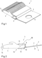
- the 1 shows a knitting tool bar 1 with a first profile element 2 and a second profile element 3.
- the circuit boards 4 are connected to one another by a wire 5 .
- the first profile element 2 and the second profile element 3 each have cutouts 6, the cutouts 6 of the first profile element 2 and of the second profile element 3 lying one above the other in a connected state.
- the connected state describes a state in which the first profile element 2 is attached to the second profile element 3 or the first profile element 2 is connected to the second profile element 3 and thus form a space 15 into which the sinkers 4 can be inserted.
- the space 15 thus corresponds to the circuit board recording.
- Each of the profile elements 2, 3 has three sections which are each arranged at an angle to one another.
- a first section 7 of the first profile element 2 is arranged on a first section 8 of the second profile element 3 and connected to it.
- a second section 9 , 10 extends from the first section 7 , 8 .
- the first section 7 of the first profile element 2 is connected to the second section 9 of the first profile element 2 .
- a third section 11 of the first profile element 1 projects from the second section 9 of the first profile element 2 .
- a second section 10 of the second profile element 3 also extends from the first section 8 of the second profile element 3 . Starting from the second section 10 of the second profile element 3, the third section 12 and of the second profile element 3 continue.
- the second and third sections 9-12 of the first profile element 2 and of the second profile element 3 essentially form the space 15 in which a first region 13 of the board 4 is arranged.
- the first area 13 of the plate 4 is cohesively connected to the first profile element 2 and the second profile element 3 .
- a second area 14 in which the wire 5 is provided is arranged opposite the first area 13 .
- the wire 5 is materially connected to the circuit board 4 .
- the individual sections 7, 9, 11 of the first profile element 2 or 8, 10, 12 of the second profile element 3 are each arranged at an angle to the respectively adjacent section. It should be noted here that the third section 11 of the first profile element 2 and the third section 12 of the second profile element 3 are arranged essentially parallel to one another. The two second sections 9, 10 are inclined in the direction of the circuit board 4.
- the two profile elements 2, 3 are bonded together at their respective first section 7, 8.
- the profile elements 2, 3 can be connected to one another, for example, by means of an adhesive bond, a soldered bond, a welded bond or the like.
- an adhesive gauge (not shown) is used.
- the board can be aligned with position and repeat accuracy in the knitting tool bar 1 between the two profile elements 2, 3 by means of the adhesive gauge.
- the circuit board is glued in or otherwise connected or fixed in a cohesive manner. This can be done either extensively or selectively.
- the material used for the profile elements 2, 3 can be metal or stainless steel, for example.
- the respective material is selected on the basis of the specified environment and the load on the knitting tool bar 1.
- Fiber-reinforced plastics such as carbon-fiber or glass-fiber-reinforced plastic are also possible.
- the individual sections 7-12 of the profile elements 2, 3 can be adjusted. Accordingly, there is an asymmetrical structure of the profile elements 2, 3 or their sections 7-12 or a symmetrical structure of the individual sections 7-12.
- the profile elements 2, 3 can be designed in such a way that a low weight is achieved at the same time as high mechanical load-bearing capacity and a low tendency to vibrate.
- the wall thicknesses of the profile elements 2, 3 can continue to vary accordingly.
- the third sections 11, 12 can be designed differently. This relates, for example, to their length and/or inclination and/or material thickness.
Landscapes
- Engineering & Computer Science (AREA)
- Textile Engineering (AREA)
- Knitting Machines (AREA)
- Braiding, Manufacturing Of Bobbin-Net Or Lace, And Manufacturing Of Nets By Knotting (AREA)
Abstract
Description
- Die vorliegende Erfindung betrifft eine Wirkwerkzeugbarre einer Textilmaschine mit einer Platinenaufnahme zur Aufnahme mehrerer Platinen.
- Platinen werden an Ketten- und Kulierwirkmaschinen eingesetzt, um beispielsweise das Einschließen, das Verteilen oder das Abschlagen des Kettfadens durchzuführen.
- Üblicherweise werden derartige Wirkwerkzeugbarren mit einem Grundkörper ausgebildet, der aus einem Leichtmetall, wie Magnesium oder Aluminium, oder aus einem faserverstärkten Kunststoffmaterial gebildet ist. Diese Werkstoffe werden üblicherweise verwendet, um die Masse der Wirkwerkzeugbarre kleinzuhalten. Viele der am Wirkvorgang beteiligten Wirkwerkzeugbarren müssen bei einem Maschenbildungsvorgang zweimal beschleunigt und abgebremst werden. Je kleiner die Masse der Wirkwerkzeugbarre ist, desto geringer sind die auf die Wirkwerkzeugbarre wirkenden Kräfte. Damit kann der Verschleiß kleingehalten werden.
- Der Erfindung liegt die Aufgabe zugrunde, eine Wirkwerkzeugbarre vorzuschlagen, bei der eine hohe mechanische Belastbarkeit bei gleichzeitig geringem Gewicht vorliegt.
- Diese Aufgabe wird bei einer Wirkwerkzeugbarre der eingangs genannten Art durch die Merkmale des Anspruchs 1 gelöst. Vorteilhafte Ausgestaltungen ergeben sich aus den Unteransprüchen.
- Dabei weist die Platinenaufnahme ein erstes Profilelement und ein zweites Profilelement auf, wobei das erste Profilelement und das zweite Profilelement miteinander verbunden sind und einen Raum zur Aufnahme der Platinen aufweist. Die Profilelemente können entsprechend der mechanischen Gegebenheiten geformt werden und folglich verschiedene Querschnittsanordnungen aufweisen. Demnach können auch unterschiedliche Belastungen, wie beispielsweise Schwingungen, berücksichtigt werden, so dass die Wirkwerkzeugbarre trotz eines geringen Gewichts eine hohe mechanische Belastbarkeit und eine geringe Schwingungsanfälligkeit aufweist. Dabei kann das erste Profilelement verschieden von dem zweiten Profilelement ausgestaltet sein. Dies ermöglicht eine hohe Flexibilität und Anpassbarkeit der Profilelemente an unterschiedliche Belastungen und Schwingungen. Außerdem können bei Profilelementen unterschiedliche Bereiche unterschiedlich gestaltet sein, so dass beispielsweise eine Wandstärke oder eine Form einzelner Bereiche variiert werden kann. Dadurch wird bei einem geringen Gewicht eine hohe mechanische Belastbarkeit erreicht. Die Platinen werden in dem Raum befestigt, wobei der Raum der Platinenaufnahme entspricht. Diese Befestigung kann beispielsweise durch Einkleben oder Schweißen oder eine andere stoffschlüssige Verbindungen erfolgen. Dabei kann zur Positionierung der Platinen in dem Raum eine Lehre benutzt werden, um somit eine wiederholgenaue Positionierung der einzelnen Platinen zu erreichen.
- Vorzugsweise sind das erste Profilelement und das zweite Profilelement stoffschlüssig miteinander verbunden. Ein stoffschlüssiger Verbund ist beispielsweise eine Klebeverbindung, Lötverbindung oder eine Schweißverbindung. Je nach Ausführung des Stoffschlusses können die Profilelemente wieder voneinander gelöst werden. Der Stoffschluss stellt eine einfache Möglichkeit dar, Profilelemente miteinander zu verbinden, wobei die Verbindung eine leichte Verbindung darstellt.
- Vorzugsweise sind die Platinen durch einen Draht miteinander verbunden. Durch den Draht wird eine weitere Verbindung der Platinen erreicht, so dass die Platinen untereinander und miteinander verbunden sind. Dies führt zu einer guten mechanischen Belastbarkeit der einzelnen Platinen und einem stabilen Verbund der Platinen. Weiterhin können somit einzelne Bereiche der Platinen verstärkt werden. Als Draht soll vorliegend auch ein Seil oder ein Stab verstanden werden.
- Vorzugsweise sind der Draht und die Platinen stoffschlüssig miteinander verbunden. Durch den Stoffschluss können artgleiche und artunterschiedliche Materialien miteinander verbunden werden, so dass beispielsweise der Draht und die Platine nicht unbedingt aus dem gleichen Material bestehen müssen. Weiterhin kann der Stoffschluss an die vorliegenden Belastungen angepasst werden, so dass beispielsweise eine elastische oder eine steife Verbindung hergestellt werden kann. Dadurch wird eine hohe Flexibilität und Anpassbarkeit an die vorliegenden Gegebenheiten erreicht.
- Vorzugsweise weisen die Platinen einen ersten Bereich, in dem die Platinen mit der Platinenaufnahme verbunden sind, und einen zweiten Bereich auf, der sich vom ersten Bereich unterscheidet, wobei in dem zweiten Bereich die Platinen mit dem Draht verbunden sind. Folglich werden die Platinen in zwei unterschiedlichen Bereichen gehalten, was zu einer stabilen Befestigung der Platinen führt.
- Vorzugsweise ist der erste Bereich gegenüberliegend vom zweiten Bereich angeordnet. So ist der erste Bereich beispielsweise in einem ersten Endbereich der Platine angeordnet, und der zweite Bereich ist beispielsweise in einem dem ersten Endbereich gegenüberliegenden Endbereich vorgesehen. Dabei können sich die Bereiche je nach Ausführungsform beispielsweise in der Mitte bzw. in einem Mittenbereich der Platine treffen. In jedem Fall ist die Verbindung der Platinen mit dem Draht und die Verbindung der Platine mit den Profilelementen zumindest minimal voneinander beabstandet. Dadurch kann auch ein kleiner Bauraum zur Platinenbefestigung genutzt werden.
- Vorzugsweise weisen das erste Profilelement und das zweite Profilelement jeweils eine Aussparung auf, wobei die Aussparung des ersten Profilelementes mit der Aussparung des zweiten Profilelementes in einem verbundenen Zustand der Profilelemente übereinander liegen. Der verbundene Zustand der Profilelemente beschreibt einen Zustand, in dem die Profilelemente miteinander verbunden sind und den Raum zur Aufnahme der Platinen formen. Diese Verbindung kann, wie bereits oben beschrieben, beispielsweise durch einen Stoffschluss erfolgen. Durch die Aussparung kann die Wirkwerkzeugbarre an der Textilmaschine oder einer anderen Aufnahme befestigt werden. Weiterhin kann eine solche Aussparung zur Gewichtseinsparung dienen, so dass eine Aussparung zum Leichtbaugedanken der Wirkwerkzeugbarre dient. Folglich wird die Wirkwerkzeugbarre leicht gehalten.
- Vorzugsweise weist das erste Profilelement und das zweite Profilelement Metallblech als Hauptkomponente auf. Metallblech gibt es in einer Vielzahl unterschiedlicher Dicken und in unterschiedlichen Materialien, so dass auf besondere Gegebenheiten der Textilmaschine Rücksicht genommen werden kann.
- Vorzugsweise weist das erste Profilelement und das zweite Profilelement Edelstahl als Hauptkomponente auf. Edelstahl ist eine Stahllegierung, die nur eine geringe Neigung zum Rosten bzw. Oxidieren aufweist. Weiterhin ist Edelstahl in der Regel nicht magnetisch bzw. magnetisch leitend. Dadurch werden mögliche magnetische Kräfte, die auf die Wirkwerkzeugbarre wirken, klein gehalten. Folglich liegt eine geringe mechanische durch Magnete indizierte Belastung der Profilelemente vor.
- Vorzugsweise ist der Raum U-förmig begrenzt. Dabei beschreibt die U-förmige Begrenzung eine Begrenzung des Querschnittes in Erstreckungsrichtung der Profilelemente. So ist der Raum im Wesentlichen an drei Seiten begrenzt, wobei eine Seite offen ist. Dabei können die Seiten bzw. Begrenzungen der U-förmigen Begrenzung beispielsweise Winkel, Sicken oder Knicke aufweisen. Alternativ dazu kann der Raum in Erstreckungsrichtung der Profilelemente auch C-förmig, V-förmig oder dergleichen ausgestaltet sein. Dies ermöglicht ein einfaches Einsetzen der Platinen bei gleichzeitig geringem Gewicht und einer guten mechanischen Belastbarkeit.
- Vorzugsweise ist ein von dem Raum umgebender Bereich der Platine kürzer als ein von dem Raum hervorstehender Bereich der Platine. Die Platine wird also in einem begrenzten Raum bzw. Bereich gehalten, so dass die Halterung bzw. die Profilelemente entsprechend klein dimensioniert werden können. Folglich kann die Wirkwerkzeugbarre bzw. das erste Profilelement und das zweite Profilelement klein ausgeführt werden.
- Vorzugsweise weisen das erste Profilelement und das zweite Profilelement jeweils drei Abschnitte auf, wobei die Abschnitte eines jeden Profilelementes jeweils winklig zum benachbarten Abschnitt angeordnet sind, wobei in dem verbundenen Zustand ein erster Abschnitt des Profilelementes parallel zu einem ersten Abstand des zweiten Profilelementes angeordnet ist und jeweils ein zweiter Abschnitt benachbart zum ersten Abschnitt angeordnet ist, wobei jeweils ein dritter Abschnitt und ein erster Abschnitt an dem zweiten Abschnitt angeordnet ist. Folglich beschreibt jedes der Profilelemente im weitesten Sinne eine Z-Geometrie. Durch diese Z-Geometrie kann eine hohe mechanische Belastung aufgenommen werden, wobei gleichzeitig eine Schwingungsneigung gering gehalten wird. Außerdem kann durch die Geometrie der Raum zur Aufnahme der Platinen an die Platinen angepasst werden. Dies ermöglicht eine Anpassung der Profilelemente an die Platine, so dass hier eine gute Anpassung der Halterung an die Platinen ermöglicht wird.
- Vorzugsweise sind in dem verbundenen Zustand die beiden dritten Abschnitte im Wesentlichen parallel angeordnet und erstrecken sich in Richtung der Platine gleich weit. Dadurch wird ein einfaches Einsetzen der Platinen in den Raum ermöglicht. Weiterhin wird die Platine durch eine gleich weite Erstreckung der dritten Abschnitte gut gehalten. Dies erlaubt eine stabile Verbindung der Profilelemente mit den Platinen. Weiterhin wird dadurch eine hohe mechanische Belastbarkeit der Wirkwerkzeugbarre erreicht.
- Vorzugsweise ist der jeweils zweite Abschnitt des ersten Profilelementes und des zweiten Profilelementes in Richtung der Platine geneigt. Die Neigung des zweiten Abschnittes bzw. der zweiten Abschnitte in Richtung der Platinen erlaubt einen schwingungsgünstigen Zustand der Profilelemente und der Wirkwerkzeugbarre. Weiterhin führt die Neigung zu einer Wirkwerkzeugbarre, die mechanisch gut belastbar ist.
- Vorzugsweise ist der zweite Abschnitt des ersten Profilelementes länger als der zweite Abschnitt des zweiten Profilelementes. Dies erlaubt eine einfache Anpassung der Profilelemente und damit der Wirkwerkzeugbarre an unterschiedliche Platinen. Weiterhin kann dadurch die Belastung der Wirkwerkzeugbarre an eine vorherschende Belastung der Platine angepasst werden. Folglich können die Profilelemente stabil und an die mechanischen Gegebenheiten angepasst werden.
- Die Erfindung wird im Folgenden anhand eines bevorzugten Ausführungsbeispiels in Verbindung mit einer Zeichnung beschrieben. Hierin zeigen:
- Fig. 1
- eine Wirkwerkzeugbarre gemäß der vorliegenden Erfindung;
- Fig. 2
- eine Seitenansicht der Wirkwerkzeugbarre;
-
Fig. 1 zeigt eine Wirkwerkzeugbarre 1 mit einem ersten Profilelement 2 und einem zweiten Profilelement 3. Durch das erste Profilelement 2 und das zweite Profilelement 3 werden Platinen 4 gehalten. Die Platinen 4 sind durch einen Draht 5 miteinander verbunden. Das erste Profilelement 2 und das zweite Profilelement 3 weisen jeweils Aussparungen 6 auf, wobei die Aussparungen 6 des ersten Profilelementes 2 und des zweiten Profilelementes 3 in einem verbundenen Zustand übereinander liegen. Der verbundene Zustand beschreibt dabei einen Zustand, in dem das erste Profilelement 2 an dem zweiten Profilelement 3 befestigt ist bzw. das erste Profilelement 2 mit dem zweiten Profilelement 3 verbunden ist und somit einen Raum 15 formen, in den die Platinen 4 eingesetzt werden können. Der Raum 15 entspricht also der Platinenaufnahme. -
Fig. 2 zeigt die Wirkwerkzeugbarre 1 in einer Seitenansicht in Richtung der Erstreckungsrichtung der Profilelemente 2, 3. Jedes der Profilelemente 2, 3 weist drei Abschnitte auf, die jeweils winklig zueinander angeordnet sind. Dabei ist ein erster Abschnitt 7 des ersten Profilelementes 2 an einem ersten Abschnitt 8 des zweiten Profilelementes 3 angeordnet und mit diesem verbunden. Ausgehend von dem ersten Abschnitt 7, 8 erstreckt sich ein zweiter Abschnitt 9, 10. Der erste Abschnitt 7 des ersten Profilelementes 2 ist dabei mit dem zweiten Abschnitt 9 des ersten Profilelementes 2 verbunden. Von dem zweiten Abschnitt 9 des ersten Profilelementes 2 steht ein dritter Abschnitt 11 des ersten Profilelementes 1 ab. Ebenso geht von dem ersten Abschnitt 8 des zweiten Profilelementes 3 ein zweiter Abschnitt 10 des zweiten Profilelementes 3 aus. Ausgehend von dem zweiten Abschnitt 10 des zweiten Profilelementes 3 geht weiterhin der dritte Abschnitt 12 und des zweiten Profilelementes 3 ab. - Im Wesentlichen bilden die zweiten und dritten Abschnitte 9-12 des ersten Profilelementes 2 und des zweiten Profilelementes 3 den Raum 15, in dem ein erster Bereich 13 der Platine 4 angeordnet ist. Der erste Bereich 13 der Platine 4 ist stoffschlüssig mit dem ersten Profilelement 2 und dem zweiten Profilelement 3 verbunden.
- Gegenüberliegend zum ersten Bereich 13 ist ein zweiter Bereich 14 angeordnet, in dem der Draht 5 vorgesehen ist. Der Draht 5 ist dabei stoffschlüssig mit der Platine 4 verbunden.
- Die einzelnen Abschnitte 7, 9, 11 des ersten Profilelementes 2 oder 8, 10, 12 des zweiten Profilelementes 3 sind jeweils winklig zu dem jeweils benachbarten Abschnitt angeordnet. Dabei ist zu beachten, dass der dritte Abschnitt 11 des ersten Profilelementes 2 und der dritte Abschnitt 12 des zweiten Profilelementes 3 im Wesentlichen parallel zueinander angeordnet sind. Die beiden zweiten Abschnitte 9, 10 sind in Richtung der Platine 4 geneigt.
- Die beiden Profilelemente 2, 3 sind an ihrem jeweils ersten Abschnitt 7, 8 miteinander stoffschlüssig verbunden. Dabei können die Profilelemente 2, 3 beispielsweise durch eine Klebeverbindung, Lötverbindung, Schweißverbindung oder dergleichen miteinander verbunden sein.
- Zum Einsetzen der Platine 4 in den durch das erste Profilelement 2 und das zweite Profilelement 3 geschaffenen Raum 15 wird eine nicht dargestellte Klebelehre genutzt. Durch die Klebelehre kann die Platine positions- und wiederholgenau in der Wirkwerkzeugbarre 1 zwischen den beiden Profilelementen 2, 3 ausgerichtet werden. Weiterhin wird im Rahmen der Fixierung der Platine in der Wirkwerkzeugbarre 1 die Platine eingeklebt oder anderweitig stoffschlüssig verbunden oder fixiert. Dies kann entweder flächig oder punktuell erfolgen.
- Als Material der Profilelemente 2, 3 kann beispielsweise ein Metall oder ein Edelstahl eingesetzt werden. Die Auswahl des jeweiligen Materials erfolgt anhand der vorgegebenen Umgebung, und Belastung der Wirkwerkzeugbarre 1. Weiterhin sind faserverstärkte Kunststoffe wie beispielsweise kohlefaser- oder ein glasfaserverstärkter Kunststoff möglich.
- Je nach Art und Ausprägung der Platine 4 können die einzelnen Abschnitte 7-12 der Profilelemente 2, 3 angepasst werden. Dementsprechend ist ein asymmetrischer Aufbau der Profilelemente 2, 3 bzw. deren Abschnitten 7-12 gegeben oder eben ein symmetrischer Aufbau der einzelnen Abschnitte 7-12. In jedem Fall können die Profilelemente 2, 3 so gestaltet werden, dass ein geringes Gewicht bei gleichzeitig einer hohen mechanischen Belastbarkeit sowie geringer Schwingungsneigung erreicht wird. Entsprechend können weiterhin Wandstärken der Profilelemente 2, 3 variieren. Je nach Belastung und Ausführung der Platine können die dritten Abschnitte 11, 12 unterschiedlich ausgeführt sein. Dies bezieht sich beispielsweise auf deren Länge und/oder Neigung und/oder Materialstärke.
-
- 1
- Wirkwerkzeugbarre
- 2
- erstes Profilelement
- 3
- zweites Profilelement
- 4
- Platine
- 5
- Draht
- 6
- Aussparung
- 7
- erster Abschnitt des ersten Profilelementes
- 8
- erster Abschnitt des zweiten Profilelementes
- 9
- zweiter Abschnitt des ersten Profilelementes
- 10
- zweiter Abschnitt des zweiten Profilelementes
- 11
- dritter Abschnitt des ersten Profilelementes
- 12
- dritter Abschnitt des zweiten Profilelementes
- 13
- erster Bereich
- 14
- zweiter Bereich
- 15
- Raum
Claims (15)
- Wirkwerkzeugbarre (1) einer Textilmaschine mit einer Platinenaufnahme zur Aufnahme mehrerer Platinen (4), dadurch gekennzeichnet, dass die Platinenaufnahme ein erstes Profilelement (2) und ein zweites Profilelement (3) aufweist, wobei das erste Profilelement (2) und das zweite Profilelement (3) miteinander verbunden sind und einen Raum (15) zur Aufnahme der Platinen (4) aufweist.
- Wirkwerkzeugbarre (1) nach Anspruch 1, dadurch gekennzeichnet, dass das erste Profilelement (2) und das zweite Profilelement (3) stoffschlüssig miteinander verbunden sind.
- Wirkwerkzeugbarre nach Anspruch 1 oder 2, dadurch gekennzeichnet, dass die Platinen (4) durch einen Draht (5) miteinander verbunden sind.
- Wirkwerkzeugbarre nach einem der Ansprüche 1 bis 3, dadurch gekennzeichnet, dass der Draht (5) und die Platinen (4) stoffschlüssig miteinander verbunden sind.
- Wirkwerkzeugbarre nach einem der Ansprüche 1 bis 4, dadurch gekennzeichnet, dass die Platinen (4) einen ersten Bereich (13), in dem die Platinen (4) mit der Platinenaufnahme verbunden sind, und einen zweiten Bereich (14) aufweisen, der sich vom ersten Bereich (13) unterscheidet, wobei in dem zweiten Bereich (14) die Platinen (4) mit dem Draht (5) verbunden sind.
- Wirkwerkzeugbarre () nach einem der Ansprüche 1 bis 5, dadurch gekennzeichnet, dass der erste Bereich (13) gegenüberliegend vom zweiten Bereich (14) angeordnet ist.
- Wirkwerkzeugbarre nach einem der Ansprüche 1 bis 6, dadurch gekennzeichnet, dass das erste Profilelement (2) und das zweite Profilelement (3) jeweils eine Aussparung (6) aufweisen, wobei die Aussparung (6) des ersten Profilelementes (2) mit der Aussparung (6) des zweiten Profilelementes (3) in einem verbundenen Zustand der Profilelemente (2, 3) übereinander liegen.
- Wirkwerkzeugbarre nach einem der Ansprüche 1 bis 7, dadurch gekennzeichnet, dass das erste Profilelement (2) und das zweite Profilelement (3) Metallblech als Hauptkomponente aufweisen.
- Wirkwerkzeugbarre nach einem der Ansprüche 1 bis 8, dadurch gekennzeichnet, dass das erste Profilelement (2) und das zweite Profilelement (3) Edelstahl als Hauptkomponente aufweisen.
- Wirkwerkzeugbarre nach einem der Ansprüche 1 bis 9, dadurch gekennzeichnet, dass der Raum (15) U-förmig begrenzt ist.
- Wirkwerkzeugbarre nach einem der Ansprüche 1 bis 10, dadurch gekennzeichnet, dass ein von dem Raum (15) umgebener Bereich der Platine (4) kürzer ist als ein von dem Raum (15) hervorstehender Bereich der Platine (4).
- Wirkwerkzeugbarre nach einem der Ansprüche 1 bis 11, dadurch gekennzeichnet, dass das erste Profilelement (2) und das zweite Profilelement (3) jeweils drei Abschnitte (7, 9, 11 und 8, 10, 12) aufweisen, wobei die Abschnitte (7, 9, 11 und 8, 10, 12) eines jeden Profilelementes (2, 3) jeweils winklig zum benachbarten Abschnitt (7, 9, 11 und 8, 10, 12) angeordnet sind, wobei in dem verbundenen Zustand ein erster Abschnitt (7) des ersten Profilelementes (2) parallel zu einem erster Abschnitt (8) des zweiten Profilelementes (3) angeordnet ist, und jeweils ein zweiter Abschnitt (9, 10) benachbart zum ersten Abschnitt (7, 8) angeordnet ist, wobei jeweils ein dritter Abschnitt (11, 12) und ein erster Abschnitt (7, 8) an dem zweiten Abschnitt (9, 10) angeordnet ist.
- Wirkwerkzeugbarre (1) nach einem der Ansprüche 1 bis 12, dadurch gekennzeichnet, dass in dem verbundenen Zustand die beiden dritten Abschnitte (11, 12) im Wesentlichen parallel angeordnet sind und sich in Richtung der Platine (4) gleich weit erstrecken.
- Wirkwerkzeugbarre nach einem der Ansprüche 1 bis 13, dadurch gekennzeichnet, dass der jeweils zweite Abschnitt (9, 10) des ersten Profilelementes (2) und des zweiten Profilelementes (3) in Richtung der Platine (4) geneigt ist.
- Wirkwerkzeugbarre (1) nach einem der Ansprüche 1 bis 14, dadurch gekennzeichnet, dass der zweite Abschnitt (9) des ersten Profilelementes (2) länger ist als der zweite Abschnitt (10) des zweiten Profilelementes (3).
Priority Applications (5)
| Application Number | Priority Date | Filing Date | Title |
|---|---|---|---|
| EP21196804.5A EP4151789B1 (de) | 2021-09-15 | 2021-09-15 | Wirkwerkzeugbarre |
| ES21196804T ES3014430T3 (en) | 2021-09-15 | 2021-09-15 | Warp knitting tool bar |
| CN202210458607.9A CN115807285B (zh) | 2021-09-15 | 2022-04-28 | 编织工具梳栉 |
| TW111129855A TWI850727B (zh) | 2021-09-15 | 2022-08-09 | 編織工具梳櫛 |
| KR1020220116618A KR102796772B1 (ko) | 2021-09-15 | 2022-09-15 | 경편 도구 바아 |
Applications Claiming Priority (1)
| Application Number | Priority Date | Filing Date | Title |
|---|---|---|---|
| EP21196804.5A EP4151789B1 (de) | 2021-09-15 | 2021-09-15 | Wirkwerkzeugbarre |
Publications (2)
| Publication Number | Publication Date |
|---|---|
| EP4151789A1 true EP4151789A1 (de) | 2023-03-22 |
| EP4151789B1 EP4151789B1 (de) | 2024-12-11 |
Family
ID=78032353
Family Applications (1)
| Application Number | Title | Priority Date | Filing Date |
|---|---|---|---|
| EP21196804.5A Active EP4151789B1 (de) | 2021-09-15 | 2021-09-15 | Wirkwerkzeugbarre |
Country Status (5)
| Country | Link |
|---|---|
| EP (1) | EP4151789B1 (de) |
| KR (1) | KR102796772B1 (de) |
| CN (1) | CN115807285B (de) |
| ES (1) | ES3014430T3 (de) |
| TW (1) | TWI850727B (de) |
Citations (3)
| Publication number | Priority date | Publication date | Assignee | Title |
|---|---|---|---|---|
| KR200309586Y1 (ko) * | 2003-01-09 | 2003-04-16 | 김종명 | 편직기의 바늘교체기구 |
| EP1770194A1 (de) * | 2005-09-28 | 2007-04-04 | KARL MAYER TEXTILMASCHINENFABRIK GmbH | Wirkwerkzeug-Barre einer Wirkmaschine |
| CN104131409A (zh) * | 2014-07-12 | 2014-11-05 | 常德纺织机械有限公司 | 一种经编机的成圈工具 |
Family Cites Families (4)
| Publication number | Priority date | Publication date | Assignee | Title |
|---|---|---|---|---|
| DE19753590C1 (de) * | 1997-12-03 | 1999-05-12 | Mayer Textilmaschf | Wirkelemente tragendes Segment für Kettenwirkmaschinen |
| DE502004006772D1 (de) * | 2004-05-27 | 2008-05-21 | Mayer Textilmaschf | Wirkwerkzeug-Barre |
| EP1921024B1 (de) * | 2006-11-07 | 2010-01-27 | Groz-Beckert KG | Nadelaufnahmeeinrichtung |
| ES2927820T3 (es) * | 2020-11-06 | 2022-11-11 | Karl Mayer Stoll R&D Gmbh | Barra de herramientas de género de punto para una máquina de punto por urdimbre |
-
2021
- 2021-09-15 ES ES21196804T patent/ES3014430T3/es active Active
- 2021-09-15 EP EP21196804.5A patent/EP4151789B1/de active Active
-
2022
- 2022-04-28 CN CN202210458607.9A patent/CN115807285B/zh active Active
- 2022-08-09 TW TW111129855A patent/TWI850727B/zh active
- 2022-09-15 KR KR1020220116618A patent/KR102796772B1/ko active Active
Patent Citations (3)
| Publication number | Priority date | Publication date | Assignee | Title |
|---|---|---|---|---|
| KR200309586Y1 (ko) * | 2003-01-09 | 2003-04-16 | 김종명 | 편직기의 바늘교체기구 |
| EP1770194A1 (de) * | 2005-09-28 | 2007-04-04 | KARL MAYER TEXTILMASCHINENFABRIK GmbH | Wirkwerkzeug-Barre einer Wirkmaschine |
| CN104131409A (zh) * | 2014-07-12 | 2014-11-05 | 常德纺织机械有限公司 | 一种经编机的成圈工具 |
Also Published As
| Publication number | Publication date |
|---|---|
| KR20230040300A (ko) | 2023-03-22 |
| CN115807285B (zh) | 2025-09-26 |
| CN115807285A (zh) | 2023-03-17 |
| TW202314075A (zh) | 2023-04-01 |
| ES3014430T3 (en) | 2025-04-22 |
| KR102796772B1 (ko) | 2025-04-16 |
| EP4151789B1 (de) | 2024-12-11 |
| TWI850727B (zh) | 2024-08-01 |
Similar Documents
| Publication | Publication Date | Title |
|---|---|---|
| DE2553628B2 (de) | Vorrichtung zum Verbinden eines Profilstabes mit an ihm anzubringenden Trägern für die Errichtung von Tragkonstruktionen | |
| WO2014001373A1 (de) | Vorrichtung und verfahren zum befestigen und ausrichten einer führungsschiene | |
| EP2048271A1 (de) | Wirkwerkzeuganordnung und Wirkwerkzeugverbund | |
| DE69207876T2 (de) | Bauelement | |
| EP4151789B1 (de) | Wirkwerkzeugbarre | |
| WO2010124790A1 (de) | Vorrichtung zum verbinden von wenigstens zwei gurten | |
| DE2805200B1 (de) | Verzugmatte fuer den Grubenausbau | |
| DE202009012533U1 (de) | Eingiessbare Ankerschiene | |
| DE3304603C2 (de) | Bauteil, insbesondere Schäkel | |
| DE2633612A1 (de) | Elastischer halter oder puffer | |
| DE102013201988A1 (de) | Befestigungsanordnung zur Anbringung eines Geräts, insbesondere eines Fahrzeugheizgeräts, an einer Trägerstruktur | |
| EP0510399B1 (de) | Halter für Andruckspindeln an Spannvorrichtungen | |
| DE731999C (de) | Leitungsklemme, insbesondere fuer Aluminiumleitungen | |
| EP1770194A1 (de) | Wirkwerkzeug-Barre einer Wirkmaschine | |
| DE3335798C1 (de) | Verzugmatte für den Grubenausbau | |
| DE29923408U1 (de) | Vorrichtung zur Aufnahme von Lasten an Betonbauwerken | |
| EP3415456A1 (de) | Sicherheitspuffer für einen aufzug oder kran | |
| DE102005024061A1 (de) | Zerstörungsfrei wiederlösbare Befestigungsmethode aus Kraft-, Formschluss | |
| DE1086952B (de) | Sicherungsvorrichtung fuer Schrauben gegen Verlieren, insbesondere fuer Geraete der Fernmelde- oder Fernsprechtechnik | |
| DE4229370A1 (de) | Halteklammer zur axial verschiebbaren Befestigung von Stäben | |
| DE3600552A1 (de) | Kabelklemme | |
| DE1946130A1 (de) | Verankerungsvorrichtung | |
| AT99131B (de) | Befestigung der Nadeln in Nadelstäben für Spinnereimaschinen. | |
| AT253573B (de) | Anordnung zur Befestigung einer Schiene | |
| DE29806367U1 (de) | Verbindungsanker für Sandwichelement |
Legal Events
| Date | Code | Title | Description |
|---|---|---|---|
| PUAI | Public reference made under article 153(3) epc to a published international application that has entered the european phase |
Free format text: ORIGINAL CODE: 0009012 |
|
| STAA | Information on the status of an ep patent application or granted ep patent |
Free format text: STATUS: REQUEST FOR EXAMINATION WAS MADE |
|
| 17P | Request for examination filed |
Effective date: 20220713 |
|
| AK | Designated contracting states |
Kind code of ref document: A1 Designated state(s): AL AT BE BG CH CY CZ DE DK EE ES FI FR GB GR HR HU IE IS IT LI LT LU LV MC MK MT NL NO PL PT RO RS SE SI SK SM TR |
|
| P01 | Opt-out of the competence of the unified patent court (upc) registered |
Effective date: 20230705 |
|
| GRAP | Despatch of communication of intention to grant a patent |
Free format text: ORIGINAL CODE: EPIDOSNIGR1 |
|
| STAA | Information on the status of an ep patent application or granted ep patent |
Free format text: STATUS: GRANT OF PATENT IS INTENDED |
|
| RIC1 | Information provided on ipc code assigned before grant |
Ipc: D04B 27/06 20060101AFI20240627BHEP |
|
| INTG | Intention to grant announced |
Effective date: 20240724 |
|
| GRAS | Grant fee paid |
Free format text: ORIGINAL CODE: EPIDOSNIGR3 |
|
| GRAA | (expected) grant |
Free format text: ORIGINAL CODE: 0009210 |
|
| STAA | Information on the status of an ep patent application or granted ep patent |
Free format text: STATUS: THE PATENT HAS BEEN GRANTED |
|
| AK | Designated contracting states |
Kind code of ref document: B1 Designated state(s): AL AT BE BG CH CY CZ DE DK EE ES FI FR GB GR HR HU IE IS IT LI LT LU LV MC MK MT NL NO PL PT RO RS SE SI SK SM TR |
|
| REG | Reference to a national code |
Ref country code: GB Ref legal event code: FG4D Free format text: NOT ENGLISH |
|
| REG | Reference to a national code |
Ref country code: CH Ref legal event code: EP |
|
| REG | Reference to a national code |
Ref country code: DE Ref legal event code: R096 Ref document number: 502021006062 Country of ref document: DE |
|
| REG | Reference to a national code |
Ref country code: IE Ref legal event code: FG4D Free format text: LANGUAGE OF EP DOCUMENT: GERMAN |
|
| REG | Reference to a national code |
Ref country code: LT Ref legal event code: MG9D |
|
| PG25 | Lapsed in a contracting state [announced via postgrant information from national office to epo] |
Ref country code: HR Free format text: LAPSE BECAUSE OF FAILURE TO SUBMIT A TRANSLATION OF THE DESCRIPTION OR TO PAY THE FEE WITHIN THE PRESCRIBED TIME-LIMIT Effective date: 20241211 |
|
| PG25 | Lapsed in a contracting state [announced via postgrant information from national office to epo] |
Ref country code: FI Free format text: LAPSE BECAUSE OF FAILURE TO SUBMIT A TRANSLATION OF THE DESCRIPTION OR TO PAY THE FEE WITHIN THE PRESCRIBED TIME-LIMIT Effective date: 20241211 |
|
| PG25 | Lapsed in a contracting state [announced via postgrant information from national office to epo] |
Ref country code: BG Free format text: LAPSE BECAUSE OF FAILURE TO SUBMIT A TRANSLATION OF THE DESCRIPTION OR TO PAY THE FEE WITHIN THE PRESCRIBED TIME-LIMIT Effective date: 20241211 |
|
| REG | Reference to a national code |
Ref country code: NL Ref legal event code: MP Effective date: 20241211 |
|
| REG | Reference to a national code |
Ref country code: ES Ref legal event code: FG2A Ref document number: 3014430 Country of ref document: ES Kind code of ref document: T3 Effective date: 20250422 |
|
| PG25 | Lapsed in a contracting state [announced via postgrant information from national office to epo] |
Ref country code: NO Free format text: LAPSE BECAUSE OF FAILURE TO SUBMIT A TRANSLATION OF THE DESCRIPTION OR TO PAY THE FEE WITHIN THE PRESCRIBED TIME-LIMIT Effective date: 20250311 |
|
| PG25 | Lapsed in a contracting state [announced via postgrant information from national office to epo] |
Ref country code: LV Free format text: LAPSE BECAUSE OF FAILURE TO SUBMIT A TRANSLATION OF THE DESCRIPTION OR TO PAY THE FEE WITHIN THE PRESCRIBED TIME-LIMIT Effective date: 20241211 Ref country code: GR Free format text: LAPSE BECAUSE OF FAILURE TO SUBMIT A TRANSLATION OF THE DESCRIPTION OR TO PAY THE FEE WITHIN THE PRESCRIBED TIME-LIMIT Effective date: 20250312 |
|
| PG25 | Lapsed in a contracting state [announced via postgrant information from national office to epo] |
Ref country code: RS Free format text: LAPSE BECAUSE OF FAILURE TO SUBMIT A TRANSLATION OF THE DESCRIPTION OR TO PAY THE FEE WITHIN THE PRESCRIBED TIME-LIMIT Effective date: 20250311 |
|
| PG25 | Lapsed in a contracting state [announced via postgrant information from national office to epo] |
Ref country code: NL Free format text: LAPSE BECAUSE OF FAILURE TO SUBMIT A TRANSLATION OF THE DESCRIPTION OR TO PAY THE FEE WITHIN THE PRESCRIBED TIME-LIMIT Effective date: 20241211 |
|
| PG25 | Lapsed in a contracting state [announced via postgrant information from national office to epo] |
Ref country code: SM Free format text: LAPSE BECAUSE OF FAILURE TO SUBMIT A TRANSLATION OF THE DESCRIPTION OR TO PAY THE FEE WITHIN THE PRESCRIBED TIME-LIMIT Effective date: 20241211 |
|
| PG25 | Lapsed in a contracting state [announced via postgrant information from national office to epo] |
Ref country code: PL Free format text: LAPSE BECAUSE OF FAILURE TO SUBMIT A TRANSLATION OF THE DESCRIPTION OR TO PAY THE FEE WITHIN THE PRESCRIBED TIME-LIMIT Effective date: 20241211 |
|
| PG25 | Lapsed in a contracting state [announced via postgrant information from national office to epo] |
Ref country code: IS Free format text: LAPSE BECAUSE OF FAILURE TO SUBMIT A TRANSLATION OF THE DESCRIPTION OR TO PAY THE FEE WITHIN THE PRESCRIBED TIME-LIMIT Effective date: 20250411 |
|
| PG25 | Lapsed in a contracting state [announced via postgrant information from national office to epo] |
Ref country code: PT Free format text: LAPSE BECAUSE OF FAILURE TO SUBMIT A TRANSLATION OF THE DESCRIPTION OR TO PAY THE FEE WITHIN THE PRESCRIBED TIME-LIMIT Effective date: 20250411 |
|
| PG25 | Lapsed in a contracting state [announced via postgrant information from national office to epo] |
Ref country code: EE Free format text: LAPSE BECAUSE OF FAILURE TO SUBMIT A TRANSLATION OF THE DESCRIPTION OR TO PAY THE FEE WITHIN THE PRESCRIBED TIME-LIMIT Effective date: 20241211 |
|
| PG25 | Lapsed in a contracting state [announced via postgrant information from national office to epo] |
Ref country code: RO Free format text: LAPSE BECAUSE OF FAILURE TO SUBMIT A TRANSLATION OF THE DESCRIPTION OR TO PAY THE FEE WITHIN THE PRESCRIBED TIME-LIMIT Effective date: 20241211 |
|
| PG25 | Lapsed in a contracting state [announced via postgrant information from national office to epo] |
Ref country code: SK Free format text: LAPSE BECAUSE OF FAILURE TO SUBMIT A TRANSLATION OF THE DESCRIPTION OR TO PAY THE FEE WITHIN THE PRESCRIBED TIME-LIMIT Effective date: 20241211 |
|
| PG25 | Lapsed in a contracting state [announced via postgrant information from national office to epo] |
Ref country code: CZ Free format text: LAPSE BECAUSE OF FAILURE TO SUBMIT A TRANSLATION OF THE DESCRIPTION OR TO PAY THE FEE WITHIN THE PRESCRIBED TIME-LIMIT Effective date: 20241211 |
|
| PG25 | Lapsed in a contracting state [announced via postgrant information from national office to epo] |
Ref country code: SE Free format text: LAPSE BECAUSE OF FAILURE TO SUBMIT A TRANSLATION OF THE DESCRIPTION OR TO PAY THE FEE WITHIN THE PRESCRIBED TIME-LIMIT Effective date: 20241211 |
|
| REG | Reference to a national code |
Ref country code: DE Ref legal event code: R097 Ref document number: 502021006062 Country of ref document: DE |
|
| PG25 | Lapsed in a contracting state [announced via postgrant information from national office to epo] |
Ref country code: DK Free format text: LAPSE BECAUSE OF FAILURE TO SUBMIT A TRANSLATION OF THE DESCRIPTION OR TO PAY THE FEE WITHIN THE PRESCRIBED TIME-LIMIT Effective date: 20241211 |
|
| PGFP | Annual fee paid to national office [announced via postgrant information from national office to epo] |
Ref country code: DE Payment date: 20250926 Year of fee payment: 5 |
|
| PGFP | Annual fee paid to national office [announced via postgrant information from national office to epo] |
Ref country code: TR Payment date: 20250827 Year of fee payment: 5 Ref country code: IT Payment date: 20250922 Year of fee payment: 5 |
|
| PLBE | No opposition filed within time limit |
Free format text: ORIGINAL CODE: 0009261 |
|
| STAA | Information on the status of an ep patent application or granted ep patent |
Free format text: STATUS: NO OPPOSITION FILED WITHIN TIME LIMIT |
|
| PGFP | Annual fee paid to national office [announced via postgrant information from national office to epo] |
Ref country code: FR Payment date: 20250925 Year of fee payment: 5 Ref country code: AT Payment date: 20251020 Year of fee payment: 5 |
|
| REG | Reference to a national code |
Ref country code: CH Ref legal event code: L10 Free format text: ST27 STATUS EVENT CODE: U-0-0-L10-L00 (AS PROVIDED BY THE NATIONAL OFFICE) Effective date: 20251022 |
|
| 26N | No opposition filed |
Effective date: 20250912 |
|
| PGFP | Annual fee paid to national office [announced via postgrant information from national office to epo] |
Ref country code: ES Payment date: 20251015 Year of fee payment: 5 |
|
| REG | Reference to a national code |
Ref country code: CH Ref legal event code: H13 Free format text: ST27 STATUS EVENT CODE: U-0-0-H10-H13 (AS PROVIDED BY THE NATIONAL OFFICE) Effective date: 20260504 |
|
| PG25 | Lapsed in a contracting state [announced via postgrant information from national office to epo] |
Ref country code: LU Free format text: LAPSE BECAUSE OF NON-PAYMENT OF DUE FEES Effective date: 20250915 |
|
| GBPC | Gb: european patent ceased through non-payment of renewal fee |
Effective date: 20250915 |
|
| REG | Reference to a national code |
Ref country code: BE Ref legal event code: MM Effective date: 20250930 |
|
| PG25 | Lapsed in a contracting state [announced via postgrant information from national office to epo] |
Ref country code: LT Free format text: LAPSE BECAUSE OF FAILURE TO SUBMIT A TRANSLATION OF THE DESCRIPTION OR TO PAY THE FEE WITHIN THE PRESCRIBED TIME-LIMIT Effective date: 20241211 |
|
| PG25 | Lapsed in a contracting state [announced via postgrant information from national office to epo] |
Ref country code: MC Free format text: LAPSE BECAUSE OF FAILURE TO SUBMIT A TRANSLATION OF THE DESCRIPTION OR TO PAY THE FEE WITHIN THE PRESCRIBED TIME-LIMIT Effective date: 20241211 |
|
| PG25 | Lapsed in a contracting state [announced via postgrant information from national office to epo] |
Ref country code: GB Free format text: LAPSE BECAUSE OF NON-PAYMENT OF DUE FEES Effective date: 20250915 |
|
| PG25 | Lapsed in a contracting state [announced via postgrant information from national office to epo] |
Ref country code: BE Free format text: LAPSE BECAUSE OF NON-PAYMENT OF DUE FEES Effective date: 20250930 Ref country code: IE Free format text: LAPSE BECAUSE OF NON-PAYMENT OF DUE FEES Effective date: 20250915 Ref country code: CH Free format text: LAPSE BECAUSE OF NON-PAYMENT OF DUE FEES Effective date: 20250930 |