EP4137714B1 - Kraftübertragungsvorrichtung - Google Patents
Kraftübertragungsvorrichtung Download PDFInfo
- Publication number
- EP4137714B1 EP4137714B1 EP20930753.7A EP20930753A EP4137714B1 EP 4137714 B1 EP4137714 B1 EP 4137714B1 EP 20930753 A EP20930753 A EP 20930753A EP 4137714 B1 EP4137714 B1 EP 4137714B1
- Authority
- EP
- European Patent Office
- Prior art keywords
- clutch
- driving
- pressing
- weight
- torque region
- Prior art date
- Legal status (The legal status is an assumption and is not a legal conclusion. Google has not performed a legal analysis and makes no representation as to the accuracy of the status listed.)
- Active
Links
Images


Classifications
-
- F—MECHANICAL ENGINEERING; LIGHTING; HEATING; WEAPONS; BLASTING
- F16—ENGINEERING ELEMENTS AND UNITS; GENERAL MEASURES FOR PRODUCING AND MAINTAINING EFFECTIVE FUNCTIONING OF MACHINES OR INSTALLATIONS; THERMAL INSULATION IN GENERAL
- F16D—COUPLINGS FOR TRANSMITTING ROTATION; CLUTCHES; BRAKES
- F16D43/00—Automatic clutches
- F16D43/02—Automatic clutches actuated entirely mechanically
- F16D43/04—Automatic clutches actuated entirely mechanically controlled by angular speed
- F16D43/06—Automatic clutches actuated entirely mechanically controlled by angular speed with centrifugal masses actuating axially a movable pressure ring or the like
- F16D43/08—Automatic clutches actuated entirely mechanically controlled by angular speed with centrifugal masses actuating axially a movable pressure ring or the like the pressure ring actuating friction plates, cones or similar axially-movable friction surfaces
- F16D43/10—Automatic clutches actuated entirely mechanically controlled by angular speed with centrifugal masses actuating axially a movable pressure ring or the like the pressure ring actuating friction plates, cones or similar axially-movable friction surfaces the centrifugal masses acting directly on the pressure ring, no other actuating mechanism for the pressure ring being provided
-
- B—PERFORMING OPERATIONS; TRANSPORTING
- B60—VEHICLES IN GENERAL
- B60K—ARRANGEMENT OR MOUNTING OF PROPULSION UNITS OR OF TRANSMISSIONS IN VEHICLES; ARRANGEMENT OR MOUNTING OF PLURAL DIVERSE PRIME-MOVERS IN VEHICLES; AUXILIARY DRIVES FOR VEHICLES; INSTRUMENTATION OR DASHBOARDS FOR VEHICLES; ARRANGEMENTS IN CONNECTION WITH COOLING, AIR INTAKE, GAS EXHAUST OR FUEL SUPPLY OF PROPULSION UNITS IN VEHICLES
- B60K1/00—Arrangement or mounting of electrical propulsion units
- B60K1/02—Arrangement or mounting of electrical propulsion units comprising more than one electric motor
-
- B—PERFORMING OPERATIONS; TRANSPORTING
- B60—VEHICLES IN GENERAL
- B60K—ARRANGEMENT OR MOUNTING OF PROPULSION UNITS OR OF TRANSMISSIONS IN VEHICLES; ARRANGEMENT OR MOUNTING OF PLURAL DIVERSE PRIME-MOVERS IN VEHICLES; AUXILIARY DRIVES FOR VEHICLES; INSTRUMENTATION OR DASHBOARDS FOR VEHICLES; ARRANGEMENTS IN CONNECTION WITH COOLING, AIR INTAKE, GAS EXHAUST OR FUEL SUPPLY OF PROPULSION UNITS IN VEHICLES
- B60K17/00—Arrangement or mounting of transmissions in vehicles
- B60K17/02—Arrangement or mounting of transmissions in vehicles characterised by arrangement, location, or kind of clutch
-
- F—MECHANICAL ENGINEERING; LIGHTING; HEATING; WEAPONS; BLASTING
- F16—ENGINEERING ELEMENTS AND UNITS; GENERAL MEASURES FOR PRODUCING AND MAINTAINING EFFECTIVE FUNCTIONING OF MACHINES OR INSTALLATIONS; THERMAL INSULATION IN GENERAL
- F16D—COUPLINGS FOR TRANSMITTING ROTATION; CLUTCHES; BRAKES
- F16D13/00—Friction clutches
- F16D13/22—Friction clutches with axially-movable clutching members
- F16D13/38—Friction clutches with axially-movable clutching members with flat clutching surfaces, e.g. discs
- F16D13/52—Clutches with multiple lamellae ; Clutches in which three or more axially moveable members are fixed alternately to the shafts to be coupled and are pressed from one side towards an axially-located member
- F16D13/54—Clutches with multiple lamellae ; Clutches in which three or more axially moveable members are fixed alternately to the shafts to be coupled and are pressed from one side towards an axially-located member with means for increasing the effective force between the actuating sleeve or equivalent member and the pressure member
-
- F—MECHANICAL ENGINEERING; LIGHTING; HEATING; WEAPONS; BLASTING
- F16—ENGINEERING ELEMENTS AND UNITS; GENERAL MEASURES FOR PRODUCING AND MAINTAINING EFFECTIVE FUNCTIONING OF MACHINES OR INSTALLATIONS; THERMAL INSULATION IN GENERAL
- F16D—COUPLINGS FOR TRANSMITTING ROTATION; CLUTCHES; BRAKES
- F16D43/00—Automatic clutches
- F16D43/02—Automatic clutches actuated entirely mechanically
- F16D43/04—Automatic clutches actuated entirely mechanically controlled by angular speed
- F16D43/06—Automatic clutches actuated entirely mechanically controlled by angular speed with centrifugal masses actuating axially a movable pressure ring or the like
- F16D43/08—Automatic clutches actuated entirely mechanically controlled by angular speed with centrifugal masses actuating axially a movable pressure ring or the like the pressure ring actuating friction plates, cones or similar axially-movable friction surfaces
- F16D43/12—Automatic clutches actuated entirely mechanically controlled by angular speed with centrifugal masses actuating axially a movable pressure ring or the like the pressure ring actuating friction plates, cones or similar axially-movable friction surfaces the centrifugal masses acting on, or forming a part of, an actuating mechanism by which the pressure ring can also be actuated independently of the masses
-
- F—MECHANICAL ENGINEERING; LIGHTING; HEATING; WEAPONS; BLASTING
- F16—ENGINEERING ELEMENTS AND UNITS; GENERAL MEASURES FOR PRODUCING AND MAINTAINING EFFECTIVE FUNCTIONING OF MACHINES OR INSTALLATIONS; THERMAL INSULATION IN GENERAL
- F16D—COUPLINGS FOR TRANSMITTING ROTATION; CLUTCHES; BRAKES
- F16D43/00—Automatic clutches
- F16D43/30—Systems of a plurality of automatic clutches
-
- F—MECHANICAL ENGINEERING; LIGHTING; HEATING; WEAPONS; BLASTING
- F16—ENGINEERING ELEMENTS AND UNITS; GENERAL MEASURES FOR PRODUCING AND MAINTAINING EFFECTIVE FUNCTIONING OF MACHINES OR INSTALLATIONS; THERMAL INSULATION IN GENERAL
- F16D—COUPLINGS FOR TRANSMITTING ROTATION; CLUTCHES; BRAKES
- F16D47/00—Systems of clutches, or clutches and couplings, comprising devices of types grouped under at least two of the preceding guide headings
-
- F—MECHANICAL ENGINEERING; LIGHTING; HEATING; WEAPONS; BLASTING
- F16—ENGINEERING ELEMENTS AND UNITS; GENERAL MEASURES FOR PRODUCING AND MAINTAINING EFFECTIVE FUNCTIONING OF MACHINES OR INSTALLATIONS; THERMAL INSULATION IN GENERAL
- F16D—COUPLINGS FOR TRANSMITTING ROTATION; CLUTCHES; BRAKES
- F16D13/00—Friction clutches
- F16D13/22—Friction clutches with axially-movable clutching members
- F16D13/38—Friction clutches with axially-movable clutching members with flat clutching surfaces, e.g. discs
- F16D13/52—Clutches with multiple lamellae ; Clutches in which three or more axially moveable members are fixed alternately to the shafts to be coupled and are pressed from one side towards an axially-located member
- F16D13/54—Clutches with multiple lamellae ; Clutches in which three or more axially moveable members are fixed alternately to the shafts to be coupled and are pressed from one side towards an axially-located member with means for increasing the effective force between the actuating sleeve or equivalent member and the pressure member
- F16D13/56—Clutches with multiple lamellae ; Clutches in which three or more axially moveable members are fixed alternately to the shafts to be coupled and are pressed from one side towards an axially-located member with means for increasing the effective force between the actuating sleeve or equivalent member and the pressure member in which the clutching pressure is produced by springs only
- F16D2013/565—Clutches with multiple lamellae ; Clutches in which three or more axially moveable members are fixed alternately to the shafts to be coupled and are pressed from one side towards an axially-located member with means for increasing the effective force between the actuating sleeve or equivalent member and the pressure member in which the clutching pressure is produced by springs only with means for releasing the clutch pressure in case of back torque
-
- F—MECHANICAL ENGINEERING; LIGHTING; HEATING; WEAPONS; BLASTING
- F16—ENGINEERING ELEMENTS AND UNITS; GENERAL MEASURES FOR PRODUCING AND MAINTAINING EFFECTIVE FUNCTIONING OF MACHINES OR INSTALLATIONS; THERMAL INSULATION IN GENERAL
- F16D—COUPLINGS FOR TRANSMITTING ROTATION; CLUTCHES; BRAKES
- F16D43/00—Automatic clutches
- F16D43/02—Automatic clutches actuated entirely mechanically
- F16D43/20—Automatic clutches actuated entirely mechanically controlled by torque, e.g. overload-release clutches, slip-clutches with means by which torque varies the clutching pressure
- F16D43/21—Automatic clutches actuated entirely mechanically controlled by torque, e.g. overload-release clutches, slip-clutches with means by which torque varies the clutching pressure with friction members
- F16D43/213—Automatic clutches actuated entirely mechanically controlled by torque, e.g. overload-release clutches, slip-clutches with means by which torque varies the clutching pressure with friction members with axially applied torque-limiting friction surfaces
- F16D43/215—Automatic clutches actuated entirely mechanically controlled by torque, e.g. overload-release clutches, slip-clutches with means by which torque varies the clutching pressure with friction members with axially applied torque-limiting friction surfaces with flat friction surfaces, e.g. discs
- F16D43/216—Automatic clutches actuated entirely mechanically controlled by torque, e.g. overload-release clutches, slip-clutches with means by which torque varies the clutching pressure with friction members with axially applied torque-limiting friction surfaces with flat friction surfaces, e.g. discs with multiple lamellae
Definitions
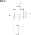
- the present invention relates to a power transmission apparatus that is able to freely transmit a rotational force of an input member to an output member or cut off the rotational force.
- a power transmission apparatus included in a motorcycle freely transmits a driving force of an engine to a transmission and a driving wheel or cuts off the driving force.
- a power transmission apparatus includes: an input member connected to an engine; an output member connected to a transmission and a driving wheel; a clutch member connected to the output member; and a pressure member that is able to move close to or away from the clutch member. Bringing the pressure member close to the clutch member presses driving and driven clutch plates against each other so as to transmit power therebetween. Bringing the pressure member away from the clutch member releases a pressing force exerted on the driving and driven clutch plates so as to cut off transmission of the power therebetween.
- a power transmission apparatus known in the art includes a centrifugal clutch means including a weight member that moves from a radially inner position of a groove to a radially outer position thereof with centrifugal force produced by rotation of a clutch housing and is thus able to press driving and driven clutch plates against each other.
- the power transmission apparatus known in the art is able to apply centrifugal force to the weight member in accordance with the rotation of the clutch housing caused by driving of an engine and is thus able to press the driving and driven clutch plates against each other so as to transmit a driving force of the engine to a wheel.
- the power transmission apparatus known in the art is provided with a pressing assist cam to increase a pressing force exerted on the driving and driven clutch plates when a rotational force received by an input member is transmittable to an output member. Accordingly, when a driver performs a clutch operation involving causing the driving and driven clutch plates to be pressed against each other, the power transmission apparatus known in the art is able to reduce an operating force so as to enable smooth power transmission.
- Document WO 2018/ 116 639 A1 relates to a power transmission device in which a clutch part is turned on by a pressing mechanism that uses a centrifugal element.
- This device includes a clutch housing, a clutch hub, a clutch center, a clutch part, a centrifugal pressing mechanism, and a torque transmitting part.
- the centrifugal pressing mechanism has a weight member that can move in the radial and axial directions by the rotation of the clutch housing, and the clutch part is pressed by the movement of the weight member.
- the clutch hub is coupled to the output part of the clutch part, and the clutch center is coupled to a member on the transmission side.
- the torque transmitting part transmits torque between the clutch hub and the clutch center, and a pressing force is applied to the clutch part when torque is transmitted from the clutch center to the clutch hub.
- Document JP 2010 060 106 A relates to a clutch device comprising a centrifugal clutch mechanism, mounted on the other side of a first pressure plate and moving according to the operation of a clutch lever provided with a second pressure plate actuated by a centrifugal weight, moved by a centrifugal force generated by the rotation of an engine, and making it possible for torque to be transmitted by the centrifugal weight, which is caused to act on the second pressure plate by a centrifugal force, when an engine rotation number is increased.
- Document EP 2 175 155 A2 relates to a friction clutch comprising a pressure plate movable in a predetermined direction to engage and/or disengage the clutch, a cam face formed on a side of the pressure plate, an opposing member having an opposing face that faces the cam face, a centrifugal weight arranged between the cam face and the opposing member, and an urging member configured to urge the centrifugal weight toward the cam face side via the opposing member.
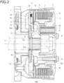
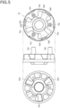
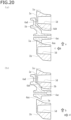
- the second clutch member 4b is an annular member provided with a flange 4bb.
- the driven clutch plates 7 are spline-fitted to a spline-fitting portion 4ba provided on the outer peripheral surface of the second clutch member 4b and are thus attached to the second clutch member 4b.
- the pressure member 5 is assembled to the clutch member (which includes the first clutch member 4a and the second clutch member 4b) such that the driving and driven clutch plates 6 and 7 are alternately stacked and secured between a flange 5c of the pressure member 5 and the flange 4bb of the second clutch member 4b.
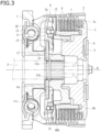
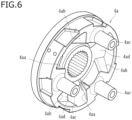
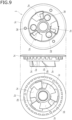
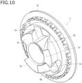
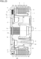
- the supporting member 13 is secured to a surface of the holding member 11, which is provided with the housing portions 11a. As illustrated in FIG. 14 , the supporting member 13 is provided with radially extending holding portions 13a.
- the holding portions 13a each conform to the groove 10c of the associated weight member 10, so that the weight members 10 are held by the holding member 11.
- the first surface X of each weight member 10 is centrally provided with the groove 10c extending in a direction from the radially inner position to the radially outer position. Causing each holding portion 13a to conform to the associated groove 10c allows the holding member 11 to hold the weight members 10 such that each weight member 10 is movable in a radial direction (i.e., in a direction from the radially inner position to the radially outer position).
Landscapes
- Engineering & Computer Science (AREA)
- General Engineering & Computer Science (AREA)
- Mechanical Engineering (AREA)
- Chemical & Material Sciences (AREA)
- Combustion & Propulsion (AREA)
- Transportation (AREA)
- One-Way And Automatic Clutches, And Combinations Of Different Clutches (AREA)
- Mechanical Operated Clutches (AREA)
Claims (6)
- Kraftübertragungsvorrichtung (K), umfassend:ein Kupplungselement (4a, 4b), das in einem Kupplungsgehäuse (2) untergebracht ist, das sich zusammen mit einem Eingangselement (1) dreht, das sich mit einer Antriebskraft eines Motors (E) eines Fahrzeugs dreht, wobei das Kupplungsgehäuse (2) mehrere Antriebskupplungsscheiben (6) aufweist, die daran befestigt sind, wobei das Kupplungselement (4a, 4b) mehrere angetriebene Kupplungsscheiben (7) aufweist, wobei die angetriebenen Kupplungsscheiben (7) abwechselnd mit den Antriebskupplungsscheiben (6) angeordnet sind, wobei das Kupplungselement (4a, 4b) mit einem Abtriebselement (3) verbunden ist, das ein Rad (T) des Fahrzeugs drehen kann;ein Druckelement (5), das zwischen einer Betriebsstellung, in der die antreibenden und angetriebenen Kupplungsscheiben (6, 7) gegeneinandergedrückt werden, um die Übertragung der Antriebskraft des Motors (E) auf das Rad (T) zu ermöglichen, und einer Nichtbetriebsstellung, in der eine auf die antreibenden und angetriebenen Kupplungsscheiben (6, 7) ausgeübte Drucckraft aufgehoben wird, um die Übertragung der Antriebskraft des Motors (E) auf das Rad (T) zu unterbrechen, bewegbar ist;eine Fliehkraftkupplungsvorrichtung (9) mit einem Gewichtselement (10), das durch die durch die Drehung des Kupplungsgehäuses (2) erzeugte Fliehkraft aus einer radial inneren Position in eine radial äußere Position bewegbar ist, wobei die Fliehkraftkupplungsvorrichtung (9) so ausgebildet ist, dass sie, wenn sich das Gewichtselement (10) in der radial äußeren Position befindet, die antreibenden und angetriebenen Kupplungsscheiben (6, 7) gegeneinanderdrückt, um die Übertragung der Antriebskraft des Motors (E) auf das Rad (T) zu ermöglichen, und so konfiguriert ist, dass sie, wenn sich das Gewichtselement (10) in der radial inneren Position befindet, die auf die antreibenden und angetriebenen Kupplungsscheiben (6, 7) ausgeübte Drucckraft aufhebt, um die Übertragung der Antriebskraft des Motors (E) auf das Rad (T) zu unterbrechen; undeine Druckunterstützungsnocke, um die auf die antreibenden und angetriebenen Kupplungsscheiben (6, 7) ausgeübte Druckkraft zu erhöhen,dadurch gekennzeichnet, dassder Druckunterstützungsnocke eine Neigungsfläche (4aa) des Kupplungselements (4a, 4b) und eine Neigungsfläche (5a) des Druckelements (5) umfasst, die einander gegenüberliegen,während der Bewegung des Gewichtsteils (10) der Fliehkraftkupplungsvorrichtung (9) von der radial inneren Position in die radial äußere Position und einer daraus resultierenden Erhöhung des vom Eingangselement (1) zum Ausgangsteil (3) übertragenen Drehmoments, die Vorrichtung (K) einen ersten Drehmomentbereich (a1), in dem die Vorrichtung (K) die Betätigung der Druckunterstützungsnocke einschränkt, und einen zweiten Drehmomentbereich (a2) aufweist, in dem die Vorrichtung (K) die Betätigung der Druckunterstützungsnocke zulässt.
- Kraftübertragungsvorrichtung (K) gemäß Anspruch 1, wobei
das Kupplungselement (4a, 4b) umfasst:ein erstes Kupplungselement (4a), das mit dem Abtriebselement (3) verbunden ist, undein zweites Kupplungselement (4b) mit den daran befestigten angetriebenen Kupplungsscheiben (7), undwobei die Druckunterstützungsnocke die Neigungsfläche (4aa) des ersten Kupplungselements (4a) und die Neigungsfläche (5a) des Druckelements (5), die einander zugewandt sind, umfasst. - Kraftübertragungsvorrichtung (K) gemäß Anspruch 2, wobei
die Vorrichtung (K) so konfiguriert ist, dass sie im ersten Drehmomentbereich (a1) das erste Kupplungselement (4a) und das Druckelement (5) in Anlage miteinander bringt, um die Betätigung der Druckunterstützungsnocke zu beschränken, und so konfiguriert ist, dass sie im zweiten Drehmomentbereich (a2) das erste Kupplungselement (4a) und das Druckelement (5) voneinander wegbewegt, um die Betätigung der Druckunterstützungsnocke zu ermöglichen. - Kraftübertragungsvorrichtung (K) gemäß Anspruch 3, wobei
die Fliehkraftkupplungsvorrichtung (9) so konfiguriert ist, dass sie im ersten Drehmomentbereich (a1) das zweite Kupplungselement (4b) so bewegt, dass das erste Kupplungselement (4a) und das Druckelement (5) in Anlage zueinander gehalten werden, und so konfiguriert ist, dass sie im zweiten Drehmomentbereich (a2) das zweite Kupplungselement (4b) und das Druckelement (5) so zu bewegen, dass das erste Kupplungselement (4a) und das Druckelement (5) voneinander beabstandet sind. - Kraftübertragungsvorrichtung (K) gemäß Anspruch 4, wobei
im Laufe des Betriebs der Fliehkraftkupplungsvorrichtung (9) ein Übergang vom ersten Drehmomentbereich (a1) zum zweiten Drehmomentbereich (a2) erfolgt. - Kraftübertragungsvorrichtung (K) gemäß Anspruch 1, wobei
die Vorrichtung (K) so konfiguriert ist, dass sie im ersten Drehmomentbereich (a1) das Kupplungselement (4a, 4b) und das Druckelement (5) in Anlage miteinander bringt, um die Betätigung der Druckunterstützungsnocke zu beschränken, und so konfiguriert ist, dass sie im zweiten Drehmomentbereich (a2) das Kupplungselement (4a, 4b) und das Druckelement (5) voneinander wegbewegt, um die Betätigung der Druckunterstützungsnocke zu ermöglichen.
Priority Applications (3)
| Application Number | Priority Date | Filing Date | Title |
|---|---|---|---|
| EP22215615.0A EP4191086B1 (de) | 2020-04-13 | 2020-09-14 | Kraftübertragungsvorrichtung |
| EP22215634.1A EP4180680B1 (de) | 2020-04-13 | 2020-09-14 | Kraftübertragungsvorrichtung |
| EP24171655.4A EP4421341B1 (de) | 2020-04-13 | 2020-09-14 | Kraftübertragungsvorrichtung |
Applications Claiming Priority (2)
| Application Number | Priority Date | Filing Date | Title |
|---|---|---|---|
| JP2020071889 | 2020-04-13 | ||
| PCT/JP2020/034740 WO2021210195A1 (ja) | 2020-04-13 | 2020-09-14 | 動力伝達装置 |
Related Child Applications (6)
| Application Number | Title | Priority Date | Filing Date |
|---|---|---|---|
| EP22215634.1A Division EP4180680B1 (de) | 2020-04-13 | 2020-09-14 | Kraftübertragungsvorrichtung |
| EP22215634.1A Division-Into EP4180680B1 (de) | 2020-04-13 | 2020-09-14 | Kraftübertragungsvorrichtung |
| EP22215615.0A Division EP4191086B1 (de) | 2020-04-13 | 2020-09-14 | Kraftübertragungsvorrichtung |
| EP22215615.0A Division-Into EP4191086B1 (de) | 2020-04-13 | 2020-09-14 | Kraftübertragungsvorrichtung |
| EP24171655.4A Division EP4421341B1 (de) | 2020-04-13 | 2020-09-14 | Kraftübertragungsvorrichtung |
| EP24171655.4A Division-Into EP4421341B1 (de) | 2020-04-13 | 2020-09-14 | Kraftübertragungsvorrichtung |
Publications (3)
| Publication Number | Publication Date |
|---|---|
| EP4137714A1 EP4137714A1 (de) | 2023-02-22 |
| EP4137714A4 EP4137714A4 (de) | 2024-07-24 |
| EP4137714B1 true EP4137714B1 (de) | 2025-06-25 |
Family
ID=78084756
Family Applications (4)
| Application Number | Title | Priority Date | Filing Date |
|---|---|---|---|
| EP20930753.7A Active EP4137714B1 (de) | 2020-04-13 | 2020-09-14 | Kraftübertragungsvorrichtung |
| EP22215634.1A Active EP4180680B1 (de) | 2020-04-13 | 2020-09-14 | Kraftübertragungsvorrichtung |
| EP22215615.0A Active EP4191086B1 (de) | 2020-04-13 | 2020-09-14 | Kraftübertragungsvorrichtung |
| EP24171655.4A Active EP4421341B1 (de) | 2020-04-13 | 2020-09-14 | Kraftübertragungsvorrichtung |
Family Applications After (3)
| Application Number | Title | Priority Date | Filing Date |
|---|---|---|---|
| EP22215634.1A Active EP4180680B1 (de) | 2020-04-13 | 2020-09-14 | Kraftübertragungsvorrichtung |
| EP22215615.0A Active EP4191086B1 (de) | 2020-04-13 | 2020-09-14 | Kraftübertragungsvorrichtung |
| EP24171655.4A Active EP4421341B1 (de) | 2020-04-13 | 2020-09-14 | Kraftübertragungsvorrichtung |
Country Status (5)
| Country | Link |
|---|---|
| US (7) | US11703093B2 (de) |
| EP (4) | EP4137714B1 (de) |
| JP (10) | JP7480281B2 (de) |
| CN (5) | CN121408383A (de) |
| WO (1) | WO2021210195A1 (de) |
Families Citing this family (10)
| Publication number | Priority date | Publication date | Assignee | Title |
|---|---|---|---|---|
| EP4137714B1 (de) * | 2020-04-13 | 2025-06-25 | Kabushiki Kaisha F.C.C. | Kraftübertragungsvorrichtung |
| EP4339474B1 (de) * | 2022-09-13 | 2024-12-11 | Kabushiki Kaisha F.C.C. | Kupplungsvorrichtung, motorrad und verfahren zur herstellung einer druckplatte |
| JP7692116B2 (ja) * | 2022-10-20 | 2025-06-12 | 株式会社エフ・シー・シー | 動力伝達装置 |
| EP4567292A4 (de) * | 2023-01-11 | 2026-01-07 | Fcc Kk | Kraftübertragungsvorrichtung |
| WO2025041521A1 (ja) * | 2023-08-23 | 2025-02-27 | 株式会社エフ・シー・シー | クラッチ装置 |
| WO2025203895A1 (ja) * | 2024-03-25 | 2025-10-02 | 株式会社エフ・シー・シー | クラッチ装置 |
| WO2025205397A1 (ja) * | 2024-03-25 | 2025-10-02 | 株式会社エフ・シー・シー | クラッチ装置 |
| WO2025204500A1 (ja) * | 2024-03-25 | 2025-10-02 | 株式会社エフ・シー・シー | クラッチ装置 |
| JP7742519B1 (ja) * | 2024-03-25 | 2025-09-19 | 株式会社エフ・シー・シー | クラッチ装置 |
| JP7651054B1 (ja) * | 2024-11-18 | 2025-03-25 | 株式会社エフ・シー・シー | クラッチ装置 |
Family Cites Families (43)
| Publication number | Priority date | Publication date | Assignee | Title |
|---|---|---|---|---|
| JPS382408B1 (de) * | 1960-11-17 | 1963-03-22 | ||
| JPS3924108Y1 (de) * | 1962-02-05 | 1964-08-19 | ||
| JPS5351544U (de) | 1976-10-05 | 1978-05-02 | ||
| JPS5913139A (ja) * | 1982-07-14 | 1984-01-23 | Yamaha Motor Co Ltd | 遠心式多板クラツチ |
| CS240762B1 (en) * | 1983-09-13 | 1986-02-13 | Vlastimil Bezouska | Friction multiple-disk clutch for motorcycles |
| JPH04316724A (ja) * | 1991-04-15 | 1992-11-09 | Yamaha Motor Co Ltd | 多板遠心クラッチ |
| JP3547849B2 (ja) * | 1995-05-19 | 2004-07-28 | 本田技研工業株式会社 | 遠心クラッチ |
| JPH11159547A (ja) * | 1997-11-28 | 1999-06-15 | Suzuki Motor Corp | 車両用自動遠心クラッチ装置 |
| US6533056B1 (en) * | 2000-04-25 | 2003-03-18 | Bud A. Maimone | Motorcycle automatic clutch with manual release |
| US6705446B2 (en) | 2001-06-07 | 2004-03-16 | Drussel Wilfley Design, Llc | Automatic clutch with manual override control mechanism |
| US7014026B2 (en) * | 2001-06-07 | 2006-03-21 | Drussel Wilfley Design, L.L.C. | Manual/automatic pressure control mechanism for centrifugal clutch |
| JP4223461B2 (ja) * | 2004-11-09 | 2009-02-12 | 株式会社エフ・シー・シー | 動力伝達装置 |
| JP4911507B2 (ja) | 2007-03-26 | 2012-04-04 | ヤマハ発動機株式会社 | クラッチおよびそれを備えた鞍乗型車両 |
| JP2009068694A (ja) * | 2007-08-20 | 2009-04-02 | Yamaha Motor Co Ltd | クラッチ、無段変速機、それらを備えるエンジンユニット、及び鞍乗型車両 |
| US20090107794A1 (en) * | 2007-10-31 | 2009-04-30 | Brp-Rotax Gmbh & Co. Kg | Clutch actuation system |
| JP2009127701A (ja) * | 2007-11-21 | 2009-06-11 | Yamaha Motor Co Ltd | 遠心クラッチを備えた自動二輪車 |
| JP2009127702A (ja) * | 2007-11-21 | 2009-06-11 | Yamaha Motor Co Ltd | 多板式遠心クラッチおよびそれを備えた車両 |
| JP2009197990A (ja) * | 2008-02-25 | 2009-09-03 | Yamaha Motor Co Ltd | 遠心クラッチを備えた自動二輪車 |
| JP2009197991A (ja) * | 2008-02-25 | 2009-09-03 | Yamaha Motor Co Ltd | 摩擦クラッチ |
| JP5208628B2 (ja) | 2008-09-05 | 2013-06-12 | 本田技研工業株式会社 | クラッチ装置 |
| JP3155714U (ja) * | 2008-10-10 | 2009-11-26 | ヤマハ発動機株式会社 | 摩擦クラッチおよびそれを備えた車両 |
| JP3155713U (ja) * | 2008-10-10 | 2009-11-26 | ヤマハ発動機株式会社 | 遠心式多板摩擦クラッチおよびそれを備えた車両 |
| US7810624B1 (en) * | 2010-01-28 | 2010-10-12 | Drussel Wilfley Design Llc | Centrifugal clutch with expansion ring assembly |
| JP5503320B2 (ja) * | 2010-02-09 | 2014-05-28 | 本田技研工業株式会社 | クラッチ装置 |
| JP5444153B2 (ja) | 2010-07-29 | 2014-03-19 | 本田技研工業株式会社 | クラッチ装置 |
| JP2012057728A (ja) * | 2010-09-09 | 2012-03-22 | Honda Motor Co Ltd | 遠心クラッチ付き車両 |
| JP5786678B2 (ja) * | 2011-09-01 | 2015-09-30 | 株式会社ジェイテクト | 駆動力伝達装置 |
| JP5854900B2 (ja) | 2012-03-16 | 2016-02-09 | 株式会社エフ・シー・シー | 動力伝達装置 |
| JP2013221585A (ja) * | 2012-04-17 | 2013-10-28 | Yamaha Motor Co Ltd | 遠心クラッチを備えた自動二輪車 |
| DE112013002771T5 (de) | 2012-06-04 | 2015-04-30 | Kabushiki Kaisha F.C.C. | Leistungsübertragungsvorrichtung |
| JP6535346B2 (ja) * | 2014-12-04 | 2019-06-26 | 株式会社エフ・シー・シー | 動力伝達装置 |
| WO2016118751A1 (en) * | 2015-01-21 | 2016-07-28 | Paul Austin | Automatic clutch with manual override |
| JP6655430B2 (ja) * | 2016-03-03 | 2020-02-26 | 株式会社エフ・シー・シー | 動力伝達装置 |
| JP6892758B2 (ja) * | 2016-12-20 | 2021-07-07 | 株式会社エクセディ | 動力伝達装置 |
| JP6914649B2 (ja) * | 2016-12-20 | 2021-08-04 | 株式会社エクセディ | 動力伝達装置 |
| JP6774352B2 (ja) * | 2017-02-17 | 2020-10-21 | 株式会社エクセディ | トルク変動抑制装置、トルクコンバータ、及び動力伝達装置 |
| JP6894792B2 (ja) * | 2017-07-27 | 2021-06-30 | 株式会社エフ・シー・シー | 動力伝達装置 |
| JP2019039456A (ja) * | 2017-08-23 | 2019-03-14 | 株式会社エクセディ | トルク変動抑制装置、トルクコンバータ、及び動力伝達装置 |
| JP6502443B2 (ja) * | 2017-09-01 | 2019-04-17 | 株式会社エフ・シー・シー | 動力伝達装置 |
| JP6961427B2 (ja) * | 2017-09-01 | 2021-11-05 | 株式会社エフ・シー・シー | 動力伝達装置 |
| JP6640179B2 (ja) * | 2017-12-29 | 2020-02-05 | 本田技研工業株式会社 | 内燃機関のクラッチ装置 |
| WO2021210194A1 (ja) * | 2020-04-13 | 2021-10-21 | 株式会社エフ・シー・シー | 動力伝達装置 |
| EP4137714B1 (de) | 2020-04-13 | 2025-06-25 | Kabushiki Kaisha F.C.C. | Kraftübertragungsvorrichtung |
-
2020
- 2020-09-14 EP EP20930753.7A patent/EP4137714B1/de active Active
- 2020-09-14 US US17/918,396 patent/US11703093B2/en active Active
- 2020-09-14 EP EP22215634.1A patent/EP4180680B1/de active Active
- 2020-09-14 CN CN202511659166.9A patent/CN121408383A/zh active Pending
- 2020-09-14 EP EP22215615.0A patent/EP4191086B1/de active Active
- 2020-09-14 EP EP24171655.4A patent/EP4421341B1/de active Active
- 2020-09-14 CN CN202080099670.7A patent/CN115398115B/zh active Active
- 2020-09-14 CN CN202511661583.7A patent/CN121429729A/zh active Pending
- 2020-09-14 CN CN202310025248.2A patent/CN115899108A/zh active Pending
- 2020-09-14 WO PCT/JP2020/034740 patent/WO2021210195A1/ja not_active Ceased
- 2020-09-14 JP JP2022515190A patent/JP7480281B2/ja active Active
- 2020-09-14 CN CN202310024974.2A patent/CN115853922B/zh active Active
-
2022
- 2022-10-31 JP JP2022174446A patent/JP7526774B2/ja active Active
- 2022-10-31 JP JP2022174447A patent/JP7589212B2/ja active Active
- 2022-12-07 US US18/076,451 patent/US12098754B2/en active Active
- 2022-12-07 US US18/076,449 patent/US11885382B2/en active Active
-
2024
- 2024-02-20 JP JP2024024018A patent/JP2024050976A/ja active Pending
- 2024-02-20 JP JP2024024019A patent/JP7577880B2/ja active Active
- 2024-04-18 JP JP2024067782A patent/JP7692082B2/ja active Active
- 2024-06-24 US US18/751,443 patent/US12416339B2/en active Active
- 2024-08-26 JP JP2024144126A patent/JP7665848B2/ja active Active
- 2024-10-07 US US18/907,738 patent/US12398767B2/en active Active
-
2025
- 2025-01-15 JP JP2025005610A patent/JP2025039845A/ja active Pending
- 2025-01-29 JP JP2025013161A patent/JP2025063326A/ja active Pending
- 2025-05-28 JP JP2025089111A patent/JP2025113451A/ja active Pending
- 2025-07-24 US US19/279,135 patent/US20250347326A1/en active Pending
- 2025-08-18 US US19/302,345 patent/US20250369489A1/en active Pending
Also Published As
Similar Documents
| Publication | Publication Date | Title |
|---|---|---|
| EP4137714B1 (de) | Kraftübertragungsvorrichtung | |
| EP4194710B1 (de) | Kraftübertragungsvorrichtung | |
| EP4137715B1 (de) | Kraftübertragungsvorrichtung | |
| EP4137716A1 (de) | Kraftübertragungsvorrichtung | |
| EP4194711A1 (de) | Kraftübertragungsvorrichtung | |
| JP7805503B2 (ja) | 動力伝達装置 |
Legal Events
| Date | Code | Title | Description |
|---|---|---|---|
| STAA | Information on the status of an ep patent application or granted ep patent |
Free format text: STATUS: THE INTERNATIONAL PUBLICATION HAS BEEN MADE |
|
| PUAI | Public reference made under article 153(3) epc to a published international application that has entered the european phase |
Free format text: ORIGINAL CODE: 0009012 |
|
| STAA | Information on the status of an ep patent application or granted ep patent |
Free format text: STATUS: REQUEST FOR EXAMINATION WAS MADE |
|
| 17P | Request for examination filed |
Effective date: 20221109 |
|
| AK | Designated contracting states |
Kind code of ref document: A1 Designated state(s): AL AT BE BG CH CY CZ DE DK EE ES FI FR GB GR HR HU IE IS IT LI LT LU LV MC MK MT NL NO PL PT RO RS SE SI SK SM TR |
|
| DAV | Request for validation of the european patent (deleted) | ||
| DAX | Request for extension of the european patent (deleted) | ||
| REG | Reference to a national code |
Ref country code: DE Ref legal event code: R079 Free format text: PREVIOUS MAIN CLASS: F16D0013520000 Ipc: F16D0013540000 Ref document number: 602020053569 Country of ref document: DE |
|
| A4 | Supplementary search report drawn up and despatched |
Effective date: 20240620 |
|
| RIC1 | Information provided on ipc code assigned before grant |
Ipc: F16D 43/21 20060101ALI20240614BHEP Ipc: F16D 13/56 20060101ALI20240614BHEP Ipc: F16D 43/10 20060101ALI20240614BHEP Ipc: F16D 13/54 20060101AFI20240614BHEP |
|
| GRAP | Despatch of communication of intention to grant a patent |
Free format text: ORIGINAL CODE: EPIDOSNIGR1 |
|
| STAA | Information on the status of an ep patent application or granted ep patent |
Free format text: STATUS: GRANT OF PATENT IS INTENDED |
|
| INTG | Intention to grant announced |
Effective date: 20250411 |
|
| GRAS | Grant fee paid |
Free format text: ORIGINAL CODE: EPIDOSNIGR3 |
|
| GRAA | (expected) grant |
Free format text: ORIGINAL CODE: 0009210 |
|
| STAA | Information on the status of an ep patent application or granted ep patent |
Free format text: STATUS: THE PATENT HAS BEEN GRANTED |
|
| P01 | Opt-out of the competence of the unified patent court (upc) registered |
Free format text: CASE NUMBER: APP_19000/2025 Effective date: 20250421 |
|
| AK | Designated contracting states |
Kind code of ref document: B1 Designated state(s): AL AT BE BG CH CY CZ DE DK EE ES FI FR GB GR HR HU IE IS IT LI LT LU LV MC MK MT NL NO PL PT RO RS SE SI SK SM TR |
|
| REG | Reference to a national code |
Ref country code: GB Ref legal event code: FG4D |
|
| REG | Reference to a national code |
Ref country code: CH Ref legal event code: EP |
|
| REG | Reference to a national code |
Ref country code: DE Ref legal event code: R096 Ref document number: 602020053569 Country of ref document: DE |
|
| REG | Reference to a national code |
Ref country code: CH Ref legal event code: EP |
|
| REG | Reference to a national code |
Ref country code: IE Ref legal event code: FG4D |
|
| PG25 | Lapsed in a contracting state [announced via postgrant information from national office to epo] |
Ref country code: FI Free format text: LAPSE BECAUSE OF FAILURE TO SUBMIT A TRANSLATION OF THE DESCRIPTION OR TO PAY THE FEE WITHIN THE PRESCRIBED TIME-LIMIT Effective date: 20250625 |
|
| PGFP | Annual fee paid to national office [announced via postgrant information from national office to epo] |
Ref country code: DE Payment date: 20250923 Year of fee payment: 6 |
|
| REG | Reference to a national code |
Ref country code: LT Ref legal event code: MG9D |
|
| PG25 | Lapsed in a contracting state [announced via postgrant information from national office to epo] |
Ref country code: NO Free format text: LAPSE BECAUSE OF FAILURE TO SUBMIT A TRANSLATION OF THE DESCRIPTION OR TO PAY THE FEE WITHIN THE PRESCRIBED TIME-LIMIT Effective date: 20250925 Ref country code: GR Free format text: LAPSE BECAUSE OF FAILURE TO SUBMIT A TRANSLATION OF THE DESCRIPTION OR TO PAY THE FEE WITHIN THE PRESCRIBED TIME-LIMIT Effective date: 20250926 |
|
| PGFP | Annual fee paid to national office [announced via postgrant information from national office to epo] |
Ref country code: IT Payment date: 20250929 Year of fee payment: 6 |
|
| PG25 | Lapsed in a contracting state [announced via postgrant information from national office to epo] |
Ref country code: BG Free format text: LAPSE BECAUSE OF FAILURE TO SUBMIT A TRANSLATION OF THE DESCRIPTION OR TO PAY THE FEE WITHIN THE PRESCRIBED TIME-LIMIT Effective date: 20250625 |
|
| PGFP | Annual fee paid to national office [announced via postgrant information from national office to epo] |
Ref country code: GB Payment date: 20250927 Year of fee payment: 6 |
|
| PG25 | Lapsed in a contracting state [announced via postgrant information from national office to epo] |
Ref country code: HR Free format text: LAPSE BECAUSE OF FAILURE TO SUBMIT A TRANSLATION OF THE DESCRIPTION OR TO PAY THE FEE WITHIN THE PRESCRIBED TIME-LIMIT Effective date: 20250625 |
|
| PG25 | Lapsed in a contracting state [announced via postgrant information from national office to epo] |
Ref country code: RS Free format text: LAPSE BECAUSE OF FAILURE TO SUBMIT A TRANSLATION OF THE DESCRIPTION OR TO PAY THE FEE WITHIN THE PRESCRIBED TIME-LIMIT Effective date: 20250925 |
|
| PG25 | Lapsed in a contracting state [announced via postgrant information from national office to epo] |
Ref country code: LV Free format text: LAPSE BECAUSE OF FAILURE TO SUBMIT A TRANSLATION OF THE DESCRIPTION OR TO PAY THE FEE WITHIN THE PRESCRIBED TIME-LIMIT Effective date: 20250625 |
|
| REG | Reference to a national code |
Ref country code: NL Ref legal event code: MP Effective date: 20250625 |
|
| PG25 | Lapsed in a contracting state [announced via postgrant information from national office to epo] |
Ref country code: NL Free format text: LAPSE BECAUSE OF FAILURE TO SUBMIT A TRANSLATION OF THE DESCRIPTION OR TO PAY THE FEE WITHIN THE PRESCRIBED TIME-LIMIT Effective date: 20250625 |
|
| PG25 | Lapsed in a contracting state [announced via postgrant information from national office to epo] |
Ref country code: PT Free format text: LAPSE BECAUSE OF FAILURE TO SUBMIT A TRANSLATION OF THE DESCRIPTION OR TO PAY THE FEE WITHIN THE PRESCRIBED TIME-LIMIT Effective date: 20251027 |
|
| REG | Reference to a national code |
Ref country code: AT Ref legal event code: MK05 Ref document number: 1806709 Country of ref document: AT Kind code of ref document: T Effective date: 20250625 |
|
| PG25 | Lapsed in a contracting state [announced via postgrant information from national office to epo] |
Ref country code: IS Free format text: LAPSE BECAUSE OF FAILURE TO SUBMIT A TRANSLATION OF THE DESCRIPTION OR TO PAY THE FEE WITHIN THE PRESCRIBED TIME-LIMIT Effective date: 20251025 |
|
| PG25 | Lapsed in a contracting state [announced via postgrant information from national office to epo] |
Ref country code: AT Free format text: LAPSE BECAUSE OF FAILURE TO SUBMIT A TRANSLATION OF THE DESCRIPTION OR TO PAY THE FEE WITHIN THE PRESCRIBED TIME-LIMIT Effective date: 20250625 Ref country code: SM Free format text: LAPSE BECAUSE OF FAILURE TO SUBMIT A TRANSLATION OF THE DESCRIPTION OR TO PAY THE FEE WITHIN THE PRESCRIBED TIME-LIMIT Effective date: 20250625 |
|
| PG25 | Lapsed in a contracting state [announced via postgrant information from national office to epo] |
Ref country code: CZ Free format text: LAPSE BECAUSE OF FAILURE TO SUBMIT A TRANSLATION OF THE DESCRIPTION OR TO PAY THE FEE WITHIN THE PRESCRIBED TIME-LIMIT Effective date: 20250625 |
|
| PG25 | Lapsed in a contracting state [announced via postgrant information from national office to epo] |
Ref country code: PL Free format text: LAPSE BECAUSE OF FAILURE TO SUBMIT A TRANSLATION OF THE DESCRIPTION OR TO PAY THE FEE WITHIN THE PRESCRIBED TIME-LIMIT Effective date: 20250625 |
|
| PG25 | Lapsed in a contracting state [announced via postgrant information from national office to epo] |
Ref country code: EE Free format text: LAPSE BECAUSE OF FAILURE TO SUBMIT A TRANSLATION OF THE DESCRIPTION OR TO PAY THE FEE WITHIN THE PRESCRIBED TIME-LIMIT Effective date: 20250625 |
|
| PG25 | Lapsed in a contracting state [announced via postgrant information from national office to epo] |
Ref country code: SK Free format text: LAPSE BECAUSE OF FAILURE TO SUBMIT A TRANSLATION OF THE DESCRIPTION OR TO PAY THE FEE WITHIN THE PRESCRIBED TIME-LIMIT Effective date: 20250625 |
|
| PG25 | Lapsed in a contracting state [announced via postgrant information from national office to epo] |
Ref country code: ES Free format text: LAPSE BECAUSE OF FAILURE TO SUBMIT A TRANSLATION OF THE DESCRIPTION OR TO PAY THE FEE WITHIN THE PRESCRIBED TIME-LIMIT Effective date: 20250625 |