EP4132001A1 - Kopfbügelpolster - Google Patents
Kopfbügelpolster Download PDFInfo
- Publication number
- EP4132001A1 EP4132001A1 EP22188465.3A EP22188465A EP4132001A1 EP 4132001 A1 EP4132001 A1 EP 4132001A1 EP 22188465 A EP22188465 A EP 22188465A EP 4132001 A1 EP4132001 A1 EP 4132001A1
- Authority
- EP
- European Patent Office
- Prior art keywords
- headband
- padding
- closure
- recess
- padding element
- Prior art date
- Legal status (The legal status is an assumption and is not a legal conclusion. Google has not performed a legal analysis and makes no representation as to the accuracy of the status listed.)
- Granted
Links
Images

Classifications
-
- H—ELECTRICITY
- H04—ELECTRIC COMMUNICATION TECHNIQUE
- H04R—LOUDSPEAKERS, MICROPHONES, GRAMOPHONE PICK-UPS OR LIKE ACOUSTIC ELECTROMECHANICAL TRANSDUCERS; ELECTRIC HEARING AIDS; PUBLIC ADDRESS SYSTEMS
- H04R5/00—Stereophonic arrangements
- H04R5/033—Headphones for stereophonic communication
- H04R5/0335—Earpiece support, e.g. headbands or neckrests
Definitions
- the invention relates to a headband padding for a headband of headphones, having a padding element and a holding means for fixing the padding element to the headband, the padding element having a cushion side that can be placed against a head and an opposite side of the bracket, the holding means being designed to be lockable and reversibly detachable that the headband padding is attachable to the headband and detachable from the headband.
- the holding means can be closed in a non-positive and/or positive manner.
- the invention is based on the object of designing and arranging a headband padding in such a way that improved handling is ensured.
- the padding element has a width B and a length L and a first cutout, which is used to accommodate a headband, the padding element having a second cutout, which is used to accommodate a connecting cable of the headphones, the padding element a third recess for receiving another part of the headband, the first recess, the second recess and the third recess extending over the length L.
- the extension takes place over at least 50% of the length L. It can also be advantageous if the extension is more than 70%, 80%, 90% or 100% done.
- the cutout is advantageously on the side of the headband and extends over said part of the length L.
- the headband is integrated into the padding element and is not bulky, so that the headband padding can also be worn comfortably together with a head protection hood.
- the second recess is advantageously provided on the temple side. It also extends over the entire length L. This also ensures a defined positioning of the connection line within the headband padding. A flexible positioning in the direction of the length L, and thus a displacement of the connection line in the direction of the length L, is also possible within the second recess.
- the connecting cable is thus integrated into the headband padding and is not bulky, so that the headband padding can also be worn comfortably together with a head protection hood.
- the fact that the connection line is only laid in the second cutout means that it can be easily installed and removed if necessary.
- the third recess is also provided on the temple side. It also extends over the entire length L.
- the second recess can be provided with respect to a width B between the first and the third recess.
- the third recess in turn serves to accommodate a further part of the headband or a second headband segment, which can be positioned in a correspondingly defined manner and slidably accommodated within the recess in the direction of the length L.
- the first and third recesses have a maximum spacing with respect to the width B, which ensures optimal support or fixation on the user's head. All three recesses ensure an optimal fit and hold of the headband and the connecting cable on the one hand and a low overall height on the other hand with a view to wearing it together with or under a protective head hood.
- the respective cut-out can be a longitudinal groove, which is open at the top, within the cushion element act.
- the longitudinal groove is preferably also open laterally at the respective end area.
- the headband pad is also removable at any time for cleaning and/or decontamination or for replacement due to wear and tear.
- the holding means has at least one locking tab, by means of which the padding element can be fixed to the headband.
- the at least one cutout can be covered by means of the locking tab and a headband or a connecting line contained therein can be fixed accordingly.
- the closure tab extends over one cutout or a plurality of cutouts.
- the padding element can be fixed to the headband by means of the locking tabs, it being possible for the headband to be attached in the at least first recess.
- the closure means does not impede the cushioned abutment between the cushion member and the user's head.
- the holding means has a first closure means, in which case the at least one closure flap can be brought into closure with the padding element at least indirectly via the first closure means.
- the first closure means is attached to the bracket side.
- the padding element has a base body with an outer layer, the closure tabs being an integral part of the outer layer or if the closure tabs are formed by the outer layer.
- the outer layer including the closure tabs is possible.
- the holding means has a second closure means which can be brought into the releasable closure with the first closure means.
- the closure means is attached to the closure flap.
- the first and the second closure means can be cooperating elements of a Velcro fastener.
- a second means of closure advantageously in the embodiment of a hook-and-loop fastener element, a secure hold and easy opening and closing of the closure means are ensured.
- Other combinations of closure means are also conceivable, in which at least one side has Velcro-like properties such as hooks, while the other side has corresponding recesses, loops or the like for latching or hooking in the hooks.
- the respective closure tab is provided laterally on an edge of the padding element between the pillow side and the hanger side.
- the closure tab it is possible to close or turn over the closure tab on the side of the headband and correspondingly fix the headband.
- the locking tabs it is also conceivable to place the locking tabs in other zones on the side of the temples, as long as they ensure that the respective recesses are closed by turning them over.
- the pillow side is advantageously free of closure tabs.
- the padding element has at least one recess which extends over the width B.
- the recess extends over the entire width B and is provided on the temple side.
- the recess serves to make it easier to adjust the headband padding in relation to the basic curvature of the headband. As a result, creases or similar disruptive influences, especially on the cushion side, are avoided.
- the recess is designed as a groove which is open laterally in an end area and at the top.
- the longitudinal groove serves to accommodate a headband installed at the end of an earpiece and to accommodate a connecting line installed at the end of an earpiece.
- the inclusion in the longitudinal groove is effected by inserting the headband or the connection line into the longitudinal opening of the longitudinal groove which is open at the top, thus inserting it in a direction Re transverse to a direction RI in which the length L extends.
- an outer surface of the upholstery element which forms at least the cushion side, has no structure, is smooth, non-porous and/or waterproof. The outer surface is therefore easy to clean and decontaminate.
- the cushion side is designed without recesses and/or recesses. This ensures easy handling and easy application to a user's head.
- the padding element has a base body, with the base body being designed as a gel cushion.
- the outer layer is designed as a separate outer layer from the base body. The outer layer surrounds the base body at least partially or completely.
- Gel pads have known advantages in terms of their flexibility or adaptability and the cushioning properties associated therewith.
- a system is advantageous consisting of a headband padding as described above and with a cover in which the headband padding is integrated, with the cover being detachably attached to the headband padding.
- the cover can be made of washable fabric or textile. The cover can thus be cleaned separately. Due to the detachable cover, the connection line can be installed and removed or exchanged in a simple manner in the second recess or the headband in the first and third recess if necessary.
- a headband of a headphone is also provided, which is inserted into the headband padding.
- the headband which is accommodated in the first and third recess, can also be easily removed or exchanged due to the detachable cover. The same applies to replacing the headband padding with regard to the headband.
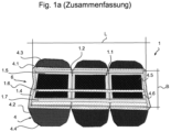
- the headband padding 1 shown is formed from a base body 1.3, such as silicone, which is surrounded by an outer layer 1.4.
- a base body 1.3 such as silicone
- an outer layer 1.4 Provided within the cushion element 1.1 formed in this way are three recesses 1.5, 1.6, 1.7, which are designed as upwardly open longitudinal grooves, and a recess 1.2 running at right angles thereto. The latter extends over the width B of the padding element 1.1, while the three recesses 1.5, 1.6, 1.7 extend over the length L of the padding element 1.1.
- the respective longitudinal groove 1.5, 1.6, 1.7 is preferably also open laterally at the respective end region 8a.
- the longitudinal groove serves to accommodate a headband 2.1 installed on the end of an earpiece 2 and to accommodate a connecting line 2.2 installed on an earpiece 2 at the end. It is placed in the longitudinal groove by inserting the headband 2.1 or the connection line 2.2 in the longitudinal opening 8b of the longitudinal groove 1.5, 1.6, 1.7, which is open at the top, thus inserting it in a direction Re transverse to the direction RI of the length L.
- the upholstery element 1.1 has a plurality of closure tabs 4.1 on one longitudinal side of the upholstery element 1.1 and, moreover, a plurality of closure tabs 4.2 on the opposite side of the upholstery element 1.1.
- the various locking tabs 4.1, 4.2 are in accordance with Figure 1b attached or articulated to an edge 1.8 of the padding element 1.1 and can be placed on the bracket side 6 of the padding element 1.1 via the recesses 1.5, 1.6, 1.7 located therein. The latter to close the recesses 1.5, 1.6, 1.7 or the headband 2.1 or connecting line 2.2 located therein.
- first closure means 4.3, 4.4 and, in addition, several second closure means 4.5, 4.6 are provided, which according to the embodiment Figure 1a to 4 are designed as Velcro.
- the closure tabs 4.1, 4.2 can be repeatedly detached from the side 6 of the hanger or fixed on the side 6 of the hanger.
- the padding element 1.1 has, as stated, a base body 1.3 which is preferably made of silicone and is encapsulated with an outer layer 1.4.
- the base body 1.3 can also consist of foam or a similar soft plastic.
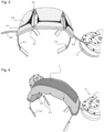
- the two headbands 2.1 are mounted in the two outer recesses, i.e. within the first recess 1.5 and within the third recess 1.7, while the connecting line 2.2 is mounted within the second recess 1.6, which is located between the two recesses 1.5, 1.7.
- the padding element 1.1 is kinked in the area of the recess 1.2, which runs over the course of the width B, so that an adaptation to the shape of the headband 2.1 is possible without the formation of folds.
- the padding element 1.1 attached to the headband 2.1 or the headband padding 1 formed in this way is provided with a fabric cover 7, as also in FIG Figure 1b shown.
- the cover 7 is also fastened using similar closure means such as hook and loop fasteners and can be correspondingly reversibly removed or installed and washed.
- the headband padding 1 designed in this way has a smooth, easy-to-decontaminate or easy-to-clean surface, at least on the cushion side 5, with cleaning being able to take place with the padding element 1.1 or with the headband padding 1 removed.
- the headband padding 1 can be exchanged via said closure tabs 4.1, 4.2.
- closure tabs 4.1 extend during closure only starting from the edge 1.8 to over the first recess 1.5 and can be fastened there to the padding element 1.1 via said first and second closure means 4.3, 4.5.
- the other closure tabs 4.2 are larger and extend from the edge 1.8 over the second recess 1.6 and the third recess 1.7 and can be fastened to the bracket side 6 of the padding element 1.1 via said first and second closure means 4.4, 4.6.
- the latter also applies to the remaining web of the upholstery element 1.1 between the second recess 1.6 and the third recess 1.7.
- closure tabs 4.1, 4.2 are an integral part of the outer layer 1.4.
- the first and second closure means 4.3, 4.4, 4.5, 4.6 are attached to said closure flaps 4.1, 4.2, preferably by glue.
Landscapes
- Physics & Mathematics (AREA)
- Engineering & Computer Science (AREA)
- Acoustics & Sound (AREA)
- Signal Processing (AREA)
- Headphones And Earphones (AREA)
Abstract
Description
- Die Erfindung bezieht sich auf ein Kopfbügelpolster für einen Kopfbügel eines Kopfhörers aufweisend ein Polsterelement sowie ein Haltemittel zum Fixieren des Polsterelements am Kopfbügel, wobei das Polsterelement eine gegen einen Kopf anlegbare Kissenseite und eine gegenüberliegende Bügelseite aufweist, wobei das Haltemittel verschließbar und derart reversibel lösbar ausgebildet ist, dass das Kopfbügelpolster am Kopfbügel anbringbar und vom Kopfbügel abnehmbar ist. Das Haltemittel kann dabei kraft- und/oder formschlüssig verschließbar sein.
- Es ist bereits ein Kopfbügelpolster aus der
DE 1 209 163 A bekannt. Dieses ist gebildet aus einem Schaumstoffkissen, welches über ein Lederband mit dem Kopfbügel verklebt ist. - Aus der
US 2019/0356976 A1 , derDE 7204993 U , derEP 2986027 A1 , derUS 2018/0262825 A1 , derUS 2018/0302708 A1 , derWO 2019/177510 A1 , derDE 9112502U1 , derWO 2015/077315 A1 , derCN 211209904 U , derWO 2018/103141 A1 und derDE 29905370 U1 sind auch lösbar angeordnete Kopfbügelpolster bekannt. DieDE 102013000562 A1 beschreibt ebenfalls ein Kopfbügelpolster. - Der Erfindung liegt die Aufgabe zugrunde, ein Kopfbügelpolster derart auszubilden und anzuordnen, dass eine verbesserte Handhabung gewährleistet ist.
- Gelöst wird die Aufgabe erfindungsgemäß dadurch, dass das Polsterelement eine Breite B und eine Länge L sowie eine erste Aussparung aufweist, die zur Aufnahme eines Kopfbügels dient, wobei das Polsterelement eine zweite Aussparung aufweist, die zur Aufnahme einer Anschlussleitung des Kopfhörers dient, wobei das Polsterelement eine dritte Aussparung aufweist, die zur Aufnahme eines weiteren Teils des Kopfbügels dient, wobei sich die erste Aussparung, die zweite Aussparung und die dritte Aussparung über die Länge L erstrecken. Vorteilhaft kann es sein, wenn die Erstreckung über mindestens 50 % der Länge L erfolgt. Vorteilhaft kann es auch sein, wenn die Erstreckung über 70 %, 80 %, 90 % oder 100 % erfolgt. Die Aussparung ist vorteilhafterweise auf der Bügelseite und erstreckt sich über den genannten Teil der Länge L. Hierdurch wird erreicht, dass der Kopfbügel innerhalb der Aussparung aufgenommen ist und somit ein seitliches Verrutschen des Kopfbügelpolsters vermieden ist. Eine flexible Positionierung des Kopfbügelpolsters in Richtung der Länge L relativ zum Kopfbügel ist dennoch möglich. Durch die Aussparung ist der Kopfbügel in das Polsterelement integriert und trägt nicht auf, so dass das Kopfbügelpolster auch bequem zusammen mit einer Kopfschutzhaube getragen werden kann. Die zweite Aussparung ist vorteilhafterweise auf der Bügelseite vorgesehen. Sie erstreckt sich ebenfalls über die gesamte Länge L. Hierdurch ist ebenfalls eine definierte Positionierung der Anschlussleitung innerhalb des Kopfbügelpolsters gewährleistet. Auch ist eine flexible Positionierung in Richtung der Länge L, mithin ein Verschieben der Anschlussleitung in Richtung der Länge L innerhalb der zweiten Aussparung möglich. Die Anschlussleitung ist somit in das Kopfbügelpolster integriert und trägt nicht auf, so dass das Kopfbügelpolster auch bequem zusammen mit einer Kopfschutzhaube getragen werden kann. Dadurch, dass die Anschlussleitung lediglich in die zweite Aussparung eingelegt ist, kann diese im Bedarfsfall auf einfache Weise ein- und ausgebaut werden. Die dritte Aussparung ist ebenfalls auf der Bügelseite vorgesehen. Sie erstreckt sich auch über die gesamte Länge L. Dabei kann die zweite Aussparung mit Bezug zu einer Breite B zwischen der ersten und der dritten Aussparung vorgesehen sein. Die dritte Aussparung dient wiederum der Aufnahme eines weiteren Teils des Kopfbügels bzw. eines zweiten Kopfbügelsegments, welches entsprechend definiert positionierbar und innerhalb der Aussparung in Richtung der Länge L verschiebbar aufgenommen sein kann. Die erste und dritte Aussparung weisen bezüglich der Breite B einen maximalen Abstand auf, was eine optimale Auflage bzw. Fixierung auf dem Kopf des Anwenders gewährleistet. Alle drei Aussparungen gewährleisten einen optimalen Sitz bzw. Halt der Kopfbügel und der Anschlussleitung einerseits und eine geringe Bauhöhe andererseits mit Blick auf das Tragen zusammen mit bzw. unter einer Kopfschutzhaube. Beim Innenaufbau der Kopfschutzhaube muss lediglich der Platzbedarf für das Kopfbügelpolster bzw. das Polsterelement berücksichtigt werden. Bei der jeweiligen Aussparung kann es sich um eine nach oben offene Längsnut innerhalb des Polsterelements handeln. Die Längsnut ist vorzugsweise auch seitlich am jeweiligen Endbereich offen. Das Kopfbügelpolster ist auch jederzeit zwecks Reinigung und/oder Dekontaminierung oder zum Austausch aus Verschleißgründen abnehmbar.
- Dabei kann es vorteilhafterweise vorgesehen sein, dass das Haltemittel zumindest eine Verschlusslasche aufweist, mittels derer das Polsterelement an dem Kopfbügel fixierbar ist. Mittels der Verschlusslasche ist die zumindest eine Aussparung abdeckbar und ein darin enthaltener Kopfbügel bzw. eine Anschlussleitung entsprechend fixierbar. Die Verschlusslasche erstreckt sich im fixierten Zustand über eine Aussparung oder mehrere Aussparungen. Mittels der Verschlusslaschen ist das Polsterelement an dem Kopfbügel fixierbar, wobei der Kopfbügel in der zumindest ersten Aussparung anbringbar ist. Somit behindert das Verschlussmittel nicht die gepolsterte Anlage zwischen dem Polsterelement und dem Kopf des Anwenders.
- Von besonderer Bedeutung kann für die vorliegende Erfindung sein, wenn das Haltemittel ein erstes Verschlussmittel aufweist, wobei die zumindest eine Verschlusslasche zumindest indirekt über das erste Verschlussmittel mit dem Polsterelement in Verschluss bringbar ist. Das erste Verschlussmittel ist dabei auf der Bügelseite befestigt.
- Im Zusammenhang mit der erfindungsgemäßen Ausbildung und Anordnung kann es von Vorteil sein, wenn das Polsterelement einen Grundkörper mit einer Außenschicht aufweist, wobei die Verschlusslaschen integraler Bestandteil der Außenschicht sind oder wenn die Verschlusslaschen durch die Außenschicht gebildet sind. Somit ist eine einfache Herstellung der Außenschicht inklusive Verschlusslaschen möglich.
- Vorteilhaft kann es ferner sein, wenn das Haltemittel ein zweites Verschlussmittel aufweist, das mit dem ersten Verschlussmittel in den lösbaren Verschluss bringbar ist. Das Verschlussmittel ist dabei an der Verschlusslasche befestigt. Das erste und das zweite Verschlussmittel können zusammenwirkende Elemente eines Klettverschlusses sein. Durch Anwendung eines zweiten Verschlussmittels, vorteilhafterweise in Ausführungsform eines Klettverschlusselements, ist ein sicherer Halt und ein einfaches Öffnen und Schließen der Verschlussmittel gewährleistet. Denkbar sind auch andere Verschlussmittelkombinationen, bei denen zumindest eine Seite klettverschlussartige Eigenschaften wie Häkchen aufweist, während die andere Seite entsprechende Ausnehmungen, Schlaufen oder Ähnliches zum Einrasten bzw. Einhaken der Häkchen aufweist.
- Außerdem kann es vorteilhaft sein, wenn die jeweilige Verschlusslasche seitlich an einem Rand des Polsterelements zwischen der Kissenseite und der Bügelseite vorgesehen ist. Hierdurch ist ein Verschließen bzw. Umlegen der Verschlusslasche auf die Bügelseite und entsprechendes Fixieren des Kopfbügels möglich. Denkbar ist die Platzierung der Verschlusslaschen auch in anderen Zonen der Bügelseite, solange diese durch Umlegen ein Verschließen der jeweiligen Aussparungen gewährleistet. Die Kissenseite ist vorteilhafterweise frei von Verschlusslaschen.
- Ferner kann es vorteilhaft sein, wenn das Polsterelement mindestens eine Ausnehmung aufweist, die sich über die Breite B erstreckt. Die Ausnehmung erstreckt sich über die gesamte Breite B und ist auf der Bügelseite vorgesehen. Die Ausnehmung dient der leichteren Anpassbarkeit des Kopfbügelpolsters in Bezug auf die Grundkrümmung der Kopfbügel. Hierdurch werden Falten oder ähnliche Störeinflüsse, insbesondere auf der Kissenseite, vermieden.
- Zudem kann es vorteilhaft sein, wenn die Aussparung als Nut ausgebildet ist, die seitlich in einem Endbereich und nach oben offen ist. Die Längsnut dient zur Aufnahme eines endseitig an einer Hörmuschel verbauten Kopfbügels sowie zur Aufnahme einer endseitig an einer Hörmuschel verbauten Anschlussleitung. Die Aufnahme in die Längsnut erfolgt durch Einlegen des Kopfbügels bzw. der Anschlussleitung in die längsseitige Öffnung der nach oben offenen Längsnut, mithin Einlegen in eine Richtung Re quer zu einer Richtung RI, in die sich die Länge L erstreckt.
- Dabei kann es von Vorteil sein, wenn eine Außenfläche des Polsterelements, die zumindest die Kissenseite ausbildet, keine Struktur aufweist, glatt, porenfrei und/oder wasserdicht ist. Die Außenfläche ist somit einfach zu reinigen bzw. zu dekontaminieren.
- Schließlich kann es von Vorteil sein, wenn die Kissenseite aussparungsfrei und/oder ausnehmungsfrei ausgebildet ist. Somit ist eine bequeme Handhabung und ein bequemes Anlegen an den Kopf eines Benutzers gewährleistet.
- Vorteilhaft kann es hierzu auch sein, wenn das Polsterelement einen Grundkörper aufweist, wobei der Grundkörper als Gelkissen ausgebildet ist. Hierbei ist die Außenschicht als eine vom Grundkörper getrennte oder separate Außenschicht ausgebildet. Die Außenschicht umgibt den Grundkörper zumindest teilweise oder vollständig. Gelkissen bilden bekannte Vorteile hinsichtlich ihrer Flexibilität bzw. Anpassbarkeit und der damit einhergehenden Polstereigenschaften.
- Ferner ist ein System vorteilhaft bestehend aus einem vorstehend beschriebenen Kopfbügelpolster und mit einem Überzug, in den das Kopfbügelpolster eingebunden ist, wobei der Überzug lösbar am Kopfbügelpolster befestigt ist. Der Überzug kann aus waschbarem Stoff oder Textil gebildet sein. Somit kann der Überzug separat gereinigt werden. Durch den lösbaren Überzug kann die Anschlussleitung in der zweiten Aussparung bzw. der Kopfbügel in der ersten und dritten Aussparung im Bedarfsfall auf einfache Weise ein- und ausgebaut bzw. getauscht werden.
- Hierbei kann es vorteilhaft sein, wenn zudem ein Kopfbügel eines Kopfhörers vorgesehen ist, der in das Kopfbügelpolster eingesetzt ist. Auch der Kopfbügel, der in der ersten und dritten Aussparung aufgenommen ist, kann aufgrund des lösbaren Überzugs einfach entnommen bzw. getauscht werden. Entsprechendes gilt für den Austausch des Kopfbügelpolsters in Bezug auf den Kopfbügel.
- Weitere Vorteile und Einzelheiten der Erfindung sind in den Patentansprüchen und in der Beschreibung erläutert und in den Figuren dargestellt. Es zeigt:
- Figur 1a
- eine perspektivische Ansicht eines Kopfbügelpolsters von der Bügelseite;
- Figur 1
- b eine Prinzipskizze als Schnittdarstellung des Kopfbügelpolsters;
- Figur 2
- eine Ansicht des Kopfbügelpolsters von der Kissenseite;
- Figur 3
- das Kopfbügelpolster montiert an einem Kopfbügel in der Ansicht von oben;
- Figur 4
- das Kopfbügelpolster nach
Figur 3 mit einem Stoffüberzug. - Ein in
Figur 1a und1b dargestelltes Kopfbügelpolster 1 ist gebildet aus einem Grundkörper 1.3 wie beispielsweise Silikon, welcher mit einer Außenschicht 1.4 umgeben ist. Innerhalb des so gebildeten Polsterelements 1.1 sind drei als nach oben offene Längsnut ausgebildete Aussparungen 1.5, 1.6, 1.7 sowie eine rechtwinklig dazu verlaufende Ausnehmung 1.2 vorgesehen. Letztere erstreckt sich über die Breite B des Polsterelements 1.1, während die drei Aussparungen 1.5, 1.6, 1.7 sich über die Länge L des Polsterelements 1.1 erstrecken. - Die jeweilige Längsnut 1.5, 1.6, 1.7 ist vorzugsweise auch seitlich am jeweiligen Endbereich 8a offen. Die Längsnut dient zur Aufnahme eines endseitig an einer Hörmuschel 2 verbauten Kopfbügels 2.1 sowie zur Aufnahme einer endseitig an einer Hörmuschel 2 verbauten Anschlussleitung 2.2. Die Aufnahme in die Längsnut erfolgt durch Einlegen des Kopfbügels 2.1 bzw. der Anschlussleitung 2.2 in die längsseitige Öffnung 8b der nach oben offenen Längsnut 1.5, 1.6, 1.7, mithin Einlegen in eine Richtung Re quer zur Richtung RI der Länge L.
- Zudem weist das Polsterelement 1.1 mehrere Verschlusslaschen 4.1 auf einer Längsseite des Polsterelements 1.1 auf und darüber hinaus mehrere Verschlusslaschen 4.2 auf der gegenüberliegenden Seite des Polsterelements 1.1. Die verschiedenen Verschlusslaschen 4.1, 4.2 sind gemäß
Figur 1b an einem Rand 1.8 des Polsterelements 1.1 befestigt bzw. angelenkt und können auf die Bügelseite 6 des Polsterelements 1.1 über die darin befindlichen Aussparungen 1.5, 1.6, 1.7 gelegt werden. Letzteres zum Verschließen der Aussparungen 1.5, 1.6, 1.7 bzw. der darin befindlichen Kopfbügel 2.1 bzw. Anschlussleitung 2.2. - Zwecks lösbarer Befestigung der jeweiligen Verschlusslasche 4.1, 4.2 auf der Bügelseite 6 des Polsterelements 1.1 sind mehrere erste Verschlussmittel 4.3, 4.4 und darüber hinaus mehrere zweite Verschlussmittel 4.5, 4.6 vorgesehen, die gemäß Ausführungsform
Figur 1a bis 4 als Klettverschluss ausgebildet sind. Somit lassen sich die Verschlusslaschen 4.1, 4.2 wiederholt von der Bügelseite 6 lösen bzw. auf der Bügelseite 6 festsetzen. - Innerhalb der vorgenannten Aussparungen 1.5, 1.6, 1.7 sind wie in
Figur 3 dargestellt zwei Kopfbügel 2.1 sowie darüber hinaus eine Anschlussleitung 2.2 des am Kopfbügel befindlichen Kopfhörers 2 bzw. Ohrmuscheln eingelegt und wie inFigur 1b bzw.Figur 3 zu sehen mittels der genannten Verschlusslaschen 4.1, 4.2 innerhalb der jeweiligen Aussparung 1.5, 1.6, 1.7 gehalten. - Das Polsterelement 1.1 weist einen wie gesagt vorzugsweise aus Silikon gebildeten Grundkörper 1.3 auf, der mit einer Außenschicht 1.4 gekapselt ist. Der Grundkörper 1.3 kann neben Silikon auch aus Schaumstoff oder ähnlichem weichen Kunststoff bestehen.
- Die beiden Kopfbügel 2.1 sind dabei in den beiden äußeren Aussparungen, mithin innerhalb der ersten Aussparung 1.5 und innerhalb der dritten Aussparung 1.7 gelagert, während die Anschlussleitung 2.2 innerhalb der zweiten Aussparung 1.6, die sich zwischen den beiden Aussparungen 1.5, 1.7 befindet, gelagert ist. Wie in
Figur 3 zu sehen, ist das Polsterelement 1.1 im Bereich der Ausnehmung 1.2, die über den Verlauf der Breite B verläuft, geknickt, so dass eine Anpassung an die Form des Kopfbügels 2.1 ohne Faltenbildung möglich ist. - Wie in
Figur 4 dargestellt, ist das an dem Kopfbügel 2.1 befestigte Polsterelement 1.1 bzw. das so gebildete Kopfbügelpolster 1 mit einem Stoffüberzug 7 versehen, wie auch inFigur 1b dargestellt. Der Überzug 7 ist dabei ebenfalls über ähnliche Verschlussmittel wie Klettverschlüsse befestigt und entsprechend reversibel demontierbar bzw. montierbar und waschbar. - Das so ausgebildete Kopfbügelpolster 1 weist zumindest auf der Kissenseite 5 eine glatte, leicht zu dekontaminierende bzw. leicht zu reinigende Oberfläche auf, wobei die Reinigung bei abgenommenem Polsterelement 1.1 bzw. bei abgenommenem Kopfbügelpolster 1 erfolgen kann. Zudem ist über genannte Verschlusslaschen 4.1, 4.2 ein Austausch des Kopfbügelpolsters 1 möglich.
- Nach
Figur 1a erstrecken sich die Verschlusslaschen 4.1 beim Verschließen lediglich ausgehend von dem Rand 1.8 bis über die erste Aussparung 1.5 und sind dort über besagte erste und zweite Verschlussmittel 4.3, 4.5 an dem Polsterelement 1.1 befestigbar. Die anderen Verschlusslaschen 4.2 sind größer ausgebildet und erstrecken sich ausgehend vom Rand 1.8 über die zweite Aussparung 1.6 und die dritte Aussparung 1.7 und sind über besagte erste und zweite Verschlussmittel 4.4, 4.6 an der Bügelseite 6 des Polsterelements 1.1 befestigbar. Letzteres gilt auch für den verbleibenden Steg des Polsterelements 1.1 zwischen der zweiten Aussparung 1.6 und der dritten Aussparung 1.7. - In dem hier dargestellten Ausführungsbeispiel sind die Verschlusslaschen 4.1, 4.2 integraler Bestandteil der Außenschicht 1.4. Die ersten und zweiten Verschlussmittel 4.3, 4.4, 4.5, 4.6 sind an besagten Verschlusslaschen 4.1, 4.2 vorzugsweise durch Kleber befestigt.
-
- 1
- Kopfbügelpolster
- 1.1
- Polsterelement
- 1.2
- Ausnehmung
- 1.3
- Grundkörper
- 1.4
- Außenschicht
- 1.5
- erste Aussparung, Nut
- 1.6
- zweite Aussparung, Nut
- 1.7
- dritte Aussparung, Nut
- 1.8
- Rand
- 1.9
- Außenfläche
- 2
- Kopfhörer, Hörmuschel
- 2.1
- Kopfbügel
- 2.2
- Anschlussleitung
- 3
- Kopf
- 4
- Haltemittel
- 4.1
- Verschlusslasche
- 4.2
- Verschlusslasche
- 4.3
- erstes Verschlussmittel
- 4.4
- erstes Verschlussmittel
- 4.5
- zweites Verschlussmittel
- 4.6
- zweites Verschlussmittel
- 5
- Kissenseite
- 6
- Bügelseite
- 7
- Überzug
- 8a
- Endbereich
- 8b
- Öffnung
- B
- Breite
- L
- Länge
Richtung_Re
Richtung_RI
Claims (13)
- Kopfbügelpolster (1) für einen Kopfbügel (2.1) eines Kopfhörers (2) aufweisend ein Polsterelement (1.1) sowie ein Haltemittel (4) zum Fixieren des Polsterelements (1.1) am Kopfbügel (2.1), wobei das Polsterelement (1.1) eine gegen einen Kopf (3) anlegbare Kissenseite (5) und eine gegenüberliegende Bügelseite (6) aufweist, wobei das Haltemittel (4) verschließbar und derart reversibel lösbar ausgebildet ist, dass das Kopfbügelpolster (1) am Kopfbügel (2.1) anbringbar und vom Kopfbügel (2.1) abnehmbar ist,
dadurch gekennzeichnet,
dass das Polsterelement (1.1) eine Breite B und eine Länge L sowie eine erste Aussparung (1.5) aufweist, wobei die erste Aussparung (1.5) zur Aufnahme eines Kopfbügels (2.1) dient, wobei das Polsterelement (1.1) eine zweite Aussparung (1.6) aufweist, die zur Aufnahme einer Anschlussleitung (2.2) des Kopfhörers (2) dient, wobei das Polsterelement (1.1) eine dritte Aussparung (1.7) aufweist, die zur Aufnahme eines weiteren Teils des Kopfbügels (2.1) dient, wobei sich die erste Aussparung (1.5), die zweite Aussparung (1.6) und die dritte Aussparung (1.7) über die Länge L erstrecken. - Kopfbügelpolster (1) nach einem der vorhergehenden Ansprüche,
dadurch gekennzeichnet,
dass das Haltemittel (4) zumindest eine Verschlusslasche (4.1, 4.2) aufweist, mittels derer das Polsterelement (1.1) an dem Kopfbügel (2.1) fixierbar ist. - Kopfbügelpolster (1) nach Anspruch 2,
dadurch gekennzeichnet,
dass das Haltemittel (4) ein erstes Verschlussmittel (4.3, 4.4) aufweist, wobei die zumindest eine Verschlusslasche (4.1, 4.2) zumindest indirekt über das erste Verschlussmittel (4.3, 4.4) mit dem Polsterelement (1.1) in Verschluss bringbar ist. - Kopfbügelpolster (1) nach Anspruch 2 oder 3,
dadurch gekennzeichnet,
dass das Polsterelement (1.1) einen Grundkörper (1.3) mit einer Außenschicht (1.4) aufweist, wobei die Verschlusslaschen (4.1, 4.2) integraler Bestandteil der Außenschicht (1.4) sind oder dass die Verschlusslaschen (4.1, 4.2) durch die Außenschicht (1.4) gebildet sind. - Kopfbügelpolster (1) nach einem der vorhergehenden Ansprüche 2 bis 4,
dadurch gekennzeichnet,
dass das Haltemittel (4) ein zweites Verschlussmittel (4.5, 4.6) aufweist, das mit dem ersten Verschlussmittel (4.3, 4.4) in den lösbaren Verschluss bringbar ist. - Kopfbügelpolster (1) nach einem der vorhergehenden Ansprüche 2 bis 5,
dadurch gekennzeichnet,
dass die jeweilige Verschlusslasche (4.1, 4.2) seitlich an einem Rand (1.8) des Polsterelements (1.1) zwischen der Kissenseite (5) und der Bügelseite (6) vorgesehen ist. - Kopfbügelpolster (1) nach einem der vorangegangenen Ansprüche,
dadurch gekennzeichnet,
dass das Polsterelement (1.1) mindestens eine Ausnehmung (1.2) aufweist, die sich über die Breite B erstreckt. - Kopfbügelpolster (1) nach einem der vorangegangenen Ansprüche,
dadurch gekennzeichnet,
dass die Aussparung (1.5, 1.6, 1.7) als Nut ausgebildet ist, die seitlich in einem Endbereich (8a) und nach oben offen ist. - Kopfbügelpolster (1) nach einem der vorangegangenen Ansprüche,
dadurch gekennzeichnet,
dass eine Außenfläche (1.9) des Polsterelements (1.1), die zumindest die Kissenseite (5) ausbildet, strukturfrei und/oder glatt und/oder porenfrei und/oder wasserdicht ausgebildet ist. - Kopfbügelpolster (1) nach einem der vorangegangenen Ansprüche,
dadurch gekennzeichnet,
dass die Kissenseite (5) aussparungsfrei und/oder ausnehmungsfrei ausgebildet ist. - Kopfbügelpolster (1) nach einem der vorangegangenen Ansprüche,
dadurch gekennzeichnet,
dass das Polsterelement (1.1) einen Grundkörper (1.3) aufweist, wobei der Grundkörper (1.3) als Gelkissen ausgebildet ist. - System bestehend aus einem Kopfbügelpolster (1) nach einem der vorhergehenden Ansprüche und mit einem Überzug (7), in den das Kopfbügelpolster (1) eingebunden ist, wobei der Überzug (7) lösbar am Kopfbügelpolster (1) befestigt ist.
- System nach Anspruch 12,
dadurch gekennzeichnet,
dass zudem ein Kopfbügel (2.1) eines Kopfhörers (2) vorgesehen ist, der in das Kopfbügelpolster (1) eingesetzt ist.
Applications Claiming Priority (1)
| Application Number | Priority Date | Filing Date | Title |
|---|---|---|---|
| DE102021120440.2A DE102021120440B3 (de) | 2021-08-05 | 2021-08-05 | Kopfbügelpolster |
Publications (2)
| Publication Number | Publication Date |
|---|---|
| EP4132001A1 true EP4132001A1 (de) | 2023-02-08 |
| EP4132001B1 EP4132001B1 (de) | 2024-02-07 |
Family
ID=82786501
Family Applications (1)
| Application Number | Title | Priority Date | Filing Date |
|---|---|---|---|
| EP22188465.3A Active EP4132001B1 (de) | 2021-08-05 | 2022-08-03 | Kopfbügelpolster |
Country Status (5)
| Country | Link |
|---|---|
| EP (1) | EP4132001B1 (de) |
| DE (1) | DE102021120440B3 (de) |
| DK (1) | DK4132001T3 (de) |
| FI (1) | FI4132001T3 (de) |
| LT (1) | LT4132001T (de) |
Families Citing this family (1)
| Publication number | Priority date | Publication date | Assignee | Title |
|---|---|---|---|---|
| DE102022109211B3 (de) | 2022-04-14 | 2023-06-29 | ODM GmbH | Kopfbügelpolster |
Citations (14)
| Publication number | Priority date | Publication date | Assignee | Title |
|---|---|---|---|---|
| DE1209163B (de) | 1957-08-05 | 1966-01-20 | Nat Res Council | Kopfhoerer |
| DE7204993U (de) | 1972-02-10 | 1972-10-19 | Fa H Hess | Verschluss, insbesondere fuer gekruemmte kopfhoererpolste |
| DE9112502U1 (de) | 1991-10-08 | 1992-03-05 | Frisch, Bernd-D., 2000 Hamburg | Kopfhörerähnliches Gerät zum räumlichen Hören |
| DE29905370U1 (de) | 1999-03-24 | 2000-07-27 | ENHA Kunststoffverarbeitungs GmbH, 66620 Nonnweiler | Kopfbügel für einen Kopfhörer oder Gehörschützer |
| DE102013000562A1 (de) | 2013-01-15 | 2014-07-17 | Olaf Clemen | Nachträglich wechselbare Oberflächen/Covers bei handelsüblichen Kopfhörern |
| WO2015077315A1 (en) | 2013-11-19 | 2015-05-28 | Marware, Inc. Dba Marblue | Headphones with removable headband pad |
| EP2986027A1 (de) | 2014-08-15 | 2016-02-17 | Zound Industries International AB | Kopfbügelabdeckung für einen kopfbügel eines kopfhörers |
| WO2018103141A1 (zh) | 2016-12-07 | 2018-06-14 | 海商电子(深圳)有限公司 | 新型头戴式耳机 |
| US20180262825A1 (en) | 2017-03-07 | 2018-09-13 | Team Ip Holdings, Llc | Headset system |
| US20180302708A1 (en) | 2017-04-17 | 2018-10-18 | Hedset, Llc | Headset accessory |
| WO2019177510A1 (en) | 2018-03-13 | 2019-09-19 | Zound Industries International Ab | A headband cover for detachable attachment to a headband of a headphone |
| US20190356976A1 (en) | 2018-05-17 | 2019-11-21 | Bose Corporation | Snapfold headband cushion |
| US10722404B2 (en) * | 2015-02-03 | 2020-07-28 | 3M Innovative Properties Company | Comfort headband for hearing protectors |
| CN211209904U (zh) | 2020-03-12 | 2020-08-07 | 盛洋声学(广东)有限公司 | 一种防护消毒的头戴耳机 |
-
2021
- 2021-08-05 DE DE102021120440.2A patent/DE102021120440B3/de active Active
-
2022
- 2022-08-03 FI FIEP22188465.3T patent/FI4132001T3/fi active
- 2022-08-03 LT LTEP22188465.3T patent/LT4132001T/lt unknown
- 2022-08-03 EP EP22188465.3A patent/EP4132001B1/de active Active
- 2022-08-03 DK DK22188465.3T patent/DK4132001T3/da active
Patent Citations (14)
| Publication number | Priority date | Publication date | Assignee | Title |
|---|---|---|---|---|
| DE1209163B (de) | 1957-08-05 | 1966-01-20 | Nat Res Council | Kopfhoerer |
| DE7204993U (de) | 1972-02-10 | 1972-10-19 | Fa H Hess | Verschluss, insbesondere fuer gekruemmte kopfhoererpolste |
| DE9112502U1 (de) | 1991-10-08 | 1992-03-05 | Frisch, Bernd-D., 2000 Hamburg | Kopfhörerähnliches Gerät zum räumlichen Hören |
| DE29905370U1 (de) | 1999-03-24 | 2000-07-27 | ENHA Kunststoffverarbeitungs GmbH, 66620 Nonnweiler | Kopfbügel für einen Kopfhörer oder Gehörschützer |
| DE102013000562A1 (de) | 2013-01-15 | 2014-07-17 | Olaf Clemen | Nachträglich wechselbare Oberflächen/Covers bei handelsüblichen Kopfhörern |
| WO2015077315A1 (en) | 2013-11-19 | 2015-05-28 | Marware, Inc. Dba Marblue | Headphones with removable headband pad |
| EP2986027A1 (de) | 2014-08-15 | 2016-02-17 | Zound Industries International AB | Kopfbügelabdeckung für einen kopfbügel eines kopfhörers |
| US10722404B2 (en) * | 2015-02-03 | 2020-07-28 | 3M Innovative Properties Company | Comfort headband for hearing protectors |
| WO2018103141A1 (zh) | 2016-12-07 | 2018-06-14 | 海商电子(深圳)有限公司 | 新型头戴式耳机 |
| US20180262825A1 (en) | 2017-03-07 | 2018-09-13 | Team Ip Holdings, Llc | Headset system |
| US20180302708A1 (en) | 2017-04-17 | 2018-10-18 | Hedset, Llc | Headset accessory |
| WO2019177510A1 (en) | 2018-03-13 | 2019-09-19 | Zound Industries International Ab | A headband cover for detachable attachment to a headband of a headphone |
| US20190356976A1 (en) | 2018-05-17 | 2019-11-21 | Bose Corporation | Snapfold headband cushion |
| CN211209904U (zh) | 2020-03-12 | 2020-08-07 | 盛洋声学(广东)有限公司 | 一种防护消毒的头戴耳机 |
Also Published As
| Publication number | Publication date |
|---|---|
| DE102021120440B3 (de) | 2022-09-15 |
| EP4132001B1 (de) | 2024-02-07 |
| LT4132001T (lt) | 2024-03-25 |
| DK4132001T3 (da) | 2024-02-26 |
| FI4132001T3 (fi) | 2024-04-23 |
Similar Documents
| Publication | Publication Date | Title |
|---|---|---|
| EP0438540B1 (de) | Schlafmaske | |
| DE3428438A1 (de) | Medizinischer halskragen | |
| DE1293393B (de) | Orthopaedische Kopfhalterung | |
| EP0914073B1 (de) | Cervikalstütze | |
| DD239115A5 (de) | Verbandfixierung | |
| EP1909928B1 (de) | Schienbeinschützer | |
| DE102008009635A1 (de) | Bandage | |
| DE102016115399A1 (de) | Tragevorrichtung für ein Baby oder Kleinkind | |
| EP4132001B1 (de) | Kopfbügelpolster | |
| EP2002757B1 (de) | Sonnenliege | |
| DE19503288C1 (de) | Schlafhilfe | |
| DE102007022443B4 (de) | Tragevorrichtung | |
| DE202007003117U1 (de) | Vorrichtung zur Abstützung der Schulter eines Patienten | |
| DE202011104828U1 (de) | Therapiehandschuh | |
| CH701272A2 (de) | Orthese. | |
| EP1550386B1 (de) | Matratze mit Auflage | |
| EP3508376B1 (de) | Kindersitzunterlage für ein in einem kraftfahrzeug angeordnetes kinderrückhaltesystem | |
| EP3017795A1 (de) | Augenschutz-brille | |
| EP1839484A1 (de) | Schutzhülle für ein Huftier | |
| DE69936634T2 (de) | Medizinischer Stützartikel | |
| DE102022109211B3 (de) | Kopfbügelpolster | |
| WO2017202844A1 (de) | Fahrzeugsitzeinrichtung für ein kraftfahrzeug | |
| DE202022101250U1 (de) | Knieschoner | |
| EP2068788B1 (de) | Sicherheitsbandage mit einer sicherheitsschlaufe | |
| DE3301532C2 (de) | Ohrenverband mit Abdeckkissen und textilen Befestigungsbändern |
Legal Events
| Date | Code | Title | Description |
|---|---|---|---|
| PUAI | Public reference made under article 153(3) epc to a published international application that has entered the european phase |
Free format text: ORIGINAL CODE: 0009012 |
|
| STAA | Information on the status of an ep patent application or granted ep patent |
Free format text: STATUS: THE APPLICATION HAS BEEN PUBLISHED |
|
| AK | Designated contracting states |
Kind code of ref document: A1 Designated state(s): AL AT BE BG CH CY CZ DE DK EE ES FI FR GB GR HR HU IE IS IT LI LT LU LV MC MK MT NL NO PL PT RO RS SE SI SK SM TR |
|
| STAA | Information on the status of an ep patent application or granted ep patent |
Free format text: STATUS: REQUEST FOR EXAMINATION WAS MADE |
|
| 17P | Request for examination filed |
Effective date: 20230223 |
|
| RBV | Designated contracting states (corrected) |
Designated state(s): AL AT BE BG CH CY CZ DE DK EE ES FI FR GB GR HR HU IE IS IT LI LT LU LV MC MK MT NL NO PL PT RO RS SE SI SK SM TR |
|
| GRAP | Despatch of communication of intention to grant a patent |
Free format text: ORIGINAL CODE: EPIDOSNIGR1 |
|
| STAA | Information on the status of an ep patent application or granted ep patent |
Free format text: STATUS: GRANT OF PATENT IS INTENDED |
|
| INTG | Intention to grant announced |
Effective date: 20230721 |
|
| GRAS | Grant fee paid |
Free format text: ORIGINAL CODE: EPIDOSNIGR3 |
|
| GRAA | (expected) grant |
Free format text: ORIGINAL CODE: 0009210 |
|
| STAA | Information on the status of an ep patent application or granted ep patent |
Free format text: STATUS: THE PATENT HAS BEEN GRANTED |
|
| AK | Designated contracting states |
Kind code of ref document: B1 Designated state(s): AL AT BE BG CH CY CZ DE DK EE ES FI FR GB GR HR HU IE IS IT LI LT LU LV MC MK MT NL NO PL PT RO RS SE SI SK SM TR |
|
| REG | Reference to a national code |
Ref country code: GB Ref legal event code: FG4D Free format text: NOT ENGLISH |
|
| REG | Reference to a national code |
Ref country code: CH Ref legal event code: EP |
|
| REG | Reference to a national code |
Ref country code: DK Ref legal event code: T3 Effective date: 20240223 |
|
| REG | Reference to a national code |
Ref country code: IE Ref legal event code: FG4D Free format text: LANGUAGE OF EP DOCUMENT: GERMAN |
|
| REG | Reference to a national code |
Ref country code: DE Ref legal event code: R096 Ref document number: 502022000480 Country of ref document: DE |
|
| REG | Reference to a national code |
Ref country code: NL Ref legal event code: FP |
|
| REG | Reference to a national code |
Ref country code: SE Ref legal event code: TRGR |
|
| P01 | Opt-out of the competence of the unified patent court (upc) registered |
Effective date: 20240220 |
|
| REG | Reference to a national code |
Ref country code: FI Ref legal event code: FGE |
|
| PG25 | Lapsed in a contracting state [announced via postgrant information from national office to epo] |
Ref country code: GR Free format text: LAPSE BECAUSE OF FAILURE TO SUBMIT A TRANSLATION OF THE DESCRIPTION OR TO PAY THE FEE WITHIN THE PRESCRIBED TIME-LIMIT Effective date: 20240508 |
|
| PG25 | Lapsed in a contracting state [announced via postgrant information from national office to epo] |
Ref country code: HR Free format text: LAPSE BECAUSE OF FAILURE TO SUBMIT A TRANSLATION OF THE DESCRIPTION OR TO PAY THE FEE WITHIN THE PRESCRIBED TIME-LIMIT Effective date: 20240207 Ref country code: RS Free format text: LAPSE BECAUSE OF FAILURE TO SUBMIT A TRANSLATION OF THE DESCRIPTION OR TO PAY THE FEE WITHIN THE PRESCRIBED TIME-LIMIT Effective date: 20240507 |
|
| PG25 | Lapsed in a contracting state [announced via postgrant information from national office to epo] |
Ref country code: ES Free format text: LAPSE BECAUSE OF FAILURE TO SUBMIT A TRANSLATION OF THE DESCRIPTION OR TO PAY THE FEE WITHIN THE PRESCRIBED TIME-LIMIT Effective date: 20240207 |
|
| PG25 | Lapsed in a contracting state [announced via postgrant information from national office to epo] |
Ref country code: RS Free format text: LAPSE BECAUSE OF FAILURE TO SUBMIT A TRANSLATION OF THE DESCRIPTION OR TO PAY THE FEE WITHIN THE PRESCRIBED TIME-LIMIT Effective date: 20240507 Ref country code: HR Free format text: LAPSE BECAUSE OF FAILURE TO SUBMIT A TRANSLATION OF THE DESCRIPTION OR TO PAY THE FEE WITHIN THE PRESCRIBED TIME-LIMIT Effective date: 20240207 Ref country code: GR Free format text: LAPSE BECAUSE OF FAILURE TO SUBMIT A TRANSLATION OF THE DESCRIPTION OR TO PAY THE FEE WITHIN THE PRESCRIBED TIME-LIMIT Effective date: 20240508 Ref country code: ES Free format text: LAPSE BECAUSE OF FAILURE TO SUBMIT A TRANSLATION OF THE DESCRIPTION OR TO PAY THE FEE WITHIN THE PRESCRIBED TIME-LIMIT Effective date: 20240207 Ref country code: BG Free format text: LAPSE BECAUSE OF FAILURE TO SUBMIT A TRANSLATION OF THE DESCRIPTION OR TO PAY THE FEE WITHIN THE PRESCRIBED TIME-LIMIT Effective date: 20240207 |
|
| PG25 | Lapsed in a contracting state [announced via postgrant information from national office to epo] |
Ref country code: PT Free format text: LAPSE BECAUSE OF FAILURE TO SUBMIT A TRANSLATION OF THE DESCRIPTION OR TO PAY THE FEE WITHIN THE PRESCRIBED TIME-LIMIT Effective date: 20240607 Ref country code: PL Free format text: LAPSE BECAUSE OF FAILURE TO SUBMIT A TRANSLATION OF THE DESCRIPTION OR TO PAY THE FEE WITHIN THE PRESCRIBED TIME-LIMIT Effective date: 20240207 |
|
| PG25 | Lapsed in a contracting state [announced via postgrant information from national office to epo] |
Ref country code: SM Free format text: LAPSE BECAUSE OF FAILURE TO SUBMIT A TRANSLATION OF THE DESCRIPTION OR TO PAY THE FEE WITHIN THE PRESCRIBED TIME-LIMIT Effective date: 20240207 |
|
| PG25 | Lapsed in a contracting state [announced via postgrant information from national office to epo] |
Ref country code: CZ Free format text: LAPSE BECAUSE OF FAILURE TO SUBMIT A TRANSLATION OF THE DESCRIPTION OR TO PAY THE FEE WITHIN THE PRESCRIBED TIME-LIMIT Effective date: 20240207 Ref country code: EE Free format text: LAPSE BECAUSE OF FAILURE TO SUBMIT A TRANSLATION OF THE DESCRIPTION OR TO PAY THE FEE WITHIN THE PRESCRIBED TIME-LIMIT Effective date: 20240207 |
|
| PG25 | Lapsed in a contracting state [announced via postgrant information from national office to epo] |
Ref country code: SK Free format text: LAPSE BECAUSE OF FAILURE TO SUBMIT A TRANSLATION OF THE DESCRIPTION OR TO PAY THE FEE WITHIN THE PRESCRIBED TIME-LIMIT Effective date: 20240207 |
|
| PG25 | Lapsed in a contracting state [announced via postgrant information from national office to epo] |
Ref country code: SM Free format text: LAPSE BECAUSE OF FAILURE TO SUBMIT A TRANSLATION OF THE DESCRIPTION OR TO PAY THE FEE WITHIN THE PRESCRIBED TIME-LIMIT Effective date: 20240207 Ref country code: SK Free format text: LAPSE BECAUSE OF FAILURE TO SUBMIT A TRANSLATION OF THE DESCRIPTION OR TO PAY THE FEE WITHIN THE PRESCRIBED TIME-LIMIT Effective date: 20240207 Ref country code: RO Free format text: LAPSE BECAUSE OF FAILURE TO SUBMIT A TRANSLATION OF THE DESCRIPTION OR TO PAY THE FEE WITHIN THE PRESCRIBED TIME-LIMIT Effective date: 20240207 Ref country code: EE Free format text: LAPSE BECAUSE OF FAILURE TO SUBMIT A TRANSLATION OF THE DESCRIPTION OR TO PAY THE FEE WITHIN THE PRESCRIBED TIME-LIMIT Effective date: 20240207 Ref country code: CZ Free format text: LAPSE BECAUSE OF FAILURE TO SUBMIT A TRANSLATION OF THE DESCRIPTION OR TO PAY THE FEE WITHIN THE PRESCRIBED TIME-LIMIT Effective date: 20240207 |
|
| REG | Reference to a national code |
Ref country code: DE Ref legal event code: R097 Ref document number: 502022000480 Country of ref document: DE |
|
| PG25 | Lapsed in a contracting state [announced via postgrant information from national office to epo] |
Ref country code: IT Free format text: LAPSE BECAUSE OF FAILURE TO SUBMIT A TRANSLATION OF THE DESCRIPTION OR TO PAY THE FEE WITHIN THE PRESCRIBED TIME-LIMIT Effective date: 20240207 |
|
| PLBE | No opposition filed within time limit |
Free format text: ORIGINAL CODE: 0009261 |
|
| STAA | Information on the status of an ep patent application or granted ep patent |
Free format text: STATUS: NO OPPOSITION FILED WITHIN TIME LIMIT |
|
| PG25 | Lapsed in a contracting state [announced via postgrant information from national office to epo] |
Ref country code: IT Free format text: LAPSE BECAUSE OF FAILURE TO SUBMIT A TRANSLATION OF THE DESCRIPTION OR TO PAY THE FEE WITHIN THE PRESCRIBED TIME-LIMIT Effective date: 20240207 |
|
| 26N | No opposition filed |
Effective date: 20241108 |
|
| PG25 | Lapsed in a contracting state [announced via postgrant information from national office to epo] |
Ref country code: SI Free format text: LAPSE BECAUSE OF FAILURE TO SUBMIT A TRANSLATION OF THE DESCRIPTION OR TO PAY THE FEE WITHIN THE PRESCRIBED TIME-LIMIT Effective date: 20240207 |
|
| PGFP | Annual fee paid to national office [announced via postgrant information from national office to epo] |
Ref country code: NL Payment date: 20250821 Year of fee payment: 4 Ref country code: LU Payment date: 20250822 Year of fee payment: 4 |
|
| PGFP | Annual fee paid to national office [announced via postgrant information from national office to epo] |
Ref country code: FI Payment date: 20250822 Year of fee payment: 4 |
|
| PGFP | Annual fee paid to national office [announced via postgrant information from national office to epo] |
Ref country code: LT Payment date: 20250723 Year of fee payment: 4 Ref country code: DE Payment date: 20250820 Year of fee payment: 4 Ref country code: DK Payment date: 20250825 Year of fee payment: 4 |
|
| PGFP | Annual fee paid to national office [announced via postgrant information from national office to epo] |
Ref country code: MC Payment date: 20250822 Year of fee payment: 4 Ref country code: NO Payment date: 20250826 Year of fee payment: 4 |
|
| PGFP | Annual fee paid to national office [announced via postgrant information from national office to epo] |
Ref country code: BE Payment date: 20250820 Year of fee payment: 4 |
|
| PGFP | Annual fee paid to national office [announced via postgrant information from national office to epo] |
Ref country code: FR Payment date: 20250828 Year of fee payment: 4 Ref country code: AT Payment date: 20251020 Year of fee payment: 4 |
|
| PGFP | Annual fee paid to national office [announced via postgrant information from national office to epo] |
Ref country code: CH Payment date: 20250901 Year of fee payment: 4 Ref country code: SE Payment date: 20250820 Year of fee payment: 4 |
|
| PGFP | Annual fee paid to national office [announced via postgrant information from national office to epo] |
Ref country code: IE Payment date: 20250820 Year of fee payment: 4 |
|
| PGFP | Annual fee paid to national office [announced via postgrant information from national office to epo] |
Ref country code: IS Payment date: 20250812 Year of fee payment: 4 |
|
| PGFP | Annual fee paid to national office [announced via postgrant information from national office to epo] |
Ref country code: LV Payment date: 20250818 Year of fee payment: 4 |
|
| PG25 | Lapsed in a contracting state [announced via postgrant information from national office to epo] |
Ref country code: CY Free format text: LAPSE BECAUSE OF FAILURE TO SUBMIT A TRANSLATION OF THE DESCRIPTION OR TO PAY THE FEE WITHIN THE PRESCRIBED TIME-LIMIT; INVALID AB INITIO Effective date: 20220803 |
|
| PG25 | Lapsed in a contracting state [announced via postgrant information from national office to epo] |
Ref country code: HU Free format text: LAPSE BECAUSE OF FAILURE TO SUBMIT A TRANSLATION OF THE DESCRIPTION OR TO PAY THE FEE WITHIN THE PRESCRIBED TIME-LIMIT; INVALID AB INITIO Effective date: 20220803 |