EP4130601A1 - Heisswassererzeugungsvorrichtung - Google Patents
Heisswassererzeugungsvorrichtung Download PDFInfo
- Publication number
- EP4130601A1 EP4130601A1 EP20927547.8A EP20927547A EP4130601A1 EP 4130601 A1 EP4130601 A1 EP 4130601A1 EP 20927547 A EP20927547 A EP 20927547A EP 4130601 A1 EP4130601 A1 EP 4130601A1
- Authority
- EP
- European Patent Office
- Prior art keywords
- water
- hot
- joint
- pipe
- housing
- Prior art date
- Legal status (The legal status is an assumption and is not a legal conclusion. Google has not performed a legal analysis and makes no representation as to the accuracy of the status listed.)
- Granted
Links
Images





Classifications
-
- F—MECHANICAL ENGINEERING; LIGHTING; HEATING; WEAPONS; BLASTING
- F24—HEATING; RANGES; VENTILATING
- F24H—FLUID HEATERS, e.g. WATER OR AIR HEATERS, HAVING HEAT-GENERATING MEANS, e.g. HEAT PUMPS, IN GENERAL
- F24H9/00—Details
- F24H9/12—Arrangements for connecting heaters to circulation pipes
-
- F—MECHANICAL ENGINEERING; LIGHTING; HEATING; WEAPONS; BLASTING
- F24—HEATING; RANGES; VENTILATING
- F24D—DOMESTIC- OR SPACE-HEATING SYSTEMS, e.g. CENTRAL HEATING SYSTEMS; DOMESTIC HOT-WATER SUPPLY SYSTEMS; ELEMENTS OR COMPONENTS THEREFOR
- F24D12/00—Other central heating systems
- F24D12/02—Other central heating systems having more than one heat source
-
- F—MECHANICAL ENGINEERING; LIGHTING; HEATING; WEAPONS; BLASTING
- F24—HEATING; RANGES; VENTILATING
- F24H—FLUID HEATERS, e.g. WATER OR AIR HEATERS, HAVING HEAT-GENERATING MEANS, e.g. HEAT PUMPS, IN GENERAL
- F24H4/00—Fluid heaters characterised by the use of heat pumps
- F24H4/02—Water heaters
-
- F—MECHANICAL ENGINEERING; LIGHTING; HEATING; WEAPONS; BLASTING
- F24—HEATING; RANGES; VENTILATING
- F24H—FLUID HEATERS, e.g. WATER OR AIR HEATERS, HAVING HEAT-GENERATING MEANS, e.g. HEAT PUMPS, IN GENERAL
- F24H9/00—Details
- F24H9/02—Casings; Cover lids; Ornamental panels
-
- F—MECHANICAL ENGINEERING; LIGHTING; HEATING; WEAPONS; BLASTING
- F24—HEATING; RANGES; VENTILATING
- F24H—FLUID HEATERS, e.g. WATER OR AIR HEATERS, HAVING HEAT-GENERATING MEANS, e.g. HEAT PUMPS, IN GENERAL
- F24H9/00—Details
- F24H9/14—Arrangements for connecting different sections, e.g. in water heaters
- F24H9/142—Connecting hydraulic components
Definitions
- Embodiments of the present invention relate to a hot water generator.
- a hot water generator of heat pump type includes: a water heat exchanger for heat exchange between a refrigerant and water; and a circulation pump for sending the hot water after the heat exchange to a hot water supply destination or a hot water storage device.
- a known pump support base is configured to be fixed on a bottom plate of a housing and support the circulation pump.
- the pump support base includes a bottom wall plate and right and left standing wall plates that are provided on both sides of the bottom wall plate.
- the right and left standing wall plates sandwich a motor housing of the circulation pump.
- the upper end of one of the standing wall plates is in contact with a convex portion of the motor housing.
- a pump fixture is attached to the other standing wall plate. The pump fixture is caught in part of the motor housing so as to prevent the circulation pump from moving in the axial direction and cooperates with one of the standing wall plates so as to prevent the circulation pump from rotating in the circumferential direction.
- Piping for circulating water or hot water is connected to the circulation pump.
- This piping is connected to the circulation pump via, for example, a screw-in pipe joint.
- the hot water generator includes: a circulation pump; and a relay pipe that relays the circulation pump and a crossover pipe extending to a hot water supply place for supplying hot water.
- the hot water generator requires: a screw-in first pipe joint that connects the circulation pump and the relay pipe; and a screw-in second pipe joint that connects the relay pipe and the crossover pipe.
- An object of the present invention is to provide a hot water generator where a crossover pipe extending to a hot water supply place for supplying hot-water can be connected without loosening a screw-in pipe joint of a circulation pump.
- a hot water generator includes a housing that has a joint insertion hole, a pump that includes an screw-in inlet-side pipe joint disposed inside the housing, and an screw-in outlet-side pipe joint, and a connection joint that is fixed to the outlet-side pipe joint and protrudes to the outside of the housing through the joint insertion hole, and is connectable to a crossover pipe outside the housing, which sends hot water to a hot water supply place.
- connection joint of the hot water generator has a non-circular outer shape when viewed in a direction of being connected to the outlet-side pipe joint, and the housing includes a loosening prevention unit that is provided at an opening edge of the joint insertion hole to prevent the connection joint from loosening.
- connection joint of the hot water generator has a hexagonal outer shape when viewed in a direction of being connected to the outlet-side pipe joint.
- the hot water generator further includes an anti-loosening member that is fixed to an outside of the housing, and intervenes between the housing and the connection joint to prevent the connection joint from loosening, and a plurality of fastening members that fix the anti-loosening member to the housing.
- the housing has a plurality of first fixing holes annularly arranged around the joint insertion hole, while the anti-loosening member has a hexagonal fitting hole into which the connection joint can be fitted, and a plurality of second fixing holes annularly arranged around the fitting hole and having an elongated hole shape along a circle which the arrangement of the second fixing holes forms.
- the plurality of fastening members are configured to fasten the first fixing holes and the second fixing holes together, number of the first fixing holes is larger than number of the second fixing holes, the number of the first fixing holes and the number of the second fixing holes are continuous even numbers or continuous multiples of 3, an opening range of the plurality of second fixing holes in a direction along the circle is larger than an angle range obtained by subtracting a first angle from a second angle, the first angle being obtained by dividing 360° by the number of the first fixing holes, the second angle being obtained by dividing 360° by the number of the second fixing holes.
- the present invention can provide a hot water generator where a crossover pipe extending to a hot water supply place for supplying hot water can be connected without loosening a screw-in pipe joint of a circulation pump.
- Fig. 1 is a system configuration diagram of a hot water generator 1 according to one embodiment of the present invention.
- the hot water generator 1 is a heat pump type.
- the hot water generator 1 includes: an outdoor unit 2 that is a heat source unit configured to exchange heat between outdoor air and a refrigerant; a hydro unit 3 (i.e., water heat exchange unit) that exchanges heat between the refrigerant and water supplied from the outside of the generator; a remote controller 4 that accepts operations by a user as an input device; and a controller 5 that controls the outdoor unit 2 and the hydro unit 3 on the basis of the operations inputted to the remote controller 4.
- the hot water generator 1 circulates the refrigerant between the outdoor unit 2 and the hydro unit 3, and heats water by exchanging heat between the refrigerant and water in a water heat exchanger 15 in the hydro unit 3 so as to supply hot water at the first temperature (for example, 40 degrees Celsius) to the outside of the generator.
- the hot water at the first temperature is returned to the hydro unit 3 through an external heating device (not shown) such as a floor heating system.
- an external heating device such as a floor heating system.
- water circulates between the hydro unit 3 and the external heat radiating device such as a heat radiator of the heating device.
- the hot water generator 1 can supply high-temperature hot water at the second temperature (for example, about 70 degrees Celsius) to the outside of the generator by applying heat exchange between the refrigerant and water as well as heating with the use of a backup heater 67 described below.
- the maximum temperature is about 55 degrees Celsius in the case of using the R410A refrigerant.
- the hot water at the second temperature is stored in a hot water storage device outside the generator and then is used.
- the hot water stored in the hot water storage device is supplied to, for example, a washroom, a kitchen, and a bathroom.
- the outdoor unit 2 is installed outdoors and the hydro unit 3 is installed indoors.
- the outdoor unit 2 and the hydro unit 3 are interconnected by refrigerant pipes 21 and 22 and a communication line (not shown).
- the water pipe is not laid outdoors, and thus, freezing of water in the water pipe does not occur at low temperature in winter.
- the number of the included remote controller(s) 4 is one or more.
- one remote controller 4 is installed in the hydro unit 3 and another remote controller (not shown) is installed indoors (e.g., on a wall surface).
- the hot water generator 1 includes a refrigeration circuit 10.
- the refrigeration circuit 10 transfers heat from a low temperature portion to a high temperature portion by using outdoor air as a heat source so as to heat water into hot water.
- the refrigeration circuit 10 includes: a compressor 11; an air heat exchanger 12 as an evaporator; an expansion valve 13; the water heat exchanger 15 as a condenser; and refrigerant piping 16 that connects the compressor 11, the air heat exchanger 12, the expansion valve 13, and the water heat exchanger 15 so as to circulate the refrigerant.
- the refrigeration circuit 10 transfers heat from the air heat exchanger 12 to the water heat exchanger 15 so as to heat the water into hot water in the water heat exchanger 15.
- the refrigeration circuit 10 further includes: a four-way valve 17 that sends the refrigerant having discharged from the compressor 11 to one of the air heat exchanger 12 and the water heat exchanger 15 and returns the refrigerant having passed through the other of the air heat exchanger 12 and the water heat exchanger 15 back to the compressor 11; and an accumulator 18 disposed in the refrigerant piping 16 between the four-way valve 17 and the compressor 11.
- the water heat exchanger 15 is housed in the hydro unit 3, and the rest of the other components of the refrigeration circuit 10 are housed in the outdoor unit 2.
- the air heat exchanger 12 When the refrigeration circuit 10 heats water, the air heat exchanger 12 functions as an evaporator (also called a heat absorber) and the water heat exchanger 15 functions as a condenser (also called a radiator).
- evaporator also called a heat absorber
- condenser also called a radiator
- the compressor 11 compresses, boosts, and discharges the refrigerant.
- the compressor 11 can change the operating frequency by known inverter control.
- the amount of heat to be transferred to the high temperature portion increases by increasing the rotation speed of the compressor 11 and decreases by decreasing the rotation speed of the compressor 11.
- the power consumption of the compressor 11 increases along with the increase in the rotation speed of the compressor 11.
- the expansion valve 13 is, for example, an electronic expansion valve (PMV: Pulse Motor Valve).
- the expansion valve 13 can adjust the valve opening degree.
- the expansion valve 13 includes: a valve body having a through hole; a needle that can advance and retreat with respect to the through hole; and a power source for advancing and retreating the needle, for example.
- the expansion valve 13 stops, i.e., blocks the flow of the refrigerant in the refrigeration circuit 10.
- the expansion valve 13 is in the closed state and the opening degree of the expansion valve 13 is the smallest.
- the flow rate of the refrigerant in the refrigeration circuit 10 is maximized and the opening degree of the expansion valve 13 is the largest.
- the power source of the expansion valve 13 is, for example, a stepping motor.
- the rotation of the stepping motor causes the needle to move forward and backward, which changes the distance to the through hole and thereby changes the opening degree.
- the refrigerant piping 16 connects the compressor 11, the accumulator 18, the four-way valve 17, the air heat exchanger 12, the expansion valve 13, and the water heat exchanger 15.
- the refrigerant piping 16 includes: a first refrigerant pipe 16a that connects the discharge side of the compressor 11 and the four-way valve 17; a second refrigerant pipe 16b that connects the suction side of the compressor 11 and the four-way valve 17; a third refrigerant pipe 16c that connects the four-way valve 17 and the water heat exchanger 15; a fourth refrigerant pipe 16d that connects the air heat exchanger 12 and the water heat exchanger 15; and a fifth refrigerant pipe 16e that connects the air heat exchanger 12 and the four-way valve 17.
- the accumulator 18 is provided on the second refrigerant pipe 16b.
- the expansion valve 13 is provided on the fourth refrigerant pipe 16d.
- the four-way valve 17 switches the direction of the refrigerant flow in the refrigerant piping 16.
- the four-way valve 17 circulates the refrigerant from the first refrigerant pipe 16a to the third refrigerant pipe 16c and circulates the refrigerant from the fifth refrigerant pipe 16e to the second refrigerant pipe 16b (refrigerant flow shown by the solid line in Fig. 1 ).
- the hot water generator 1 When water is heated into hot water, the hot water generator 1 discharges the compressed high-temperature and high-pressure refrigerant from the compressor 11 and then sends the refrigerant to the water heat exchanger 15 via the four-way valve 17.
- the water heat exchanger 15 exchanges heat between the water passing through the water heat exchanger 15 and the refrigerant passing through the water heat exchanger 15. In this manner, the water is heated and the refrigerant is cooled so as to be in a high-pressure liquid state. That is, when water is heated into hot water, the water heat exchanger 15 functions as a radiator.
- the refrigerant having passed through the water heat exchanger 15 passes through the expansion valve 13 and is decompressed to become a low-pressure gas-liquid two-phase refrigerant, and then reaches the air heat exchanger 12.
- the air heat exchanger 12 cools the outdoor air by exchanging heat between the outdoor air and the refrigerant passing through the air heat exchanger 12. At this time, the air heat exchanger 12 functions as a heat absorber that evaporates the refrigerant into a gaseous state.
- the refrigerant having passed through the air heat exchanger 12 is sucked into the compressor 11.
- the refrigeration circuit 10 can perform defrosting operation by causing the four-way valve 17 to switch the direction of the refrigerant flow in the refrigerant piping 16.
- the hot water generator 1 inverts the four-way valve 17 such that the flow of the refrigerant is generated in the refrigeration circuit 10 in the direction opposite to the flow of the refrigerant heating the water into hot water.
- the four-way valve 17 causes the refrigerant to circulate from the first refrigerant pipe 16a to the fifth refrigerant pipe 16e and from the third refrigerant pipe 16c to the second refrigerant pipe 16b (refrigerant flow indicated by the broken line in Fig. 1 ).
- the air heat exchanger 12 functions as a condenser and the water heat exchanger 15 functions as an evaporator.
- the refrigeration circuit 10 may be dedicated to heating water without including the four-way valve 17.
- the discharge side of the compressor 11 is connected to the water heat exchanger 15 via the refrigerant piping 16, and the suction side of the compressor 11 is connected to the air heat exchanger 12 via the refrigerant piping 16.
- the hydro unit 3 includes: the water heat exchanger 15 of the refrigeration circuit 10; an expansion tank (i.e., expansion vessel) 31; a water leading pipe 32 that leads the water before heating from the outside of the hydro unit 3 to the water heat exchanger 15; a hot-water leading pipe 33 that leads the hot water heated by the water heat exchanger 15 to the expansion tank 31; a hot-water supplying pipe 35 that supplies the hot water heated by the water heat exchanger 15 to the outside of the hydro unit 3; a backup heater 67 that is disposed in the hot-water supplying pipe 35 and heats the hot water to be sent from the expansion tank 31 to the outside of the hot-water supplying pipe 35 up to a higher temperature; and a pump 36 that is disposed in the hot-water supplying pipe 35 and sends the hot water from the expansion tank 31 to the outside of the hydro unit 3.
- an expansion tank i.e., expansion vessel
- a water leading pipe 32 that leads the water before heating from the outside of the hydro unit 3 to the water heat exchanger 15
- the hydro unit 3 may be used for circulating hot water between the hydro unit 3 and a device outside the hydro unit 3 or may be used for heating water outside the hydro unit 3 into hot water and supplying the hot water to the outside of the hydro unit 3.
- the device outside the hydro unit 3 is, for example, a heating device (not shown) or a hot water storage device (not shown) that heats water with the use of the circulating hot water and stores the water heated by the hot water.
- the hydro unit 3 further includes: refrigerant pipe connection joints 25 and 26 that connect crossover pipes 21 and 22 of the refrigerant piping 16 to the refrigerant piping 16 in the hydro unit 3; a water-leading-pipe connection joint 46 that connects a water pipe 45 outside the hydro unit 3 to the water leading pipe 32; and a hot-water pipe connection joint 48 that connects a hot-water pipe 47 outside the hydro unit 3 to the hot-water supplying pipe 35.
- These connection joints 25, 26, 46 and 48 are screw-in pipe joints.
- the crossover pipes 21 and 22 of the refrigerant piping 16 allow the refrigerant to flow between the outdoor unit 2 and the hydro unit 3.
- the crossover pipe 21 is part of the third refrigerant pipe 16c and is laid outside the outdoor unit 2 and outside the hydro unit 3.
- the crossover pipe 22 is part of the fourth refrigerant pipe 16d and is laid outside the outdoor unit 2 and outside the hydro unit 3.
- the portion provided in the hydro unit 3 as part of the third refrigerant pipe 16c for connecting the refrigerator pipe connection joint 25 to the water heat exchanger 15 is referred to as a first intra-hydro-unit refrigerant pipe 27.
- the portion provided in the hydro unit 3 as part of the fourth refrigerant pipe 16d for connecting the refrigerant pipe connection joint 26 to the water heat exchanger 15 is referred to as a second intra-hydro-unit refrigerant pipe 28.
- the hot-water pipe 47 is a crossover pipe that connects the hydro unit 3 and the hot water supply place
- the water pipe 45 is a crossover pipe that connects the hydro unit 3 and the water supply place. In the case of the circulation type, the hot water supply place and the water supply place are connected.
- the hot-water leading pipe 33 connects the upstream of the pump 36 and the downstream of the backup heater 67 in the hot-water supplying pipe 35 to the expansion tank 31.
- the hot-water leading pipe 33 leads the warmed and expanded hot water in the hot-water supplying pipe 35 to the expansion tank 31.
- the expansion tank 31 has a function of absorbing the expansion (increase in volume) of the warmed hot water.
- the hot water which is heated in the water heat exchanger 15 by the refrigerant circulating in the refrigeration circuit 10, is sucked into the hot-water supplying pipe 35 by the driven pump 36 and then is supplied to the hot water supply place through the hot-water pipe 47 outside the hydro unit 3.
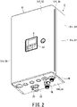
- Fig. 2 is a perspective view of the hydro unit 3 when viewed from the diagonally right front and from below.
- Fig. 3 is an exploded perspective view of the hydro unit 3 when viewed from the diagonally right front and from above.
- the hydro unit 3 of the hot water generator 1 includes a longitudinally elongated rectangular housing 51.
- the housing 51 has a front face 51f, a rear face 51r, a top face 51t, a bottom face 51b, and a pair of side faces 51s.
- the housing 51 includes: a front plate 52 that covers the front face 51f; a rear plate 53 that covers the rear face 51r, a top plate 54 that covers the top face 51t; a bottom plate 55 that covers the bottom face 51b; and a pair of side plates 56 and 57 that cover the respective side faces 51s.
- the housing 51 accommodates the expansion tank 31, the water leading pipe 32, the hot-water leading pipe 33, the hot-water supplying pipe 35, the pump 36, the water heat exchanger 15 of the refrigeration circuit 10, the first intra-hydro-unit refrigerant pipe 27, and the second intra-hydro-unit refrigerant pipe 28.
- the housing 51 further accommodates: a controller accommodation box 61 that houses the controller 5; and a controller supporting plate 62 that supports the controller accommodation box 61 inside the housing 51.
- the controller accommodation box 61 is a box that opens toward the front of the housing 51. In the controller accommodation box 61, a board on which the controller 5 is mounted is supported.
- the front plate 52 has an operation window 63 for disposing the remote controller 4.
- the back side of the front plate 52 is provided with a controller supporting plate 65 that supports the remote controller 4 disposed in the operation window 63.
- the controller supporting plate 65 has a function of a lid that covers the controller accommodation box 61.
- the front plate 52, the rear plate 53, the top plate 54, the bottom plate 55, the side plates 56 and 57, the controller accommodation box 61, the controller supporting plate 62, and the controller supporting plate 65 are processed sheet metal products.
- the water leading pipe 32, the hot-water leading pipe 33, the hot-water supplying pipe 35, the pump 36, the water heat exchanger 15 of the refrigeration circuit 10, the first intra-hydro-unit refrigerant pipe 27, and the second intra-hydro-unit refrigerant pipe 28 are disposed in the space that is sandwiched between the rear plate 53 and the controller supporting plate 62.
- the expansion tank 31 is disposed in the space that is above the controller supporting plate 62 and sandwiched between the front plate 52 and the rear plate 53.
- the rear plate 53 of the housing 51 in the hot water generator 1 supports the expansion tank 31 and the water heat exchanger 15 of the refrigeration circuit 10.
- the expansion tank 31 has a cylindrical shape in which the length L in the direction of the centerline C is larger in dimension than the diameter D.
- the expansion tank 31 is housed in the housing 51 such that the centerline C is oriented toward the pair of side faces 51s.
- the length L of the expansion tank 31 is smaller in dimension than the width of the housing 51.
- the diameter D of the expansion tank 31 is smaller in dimension than the height and the depth of the housing 51.
- the expansion tank 31 is disposed at the top of the housing 51.
- the expansion tank 31 includes a cylindrical body portion 31a and a pair of end plates 31b and 31c that close both ends of the body portion 31a.
- the expansion tank 31 is fixed to the rear plate 53 by a saddle-shaped tank fixing band 66 extending on the body portion 31a.
- the tank fixing band 66 fixes the expansion tank 31 to the rear plate 53 like a saddle band used for fixing pipes. That is, the tank fixing band 66 is bent along the body portion 31a from the upper portion to the lower portion of the body portion 31a so as to fix the expansion tank 31 to the rear plate 53 of the housing 51.
- the water leading pipe 32, the hot-water leading pipe 33, the hot-water supplying pipe 35, the pump 36, the water heat exchanger 15 of the refrigeration circuit 10, the first intra-hydro-unit refrigerant pipe 27, and the second intra-hydro-unit refrigerant pipe 28 are disposed below the expansion tank 31.
- the water heat exchanger 15 is disposed directly under the expansion tank 31 and near the side plate 56 on one of the left and right sides of the housing 51 (on the left side, in this case).
- the backup heater 67 is disposed directly under the expansion tank 31 and near the side plate 57 on the other of the left and right sides of the housing 51 (on the right side, in this case).
- the backup heater 67 is fixed to the rear plate 53. Under the circumstances where the outside temperature is so extremely low that heating the water into hot water by the refrigeration circuit 10 is difficult, the backup heater 67 is used for assisting the heating of water and for further heating the hot water that is already heated by the refrigeration circuit 10 into hotter water.
- the pump 36 is disposed below the expansion tank 31, directly in front of the backup heater 67, and on the bottom plate 55 of the housing 51. Directly below the pump 36, the hot-water pipe connection joint 48 is provided.
- the hot-water pipe connection joint 48 protrudes toward the outside of the housing 51.
- the hot-water pipe connection joint 48 protrudes downward from the bottom plate 55 so as to be exposed to the outside of the housing 51.
- the water-leading-pipe connection joint 46 is provided behind the obliquely left side of the hot-water pipe connection joint 48.
- the water leading pipe 32 connected to the water-leading-pipe connection joint 46 bends toward the water heat exchanger 15 at the portion that enters the back side of the housing 51 from the bottom plate 55 of the housing 51, extends in the vicinity of the bottom plate 55 in parallel to the bottom plate 55, and is connected to the back side of the lower end of the right side-face of the water heat exchanger 15.
- the hot-water supplying pipe 35 is connected to the back side of the upper end of the right side-face of the water heat exchanger 15.
- the hot-water supplying pipe 35 extends from the water heat exchanger 15 toward the side plate 57 of the housing 51, bends at an intermediate position between the water heat exchanger 15 and the backup heater 67 toward the bottom plate 55 of the housing 51, hangs directly downward so as to extend in parallel to the bottom plate 55 at a portion reaching the lower end of the backup heater 67, and is connected to the lower end of the left side-face of the backup heater 67.
- the hot-water leading pipe 33 branches from the hot-water supplying pipe 35 via a cross-shaped branch at the upper end of the front face of the backup heater 67, rises toward the top face plate 54 of the housing 51, reaches substantially the same height as the centerline C of the expansion tank 31, and bypasses the front of the expansion tank 31 so as to be connected to the end plate 31b on the left side of the expansion tank 31.
- the hot-water supplying pipe 35 extends downward from the cross-shaped branch so as to reach the pump 36. That is, the pump 36 is connected to the outlet end of the hot-water supplying pipe 35.
- the first intra-hydro-unit refrigerant pipe 27 and the second intra-hydro-unit refrigerant pipe 28 enter the housing 51 through a refrigerant-pipe insertion hole 71 provided on the bottom plate 55 of the housing 51.
- the first intra-hydro-unit refrigerant pipe 27 extends on the right side of the water heat exchanger 15 toward the expansion tank 31, bends toward the water heat exchanger 15 near the front of the upper end of the right side-face of the water heat exchanger 15, and is connected to the water heat exchanger 15.
- the first intra-hydro-unit refrigerant pipe 27 rises and extends almost directly in front of the hanging portion of the hot-water supplying pipe 35.
- the refrigerant pipe connection joint 25 is provided at the end of the first intra-hydro-unit refrigerant pipe 27 disposed outside the housing 51.
- the second intra-hydro-unit refrigerant pipe 28 rises in parallel to the first intra-hydro-unit refrigerant pipe 27 in the vicinity closer to the water heat exchanger 15 than the first intra-hydro-unit refrigerant pipe 27, bends toward the water heat exchanger 15 near the front of the lower end of the right side-face of the water heat exchanger 15, and is connected to the water heat exchanger 15.
- the refrigerant pipe connection joint 26 is provided at the end of the second intra-hydro-unit refrigerant pipe 28 disposed outside the housing 51.
- the pump 36 of the hot water generator 1 includes a pump-inlet pipe joint 72 and a pump-outlet pipe joint 73.
- the pump-inlet pipe joint 72 and the pump-outlet pipe joint 73 are screw-in pipe joints.
- the pump-inlet pipe joint 72 and the pump-outlet pipe joint 73 are integrated into the housing 75 of the pump 36.
- the pump-inlet pipe joint 72 and the pump-outlet pipe joint 73 are arranged substantially in a straight line with the housing 75 interposed therebetween.
- the pump 36 is housed inside the housing 51 in such a manner that the pump-inlet pipe joint 72 faces upward and the pump-outlet pipe joint 73 faces downward.
- the hot-water pipe connection joint 48 for connecting the hot-water pipe 47 outside the hydro unit 3 to the pump 36 is connected to the pump-outlet pipe joint 73.
- the second hot-water pipe connection joint 76 for connecting the hot-water supplying pipe 35 to the pump 36 is connected to the pump-inlet pipe joint 72.
- the housing 51 has a joint insertion hole 77 for projecting the hot-water pipe connection joint 48 fixed to the pump-outlet pipe joint 73 to the outside of the housing 51.
- the joint insertion hole 77 is provide on the bottom plate 55 of the housing 51.
- the hot-water pipe connection joint 48 is an adapter for connecting the hot-water pipe 47 outside the hydro unit 3 to the pump-outlet pipe joint 73 of the pump 36.
- the hot-water pipe connection joint 48 is fixed to the pump-outlet pipe joint 73 so as to be disposed outside the housing 51 through the joint insertion hole 77 of the housing 51.
- the hot-water pipe connection joint 48 is connected to the hot-water pipe 47 outside the housing 51.
- the hot-water pipe connection joint 48 has a non-circular outer shape when viewed in the direction of being connected to the pump-outlet pipe joint 73.
- the hot-water pipe connection joint 48 has an outer shape portion 48a in the shape of a hexagon nut.
- the housing 51 is provided with a loosening prevention unit 81 that is provided at the opening edge of the joint insertion hole 77 and prevents loosening of the hot-water pipe connection joint 48 fixed to the pump-outlet pipe joint 73.
- the loosening prevention unit 81 includes a plurality of anti-loosening pieces 82 (i.e., loosening prevention pieces 82) that protrude from the opening edge of the joint insertion hole 77 to the outside of the housing 51 and prevent loosening of the hot-water pipe connection joint 48 fixed to the pump-outlet pipe joint 73.
- the anti-loosening pieces 82 are provided on the respective six sides of the joint insertion hole 77 having a hexagonal hole shape so as to fit the outer shape portion 48a of the hot-water pipe connection joint 48.
- Each anti-loosening piece 82 is a cut-up formed by bending the material plate at the time of forming the joint insertion hole 77 on the bottom plate 55, which is a processed sheet metal product.
- the loosening prevention unit 81 bears the force for fastening the hot-water pipe 47 to the hot-water pipe connection joint 48 with the housing 51, and prevents the hot-water pipe connection joint 48 connected to the pump-outlet pipe joint 73 from loosening.
- the hot water generator 1 includes: an anti-loosening member 85 (i.e., loosening prevention member 85) that is fixed to the outside of the housing 51 and intervenes between the housing 51 and the hot-water pipe connection joint 48 so as to prevent loosening of the hot-water pipe connection joint 48 connected to the pump-outlet pipe joint 73; and a plurality of fastening members 86 that fix the anti-loosening member 85 to the housing 51.
- an anti-loosening member 85 i.e., loosening prevention member 85
- a plurality of fastening members 86 that fix the anti-loosening member 85 to the housing 51.
- the housing 51 includes a plurality of first fixing holes 87 that are annularly arranged to form a circle C1 centered on the joint insertion hole 77.
- the anti-loosening member 85 includes: a hexagonal fitting hole 88 into which the outer shape portion 48a of the hot-water pipe connection joint 48 can be fitted; and a plurality of second fixing holes 89 that are annularly arranged to form a circle C2 centered on the fitting hole 88 and each has an elongated hole shape along the circle C2.
- the plurality of first fixing holes 87 are annularly arranged along the circle C1 at equal intervals.
- the plurality of second fixing holes 89 are annularly arranged along the circle C2 at equal intervals.
- the number N1 of the first fixing holes 87 is larger than the number N2 of the second fixing holes 89.
- Number N 1 of first fixing holes 87 > Number N 2 of second fixing holes 89
- the combination of the number N1 of the first fixing holes 87 and the number N2 of the second fixing holes 89 is set to be continuous even numbers or continuous multiples of 3.
- this combination is set to be, for example, (10, 8), (12, 10), (14, 12), (12, 9), or (15, 12).
- first angle ⁇ 1 360 ° ⁇ number N 1 of first fixing holes
- second angle ⁇ 2 360 ° ⁇ number N 2 of second fixing holes opening range ⁇ r > second angle ⁇ 2 ⁇ first angle ⁇ 1
- the first angle ⁇ 1 represents the arranged interval (i.e., so-called pitch) of the plurality of first fixing holes 87 by an angle.
- the second angle ⁇ 2 represents the arranged interval (i.e., so-called pitch) of the plurality of second fixing holes 89 by an angle.
- each second fixing hole 89 in the direction along the circle C2 i.e., length of each second fixing hole 89, which is a slotted hole, in the longitudinal direction is not too large.
- the opening range ⁇ r and the diameter dimension of the circle C2 are appropriately set.
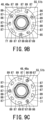
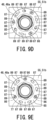
- Fig. 9A to Fig. 9G illustrate a case where the above-described relationship between the first fixing holes 87 and the second fixing holes 89 is established and the combination of the number N1 of the first fixing holes 87 and the number N2 of the second fixing holes 89 is set to (12, 9).
- the first angle ⁇ 1 is 30° and the second angle ⁇ 2 is 40°.
- the opening range ⁇ r is larger than 10°.
- the opening range ⁇ r is satisfactory if the anti-loosening member 85 can move within the calculated range "second angle ⁇ 2 - first angle ⁇ 1" when the fastening members 86 are inserted into the first fixing holes 87 of the housing 51 and are in a loose state.
- the opening range ⁇ r is satisfactory if the thickness of the fastening member 86 is added to this calculated range " ⁇ 2- ⁇ 1".
- Fig. 9A When Fig. 9A is defined as the reference position of the fastening position of the hot-water pipe connection joint 48, i.e., 0° position, Fig. 9B to Fig. 9G show the respective states where the fastening positions of the hot-water pipe connection joint 48 differ from one another by 5°. That is, Fig. 9A shows the 0-degree fastening position, Fig. 9B shows the 5° fastening position, Fig. 9C shows the 10° fastening position, Fig. 9D shows the 15° fastening position, and Fig. 9E shows the 20° fastening position, Fig. 9F shows the 25° fastening position, and Fig. 9G shows the 30° fastening position.
- any of the fastening states of Fig. 9A to Fig. 9G there are three combinations of the first fixing holes 87 and the second fixing holes 89that overlap each other so as to enable the fastening member 86 to be tightened therethrough. Since the hot-water pipe connection joint 48, which has the outer shape portion 48a in the shape of a hexagon nut, is in the same fastening state at every 30°, the anti-loosening member 85 can always be fixed to the housing 51 with three fastening members 86. The anti-loosening member 85 may be fixed to the housing 51 with two fastening members 86.
- the anti-loosening member 85 can always be fixed to the housing 51 with two fastening members 86.
- the anti-loosening member 85 bears the force for fastening the hot-water pipe 47 to the hot-water pipe connection joint 48 in cooperation with the housing 51, and thereby prevents the hot-water pipe connection joint 48 connected to the pump-outlet pipe joint 73 from loosening.
- the fitting hole 88 of the anti-loosening member 85 may be provided with anti-loosening pieces 82 as shown in Fig. 6 and Fig. 7 .
- the hot-water supplying pipe 35 of the hot water generator 1 includes a hot-water pipe outlet pipe-joint 91.
- the hot-water pipe outlet pipe-joint 91 is a screw-in pipe joint.
- the hot-water pipe outlet pipe-joint 91 is provided at the connection end of the hot-water supplying pipe 35.
- the hot-water pipe outlet pipe-joint 91 is an adapter for connecting the hot-water supplying pipe 35 to the second hot-water pipe connection joint 76.
- the hot-water pipe outlet pipe-joint 91 is interdigitated with the second hot-water pipe connection joint 76.
- a sealing material 92 such as an O-ring is sandwiched between the hot-water pipe outlet pipe-joint 91 and the second hot-water pipe connection joint 76.
- the hot-water pipe outlet pipe-joint 91 includes a first fixing flange 95.
- the second hot-water pipe connection joint 76 is an adapter for connecting the hot-water supplying pipe 35 to the pump-inlet pipe joint 72 of the pump 36.
- the second hot-water pipe connection joint 76 is a screw-in pipe joint that can be connected to the pump-inlet pipe joint 72 of the pump 36, and is also a screw-in pipe joint that can be connected to the hot-water pipe outlet pipe-joint 91 of the hot-water supplying pipe 35.
- the second hot-water pipe connection joint 76 includes a second fixing flange 96.
- the hot-water pipe outlet pipe-joint 91 and the second hot-water pipe connection joint 76 are connected by a fixture 97 and are fixed to the housing 51.
- the fixture 97 fixes the hot-water pipe outlet pipe-joint 91 and the second hot-water pipe connection joint 76 to the housing 51 via the backup heater 67 which is fixed to the housing 51. Note that the fixture 97 may be fixed directly to the housing 51.
- the fixture 97 is a saddle-shaped saddle band that is bent to cover the hot-water pipe outlet pipe-joint 91 and the second hot-water pipe connection joint 76 in the direction orthogonal to the insertion direction of the hot-water pipe outlet pipe-joint 91 and the second hot-water pipe connection joint 76.
- the fixture 97 holds the first fixing flange 95 and the second fixing flange 96 together so as to connect the screw-in pipe joints. Both ends of the fixture 97 are fixed to the backup heater 67 with fastening members 98 such as screws.
- the diameter D1 of the first fixing flange 95 (i.e., widest dimension in the polygon) and the diameter D2 of the second fixing flange 96 are larger than the arch height H of the fixture 97.
- the diameter D1 of the first fixing flange 95 and the diameter D2 of the second fixing flange 96 may be larger than the arch width W of the fixture 97.
- the diameter D1 of the first fixing flange 95 and the diameter D2 of the second fixing flange 96 may be larger than the arch height H of the fixture 97 and larger than the arch width W. In other words, it is sufficient if magnitude relationship of these dimensions satisfies one or both of Expression 3 and Expression 4 below.
- the fixture 97 has slits 99 through which the first fixing flange 95 of the hot-water pipe outlet pipe-joint 91 and the second fixing flange 96 of the second hot-water pipe connection joint 76 are inserted together. It is preferred that the width S of each slit 99 satisfies the following two conditions. Firstly, the width S of each slit 99 is larger than the sum of the thickness T1 of the first fixing flange 95 and the thickness T2 of the second fixing flange 96 such that the first fixing flange 95 and the second fixing flange 96 can be readily inserted into the slits 99.
- each slit 99 is narrow enough to reliably maintain interdigitation between the hot-water pipe outlet pipe-joint 91 and the second hot-water pipe connection joint 76 so as to prevent water leakage from the connection portion between the hot-water pipe outlet pipe-joint 91 and the second hot-water pipe connection joint 76.
- the fixture 97 can connect the first fixing flange 95 of the hot-water pipe outlet pipe-joint 91 and the second fixing flange 96 of the second hot-water pipe connection joint 76 while supporting the pump 36 to the housing 51.
- Such a fixture 97 can reduce the number of components and contribute to weight reduction and cost reduction of the hydro unit 3, as compared with the case of using a member for supporting the pump 36 to the housing 51 and another separate member for connecting the first fixing flange 95 of the hot-water pipe outlet pipe-joint 91 to the second fixing flange 96 of the second hot-water pipe connection joint 76.
- the fixture 97 may have a rectangular saddle shape as shown in Fig. 10 and Fig. 11 , a triangular saddle shape, a pentagonal or larger polygonal saddle shape, or an arcuate saddle shape.
- the slits 99 are preferably provided discretely (i.e., at intervals or discontinuously) so as to avoid vertices as shown in Fig. 10 and Fig. 11 .
- the fixture 97 can readily obtain sufficient strength for connecting the first fixing flange 95 of the hot-water pipe outlet pipe-joint 91 and the second fixing flange 96 of the second hot-water pipe connection joint 76 while supporting the pump 36.
- the slits 99 are off the center of the bandwidth of the fixture 97 that extends in a band shape.
- the fixture 97 has a narrow continuous portion 97n extending along one side of the slits 99 and a wide continuous portion 97w extending along the other side of the slits 99.
- the fixture 97 desirably connects the first fixing flange 95 of the hot-water pipe outlet pipe-joint 91 and the second fixing flange 96 of the second hot-water pipe connection joint 76 so as to support the pump 36, in a state where the narrow continuous portion 97n is disposed above the first fixing flange 95 and the second fixing flange 96 and the wide continuous portion 97w is disposed below the first fixing flange 95 and the second fixing flange 96.
- the fixture 97 configured to support the pump 36 in this manner can more reliably support the pump 36 than the case where the slits 99 are formed along the center of the bandwidth of the fixture 97. Since the fixture 97 has the wide continuous portion 97w, the fixture 97 can contribute to reduction in material cost and weight by the narrow continuous portion 97n while maintaining the same strength as a fixture in which slits are formed along the center of the bandwidth.
- the pump 36 may be supported by the housing 51 by means of the anti-loosening structure of the hot-water pipe connection joint 48 connected to the pump-outlet pipe joint 73 or may be supported by the housing 51 by means of the fixing structure of the second hot-water pipe connection joint 76 connected to the pump-inlet pipe joint 72.
- the pump 36 may be supported by the housing 51 by means of one of the anti-loosening structure of the hot-water pipe connection joint 48 and the fixing structure of the second hot-water pipe connection joint 76. It is preferred that the pump 36 is supported by the housing 51 by means of the anti-loosening structure of the hot-water pipe connection joint 48.
- the hot water generator 1 includes the hot-water pipe connection joint 48 that is fixed to the pump-outlet pipe joint 73 of the pump 36 so as to be disposed outside the housing 51 through the joint insertion hole 77 and is connectable to the hot-water pipe 47 for sending hot water to the hot water supply place.
- the hot water generator 1 can connect the hot-water pipe 47 to the hot-water pipe connection joint 48, which is fixed directly to the pump-outlet pipe joint 73 of the pump 36.
- the hot water generator 1 does not require a pipe that relays the pump 36 and the hot-water pipe connection joint 48 and/or a fixture that fixes this relay pipe to the housing, and thus, the hot water generator 1 can reduce the pressure loss of the relay pipe and contribute to miniaturization of the housing, improvement of commercial value due to the miniaturization, and cost reduction.
- the joint that may be loosened by the force for fastening the hot-water pipe 47 to the hot-water pipe connection joint 48 can be readily limited to the hot-water pipe connection joint 48, which is fixed to the pump-outlet pipe joint 73 of the pump 36. Even if the hot-water pipe connection joint 48 fixed to the pump-outlet pipe joint 73 of the pump 36 becomes loose, the looseness can be restored immediately.
- the hot water generator 1 includes the loosening prevention unit 81 that is provided on the opening edge of the joint insertion hole 77 of the housing 51 so as to prevent loosening of the hot-water pipe connection joint 48.
- the hot water generator 1 can bear the force for fastening the hot-water pipe 47 to the hot-water pipe connection joint 48 by the housing 51 and can prevent the hot-water pipe connection joint 48 connected to the pump-outlet pipe joint 73 from loosening.
- the hot water generator 1 includes the plurality of second fixing holes 89 that has the opening range ⁇ larger than the angle range obtained by subtracting the first angle ⁇ 1 from the second angle ⁇ 2, wherein the first angle ⁇ 1 is obtained by dividing 360° by the number N1 of the first fixing holes 87 and the second angle ⁇ 2 is the angle obtained by dividing 360° by the number N2 of the second fixing holes 89.
- the hot water generator 1 can bear the force for fastening the hot-water pipe 47 to the hot-water pipe connection joint 48 by the anti-loosening member 85 and the housing 51 and can prevent the hot-water pipe connection joint 48 connected to the pump-outlet pipe joint 73 from loosening.
- connection of the hot-water pipe 47 extending to the hot water supply place for supplying hot water can be achieved without loosening the pump-outlet pipe joint 73 of the pump 36 and without inducing water leakage due to the loosening of the pump-outlet pipe joint 73 of the pump 36.
Landscapes
- Engineering & Computer Science (AREA)
- Physics & Mathematics (AREA)
- Thermal Sciences (AREA)
- Chemical & Material Sciences (AREA)
- Combustion & Propulsion (AREA)
- Mechanical Engineering (AREA)
- General Engineering & Computer Science (AREA)
- Heat-Pump Type And Storage Water Heaters (AREA)
- Housings, Intake/Discharge, And Installation Of Fluid Heaters (AREA)
- Bakery Products And Manufacturing Methods Therefor (AREA)
- Thermotherapy And Cooling Therapy Devices (AREA)
- Massaging Devices (AREA)
Applications Claiming Priority (1)
| Application Number | Priority Date | Filing Date | Title |
|---|---|---|---|
| PCT/JP2020/012707 WO2021191963A1 (ja) | 2020-03-23 | 2020-03-23 | 温水生成装置 |
Publications (3)
| Publication Number | Publication Date |
|---|---|
| EP4130601A1 true EP4130601A1 (de) | 2023-02-08 |
| EP4130601A4 EP4130601A4 (de) | 2023-12-06 |
| EP4130601B1 EP4130601B1 (de) | 2026-04-29 |
Family
ID=77890017
Family Applications (1)
| Application Number | Title | Priority Date | Filing Date |
|---|---|---|---|
| EP20927547.8A Active EP4130601B1 (de) | 2020-03-23 | 2020-03-23 | Heisswassererzeugungsvorrichtung |
Country Status (4)
| Country | Link |
|---|---|
| EP (1) | EP4130601B1 (de) |
| CN (1) | CN115103984B (de) |
| AU (1) | AU2020438326B2 (de) |
| WO (1) | WO2021191963A1 (de) |
Families Citing this family (1)
| Publication number | Priority date | Publication date | Assignee | Title |
|---|---|---|---|---|
| DE102023124990A1 (de) * | 2023-09-15 | 2025-03-20 | Stiebel Eltron Gmbh & Co. Kg | Haustechnikgerät |
Family Cites Families (20)
| Publication number | Priority date | Publication date | Assignee | Title |
|---|---|---|---|---|
| GB540325A (en) * | 1941-02-10 | 1941-10-14 | John Banks Dunlop | Nut-lock |
| CH350838A (de) * | 1957-04-25 | 1960-12-15 | Schnetzler Graf Anton | Sicherungsscheibe für Schraubenverbindungen |
| DE1679792C3 (de) * | 1967-04-13 | 1973-10-31 | Joh. Vaillant Kg, 5630 Remscheid | Montagevorrichtung fur gasbe heizte Durchlauferhitzer |
| JPS5311858Y2 (de) * | 1971-10-20 | 1978-03-31 | ||
| US4529346A (en) * | 1983-07-22 | 1985-07-16 | Borg-Warner Corporation | Securing assembly for a threaded member |
| JP2605634Y2 (ja) * | 1993-06-30 | 2000-07-31 | 株式会社ガスター | 配管系の継手装置 |
| JP3026207B1 (ja) * | 1998-10-06 | 2000-03-27 | 株式会社藤井合金製作所 | ガス栓 |
| JP3263372B2 (ja) * | 1998-11-13 | 2002-03-04 | 株式会社藤井合金製作所 | 配管接続部へのフランジ板の取り付け方法及び配管接続部へのフランジ板の取り付け構造 |
| JP2001090696A (ja) | 1999-09-21 | 2001-04-03 | Sanyo Electric Co Ltd | 循環ポンプの固定構造 |
| JP3505484B2 (ja) * | 2000-08-03 | 2004-03-08 | ヤマハリビングテック株式会社 | 給湯装置用フランジ付き管継手 |
| DE102004011280A1 (de) * | 2004-03-09 | 2005-09-29 | Robert Bosch Gmbh | Anschlussvorrichtung für ein Wandheizgerät |
| US20100008743A1 (en) * | 2008-07-08 | 2010-01-14 | Gregory James Bawden | Device for Inhibiting Unfastening Rotation of Rotary Fasteners, Particularly for Vehicle Wheels |
| KR101329509B1 (ko) * | 2008-08-04 | 2013-11-13 | 엘지전자 주식회사 | 히트펌프 연동 온수 순환 시스템 및 제어 방법 |
| CN202510520U (zh) * | 2012-04-03 | 2012-10-31 | 郑书银 | 一种螺丝固定件 |
| CN103410836B (zh) * | 2013-08-12 | 2016-02-10 | 武汉万邦激光金刚石工具有限公司 | 一种用于旋转部件可快速装卸的自锁螺母 |
| JP6128331B2 (ja) * | 2014-02-26 | 2017-05-17 | 株式会社富士通ゼネラル | 温水暖房装置 |
| JP2016217417A (ja) * | 2015-05-19 | 2016-12-22 | コニカミノルタ株式会社 | 緩み止め装置及びフランジ構造体 |
| JP2017072366A (ja) * | 2016-12-08 | 2017-04-13 | 東芝キヤリア株式会社 | ねじおよびねじの製造方法 |
| EP3361182B1 (de) * | 2017-02-08 | 2020-03-25 | Grundfos Holding A/S | Hydraulische baueinheit für eine heizungs- oder klimaanlage |
| KR101990745B1 (ko) * | 2018-09-10 | 2019-06-18 | 김미영 | 원터치식 순간 온수발생장치 |
-
2020
- 2020-03-23 AU AU2020438326A patent/AU2020438326B2/en active Active
- 2020-03-23 WO PCT/JP2020/012707 patent/WO2021191963A1/ja not_active Ceased
- 2020-03-23 EP EP20927547.8A patent/EP4130601B1/de active Active
- 2020-03-23 CN CN202080096717.4A patent/CN115103984B/zh active Active
Also Published As
| Publication number | Publication date |
|---|---|
| CN115103984B (zh) | 2024-01-09 |
| EP4130601B1 (de) | 2026-04-29 |
| WO2021191963A1 (ja) | 2021-09-30 |
| CN115103984A (zh) | 2022-09-23 |
| AU2020438326A1 (en) | 2022-10-06 |
| AU2020438326B2 (en) | 2023-12-07 |
| NZ792388A (en) | 2025-05-30 |
| EP4130601A4 (de) | 2023-12-06 |
Similar Documents
| Publication | Publication Date | Title |
|---|---|---|
| CN102959353B (zh) | 带有可变形隔壁的多通道管 | |
| EP2420711A1 (de) | Ventilblock, ventilblockeinheit und verfahren zur inspektion der ventilblockeinheit | |
| EP2541171A1 (de) | Wärmetauscher mit drei flüssigkeiten und klimaanlage/wassererhitzungssystem damit | |
| EP3431897B1 (de) | Wärmepumpenvorrichtung | |
| EP3203158B1 (de) | Wärmetauscheranordnung und kühlvorrichtungsausseneinheit | |
| EP4130601B1 (de) | Heisswassererzeugungsvorrichtung | |
| KR20170090119A (ko) | 공기조화기의 열교환기 고정구조 | |
| EP2495500A2 (de) | Heißwasserversorgungssystem | |
| EP4130600B1 (de) | Vorrichtung zur erzeugung von heissem wasser | |
| EP3502576A1 (de) | Kompressoreinheit und ausseneinheit damit | |
| JP5202726B2 (ja) | 負荷側中継ユニット及びそれを搭載した空調給湯複合システム | |
| CN114938658B (zh) | 制冷循环装置的室外机 | |
| JP6104378B2 (ja) | 空気調和装置 | |
| US11248856B2 (en) | Refrigeration apparatus | |
| US10578377B2 (en) | Heat exchanger and refrigeration cycle apparatus | |
| EP3627060B1 (de) | Strömungsstörer und klimaanlage damit | |
| CN220062218U (zh) | 换热装置及空调 | |
| WO2018138906A1 (ja) | 熱交換器及びヒートポンプ給湯器 | |
| CN223283167U (zh) | 空调器 | |
| CN222123467U (zh) | 空调器 | |
| JP2025172604A (ja) | ヒートポンプ装置 | |
| KR20030042708A (ko) | 공조장치의 열교환기 | |
| KR20020042345A (ko) | 멀티 공기조화기용 튜브커넥터 | |
| KR20000007705A (ko) | 냉동시스템용 열교환기 | |
| KR20080010059A (ko) | 이중과냉각장치 및 이를 적용한 공기조화기 |
Legal Events
| Date | Code | Title | Description |
|---|---|---|---|
| STAA | Information on the status of an ep patent application or granted ep patent |
Free format text: STATUS: THE INTERNATIONAL PUBLICATION HAS BEEN MADE |
|
| PUAI | Public reference made under article 153(3) epc to a published international application that has entered the european phase |
Free format text: ORIGINAL CODE: 0009012 |
|
| STAA | Information on the status of an ep patent application or granted ep patent |
Free format text: STATUS: REQUEST FOR EXAMINATION WAS MADE |
|
| 17P | Request for examination filed |
Effective date: 20220920 |
|
| AK | Designated contracting states |
Kind code of ref document: A1 Designated state(s): AL AT BE BG CH CY CZ DE DK EE ES FI FR GB GR HR HU IE IS IT LI LT LU LV MC MK MT NL NO PL PT RO RS SE SI SK SM TR |
|
| DAV | Request for validation of the european patent (deleted) | ||
| DAX | Request for extension of the european patent (deleted) | ||
| A4 | Supplementary search report drawn up and despatched |
Effective date: 20231103 |
|
| RIC1 | Information provided on ipc code assigned before grant |
Ipc: F24H 9/14 20060101ALI20231027BHEP Ipc: F24H 9/02 20060101ALI20231027BHEP Ipc: F24H 9/12 20220101AFI20231027BHEP |
|
| GRAP | Despatch of communication of intention to grant a patent |
Free format text: ORIGINAL CODE: EPIDOSNIGR1 |
|
| STAA | Information on the status of an ep patent application or granted ep patent |
Free format text: STATUS: GRANT OF PATENT IS INTENDED |
|
| RIC1 | Information provided on ipc code assigned before grant |
Ipc: F24H 9/12 20220101AFI20251015BHEP Ipc: F24H 9/02 20060101ALI20251015BHEP Ipc: F24H 9/14 20060101ALI20251015BHEP Ipc: F24D 12/02 20060101ALI20251015BHEP Ipc: F24H 4/02 20220101ALI20251015BHEP |
|
| INTG | Intention to grant announced |
Effective date: 20251029 |
|
| GRAS | Grant fee paid |
Free format text: ORIGINAL CODE: EPIDOSNIGR3 |
|
| GRAA | (expected) grant |
Free format text: ORIGINAL CODE: 0009210 |
|
| STAA | Information on the status of an ep patent application or granted ep patent |
Free format text: STATUS: THE PATENT HAS BEEN GRANTED |
|
| RAP3 | Party data changed (applicant data changed or rights of an application transferred) |
Owner name: CARRIER JAPAN CORPORATION |
|
| AK | Designated contracting states |
Kind code of ref document: B1 Designated state(s): AL AT BE BG CH CY CZ DE DK EE ES FI FR GB GR HR HU IE IS IT LI LT LU LV MC MK MT NL NO PL PT RO RS SE SI SK SM TR |
|
| REG | Reference to a national code |
Ref country code: CH Ref legal event code: F10 Free format text: ST27 STATUS EVENT CODE: U-0-0-F10-F00 (AS PROVIDED BY THE NATIONAL OFFICE) Effective date: 20260429 |