WO2018138906A1 - 熱交換器及びヒートポンプ給湯器 - Google Patents
熱交換器及びヒートポンプ給湯器 Download PDFInfo
- Publication number
- WO2018138906A1 WO2018138906A1 PCT/JP2017/003147 JP2017003147W WO2018138906A1 WO 2018138906 A1 WO2018138906 A1 WO 2018138906A1 JP 2017003147 W JP2017003147 W JP 2017003147W WO 2018138906 A1 WO2018138906 A1 WO 2018138906A1
- Authority
- WO
- WIPO (PCT)
- Prior art keywords
- heat exchanger
- tube
- pipe
- resin member
- refrigerant
- Prior art date
Links
Images


Classifications
-
- F—MECHANICAL ENGINEERING; LIGHTING; HEATING; WEAPONS; BLASTING
- F28—HEAT EXCHANGE IN GENERAL
- F28D—HEAT-EXCHANGE APPARATUS, NOT PROVIDED FOR IN ANOTHER SUBCLASS, IN WHICH THE HEAT-EXCHANGE MEDIA DO NOT COME INTO DIRECT CONTACT
- F28D7/00—Heat-exchange apparatus having stationary tubular conduit assemblies for both heat-exchange media, the media being in contact with different sides of a conduit wall
- F28D7/10—Heat-exchange apparatus having stationary tubular conduit assemblies for both heat-exchange media, the media being in contact with different sides of a conduit wall the conduits being arranged one within the other, e.g. concentrically
- F28D7/14—Heat-exchange apparatus having stationary tubular conduit assemblies for both heat-exchange media, the media being in contact with different sides of a conduit wall the conduits being arranged one within the other, e.g. concentrically both tubes being bent
-
- F—MECHANICAL ENGINEERING; LIGHTING; HEATING; WEAPONS; BLASTING
- F28—HEAT EXCHANGE IN GENERAL
- F28D—HEAT-EXCHANGE APPARATUS, NOT PROVIDED FOR IN ANOTHER SUBCLASS, IN WHICH THE HEAT-EXCHANGE MEDIA DO NOT COME INTO DIRECT CONTACT
- F28D7/00—Heat-exchange apparatus having stationary tubular conduit assemblies for both heat-exchange media, the media being in contact with different sides of a conduit wall
- F28D7/10—Heat-exchange apparatus having stationary tubular conduit assemblies for both heat-exchange media, the media being in contact with different sides of a conduit wall the conduits being arranged one within the other, e.g. concentrically
- F28D7/106—Heat-exchange apparatus having stationary tubular conduit assemblies for both heat-exchange media, the media being in contact with different sides of a conduit wall the conduits being arranged one within the other, e.g. concentrically consisting of two coaxial conduits or modules of two coaxial conduits
-
- F—MECHANICAL ENGINEERING; LIGHTING; HEATING; WEAPONS; BLASTING
- F28—HEAT EXCHANGE IN GENERAL
- F28F—DETAILS OF HEAT-EXCHANGE AND HEAT-TRANSFER APPARATUS, OF GENERAL APPLICATION
- F28F21/00—Constructions of heat-exchange apparatus characterised by the selection of particular materials
- F28F21/06—Constructions of heat-exchange apparatus characterised by the selection of particular materials of plastics material
- F28F21/062—Constructions of heat-exchange apparatus characterised by the selection of particular materials of plastics material the heat-exchange apparatus employing tubular conduits
-
- F—MECHANICAL ENGINEERING; LIGHTING; HEATING; WEAPONS; BLASTING
- F28—HEAT EXCHANGE IN GENERAL
- F28F—DETAILS OF HEAT-EXCHANGE AND HEAT-TRANSFER APPARATUS, OF GENERAL APPLICATION
- F28F21/00—Constructions of heat-exchange apparatus characterised by the selection of particular materials
- F28F21/08—Constructions of heat-exchange apparatus characterised by the selection of particular materials of metal
- F28F21/081—Heat exchange elements made from metals or metal alloys
-
- F—MECHANICAL ENGINEERING; LIGHTING; HEATING; WEAPONS; BLASTING
- F28—HEAT EXCHANGE IN GENERAL
- F28D—HEAT-EXCHANGE APPARATUS, NOT PROVIDED FOR IN ANOTHER SUBCLASS, IN WHICH THE HEAT-EXCHANGE MEDIA DO NOT COME INTO DIRECT CONTACT
- F28D21/00—Heat-exchange apparatus not covered by any of the groups F28D1/00 - F28D20/00
- F28D2021/0019—Other heat exchangers for particular applications; Heat exchange systems not otherwise provided for
- F28D2021/0068—Other heat exchangers for particular applications; Heat exchange systems not otherwise provided for for refrigerant cycles
-
- F—MECHANICAL ENGINEERING; LIGHTING; HEATING; WEAPONS; BLASTING
- F28—HEAT EXCHANGE IN GENERAL
- F28F—DETAILS OF HEAT-EXCHANGE AND HEAT-TRANSFER APPARATUS, OF GENERAL APPLICATION
- F28F1/00—Tubular elements; Assemblies of tubular elements
- F28F1/10—Tubular elements and assemblies thereof with means for increasing heat-transfer area, e.g. with fins, with projections, with recesses
- F28F1/12—Tubular elements and assemblies thereof with means for increasing heat-transfer area, e.g. with fins, with projections, with recesses the means being only outside the tubular element
- F28F1/14—Tubular elements and assemblies thereof with means for increasing heat-transfer area, e.g. with fins, with projections, with recesses the means being only outside the tubular element and extending longitudinally
- F28F1/20—Tubular elements and assemblies thereof with means for increasing heat-transfer area, e.g. with fins, with projections, with recesses the means being only outside the tubular element and extending longitudinally the means being attachable to the element
-
- F—MECHANICAL ENGINEERING; LIGHTING; HEATING; WEAPONS; BLASTING
- F28—HEAT EXCHANGE IN GENERAL
- F28F—DETAILS OF HEAT-EXCHANGE AND HEAT-TRANSFER APPARATUS, OF GENERAL APPLICATION
- F28F2225/00—Reinforcing means
- F28F2225/04—Reinforcing means for conduits
-
- F—MECHANICAL ENGINEERING; LIGHTING; HEATING; WEAPONS; BLASTING
- F28—HEAT EXCHANGE IN GENERAL
- F28F—DETAILS OF HEAT-EXCHANGE AND HEAT-TRANSFER APPARATUS, OF GENERAL APPLICATION
- F28F2240/00—Spacing means
Definitions
- the present invention relates to a double-pipe heat exchanger in which a second pipe is provided inside a first pipe, and a heat pump water heater provided with the heat exchanger.
- a double-tube heat exchanger in which a second tube is provided inside the first tube.
- a heat exchanger there is one in which water is circulated through a first pipe and refrigerant is circulated through a second pipe so that water and the refrigerant can exchange heat.
- a heat exchanger that includes a water channel through which water flows and a refrigerant channel that is disposed in the water channel and through which a refrigerant flows, and that exchanges heat between the water and the refrigerant
- the heat exchanger is configured such that on the external appearance of the heat exchanger, the wall surface of the water channel can be seen through and the refrigerant pipe constituting the refrigerant channel can be seen.
- An exchanger has been proposed (see, for example, Patent Document 1).
- the heat exchanger described in Patent Document 1 visualizes the inside of the first tube by configuring the first tube with a resin material having transparency. Therefore, in the heat exchanger described in Patent Document 1, it is possible to check the second pipe provided inside the first pipe from the appearance of the heat exchanger, and the serviceability is improved. ing.
- the heat exchanger described in Patent Document 1 is intended to improve serviceability by making the first tube transparent with a resin material, but no consideration is given to the deformation of the first tube. . Therefore, in the double pipe heat exchanger in which the first pipe is formed of a resin material, further improvement is required in order to improve reliability.
- the present invention has been made against the background of the above-described problems, and the first tube made of resin and the second tube made of metal are made non-contact without adopting a complicated configuration.
- An object is to provide a heat exchanger and a heat pump water heater.
- a heat exchanger includes a resin-made first pipe through which a fluid flows, a metal second pipe positioned inside the first pipe and through which a refrigerant flows,
- the first tube and the second tube are formed separately from each other, and are provided in a part between the inner peripheral surface of the first tube and the outer peripheral surface of the second tube And a member.
- the heat pump water heater according to the present invention includes the above heat exchanger as a condenser.
- the heat exchanger according to the present invention is formed separately from the first tube and the second tube in a part between the inner peripheral surface of the first tube and the outer peripheral surface of the second tube. Since the resin member is provided, the first tube and the second tube can be brought into non-contact without adopting a complicated configuration.
- the heat pump water heater according to the present invention has the above-described heat exchanger, the first tube and the second tube can be brought into non-contact with the resin member, so that the deformation of the first tube can be suppressed. Reliability will be improved.
- FIG. 1 is a refrigerant circuit configuration diagram schematically showing an example of a circuit configuration of a heat pump water heater 100 according to an embodiment of the present invention.
- a heat pump water heater 100 will be described with reference to FIG.
- the heat pump water heater 100 includes a refrigerant circuit A and a fluid circuit B.
- the fluid circuit B is connected to at least one of various load sides that require hot water such as a faucet of a household water supply or a bath, and is configured to supply hot water to the load side.
- the fluid circuit B is connected to a water supply pipe (not shown) such as a water pipe, and is configured to be able to supply water via the water supply pipe.
- the refrigerant circulates in the refrigerant circuit A through the refrigerant pipe 20A.
- the refrigerant for example, carbon dioxide can be employed.
- the refrigerant circuit A includes a compressor 101 that compresses the refrigerant, a first heat exchanger 50 that functions as a condenser (gas cooler), an expansion device 102 that is an expansion device, and a second heat exchanger that functions as an evaporator. 103.
- the compressor 101 compresses the refrigerant.
- the refrigerant compressed by the compressor 101 is discharged from the compressor 101 and sent to the first heat exchanger 50.
- the compressor 101 can be composed of, for example, a rotary compressor, a scroll compressor, a screw compressor, a reciprocating compressor, or the like.
- the first heat exchanger 50 functions as a condenser, performs heat exchange between the high-temperature and high-pressure refrigerant flowing through the refrigerant circuit A and the fluid flowing through the fluid circuit B, and condenses the refrigerant.
- the first heat exchanger 50 is a double-tube heat exchanger in which the second pipe 20 is provided inside the first pipe 10. A fluid such as water is circulated through the first tube 10. A refrigerant is circulated through the second pipe 20.
- the first heat exchanger 50 corresponds to the “heat exchanger” of the present invention.
- the expansion device 102 expands and decompresses the refrigerant that has flowed out of the first heat exchanger 50.
- the expansion device 102 may be constituted by, for example, an electric expansion valve that can adjust the flow rate of the refrigerant.
- an electric expansion valve that can adjust the flow rate of the refrigerant.
- the expansion device 102 not only an electric expansion valve but also a mechanical expansion valve employing a diaphragm for a pressure receiving portion, a capillary tube, or the like can be applied.
- the second heat exchanger 103 functions as an evaporator, performs heat exchange between the low-temperature and low-pressure refrigerant that has flowed out of the expansion device 102 and the air supplied by the blower 105, and converts the low-temperature and low-pressure liquid refrigerant or two-phase refrigerant into Evaporate.
- the second heat exchanger 103 is, for example, a fin and tube heat exchanger, a microchannel heat exchanger, a shell and tube heat exchanger, a heat pipe heat exchanger, a double pipe heat exchanger, or a plate A heat exchanger or the like can be used.
- FIG. 1 shows an example in which the second heat exchanger 103 is a fin-and-tube heat exchanger that performs heat exchange between air and a refrigerant.
- the fluid circulates in the fluid circuit B through the fluid pipe 10A.
- the fluid for example, water, antifreeze, or the like can be used.
- the fluid circuit B is formed including the first heat exchanger 50 and a pump (not shown) that conveys fluid.
- the heat pump water heater 100 includes a control device 60 that performs overall control of the heat pump water heater 100. Specifically, the control device 60 controls the drive frequency of the compressor 101 according to the required hot water supply capacity. Further, the control device 60 controls the opening degree of the expansion device 102 in accordance with the operating state. Furthermore, the control device 60 controls the driving of the blower 105 and a pump (not shown) according to the operating state.
- control device 60 uses information sent from each temperature sensor (not shown) and each pressure sensor (not shown) based on an operation instruction from the user, and uses each actuator (compressor 101, throttle device 102, blower 105). , And a pump (not shown) or the like).
- the control device 60 may be provided in a unit in which the compressor 101 or the like is mounted, or may be provided in another unit.
- Each functional unit included in the control device 60 is configured by dedicated hardware or MPU (Micro Processing Unit) that executes a program stored in a memory.
- MPU Micro Processing Unit
- the heat pump water heater 100 can perform a hot water supply operation based on an instruction from the load side.
- the operation of each actuator is controlled by the control device 60.
- the low-temperature and low-pressure refrigerant is compressed by the compressor 101 and is discharged from the compressor 101 as a high-temperature and high-pressure gas refrigerant.
- the high-temperature and high-pressure gas refrigerant discharged from the compressor 101 flows into the first heat exchanger 50.
- the refrigerant flowing into the first heat exchanger 50 flows through the second pipe 20 that forms part of the refrigerant circuit A and flows through the first pipe 10 that forms part of the fluid circuit B. Heat exchange with fluid. At this time, the refrigerant is condensed and flows out of the first heat exchanger 50 as a low-temperature and high-pressure liquid refrigerant.
- the refrigerant changes in temperature while remaining in a supercritical state.
- the fluid flowing into the first pipe 10 is heated by the refrigerant flowing through the second pipe 20 and supplied to the load side.
- the low-temperature and high-pressure liquid refrigerant that has flowed out of the first heat exchanger 50 becomes low-temperature and low-pressure liquid refrigerant (or two-phase refrigerant) by the expansion device 102 and flows into the second heat exchanger 103.
- the refrigerant flowing into the second heat exchanger 103 exchanges heat with the air supplied by the blower 105 attached to the second heat exchanger 103 to become a low-temperature and low-pressure gas refrigerant. Spill from.
- the refrigerant that has flowed out of the second heat exchanger 103 is sucked into the compressor 101 again.
- FIG. 1 shows an example in which the refrigerant flow is in a certain direction in the refrigerant circuit A, but a flow path switching device is provided on the discharge side of the compressor 101 so that the refrigerant flow can be reversed. May be.
- the first heat exchanger 50 also functions as an evaporator
- the second heat exchanger 103 also functions as a condenser.
- the combination of a two-way valve, the combination of a three-way valve, or a four-way valve is employable, for example.
- carbon dioxide is desirable as a refrigerant used in the heat pump water heater 100, but is not limited to using carbon dioxide.
- carbon dioxide for example, natural refrigerants (hydrocarbon, helium, etc.), alternative refrigerants that do not contain chlorine (HFC410A, HFC407C, HFC404A, etc.), or fluorocarbon refrigerants (R22, R134a, etc.) used in existing products ) Can also be used.
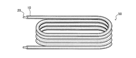
- FIG. 2 is a perspective view schematically showing an external configuration of the first heat exchanger 50.
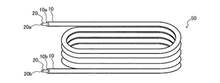
- FIG. 3 is a perspective view schematically showing the internal configuration of the first heat exchanger 50.
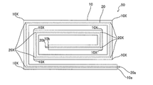
- FIG. 4 is a schematic view schematically illustrating an example of a cross-sectional configuration of the first heat exchanger 50.
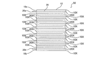
- FIG. 5 is a schematic view schematically showing an example of the configuration of the first heat exchanger 50.
- the configuration of the first heat exchanger 50 according to the embodiment of the present invention provided in the heat pump water heater 100 will be described with reference to FIGS.
- the first heat exchanger 50 includes a first pipe 10 through which a fluid flows and a second pipe 20 through which a refrigerant flows.
- the second tube 20 is provided inside the first tube 10. That is, the first heat exchanger 50 is a double-pipe heat exchanger as described above.
- the first pipe 10 is connected to the fluid pipe 10A and forms part of the fluid circuit B together with the fluid pipe 10A.
- the second pipe 20 is connected to the refrigerant pipe 20A and forms part of the refrigerant circuit A together with the refrigerant pipe 20A.
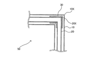
- the first heat exchanger 50 is configured by bending the first tube 10 and the second tube 20 a plurality of times. 4 and 5, the bent portion of the first tube 10 is illustrated as a bent portion 10X, and the bent portion of the second tube 20 is illustrated as a bent portion 20X.
- the first heat exchanger 50 can be configured such that a plurality of bent first and second tubes 10 and 20 are circumferentially overlapped. That is, in terms of appearance, the first heat exchanger 50 can be configured such that the first tube 10 overlaps in the vertical direction of the drawing in FIGS.
- the first heat exchanger 50 can be configured by bending the first tube 10 and the second tube 20 multiple times toward the center. That is, in appearance, the first tube 10 can be configured to be spiral from the outer side to the inner side in FIG.
- the first heat exchanger 50 can be configured by bending the first tube 10 and the second tube 20 multiple times in a zigzag manner. That is, in terms of appearance, the first tube 10 can be configured to overlap so as to meander in the vertical direction of the sheet of FIG.
- a fluid inlet 10a through which fluid flows and a fluid outlet 10b through which fluid flows out are formed at the end of the first tube 10.
- the first pipe 10 is made of a resin material and is made of resin. The resin material forming the first tube 10 will be described in detail later.
- the second tube 20 is made of a metal material such as copper or aluminum, and is made of metal.
- the fluid inlet 10a and the refrigerant inlet 20a correspond to each other
- the fluid outlet 10b and the refrigerant outlet 20b correspond to each other
- the state where the fluid and the refrigerant flow in parallel is shown as an example.
- the fluid inlet 10a and the refrigerant outlet 20b may be associated with each other
- the fluid outlet 10b and the refrigerant inlet 20a may be associated with each other so that the fluid and the refrigerant are opposed to each other.
- the first heat exchanger 50 functions as a condenser, a high-temperature refrigerant flows through the second pipe 20.
- the resin-made first tube 10 may be deformed. Therefore, the first heat exchanger 50 includes the resin member 30.
- FIG. 6 is an enlarged vertical cross-sectional view schematically showing an example of a partial cross-sectional configuration of the first heat exchanger 50.
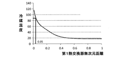
- FIG. 7 is a graph showing the refrigerant temperature distribution of the first heat exchanger 50. With reference to FIG.6 and FIG.7, the preferable installation position of the resin member 30 is demonstrated. In FIG. 7, the vertical axis represents the refrigerant temperature, and the horizontal axis represents the dimensionless number of the distance of the first heat exchanger 50.
- FIG. 6 shows an example in which the resin member 30 is installed on the inner peripheral surface of the first tube 10. Furthermore, in FIG. 6, the cross section which cut
- the resin member 30 is provided inside the first tube 10 as a separate body from the first tube 10 and the second tube 20. That is, the resin member 30 is not formed by deforming a part of the outer peripheral surface of the second tube 20 or deforming a part of the inner peripheral surface of the first tube 10.
- the resin member 30 is provided at a part between the inner peripheral surface of the first tube 10 and the outer peripheral surface of the second tube 20. That is, the resin member 30 is not provided between the inner peripheral surface of the first tube 10 and the outer peripheral surface of the second tube 20.
- the resin member 30 makes the outer peripheral surface of the second tube 20 and the inner peripheral surface of the first tube 10 non-contact. By installing the resin member 30, contact between the outer peripheral surface of the second tube 20 and the inner peripheral surface of the first tube 10 can be avoided, and the heat of the refrigerant flowing through the second tube 20 is generated by the first tube 10. Will not be transmitted to. Therefore, even when a high-temperature refrigerant flows through the second pipe 20, the heat is not transmitted to the first pipe 10, and the resin-made first pipe 10 is not deformed.
- the refrigerant When the first heat exchanger 50 functions as a condenser or a gas cooler, the refrigerant has the highest temperature at the inlet of the first heat exchanger 50. As the refrigerant proceeds through the first heat exchanger 50, the temperature gradually decreases. Then, after proceeding to a certain extent through the first heat exchanger 50, the refrigerant temperature becomes substantially constant until it flows out. Therefore, if the resin member 30 is installed in the portion where the temperature of the refrigerant flowing through the second pipe 20 is the highest, the heat of the refrigerant flowing through the second pipe 20 is transmitted to the first pipe 10. Is less likely to end up.
- the resin member 30 may be provided at least between the refrigerant inlet 20 a of the second pipe 20 and a range that is 5% or less of the entire length of the second pipe 20.
- the resin member 30 is installed in the portion where the temperature of the refrigerant flowing through the second pipe 20 is the highest, and the heat of the refrigerant flowing through the second pipe 20 is transferred to the first pipe 10. Therefore, the deformation of the first tube 10 can be suppressed. Further, the resin member 30 can be reduced.
- FIG. 8 is an enlarged vertical cross-sectional view schematically illustrating another example of a partial cross-sectional configuration including a bent portion of the first heat exchanger 50.
- FIG. 9 is an enlarged vertical cross-sectional view schematically showing still another example of a partial cross-sectional configuration including a bent portion of the first heat exchanger 50.
- FIG. 8 and 9 show an example in which the resin member 30 is installed on the inner peripheral surface of the first pipe 10. Furthermore, in FIG.8 and FIG.9, the cross section which cut
- the first tube 10 and the second tube 20 are bent a plurality of times. Therefore, in the 1st heat exchanger 50, the 1st pipe
- the resin member 30 is not only the bent portion 10 ⁇ / b> X of the first tube 10 and the bent portion 20 ⁇ / b> X of the second tube 20, but also the first tube 10 and the second tube. You may provide in 20 straight line parts. By doing so, contact between the first tube 10 and the second tube 20 can be further avoided.
- the first tube 10 and the second tube 20 are likely to come into contact with each other outside the fluid flow in the bent portion 10X and the bent portion 20X.
- a centrifugal force acts on each of the first tube 10 and the second tube 20, and the first tube 10 and the second tube. This is because each of 20 tends to deform outward. Therefore, as shown in FIG. 9, the resin member 30 may be provided at least outside the flow of fluid flowing through the first pipe 10. By doing so, contact between the first tube 10 and the second tube 20 can be avoided with a simpler configuration.
- the installation position of the resin member 30 described in FIG. 7 may be added. If it carries out like this, the contact with the 1st pipe
- the number of installed resin members 30 is not particularly limited. As the number of installed resin members 30 is smaller, the cost is reduced. When the number of installed resin members 30 is limited, as shown in FIG. 9, the resin member 30 may be provided at least outside the flow of fluid flowing through the first pipe 10. . Furthermore, the cross-sectional shape of the resin member 30 obtained by cutting the first tube 10 and the second tube 20 in the direction along the flow path is not particularly limited.
- the resin member 30 can be formed in a polygonal cross section as shown in FIGS. Alternatively, the resin member 30 may be formed in a circular cross section. Further, the resin member 30 may have a polygonal cross section and a shape obtained by rounding each corner of the polygon.
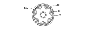
- FIG. 10 is an enlarged longitudinal sectional view schematically showing an example of a sectional configuration of the resin member 30 of the first heat exchanger 50.
- FIG. 10 the cross section which cut
- the resin member 30 can be formed to have an annular cross-sectional shape.
- the resin member 30 can be installed over the entire circumference of a part of the inner peripheral surface of the first tube 10. The installation state at this time corresponds to FIGS. 6 and 8.
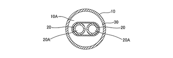
- FIG. 11 is a longitudinal sectional view schematically showing an enlarged view of another example of the sectional configuration of the resin member 30 of the first heat exchanger 50.
- tube 20 in the direction orthogonal to a flow path is shown schematically.
- the resin member 30 can be formed in a semicircular cross section.
- the resin member 30 can be installed only on the outside of a part of the inner peripheral surface of the first tube 10.
- FIG. 11 shows an example in which two second tubes 20 are provided inside the first tube 10.
- the two second tubes 20 may be provided, and the number of the second tubes 20 is not particularly limited.
- FIG. 12 is a longitudinal sectional view schematically showing an enlarged view of still another example of the sectional configuration of the resin member 30 of the first heat exchanger 50.
- FIG. 13 is an enlarged longitudinal sectional view schematically showing still another example of the sectional configuration of the resin member 30 of the first heat exchanger 50.
- FIG. 14 is an enlarged longitudinal sectional view schematically showing still another example of the sectional configuration of the resin member 30 of the first heat exchanger 50. 12 to 14 schematically show cross sections obtained by cutting the first tube 10 and the second tube 20 in a direction perpendicular to the flow path.
- the resin member 30 has an annular cross-sectional shape and has a groove 30A along the fluid flow direction. Since the resin member 30 is formed in an annular shape, the resin member 30 can be installed over the entire circumference of a part of the inner peripheral surface of the first tube 10 as in FIG. Moreover, since the resin member 30 has the groove 30 ⁇ / b> A, the fluid can be prevented from being obstructed by the resin member 30.
- the resin member 30 Since the resin member 30 is installed inside the first tube 10, it becomes a resistor against the flow of fluid. Therefore, as shown in FIGS. 12 to 14, the flow of the fluid is made smooth by forming the groove 30A in the resin member 30.
- the shape, size, and number of the grooves 30A are not particularly limited, and may be determined according to the shape, size, and number of the resin members 30. Moreover, you may make it form the groove
- the cross-sectional shape of the resin member 30 obtained by cutting the first tube 10 and the second tube 20 in a direction orthogonal to the flow path is not particularly limited.
- the resin member 30 can be formed so that the inner peripheral surface of the resin member 30 is a flat surface.
- the resin member 30 may be formed so that the cross-sectional shape of the resin member 30 is a polygonal shape.
- the resin member 30 may be formed such that the cross-sectional shape of the resin member 30 includes a circular arc shape.
- FIG. 15 is an enlarged longitudinal sectional view schematically showing still another example of a partial sectional configuration including a bent portion of the first heat exchanger 50.
- the resin member 30 will be described with reference to FIG. In FIG. 15, unlike the case shown in FIGS. 6, 8, and 9, a state where the resin member 30 is installed on the outer peripheral surface of the second pipe 20 is shown as an example.
- FIG. 15 schematically shows a cross section in which the first tube 10 and the second tube 20 are cut in a direction along the flow path.
- the case where the resin member 30 is installed on the inner peripheral surface of the first tube 10 is shown as an example.
- the case where is installed is shown as an example. That is, the resin member 30 is provided on a part between the inner peripheral surface of the first tube 10 and the outer peripheral surface of the second tube 20 by being installed on the outer peripheral surface of the second tube 20.
- the function of the resin member 30 is as described with reference to FIGS.
- the installation position of the resin member 30 is not particularly limited, the resin member 30 may be installed at a position including at least the bent portion 10X and the bent portion 20X as shown in FIG. By doing so, contact between the first tube 10 and the second tube 20 can be avoided.
- the length of the resin member 30 along the fluid flow direction is not particularly limited, as shown in FIG. 15, the length of the resin member 30 along the fluid flow direction is shown in FIGS.
- the resin member 30 may be formed longer than the resin member 30 shown in FIG. Or you may make it install the resin member 30 shown in FIG.6, FIG8 and FIG.9 in the outer peripheral surface of the 2nd pipe
- the number of installed resin members 30 is not particularly limited.
- the cross-sectional shape of the resin member 30 obtained by cutting the first tube 10 and the second tube 20 in the direction along the flow path is not particularly limited.
- the resin member 30 may be formed in a polygonal cross section as shown in FIG. 15, or may be formed including an arc shape in the cross section.
- 16 and 17 are enlarged longitudinal sectional views schematically showing an example of a sectional configuration of the resin member 30 of the first heat exchanger 50. 16 and 17 schematically show cross sections obtained by cutting the first tube 10 and the second tube 20 in a direction orthogonal to the flow path.
- the resin member 30 can be formed to have an annular cross-sectional shape.
- the resin member 30 By forming the resin member 30 to have an annular cross section, it is possible to install the resin member 30 over the entire circumference of a part of the outer peripheral surface of the second tube 20.
- the installation state of the resin member shown in FIG. 16 corresponds to FIG.
- FIG. 17 shows an example in which two second pipes 20 are provided inside the first pipe 10.
- the resin member 30 having an annular cross section may be provided on the outer periphery of each second tube 20, but as shown in FIG.
- the resin member 30 having an annular cross section may be provided on the outer periphery of the two second tubes 20 in common with the two second tubes 20.
- tube 20 is not specifically limited.
- the resin member 30 is formed using a resin having a heat resistant temperature of 100 degrees or more. If the resin member 30 is formed using a resin having a heat resistant temperature of 100 ° C. or higher, no matter what refrigerant is used in the heat pump water heater 100, the resin member 30 is caused by the heat of the refrigerant flowing into the first heat exchanger 50. Will not be deformed.
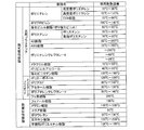
- FIG. 18 is a table showing the heat-resistant temperature of the resin.
- examples of the resin having a heat resistant temperature of 100 ° C. or higher include high-density polyethylene, polypropylene, AS resin, ABS resin, polyethylene terephthalate, vinylidene chloride resin, polycarbonate, polyamide, acetal resin, and polybutylene terephthalate. , Fluorine resin, phenol resin, melamine resin, polyurethane, epoxy resin, unsaturated polyester resin, and the like. Therefore, the resin forming the resin member 30 may be selected according to the type of refrigerant circulated in the refrigerant circuit A.
- the first heat exchanger 50 includes a resin-made first pipe 10 through which a fluid flows, and a metal second pipe 20 that is positioned inside the first pipe 10 and through which a refrigerant flows.
- the first tube 10 and the second tube 20 are formed separately from each other, and are provided in a part between the inner peripheral surface of the first tube 10 and the outer peripheral surface of the second tube 20.
- the resin member 30 is provided. Therefore, according to the first heat exchanger 50, the first pipe 10 and the second pipe 20 are formed on a part between the inner peripheral surface of the first pipe 10 and the outer peripheral surface of the second pipe 20.
- the resin member 30 formed as a separate member is provided, the first tube 10 and the second tube 20 can be brought into non-contact without adopting a complicated configuration. Moreover, according to the 1st heat exchanger 50, the 1st pipe
- the first tube 10 and the second tube 10 are not deformed without deforming the first tube 10.
- the tube 20 can be made non-contact.
- the resin member 30 is provided between the refrigerant inlet 20a of the second pipe 20 and a range that is 5% or less of the total length of the second pipe 20,
- the resin member 30 is installed at a position that is easily affected by the heat of the refrigerant, and the heat of the refrigerant flowing through the second pipe 20 can be hardly transmitted to the first pipe 10.
- the resin member 30 is formed of a resin having a heat resistant temperature of 100 degrees or more, the resin member 30 is also deformed by the heat of the refrigerant flowing into the first heat exchanger 50. There is nothing. Therefore, according to the 1st heat exchanger 50, the non-contact state of the 1st pipe
- the first tube 10 has a bent portion 10X
- the second tube 20 has a bent portion 20X
- the resin member 30 is provided in the bent portion 10X and the bent portion 20X. It has been. Therefore, according to the 1st heat exchanger 50, the resin member 30 will be installed in the location which is easy to contact, and the 1st pipe
- the resin member 30 is provided only on the outer peripheral side of the bent portion 20X of the second tube 20, contact between the first tube 10 and the second tube 20 is prevented. Furthermore, it can be avoided with a simple configuration.
- the resin member 30 is provided on the inner peripheral surface of the first pipe 10 in the first heat exchanger 50, the resin member 30 is placed inside the first pipe 10 without using a special member. Can be installed.
- the resin member 30 is provided on the outer peripheral surface of the second pipe 20, the resin member 30 is installed inside the first pipe 10 without using a special member. can do.
- the first heat exchanger 50 is provided as a condenser (gas cooler), the deformation of the first pipe 10 is suppressed and the reliability is improved. Moreover, since the resin member 30 with which the 1st heat exchanger 50 is provided is not a complicated structure, it will be produced cheaply that much.
Landscapes
- Engineering & Computer Science (AREA)
- Physics & Mathematics (AREA)
- Thermal Sciences (AREA)
- Mechanical Engineering (AREA)
- General Engineering & Computer Science (AREA)
- Heat-Exchange Devices With Radiators And Conduit Assemblies (AREA)
- Details Of Fluid Heaters (AREA)
- Heat-Pump Type And Storage Water Heaters (AREA)
Abstract
本発明に係る熱交換器は、内部を流体が流通する樹脂製の第1の管と、第1の管の内部に位置し、内部を冷媒が流通する金属製の第2の管と、第1の管及び第2の管とは別体として形成されており、第1の管の内周面と第2の管の外周面との間の一部に設けられた樹脂部材と、を備えたものである。
Description
本発明は、第1の管の内部に第2の管を設けた二重管式の熱交換器、及び、その熱交換器を備えるヒートポンプ給湯器に関するものである。
従来から、第1の管の内部に第2の管を設けた二重管式の熱交換器が存在する。このような熱交換器の一例として、第1の管に水を流通させ、第2の管に冷媒を流通させ、水と冷媒とが熱交換可能に構成されたものがある。
そのようなものとして、「内部に水が流れる水流路と前記水流路内に配設され内部に冷媒が流れる冷媒流路とからなり、前記水と前記冷媒とを熱交換する熱交換器において、前記水流路の壁面に透明性を有する樹脂材料を用いることで、熱交換器の外観上、前記水流路の壁面が透けて前記冷媒流路を構成する冷媒管が見える」ように構成された熱交換器が提案されている(例えば、特許文献1参照)。
特許文献1に記載の熱交換器は、第1の管を、透明性を有する樹脂材料で構成することで、第1の管の内部を可視化したものである。そのため、特許文献1に記載の熱交換器においては、第1の管の内部に設けた第2の管を熱交換器の外観から確認することが可能になり、サービス性が向上したものとなっている。
特許文献1に記載の熱交換器を凝縮器として用いると、冷媒配管である第2の管には高温の冷媒が流通することになる。このとき、第2の管の外周面が第1の管の内周面に接触すると、樹脂材料で形成された第1の管が、第2の管を流通する冷媒の熱によって変形してしまう可能性が生じる。また、第1の管が変形すると、第1の管に孔が形成されてしまうことも考えられる。第1の管に孔が形成されると、第1の管を流通する水が漏洩してしまい、熱交換器としての信頼性が低下する。第1の管を高耐熱性樹脂で形成することも考えられるが、高耐熱性樹脂を用いることによって第1の管に要する費用が増大してしまうことになる。
特許文献1に記載の熱交換器は、第1の管を樹脂材料により透明にしたことでサービス性の向上を図ったものであるが、第1の管の変形については何ら考慮されていなかった。そのため、第1の管を樹脂材料で形成した二重管式の熱交換器においては、信頼性を向上させるために更なる改良が求められる。
本発明は、上記のような課題を背景としてなされたものであり、樹脂製の第1の管と金属製の第2の管とを複雑な構成を採用することなく非接触とするようにした熱交換器、及び、ヒートポンプ給湯器を提供することを目的とする。
本発明に係る熱交換器は、内部を流体が流通する樹脂製の第1の管と、前記第1の管の内部に位置し、内部を冷媒が流通する金属製の第2の管と、前記第1の管及び前記第2の管とは別体として形成されており、前記第1の管の内周面と前記第2の管の外周面との間の一部に設けられた樹脂部材と、を備えたものである。
本発明に係るヒートポンプ給湯器は、上記の熱交換器を凝縮器として備えるものである。
本発明に係る熱交換器は、第1の管の内周面と第2の管の外周面との間の一部に、第1の管及び第2の管とは別体として形成された樹脂部材を設けたので、複雑な構成を採用することなく第1の管と第2の管とを非接触にすることができる。
本発明に係るヒートポンプ給湯器は、上記の熱交換器を有しているので、樹脂部材によって第1の管と第2の管とを非接触にできるので、第1の管の変形を抑制でき、信頼性が向上したものとなる。
以下、本発明に係る熱交換器及びヒートポンプ給湯器について、図面を用いて説明する。
なお、以下で説明する構成、動作等は、一例にすぎず、本発明に係る熱交換器及びヒートポンプ給湯器は、そのような構成、動作等である場合に限定されない。また、各図において、同一又は類似するものには、同一の符号を付すか、又は、符号を付すことを省略している。また、細かい構造については、適宜図示を簡略化又は省略している。また、重複又は類似する説明については、適宜簡略化又は省略している。
なお、以下で説明する構成、動作等は、一例にすぎず、本発明に係る熱交換器及びヒートポンプ給湯器は、そのような構成、動作等である場合に限定されない。また、各図において、同一又は類似するものには、同一の符号を付すか、又は、符号を付すことを省略している。また、細かい構造については、適宜図示を簡略化又は省略している。また、重複又は類似する説明については、適宜簡略化又は省略している。
図1は、本発明の実施の形態に係るヒートポンプ給湯器100の回路構成の一例を概略的に示す冷媒回路構成図である。図1を参照してヒートポンプ給湯器100について説明する。
<ヒートポンプ給湯器100の構成>
ヒートポンプ給湯器100は、冷媒回路Aと、流体回路Bと、を有している。なお、流体回路Bは、例えば、家庭の水道の蛇口、お風呂等のお湯が必要となる各種の負荷側の少なくとも1つに接続され、負荷側にお湯を供給するように構成されている。また、流体回路Bは、水道の配管等の図示省略の給水管に接続され、給水管を介して給水可能に構成されている。
ヒートポンプ給湯器100は、冷媒回路Aと、流体回路Bと、を有している。なお、流体回路Bは、例えば、家庭の水道の蛇口、お風呂等のお湯が必要となる各種の負荷側の少なくとも1つに接続され、負荷側にお湯を供給するように構成されている。また、流体回路Bは、水道の配管等の図示省略の給水管に接続され、給水管を介して給水可能に構成されている。
冷媒回路Aには冷媒配管20Aを介して冷媒が循環する。冷媒としては、例えば、二酸化炭素を採用することができる。冷媒回路Aは、冷媒を圧縮する圧縮機101と、凝縮器(ガスクーラー)として機能する第1熱交換器50と、絞り装置である絞り装置102と、蒸発器として機能する第2熱交換器103とを含んで形成される。
圧縮機101は、冷媒を圧縮するものである。圧縮機101で圧縮された冷媒は、圧縮機101から吐出されて第1熱交換器50へ送られる。圧縮機101は、例えば、ロータリ圧縮機、スクロール圧縮機、スクリュー圧縮機、往復圧縮機等で構成することができる。
第1熱交換器50は、凝縮器として機能し、冷媒回路Aを流れる高温高圧の冷媒と、流体回路Bを流れる流体とで熱交換を行い、冷媒を凝縮させるものである。後段で詳述するが、第1熱交換器50は、第1の管10の内部に、第2の管20を設けた二重管式の熱交換器である。なお、第1の管10には水などの流体が流通される。また、第2の管20には冷媒が流通される。
第1熱交換器50が、本発明の「熱交換器」に相当する。
第1熱交換器50が、本発明の「熱交換器」に相当する。
絞り装置102は、第1熱交換器50から流出した冷媒を膨張させて減圧するものである。絞り装置102は、例えば冷媒の流量を調整可能な電動膨張弁等で構成するとよい。なお、絞り装置102としては、電動膨張弁だけでなく、受圧部にダイアフラムを採用した機械式膨張弁、または、キャピラリーチューブ等を適用することも可能である。
第2熱交換器103は、蒸発器として機能し、絞り装置102から流出された低温低圧の冷媒と送風機105により供給される空気とで熱交換を行い、低温低圧の液冷媒または二相冷媒を蒸発させるものである。第2熱交換器103は、例えば、フィン・アンド・チューブ型熱交換器、マイクロチャネル熱交換器、シェルアンドチューブ式熱交換器、ヒートパイプ式熱交換器、二重管式熱交換器、プレート熱交換器等で構成することができる。図1では、第2熱交換器103が空気と冷媒とで熱交換を行うフィン・アンド・チューブ型熱交換器である場合を例に示している。
流体回路Bには流体配管10Aを介して流体が循環する。流体としては、例えば、水、不凍液等を採用することができる。流体回路Bは、第1熱交換器50と、流体を搬送する図示省略のポンプとを含んで形成される。
また、ヒートポンプ給湯器100は、ヒートポンプ給湯器100の全体を統括制御する制御装置60を備えている。具体的には、制御装置60は、必要とする給湯能力に応じて圧縮機101の駆動周波数を制御する。また、制御装置60は、運転状態に応じて絞り装置102の開度を制御する。さらに、制御装置60は、送風機105、図示省略のポンプの駆動を運転状態に応じて制御する。
つまり、制御装置60は、ユーザーからの運転指示に基づいて、図示省略の各温度センサーや図示省略の各圧力センサーから送られる情報を利用し、各アクチュエーター(圧縮機101、絞り装置102、送風機105、及び、図示省略のポンプ等)を制御するようになっている。なお、制御装置60は、圧縮機101等が搭載されたユニット内に備えてもよいし、別のユニットに備えてもよい。
制御装置60に含まれる各機能部は、専用のハードウェア、又は、メモリに格納されるプログラムを実行するMPU(Micro Processing Unit)で構成される。
<ヒートポンプ給湯器100の動作>
次に、ヒートポンプ給湯器100の動作について説明する。
ヒートポンプ給湯器100は、負荷側からの指示に基づいて、給湯運転が可能になっている。
なお、各アクチュエーターの動作は、制御装置60により制御される。
次に、ヒートポンプ給湯器100の動作について説明する。
ヒートポンプ給湯器100は、負荷側からの指示に基づいて、給湯運転が可能になっている。
なお、各アクチュエーターの動作は、制御装置60により制御される。
低温低圧の冷媒が圧縮機101によって圧縮され、高温高圧のガス冷媒となって圧縮機101から吐出される。圧縮機101から吐出された高温高圧のガス冷媒は、第1熱交換器50に流入する。第1熱交換器50に流入した冷媒は、冷媒回路Aの一部を形成している第2の管20を流通し、流体回路Bの一部を形成している第1の管10を流れる流体と熱交換される。このとき冷媒は凝縮されて低温高圧の液冷媒となって第1熱交換器50から流出する。なお、二酸化炭素を冷媒として使用した場合、冷媒は超臨界状態のまま、温度変化することになる。
一方、第1の管10に流入した流体は、第2の管20を流れる冷媒により加温され、負荷側に供給されることになる。
一方、第1の管10に流入した流体は、第2の管20を流れる冷媒により加温され、負荷側に供給されることになる。
第1熱交換器50から流出した低温高圧の液冷媒は、絞り装置102によって低温低圧の液冷媒(又は二相冷媒)となり、第2熱交換器103に流入する。第2熱交換器103に流入した冷媒は、第2熱交換器103に付設されている送風機105により供給される空気と熱交換して、低温低圧のガス冷媒となって第2熱交換器103から流出する。第2熱交換器103から流出した冷媒は、圧縮機101へ再度吸入される。
なお、図1では、冷媒回路Aにおいて冷媒の流れが一定方向となる場合を例に示しているが、圧縮機101の吐出側に流路切替装置を設けて、冷媒の流れを反転可能に構成してもよい。流路切替装置を設けた場合、第1熱交換器50は蒸発器としても機能することになり、第2熱交換器103は凝縮器としても機能することになる。なお、流路切替装置としては、例えば、二方弁の組み合わせ、三方弁の組み合わせ、又は、四方弁を採用することができる。
また、ヒートポンプ給湯器100に使用する冷媒としては二酸化炭素が望ましいが、二酸化炭素を用いることに限定するものではない。二酸化炭素の他にも、例えば自然冷媒(炭化水素、ヘリウムなど)、塩素を含まない代替冷媒(HFC410A、HFC407C、HFC404Aなど)、もしくは既存の製品に使用されているフロン系冷媒(R22、R134aなど)の冷媒も使用可能である。
[第1熱交換器50の詳細説明]
図2は、第1熱交換器50の外観構成を概略的に示す斜視図である。図3は、第1熱交換器50の内部構成を概略的に示す透視斜視図である。図4は、第1熱交換器50の断面構成の一例を概略的に示す概略図である。図5は、第1熱交換器50の構成の一例を概略的に示す概略図である。図2~図5を参照してヒートポンプ給湯器100が備える本発明の実施の形態に係る第1熱交換器50の構成について説明する。
図2は、第1熱交換器50の外観構成を概略的に示す斜視図である。図3は、第1熱交換器50の内部構成を概略的に示す透視斜視図である。図4は、第1熱交換器50の断面構成の一例を概略的に示す概略図である。図5は、第1熱交換器50の構成の一例を概略的に示す概略図である。図2~図5を参照してヒートポンプ給湯器100が備える本発明の実施の形態に係る第1熱交換器50の構成について説明する。
第1熱交換器50は、流体が流れる第1の管10と、冷媒が流れる第2の管20と、を備えている。第2の管20は、第1の管10の内部に設けられている。つまり、第1熱交換器50は、上述したように二重管式の熱交換器である。第1の管10は、流体配管10Aと接続され、流体配管10Aとともに流体回路Bの一部を形成するものである。第2の管20は、冷媒配管20Aと接続され、冷媒配管20Aとともに冷媒回路Aの一部を形成するものである。
図2~図5に示すように第1熱交換器50は、第1の管10及び第2の管20が複数回折り曲げられて構成されている。なお、図4及び図5では、第1の管10の折り曲げられた部分を折り曲げ部分10Xとして図示し、第2の管20の折り曲げられた部分を折り曲げ部分20Xとして図示している。
例えば、第1熱交換器50は、図2及び図3に示すように、複数回折り曲げた第1の管10及び第2の管20を周状に重なるように構成することができる。つまり、外観的には、図2及び図3の紙面上下方向に第1の管10が重なるように第1熱交換器50を構成することができる。
例えばまた、第1熱交換器50は、図4に示すように、第1の管10及び第2の管20を中心部に向かって複数回折り曲げて構成することができる。つまり、外観的には、図4の紙面外側から内側に向けて第1の管10が渦巻き状となるように構成することができる。
例えばまた、第1熱交換器50は、図5に示すように、第1の管10及び第2の管20をジグザグに複数回折り曲げて構成することができる。つまり、外観的には、図5の紙面上下方向に第1の管10を蛇行させるように重ねて構成することができる。
第1の管10の端部には、流体が流入される流体入口10a及び流体が流出される流体出口10bが形成されている。第1の管10は、樹脂材料により作製されたものであり、樹脂製である。なお、第1の管10を形成する樹脂材料については後段で詳述する。
第2の管20の端部には、冷媒が流入される冷媒入口20a及び冷媒が流出される冷媒出口20bが形成されている。第2の管20は、銅又はアルミニウムなどの金属材料により作製されたものであり、金属製である。
第2の管20の端部には、冷媒が流入される冷媒入口20a及び冷媒が流出される冷媒出口20bが形成されている。第2の管20は、銅又はアルミニウムなどの金属材料により作製されたものであり、金属製である。
なお、図2~図5では、流体入口10aと冷媒入口20aとを対応させ、流体出口10bと冷媒出口20bとを対応させて、流体と冷媒とが並行して流れる状態を例に示している。ただし、流体入口10aと冷媒出口20bとを対応させ、流体出口10bと冷媒入口20aとを対応させて、流体と冷媒とが対向流となるように構成してもよい。
第1熱交換器50は、凝縮器として機能するため、第2の管20には高温の冷媒が流通する。第2の管20の外周面が第1の管10の内周面に接触すると、樹脂製の第1の管10が変形してしまいかねない。そこで、第1熱交換器50は、樹脂部材30を備えている。
図6は、第1熱交換器50の一部の断面構成の一例を拡大して概略的に示す縦断面図である。図7は、第1熱交換器50の冷媒温度分布を示すグラフである。図6及び図7を参照して樹脂部材30の好ましい設置位置について説明する。図7では、縦軸に冷媒温度を、横軸に第1熱交換器50の距離の無次元数を、それぞれ示している。
なお、図6では、第1の管10における流体の流れを実線矢印で、第2の管20における冷媒の流れを破線矢印で、それぞれ表している。また、図6では、樹脂部材30が第1の管10の内周面に設置された状態を例に示している。さらに、図6では、第1の管10及び第2の管20を流路に沿った方向で切った断面を概略的に示している。
樹脂部材30は、第1の管10及び第2の管20とは別体として第1の管10の内部に設けられている。つまり、樹脂部材30は、第2の管20の外周面の一部を変形させたり、第1の管10の内周面の一部を変形させたりすることで形成されたものではない。また、樹脂部材30は、第1の管10の内周面と第2の管20の外周面との間の一部に設けられている。つまり、樹脂部材30は、第1の管10の内周面と第2の管20の外周面との間の全部に設けられたものではない。
樹脂部材30は、第2の管20の外周面と第1の管10の内周面とを非接触とするものである。樹脂部材30を設置することにより、第2の管20の外周面と第1の管10の内周面との接触が回避でき、第2の管20を流れる冷媒の熱が第1の管10に伝達されることがない。そのため、第2の管20に高温の冷媒が流れても、その熱が第1の管10に伝達されることがなく、樹脂製の第1の管10が変形することがない。
第1熱交換器50が凝縮器又はガスクーラーとして機能している場合、冷媒は、第1熱交換器50の入口で最も高い温度となる。冷媒は、第1熱交換器50を進むにつれて、徐々に温度が下がって行く。そして、第1熱交換器50をある程度進むと、冷媒温度は流出するまでほぼ一定の状態となる。そのため、第2の管20を流れる冷媒の温度が最も高い状態となっている部分に樹脂部材30を設置すれば、第2の管20を流れる冷媒の熱が第1の管10に伝達してしまう可能性が低くなる。
そこで、図7に示すように、樹脂部材30を、第2の管20の冷媒入口20aから第2の管20の全長の5%以下となる範囲までの間に少なくとも設けるとよい。これにより、第2の管20を流れる冷媒の温度が最も高い状態となっている部分に樹脂部材30が設置されることになり、第2の管20を流れる冷媒の熱が第1の管10に伝達されにくくなり、第1の管10の変形が抑制できることになる。また、樹脂部材30の低減も可能になる。
次に、樹脂部材30の設置位置の別の例について説明する。
図8は、第1熱交換器50の折り曲げ部分を含む一部の断面構成の他の一例を拡大して概略的に示す縦断面図である。図9は、第1熱交換器50の折り曲げ部分を含む一部の断面構成の更に他の一例を拡大して概略的に示す縦断面図である。図8及び図9を参照して樹脂部材30の具体的な設置位置について説明する。
図8は、第1熱交換器50の折り曲げ部分を含む一部の断面構成の他の一例を拡大して概略的に示す縦断面図である。図9は、第1熱交換器50の折り曲げ部分を含む一部の断面構成の更に他の一例を拡大して概略的に示す縦断面図である。図8及び図9を参照して樹脂部材30の具体的な設置位置について説明する。
なお、図8及び図9では、樹脂部材30が第1の管10の内周面に設置された状態を例に示している。さらに、図8及び図9では、第1の管10及び第2の管20を流路に沿った方向で切った断面を概略的に示している。
図2~図5に示したように、第1熱交換器50は、第1の管10及び第2の管20が複数回折り曲げられている。そのため、第1熱交換器50では、第1の管10の折り曲げ部分10X及び第2の管20の折り曲げ部分20Xにおいて、第1の管10と第2の管20とが接触しやすい。そこで、樹脂部材30の設置位置を特に限定するものではないが、図8及び図9に示すように、樹脂部材30を、少なくとも折り曲げ部分10X及び折り曲げ部分20Xに設置するとよい。
ただし、図8及び図9に示すように、樹脂部材30を、第1の管10の折り曲げ部分10X及び第2の管20の折り曲げ部分20Xだけでなく、第1の管10及び第2の管20の直線部分に設けてもよい。こうすることで、更に第1の管10と第2の管20との接触を回避できる。
また、第1熱交換器50においては、折り曲げ部分10X及び折り曲げ部分20Xの流体の流れの外側で第1の管10と第2の管20とが接触しやすい。折り曲げ部分10Xを流体が流れる際、及び、折り曲げ部分20Xを冷媒が流れる際に、第1の管10及び第2の管20のそれぞれに遠心力が働き、第1の管10及び第2の管20のそれぞれが外側に変形しようとするからである。そこで、図9に示すように、樹脂部材30を、少なくとも第1の管10を流通する流体の流れの外側に設けるとよい。こうすることで、第1の管10と第2の管20との接触を更に簡易な構成で回避できる。
なお、図8及び図9で説明した樹脂部材30の設置位置に加えて、図7で説明した樹脂部材30の設置位置を追加してもよい。こうすれば、熱の影響が大きい部位における第1の管10と第2の管20との接触を簡易な構成で回避できることになる。
なお、樹脂部材30の設置個数を特に限定するものではない。樹脂部材30の設置個数が少ないほど、費用が低減されることになる。また、樹脂部材30の設置個数が限定されているような場合には、図9に示すように、樹脂部材30を、少なくとも第1の管10を流通する流体の流れの外側に設ければよい。さらに、第1の管10及び第2の管20を流路に沿った方向で切った樹脂部材30の断面形状を特に限定するものではない。例えば、樹脂部材30を、図6、図8及び図9に示すように断面多角形状に形成することができる。あるいは、樹脂部材30を、断面円形状として形成してもよい。また、樹脂部材30を、断面多角形状として、多角形のそれぞれの角部を丸めた形状としてもよい。
次に、樹脂部材30の形状について説明する。
図10は、第1熱交換器50の樹脂部材30の断面構成の一例を拡大して概略的に示す縦断面図である。図10では、第1の管10及び第2の管20を流路と直交する方向で切った断面を概略的に示している。
図10は、第1熱交換器50の樹脂部材30の断面構成の一例を拡大して概略的に示す縦断面図である。図10では、第1の管10及び第2の管20を流路と直交する方向で切った断面を概略的に示している。
図10に示すように、樹脂部材30は、断面形状を円環状として形成することができる。樹脂部材30を断面円環状に形成することで、樹脂部材30を第1の管10の内周面の一部の全周に渡って設置することが可能になる。このときの設置状態は、図6及び図8に対応している。
図11は、第1熱交換器50の樹脂部材30の断面構成の他の一例を拡大して概略的に示す縦断面図である。図11では、第1の管10及び第2の管20を流路と直交する方向で切った断面を概略的に示している。
図11に示すように、樹脂部材30は、断面形状を半円環状として形成することができる。樹脂部材30を断面半円環状に形成することで、樹脂部材30を第1の管10の内周面の一部の外側にのみ設置することが可能になる。このときの設置状態は、図9に対応している。
なお、図11では、2本の第2の管20が第1の管10の内部に設けられている場合を例に示している。このように、2本の第2の管20を設けるようにしてもよく、第2の管20の本数を特に限定するものではない。
なお、図11では、2本の第2の管20が第1の管10の内部に設けられている場合を例に示している。このように、2本の第2の管20を設けるようにしてもよく、第2の管20の本数を特に限定するものではない。
図12は、第1熱交換器50の樹脂部材30の断面構成の更に他の一例を拡大して概略的に示す縦断面図である。図13は、第1熱交換器50の樹脂部材30の断面構成の更に他の一例を拡大して概略的に示す縦断面図である。図14は、第1熱交換器50の樹脂部材30の断面構成の更に他の一例を拡大して概略的に示す縦断面図である。図12~図14では、第1の管10及び第2の管20を流路と直交する方向で切った断面を概略的に示している。
図12~図14に示すように、樹脂部材30は、断面形状が円環状であり、流体の流れ方向に沿った溝30Aを有している。樹脂部材30を円環状に形成しているため、図10と同様に、樹脂部材30を第1の管10の内周面の一部の全周に渡って設置することが可能になる。また、樹脂部材30は溝30Aを有しているため、流体が樹脂部材30によって妨げられてしまうことを抑制できる。
樹脂部材30は、第1の管10の内部に設置されるため、流体の流れに対しては抵抗体となってしまう。そこで、図12~図14に示すように、樹脂部材30に溝30Aを形成することで、流体の流れを円滑にしている。
なお、溝30Aの形状、大きさ、個数を特に限定するものではなく、樹脂部材30の形状、大きさ、個数に応じて決定すればよい。また、複数の樹脂部材30を、それぞれ間隔を空けて周状に設けることで溝30Aを形成するようにしてもよい。この場合、樹脂部材30は、円環状とはならない。
なお、溝30Aの形状、大きさ、個数を特に限定するものではなく、樹脂部材30の形状、大きさ、個数に応じて決定すればよい。また、複数の樹脂部材30を、それぞれ間隔を空けて周状に設けることで溝30Aを形成するようにしてもよい。この場合、樹脂部材30は、円環状とはならない。
また、第1の管10及び第2の管20を流路と直交する方向で切った樹脂部材30の断面形状を特に限定するものではない。例えば、図10及び図11に示すように、樹脂部材30の内周面が平面となるように樹脂部材30を形成することができる。あるいは、図12及び図13に示すように、樹脂部材30の断面形状が多角形状となるように樹脂部材30を形成してもよい。また、図14に示すように、樹脂部材30の断面形状を円弧形状が含まれる形状として樹脂部材30を形成してもよい。
図15は、第1熱交換器50の折り曲げ部分を含む一部の断面構成の更に他の一例を拡大して概略的に示す縦断面図である。図15を参照して樹脂部材30について説明する。なお、図15では、図6、図8及び図9で示した場合とは異なり、樹脂部材30が第2の管20の外周面に設置された状態を例に示している。また、図15では、第1の管10及び第2の管20を流路に沿った方向で切った断面を概略的に示している。
図6、図8及び図9では、第1の管10の内周面に樹脂部材30を設置した場合を例に示したが、図15では、第2の管20の外周面に樹脂部材30を設置した場合を例に示している。すなわち、樹脂部材30は、第2の管20の外周面に設置されることで、第1の管10の内周面と第2の管20の外周面との間の一部に設けられる。なお、樹脂部材30の機能については、図6~図9で説明した通りである。
樹脂部材30の設置位置を特に限定するものではないが、図15に示すように、樹脂部材30を、少なくとも折り曲げ部分10X及び折り曲げ部分20Xを含んだ位置に設置するとよい。こうすることで、第1の管10と第2の管20との接触を回避できる。
なお、樹脂部材30の流体の流れ方向に沿った長さを特に限定するものではないが、図15に示すように樹脂部材30の流体の流れ方向に沿った長さを図6、図8及び図9に示す樹脂部材30よりも長くして樹脂部材30を形成してもよい。あるいは、図6、図8及び図9で示した樹脂部材30を、第2の管20の外周面に設置するようにしてもよい。
また、樹脂部材30の設置個数を特に限定するものではない。さらに、第1の管10及び第2の管20を流路に沿った方向で切った樹脂部材30の断面形状を特に限定するものではない。例えば、樹脂部材30を、図15に示すように断面多角形状に形成してもよいし、断面に円弧形状を含めて形成してもよい。
また、樹脂部材30の設置個数を特に限定するものではない。さらに、第1の管10及び第2の管20を流路に沿った方向で切った樹脂部材30の断面形状を特に限定するものではない。例えば、樹脂部材30を、図15に示すように断面多角形状に形成してもよいし、断面に円弧形状を含めて形成してもよい。
次に、樹脂部材30の形状について説明する。
図16及び図17は、第1熱交換器50の樹脂部材30の断面構成の一例を拡大して概略的に示す縦断面図である。図16及び図17では、第1の管10及び第2の管20を流路と直交する方向で切った断面を概略的に示している。
図16及び図17は、第1熱交換器50の樹脂部材30の断面構成の一例を拡大して概略的に示す縦断面図である。図16及び図17では、第1の管10及び第2の管20を流路と直交する方向で切った断面を概略的に示している。
図16及び図17に示すように、樹脂部材30は、断面形状を円環状として形成することができる。樹脂部材30を断面円環状に形成することで、樹脂部材30を第2の管20の外周面の一部の全周に渡って設置することが可能になる。図16に示す樹脂部材の設置状態は、図15に対応している。
なお、図17では、2本の第2の管20が第1の管10の内部に設けられている場合を例に示している。このように、2本の第2の管20を設けた場合には、断面円環状の樹脂部材30をそれぞれの第2の管20の外周に設けてもよいが、図17に示すように、断面円環状の樹脂部材30を2本の第2の管20に共通して2本の第2の管20の外周に設けてもよい。なお、第2の管20の本数を特に限定するものではない。
[第1の管10を形成する樹脂材料]
樹脂部材30は、耐熱温度が100度以上の樹脂を用いて形成するものとする。耐熱温度が100度以上の樹脂を用いて樹脂部材30を形成すれば、ヒートポンプ給湯器100にどのような冷媒を用いたとしても、第1熱交換器50に流入する冷媒の熱によって樹脂部材30が変形することがない。
樹脂部材30は、耐熱温度が100度以上の樹脂を用いて形成するものとする。耐熱温度が100度以上の樹脂を用いて樹脂部材30を形成すれば、ヒートポンプ給湯器100にどのような冷媒を用いたとしても、第1熱交換器50に流入する冷媒の熱によって樹脂部材30が変形することがない。
図18は、樹脂の耐熱温度を示す表である。図18に示すように、耐熱温度が100度以上となる樹脂としては、例えば、高密度ポリエチレン、ポリプロピレン、AS樹脂、ABS樹脂、ポリエチレンテレフタレート、塩化ビニリデン樹脂、ポリカーボネート、ポリアミド、アセタール樹脂、ポリブチレンテレフタレート、フッ素樹脂、フェノール樹脂、メラミン樹脂、ポリウレタン、エポキシ樹脂、不飽和ポリエステル樹脂などがある。したがって、冷媒回路Aに循環させる冷媒の種類に応じて、樹脂部材30を形成する樹脂を選定するとよい。
[第1熱交換器50又はヒートポンプ給湯器100が奏する効果]
第1熱交換器50は、内部を流体が流通する樹脂製の第1の管10と、第1の管10の内部に位置し、内部を冷媒が流通する金属製の第2の管20と、第1の管10及び第2の管20とは別体として形成されており、第1の管10の内周面と第2の管20の外周面との間の一部に設けられた樹脂部材30と、を備えたものである。
そのため、第1熱交換器50によれば、第1の管10の内周面と第2の管20の外周面との間の一部に、第1の管10及び第2の管20とは別体として形成された樹脂部材30を設けたので、複雑な構成を採用することなく第1の管10と第2の管20とを非接触にすることができる。また、第1熱交換器50によれば、複雑な構成を採用する場合に比較して安価に第1の管10と第2の管20とを非接触にできる。
第1熱交換器50によれば、樹脂部材30が、第1の管10とは異なる樹脂で形成されているので、第1の管10を変形することなく、第1の管10と第2の管20とを非接触にすることができる。
第1熱交換器50によれば、樹脂部材30が、第2の管20の冷媒入口20aから、第2の管20の全長の5%以下となる範囲までの間に設けられているので、冷媒の熱によって影響を受けやすい位置に樹脂部材30が設置されることになり、第2の管20を流れる冷媒の熱を第1の管10に伝達されにくくできる。
第1熱交換器50によれば、樹脂部材30が、耐熱温度が100度以上の樹脂で形成されているので、第1熱交換器50に流入する冷媒の熱によっても樹脂部材30が変形することがない。よって、第1熱交換器50によれば、第1の管10と第2の管20との非接触状態を長期間にわたって維持できることになる。
第1熱交換器50は、第1の管10が折り曲げ部分10Xを有し、第2の管20が折り曲げ部分20Xを有しており、樹脂部材30が、折り曲げ部分10X及び折り曲げ部分20Xに設けられている。そのため、第1熱交換器50によれば、接触しやすい箇所に樹脂部材30を設置することとなり、第1の管10と第2の管20とを効果的に非接触にすることができる。
第1熱交換器50によれば、樹脂部材30が、第2の管20の折り曲げ部分20Xの外周側にのみ設けられているので、第1の管10と第2の管20との接触を更に簡易な構成で回避できる。
第1熱交換器50は、樹脂部材30が、第1の管10の内周面に設けられているので、特別な部材などを用いることなく、樹脂部材30を第1の管10の内部に設置することができる。
第1熱交換器50は、樹脂部材30が、第2の管20の外周面に設けられているので、特別な部材などを用いることなく、樹脂部材30を第1の管10の内部に設置することができる。
第1熱交換器50によれば、樹脂部材30には、流体の流れ方向に沿った溝30Aが少なくとも一部に形成されているので、樹脂部材30を設置したことによる圧力損失を低減でき、流体の流れが円滑化される。
ヒートポンプ給湯器100によれば、第1熱交換器50を凝縮器(ガスクーラー)として備えているので、第1の管10の変形が抑制され、信頼性が向上したものとなる。また、第1熱交換器50が備える樹脂部材30が複雑な構成ではないため、その分安価に作成されることになる。
以上、本発明の特徴を実施の形態として説明したが、具体的な構成は、説明した実施の形態に限られるものではなく、発明の要旨を逸脱しない範囲で変更可能である。
10 第1の管、10A 流体配管、10X 折り曲げ部分、10a 流体入口、10b 流体出口、20 第2の管、20A 冷媒配管、20X 折り曲げ部分、20a 冷媒入口、20b 冷媒出口、30 樹脂部材、30A 溝、50 第1熱交換器、60 制御装置、100 ヒートポンプ給湯器、101 圧縮機、102 絞り装置、103 第2熱交換器、105 送風機、A 冷媒回路、B 流体回路。
Claims (10)
- 内部を流体が流通する樹脂製の第1の管と、
前記第1の管の内部に位置し、内部を冷媒が流通する金属製の第2の管と、
前記第1の管及び前記第2の管とは別体として形成されており、前記第1の管の内周面と前記第2の管の外周面との間の一部に設けられた樹脂部材と、を備えた
熱交換器。 - 前記樹脂部材は、
前記第1の管とは異なる樹脂で形成されている
請求項1に記載の熱交換器。 - 前記樹脂部材は、
前記第2の管の冷媒入口から、前記第2の管の全長の5%以下となる範囲までの間に設けられている
請求項1又は2に記載の熱交換器。 - 前記樹脂部材は、
耐熱温度が100度以上の樹脂で形成されている
請求項1~3のいずれか一項に記載の熱交換器。 - 前記第1の管及び前記第2の管は、折り曲げ部分を有しており、
前記樹脂部材は、
前記折り曲げ部分に設けられている
請求項1~4のいずれか一項に記載の熱交換器。 - 前記樹脂部材は、
前記第2の管の前記折り曲げ部分の外周側にのみ設けられている
請求項5に記載の熱交換器。 - 前記樹脂部材は、
前記第1の管の内周面に設けられている
請求項1~6のいずれか一項に記載の熱交換器。 - 前記樹脂部材は、
前記第2の管の外周面に設けられている
請求項1~6のいずれか一項に記載の熱交換器。 - 前記樹脂部材は、
流体の流れ方向に沿った溝が少なくとも一部に形成されている
請求項1~8のいずれか一項に記載の熱交換器。 - 請求項1~9のいずれか一項に記載の熱交換器を凝縮器として備える
ヒートポンプ給湯器。
Priority Applications (3)
| Application Number | Priority Date | Filing Date | Title |
|---|---|---|---|
| EP17894252.0A EP3575724B1 (en) | 2017-01-30 | 2017-01-30 | Heat exchanger and heat pump water heater |
| PCT/JP2017/003147 WO2018138906A1 (ja) | 2017-01-30 | 2017-01-30 | 熱交換器及びヒートポンプ給湯器 |
| JP2018564070A JP6790129B2 (ja) | 2017-01-30 | 2017-01-30 | 熱交換器及びヒートポンプ給湯器 |
Applications Claiming Priority (1)
| Application Number | Priority Date | Filing Date | Title |
|---|---|---|---|
| PCT/JP2017/003147 WO2018138906A1 (ja) | 2017-01-30 | 2017-01-30 | 熱交換器及びヒートポンプ給湯器 |
Publications (1)
| Publication Number | Publication Date |
|---|---|
| WO2018138906A1 true WO2018138906A1 (ja) | 2018-08-02 |
Family
ID=62978512
Family Applications (1)
| Application Number | Title | Priority Date | Filing Date |
|---|---|---|---|
| PCT/JP2017/003147 WO2018138906A1 (ja) | 2017-01-30 | 2017-01-30 | 熱交換器及びヒートポンプ給湯器 |
Country Status (3)
| Country | Link |
|---|---|
| EP (1) | EP3575724B1 (ja) |
| JP (1) | JP6790129B2 (ja) |
| WO (1) | WO2018138906A1 (ja) |
Cited By (1)
| Publication number | Priority date | Publication date | Assignee | Title |
|---|---|---|---|---|
| JP2022040512A (ja) * | 2020-08-31 | 2022-03-11 | ジオシステム株式会社 | 熱交換装置 |
Citations (6)
| Publication number | Priority date | Publication date | Assignee | Title |
|---|---|---|---|---|
| JPS5760192A (en) * | 1980-09-26 | 1982-04-10 | Ishida Sangyo Kk | Heat exchanger |
| JPS58198688A (ja) * | 1982-05-14 | 1983-11-18 | Matsushita Electric Ind Co Ltd | 熱交換器 |
| JPS6422173U (ja) * | 1987-07-30 | 1989-02-03 | ||
| JPH03238128A (ja) * | 1990-02-14 | 1991-10-23 | Shinko Metal Prod Kk | 熱交換器及びその製造方法 |
| JP2012092962A (ja) * | 2010-09-27 | 2012-05-17 | Sekisui Chem Co Ltd | 断熱二重管 |
| JP2013011387A (ja) | 2011-06-29 | 2013-01-17 | Panasonic Corp | 熱交換器 |
Family Cites Families (4)
| Publication number | Priority date | Publication date | Assignee | Title |
|---|---|---|---|---|
| DE3017574C2 (de) * | 1980-05-08 | 1985-06-05 | Wieland-Werke Ag, 7900 Ulm | Abstandshalter für koaxiale Wärmeübertrager |
| US4786088A (en) * | 1987-06-25 | 1988-11-22 | Asahi/America, Inc. | Double-containment thermoplastic pipe assembly |
| FR2953917B1 (fr) * | 2009-12-10 | 2012-01-20 | Hutchinson | Echangeur thermique interne pour circuit de climatisation de vehicule automobile et un tel circuit |
| CN201697503U (zh) * | 2010-02-01 | 2011-01-05 | 上海醇华电子有限公司 | 一种套管式换热器 |
-
2017
- 2017-01-30 WO PCT/JP2017/003147 patent/WO2018138906A1/ja unknown
- 2017-01-30 EP EP17894252.0A patent/EP3575724B1/en active Active
- 2017-01-30 JP JP2018564070A patent/JP6790129B2/ja active Active
Patent Citations (6)
| Publication number | Priority date | Publication date | Assignee | Title |
|---|---|---|---|---|
| JPS5760192A (en) * | 1980-09-26 | 1982-04-10 | Ishida Sangyo Kk | Heat exchanger |
| JPS58198688A (ja) * | 1982-05-14 | 1983-11-18 | Matsushita Electric Ind Co Ltd | 熱交換器 |
| JPS6422173U (ja) * | 1987-07-30 | 1989-02-03 | ||
| JPH03238128A (ja) * | 1990-02-14 | 1991-10-23 | Shinko Metal Prod Kk | 熱交換器及びその製造方法 |
| JP2012092962A (ja) * | 2010-09-27 | 2012-05-17 | Sekisui Chem Co Ltd | 断熱二重管 |
| JP2013011387A (ja) | 2011-06-29 | 2013-01-17 | Panasonic Corp | 熱交換器 |
Cited By (2)
| Publication number | Priority date | Publication date | Assignee | Title |
|---|---|---|---|---|
| JP2022040512A (ja) * | 2020-08-31 | 2022-03-11 | ジオシステム株式会社 | 熱交換装置 |
| JP7170011B2 (ja) | 2020-08-31 | 2022-11-11 | ジオシステム株式会社 | 熱交換装置 |
Also Published As
| Publication number | Publication date |
|---|---|
| EP3575724A1 (en) | 2019-12-04 |
| JPWO2018138906A1 (ja) | 2019-11-07 |
| EP3575724A4 (en) | 2020-01-08 |
| JP6790129B2 (ja) | 2020-11-25 |
| EP3575724B1 (en) | 2021-08-18 |
Similar Documents
| Publication | Publication Date | Title |
|---|---|---|
| JP2006162238A (ja) | 二重管 | |
| JP6687022B2 (ja) | 冷凍サイクル装置 | |
| EP1947405A1 (en) | Air conditioner | |
| JP5936785B1 (ja) | 空気調和装置 | |
| JP2008069993A (ja) | 熱交換器およびそれを用いたヒートポンプ給湯装置 | |
| JP6573210B2 (ja) | 二重管式熱交換器及びこれを備えたヒートポンプ式熱源機 | |
| WO2018138906A1 (ja) | 熱交換器及びヒートポンプ給湯器 | |
| JP2010038429A (ja) | 熱交換器 | |
| JP5929012B2 (ja) | 熱交換器及びヒートポンプ給湯装置 | |
| EP2796822A1 (en) | Air conditioner | |
| JP3966260B2 (ja) | ヒートポンプ給湯機 | |
| JP2006207936A (ja) | 熱交換器 | |
| JP2010255856A (ja) | 熱交換器およびそれを用いたヒートポンプ給湯機 | |
| JP2010014312A (ja) | 二重管式過冷却器 | |
| US20210278137A1 (en) | System and Method for Manufacturing and Operating a Coaxial Tube Heat Exchanger | |
| JP6563115B2 (ja) | 熱交換器及び冷凍サイクル装置 | |
| JP2009264643A (ja) | 熱交換器 | |
| JP2007333319A (ja) | 熱交換器 | |
| CN110892223B (zh) | 热交换器及制冷循环装置 | |
| JP2010255857A (ja) | 熱交換器およびそれを用いたヒートポンプ給湯機 | |
| JP2010261680A (ja) | 二重管式熱交換器 | |
| JP2022008718A (ja) | 熱交換用二重管 | |
| JP2010032183A (ja) | 熱交換器 | |
| CN112119271B (zh) | 制冷循环装置 | |
| AU2017442329B2 (en) | Heat exchanger, refrigeration cycle apparatus and method of manufacturing heat exchanger |
Legal Events
| Date | Code | Title | Description |
|---|---|---|---|
| 121 | Ep: the epo has been informed by wipo that ep was designated in this application |
Ref document number: 17894252 Country of ref document: EP Kind code of ref document: A1 |
|
| ENP | Entry into the national phase |
Ref document number: 2018564070 Country of ref document: JP Kind code of ref document: A |
|
| NENP | Non-entry into the national phase |
Ref country code: DE |
|
| ENP | Entry into the national phase |
Ref document number: 2017894252 Country of ref document: EP Effective date: 20190830 |