EP4129767A1 - Montageteil, bordvorrichtung und montageverfahren - Google Patents
Montageteil, bordvorrichtung und montageverfahren Download PDFInfo
- Publication number
- EP4129767A1 EP4129767A1 EP21774619.7A EP21774619A EP4129767A1 EP 4129767 A1 EP4129767 A1 EP 4129767A1 EP 21774619 A EP21774619 A EP 21774619A EP 4129767 A1 EP4129767 A1 EP 4129767A1
- Authority
- EP
- European Patent Office
- Prior art keywords
- attachment
- fastening portion
- fastening
- deformable member
- detent
- Prior art date
- Legal status (The legal status is an assumption and is not a legal conclusion. Google has not performed a legal analysis and makes no representation as to the accuracy of the status listed.)
- Withdrawn
Links
- 238000000034 method Methods 0.000 title claims description 23
- 210000000078 claw Anatomy 0.000 claims abstract description 55
- 238000003780 insertion Methods 0.000 claims description 14
- 230000037431 insertion Effects 0.000 claims description 14
- 230000002093 peripheral effect Effects 0.000 description 9
- 239000002184 metal Substances 0.000 description 5
- 229910052751 metal Inorganic materials 0.000 description 5
- 239000000463 material Substances 0.000 description 3
- 239000011347 resin Substances 0.000 description 3
- 229920005989 resin Polymers 0.000 description 3
- 238000003466 welding Methods 0.000 description 3
- 230000000694 effects Effects 0.000 description 2
- 150000002739 metals Chemical class 0.000 description 2
- 238000012986 modification Methods 0.000 description 2
- 230000004048 modification Effects 0.000 description 2
- 239000000758 substrate Substances 0.000 description 2
- 238000006467 substitution reaction Methods 0.000 description 1
Images






Classifications
-
- F—MECHANICAL ENGINEERING; LIGHTING; HEATING; WEAPONS; BLASTING
- F16—ENGINEERING ELEMENTS AND UNITS; GENERAL MEASURES FOR PRODUCING AND MAINTAINING EFFECTIVE FUNCTIONING OF MACHINES OR INSTALLATIONS; THERMAL INSULATION IN GENERAL
- F16B—DEVICES FOR FASTENING OR SECURING CONSTRUCTIONAL ELEMENTS OR MACHINE PARTS TOGETHER, e.g. NAILS, BOLTS, CIRCLIPS, CLAMPS, CLIPS OR WEDGES; JOINTS OR JOINTING
- F16B39/00—Locking of screws, bolts or nuts
- F16B39/22—Locking of screws, bolts or nuts in which the locking takes place during screwing down or tightening
- F16B39/24—Locking of screws, bolts or nuts in which the locking takes place during screwing down or tightening by means of washers, spring washers, or resilient plates that lock against the object
-
- F—MECHANICAL ENGINEERING; LIGHTING; HEATING; WEAPONS; BLASTING
- F16—ENGINEERING ELEMENTS AND UNITS; GENERAL MEASURES FOR PRODUCING AND MAINTAINING EFFECTIVE FUNCTIONING OF MACHINES OR INSTALLATIONS; THERMAL INSULATION IN GENERAL
- F16B—DEVICES FOR FASTENING OR SECURING CONSTRUCTIONAL ELEMENTS OR MACHINE PARTS TOGETHER, e.g. NAILS, BOLTS, CIRCLIPS, CLAMPS, CLIPS OR WEDGES; JOINTS OR JOINTING
- F16B5/00—Joining sheets or plates, e.g. panels, to one another or to strips or bars parallel to them
- F16B5/02—Joining sheets or plates, e.g. panels, to one another or to strips or bars parallel to them by means of fastening members using screw-thread
-
- F—MECHANICAL ENGINEERING; LIGHTING; HEATING; WEAPONS; BLASTING
- F16—ENGINEERING ELEMENTS AND UNITS; GENERAL MEASURES FOR PRODUCING AND MAINTAINING EFFECTIVE FUNCTIONING OF MACHINES OR INSTALLATIONS; THERMAL INSULATION IN GENERAL
- F16B—DEVICES FOR FASTENING OR SECURING CONSTRUCTIONAL ELEMENTS OR MACHINE PARTS TOGETHER, e.g. NAILS, BOLTS, CIRCLIPS, CLAMPS, CLIPS OR WEDGES; JOINTS OR JOINTING
- F16B37/00—Nuts or like thread-engaging members
- F16B37/04—Devices for fastening nuts to surfaces, e.g. sheets, plates
- F16B37/041—Releasable devices
- F16B37/043—Releasable devices with snap action
-
- H—ELECTRICITY
- H01—ELECTRIC ELEMENTS
- H01Q—ANTENNAS, i.e. RADIO AERIALS
- H01Q1/00—Details of, or arrangements associated with, antennas
- H01Q1/12—Supports; Mounting means
- H01Q1/1207—Supports; Mounting means for fastening a rigid aerial element
- H01Q1/1221—Supports; Mounting means for fastening a rigid aerial element onto a wall
-
- H—ELECTRICITY
- H01—ELECTRIC ELEMENTS
- H01Q—ANTENNAS, i.e. RADIO AERIALS
- H01Q1/00—Details of, or arrangements associated with, antennas
- H01Q1/27—Adaptation for use in or on movable bodies
- H01Q1/32—Adaptation for use in or on road or rail vehicles
- H01Q1/325—Adaptation for use in or on road or rail vehicles characterised by the location of the antenna on the vehicle
- H01Q1/3275—Adaptation for use in or on road or rail vehicles characterised by the location of the antenna on the vehicle mounted on a horizontal surface of the vehicle, e.g. on roof, hood, trunk
-
- F—MECHANICAL ENGINEERING; LIGHTING; HEATING; WEAPONS; BLASTING
- F16—ENGINEERING ELEMENTS AND UNITS; GENERAL MEASURES FOR PRODUCING AND MAINTAINING EFFECTIVE FUNCTIONING OF MACHINES OR INSTALLATIONS; THERMAL INSULATION IN GENERAL
- F16B—DEVICES FOR FASTENING OR SECURING CONSTRUCTIONAL ELEMENTS OR MACHINE PARTS TOGETHER, e.g. NAILS, BOLTS, CIRCLIPS, CLAMPS, CLIPS OR WEDGES; JOINTS OR JOINTING
- F16B35/00—Screw-bolts; Stay-bolts; Screw-threaded studs; Screws; Set screws
- F16B35/04—Screw-bolts; Stay-bolts; Screw-threaded studs; Screws; Set screws with specially-shaped head or shaft in order to fix the bolt on or in an object
- F16B35/041—Specially-shaped shafts
Definitions
- the present invention relates to an attachment portion or the like.
- Patent Literature 1 An antenna attachment device has been proposed as in Patent Literature 1.
- Patent Literature 1 JP 2007-177986 A
- an example of an object of the present invention is to facilitate attachment to an attachment object such as a vehicle.
- An attachment portion includes a first fastening portion, a second fastening portion to be screwed with the first fastening portion, a detent portion provided between the first fastening portion and the second fastening portion, and a deformable member provided between the first fastening portion and the detent portion.
- the detent portion suppresses that at least one of the first fastening portion and the deformable member rotate(s) when the second fastening portion rotates.
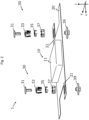
- a device for vehicle 1 of the first embodiment is an antenna device for vehicle. As illustrated in Fig. 1 and Fig. 2 , the device for vehicle 1 includes an electronic equipment 10, a holding plate (an electronic equipment holding portion) 20, and an attachment portion 30. The electronic equipment 10 is held by the holding plate 20. The holding plate 20 is held by a bracket 80 of a vehicle roof 70 via the attachment portion 30.
- a front-rear direction of the vehicle to which the device for vehicle 1 is to be attached will be described as an x direction
- a left-right direction perpendicular to the x direction will be described as a y direction
- a substantially vertical direction perpendicular to the x direction and the y direction will be described as a z direction.
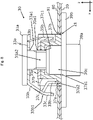
- FIG. 11 illustrate a side surface of a member constituting a first fastening portion 31 such as a head portion 31a and a member constituting a second fastening portion 39 such as a grip portion 39a, a cross-section of the holding plate 20, a member constituting a claw washer 33 such as a first flat portion 33a, a member constituting a connection portion 35 such as a second flat portion 35a, a member constituting a holder 37 such as a third flat portion 37a, and a member constituting the bracket 80 such as an in-vehicle antenna device contact portion 80c.
- the electronic equipment 10 is an antenna unit of the antenna device for vehicle.
- the electronic equipment 10 includes a case 11. Between the case 11 and the holding plate 20, electronic components such as an antenna element and a substrate for the electronic equipment 10 to function as an antenna are provided (not illustrated).
- the holding plate 20 is constituted with a metal plate and is electrically connected to a substrate of the electronic equipment 10 for grounding.
- the holding plate 20 includes a first attachment hole 21.
- the first attachment hole 21 is provided at a position facing a second attachment hole 81 which will be described later, in the z direction, when the device for vehicle 1 is attached to the bracket 80.
- the xy cross-section of the first attachment hole 21 has a cross-sectional shape other than a perfect circle, such as a polygon and an ellipse so that the third flat portion 37a fitted into the first attachment hole 21 does not rotate around an axis parallel to the z direction.
- the xy cross-section of the first attachment hole 21 has a quadrangular shape.
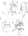
- the attachment portion 30 includes the first fastening portion 31, the claw washer (deformable member) 33, the connection portion 35, the holder 37, and the second fastening portion 39.
- the connection portion 35 and the holder 37 function as a detent portion that suppresses rotation of at least one of the first fastening portion 31 and the claw washer 33 when the second fastening portion 39 rotates.
- the first fastening portion 31 is a bolt and includes the head portion 31a and a first shaft portion 31b.
- the first shaft portion 31b is provided with a region (a first engagement portion 31c) recessed from the side surface of the first shaft portion 31b.
- the first engagement portion 31c is formed such that any of the regions in the z direction where the first engagement portion 31c of the first shaft portion 31b is provided is engaged with a second engagement portion 35a2 of a second flat portion hole 35a1 of the second flat portion 35a of the connection portion 35 at the time of screwing.
- the first engagement portion 31c is constituted with a recess having a substantially rectangular parallelepiped shape extending in the z direction.
- two first engagement portions 31c are provided so as to face each other in the y direction.
- only one first engagement portion 31c may be provided, or three or more first engagement portions 31c may be provided.
- the claw washer 33 includes the first flat portion 33a, a first leg portion 33b, and a claw portion 33c.
- the first flat portion 33a has a substantially disk shape and has a first flat portion hole 33a1 in the vicinity of the center.
- the first flat portion hole 33a1 is constituted with a round hole through which the first shaft portion 31b of the first fastening portion 31 passes.
- An upper surface of the first flat portion 33a faces a lower surface of the head portion 31a of the first fastening portion 31 at the time of assembling the attachment portion 30.
- the first leg portion 33b extends downward in the z direction from a peripheral portion of the first flat portion 33a.
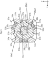
- three first leg portions 33b are provided at equal intervals in the peripheral portion of the first flat portion 33a when viewed from the z direction.
- a lower end of the first leg portion 33b is inserted into a recess (a leg receiving portion 37a2) provided on an upper surface of the third flat portion 37a of the holder 37 at the time of assembling the attachment portion 30.
- the first leg portion 33b When a force for vertically sandwiching the first leg portion 33b is applied, the first leg portion 33b is deformed so as to be bent outward in a radial direction of the first shaft portion 31b at a bent portion 33b1 in the vicinity of the center in the z direction.
- the claw portion 33c extends downward in the z direction from an upper portion of the first leg portion 33b.
- the claw portion 33c does not bend from the upper portion of the first leg portion 33b and protrudes radially outward of the first shaft portion 31b, and a lower end portion of the claw portion 33c bites into an upper surface of the bracket 80.
- connection portion 35 includes the second flat portion 35a and a second leg portion 35b.
- the second flat portion 35a has a substantially disk shape and has the second flat portion hole 35a1 in the vicinity of the center.
- the second flat portion hole 35a1 is penetrated by the first shaft portion 31b of the first fastening portion 31 and is engaged with the first engagement portion 31c of the first fastening portion 31, at the time of assembling the attachment portion 30.
- the second flat portion hole 35a1 has a shape in which the second engagement portion 35a2 is provided in the round hole.
- two second engagement portions 35a2 are provided so as to face each other in the y direction in accordance with the first engagement portion 31c.
- the second leg portion 35b extends downward in the z direction from the peripheral portion of the second flat portion 35a.
- three second leg portions 35b are provided at equal intervals in the peripheral portion of the second flat portion 35a when viewed from the z direction.
- the second leg portion 35b is disposed so as to be positioned between two adjacent first leg portions 33b as viewed from the z direction.
- the holder 37 has the third flat portion 37a, a third leg portion 37b, and a protruding portion 37c.
- the holder 37 holds the claw washer 33 and the connection portion 35.
- the third flat portion 37a has a substantially quadrangular plate shape and is fitted into the first attachment hole 21 and the second attachment hole 81 when the device for vehicle 1 is attached to the bracket 80.
- the xy cross-section of the third flat portion 37a has substantially the same size and substantially the same outer shape as the xy cross-section of an inner wall of the first attachment hole 21 and the second attachment hole 81 which will be described later.
- a third flat portion hole 37a1 is provided in the vicinity of the center of the third flat portion 37a.
- a first bearing portion 39c of the second fastening portion 39 which will be described later is inserted into the third flat portion hole 37a1.
- the third leg portion 37b extends upward in the z direction from the peripheral portion of the third flat portion 37a.
- six third leg portions 37b are provided. Further, at the time of assembling the attachment portion 30, the third leg portion 37b is disposed so as to be positioned between the adjacent first leg portion 33b and second leg portion 35b when viewed from the z direction.
- the protruding portion 37c extending upward in the z direction is provided on a peripheral edge of the third flat portion hole 37a1.
- the protruding portion 37c has a hollow cylindrical shape and has a lower surface opened.
- a third protruding portion hole 37c1 is provided on an upper surface of the protruding portion 37c.
- the third protruding portion hole 37c1 is constituted with a round hole through which the first shaft portion 31b of the first fastening portion 31 passes.
- the second fastening portion 39 is a nut and includes the grip portion 39a, a flange portion 39b, and the first bearing portion 39c.
- the grip portion 39a is a portion that is rotated directly or indirectly using a tool by a worker for attachment, or the like, so as to be screwed with the first fastening portion 31.
- the flange portion 39b is provided between the grip portion 39a and the first bearing portion 39c and has an xy cross-section larger than that of the grip portion 39a, the first attachment hole 21, and the second attachment hole 81.
- the flange portion 39b comes into contact with a lower surface of the holding plate 20 when the device for vehicle 1 is attached to the bracket 80 and functions as a stopper so that the attachment portion 30 is not excessively inserted into the first attachment hole 21.
- the flange portion 39b and the claw portion 33c of the claw washer 33 sandwich the holding plate 20 and the bracket 80.
- the first bearing portion 39c is inserted into a recess portion of the protruding portion 37c of the holder 37, and a first screw hole 39c1 into which the first shaft portion 31b of the first fastening portion 31 is to be inserted is provided near the center of an xy plane.
- the first screw hole 39c1 may be provided only in the first bearing portion 39c or may be provided continuously in the flange portion 39b and the grip portion 39a.
- the holder 37 may be constituted with a resin.
- the holding plate 20, the vehicle roof 70, and the bracket 80 are constituted with metals.
- the holding plate 20 and the attachment portion 30 may be constituted with a resin.
- the bracket 80 is a metal plate provided on a vehicle interior side of the vehicle roof 70 and includes a vehicle contact portion 80a, an arm portion 80b, and the in-vehicle antenna device contact portion 80c (see Fig. 1 ). Two brackets 80 are provided, one for holding a front side of the holding plate 20 in the x direction and the other for holding a rear side of the holding plate 20 in the x direction.
- the vehicle contact portion 80a comes into contact with the vehicle roof 70.
- the arm portion 80b extends obliquely downward from the vehicle contact portion 80a.
- the in-vehicle antenna device contact portion 80c extends in a horizontal direction from a lower end of the arm portion 80b and is constituted with a surface substantially perpendicular to the z direction.
- the holding plate 20 is attached to the in-vehicle antenna device contact portion 80c via the attachment portion 30.
- One set of the arm portion 80b and the in-vehicle antenna device contact portion 80c is provided on each of a right side in the y direction and a left side in the y direction for one bracket 80.
- the xy cross-section of the second attachment hole 81 has a cross-sectional shape other than a perfect circle, such as a polygon and an ellipse so that the fitted third flat portion 37a does not rotate about an axis parallel to the z direction.
- a perfect circle such as a polygon and an ellipse
- the xy cross-section of the second attachment hole 81 has a quadrangular shape having substantially the same size as the xy cross-section of the first attachment hole 81 and the xy cross-section of an outer shape of the third flat portion 37a.
- no attachment hole is provided in the other of the in-vehicle antenna device contact portions 80c.
- the other of the in-vehicle antenna device contact portions 80c may be provided with an attachment hole for clipping the holding plate 20 and the in-vehicle antenna device contact portion 80c.
- an attachment hole for clipping is also provided in the holding plate 20.
- the electronic equipment 10 is assembled in advance and attached to the holding plate 20.
- the attachment portion 30 is assembled in advance. Assembling the attachment portion 30 is performed as follows.
- the connection portion 35 is sandwiched between the claw washer 33 and the holder 37.
- a lower end of the first leg portion 33b of the claw washer 33 is fitted into the leg receiving portion 37a2 of the holder 37.
- the first fastening portion 31 and the second fastening portion 39 sandwich them in above mentioned state.
- the first fastening portion 31 is attached to the second fastening portion 39 by screwing.
- the worker for attachment holds the holding plate 20 and brings the holding plate 20 close to the bracket 80 from below in the z direction such that the first attachment hole 21 of the holding plate 20 and the second attachment hole 81 of the bracket 80 face each other in the z direction.
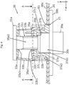
- the worker for attachment inserts the attachment portion 30 into the first attachment hole 21 and the second attachment hole 81 from below in the z direction while holding the holding plate 20 from below in the z direction (insertion step, see Fig. 4 to Fig. 7 ).
- a region including the first fastening portion 31, the claw washer 33, the connection portion 35, the holder 37, and the first bearing portion 39c of the attachment portion 30 is inserted into the first attachment hole 21 and the second attachment hole 81 from below in the z direction (from one side of the bracket 80). With such insertion, the first fastening portion 31 and the claw washer 33 are positioned on the other side of the bracket 80. In a case where the holding plate 20 and the bracket 80 are provided with the attachment holes for clipping, clipping is performed before the insertion step.
- the worker for attachment rotates the grip portion 39a of the second fastening portion 39 in a fastening direction from below in the z direction (from one side of the bracket 80) to bring the first fastening portion 31 and the second fastening portion 39 close to each other (first rotation step, see Fig. 8 to Fig. 10 ).
- the first engagement portion 31c of the first fastening portion 31 is engaged with the second engagement portion 35a2 of the connection portion 35.
- the second leg portion 35b of the connection portion 35 and the third leg portion 37b of the holder 37 are engaged with each other.
- the third flat portion 37a of the holder 37 is fitted into the first attachment hole 21 and the second attachment hole 81.
- the connection portion 35 and the holder 37 function as the detent portion of the first fastening portion 31 and the rotation of the first fastening portion 31 together with the grip portion 39a is suppressed in a case where the grip portion 39a of the second fastening portion 39 is rotated in the fastening direction. In other words, the second fastening portion 39 is rotated in a state where the first fastening portion 31 does not rotate.
- the first fastening portion 31 is moved downward in the z direction.
- a force for sandwiching the first leg portion 33b of the claw washer 33 sandwiched between the first fastening portion 31 and the holder 37 in the vertical direction is applied.
- the claw washer 33 is bent at the bent portion 33b1.
- the claw portion 33c protrudes radially outward of the first shaft portion 31b and is brought close to an upper surface of the bracket 80.
- the worker for attachment further rotates the grip portion 39a of the second fastening portion 39 in the fastening direction from below in the z direction (from one side of the bracket 80) to bring the first fastening portion 31 and the second fastening portion 39 closer (second rotation step, see Fig. 11 to Fig. 13 ).
- second rotation step see Fig. 11 to Fig. 13 .
- the rotation step will be described separately as the first rotation step and the second rotation step, but in an actual operation process, the first rotation step and the second rotation step are continuously performed.
- the first fastening portion 31 is further moved downward in the z direction, and the lower end portion of the claw portion 33c bites into the upper surface of the bracket 80.
- the first fastening portion 31 rotates along with the rotation of the second fastening portion 39 when the device for vehicle 1 is attached to the bracket 80, by engagement between the first engagement portion 31c of the first fastening portion 31 and the second engagement portion 35a2 of the connection portion 35, fitting between the first leg portion 33b of the claw washer 33 and the third leg portion 37b of the holder 37, fitting between the second leg portion 35b of the connection portion 35 and the third leg portion 37b of the holder 37, fitting between the third flat portion 37a of the holder 37 and the first attachment hole 21, and fitting between the third flat portion 37a of the holder 37 and the second attachment hole 81.
- the second fastening portion 39 is screwed with the first fastening portion 31 whose rotation is suppressed by the detent portion (the connection portion 35, the holder 37), or the like.
- the claw washer 33 is deformed, and sandwiches the holding plate 20 and the bracket 80 with the second fastening portion 39.
- the attachment portion 30 is fixed to the bracket 80.
- inserting the first fastening portion 31 or the like and rotating (fastening) the second fastening portion 39 can be performed from one side of the bracket 80. This can improve workability of attachment as compared with a mode in which the insertion step and the rotation step are performed from both sides.
- the attachment portion 30 can be easily attached to an attachment object.
- the first engagement portion 31c is constituted so as to be recessed from the side surface of the first shaft portion 31b, and the second engagement portion 35a2 is constituted so as to protrude radially inward of the first shaft portion 31b from the peripheral edge of the round hole of the second flat portion hole 35a1.
- the first engagement portion 31c may be constituted so as to protrude from the side surface of the first shaft portion 31b, and the second engagement portion 35a2 may be constituted so as to be recessed radially outward of the first shaft portion 31b from the peripheral edge of the round hole of the second flat portion hole 35a1.
- the first flat portion hole 33a1 of the claw washer 33 is also provided with an engagement portion that engages with the first engagement portion 31c.
- connection portion 35 and holder 37 (Configurations of connection portion 35 and holder 37)
- connection portion 35 and the holder 37 are separately constituted.
- the connection portion 35 to be engaged with the first engagement portion 31c of the first fastening portion 31 can be constituted with a metal
- the holder 37 can be constituted with a material different from the material of the connection portion 35 (for example, a resin).
- the connection portion 35 and the holder 37 may be integrally constituted.
- the holder 37 also includes a portion corresponding to the connection portion 35.
- connection portion 35 (Application example in which connection portion 35 is omitted)
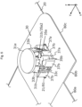
- the member to be engaged with the first engagement portion 31c of the first fastening portion 31 may be provided in the claw washer 33 (see the second embodiment, Fig. 14 ).
- a third engagement portion 33a2 corresponding to the second engagement portion 35a2 of the first embodiment is provided in the first flat portion hole 33a1 of the first flat portion 33a of the claw washer 33.
- the first flat portion hole 33a1 of the first flat portion 33a of the claw washer 33 is penetrated by the first shaft portion 31b of the first fastening portion 31 and is engaged with the first engagement portion 31c of the first shaft portion 31b, at the time of assembling the attachment portion 30.
- the first flat portion hole 33a1 has a shape in which the third engagement portion 33a2 is provided in the round hole.
- the third engagement portion 33a2 includes a convex portion protruding radially inward of the first shaft portion 31b so as to correspond to the recess of the first engagement portion 31c from the peripheral edge of said round hole.
- two third engagement portions 33a2 are provided so as to face each other in the y direction in accordance with the first engagement portion 31c.
- the holder 37 can be integrally constituted including a portion corresponding to the connection portion 35.
- the first fastening portion 31 rotates along with the rotation of the second fastening portion 39 when the device for vehicle 1 is attached to the bracket 80, by engagement between the first engagement portion 31c of the first fastening portion 31 and the third engagement portion 33a2 of the claw washer 33, fitting between the first leg portion 33b of the claw washer 33 and the third leg portion 37b of the holder 37, fitting between the third flat portion 37a of the holder 37 and the first attachment hole 21, and fitting between the third flat portion 37a of the holder 37 and the second attachment hole 81.
- the first fastening portion 31 and the claw washer 33 may be fixed by welding, or the like.
- first fastening portion 31 is a bolt and the second fastening portion 39 is a nut
- first fastening portion 31 may be a nut
- second fastening portion 39 may be a bolt (see the third embodiment, Fig. 15 ).
- the first fastening portion 31 of the third embodiment is provided with a second bearing portion 31d corresponding to the first bearing portion 39c of the second fastening portion 39 of the first embodiment.
- the second bearing portion 31d is provided with a second screw hole 31d1 corresponding to the first screw hole 39c1 of the first bearing portion 39c of the first embodiment.
- the second fastening portion 39 of the third embodiment is provided with the grip portion 39a corresponding to the head portion 31a of the first fastening portion 31 of the first embodiment, the flange portion 39b, and a second shaft portion 39d corresponding to the first shaft portion 31b of the first fastening portion 31 of the first embodiment.
- the second bearing portion 31d of the third embodiment is fixed to the first flat portion 33a of the claw washer 33 by welding, or the like. In Fig. 15 , a welded portion 31e between the second bearing portion 31d and the first flat portion 33a is indicated in black.
- the first fastening portion 31 rotates along with rotation of the second fastening portion 39 when the device for vehicle 1 is attached to the bracket 80, by fixing of the first fastening portion 31 and the claw washer 33 by welding, or the like, fitting between the first leg portion 33b of the claw washer 33 and the third leg portion 37b of the holder 37, fitting between the third flat portion 37a of the holder 37 and the first attachment hole 21, and fitting between the third flat portion 37a of the holder 37 and the second attachment hole 81.
- the device for vehicle 1 is an antenna device for vehicle
- the electronic equipment 10 is an antenna unit
- the device for vehicle 1 is not limited to these configurations.
- the electronic equipment 10 is a signal processing unit that processes data.
- the holding plate 20 and the holder 37 are separately constituted has been described.
- the holder 37 may be integrally formed with the holding plate 20.
- the holding plate 20 is constituted with a surface substantially perpendicular to the z direction, and the holding plate 20 is attached to the bracket 80 from below in the z direction.
- the holding plate 20 may be constituted with a surface perpendicular to the x direction or the y direction, and the holding plate 20 may be attached to the bracket 80 from the horizontal direction.
- An attachment portion includes a first fastening portion, a second fastening portion to be screwed with the first fastening portion, a detent portion provided between the first fastening portion and the second fastening portion, and a deformable member provided between the first fastening portion and the detent portion.
- the detent portion suppresses that at least one of the first fastening portion and the deformable member rotate(s) when the second fastening portion rotates.
- the second fastening portion is screwed with the first fastening portion whose rotation is suppressed by the detent portion, or the like.
- the deformable member is deformed, and sandwiches the attachment object with the second fastening portion.
- the attachment portion is fixed to the attachment object.
- inserting the first fastening portion or the like, and rotating (fastening) the second fastening portion can be performed from one side of the attachment object. Even in a state where a side of the attachment object on which the first fastening portion is located is not visible, it becomes possible to fix the attachment portion to the attachment object only by rotating the second fastening portion.
- the attachment portion or the like can be easily attached to the attachment object.
- the deformable member is a claw washer.
- a claw portion of the claw washer comes into contact with the attachment object by movement of the first fastening portion along with rotation of the second fastening portion. This enables attachment to the attachment object more reliably than attachment using a washer without a claw.
- the detent portion includes a holder that holds the claw washer.
- the holder is has a region in contact with an inner wall of an attachment hole which is provided in the attachment object and into which the attachment portion is to be inserted.
- the attachment hole and the region in contact with the attachment hole of the holder have a cross-sectional shape other than a perfect circle.
- the second fastening portion includes a flange portion.
- the flange portion has a larger cross-section than a cross-section of the attachment hole.
- the flange portion and the deformable member sandwich the attachment object.
- the first fastening portion is a bolt.
- the second fastening portion is a nut.
- a shaft portion of the bolt is provided with an engagement portion that engages with at least one of the detent portion and the deformable member.
- the first fastening portion is fixed to the claw washer.
- a device for vehicle includes electronic equipment, an electronic equipment holding portion that holds the electronic equipment, and an attachment portion for attaching the electronic equipment holding portion to a bracket of a vehicle.
- the electronic equipment holding portion includes a first attachment hole into which the attachment portion is to be inserted.
- the bracket includes a second attachment hole into which the attachment portion is to be inserted at a position overlapping with the first attachment hole.
- the attachment portion includes a first fastening portion, a second fastening portion to be screwed with the first fastening portion, a detent portion, and a deformable member.
- the detent portion is provided between the first fastening portion and the second fastening portion and suppresses that at least one of the first fastening portion and the deformable member rotate(s) when the second fastening portion rotates.
- the deformable member is provided between the first fastening portion and the detent portion. After the first fastening portion and the deformable member are inserted into the first attachment hole and the second attachment hole, the deformable member sandwiches the electronic equipment holding portion and the bracket with the second fastening portion by rotating the second fastening portion so as to be screwed with the first fastening portion
- the second fastening portion is screwed with the first fastening portion whose rotation is suppressed by the detent portion, or the like.
- the deformable member is deformed, and sandwiches the attachment object with the second fastening portion.
- the attachment portion is fixed to the attachment object.
- inserting the first fastening portion or the like and rotating (fastening) the second fastening portion can be performed from one side of the attachment object. Even in a state where the side of the attachment object on which the first fastening portion is located is not visible, it becomes possible to fix the attachment portion to the attachment object and to fix the electronic equipment holding portion provided between the attachment portion and the attachment object to the attachment object only by rotating the second fastening portion.
- the attachment portion or the like can be easily attached to the attachment object.
- the electronic equipment is electrically connected to the bracket via the electronic equipment holding portion and the attachment portion by the screwing.
- An attachment method is a method of attaching an attachment portion to an attachment object, the attachment portion including a first fastening portion, a second fastening portion to be screwed with the first fastening portion, a detent portion provided between the first fastening portion and the second fastening portion, and a deformable member provided between the first fastening portion and the detent portion.
- the attachment method includes: an insertion step of inserting the first fastening portion and the deformable member into an attachment hole of the attachment object; and a rotation step of rotating the second fastening portion so as to be screwed with the first fastening portion.
- the detent portion suppresses rotation of at least one of the first fastening portion and the deformable member, and the deformable member sandwiches the attachment object with the second fastening portion.
- An attachment method is a method of attaching an electronic equipment holding portion that holds electronic equipment to a bracket of a vehicle by an attachment portion including a first fastening portion, a second fastening portion to be screwed with the first fastening portion, a detent portion provided between the first fastening portion and the second fastening portion, and a deformable member provided between the first fastening portion and the detent portion.
- a device for vehicle includes the electronic equipment, the electronic equipment holding portion that holds the electronic equipment, and the attachment portion for attaching the electronic equipment holding portion to the bracket of the vehicle.
- the attachment method includes: an insertion step of inserting the first fastening portion and the deformable member into a first attachment hole provided in the electronic equipment holding portion and a second attachment hole provided in the bracket of the vehicle; and a rotation step of rotating the second fastening portion so as to be screwed with the first fastening portion.
- the detent portion suppresses rotation of at least one of the first fastening portion and the deformable member, and the deformable member sandwiches the electronic equipment holding portion and the bracket with the second fastening portion.
- An attachment method is a method of attaching an attachment portion to an attachment object, the attachment portion including a first fastening portion, a second fastening portion to be screwed with the first fastening portion, and a deformable member provided between the first fastening portion and the second fastening portion.
- the attachment method includes: an insertion step of inserting the first fastening portion and the deformable member into an attachment hole of the attachment object from one side of the attachment object and positioning the first fastening portion and the deformable member on the other side of the attachment object; and a rotation step of rotating the second fastening portion from one side so as to be screwed with the first fastening portion in a state where the first fastening portion does not rotate. By the rotation step, the deformable member sandwiches the attachment object from the other side with the second fastening portion on the one side.
Landscapes
- Engineering & Computer Science (AREA)
- General Engineering & Computer Science (AREA)
- Mechanical Engineering (AREA)
- Remote Sensing (AREA)
- Connection Of Plates (AREA)
- Fittings On The Vehicle Exterior For Carrying Loads, And Devices For Holding Or Mounting Articles (AREA)
- Bolts, Nuts, And Washers (AREA)
- Support Of Aerials (AREA)
Applications Claiming Priority (2)
| Application Number | Priority Date | Filing Date | Title |
|---|---|---|---|
| JP2020055354A JP6941705B1 (ja) | 2020-03-26 | 2020-03-26 | 取付部、車載装置、取り付け方法 |
| PCT/JP2021/005831 WO2021192740A1 (ja) | 2020-03-26 | 2021-02-17 | 取付部、車載装置、取り付け方法 |
Publications (2)
| Publication Number | Publication Date |
|---|---|
| EP4129767A1 true EP4129767A1 (de) | 2023-02-08 |
| EP4129767A4 EP4129767A4 (de) | 2024-04-24 |
Family
ID=77847140
Family Applications (1)
| Application Number | Title | Priority Date | Filing Date |
|---|---|---|---|
| EP21774619.7A Withdrawn EP4129767A4 (de) | 2020-03-26 | 2021-02-17 | Montageteil, bordvorrichtung und montageverfahren |
Country Status (5)
| Country | Link |
|---|---|
| US (1) | US12264701B2 (de) |
| EP (1) | EP4129767A4 (de) |
| JP (1) | JP6941705B1 (de) |
| CN (1) | CN115298446A (de) |
| WO (1) | WO2021192740A1 (de) |
Families Citing this family (2)
| Publication number | Priority date | Publication date | Assignee | Title |
|---|---|---|---|---|
| DE112023000037T5 (de) * | 2022-12-01 | 2024-07-18 | Woobo Tech Co., Ltd. | Teileinheit und struktur für den zusammenbau einer fahrzeugkarosserie |
| KR102581764B1 (ko) * | 2022-12-01 | 2023-09-25 | 주식회사 우보테크 | 부품 유닛 및 차체 조립 구조 |
Family Cites Families (28)
| Publication number | Priority date | Publication date | Assignee | Title |
|---|---|---|---|---|
| US3180387A (en) * | 1962-10-22 | 1965-04-27 | Dzus Fastener Co | Floating fastener receptacle |
| US3579942A (en) * | 1969-12-05 | 1971-05-25 | Thomas & Betts Corp | Fastener anchored in honeycomb panel |
| JPS5768807A (en) | 1980-10-16 | 1982-04-27 | Matsushita Electric Ind Co Ltd | Quartz double refraction plate |
| JPS5768807U (de) * | 1980-10-16 | 1982-04-24 | ||
| JPS58200812A (ja) * | 1982-05-14 | 1983-11-22 | 日産自動車株式会社 | 防水クリツプ |
| DE3620002A1 (de) * | 1986-06-13 | 1987-12-17 | Audi Ag | Fuer sonderzwecke einsetzbares kraftfahrzeug, beispielsweise polizeifahrzeug |
| US5146668A (en) * | 1991-06-18 | 1992-09-15 | Bulent Gulistan | Method for manufacturing part for floating nut assembly |
| JP3079307B2 (ja) * | 1996-07-10 | 2000-08-21 | 東京製綱株式会社 | 防音壁の外装板落下防止装置 |
| US6174118B1 (en) * | 1999-08-19 | 2001-01-16 | 3M Innovative Properties | Movable retention device for a threaded fastener |
| JP2001323607A (ja) * | 2000-05-12 | 2001-11-22 | Sanko Techno Co Ltd | ルーフボルト |
| US6879301B2 (en) * | 2001-10-09 | 2005-04-12 | Tyco Electronics Corporation | Apparatus and articles of manufacture for an automotive antenna mounting gasket |
| JP2006057776A (ja) * | 2004-08-23 | 2006-03-02 | Okitoku Gushiken | パネル材の係止締結装置 |
| JP2007158953A (ja) * | 2005-12-07 | 2007-06-21 | Alps Electric Co Ltd | 車載用アンテナ装置 |
| JP2007177986A (ja) | 2005-12-28 | 2007-07-12 | Aichi Mach Ind Co Ltd | 変速機 |
| DE102006034463B3 (de) * | 2006-07-26 | 2008-01-10 | A. Raymond Et Cie | Vorrichtung zum Befestigen eines Anbauteiles und eines Trägerteiles in einem Abstand voneinander |
| US8348332B2 (en) * | 2009-12-11 | 2013-01-08 | Honda Motor Co., Ltd. | Partition structure and installation structure for installation part |
| JP5112465B2 (ja) * | 2010-03-18 | 2013-01-09 | 原田工業株式会社 | ルーフマウントアンテナ取付構造 |
| CN101886653B (zh) * | 2010-07-12 | 2012-07-25 | 朱建华 | 一种紧固装置 |
| JP5110130B2 (ja) * | 2010-07-27 | 2012-12-26 | 株式会社デンソー | 車載電子制御ユニット用筺体 |
| JP2012047264A (ja) * | 2010-08-26 | 2012-03-08 | Panasonic Electric Works Co Ltd | ワーク取付構造 |
| JP6053728B2 (ja) * | 2014-08-14 | 2016-12-27 | 原田工業株式会社 | ルーフマウントアンテナ取付構造 |
| JP6588326B2 (ja) * | 2015-12-17 | 2019-10-09 | 株式会社やまびこ | 携帯型動力作業機における締付用ナットの落ち止め構造及びその締付用ナットの組付方法 |
| JP2018017254A (ja) * | 2016-07-25 | 2018-02-01 | トヨタ紡織株式会社 | 樹脂部品締結用の締結具 |
| WO2018096918A1 (ja) * | 2016-11-24 | 2018-05-31 | 株式会社ヨコオ | アンテナ取付部品及びアンテナ装置 |
| JP2018131075A (ja) * | 2017-02-16 | 2018-08-23 | アルプス電気株式会社 | 車両用ルーフアンテナ取付装置 |
| JP6818620B2 (ja) * | 2017-04-11 | 2021-01-20 | 株式会社ヨコオ | アンテナ取付装置、アンテナ装置の取付方法 |
| CN207338610U (zh) * | 2017-09-08 | 2018-05-08 | 凯士林汽车部件(苏州)有限公司 | 汽车车顶天线用快速安装结构 |
| PL3575617T3 (pl) * | 2018-05-31 | 2021-10-25 | Locinox | Zestaw mocujący |
-
2020
- 2020-03-26 JP JP2020055354A patent/JP6941705B1/ja active Active
-
2021
- 2021-02-17 EP EP21774619.7A patent/EP4129767A4/de not_active Withdrawn
- 2021-02-17 WO PCT/JP2021/005831 patent/WO2021192740A1/ja not_active Ceased
- 2021-02-17 CN CN202180021559.0A patent/CN115298446A/zh active Pending
- 2021-02-17 US US17/911,420 patent/US12264701B2/en active Active
Also Published As
| Publication number | Publication date |
|---|---|
| EP4129767A4 (de) | 2024-04-24 |
| WO2021192740A1 (ja) | 2021-09-30 |
| JP2021156329A (ja) | 2021-10-07 |
| JP6941705B1 (ja) | 2021-09-29 |
| US12264701B2 (en) | 2025-04-01 |
| CN115298446A (zh) | 2022-11-04 |
| US20230106963A1 (en) | 2023-04-06 |
Similar Documents
| Publication | Publication Date | Title |
|---|---|---|
| EP4129767A1 (de) | Montageteil, bordvorrichtung und montageverfahren | |
| US8059044B2 (en) | Antenna mounting apparatus and methods including claw fasteners and/or bayonet locking structures | |
| EP2927057B1 (de) | Befestigungsstruktur und -verfahren für ein fahrzeugaussenelement | |
| CN102317116B (zh) | 零件安装结构 | |
| JP5151939B2 (ja) | 電気接続箱 | |
| US7654864B2 (en) | Mounting bracket structure | |
| EP3599386B1 (de) | Bolzenverriegelungswerkzeug | |
| US9575514B2 (en) | Enclosure features of a portable computing device | |
| US20130056599A1 (en) | Apparatus and method for toollessly, releasably attaching components to a structure | |
| JP2017206197A (ja) | ワイヤハーネス及びそれを備えたインストルメントパネルモジュールの車体への組付方法 | |
| CN104134957B (zh) | 线束的车身临时固定结构 | |
| EP4198324B1 (de) | Verschiebbarer halteclip | |
| US20070099452A1 (en) | Apparatus of attaching part | |
| JP2010111136A (ja) | 内装部材の取付構造 | |
| WO2022189635A1 (en) | Snap-in fastener, metal housing and electronic device | |
| US20080030414A1 (en) | Antenna mounting assembly | |
| EP4685358A1 (de) | Montagestruktur und antennenvorrichtung | |
| US12267969B2 (en) | Display apparatus | |
| KR102919583B1 (ko) | 자동차용 번호판 보조대 | |
| US12614900B2 (en) | Power distribution box having a bracket | |
| JP4393246B2 (ja) | 液晶表示機器及びその製造方法 | |
| JP2015016785A (ja) | スピーカ取付構造 | |
| EP4668508A1 (de) | Montageeinheit und knoteneinheit | |
| US20170117624A1 (en) | Intermediate ground for vehicles | |
| US20210159683A1 (en) | Electrical element pass through plate constructions |
Legal Events
| Date | Code | Title | Description |
|---|---|---|---|
| STAA | Information on the status of an ep patent application or granted ep patent |
Free format text: STATUS: THE INTERNATIONAL PUBLICATION HAS BEEN MADE |
|
| PUAI | Public reference made under article 153(3) epc to a published international application that has entered the european phase |
Free format text: ORIGINAL CODE: 0009012 |
|
| STAA | Information on the status of an ep patent application or granted ep patent |
Free format text: STATUS: REQUEST FOR EXAMINATION WAS MADE |
|
| 17P | Request for examination filed |
Effective date: 20220804 |
|
| AK | Designated contracting states |
Kind code of ref document: A1 Designated state(s): AL AT BE BG CH CY CZ DE DK EE ES FI FR GB GR HR HU IE IS IT LI LT LU LV MC MK MT NL NO PL PT RO RS SE SI SK SM TR |
|
| DAV | Request for validation of the european patent (deleted) | ||
| DAX | Request for extension of the european patent (deleted) | ||
| A4 | Supplementary search report drawn up and despatched |
Effective date: 20240326 |
|
| RIC1 | Information provided on ipc code assigned before grant |
Ipc: H01Q 1/22 20060101ALI20240320BHEP Ipc: F16B 5/02 20060101ALI20240320BHEP Ipc: F16B 43/00 20060101ALI20240320BHEP Ipc: F16B 35/04 20060101ALI20240320BHEP Ipc: B60R 11/02 20060101AFI20240320BHEP |
|
| STAA | Information on the status of an ep patent application or granted ep patent |
Free format text: STATUS: THE APPLICATION HAS BEEN WITHDRAWN |
|
| 18W | Application withdrawn |
Effective date: 20240621 |