EP4123244A2 - Eisbereiter - Google Patents
Eisbereiter Download PDFInfo
- Publication number
- EP4123244A2 EP4123244A2 EP22184218.0A EP22184218A EP4123244A2 EP 4123244 A2 EP4123244 A2 EP 4123244A2 EP 22184218 A EP22184218 A EP 22184218A EP 4123244 A2 EP4123244 A2 EP 4123244A2
- Authority
- EP
- European Patent Office
- Prior art keywords
- water
- sump
- ice
- water level
- controller
- Prior art date
- Legal status (The legal status is an assumption and is not a legal conclusion. Google has not performed a legal analysis and makes no representation as to the accuracy of the status listed.)
- Granted
Links
Images



Classifications
-
- F—MECHANICAL ENGINEERING; LIGHTING; HEATING; WEAPONS; BLASTING
- F25—REFRIGERATION OR COOLING; COMBINED HEATING AND REFRIGERATION SYSTEMS; HEAT PUMP SYSTEMS; MANUFACTURE OR STORAGE OF ICE; LIQUEFACTION SOLIDIFICATION OF GASES
- F25C—PRODUCING, WORKING OR HANDLING ICE
- F25C1/00—Producing ice
- F25C1/22—Construction of moulds; Filling devices for moulds
- F25C1/25—Filling devices for moulds
-
- F—MECHANICAL ENGINEERING; LIGHTING; HEATING; WEAPONS; BLASTING
- F25—REFRIGERATION OR COOLING; COMBINED HEATING AND REFRIGERATION SYSTEMS; HEAT PUMP SYSTEMS; MANUFACTURE OR STORAGE OF ICE; LIQUEFACTION SOLIDIFICATION OF GASES
- F25C—PRODUCING, WORKING OR HANDLING ICE
- F25C1/00—Producing ice
- F25C1/12—Producing ice by freezing water on cooled surfaces, e.g. to form slabs
-
- F—MECHANICAL ENGINEERING; LIGHTING; HEATING; WEAPONS; BLASTING
- F25—REFRIGERATION OR COOLING; COMBINED HEATING AND REFRIGERATION SYSTEMS; HEAT PUMP SYSTEMS; MANUFACTURE OR STORAGE OF ICE; LIQUEFACTION SOLIDIFICATION OF GASES
- F25C—PRODUCING, WORKING OR HANDLING ICE
- F25C2400/00—Auxiliary features or devices for producing, working or handling ice
- F25C2400/14—Water supply
-
- F—MECHANICAL ENGINEERING; LIGHTING; HEATING; WEAPONS; BLASTING
- F25—REFRIGERATION OR COOLING; COMBINED HEATING AND REFRIGERATION SYSTEMS; HEAT PUMP SYSTEMS; MANUFACTURE OR STORAGE OF ICE; LIQUEFACTION SOLIDIFICATION OF GASES
- F25C—PRODUCING, WORKING OR HANDLING ICE
- F25C2500/00—Problems to be solved
- F25C2500/06—Spillage or flooding of water
-
- F—MECHANICAL ENGINEERING; LIGHTING; HEATING; WEAPONS; BLASTING
- F25—REFRIGERATION OR COOLING; COMBINED HEATING AND REFRIGERATION SYSTEMS; HEAT PUMP SYSTEMS; MANUFACTURE OR STORAGE OF ICE; LIQUEFACTION SOLIDIFICATION OF GASES
- F25C—PRODUCING, WORKING OR HANDLING ICE
- F25C2600/00—Control issues
- F25C2600/04—Control means
-
- F—MECHANICAL ENGINEERING; LIGHTING; HEATING; WEAPONS; BLASTING
- F25—REFRIGERATION OR COOLING; COMBINED HEATING AND REFRIGERATION SYSTEMS; HEAT PUMP SYSTEMS; MANUFACTURE OR STORAGE OF ICE; LIQUEFACTION SOLIDIFICATION OF GASES
- F25C—PRODUCING, WORKING OR HANDLING ICE
- F25C2700/00—Sensing or detecting of parameters; Sensors therefor
- F25C2700/04—Level of water
-
- F—MECHANICAL ENGINEERING; LIGHTING; HEATING; WEAPONS; BLASTING
- F25—REFRIGERATION OR COOLING; COMBINED HEATING AND REFRIGERATION SYSTEMS; HEAT PUMP SYSTEMS; MANUFACTURE OR STORAGE OF ICE; LIQUEFACTION SOLIDIFICATION OF GASES
- F25C—PRODUCING, WORKING OR HANDLING ICE
- F25C2700/00—Sensing or detecting of parameters; Sensors therefor
- F25C2700/14—Temperature of water
Definitions
- the present disclosure generally relates to an ice maker of the type that distributes water from a sump onto an ice formation device to form ice.
- Ice makers are in wide commercial and residential use. Certain ice makers (e.g., batch-type ice makers) operate by imparting water into a sump and the circulating water from the sump onto an ice formation device until a quantity of the water forms into ice on the ice formation device. For example, flow-down batch ice makers direct water from a sump to flow down along the front side of a generally vertical freeze plate. Some of the water freezes into ice, and the water that does not freeze falls into the sump so it can be recirculated to the freeze plate.
- Vertical spray batch ice makers operate by spraying sump water upward into downwardly opening ice molds in a horizontal freeze plate. Some of the water freezes into ice in the molds, and the unfrozen water is directed back to the sump where it can be recirculated.
- an ice maker comprises an ice formation device in which to form ice.
- a water system comprises a sump for holding water.
- a water pump is configured to circulate water from the sump to the ice formation device.
- a water inlet valve is configured to connect to a water supply. The water inlet valve is configured to selectively open and close to selectively impart water from the water supply into the sump.
- a refrigeration system is configured to cool the ice formation device for forming at least some of the water circulated by the water system into ice.
- a control system is configured to control the refrigeration system and the water system to conduct ice batch production cycles in which batches of ice are formed in the ice formation device.
- the control system includes a controller and a water level sensor configured to output a signal representative of water level in the sump to the controller.
- the controller is configured to execute a fill routine during each ice batch production cycle, during each fill routine.
- the controller is configured to fill the sump to a fill-approach level by opening the water inlet valve until the water level sensor outputs a signal indicating the water level in the sump has reached the fill-approach level. After receiving the signal indicating the water level in the sump as reached the fill-approach level, the water inlet valve is closed. After closing the water inlet valve, the sump is filled further to a freeze routine starting level by pulsing water through the water inlet valve until the water level sensor outputs a signal indicating the water level in the sump has reached the freeze routine starting level.
- an ice maker comprises an ice formation device in which to form ice.
- a water system comprises a sump for holding water and a pump configured to circulate water from the sump to the ice formation device.
- a refrigeration system is configured to cool the ice formation device for forming at least some of the water circulated by the water system into ice.
- a control system is configured to control the refrigeration system and the water system to conduct ice batch production cycles in which batches of ice are formed in the ice formation device.
- control system is configured to execute a differential freeze routine in which the control system circulates water from the sump to the ice formation device until water level decreases by a predefined differential amount from a high control water level based on the water level in the sump at a point in time after the sump was filled to a freeze routine starting level.
- an ice maker comprises an ice formation device in which to form ice.
- a water system comprises a sump for holding water and a pump configured to circulate water from the sump to the ice formation device.
- a refrigeration system is configured to cool the ice formation device for forming at least some of the water circulated by the water system into ice.
- a control system is configured to control the refrigeration system and the water system to conduct ice batch production cycles in which batches of ice are formed in the ice formation device.
- the control system includes a controller, a water level sensor configured to output a signal to the controller representative of water level in the sump, and a temperature sensor configured to output a signal to the controller representative of temperature of the water in the sump.
- the controller is configured to execute a differential freeze routine during each ice batch production cycle.
- the controller is configured to run the water pump to circulate water from the sump to the ice formation device. While running the water pump, the controller determines based on the signal output by the temperature sensor when the temperature of the water in the sump decreases to a pre-chill threshold, set a high control water level to a water level based on the signal output from the water level sensor when the water level in the sump decreases to the pre-chill temperature threshold, and determines based on the signal output from the water level sensor when the water level in the sump decreases from the high control water level by a predefined differential amount.
- the controller turns off the water pump in response to determining the water level in the sump has decreased from the high control water level by the predefined differential amount.
- an ice maker comprises an ice formation device in which to form ice.
- a water system comprises a sump for holding water and a pump configured to circulate water from the sump to the ice formation device.
- a refrigeration system is configured to cool the ice formation device for forming at least some of the water circulated by the water system into ice.
- a control system is configured to control the refrigeration system and the water system to conduct ice batch production cycles in which batches of ice are formed in the ice formation device.
- the control system is configured to execute a pulsed fill routine during each ice batch production cycle in which the control system pulses water from a water supply into the sump until the sump reaches a predefined freeze routine starting level.
- an exemplary embodiment of an ice maker is generally indicated at reference number 103.
- Ice makers in the scope of this disclosure may broadly comprise an ice formation device on which water can form into pieces of ice, a water system for circulating water to the ice formation device, and a refrigeration system configured to directly cool the ice formation device to a temperature at which at least some of the liquid water present on the ice formation device will freeze into ice.
- the ice maker is a batch ice maker of the type which has a generally vertical freeze plate 110 that constitutes the ice formation device.
- Other types of batch ice makers such as vertical spray ice makers are also contemplated to be in the scope of this disclosure.
- the ice formation device is typically a horizontal freeze plate including ice piece molds that open downward for receiving vertically sprayed water that forms into ice in the molds.
- the refrigeration system of the ice maker 103 includes a compressor 112, a heat rejecting heat exchanger 114, a refrigerant expansion device 118 for lowering the temperature and pressure of the refrigerant, an evaporator 120 along the back side of the freeze plate 110, and a hot gas valve 124.
- the compressor 112 can be a fixed speed compressor or a variable speed compressor to provide a broader range of operational control possibilities.
- the heat rejecting heat exchanger 114 may comprise a condenser for condensing compressed refrigerant vapor discharged from the compressor 112.
- the heat rejecting heat exchanger is able to reject heat from the refrigerant without condensing the refrigerant.
- Hot gas valve 124 is selectively opened to direct warm refrigerant from the compressor 114 directly to the evaporator 120 to remove or harvest ice cubes from the freeze plate 110 when the ice has reached the desired thickness.
- the refrigerant expansion device 118 can be of any suitable type, including a capillary tube, a thermostatic expansion valve, or an electronic expansion valve.
- the ice maker 110 may also include a temperature sensor 126 placed at the outlet of the evaporator 120 to control the refrigerant expansion device 118.
- the refrigerant expansion device 118 is an electronic expansion valve
- the ice maker 110 may also include a pressure transducer (not shown) placed at the outlet of the evaporator 120 to control the refrigerant expansion device 118 as is known in the art.
- a condenser fan 115 is positioned to blow the gaseous cooling medium across the condenser 114.
- the condenser fan 115 is a variable speed fan having a plurality of speed settings, including at least a normal speed and a high speed.
- the compressor 112 cycles a form of refrigerant through the condenser 114, expansion device 118, evaporator 120, and the hot gas valve 124, via refrigerant lines.
- a water system of the illustrated ice maker 10 includes a sump 130, a water pump 132, a water line 134 (broadly, passaging), and a water level sensor 136.
- the water pump 132 could be a fixed speed pump or a variable speed pump to provide a broader range of control possibilities.
- the water system of the ice maker 103 further includes a water supply line 138 and a water inlet valve 140 for filling the sump 130 with water from a water source (e.g., a municipal water utility).
- the illustrated water system further includes a drain line 142 (also called, drain passaging or a discharge line) and a drain valve 144 (e.g., purge valve, drain valve; broadly, a purge device) disposed thereon for draining water from the sump 130.
- the sump 130 is positioned below the freeze plate 110 to catch water coming off of the freeze plate such that the relatively cool water falling from the freeze plate may be recirculated by the water pump 132.
- the water line 134 fluidly connects the water pump 132 to a water distributor 146 above the freeze plate.
- the pump 132 is configured to pump water through the water line 134 and through the distributor 146.
- the distributor is configured to distribute the water imparted through the distributor 146 evenly across the front of the freeze plate 110 so that the water flows downward along the freeze plate and any unfrozen water falls off of the bottom of the freeze plate into the sump 130.
- the water level sensor 136 comprises a remote air pressure transducer 148.
- the water level sensor comprises a transducer that outputs a signal that continuously varies with water level as opposed to a conventional float switch that only changes its output at one or a small number of pre-selected water levels.
- the illustrated water level sensor could be replaced with an acoustic sensor, an electrical continuity sensor, a float sensor with a mechanical transducer providing a continuously variable output, etc.
- one or more float switches could be employed to implement certain aspects of level-based control described herein (e.g., the below-discussed pulsed fill routine could be executed using a float switch configuration instead of a level transducer).
- the illustrated water level sensor 136 includes a fitting 150 that is configured to couple the sensor to the sump 130.
- the fitting 150 is fluidly connected to a pneumatic tube 152.
- the pneumatic tube 152 provides fluid communication between the fitting 150 and the air pressure transducer 148.
- Water in the sump 130 traps air in the fitting 150 and compresses the air by an amount that varies with the level of the water in the sump.
- the water level in the sump 130 can be determined using the pressure detected by the air pressure transducer 148. Additional details of exemplary embodiments of a water level sensor comprising a remote air pressure transducer are described in U.S. Patent Application Publication No. 2016/0054043 , which is hereby incorporated by reference in its entirety.
- the ice maker 103 includes a controller 160 (e.g., a "local controller” or an “appliance controller”).
- the controller 160 includes at least one processor 162 for controlling the operation of the ice maker 103, e.g., for controlling at least one of the refrigeration system and the water system.
- the processor 162 of the controller 160 may include a non-transitory processor-readable medium storing code representing instructions to cause the processor to perform a process.
- the processor 162 may be, for example, a commercially available microprocessor, an application-specific integrated circuit (ASIC) or a combination of ASICs, which are designed to achieve one or more specific functions, or enable one or more specific devices or applications.
- ASIC application-specific integrated circuit
- the controller 160 may be an analog or digital circuit, or a combination of multiple circuits.
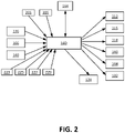
- the controller 160 may also include one or more memory components 164 ( FIG. 2 ) for storing data in a form retrievable by the controller.
- the controller 160 can store data in or retrieve data from the one or more memory components.
- the controller 160 may also comprise input/output (I/O) components to communicate with and/or control the various components of ice maker 103.
- the controller 160 may receive inputs such as, for example, one or more indications, signals, messages, commands, data, and/or any other information, from the water level sensor 136, a harvest sensor 166 for determining when ice has been harvested, an electrical power source (not shown), an ice level sensor 140 for detecting the level of ice in a bin (not shown) below the ice maker 103, and/or a variety of sensors and/or switches including, but not limited to, pressure transducers, temperature sensors, acoustic sensors, etc.
- the illustrated control system includes an integrated low side pressure transducer 203 and high side pressure transducer 205 that are configured to output (analog) signals to the controller 160 representative of refrigerant pressures upstream and downstream of the compressor 112 (e.g., the line pressure of the suction line and discharge line, respectively).
- control system comprises an evaporator temperature sensor 223 configured to output a signal representative of the temperature of the evaporator 120, an air temperature sensor 225 configured to output a signal representative of the temperature of air inside the ice maker 103, a water inlet temperature sensor 227 configured to output a signal representative of the temperature of water imparted into the ice maker, and a sump temperature sensor 229 configured to output a signal representative of a temperature of water in the sump 130.
- the controller 160 controls the ice maker 103 by outputting control signals to controllable output components such as the compressor 112, the condenser fan 115, the refrigerant expansion device 118, the hot gas valve 124, the water inlet valve 140, the drain valve 144, and/or the water pump 132.
- control signals may include one or more indications, signals, messages, commands, data, and/or any other information to such components.
- the hermetically sealed refrigeration system is charged with natural gas refrigerant.
- the refrigerant is r290.
- the natural gas refrigerant has a total charge of less than 150 g.
- Other types of refrigerants and levels of refrigerant charge could also be used without departing from the scope of the disclosure.
- the illustrated ice maker 103 is configured to conduct consecutive ice batch production cycles.
- Each ice batch production cycle comprises discrete routines for freezing the ice (a freeze routine), harvesting the ice (an ice harvesting routine), and filling the sump 130 (a fill routine).
- At least some of the ice batch production cycles can further comprise routines for purging hard water from the sump 130 after a batch of ice is formed and before the sump is refilled (a purge routine).
- the refrigeration system is operated to cool the freeze plate 110.
- the pump 132 circulates water from the sump 130 through the water line 134 and further through the distributor 146.
- the distributor 146 distributes water along the top portion of the freeze plate 110. As the water flows down the front of the freeze plate 110, some of the water freezes into ice, forming ice pieces on the freeze plate of gradually increasing thickness. The unfrozen water falls off of the freeze plate 110 back into the sump 130.
- the controller 160 switches from the freeze routine to the ice harvesting routine.
- Various methods are used in conventional ice makers to determine when ice achieves the desired volume (e.g., when ice on the freeze plate accumulates to the desired thickness).
- the freeze routine is terminated and harvest is initiated in response to a signal from the water level sensor indicating the gross water level in the sump has decreased to a predefined level believed to be correlated to the desired volume of ice.
- the present disclosure contemplates a new approach to determining when the desired amount of ice has been formed by the freeze routine.
- the new freezer routine (called a differential freeze routine herein) measures a high control water level at a point in time that provides substantially consistent conditions from batch to batch. Subsequently, the control system transitions from the freeze routine to the harvest routine when the water level decreases by a predefined differential amount associated with the preferred (target) ice volume.
- the controller Upon switchover from freeze routine to harvest routine, the controller turns off the pump 132 and opens the hot gas valve 124 to redirect hot refrigerant gas to the evaporator 120.
- the hot gas warms the freeze plate 110, causing the ice to melt.
- the melting ice falls from the freeze plate into an ice bin (not shown) below.
- the controller 160 closes the hot gas valve 124 after the ice has fallen from the freeze plate, as indicated by the harvest sensor 166.
- the controller 160 conducts a fill routine in which the controller opens the water inlet valve 140 to let new supply water into the sump 130.
- the water inlet valve 140 remains open until the control system registers an indication that the water level in the sump 130 reaches a desired ice making water level, at which point the water inlet valve is closed.
- the present disclosure contemplates a more advanced freeze routine that mitigates against overshoot and undershoot that occurs using the conventional process.
- the sump water functions as a cold reservoir and chills the new supply water that fills the sump from the end-of-circulation water level to the ice making water level. At least periodically, it is beneficial to purge a portion of the water from the sump 130.
- the controller 160 will periodically conduct a purge step by opening the drain valve 144 to purge a portion of the residual water from the sump 130.
- the controller 160 directs the drain valve 144 to close when the water level sensor 136 provides an indication to the controller that the water level in the sump 130 reaches the desired purge level.
- the drain valve 144 is one suitable type of purge mechanism but other types of purge mechanisms (e.g., active drain pumps) can also be used to execute the above-described purge step without departing from the scope of the disclosure.
- the inventor has recognized that the ice batch production cycle described above can be improved by ensuring that the same amount of water forms into ice during each cycle. Even small differences in the amount of water frozen in different ice batch production cycles can lead to consequential errors such as failure of ice to fully harvest during the harvest routine.
- a conventional approach to ensuring the same amount of water forms into ice during each cycle is to rely on predefined gross water levels in the sump. For example, during the fill routine, a conventional control system will use a water level sensor or float switch to fill the sump to a predefined fill level. That is, the conventional control system will close a water inlet valve after the water level sensor or float switch produces a signal indicating the predefined freeze routine starting level has been reached.
- the inventor has also recognized that another problem that leads to inconsistent ice batch volume is splashing.
- a conventional ice maker when the water pump turns on after a fill routine is complete, some water can initially splash out of the sump as water begins to fall into the sump off of the freeze plate. But the amount of water that splashes varies from batch to batch. In a conventional ice maker, the amount of water that splashes from the sump affects the final ice batch volume. If a large amount of volume splashes out of the sump, the ice batch will have less volume because less water must freeze on the freeze plate to reach a low water level that ends the freeze routine and initiates harvest. By contrast, if no water splashes out of the sump, more water must freeze before the low water level in the sump is reached.
- the inventor has conceived of two methods of controlling the ice maker 103 that improve the consistency in the amount of water used in each ice batch production cycle.
- the illustrated fill routine 310 may be referred to as a "pulsed fill routine" during which the controller 160 controls the water inlet valve 140 to pulse water from a water supply into the sump 130 until the sump reaches a predefined freeze routine starting water level.
- the controller 160 at the onset of the fill routine (e.g., upon completion of a harvest routine or a purge routine of an ice batch production cycle), the controller 160 initially starts a fill timer (step 312) and opens the water inlet valve 140 (step 314).
- the fill timer in step 312 is used to ensure that the fill routine 310 does not take an excessive amount of time, which would indicate a malfunction such as blockage of the water supply or a leaking sump.
- the illustrated fill routine 310 includes a decision point 333 at which the controller determines whether the fill timer has exceeded a predefined maximum fill time and a step 335 at which the controller outputs an alarm indication indicating that a fill error has occurred when the fill timer has exceeded the predefined maximum fill time. It can be seen that the controller 160 continuously monitors the fill timer for exceeding the predefined maximum fill time until the fill routine 310 ends.
- the initial valve opening performed in step 314 is not a pulsing of the water inlet valve 140. Rather, in step 314 the controller 160 opens the water inlet valve 140 and keeps the water inlet valve open until, based on decision point 316, the water level sensor 136 outputs a signal indicating the water level in the sump 130 has reached a predefined fill-approach level that is less than a freeze routine starting level at which the ice maker 103 ends the fill routine 310 and begins an freeze routine 410 ( FIG. 4 ). In one or more embodiments, the fill-approach level is in a range of from about 85% to about 95% of the freeze routine starting level.
- the controller 160 After receiving the signal indicating the water level in the sump as reached the fill-approach level, the controller 160 is configured to pulse the water from the water supply into the sump 130 until the water level sensor 136 outputs a signal indicating the water level in the sump 130 has reached the freeze routine starting level.
- the controller 160 determines that the water level in the sump 130 reaches the fill-approach water level, the controller initially closes the valve 140 (step 318) and keeps the valve closed for a measurement delay interval (step 320).
- the measurement delay interval may be in an inclusive range of from 1 seconds to 10 seconds.
- the controller 160 determines based on the signal output by the water level sensor 136 whether the water level in the sump 130 has reached the final ice making water level. If not, at step 324, the controller 160 opens the water inlet valve for a pulse interval to impart pulse water into the sump 130. In one or more embodiments, the pulse interval is in an inclusive range of from 1 seconds to 10 seconds.
- the controller 160 will close the water inlet valve 140 (step 318) when the pulse interval elapses and maintain the water inlet valve closed for another measurement delay interval (step 320). Provided that the fill timer has not exceed the maximum fill time (decision point 333), the controller 160 repeats the process of opening the water inlet valve 140 for a pulse interval (328) and then closing the water inlet valve for a delay interval until, at decision point 324, the controller determines based on the signal output by the water level sensor 136 that the water level in the sump reaches the freeze routine starting level. When at decision point 324, the controller determines that the water level in the sump 130 reaches the freeze routine starting level, the controller ends the fill routine 310 and begins a freeze routine.
- the pulsed fill routine 310 can be used to improve the consistency in the amount of ice produced in every ice batch production cycle. Pulsing the water from the fill-approach water level to the freeze routine starting level essentially eliminates the possibility of material overshoot or undershoot and thus provides a very consistent freeze routine starting level from which to execute an freeze routine. Thus, in one or more embodiments, the pulsed fill routine 310 is used to fill the sump before conducting a gross level-based freeze routine in which the controller circulates water from the sump onto the freeze plate until the controller determines based on a water level sensor that the gross water level in the sump has reached a predefined ice making completion level. In comparison with conventional ice makers that use conventional routines for transitioning from fill routine to freeze routine, the pulsed freeze routine 300 is believed to allow for greater consistency in ice volume when controlling the freeze routine based on gross levels in the sump.
- the pulsed fill routine 310 also may be used before a differential freeze routine in the scope of a further aspect of the present disclosure, which is generally indicated at reference number 410 in FIG. 4 .
- the differential freeze routine during 410 circulates water from the sump 130 to the freeze plate 110 (broadly, ice formation device) until water level in the sump decreases by a predefined differential amount from a high control water level achieved at a point in time after the sump as filled to the freeze routine starting level.
- the differential freeze routine 410 may also be used with ice makers that control the fill routine in other ways.
- the controller 160 initially conducts the pulsed fill routine 310 or another fill routine to fill the sump 130 to a freeze routine starting level. Then, at step 414, the controller 160 is configured to run the water pump 132 to circulate water from the sump 130 to the freeze plate 110 while operating the refrigeration system to chill the water being circulated. The circulating water thus begins to chill.
- the controller 160 monitors the output of the temperature sensor 129 to determine at decision point 416 when the temperature of the water in the sump 130 decreases to a pre-chill threshold.
- the pre-chill threshold indicates the water in the sump 130 is transitioning from sensible cooling to latent cooling -- that is, transitioning from a condition in which the cooling provided by the refrigeration system lowers the temperature of the water to a condition in which the cooling provided by the refrigeration system causes a phase change from liquid to solid without substantial temperature change.
- the predefined pre-chill threshold is in an inclusive range of from about 33°F to about 38°F.
- the controller 160 determines the water level in the sump 130 based on the signal output by the water level sensor 136 and, at step 418, sets that water level as a high control water level for purposes of differential control of the freeze routine 410. While continuing to run the water pump 132 to circulate water from the sump to the freeze plate 110, the controller 160 monitors the signal output from the water level sensor 136 to determine (based on the signal) when the water level in the sump 130 decreases from the high control water level (set in step 418) by a predefined differential amount corresponding to the desired amount of water to be formed into ice in each ice batch production cycle (see decision point 420).
- the controller 160 In response to the controller 160 determining that the water level in the sump 130 has decreased from the high control water level by the predefined differential amount in decision point 420, at step 422, the controller 160 turns off the water pump 132, ends the freeze routine 410, and begins an ice harvest routine (not shown).
- differential control By using differential control instead of absolute level control, the control system accounts for all variance that may occur due to overshooting or undershooting in a fill routine. Moreover, the inventor believes that the above-described differential control routine substantially mitigates against the adverse effects of splashing on the consistency of ice batch volume. By setting the high control water level at a time when the sump water is transitioning from sensible cooling to latent cooling, the control system ensures the subsequent differential measurement used to determine when the desired amount of ice has been formed is substantially unaffected by unpredictable events such as splash-out. Accordingly, the differential freeze routine 410 can provide improved consistency in ice batch volume.
- embodiments of the embodiments disclosed herein may be embodied as a system, method, computer program product or any combination thereof. Accordingly, embodiments of the disclosure may take the form of an entire hardware embodiment, an entire software embodiment (including firmware, resident software, micro-code, etc.) or an embodiment combining software and hardware aspects that may all generally be referred to herein as a "circuit,” “module” or “system.” Furthermore, aspects of the disclosure may take the form of a computer program product embodied in any tangible medium having computer usable program code embodied in the medium.
- aspects of the disclosure may be described in the general context of computer-executable or processor-executable instructions, such as program modules, being executed by a computer or processor.
- program modules include routines, programs, objects, components, data structures, etc. that perform particular tasks or implement particular abstract data types.
- aspects of the disclosure may also be practiced in distributed computing environments where tasks are performed by remote processing devices that are linked through a communications network.
- program modules may be located in both local and remote computer storage media including memory storage devices.
- the computer-usable or computer-readable medium may be, for example but not limited to, an electronic, magnetic, optical, electromagnetic, infrared, or semiconductor system, apparatus, device, or propagation medium.
- the computer-readable medium would include the following: an electrical connection having one or more wires, a portable computer diskette, a hard disk, a random access memory (RAM), a read-only memory (ROM), an erasable programmable read-only memory (EPROM or flash memory), an optical fiber, a portable compact disc read-only memory (CDROM), an optical storage device, a transmission media such as those supporting the Internet or an intranet, or a magnetic storage device.
- the computer-usable or computer-readable medium could even be paper or another suitable medium upon which the program is printed, as the program can be electronically captured, via, for instance, optical scanning of the paper or other medium, then compiled, interpreted, or otherwise processed in a suitable manner, if necessary, and then stored in a computer memory.
- a computer-usable or computer-readable medium may be any medium that can contain or store the program for use by or in connection with the instruction execution system, apparatus, or device.
- Computer program code for carrying out operations of the present disclosure may be written in any combination of one or more programming languages, including, but not limited to, an object oriented programming language such as Java, Smalltalk, C++, C# or the like and conventional procedural programming languages, such as the "C" programming language or similar programming languages.
- the program code may execute entirely on the portable electronic device, partly on the portable electronic device or refrigeration appliance, as a stand-alone software package, partly on the portable electronic device and partly on a remote computer, or entirely on a remote computer or server.
- the remote computer may be connected to the portable electronic device through any type of network, including a local area network (LAN) or a wide area network (WAN), or the connection may be made to an external computer (for example, through the Internet using an Internet Service Provider).
- LAN local area network
- WAN wide area network
- Internet Service Provider for example, AT&T, MCI, Sprint, EarthLink, MSN, GTE, etc.
Landscapes
- Engineering & Computer Science (AREA)
- Physics & Mathematics (AREA)
- Mechanical Engineering (AREA)
- Thermal Sciences (AREA)
- General Engineering & Computer Science (AREA)
- Production, Working, Storing, Or Distribution Of Ice (AREA)
Priority Applications (1)
| Application Number | Priority Date | Filing Date | Title |
|---|---|---|---|
| EP25193599.5A EP4617590A3 (de) | 2021-07-19 | 2022-07-11 | Eisbereiter |
Applications Claiming Priority (1)
| Application Number | Priority Date | Filing Date | Title |
|---|---|---|---|
| US17/378,997 US11686519B2 (en) | 2021-07-19 | 2021-07-19 | Ice maker with pulsed fill routine |
Related Child Applications (2)
| Application Number | Title | Priority Date | Filing Date |
|---|---|---|---|
| EP25193599.5A Division EP4617590A3 (de) | 2021-07-19 | 2022-07-11 | Eisbereiter |
| EP25193599.5A Division-Into EP4617590A3 (de) | 2021-07-19 | 2022-07-11 | Eisbereiter |
Publications (4)
| Publication Number | Publication Date |
|---|---|
| EP4123244A2 true EP4123244A2 (de) | 2023-01-25 |
| EP4123244A3 EP4123244A3 (de) | 2023-03-29 |
| EP4123244C0 EP4123244C0 (de) | 2026-03-18 |
| EP4123244B1 EP4123244B1 (de) | 2026-03-18 |
Family
ID=82446558
Family Applications (2)
| Application Number | Title | Priority Date | Filing Date |
|---|---|---|---|
| EP25193599.5A Pending EP4617590A3 (de) | 2021-07-19 | 2022-07-11 | Eisbereiter |
| EP22184218.0A Active EP4123244B1 (de) | 2021-07-19 | 2022-07-11 | Eisbereiter |
Family Applications Before (1)
| Application Number | Title | Priority Date | Filing Date |
|---|---|---|---|
| EP25193599.5A Pending EP4617590A3 (de) | 2021-07-19 | 2022-07-11 | Eisbereiter |
Country Status (3)
| Country | Link |
|---|---|
| US (2) | US11686519B2 (de) |
| EP (2) | EP4617590A3 (de) |
| CN (1) | CN115638578A (de) |
Citations (1)
| Publication number | Priority date | Publication date | Assignee | Title |
|---|---|---|---|---|
| US20160054043A1 (en) | 2014-08-22 | 2016-02-25 | True Manufacturing Co., Inc. | Draining the sump of an ice maker to prevent growth of harmful biological material |
Family Cites Families (165)
| Publication number | Priority date | Publication date | Assignee | Title |
|---|---|---|---|---|
| US2723536A (en) | 1953-03-18 | 1955-11-15 | Sabra E Mason | Apparatus for forming ice cubes |
| US3171266A (en) | 1961-07-06 | 1965-03-02 | Weisco Products Corp | Ice making machine with water distribution means |
| US3430452A (en) | 1966-12-05 | 1969-03-04 | Manitowoc Co | Ice cube making apparatus |
| GB1244831A (en) | 1967-09-29 | 1971-09-02 | Winget Ltd | Ice making apparatus |
| US3788095A (en) | 1971-05-25 | 1974-01-29 | Thiokol Chemical Corp | Spray-freezing apparatus and method |
| US3731496A (en) | 1972-01-31 | 1973-05-08 | Gen Electric | Photoelectric ice level sensor |
| US3812686A (en) | 1973-01-12 | 1974-05-28 | Winget Ltd | Ice making apparatus |
| US3913349A (en) | 1974-03-11 | 1975-10-21 | Ivan L Johnson | Ice maker with swing-out ice cube system |
| US4458503A (en) | 1980-05-16 | 1984-07-10 | King-Seeley Thermos Co. | Ice product and method and apparatus for making same |
| US4884413A (en) * | 1989-03-13 | 1989-12-05 | Specialty Equipment Companies, Inc. | Ice machine |
| US5182925A (en) | 1991-05-13 | 1993-02-02 | Mile High Equipment Company | Integrally formed, modular ice cuber having a stainless steel evaporator and microcontroller |
| US5477694A (en) | 1994-05-18 | 1995-12-26 | Scotsman Group, Inc. | Method for controlling an ice making machine and apparatus therefor |
| JPH08285419A (ja) | 1995-04-10 | 1996-11-01 | Matsushita Refrig Co Ltd | 製氷装置 |
| US5922030A (en) | 1995-12-20 | 1999-07-13 | Nartron Corporation | Method and system for controlling a solid product release mechanism |
| JP3307861B2 (ja) | 1997-10-21 | 2002-07-24 | ホシザキ電機株式会社 | 流下式製氷機 |
| JPH11142033A (ja) | 1997-11-07 | 1999-05-28 | Hoshizaki Electric Co Ltd | 流下式製氷機 |
| JP3342377B2 (ja) | 1997-11-20 | 2002-11-05 | ホシザキ電機株式会社 | 製氷装置 |
| US7284391B2 (en) | 1998-10-06 | 2007-10-23 | Manitowoc Foodservice Companies, Inc. | Pump assembly for an ice making machine |
| US6705107B2 (en) | 1998-10-06 | 2004-03-16 | Manitowoc Foodservice Companies, Inc. | Compact ice making machine with cool vapor defrost |
| US6196007B1 (en) | 1998-10-06 | 2001-03-06 | Manitowoc Foodservice Group, Inc. | Ice making machine with cool vapor defrost |
| JP4293652B2 (ja) | 1998-10-21 | 2009-07-08 | ホシザキ電機株式会社 | 氷ディスペンサー |
| US6209340B1 (en) | 1998-12-07 | 2001-04-03 | Imi Cornelius Inc. | Ice clearing structure for ice makers |
| US6484530B1 (en) | 1999-05-18 | 2002-11-26 | Hoshizaki Denki Kabushiki Kaisha | Flow-down type ice making machinery |
| JP4477723B2 (ja) | 1999-11-25 | 2010-06-09 | ホシザキ電機株式会社 | オーガの製造方法 |
| JP3667593B2 (ja) | 2000-04-21 | 2005-07-06 | ホシザキ電機株式会社 | オープンセルタイプ自動製氷機 |
| JP3868758B2 (ja) | 2000-05-02 | 2007-01-17 | ホシザキ電機株式会社 | 製氷機 |
| US6607096B2 (en) | 2000-08-15 | 2003-08-19 | Manitowoc Foodservice Companies, Inc. | Volumetric ice dispensing and measuring device |
| US6324855B1 (en) | 2000-08-29 | 2001-12-04 | Hoshizaki America, Inc. | Proximity ice level detector, proximity detector assembly and methods |
| US6637227B2 (en) | 2000-09-15 | 2003-10-28 | Mile High Equipment Co. | Quiet ice making apparatus |
| US6463746B1 (en) | 2000-09-27 | 2002-10-15 | Scotsman Ice Systems | Ice producing machine and method with gear motor monitoring |
| US6418736B1 (en) | 2001-06-20 | 2002-07-16 | Hoshizaki America, Inc. | Ice level detector |
| JP3702204B2 (ja) | 2001-08-13 | 2005-10-05 | ホシザキ電機株式会社 | 貯氷庫の氷放出機構部 |
| US6681580B2 (en) | 2001-09-12 | 2004-01-27 | Manitowoc Foodservice Companies, Inc. | Ice machine with assisted harvest |
| WO2003035536A2 (en) | 2001-10-19 | 2003-05-01 | Manitowoc Foodservice Companies, Inc. | Beverage dispenser with integral ice maker |
| US6880358B2 (en) | 2002-03-16 | 2005-04-19 | Manitowoc Foodservice Companies, Inc. | Ice and ice/beverage dispensers |
| US6907744B2 (en) | 2002-03-18 | 2005-06-21 | Manitowoc Foodservice Companies, Inc. | Ice-making machine with improved water curtain |
| US7017355B2 (en) | 2003-03-07 | 2006-03-28 | Scotsman Ice Systems | Ice machine evaporator assemblies with improved heat transfer and method for making same |
| US7062925B2 (en) | 2003-06-24 | 2006-06-20 | Hoshizaki Denki Kabushiki Kaisha | Method of operating auger icemaking machine |
| TWI335407B (en) | 2003-12-19 | 2011-01-01 | Hoshizaki Electric Co Ltd | Automatic ice making machine |
| WO2005074562A2 (en) | 2004-02-03 | 2005-08-18 | Scotsman Ice Systems | Maintenance and cleaning for an ice machine |
| US7287671B2 (en) | 2004-04-16 | 2007-10-30 | Manitowoc Foodservice Companies, Inc. | Beverage dispenser modular manifold |
| JP2006010181A (ja) | 2004-06-24 | 2006-01-12 | Hoshizaki Electric Co Ltd | 自動製氷機の除氷運転方法 |
| US8484935B2 (en) | 2004-07-06 | 2013-07-16 | Daniel D. LeBlanc | Ice bagging system and method |
| US7340913B2 (en) | 2004-08-05 | 2008-03-11 | Manitowoc Foodservice Companies, Inc. | Ice machine and ice-making assembly including a water distributor |
| JP2006064289A (ja) | 2004-08-26 | 2006-03-09 | Hoshizaki Electric Co Ltd | 冷却装置 |
| US7168262B2 (en) | 2005-03-24 | 2007-01-30 | Hoshizaki Denki Kabushiki Kaisha | Ice making machine |
| US7281386B2 (en) | 2005-06-14 | 2007-10-16 | Manitowoc Foodservice Companies, Inc. | Residential ice machine |
| EP1938030A2 (de) | 2005-09-02 | 2008-07-02 | Manitowoc Foodservice Companies, Inc. | Eis-/getränke-spender mit in-line eishacker |
| USD540830S1 (en) | 2005-09-29 | 2007-04-17 | Hoshizaki Denki Kabushiki Kaisha | Ice dispenser |
| USD537457S1 (en) | 2005-11-01 | 2007-02-27 | Manitowoc Foodservice Companies, Inc. | Ice machine door |
| USD526338S1 (en) | 2005-11-10 | 2006-08-08 | Manitowoc Foodservice Companies, Inc. | Ice machine |
| US7273990B2 (en) | 2005-11-10 | 2007-09-25 | Hoshizaki Denki Kabushiki Kaisha | Ice storage detection switch |
| US7444828B2 (en) | 2005-11-30 | 2008-11-04 | Hoshizaki Denki Kabushiki Kaisha | Ice discharging structure of ice making mechanism |
| ITMI20060250A1 (it) | 2006-02-10 | 2007-08-11 | Frimont Spa | Macchina per la fabbricazione di ghiaccio |
| USD557716S1 (en) | 2006-03-13 | 2007-12-18 | Hoshizaki Denki Kabushiki Kaisha | Ice machine |
| US8087533B2 (en) | 2006-05-24 | 2012-01-03 | Hoshizaki America, Inc. | Systems and methods for providing a removable sliding access door for an ice storage bin |
| JP5139290B2 (ja) | 2006-07-20 | 2013-02-06 | ホシザキ電機株式会社 | 飲料注出装置 |
| JPWO2008026292A1 (ja) | 2006-09-01 | 2010-01-14 | ホシザキ電機株式会社 | 流下式製氷機 |
| JPWO2008038341A1 (ja) | 2006-09-26 | 2010-01-28 | ホシザキ電機株式会社 | 冷却機構を備えた装置 |
| US9188378B2 (en) | 2006-10-31 | 2015-11-17 | Hoshizaki America, Inc. | Systems and methods for providing an ice storage bin control sensor and housing |
| CN101495825B (zh) | 2006-11-02 | 2011-01-26 | 星崎电机株式会社 | 自动制冰机及其运转方法 |
| US7832219B2 (en) | 2006-12-29 | 2010-11-16 | Manitowoc Foodservice Companies, Inc. | Ice making machine and method |
| KR100900287B1 (ko) | 2006-12-29 | 2009-05-29 | 엘지전자 주식회사 | 제빙장치 및 그 제어방법 |
| JP4934501B2 (ja) | 2007-05-22 | 2012-05-16 | ホシザキ電機株式会社 | 流下式製氷機の散水案内器 |
| JP5097459B2 (ja) | 2007-06-22 | 2012-12-12 | ホシザキ電機株式会社 | 製氷機の運転方法 |
| US7975497B2 (en) | 2007-06-27 | 2011-07-12 | Hoshizaki Denki Kabushiki Kaisha | Refrigeration unit having variable performance compressor operated based on high-pressure side pressure |
| US8136365B2 (en) | 2007-07-02 | 2012-03-20 | Hoshizaki Denki Kabushiki Kaisha | Cooling apparatus having a variable speed compressor with speed limited on the basis of a sensed performance parameter |
| US20090179040A1 (en) | 2008-01-16 | 2009-07-16 | Lancer Partnership, Ltd. | Method and apparatus for an ice level determiner |
| TWD130386S1 (zh) | 2008-03-27 | 2009-08-11 | 星崎電機股份有限公司 | 製冰機 |
| JP5165440B2 (ja) | 2008-03-31 | 2013-03-21 | ホシザキ電機株式会社 | 貯氷庫を装備する製氷機 |
| JP5405168B2 (ja) | 2008-04-01 | 2014-02-05 | ホシザキ電機株式会社 | 流下式製氷機の製氷ユニット |
| KR101535482B1 (ko) | 2008-04-15 | 2015-07-09 | 엘지전자 주식회사 | 냉장고 제빙기의 만빙 감지 장치 |
| CA2665782A1 (en) | 2008-05-15 | 2009-11-15 | Manitowoc Foodservice Companies, Inc. | Heat exchanger, particularly for use in a beverage dispenser |
| US8336741B2 (en) | 2008-06-24 | 2012-12-25 | Manitowoc Foodservice Companies, Llc | Front-accessible ice dispenser ice agitation motor |
| JP5380103B2 (ja) | 2009-02-16 | 2014-01-08 | ホシザキ電機株式会社 | 扉体の保持構造 |
| JP5198337B2 (ja) | 2009-03-25 | 2013-05-15 | ホシザキ電機株式会社 | 自動製氷機 |
| KR20100110183A (ko) | 2009-04-02 | 2010-10-12 | 엘지전자 주식회사 | 제빙장치 및 이를 구비한 냉장고 및 이 냉장고의 제빙방법 |
| JP5826264B2 (ja) | 2010-06-30 | 2015-12-02 | マニトワック・フードサービス・カンパニーズ・エルエルシー | フレーバード氷を連続的又は半連続的に生成する方法及びシステム |
| JP5657116B2 (ja) | 2010-08-02 | 2015-01-21 | マニトワック・フードサービス・カンパニーズ・エルエルシー | 水体が氷結している間に水体中を伝搬する音波の解析 |
| CN102346448B (zh) | 2010-08-03 | 2014-11-12 | 曼尼托沃食品服务有限公司 | 用于通知制冰周期启动时延的低压控制 |
| USD649565S1 (en) | 2010-08-04 | 2011-11-29 | Manitowoc Foodservice Companies, Llc | Ice machine |
| CN202064788U (zh) | 2010-08-04 | 2011-12-07 | 曼尼托沃食品服务有限公司 | 用于储冰盒的门组件 |
| JP5788008B2 (ja) | 2010-09-24 | 2015-09-30 | マニトワック・フードサービス・カンパニーズ・エルエルシー | リモート飲料システムに省エネルギーをもたらすシステムおよび方法 |
| PL2463603T3 (pl) | 2010-12-10 | 2014-09-30 | Scotsman Group Llc | Przegubowe kurtynowe ścianki do wytwornic lodu |
| EP2673579A1 (de) | 2011-02-09 | 2013-12-18 | Manitowoc Foodservice Companies, LLC | Verfahren und systeme zur verbesserung und aufrechterhaltung der sauberkeit von eismaschinen |
| USD668272S1 (en) | 2011-02-10 | 2012-10-02 | Manitowoc Foodservice Companies LLC | Ice machine |
| USD673185S1 (en) | 2011-02-10 | 2012-12-25 | Manitowoc Foodservice Companies, Llc | Ice machine |
| USD653682S1 (en) | 2011-02-10 | 2012-02-07 | Manitowoc Foodservice Companies, Llc | Ice machine |
| USD669920S1 (en) | 2011-02-10 | 2012-10-30 | Manitowoc Foodservice Companies, Llc | Ice machine |
| CN103857978B (zh) | 2011-08-12 | 2016-05-18 | 曼尼托沃食品服务有限公司 | 用于冰储存和分配设备的卫生系统和方法 |
| BR112014005408A2 (pt) | 2011-09-06 | 2017-03-28 | Manitowoc Foodservice Companies LLC | método e sistema para controlar gotejamento de um distribuidor de bebida por meio de uma válvula de expansão |
| US9052130B2 (en) | 2012-01-13 | 2015-06-09 | Manitowoc Foodservice Companies, Llc | Low refrigerant volume condenser for hydrocarbon refrigerant and ice making machine using same |
| US9625199B2 (en) | 2012-07-11 | 2017-04-18 | Mainitowoc Foodservice Companies, Llc | Methods and apparatus for adjusting ice slab bridge thickness and initiate ice harvest following the freeze cycle |
| USD692032S1 (en) | 2012-07-11 | 2013-10-22 | Manitowoc Foodservice Companies, Llc | Ice machine |
| US9351571B2 (en) | 2012-07-11 | 2016-05-31 | Manitowoc Foodservice Companies, Llc | Connection assembly for a base and a cabinet assembly of an ice maker |
| USD690743S1 (en) | 2012-07-11 | 2013-10-01 | Manitowoc Foodservice Companies, Llc | Ice machine interface |
| US10107538B2 (en) | 2012-09-10 | 2018-10-23 | Hoshizaki America, Inc. | Ice cube evaporator plate assembly |
| US20140137594A1 (en) | 2012-11-21 | 2014-05-22 | True Manufacturing Company, Inc. | Ice storage bin with improved door and improved door incorporating hooks |
| US20140144175A1 (en) | 2012-11-28 | 2014-05-29 | True Manufacturing Company, Inc. | Undercounter ice maker with increased capacity ice storage bin |
| RU2015129756A (ru) | 2012-12-21 | 2017-01-27 | Манитовок Фудсервис Компаниз, Ллк | Способ и система для крепления и снятия литого формованного системного клапана с устройства для распределения напитков |
| WO2014116799A1 (en) | 2013-01-25 | 2014-07-31 | True Manufacturing Company, Inc. | Ice maker with slide out sump |
| US9644879B2 (en) | 2013-01-29 | 2017-05-09 | True Manufacturing Company, Inc. | Apparatus and method for sensing ice thickness and detecting failure modes of an ice maker |
| US9863682B2 (en) | 2013-01-30 | 2018-01-09 | True Manufacturing Company, Inc. | Water distribution for an ice maker |
| JP6230623B2 (ja) | 2013-02-05 | 2017-11-15 | トゥルー・マニュファクチュアリング・カンパニー・インコーポレイテッドTrue Manufacturing Co., Inc. | ポータブル電子デバイスを備えた冷却装置のコントロール |
| US9643828B2 (en) | 2013-04-08 | 2017-05-09 | Manitowoc Foodservice Companies, Llc | Arcuate multi-dispensing beverage dispenser |
| USD734783S1 (en) | 2013-05-07 | 2015-07-21 | Manitowoc Foodservice Companies, Llc | Ice storage bin and door |
| WO2014189839A1 (en) | 2013-05-20 | 2014-11-27 | Manitowoc Foodservice Companies, Llc | Hybrid beverage dispenser |
| USD734371S1 (en) | 2013-10-09 | 2015-07-14 | Manitowoc Foodservice Companies, Llc | Ice machine having a grill |
| WO2015065564A1 (en) | 2013-10-31 | 2015-05-07 | Manitowoc Foodservice Companies, Llc | Ice making machine evaporator with joined partition intersections |
| US9243833B2 (en) | 2013-11-05 | 2016-01-26 | General Electric Company | Ice making system for a refrigerator appliance and a method for determining an ice level within an ice bucket |
| ES2821808T3 (es) | 2013-12-27 | 2021-04-27 | Hoshizaki Corp | Lavavajillas |
| KR102315152B1 (ko) | 2014-01-08 | 2021-10-19 | 트루 매뉴팩쳐링 코., 인크. | 각 얼음 제빙기용 가변 동작점 구성 요소 |
| US10059580B2 (en) | 2014-05-06 | 2018-08-28 | Manitowoc Foodservice Companies, Llc | Modular beverage cooling system |
| US20150377538A1 (en) | 2014-06-30 | 2015-12-31 | Manitowoc Foodservice Companies, Llc | Water distribution system for ice-making machine |
| US9523526B2 (en) | 2014-07-02 | 2016-12-20 | Follett Corporation | Ice making apparatus and process of reducing scale buildup and flushing the apparatus |
| MX2017000349A (es) | 2014-07-09 | 2017-08-25 | Manitowoc Foodservice Companies LLC | Montaje de cuchillas batidoras. |
| KR20170046643A (ko) | 2014-07-15 | 2017-05-02 | 매니토웍 푸드서비스 컴퍼니즈, 엘엘씨 | 블렌딩 컨테인먼트 어셈블리를 위한 시스템 및 방법 |
| EP3179892A1 (de) | 2014-08-14 | 2017-06-21 | Manitowoc Foodservice Companies, LLC | Spülanordnung für mixer |
| KR102279393B1 (ko) | 2014-08-22 | 2021-07-21 | 삼성전자주식회사 | 냉장고 |
| WO2016053670A1 (en) | 2014-10-01 | 2016-04-07 | True Manufacturing Co., Inc. | Edge-lit door for refrigerator unit |
| US10001306B2 (en) | 2014-10-09 | 2018-06-19 | Scottsman Group LLC | Ice-making freezer cleaning |
| US9939186B2 (en) | 2014-10-24 | 2018-04-10 | Scotsman Group Llc | Evaporator assembly for ice-making apparatus and method |
| US20180022594A1 (en) | 2014-10-31 | 2018-01-25 | First Element Packaging Inc. | Container for receiving and storing fluid |
| US20160159520A1 (en) | 2014-12-04 | 2016-06-09 | Manitowoc Foodservice Companies, Llc | Devices for improved evacuation of ingredient containers |
| WO2016089410A1 (en) | 2014-12-04 | 2016-06-09 | Manitowoc Foodservice Companies, Llc | Devices for improved evacuation of ingredient containers |
| CN105485993A (zh) | 2015-03-19 | 2016-04-13 | 斯科茨曼制冰系统(上海)有限公司 | 一种制冰机及使用这种制冰机的制冰方法 |
| JP6384374B2 (ja) | 2015-03-23 | 2018-09-05 | 株式会社デンソー | エジェクタ式冷凍サイクル |
| CN107466256A (zh) | 2015-04-06 | 2017-12-12 | 真实制造有限公司 | 具有自动除垢和消毒功能的制冰机 |
| EP3280959B1 (de) | 2015-04-09 | 2021-03-03 | True Manufacturing Co., Inc. | Verfahren und vorrichtungen zur steuerung des ertragszyklus einer eismaschine mit einem ertragssensor und einem temperatursensor |
| CN107532837A (zh) | 2015-05-06 | 2018-01-02 | 真实制造有限公司 | 具有用以维持清洁冷凝器的反向冷凝器风扇电动机的制冰机 |
| WO2016183206A1 (en) | 2015-05-11 | 2016-11-17 | True Manufacturing Co., Inc. | Ice maker with push notification to indicate when maintenance is required |
| WO2016181702A1 (ja) | 2015-05-14 | 2016-11-17 | ホシザキ株式会社 | 自動製氷機 |
| ES2769798T3 (es) | 2015-05-22 | 2020-06-29 | Lancer Corp | Métodos y aparato para desinfectar dispensadores |
| US10300161B2 (en) | 2015-06-19 | 2019-05-28 | Manitowoc Foodservice Companies, Llc | Method and apparatus for sanitation of ice production and dispensing system |
| WO2017004212A1 (en) | 2015-07-02 | 2017-01-05 | Manitowoc Foodservice Companies, Llc | Multi-evaporator sequencing apparatus and method |
| GB2544053B (en) | 2015-11-03 | 2021-07-21 | Welbilt Halesowen Ltd | A drinks dispensing system |
| WO2017083359A1 (en) | 2015-11-09 | 2017-05-18 | Manitowoc Foodservice Companies, Llc | Dispense valve mounting block and method of using same |
| US10012345B2 (en) | 2015-12-01 | 2018-07-03 | Lancer Corporation | Method and apparatus for an icemaker adapter |
| DE102015225581A1 (de) | 2015-12-17 | 2017-06-22 | Convotherm Elektrogeräte GmbH | Verfahren zum Betreiben eines gewerblichen Gargeräts |
| MX378951B (es) | 2015-12-21 | 2025-03-11 | True Mfg Co Inc | Máquina para fabricar hielo con evaporador de circuito doble para refrigerante de hidrocarburo. |
| DE102016204834B4 (de) | 2016-03-23 | 2024-05-29 | Welbilt Deutschland GmbH | Gewerbliches Gargerät |
| US20170299246A1 (en) | 2016-04-14 | 2017-10-19 | Lancer Corporation | Ice chest system |
| DE102016206483B4 (de) | 2016-04-18 | 2026-02-12 | Welbilt Deutschland GmbH | Verfahren zum Feststellen einer Reinigungsnotwendigkeit eines gewerblichen Gargeräts, und gewerbliches Gargerät |
| KR101707636B1 (ko) * | 2016-04-25 | 2017-02-17 | 주식회사 카이저제빙기 | 신속제빙용 수직형 제빙기 |
| US10401071B2 (en) | 2016-06-23 | 2019-09-03 | True Manufacturing Co., Inc. | Ice maker with capacitive water level sensing |
| DE102016212162A1 (de) | 2016-07-04 | 2018-01-04 | Convotherm-Elektrogeräte Gmbh | Gewerbliches Gargerät |
| IT201600072581A1 (it) | 2016-07-12 | 2018-01-12 | Scotsman Ice S R L | Macchina per la produzione di ghiaccio. |
| EP3485207B1 (de) | 2016-07-15 | 2022-09-07 | True Manufacturing Co., Inc. | Eisbereiter |
| US10107540B2 (en) | 2016-07-29 | 2018-10-23 | Manitowoc Foodservice Companies, Llc | Refrigerant system with liquid line to harvest line bypass |
| WO2018022097A1 (en) | 2016-07-29 | 2018-02-01 | Manitowoc Foodservice Companies, Llc | Refrigerant system with liquid line to harvest line bypass |
| US10156393B2 (en) | 2016-09-09 | 2018-12-18 | Haier Us Appliance Solutions, Inc. | Stand-alone ice making appliance |
| US10717631B2 (en) | 2016-11-22 | 2020-07-21 | Manitowoc Crane Companies, Llc | Optical detection and analysis of crane hoist and rope |
| MY193626A (en) | 2016-11-23 | 2022-10-20 | True Mfg Co Inc | Sanitary evaporator assembly |
| WO2018147843A1 (en) | 2017-02-08 | 2018-08-16 | Manitowoc Foodservice Companies, Llc | Reinforced hand scoop |
| US10539342B2 (en) | 2017-02-08 | 2020-01-21 | The Delfield Company, Llc | Small refrigerant receiver for use with thermostatic expansion valve refrigeration system |
| DE102017203511A1 (de) | 2017-03-03 | 2018-10-04 | Convotherm-Elektrogeräte Gmbh | Verfahren und Vorrichtung zur gezielten Informationsvermittlung an Gargeräte nutzende Kunden und/oder Gargeräte eines Gargeräte-Herstellers |
| US10731908B2 (en) | 2017-04-26 | 2020-08-04 | Electrolux Home Products, Inc. | Refrigeration appliance with cold air supply for ice maker and ice level sensor |
| DE102017209399A1 (de) | 2017-06-02 | 2018-12-06 | Convotherm-Elektrogeräte Gmbh | Gargerät |
| US10801770B2 (en) | 2018-01-16 | 2020-10-13 | Manitowoc Foodservice Companies, Llc | Dispensing ice bin with sliding sleeve metering device |
| WO2019143354A1 (en) | 2018-01-19 | 2019-07-25 | Manitowoc Foodservice Companies, Llc | Ice-making machine that utilizes closed-loop harvest control with vibrational feedback |
| US10480843B2 (en) | 2018-01-19 | 2019-11-19 | Manitowoc Foodservice Companies, Llc | Ice-making machine that utilizes closed-loop harvest control with vibrational feedback |
| IT201800002500A1 (it) | 2018-02-08 | 2019-08-08 | Scotsman Ice S R L | Fabbricatore di ghiaccio |
| WO2019164480A1 (en) | 2018-02-21 | 2019-08-29 | Manitowoc Foodservice Companies, Llc | Versatile mount external scoop holder |
| JP7321944B2 (ja) * | 2020-01-08 | 2023-08-07 | ホシザキ株式会社 | 製氷機 |
| US11802727B2 (en) | 2020-01-18 | 2023-10-31 | True Manufacturing Co., Inc. | Ice maker |
-
2021
- 2021-07-19 US US17/378,997 patent/US11686519B2/en active Active
-
2022
- 2022-07-11 EP EP25193599.5A patent/EP4617590A3/de active Pending
- 2022-07-11 EP EP22184218.0A patent/EP4123244B1/de active Active
- 2022-07-19 CN CN202210849542.0A patent/CN115638578A/zh active Pending
-
2023
- 2023-05-10 US US18/314,887 patent/US12305904B2/en active Active
Patent Citations (1)
| Publication number | Priority date | Publication date | Assignee | Title |
|---|---|---|---|---|
| US20160054043A1 (en) | 2014-08-22 | 2016-02-25 | True Manufacturing Co., Inc. | Draining the sump of an ice maker to prevent growth of harmful biological material |
Also Published As
| Publication number | Publication date |
|---|---|
| CN115638578A (zh) | 2023-01-24 |
| EP4617590A2 (de) | 2025-09-17 |
| US20230272959A1 (en) | 2023-08-31 |
| EP4123244C0 (de) | 2026-03-18 |
| US11686519B2 (en) | 2023-06-27 |
| US12305904B2 (en) | 2025-05-20 |
| EP4617590A3 (de) | 2025-11-19 |
| EP4123244B1 (de) | 2026-03-18 |
| US20230017067A1 (en) | 2023-01-19 |
| EP4123244A3 (de) | 2023-03-29 |
Similar Documents
| Publication | Publication Date | Title |
|---|---|---|
| US20250172327A1 (en) | Draining the sump of an ice maker to prevent growth of harmful biological material | |
| US11543161B2 (en) | Ice maker with reversing condenser fan motor to maintain clean condenser | |
| US12624876B2 (en) | Ice maker with pressure transducers | |
| US20120031126A1 (en) | Control system for an ice maker | |
| EP1912029B1 (de) | Kühleinheit | |
| US5829257A (en) | Methods and systems for harvesting ice in an ice making apparatus | |
| CN103913024B (zh) | 用于控制变速压缩机的速度的方法 | |
| JP2005201545A (ja) | 自動製氷機の多重製氷判定方法および運転方法 | |
| CN107940874A (zh) | 冰箱智能化霜控制方法、控制器及制冷设备和存储介质 | |
| US20070157636A1 (en) | Icemaker control system | |
| JP5052173B2 (ja) | 自動製氷機の運転方法 | |
| KR20220022257A (ko) | 제빙기의 탈빙 온도 제어 방법 | |
| US12305904B2 (en) | Ice maker with differential sump fill routine | |
| JP2009121768A (ja) | 自動製氷機およびその制御方法 | |
| US5894734A (en) | Water-circulating type ice maker | |
| JP2008138914A (ja) | 冷凍装置、及び冷凍機油の戻し方法 | |
| HK40087669A (zh) | 制冰机 | |
| JPH09145210A (ja) | 自動製氷機付き冷凍冷蔵庫 | |
| HK40081239A (en) | Ice maker | |
| JP6386778B2 (ja) | 冷凍装置 | |
| CN115406146B (zh) | 一种制冰控制方法、装置及制冰机 | |
| CN211782072U (zh) | 一种水冷箱式冷水机组 | |
| TR2024011545A2 (tr) | Bi̇r buz yapma özelli̇kli̇ soğutucu ci̇haz ve soğutucu ci̇hazlar i̇çi̇n bi̇r buz yapma yöntemi̇ | |
| JP2007051857A (ja) | 製氷機 | |
| JPS5938688Y2 (ja) | 自動製氷機 |
Legal Events
| Date | Code | Title | Description |
|---|---|---|---|
| PUAI | Public reference made under article 153(3) epc to a published international application that has entered the european phase |
Free format text: ORIGINAL CODE: 0009012 |
|
| STAA | Information on the status of an ep patent application or granted ep patent |
Free format text: STATUS: THE APPLICATION HAS BEEN PUBLISHED |
|
| AK | Designated contracting states |
Kind code of ref document: A2 Designated state(s): AL AT BE BG CH CY CZ DE DK EE ES FI FR GB GR HR HU IE IS IT LI LT LU LV MC MK MT NL NO PL PT RO RS SE SI SK SM TR |
|
| PUAL | Search report despatched |
Free format text: ORIGINAL CODE: 0009013 |
|
| AK | Designated contracting states |
Kind code of ref document: A3 Designated state(s): AL AT BE BG CH CY CZ DE DK EE ES FI FR GB GR HR HU IE IS IT LI LT LU LV MC MK MT NL NO PL PT RO RS SE SI SK SM TR |
|
| RIC1 | Information provided on ipc code assigned before grant |
Ipc: F25C 1/12 20060101AFI20230220BHEP |
|
| STAA | Information on the status of an ep patent application or granted ep patent |
Free format text: STATUS: REQUEST FOR EXAMINATION WAS MADE |
|
| 17P | Request for examination filed |
Effective date: 20230906 |
|
| RBV | Designated contracting states (corrected) |
Designated state(s): AL AT BE BG CH CY CZ DE DK EE ES FI FR GB GR HR HU IE IS IT LI LT LU LV MC MK MT NL NO PL PT RO RS SE SI SK SM TR |
|
| GRAP | Despatch of communication of intention to grant a patent |
Free format text: ORIGINAL CODE: EPIDOSNIGR1 |
|
| STAA | Information on the status of an ep patent application or granted ep patent |
Free format text: STATUS: GRANT OF PATENT IS INTENDED |
|
| RIC1 | Information provided on ipc code assigned before grant |
Ipc: F25C 1/25 20180101ALI20250214BHEP Ipc: F25C 1/12 20060101AFI20250214BHEP |
|
| INTG | Intention to grant announced |
Effective date: 20250307 |
|
| GRAJ | Information related to disapproval of communication of intention to grant by the applicant or resumption of examination proceedings by the epo deleted |
Free format text: ORIGINAL CODE: EPIDOSDIGR1 |
|
| STAA | Information on the status of an ep patent application or granted ep patent |
Free format text: STATUS: REQUEST FOR EXAMINATION WAS MADE |
|
| GRAP | Despatch of communication of intention to grant a patent |
Free format text: ORIGINAL CODE: EPIDOSNIGR1 |
|
| STAA | Information on the status of an ep patent application or granted ep patent |
Free format text: STATUS: GRANT OF PATENT IS INTENDED |
|
| INTC | Intention to grant announced (deleted) | ||
| INTG | Intention to grant announced |
Effective date: 20250728 |
|
| GRAJ | Information related to disapproval of communication of intention to grant by the applicant or resumption of examination proceedings by the epo deleted |
Free format text: ORIGINAL CODE: EPIDOSDIGR1 |
|
| STAA | Information on the status of an ep patent application or granted ep patent |
Free format text: STATUS: REQUEST FOR EXAMINATION WAS MADE |
|
| GRAP | Despatch of communication of intention to grant a patent |
Free format text: ORIGINAL CODE: EPIDOSNIGR1 |
|
| STAA | Information on the status of an ep patent application or granted ep patent |
Free format text: STATUS: GRANT OF PATENT IS INTENDED |
|
| INTC | Intention to grant announced (deleted) | ||
| INTG | Intention to grant announced |
Effective date: 20251008 |
|
| GRAS | Grant fee paid |
Free format text: ORIGINAL CODE: EPIDOSNIGR3 |
|
| GRAA | (expected) grant |
Free format text: ORIGINAL CODE: 0009210 |
|
| STAA | Information on the status of an ep patent application or granted ep patent |
Free format text: STATUS: THE PATENT HAS BEEN GRANTED |
|
| AK | Designated contracting states |
Kind code of ref document: B1 Designated state(s): AL AT BE BG CH CY CZ DE DK EE ES FI FR GB GR HR HU IE IS IT LI LT LU LV MC MK MT NL NO PL PT RO RS SE SI SK SM TR |
|
| REG | Reference to a national code |
Ref country code: CH Ref legal event code: F10 Free format text: ST27 STATUS EVENT CODE: U-0-0-F10-F00 (AS PROVIDED BY THE NATIONAL OFFICE) Effective date: 20260318 Ref country code: GB Ref legal event code: FG4D |
|
| REG | Reference to a national code |
Ref country code: IE Ref legal event code: FG4D |
|
| U01 | Request for unitary effect filed |
Effective date: 20260324 |
|
| U07 | Unitary effect registered |
Designated state(s): AT BE BG DE DK EE FI FR IT LT LU LV MT NL PT RO SE SI Effective date: 20260330 |