EP4120874B1 - Möbel und schubelement für ein möbel - Google Patents
Möbel und schubelement für ein möbel Download PDFInfo
- Publication number
- EP4120874B1 EP4120874B1 EP21713370.1A EP21713370A EP4120874B1 EP 4120874 B1 EP4120874 B1 EP 4120874B1 EP 21713370 A EP21713370 A EP 21713370A EP 4120874 B1 EP4120874 B1 EP 4120874B1
- Authority
- EP
- European Patent Office
- Prior art keywords
- wall
- drawer
- element according
- drawer element
- lighting device
- Prior art date
- Legal status (The legal status is an assumption and is not a legal conclusion. Google has not performed a legal analysis and makes no representation as to the accuracy of the status listed.)
- Active
Links
Images




Classifications
-
- A—HUMAN NECESSITIES
- A47—FURNITURE; DOMESTIC ARTICLES OR APPLIANCES; COFFEE MILLS; SPICE MILLS; SUCTION CLEANERS IN GENERAL
- A47B—TABLES; DESKS; OFFICE FURNITURE; CABINETS; DRAWERS; GENERAL DETAILS OF FURNITURE
- A47B88/00—Drawers for tables, cabinets or like furniture; Guides for drawers
- A47B88/90—Constructional details of drawers
- A47B88/941—Drawers being constructed from two or more parts
-
- A—HUMAN NECESSITIES
- A47—FURNITURE; DOMESTIC ARTICLES OR APPLIANCES; COFFEE MILLS; SPICE MILLS; SUCTION CLEANERS IN GENERAL
- A47B—TABLES; DESKS; OFFICE FURNITURE; CABINETS; DRAWERS; GENERAL DETAILS OF FURNITURE
- A47B97/00—Furniture or accessories for furniture, not provided for in other groups of this subclass
-
- A—HUMAN NECESSITIES
- A47—FURNITURE; DOMESTIC ARTICLES OR APPLIANCES; COFFEE MILLS; SPICE MILLS; SUCTION CLEANERS IN GENERAL
- A47B—TABLES; DESKS; OFFICE FURNITURE; CABINETS; DRAWERS; GENERAL DETAILS OF FURNITURE
- A47B2220/00—General furniture construction, e.g. fittings
- A47B2220/0075—Lighting
- A47B2220/0077—Lighting for furniture, e.g. cupboards and racks
-
- A—HUMAN NECESSITIES
- A47—FURNITURE; DOMESTIC ARTICLES OR APPLIANCES; COFFEE MILLS; SPICE MILLS; SUCTION CLEANERS IN GENERAL
- A47B—TABLES; DESKS; OFFICE FURNITURE; CABINETS; DRAWERS; GENERAL DETAILS OF FURNITURE
- A47B2220/00—General furniture construction, e.g. fittings
- A47B2220/0091—Electronic or electric devices
- A47B2220/0097—Remote control for furniture, e.g. tables or shelves
-
- F—MECHANICAL ENGINEERING; LIGHTING; HEATING; WEAPONS; BLASTING
- F21—LIGHTING
- F21V—FUNCTIONAL FEATURES OR DETAILS OF LIGHTING DEVICES OR SYSTEMS THEREOF; STRUCTURAL COMBINATIONS OF LIGHTING DEVICES WITH OTHER ARTICLES, NOT OTHERWISE PROVIDED FOR
- F21V33/00—Structural combinations of lighting devices with other articles, not otherwise provided for
- F21V33/0004—Personal or domestic articles
- F21V33/0012—Furniture
Definitions
- the invention relates to a push element for a piece of furniture, in particular a drawer, having at least one wall which is formed at least in sections by a translucent wall element, the wall element having two opposing narrow surfaces.
- the invention further relates to a piece of furniture with such a push element.
- Push elements of the type mentioned above are, for example, drawers, also called drawers, which usually have walls in addition to side walls, a rear wall and a front wall facing the user, often just called the front.
- drawers also called drawers
- at least one of the side, rear or front walls mentioned is partially translucent, for example in that it is formed in sections by a translucent wall element.
- lighting devices in particular LEDs (light-emitting diodes), in such a way that they shine into the wall element from a narrow surface. Due to internal reflection, the light spreads over the entire surface of the wall element and leaves the wall element partly via the side surfaces, i.e. the wall surfaces, and partly via the narrow surfaces, also called the end surfaces of the wall element. In this way, the interior of the thrust element can be attractively illuminated.
- Such an arrangement is, for example, from the publication DE 20 2009 000 472 U1 known.
- the document describes the irradiation of light preferably by a lighting device which is arranged along the upper narrow surface. Alternatively, irradiation is also described from the lower horizontal narrow surface or from the vertical narrow surfaces.
- the state of the art is also out WO 2010/023047 and DE 20 2015 100770 U1 known.
- the lighting device When irradiation occurs along the upper horizontal narrow surface into the wall element, this narrow surface is therefore covered by the lighting device and does not represent an optically effective light exit surface.
- the upper narrow surface When irradiating into a vertical narrow surface or into the lower horizontal narrow surface, the upper narrow surface can remain free, so that it also serves as a light exit surface.
- the light emerging there can vary depending on its intensity and also the Radiation characteristics can be perceived as disturbing.
- Other users on the other hand, see such radiation as a particularly interesting lighting effect.
- a push element according to the invention of the type mentioned at the beginning is characterized in that the translucent wall element can be removed from the wall and can be reused rotated by 180 ° about a horizontal axis, the two narrow surfaces of the wall element that are horizontal in the installed position having different optical properties.
- the visual appearance can be varied, especially in a lighting situation. Because the wall element is removable in the wall, the user can make a change themselves depending on their preference.
- the two narrow surfaces which are horizontal in the installed position, have a structure in the area of their surface that produces different light scattering.
- one of the horizontal narrow surfaces is produced using a treatment process and the other horizontal narrow surface is produced either using a different treatment process or the same treatment process as the first-mentioned narrow surface, but then with different characteristics.
- one of the horizontal narrow surfaces is polished, whereas the opposite horizontal narrow surface is roughened, in particular satin finished.
- the polished narrow surface allows maximum light emission upwards during operation.
- the roughened, particularly satinized surface advantageously does not completely prevent light from escaping, but leads to a gentler and glare-free light emission.
- the roughened narrow surface is coated so that it is protected from a film of grease, for example from fingerprints. Through coating, the roughened surface retains its optical scattering effect for the light.
- other surface treatments can be provided on at least one of the narrow surfaces, for example a geometric structuring, a covering by a more or less translucent covering material, for example a varnish and/or a coloring, for example by dyes that have penetrated into the material of the wall element.
- Suitable treatment processes include, for example, coating processes, organic or ceramic screen printing, foiling, milling, grinding, engraving, blasting processes such as sandblasting or glass bead blasting, etching processes, laser engraving, or hemming.
- the parallel, opposite side surfaces of the wall element are also designed to be optically different. Due to the different design, the external appearance of the drawer can be varied depending on the installation position of the wall element. Which of the two side surfaces is on the inside of the push element and which is on the outside can be selected by rotating the wall element through 180° around a vertical axis. In combination with rotation around the aforementioned horizontal axis, each wall element can be used in a total of four different installation positions in terms of their visual appearance.
- a different appearance of the two side surfaces is advantageously achieved by structuring. Different structuring leads to different light outputs.
- the wall element is constructed from two wall elements placed parallel to one another.
- a decorative film can also be arranged between the two surface elements, on which there is, for example, a pattern that becomes visible, in particular when illuminated by the lighting device.
- an engraving can also be made into the wall element, which is particularly visible in a lighting situation.
- the wall element can be provided in one side wall or in both side walls, or can be arranged additionally or exclusively in the front and/or the rear wall.
- a lighting device is assigned to the wall element, with the lighting device shining into at least one of the horizontal narrow surfaces or a vertical narrow surface. Radiation into one or both vertical narrow surfaces is advantageous in that the optical properties of the surface into which the radiation is irradiated do not change when the wall element is rotated by 180 ° about a horizontal axis, so that the same conditions exist in each of the two operating positions the irradiation of light is present.
- the lighting device preferably has at least one LED or one OLED (organic LED).
- the thrust element is assigned a control device for controlling the lighting device.
- the control device is preferably designed to control the lighting device according to the principle of human centric lighting. This lighting concept takes into account the visual, emotional and biological effects of light.
- the control device controls at least the color temperature and the lighting intensity over the course of the day.
- an arrangement can be formed from a lighting device, a control unit and a pusher element for a piece of furniture, the pusher element being characterized by the fact that it has at least one wall which is formed at least in sections by a translucent wall element, the wall element having opposing narrow surfaces, the Lighting device radiates at least into a narrow surface of the wall element and wherein the lighting device is designed according to the principle of human centric lighting.
- control unit has a wireless data interface, wherein the wireless data interface communicates with at least one Internet-capable control center and wherein the control center communicates with other devices of a different type, the devices of a different type being an action of the control unit Lighting device can trigger or the control unit of the lighting device triggers an action of the foreign devices.
- the wireless data interface can form a mesh network with further wireless data interfaces of other devices or lighting devices.
- the control center can be formed by or integrated into a smart home system. This configuration can be implemented both in the thrust element according to the invention and in the aforementioned arrangement of lighting device, control device and thrust element.
- the wall element can be secured in the wall by a lock. In this way, the push element can also be lifted on the wall elements during assembly without the wall elements slipping out.
- a piece of furniture according to the invention is characterized by the use of at least one such push element. This results in the advantages mentioned in connection with the thrust element.
- the push element can in particular be designed as a drawer, also called a drawer.
- top, bottom, left, right initially refer to the exemplary representation chosen in the respective figures.
- top and bottom in connection with a drawer, the representation in the figures corresponds to the orientation usually assumed in space, in which a bottom of the drawer is aligned horizontally and the drawer is open at the top.
- front and rear refer to an extension direction of an extension guide of the drawer.
- Fig. 1 shows a drawer 1 as an example of a push element according to the application for a piece of furniture.
- the drawer 1 according to Fig. 1 has a total of four walls 2, 3, 4, including two parallel side walls 2, a rear wall 3 and a front wall 4, also referred to as front 4.
- the walls 2-4 mentioned surround a floor 5.
- the side walls 2 are designed in several parts. They each include a longitudinal beam 21 arranged at the bottom of the side wall 2, onto which a flat wall element 22 is placed.
- the wall element 22 is framed by two covers 23, which cover connecting elements 24 on which the side wall 2 is connected to the rear wall 3 or the front 4.
- the rear wall 3 and the covers 23 are made from sheet metal material in a punching-bending process.
- the front 4 and the bottom 5 can be made, for example, from wood or a wood material or plastic, but also from metal, for example.
- not only the side walls 2, but also or exclusively the rear wall 3 and/or the front wall 4 can be designed in several parts with an insertable wall element 22.
- An exemplary embodiment in which all walls 2-4 are designed in this way is shown, for example, in FIGS Fig. 7a, b shown.
- the side wall 2 which is composed of several sections, is in the Fig. 2 shown separately from drawer 1 in more detail in an isometric drawing.
- the covers 23 are shown removed from the side wall in an exploded view to show the structure of the connecting element 24, which is otherwise covered by the cover 23.
- the connecting elements 24 are firmly connected to the longitudinal beam 21 and can also be formed in one piece with components of the longitudinal beam.
- the connecting elements 24 include components with which a possibly locking connection to the rear wall 3 or to the front 4 can be established. Adjusting elements can be present which, for example, enable a change in the height and/or side position of the front 4 relative to the side walls 2, for example in order to be able to adjust gap dimensions in the front area of a piece of furniture.
- the drawer 1 below the longitudinal beam 21, the drawer 1 can be coupled to a running rail of a pull-out guide in order to be able to extend the drawer 1 out of the furniture.
- the wall element 22 is framed by the longitudinal beam 21 and the connecting elements 24 in a U-shape along three narrow surfaces. Side surfaces 221 of the wall element 22 and an upper horizontal narrow surface 222 are exposed. To accommodate the wall element 22, U-shaped receiving rails 241 are arranged on the connecting elements 24, into which the wall element 22 can be inserted from above when a locking part 242 is pivoted to the side.
- the Fig. 3a and 3b show the area of the receiving rail 241 on the connecting element 24 and the locking part 242 in more detail.
- the locking part 242 is designed as a pivotally mounted lever.
- the locking part 242 can also be designed as a slide, for example.
- Fig. 3a the locking part 242 is swung out so that the wall element 22, which is in the Fig. 3a and 3b shown at a distance from the receptacle 241 can be inserted.
- the wall element 22 is gripped over in the corner area at the top and is thereby fixed between the two connecting elements 24.
- the locking part 242 is no longer accessible and is fixed in its closed position.
- the closed position of the locking part 242 is in the two detail sections Fig. 4 reproduced again from two different perspectives.
- the wall element 22 (unlike in the Fig. 3a , b ) shown in its correct position inserted into the receiving rail 241.
- the wall element 22 is translucent, for example transparent, but at least translucent.
- light-emitting diodes (LEDs) 243 are arranged as lighting devices, which can be supplied with operating current via a connecting cable with a plug 244.
- the LEDs 243 are thus positioned so that they radiate light into a vertical narrow surface 223 of the wall element 22.
- Such LEDs 243 can be arranged on one or both connecting elements 24, so that light is irradiated into the wall element 22 from one or two opposite sides.
- the lighting devices can be supplied with power, for example, via an energy storage device which is arranged on the drawer 1. This can be arranged, for example, on the outside of the rear wall 3, within the connecting elements 24, inside the drawer or below the base 5.
- a rechargeable or non-rechargeable battery or a high-capacity capacitor also known as a supercap or supercapacitor
- a power supply unit arranged externally to the drawer 1 may be present to recharge the energy storage.
- a connection from the power supply to the energy storage device is preferably established when the drawer 1 is retracted.
- the connection can be made, for example, via appropriate Contacts are made on the rear wall 3 of the drawer 1, which contact associated mating contacts in the furniture body in which the drawer 1 is arranged when the drawer 1 is retracted.
- the power supply can be provided specifically for this purpose.
- an existing power supply unit for example a drawer drive, which is arranged on the furniture, can also be used.
- a charging circuit for the energy storage device can be designed as a wide-range device that tolerates input voltages in a wide voltage range and as direct or alternating voltage and outputs a constant output voltage for the charging process.
- a control device which detects an opening of the drawer 1 and switches on the LEDs 243 when the drawer 1 is open.
- the open state can be detected, for example, via a magnetic sensor (reed contact or Hall sensor).
- the magnetic sensor can be arranged on the drawer 1 and interact with a magnet that is stationary on the furniture body. Switching via a mechanical scanning pushbutton switch, a motion sensor, an acceleration sensor or optically via a light barrier is also conceivable.
- this contact can also be evaluated and the information obtained can be used to switch on the LEDs 243. It can also be provided that the lighting is switched off after a predetermined or adjustable time if the drawer is not closed.
- a busbar can also be provided, through which the drawer 1 is permanently supplied with electricity.
- the pull-out guides can be used as busbars.
- the lighting device can have several LEDs 243, which either have the same optical properties (e.g. color, color temperature, intensity) or different ones. It can be provided that LEDs 243 with different properties can be selectively controlled by the control device. For example, if warm white and cold white LEDs 243 are used, whose brightness can be adjusted independently of one another, white light with different color temperatures can be mixed additively. Instead of or in addition to warm white and cold white LEDs, colored LEDs can also be provided in the lighting device, in particular red, green and blue LEDs, in order to cover a large color space through color mixing. The red, green and blue LEDs can be separate LEDs or can be used in the form of so-called RGB LEDs, which combine light chips of the three colors mentioned in one housing.
- RGB LEDs which combine light chips of the three colors mentioned in one housing.
- control elements can be present on the control device, or it can alternatively or additionally be provided with a wireless data interface.
- a wireless data interface can be done, for example, via WLAN, Bluetooth, ZigBee, ZWAVE and, for example, on the frequencies 433 MHz or 868 MHz or other suitable frequencies.
- KNX or IP can also be used as protocols.
- the device can communicate with external devices and, for example, be “Smart Home” capable and can also be controlled via voice control.
- different drawers can be networked with each other or be linked to a smart home central unit. This makes it possible, for example, for only the top open drawer to be illuminated if two drawers arranged one above the other are open. Alternatively, both drawers could be illuminated, provided that the front of the lower drawer is in front of that of the drawer above, with positions of the drawer being recorded using appropriate sensors.
- a warning function (e.g. of a risk of tipping over) can be implemented, which causes the lighting device of a drawer to flash or something similar if, for example, more than one drawer in a piece of furniture is pulled out.
- the lighting device or sensors coupled to the associated control device could also be part of a smart home alarm system and, for example, trigger a siren or send a message to a person.
- a signaling function can be implemented in a smart home system, which also causes the lighting device of a drawer to flash or something similar triggered, for example, when the doorbell is pressed or the telephone rings.
- the lighting effects can vary. For example, pressing the doorbell may cause the lighting device to flash, while ringing the telephone may cause the lighting device to flash.
- the lighting device can, for example, be designed according to the concepts of Human Centric Lighting (HCL).
- Human Centric Lighting includes a lighting concept that takes the visual, emotional and biological effects of light into account.
- the light from the lighting device is transmitted by reflection on the inner surfaces of the side surfaces 221 and leaves the wall surfaces partly through the side surfaces 221 and partly through the upper horizontal narrow surface 222, whereby a desired illumination effect is achieved.
- the wall element 22 can also be easily removed by the user due to the type of assembly of the wall element 22 by inserting it into the receiving rails 241. It is designed in such a way that it can be reinserted rotated by 180° about a horizontal axis, so that the other horizontal narrow surface 224 opposite the previously upper horizontal narrow surface 222 (cf. Fig. 5a ) then lies on top and is visible. According to the application, the two horizontal narrow surfaces 222, 224 are designed optically differently, so that a different effect or impression is achieved in the lighting. It can be provided that an adapter is used, for example to accommodate a narrower wall element 22. The adapter can also have transparent features or recesses to achieve an effect or impression.
- FIG. 5a This one is in Fig. 5a for a first embodiment of a wall element 22 shown.
- a top view of the side surface 221 of the wall element 22 is shown in the middle of the figure.
- On the left and right are top views of the two horizontal narrow surfaces 222, 224 in the installed position, namely on the left of the first horizontal narrow surface already visible in the previously described figures 222 and on the right to a second horizontal narrow surface 224 opposite the first.
- the first horizontal narrow surface 222 is a polished surface and the second horizontal narrow surface 224 is a roughened, in particular satin surface.
- the wall element 22 can be made of glass or a translucent plastic, for example Plexiglas, for example a plastic containing polycarbonate.
- the different degrees of roughness of the narrow surfaces 222, 224 lead to light emission of different intensity and with a different radiation profile.
- narrow surfaces 222, 224 In addition to polishing or satin finishing, other surface treatments can also be carried out on one or both narrow surfaces 222, 224, which make the narrow surfaces 222, 224 visually different. Examples are a geometric structuring, a covering by a more or less translucent covering material, for example a varnish and/or a coloring, for example by dyes diffused into the material of the wall element. Alternatively, laser engraving can also be carried out in the edge area of the narrow surface coating 222, 224 in order to create different illumination effects.
- Fig. 5b is in the same way as in Fig. 5a a second embodiment of a wall element 22 is shown, which can alternatively be used in the same way in the drawer 1 of the previously shown figures.
- the wall element 22 is composed of two surface elements 22a and 22b placed one on top of the other.
- the narrow surfaces 222a, b or 224a, b of the two surface elements, which are horizontal in the installed position, can be designed differently, for example again polished or satin finish.
- One or both of the surface elements 22a, b can have structuring, for example engravings, on their side surfaces, in particular on the inner surfaces facing one another.
- a decorative film can also be arranged between the surface elements 22a, b. Light spreading inside the wall element is scattered on these structures or the decorative film, so that when illuminated, ornaments 225 appear that are not or only marginally visible in a non-illuminated state. In this way, further lighting effects can be created.
- the two surface elements 22a, b can be inseparably joined together. However, it is also possible that the two surface elements 22a, b only are placed on top of each other, which opens up the possibility of arranging the structures inside or outside, which changes the effect achieved again. This gives the user a further opportunity to vary lighting effects.
- the inner or outer surfaces of the side surfaces 221 of the wall elements 22, 22a, 22b can serve as a decorative surface and can be designed by different processing.
- the side surface 221 can be designed, for example, by a coating process - applying a powder coating - or by a printing process - applying an organic or ceramic screen print - or applying a film.
- the side surfaces 221 can also be machined. Mechanical processing can be carried out, for example, by milling, grinding, engraving or various blasting processes such as sandblasting or glass bead blasting or an etching process with hydrofluoric acid.
- a structure can also be introduced within the wall element 22, 22a, 22b.
- the decorative structure can be introduced, for example, by laser engraving.
- Laser engraving also makes 3D models possible within the wall surface 22, 22a, 22b. This means, for example, logos, labels and images can be inserted in 2D or 3D.
- the side surface 221 can therefore be designed using one or more of the design options listed here. Alternatively, flat elements such as photos can also be inserted between the wall elements 22a, 22b.
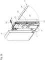
- Fig. 6a to 6b show alternative configurations of a side wall 2 of a drawer 1 as an example of a push element according to the application for a piece of furniture.
- the wall element 22 is not integrated directly into the side wall 2 here, but is held by supports 25 which are arranged on longitudinal supports 21 of the side wall 2.
- the carriers 25 thus perform a similar function as the connecting element 24 with the cover 23.
- the carriers 25 can also be retrofitted in order to be able to supplement originally flat side walls 2 with the wall element 22.
- a lighting device is integrated into the supports 25, which illuminate the side of the wall element 22.
- the second horizontal narrow surface 224 points upwards and thus creates the desired illumination effect.
- the side wall is designed without a lighting device and the wall element 22 is rotated through 180° about the horizontal axis so that the first horizontal narrow surface 222 points upwards.
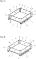
- the 7a and 7b show a further exemplary embodiment of a push element designed as a drawer 1.
- Both the side walls 2 and the rear wall 3 and the front wall 4 each have a wall element 22.
- lighting devices for example again LEDs 243, are integrated in the connecting elements 24, which light up laterally in the wall element 22.
- the second horizontal narrow surface 224 points upwards and thus creates the desired illumination effect on the side walls 2, the rear wall 3 and the front wall 4.
- connecting elements 24 are designed without a lighting device and the wall elements 22 are rotated through 180° about the horizontal axis, so that the first horizontal narrow surfaces 222 point upwards.
Landscapes
- Drawers Of Furniture (AREA)
- Arrangement Of Elements, Cooling, Sealing, Or The Like Of Lighting Devices (AREA)
Description
- Die Erfindung betrifft ein Schubelement für ein Möbel, insbesondere einen Schubkasten, aufweisend mindestens eine Wand, die zumindest abschnittsweise von einem lichtdurchlässigen Wandelement gebildet ist, wobei das Wandelement zwei gegenüberliegende Schmalflächen aufweist. Die Erfindung betrifft weiterhin ein Möbel mit einem derartigen Schubelement.
- Schubelemente der oben genannten Art sind beispielsweise Schubkästen, auch Schubladen genannt, die in der Regel als Wände neben Seitenwänden noch eine Rückwand und eine dem Benutzer zugewandte Frontwand, häufig nur Front genannt, aufweisen. Aus Designgründen, aber auch zur bequemeren Nutzbarkeit eines solchen Schubelements, sind Ausgestaltungen bekannt, bei denen zumindest eine der genannten Seiten-, Rück- oder Frontwände teilweise lichtdurchlässig ist, z.B. indem sie abschnittweise von einem lichtdurchlässigen Wandelement gebildet ist. Dabei kann zusätzlich vorgesehen sein, Beleuchtungsvorrichtungen, insbesondere LEDs (Leuchtdioden), so anzuordnen, dass sie von einer Schmalfläche des Wandelements her in dieses einstrahlen. Aufgrund innerer Reflektion breitet sich das Licht über die gesamte Fläche des Wandelements aus und verlässt das Wandelement teilweise über die Seitenflächen, also die Wandflächen, und teilweise über die Schmalflächen, auch Stirnflächen des Wandelements genannt. Auf diese Weise kann eine ansprechende Ausleuchtung des Innenraums des Schubelements erfolgen.
- Eine derartige Anordnung ist beispielsweise aus der Druckschrift
DE 20 2009 000 472 U1 bekannt. Die Schrift beschreibt ein Einstrahlen von Licht bevorzugt durch eine Beleuchtungseinrichtung, die entlang der oberen Schmalfläche angeordnet ist. Alternativ wird eine Einstrahlung auch von der unteren horizontalen Schmalfläche oder auch von den vertikalen Schmalflächen beschrieben . Der Stand der Technik ist auch ausWO 2010/023047 undDE 20 2015 100770 U1 bekannt. - Bei einem Einstrahlen entlang der oberen horizontalen Schmalfläche in das Wandelement ist diese Schmalfläche folglich von der Beleuchtungseinrichtung verdeckt und stellt keine optisch wirkende Lichtaustrittsfläche dar. Bei einem Einstrahlen in eine vertikale Schmalfläche oder in die untere horizontale Schmalfläche kann die obere Schmalfläche frei bleiben, so dass sie auch als Lichtaustrittsfläche dient. Je nach persönlichem Empfinden eines Anwenders kann das dort austretende Licht abhängig von seiner Intensität und auch der Abstrahlcharakteristik als störend empfunden werden. Andere Nutzer wiederum sehen in einer solchen Abstrahlung einen besonders interessanten Lichteffekt.
- Es ist eine Aufgabe der vorliegenden Erfindung, ein Schubelement der eingangs genannten Art zu schaffen, bei dem ein Benutzer selbst auf einfache Art und Weise zwischen verschiedenen Effekten an der oberen Schmalfläche des Wandelements auswählen kann.
- Diese Aufgabe wird durch ein Schubelement und ein Möbel mit einem solchen Schubelement mit den Merkmalen des jeweiligen unabhängigen Anspruchs gelöst. Vorteilhafte Ausgestaltungen und Weiterbildungen sind jeweils Gegenstand der abhängigen Ansprüche.
- Ein erfindungsgemäßes Schubelement der eingangs genannten Art zeichnet sich dadurch aus, dass das lichtdurchlässige Wandelement aus der Wand entnehmbar ist und um eine horizontale Achse um 180° gedreht wiedereinsetzbar ist, wobei die beiden in der Einbaulage horizontalen Schmalflächen des Wandelements unterschiedliche optische Eigenschaften aufweisen.
- Durch die Auswahl der einen oder der anderen horizontalen Schmalfläche kann das optische Erscheinungsbild, insbesondere in einer Beleuchtungssituation, variiert werden. Dadurch, dass das Wandelement entnehmbar in der Wand aufgenommen ist, kann der Benutzer selbst einen Wechsel je nach Vorliebe vornehmen.
- In einer vorteilhaften Ausgestaltung des Schubelements weisen die beiden in der Einbaulage horizontalen Schmalflächen im Bereich ihrer Oberfläche eine Struktur auf, die eine unterschiedliche Lichtstreuung erzeugt. Bevorzugt ist eine der horizontalen Schmalflächen nach einem Behandlungsverfahren hergestellt und die andere horizontale Schmalfläche entweder nach einem anderen Behandlungsverfahren oder dem gleichen Behandlungsverfahren wie die erstgenannte Schmalfläche, dann allerdings mit anderen Kennwerten. Erfindungsgemäß ist eine der horizontalen Schmalflächen poliert sein, wohingegen die gegenüberliegende horizontale Schmalfläche aufgeraut, insbesondere satiniert ist. Die polierte Schmalfläche ermöglicht einen maximalen Lichtaustritt nach oben im Betrieb. Die aufgeraute, insbesondere satinierte Fläche verhindert vorteilhaft einen Lichtaustritt nicht vollständig, aber führt zu einem sanfteren und blendfreieren Lichtaustritt.
- In einer weiteren vorteilhaften Ausgestaltung ist die aufgeraute Schmalfläche beschichtet, so dass sie vor einem Fettfilm z.B. durch Fingerabdrücke geschützt ist. Durch Beschichtung behält die aufgeraute Oberfläche ihren optischen Streueffekt für das Licht.
- In weiteren vorteilhaften Ausgestaltungen können andere Oberflächenbehandlungen an zumindest einer der Schmalflächen vorgesehen sein, beispielsweise eine geometrische Strukturierung, eine Abdeckung durch ein mehr oder weniger durchscheinendes Abdeckmaterial, beispielsweise einen Lack und/oder eine Kolorierung, z.B. durch in das Material des Wandelements eingedrungene Farbstoffe. Geeignete Behandlungsverfahren sind z.B. Coatingverfahren, organischer oder keramischer Siebdruck, Folieren, Fräsen, Schleifen, Gravieren, Strahlverfahren z.B. Sandstrahlen oder Glasperlenstrahlen, Ätzverfahren, Lasergravur, oder Säumen.
- In einer weiteren vorteilhaften Ausgestaltung sind auch die parallelen gegenüberliegenden Seitenflächen des Wandelements optisch unterschiedlich ausgebildet. Durch die unterschiedliche Ausbildung kann ein Erscheinungsbild des Schubkastens nach außen je nach Einbaulage des Wandelements variiert werden. Welche der beiden Seitenflächen innen im Schubelement und welche außen liegt, kann durch Drehung des Wandelements um 180° um eine vertikale Achse ausgewählt werden. In Kombination mit einer Drehung um zuvor genannte horizontale Achse, kann so jedes Wandelement in insgesamt vier sich vom optischen Erscheinungsbild her unterschiedlichen Einbaulagen verwendet werden.
- Vorteilhaft wird dabei ein unterschiedliches Erscheinungsbild der beiden Seitenflächen durch eine Strukturierung erzielt. Eine unterschiedliche Strukturierung führt zu unterschiedlich anmutenden Lichtauskopplungen.
- In einer weiteren vorteilhaften Ausgestaltung ist das Wandelement aus zwei parallel aufeinandergelegten Wandelementen aufgebaut. Insbesondere in Kombination mit einer Strukturierung oder unterschiedlichen Ausgestaltung der nunmehr vier vorliegenden Seitenflächen kann die Variationsmöglichkeit des optischen Erscheinungsbilds insbesondere in einer Beleuchtungssituation weiter erhöht werden. Auch kann zwischen den beiden Flächenelementen eine Dekorfolie angeordnet sein, auf der sich z.B. ein Muster befindet, dass insbesondere bei einer Beleuchtung durch die Beleuchtungsvorrichtung sichtbar wird.
- In einer weiteren vorteilhaften Ausgestaltung kann auch eine Gravur in das Wandelement eingebracht werden, die insbesondere in einer Beleuchtungssituation sichtbar wird.
- Das Wandelement kann in einer Seitenwand oder in beiden Seitenwänden vorgesehen sein, oder zusätzlich oder ausschließlich in der Front und/oder der Rückwand angeordnet werden.
- In einer weiteren vorteilhaften Ausgestaltung ist dem Wandelement eine Beleuchtungsvorrichtung zugeordnet, wobei die Beleuchtungsvorrichtung wenigstens in eine der horizontalen Schmalflächen oder eine vertikale Schmalfläche einstrahlt. Ein Einstrahlen in eine oder beide vertikalen Schmalflächen ist insofern vorteilhaft, als dass sich optischen Eigenschaften der Fläche, in die eingestrahlt wird, bei einem Drehen des Wandelements um 180° um eine horizontale Achse nicht ändern, so dass in jeder der beiden Betriebspositionen gleiche Bedingungen für das Einstrahlen des Lichts vorliegen. Bevorzugt weist die Beleuchtungsvorrichtung mindestens eine LED oder eine OLED (organische LED) auf.
- In einer weiteren vorteilhaften Ausgestaltung ist dem Schubelement eine Steuereinrichtung zur Steuerung der Beleuchtungsvorrichtung zugeordnet. Bevorzugt ist die Steuereinrichtung dazu ausgebildet, die Beleuchtungsvorrichtung nach dem Prinzip des Human Centric Lighting anzusteuern. Dieses Beleuchtungskonzept berücksichtigt die visuellen, emotionalen und biologischen Wirkungen des Lichts. Durch die Steuereinrichtung werden zumindest die Farbtemperatur und die Beleuchtungsintensität über den Tagesverlauf gesteuert. Weiter kann eine Anordnung aus einer Beleuchtungsvorrichtung, einer Steuereinheit und einem Schubelement für ein Möbel gebildet sein, wobei das Schubelement auszeichnet, dass es mindestens eine Wand aufweist, die zumindest abschnittsweise von einem lichtdurchlässigen Wandelement gebildet ist, wobei das Wandelement gegenüberliegende Schmalflächen aufweist, wobei die Beleuchtungsvorrichtung wenigstens in eine Schmalfläche des Wandelements einstrahlt und wobei die Beleuchtungsvorrichtung nach dem Prinzip des Human Centric Lighting ausgebildet ist.
- Weiter bevorzugt weist die Steuereinheit eine drahtlose Datenschnittstelle auf, wobei die drahtlose Datenschnittstelle mit wenigstens einer internetfähigen Zentrale kommuniziert und wobei die Zentrale mit weiteren Artfremden Geräten kommuniziert, wobei die artfremden Geräte eine Aktion der Steuereinheit der Beleuchtungsvorrichtung auslösen können oder die Steuereinheit der Beleuchtungsvorrichtung eine Aktion der artfremden Geräte auslöst. Die drahtlose Datenschnittstelle kann ein Mesh-Netzwerk mit weiteren drahtlosen Datenschnittstellen anderer Geräte bzw. Beleuchtungsvorrichtungen bilden. Die Zentrale kann von einem Smart Home-System gebildet sein oder in dieses eingebunden sein. Diese Ausgestaltung kann sowohl bei dem erfindungsgemäßen Schubelement, als auch bei der zuvor genannten Anordnung aus Beleuchtungsvorrichtung, Steuereinrichtung und Schubelement umgesetzt sein.
- In einer weiteren vorteilhaften Ausgestaltung kann das Wandelement in der Wand durch eine Verriegelung gesichert sein. Auf diese Weise kann das Schubelement bei der Montage auch an den Wandelementen angehoben werden, ohne dass die Wandelemente herausrutschen.
- Ein erfindungsgemäßes Möbel zeichnet sich durch den Einsatz mindestens eines derartigen Schubelements aus. Es ergeben sich die im Zusammenhang mit dem Schubelement genannten Vorteile. Das Schubelement kann dabei insbesondere als Schubkasten, auch Schublade genannt, ausgebildet sein.
- Die Erfindung wird nachfolgend anhand von Ausführungsbeispielen mit Hilfe von Figuren näher erläutert. Die Figuren zeigen:
- Fig. 1
- eine isometrische Gesamtansicht eines Schubkastens als Schubelement eines Möbels;
- Fig. 2
- eine Seitenwand des Schubkastens aus
Fig. 1 , separat vom Schubkasten als isometrische Teil-Explosionsdarstellung wiedergegeben; - Fig. 3a, b
- jeweils eine isometrische Detailansicht eines Abschnitts der Seitenwand in verschiedenen Verriegelungszuständen;
- Fig. 4
- zwei isometrische Teildarstellungen der Seitenwand des Schubkastens aus verschiedenen Blickrichtungen;
- Fig 5a, b
- zwei Ausgestaltungen eines durchscheinenden Wandelements für den Schubkasten gemäß
Fig. 1 bzw. die Seitenwand derFig. 2-4 ; - Fig. 6a-c
- drei Ausgestaltungen einer Seitenwand mit einem Aufsatz mit und ohne Beleuchtungsvorrichtung als isometrische Teil-Explosionsdarstellung; und
- Fig. 7a, b
- zwei Ausgestaltungen einer isometrischen Gesamtansicht eines Schubkastens mit und ohne Beleuchtungsvorrichtung.
- In allen Figuren kennzeichnen gleiche Bezugszeichen gleiche oder gleichwirkende Elemente. Aus Gründen der Übersichtlichkeit ist in den Figuren nicht jedes Element in allen Figuren mit einem Bezugszeichen versehen.
- In der Beschreibung beziehen sich Begriffe wie "oben, unten, links, rechts" zunächst auf die in den jeweiligen Figuren gewählte beispielhafte Darstellung. Im Hinblick auf die Begriffe "oben" und "unten" deckt sich in Verbindung mit einem Schubkasten die Darstellung in den Figuren mit der üblicherweise im Raum eingenommenen Ausrichtung, bei der ein Boden des Schubkastens horizontal ausgerichtet ist und der Schubkasten nach oben offen ist. Die Begriffe "vorne" und "hinten" sind auf eine Auszugsrichtung einer Auszugsführung des Schubkastens gerichtet.
-
Fig. 1 zeigt einen Schubkasten 1 als Beispiel eines anmeldungsgemäßen Schubelements für ein Möbel. - Der Schubkasten 1 gemäß
Fig. 1 weist insgesamt vier Wände 2, 3, 4 auf, darunter zwei parallele Seitenwände 2, eine Rückwand 3 und eine Frontwand 4, auch als Front 4 bezeichnet. Die genannten Wände 2-4 umgeben einen Boden 5. - Im dargestellten Beispiel sind die Seitenwände 2 mehrteilig ausgebildet. Sie umfassen jeweils einen unten an der Seitenwand 2 angeordneten Längsträger 21 auf den ein flächiges Wandelement 22 aufgesetzt ist. Seitlich ist das Wandelement 22 von zwei Abdeckungen 23 eingerahmt, die Verbindungselemente 24 abdecken, an denen die Seitenwand 2 mit der Rückwand 3 bzw. der Front 4 verbunden ist.
- Die Rückwand 3 sowie die Abdeckungen 23 sind in diesem Ausführungsbeispiel aus einem Blechmaterial in einem Stanz-Biege-Prozess erstellt. Die Front 4 und der Boden 5 können beispielsweise aus Holz oder einem Holzwerkstoff oder auch Kunststoff hergestellt sein, aber auch beispielsweise aus Metall.
- Grundsätzlich können nicht nur die Seitenwände 2, sondern auch oder ausschließlich die Rückwand 3 und/oder die Frontwand 4 mehrteilig mit einem einsetzbaren Wandelement 22 ausgebildet sein. Ein Ausführungsbeispiel, bei dem alle Wände 2-4 derart ausgebildet sind, ist beispielsweise in den
Fig. 7a, b gezeigt. - Die aus mehreren Abschnitten zusammengesetzte Seitenwand 2 ist in der
Fig. 2 separat vom Schubkasten 1 in einer isometrischen Zeichnung detaillierter wiedergegeben. Bei der Darstellung derFig. 2 sind die Abdeckungen 23 in Art einer Explosionsdarstellung von der Seitenwand abgenommen wiedergegeben, um den Aufbau des Verbindungselements 24 zu zeigen, das ansonsten von der Abdeckung 23 verdeckt ist. - Die Verbindungselemente 24 sind fest mit dem Längsträger 21 verbunden und können auch mit Komponenten des Längsträgers einstückig ausgebildet sein. Die Verbindungselemente 24 umfassen Komponenten, mit denen eine ggf. rastende Verbindung zur Rückwand 3 bzw. zur Front 4 hergestellt werden kann. Dabei können Einstellelemente vorhanden sein, die z.B. eine Änderung der Höhen- und/oder Seitenposition der Front 4 gegenüber den Seitenwänden 2 ermöglichen, um beispielsweise Spaltmaße im Frontbereich eines Möbels einstellen zu können. Unterhalb des Längsträgers 21 kann der Schubkasten 1 mit einer Laufschiene einer Auszugsführung gekoppelt werden, um den Schubkasten 1 aus dem Möbel ausfahren zu können.
- Das Wandelement 22 wird von dem Längsträger 21 und den Verbindungselementen 24 u-förmig entlang von drei Schmalflächen umrahmt. Seitenflächen 221 des Wandelements 22 sowie eine obere horizontale Schmalfläche 222 liegen frei. An den Verbindungselementen 24 sind zur Aufnahme des Wandelements 22 u-förmige Aufnahmeschienen 241 angeordnet, in die das Wandelement 22 von oben eingeschoben werden kann, wenn ein Verriegelungsteil 242 zur Seite geschwenkt ist.
- Die
Fig. 3a und3b zeigen den Bereich der Aufnahmeschiene 241 am Verbindungselement 24 sowie das Verriegelungsteil 242 detaillierter. In dem gezeigten Beispiel ist das Verriegelungsteil 242 als ein schwenkbar gelagerter Hebel ausgebildet. In einer alternativen Ausgestaltung kann das Verriegelungsteil 242 beispielsweise auch als Schieber ausgeführt sein. - In
Fig. 3a ist das Verriegelungsteil 242 ausgeschwenkt, so dass das Wandelement 22, das in denFig. 3a und3b beabstandet von der Aufnahme 241 dargestellt ist, eingeschoben werden kann. Nach einem Einschwenken des Verriegelungsteils 242 (vgl.Fig. 3b ) wird das Wandelement 22 von diesem im Eckbereich oben übergriffen und ist dadurch zwischen den beiden Verbindungselementen 24 festgelegt. Nach einem Aufsetzen der Abdeckung 23 auf das Verbindungselement 24 ist zudem das Verriegelungsteil 242 nicht mehr zugänglich und in seiner geschlossenen Position fixiert. - Die geschlossene Position des Verrieglungsteils 242 ist in den beiden Detailausschnitten der
Fig. 4 aus zwei unterschiedlichen Blickrichtungen nochmals wiedergegeben. In diesen beiden Detailausschnitten ist das Wandelement 22 (anders als in denFig. 3a ,b ) in seiner korrekten und in die Aufnahmeschiene 241 eingesetzten Position gezeigt. - Das Wandelement 22 ist lichtdurchlässig, beispielsweise transparent, zumindest aber transluzent. Im Bereich der Aufnahmeschiene 241 sind Leuchtdioden (LEDs) 243 als Beleuchtungsvorrichtungen angeordnet, die über ein Verbindungskabel mit einem Stecker 244 mit Betriebsstrom versorgt werden können. Die LEDs 243 sind somit so positioniert, dass sie Licht in eine vertikale Schmalfläche 223 des Wandelements 22 einstrahlen. Derartige LEDs 243 können an einem oder auch an beiden Verbindungselementen 24 angeordnet sein, so dass in das Wandelement 22 von einer oder von zwei gegenüberliegenden Seiten Licht eingestrahlt wird.
- Eine Stromversorgung der Beleuchtungsvorrichtungen kann beispielsweise über einen Energiespeicher erfolgen, der am Schubkasten 1 angeordnet ist. Dieser kann beispielsweise an der Außenseite der Rückwand 3, innerhalb der Verbindungselemente 24, im Inneren des Schubkastens oder unterhalb des Bodens 5 angeordnet sein.
- Als Energiespeicher kann beispielsweise eine wiederaufladbare oder eine nicht wiederaufladbare Batterie oder ein Kondensator mit hoher Kapazität, englisch auch Supercap oder Supercapacitor genannt, eingesetzt werden. Wenn der Energiespeicher wiederaufladbar ist, kann ein extern vom Schubkasten 1 angeordnetes Netzteil vorhanden sein, um den Energiespeicher wieder aufzuladen. Bevorzugt wird dabei eine Verbindung vom Netzteil zum Energiespeicher bei eingefahrenem Schubkasten 1 hergestellt. Die Verbindung kann z.B. über entsprechende Kontakte an der Rückwand 3 des Schubkastens 1 erfolgen, die zugeordnete Gegenkontakte in dem Möbelkorpus, in dem der Schubkasten 1 angeordnet ist, bei eingefahrenem Schubkasten 1 kontaktieren. Das Netzteil kann eigens für diesen Zweck vorhanden sein. Wenn verfügbar, kann auch ein bereits vorhandenes Netzteil, z.B. eines Schubkastenantriebs, das an dem Möbel angeordnet ist, mitgenutzt werden. Um diesbezüglich möglichst flexibel zu sein, kann eine Ladeschaltung für den Energiespeicher als Weitbereichsgerät ausgeführt sein, das Eingangsspannungen in einem weiten Spannungsbereich und als Gleich- oder Wechselspannung toleriert und eine konstante Ausgangsspannung für den Ladevorgang ausgibt.
- Es kann weiter eine Steuereinrichtung vorhanden sein, die eine Öffnung des Schubkastens 1 detektiert und die LEDs 243 bei geöffnetem Schubkasten 1 anschaltet. Eine Detektion des geöffneten Zustands kann z.B. über einen Magnetsensor (Reed-Kontakt oder Hall-Sensor) erfolgen. Der Magnetsensor kann am Schubkasten 1 angeordnet sein und mit einem am Möbelkorpus ortsfesten Magneten wechselwirken. Auch ein Schalten über einen mechanisch abtastenden Tastschalter, einen Bewegungssensor, einen Beschleunigungssensor oder optisch über eine Lichtschranke ist denkbar.
- Wenn bei eingefahrenem Schubkasten 1 eine Verbindung zu einem Netzteil zum Laden des Energiespeichers etabliert wird, kann diese Kontaktierung auch ausgewertet werden und die gewonnene Information zum Einschalten der LEDs 243 herangezogen werden. Aus kann auch vorgesehen sein, dass die Beleuchtung nach einer vorgegebenen oder einstellbaren Zeit ausgeschaltet wird, wenn der Schubkasten nicht geschlossen wird.
- Anstelle eines Energiespeichers kann aber auch eine Stromschiene vorgesehen sein, durch die der Schubkasten 1 dauerhaft mit Strom versorgt wird. In einer Ausgestaltung können die Auszugsführungen als Stromschienen eingesetzt werden.
- Die Beleuchtungsvorrichtung kann mehrere LEDs 243 aufweisen, die entweder gleiche optische Eigenschaften (z.B. Farbe, Farbtemperatur, Intensität) haben oder unterschiedliche. Es kann vorgesehen sein, dass LEDs 243 mit unterschiedlichen Eigenschaften von der Steuereinrichtung selektiv angesteuert werden können. Werden z.B. warmweiße und kaltweiße LEDs 243 eingesetzt, deren Helligkeit unabhängig voneinander eingestellt werden kann, kann Weißlicht mit unterschiedlicher Farbtemperatur additiv gemischt werden. Anstelle von oder zusätzlich zu warmweißen und kaltweißen LEDs können auch farbige LEDs bei der Beleuchtungsvorrichtung vorgesehen sein, insbesondere rote, grüne und blaue LEDs, um durch Farbmischung einen großen Farbraum abzudecken. Die roten, grünen und blauen LEDs können separate LEDs sein oder auch in Form sogenannter RGB-LEDs verwendet werden, die Leuchtchips der drei genannten Farben in einem Gehäuse vereinen.
- Zum Einstellen der Farbtemperatur (oder Farbe) können Steuerelemente an der Steuereinrichtung vorhanden sein, oder diese kann alternativ oder zusätzlich mit einer drahtlosen Datenschnittstelle versehen sein.
- Eine drahtlose Datenschnittstelle kann beispielsweise über WLAN, Bluetooth, ZigBee, ZWAVE und z.B. auf den Frequenzen 433 MHz oder 868 MHz oder anderen geeigneten Frequenzen erfolgen. Als Protokolle können auch KNX oder IP eingesetzt werden. Die Vorrichtung kann mit externen Geräten kommunizieren und zum Beispiel "Smart Home"-fähig sein und auch über Sprachsteuerung angesteuert werden.
- Bei einer Anwendung im Sinne eines Smart Home-Systems können z.B. verschiedene Schubkästen untereinander vernetzt sein oder mit einer Smart Home-Zentrale gekoppelt sein. Damit ist es z.B. möglich, dass nur der oberste geöffnete Schubkasten beleuchtet wird, falls zwei übereinander angeordnete Schubkästen geöffnet sind. Alternativ könnten beide Schubkästen beleuchtet werden, sofern die Front des unteren Schubkastens vor der des darüber liegenden Schubkastens steht, wobei Positionen des Schubkastens über entsprechende Sensorik erfasst werden.
- Weiter kann eine Warnfunktion (z.B. vor einer Kippgefahr) umgesetzt sein, die ein Blinken o.ä. der Beleuchtungsvorrichtung eines Schubkastens veranlasst, wenn z.B. mehr als ein Schubkasten in einem Möbel ausgezogen wird.
- Alternativ oder zusätzlich könnte die Beleuchtungsvorrichtung bzw. mit der zugeordneten Steuereinrichtung gekoppelte Sensoren auch ein Teil einer Smart Home-Alarmanlage sein und z.B. eine Sirene auslösen oder eine Nachricht an eine Person senden.
- Weiter kann eine Meldefunktion in einem Smart Home System umgesetzt sein, die ebenfalls ein Blinken o.ä. der Beleuchtungsvorrichtung eines Schubkastens veranlasst, wenn z.B. die Türklingel betätigt wird oder das Telefon klingelt. Dabei können sich die Lichteffekte unterscheiden. Eine Betätigung der Türklingel kann beispielsweise ein Blinken der Beleuchtungsvorrichtung verursachen, während ein Klingeln des Telefons ein Lauflicht der Beleuchtungsvorrichtung verursachen kann.
- Ebenfalls als Teil eines Smart Home Systems oder auch lokal in der Steuereinrichtung umgesetzt könnte eine automatische tageszeitliche Änderung der Farbtemperatur und/oder der Intensität der Beleuchtungsvorrichtung erfolgen. Die Beleuchtungsvorrichtung kann z.B. gemäß den Konzepten des Human Centric Lighting (HCL) ausgebildet sein. Das Human Centric Lighting umfasst ein Beleuchtungskonzept bei dem die visuellen, emotionalen und biologischen Wirkungen des Lichts berücksichtigt werden.
- Innerhalb des Wandelements 22 wird das Licht der Beleuchtungsvorrichtung durch Reflektion an den inneren Flächen der Seitenflächen 221 weitergeleitet und verlässt die Wandflächen zum Teil durch die Seitenflächen 221 und zum Teil durch die obere horizontale Schmalfläche 222, wodurch ein gewünschter Illuminationseffekt erzielt wird.
- Anmeldungsgemäß kann durch die Art der Montage des Wandelements 22 durch Einschieben in die Aufnahmeschienen 241 das Wandelement 22 leicht auch vom Benutzer entnommen werden. Es ist dabei so ausgebildet, dass es um 180° um eine horizontale Achse gedreht wiedereingesetzt werden kann, so dass die der zuvor oberen horizontalen Schmalfläche 222 gegenüberliegende andere horizontale Schmalfläche 224 (vgl.
Fig. 5a ) dann oben liegt und sichtbar ist. Anmeldungsgemäß sind die beiden horizontalen Schmalflächen 222, 224 optisch unterschiedlich ausgebildet, so dass ein anderer Effekt oder Eindruck bei der Beleuchtung erzielt wird. Es kann vorgesehen sein, dass ein Adapter verwendet wird, um z.B. ein schmaleres Wandelement 22 aufzunehmen. Dabei kann der Adapter ebenfalls transparente Merkmale oder Aussparungen aufweisen, um einen Effekt oder Eindruck zu erzielen. - Dieses ist in
Fig. 5a für eine erste Ausgestaltung eines Wandelements 22 gezeigt. In der Mitte der Figur ist eine Draufsicht auf die Seitenfläche 221 des Wandelements 22 gezeigt. Links und rechts sind Draufsichten auf die beiden in Einbaulage horizontalen Schmalflächen 222, 224 gezeigt, nämlich links auf die bereits in den zuvor beschriebenen Figuren sichtbare erste horizontale Schmalfläche 222 und rechts auf eine zweite, der ersten gegenüberliegende horizontale Schmalfläche 224. Erfindungsgemäß ist die erste horizontale Schmalfläche 222 eine polierte Fläche und die zweite horizontale Schmalfläche 224 eine aufgeraute, insbesondere satinierte Oberfläche. Das Wandelement 22 kann aus Glas oder einem durchscheinenden Kunststoff, z.B. Plexiglas beispielsweise einem Kunststoff der Polycarbonat enthält, hergestellt sein. Der unterschiedliche Rauheitsgrad der Schmalflächen 222, 224 führt zu einer Lichtabstrahlung in unterschiedlicher Intensität und mit unterschiedlichem Abstrahlprofil. - Neben Polieren bzw. Satinieren können auch andere Oberflächenbehandlungen an einer oder beiden Schmalflächen 222, 224 vorgenommen werden, durch die sich die Schmalflächen 222, 224 optisch unterscheiden. Beispiele sind eine geometrische Strukturierung, eine Abdeckung durch ein mehr oder weniger durchscheinendes Abdeckmaterial, beispielsweise einen Lack und/oder eine Kolorierung, z.B. durch in das Material des Wandelements eindiffundierte Farbstoffe. Alternativ kann auch eine Lasergravur im Randbereich der Schmalflächenbeschichtung 222, 224 vorgenommen werden, um unterschiedliche Illuminationseffekte zu erzeugen.
- In
Fig. 5b ist in gleicher Weise wie inFig. 5a eine zweite Ausgestaltung eines Wandelements 22 dargestellt, das in gleicher Weise alternativ in dem Schubkasten 1 der zuvor gezeigten Figuren eingesetzt werden kann. Bei diesem Ausführungsbeispiel ist das Wandelement 22 aus zwei aufeinandergelegten Flächenelementen 22a und 22b zusammengesetzt. Wie beim Beispiel derFig. 5a können die in Einbaulage horizontalen Schmalflächen 222a, b bzw. 224 a, b der beiden Flächenelemente unterschiedlich ausgebildet sein, beispielsweise wiederum poliert bzw. satiniert. Eine oder auch beide der Flächenelemente 22a, b können Strukturierungen, z.B. Gravuren, auf ihren Seitenflächen aufweisen, insbesondere auf den zueinander weisenden innen liegenden Flächen. Alternativ oder zusätzlich kann auch eine Dekorfolie zwischen den Flächenelementen 22a, b angeordnet sein. Sich im Inneren des Wandelement ausbreitendes Licht wird an diesen Strukturierungen bzw. der Dekorfolie gestreut, so dass bei Beleuchtung Ornamente 225 auftreten, die in einem nicht-beleuchteten Zustand nicht oder nur marginal sichtbar sind. Auf diese Weise können weitere Lichteffekte erzeugt werden. - Dabei können die beiden Flächenelemente 22a, b untrennbar zusammengefügt sein. Es ist jedoch auch möglich, dass die beiden Flächenelemente 22a, b nur aufeinandergelegt sind, was die Möglichkeit eröffnet, die Strukturierungen innen oder außen anzuordnen, wodurch sich der erzielte Effekt nochmal verändert. Dadurch wird eine weitere Variationsmöglichkeit von Lichteffekten für den Benutzer gegeben.
- Die Innen- oder Außenflächen der Seitenflächen 221 der Wandelemente 22, 22a, 22b können als Dekorfläche dienen und können durch unterschiedliche Bearbeitung gestaltet sein. Die Seitenfläche 221 können z.B. durch ein Coatingverfahren - aufbringen einer Pulverbeschichtung - oder durch ein Printingverfahren - aufbringen eines organischen oder keramischen Siebdrucks - oder aufbringen einer Folie gestaltet sein. Die Seitenflächen 221 können auch mechanisch bearbeitet sein. Eine mechanische Bearbeitung kann z.B. durch fräsen, schleifen, gravieren oder unterschiedliche Strahlverfahren z.B. Sandstrahlen oder Glasperlenstrahlen oder ein Ätzverfahren mit Flusssäure erfolgen. Alternativ oder zusätzlich zu einer Oberflächenbehandlung der Seitenfläche 221 kann auch eine Struktur innerhalb des Wandelements 22, 22a, 22b eingebracht sein. Die dekorative Struktur kann z.B. durch eine Lasergravur eingebracht werden. Durch die Lasergravur sind z.B. auch 3D-Modelle innerhalb der Wandfläche 22, 22a, 22b möglich. Somit können z.B. Logos, Beschriftungen, Bilder in 2D oder 3D eingebracht werden. Die Seitenfläche 221 kann somit durch eine oder mehrere der hier aufgeführten Gestaltungsmöglichkeiten gestaltet sein. Zwischen den Wandelementen 22a, 22b können alternativ auch flache Elemente wie z.B. Fotos eingebracht sein.
-
Fig. 6a bis 6b zeigen alternative Ausgestaltungen einer Seitenwand 2 eines Schubkastens 1 als Beispiel eines anmeldungsgemäßen Schubelements für ein Möbel. Das Wandelement 22 ist hier jedoch nicht unmittelbar in der Seitenwand 2 integriert, sondern durch Träger 25 gehalten, die auf Längsträger 21 der Seitenwand 2 angeordnet sind. Die Träger 25 übernehmen somit eine ähnliche Funktion wie das Verbindungselement 24 mit der Abdeckung 23. Insbesondere können die Träger 25 darüber hinaus nachrüstbar sein, um ursprünglich flache Seitenwände 2 um das Wandelement 22 ergänzen zu können. - In der
Figur 6a ist eine Beleuchtungsvorrichtung in den Trägern 25 integriert, die seitlich in das Wandelement 22 leuchten. Die zweite horizontale Schmalfläche 224 zeigt hier nach oben und erzeugt so den gewünschten Illuminationseffekt. - In der
Figur 6b ist die Seitenwand ohne Beleuchtungsvorrichtung ausgeführt und das Wandelement 22 um 180° um die horizontale Achse gedreht, so dass die erste horizontale Schmalfläche 222 nach oben weist. - Bei dem Beispiel der
Figur 6c ist die Seitenwand 2 mit den Trägern 25 analog derFiguren 6a und 6b ausgeführt. Bei derFigur 6c ist im Unterschied zu der Figur 6a die Beleuchtungseinrichtung unterhalb des Wandelements 22 angeordnet. - Die
Fig. 7a und 7b zeigen ein weiteres Ausführungsbeispiel eines als Schubkasten 1 ausgebildeten Schubelements. Hierbei weisen sowohl die Seitenwände 2 als auch die Rückwand 3 und die Frontwand 4 jeweils ein Wandelement 22 auf. - Bei der
Figur 7a sind Beleuchtungsvorrichtungen, z.B. wiederum LEDs 243, in den Verbindungselementen 24 integriert, die seitlich in das Wandelement 22 leuchten. Die zweite horizontale Schmalfläche 224 zeigt hier nach oben und erzeugt so bei den Seitenwänden 2, der Rückwand 3 und der Frontwand 4 den gewünschten Illuminationseffekt. - In der
Figur 7b sind die Verbindungselemente 24 ohne Beleuchtungsvorrichtung ausgeführt und die Wandelemente 22 um 180° um die horizontale Achse gedreht, so dass die ersten horizontalen Schmalflächen 222 nach oben weisen. -
- 1
- Schubkasten
- 2
- Wand (Seitenwand)
- 21
- Längsträger
- 22
- Wandelement
- 22a, b
- Flächenelement
- 221
- Seitenfläche
- 222
- erste horizontale Schmalfläche (poliert)
- 222a, b
- erste horizontale Schmalfläche (poliert)
- 223
- vertikale Schmalfläche
- 224
- zweite horizontale Schmalfläche (satiniert)
- 224a, b
- zweite horizontale Schmalfläche (satiniert)
- 225
- Ornament
- 23
- Abdeckung
- 24
- Verbindungselement
- 241
- Aufnahmeschiene
- 242
- Verriegelung
- 243
- LED
- 244
- Stecker
- 25
- Träger
- 3
- Wand (Rückwand)
- 4
- Wand (Frontwand)
- 5
- Boden
Claims (17)
- Schubelement für ein Möbel, aufweisend mindestens eine Wand (2, 3, 4), die zumindest abschnittsweise von einem lichtdurchlässigen Wandelement (22) gebildet ist, wobei das Wandelement (22) zwei gegenüberliegende Schmalflächen (222, 224) aufweist und das lichtdurchlässige Wandelement (22) aus der Wand (2, 3, 4) entnehmbar ist und um eine horizontale Achse und/oder vertikale Achse um 180° gedreht wiedereinsetzbar ist, wobei die beiden in der Einbaulage horizontalen Schmalflächen (222, 224) des Wandelements (22) unterschiedliche optische Eigenschaften aufweisen, wobei die beiden horizontalen Schmalflächen (222, 224) im Bereich ihrer Oberfläche eine Struktur aufweisen, die eine unterschiedliche Lichtstreuung erzeugt, und wobei eine der horizontalen Schmalflächen (222, 224) nach einem Behandlungsverfahren hergestellt ist und die andere horizontale Schmalfläche nach einem anderen Behandlungsverfahren oder dem gleichen Behandlungsverfahren mit anderen Kennwerten hergestellt ist, dadurch gekennzeichnet, dass die erste horizontale Schmalfläche 222 eine polierte Fläche ist und die zweite horizontale Schmalfläche eine aufgeraute Fläche ist und dass ein unterschiedlicher Rauhigkeitsgrad der Schmalflächen (222, 224) zu einer Lichtabstrahlung in unterschiedlicher Intensität und mit unterschiedlichem Abstrahlprofil führt.
- Schubelement nach Anspruch 1, wobei das Behandlungsverfahren oder das andere Behandlungsverfahren wenigstens einem der folgenden Verfahren entspricht: Coatingverfahren, organischer oder keramischer Siebdruck, Folieren, Fräsen, Schleifen, Gravieren, Strahlverfahren z.B. Sandstrahlen oder Glasperlenstrahlen, Ätzverfahren, Lasergravur, Polieren oder Säumen.
- Schubelement nach Anspruch 1 oder 2, bei dem eine der horizontalen Schmalflächen (222, 224) eine durchscheinende Abdeckung aufweist.
- Schubelement nach einem der Ansprüche 1 bis 3, bei dem das Wandelement (22) im Bereich einer der horizontalen Schmalflächen (222, 224) koloriert ist.
- Schubelement nach einem der Ansprüche 1 bis 4, bei dem Seitenflächen (221) des Wandelements (22) mit optisch unterschiedlichen Eigenschaften ausgebildet sind.
- Schubelement nach einem der Ansprüche 1 bis 5, bei dem das Wandelement (22) zwei parallel zueinander angeordnete Flächenelemente (22a, 22b) aufweist.
- Schubelement nach Anspruch 6, bei dem die Flächenelemente (22a, 22b) im Hinblick auf ihre Seitenflächen (221) mit optisch unterschiedlichen Eigenschaften ausgebildet sind.
- Schubelement nach Anspruch 6 oder 7, bei dem zwischen den Flächenelementen (22a, 22b) eine Dekorfolie angeordnet ist.
- Schubelement nach einem der vorhergehenden Ansprüche, bei dem dem Wandelement (22) eine Beleuchtungsvorrichtung zugeordnet ist, wobei die Beleuchtungsvorrichtung wenigstens in eine der horizontalen Schmalflächen (222, 223, 224) oder eine vertikale Schmalfläche (223) einstrahlt.
- Schubelement nach Anspruch 9, bei dem die Beleuchtungsvorrichtung wenigstens ein Leuchtmittel aus der Kategorie LED (243) oder OLED aufweist.
- Schubelement nach einem der Ansprüche 9 oder 10, bei dem die Beleuchtungsvorrichtung von einer Steuereinheit gesteuert wird.
- Schubelement nach Anspruch 11, bei dem die Steuereinheit eine drahtlose Datenschnittstelle aufweist, wobei die drahtlose Datenschnittstelle dazu eingerichtet ist, mit wenigstens einer internetfähigen Zentrale zu kommunizieren und wobei die Zentrale dazu eingerichtet ist, mit weiteren, artfremden Geräten zu kommunizieren, wobei die artfremden Geräte eine Aktion der Steuereinheit der Beleuchtungsvorrichtung auslösen können oder die Steuereinheit der Beleuchtungsvorrichtung eine Aktion der artfremden Geräte auslösen kann.
- Schubelement nach Anspruch 11 oder 12, bei dem die Beleuchtungsvorrichtung durch die Steuereinheit nach dem Prinzip des Human Centric Lighting gesteuert ist.
- Schubelement nach einem der vorhergehenden Ansprüche, bei dem die Wand (2, 3, 4) von einer Seitenwand (2), einer Frontwand (4), einer Rückwand (3) oder einer Wand oberhalb einer der Wände des Schubelements gebildet ist.
- Schubelement nach einem der vorhergehenden Ansprüche, bei dem das Wandelement (22) durch eine Verriegelung (242) an der Wand (2, 3, 4) gesichert ist.
- Möbel, insbesondere Schrank- oder Regalmöbel, aufweisend mindestens ein Schubelement nach einem der Ansprüche 1 bis 15.
- Möbel nach Anspruch 16, bei dem das mindestens eine Schubelement ein Schubkasten (1) ist.
Applications Claiming Priority (2)
| Application Number | Priority Date | Filing Date | Title |
|---|---|---|---|
| DE102020107663.0A DE102020107663A1 (de) | 2020-03-19 | 2020-03-19 | Möbel und Schubelement für ein Möbel |
| PCT/EP2021/056809 WO2021185902A1 (de) | 2020-03-19 | 2021-03-17 | Möbel und schubelement für ein möbel |
Publications (2)
| Publication Number | Publication Date |
|---|---|
| EP4120874A1 EP4120874A1 (de) | 2023-01-25 |
| EP4120874B1 true EP4120874B1 (de) | 2024-01-10 |
Family
ID=75111596
Family Applications (1)
| Application Number | Title | Priority Date | Filing Date |
|---|---|---|---|
| EP21713370.1A Active EP4120874B1 (de) | 2020-03-19 | 2021-03-17 | Möbel und schubelement für ein möbel |
Country Status (5)
| Country | Link |
|---|---|
| EP (1) | EP4120874B1 (de) |
| CN (1) | CN115297750A (de) |
| DE (1) | DE102020107663A1 (de) |
| ES (1) | ES2975284T3 (de) |
| WO (1) | WO2021185902A1 (de) |
Families Citing this family (5)
| Publication number | Priority date | Publication date | Assignee | Title |
|---|---|---|---|---|
| AT523987B1 (de) * | 2020-07-06 | 2022-04-15 | Blum Gmbh Julius | Haltevorrichtung zur Halterung einer auf eine Schubladenseitenwand aufsetzbaren Dekorplatte |
| AT526800B1 (de) * | 2022-12-23 | 2024-11-15 | Blum Gmbh Julius | Anordnung umfassend ein feststehendes Möbelteil, ein bewegbares Möbelteil, eine Führungsvorrichtung, eine elektrische Antriebsvorrichtung und ein Beleuchtungsmittel |
| DE102023130094A1 (de) * | 2023-10-31 | 2025-04-30 | Paul Hettich Gmbh & Co. Kg | Schubkasten und Verfahren zur Herstellung eines Schubkastens |
| US20250344852A1 (en) * | 2024-05-07 | 2025-11-13 | Juanita Mullis | Vinyl Album Storage Device |
| EP4706452A1 (de) * | 2024-09-05 | 2026-03-11 | Grass GmbH | Einrichtungselement mit beleuchtungssystem |
Family Cites Families (11)
| Publication number | Priority date | Publication date | Assignee | Title |
|---|---|---|---|---|
| US5918396A (en) * | 1996-02-16 | 1999-07-06 | Jung; Hae-Ryong | Light box with edge-lit panel |
| AT5526U1 (de) * | 2001-05-17 | 2002-08-26 | Blum Gmbh Julius | Doppelwandige schubladenzarge |
| TWM247456U (en) * | 2003-07-30 | 2004-10-21 | Hon Yu Auto Parts Co Ltd | Light guide apparatus for automobile accessory |
| AT10559U1 (de) | 2008-02-25 | 2009-06-15 | Blum Gmbh Julius | Schublade mit lichtdurchlassiger wand |
| DE202008003346U1 (de) * | 2008-03-07 | 2009-07-23 | Grass Gmbh | Möbelteil und Vorrichtung zur Erzeugung einer Lichtwirkung an einem relativ zu einem feststehenden Möbelteil bewegbaren Möbelteil |
| DE202008011548U1 (de) * | 2008-08-29 | 2010-01-07 | Paul Hettich Gmbh & Co. Kg | Möbel |
| DE202008011547U1 (de) * | 2008-08-29 | 2010-01-07 | Paul Hettich Gmbh & Co. Kg | Schubkasten |
| WO2012022009A1 (zh) * | 2010-08-18 | 2012-02-23 | 世塑有限公司 | 装有光源组件的抽屉结构 |
| DE202015100770U1 (de) * | 2015-02-18 | 2016-05-19 | Grass Gmbh | Abdeckkappe oben offen Modul i |
| DE102015117125B4 (de) * | 2015-10-07 | 2021-02-04 | Surteco Gmbh | Möbelplatte |
| CN209262815U (zh) * | 2019-01-31 | 2019-08-16 | 马晓莉 | 一种灯具 |
-
2020
- 2020-03-19 DE DE102020107663.0A patent/DE102020107663A1/de active Pending
-
2021
- 2021-03-17 ES ES21713370T patent/ES2975284T3/es active Active
- 2021-03-17 CN CN202180022213.2A patent/CN115297750A/zh active Pending
- 2021-03-17 WO PCT/EP2021/056809 patent/WO2021185902A1/de not_active Ceased
- 2021-03-17 EP EP21713370.1A patent/EP4120874B1/de active Active
Also Published As
| Publication number | Publication date |
|---|---|
| WO2021185902A1 (de) | 2021-09-23 |
| CN115297750A (zh) | 2022-11-04 |
| DE102020107663A1 (de) | 2021-09-23 |
| EP4120874A1 (de) | 2023-01-25 |
| ES2975284T3 (es) | 2024-07-04 |
Similar Documents
| Publication | Publication Date | Title |
|---|---|---|
| DE102020107663A1 (de) | Möbel und Schubelement für ein Möbel | |
| WO2009086888A1 (de) | Küchenmöbel mit schublade und beleuchtung | |
| DE202009000472U1 (de) | Schublade mit lichtdurchlässiger Wand | |
| EP1297280A1 (de) | Beleuchtungselement | |
| WO2011137979A2 (de) | Sanitäreinrichtung | |
| AT504606B1 (de) | Schalttafel mit wenigstens einem schalter | |
| DE202016104899U1 (de) | Duftkapsel verwendende Duftlampe | |
| WO2012022336A2 (de) | Möbeltür mit beleuchtung | |
| DE102008059555A1 (de) | Vorrichtung umfassend einen illuminierbaren Bereich | |
| DE20311556U1 (de) | Leuchtkörper | |
| EP4287907B1 (de) | Schubelement mit einer beleuchtungseinrichtung und möbel | |
| AT524287B1 (de) | Schubladenwandelement für eine Schublade | |
| EP2987427A1 (de) | Spiegelschranktür und spiegelschrank mit einer solchen tür | |
| DE10057574A1 (de) | Beleuchtungselement | |
| DE102012001920B3 (de) | Vitrine | |
| DE10205176A1 (de) | Tasse mit Leuchtbildern | |
| DE10114588A1 (de) | Hinterleuchtetes Kunststoffteil für Anzeige- und/oder Funktionseinstellelemente | |
| CH700048A1 (de) | Fingerscanner sowie Fingererkennungsanordnung. | |
| DE20105140U1 (de) | Hinterleuchtetes Kunststoffteil für Anzeige- und/oder Funktionseinstellelemente | |
| DE202019101249U1 (de) | Spiegelkombination | |
| DE29817101U1 (de) | Bedienteil | |
| DE202008013063U1 (de) | Vorrichtung umfassend einen illuminierbaren Bereich | |
| DE102017122140A1 (de) | Möbelfrontvorrichtung | |
| EP4394834A1 (de) | Gerät der hausinstallationstechnik | |
| DE202014100883U1 (de) | Abdeckung für Geräteinstallationsdosen |
Legal Events
| Date | Code | Title | Description |
|---|---|---|---|
| STAA | Information on the status of an ep patent application or granted ep patent |
Free format text: STATUS: UNKNOWN |
|
| STAA | Information on the status of an ep patent application or granted ep patent |
Free format text: STATUS: THE INTERNATIONAL PUBLICATION HAS BEEN MADE |
|
| PUAI | Public reference made under article 153(3) epc to a published international application that has entered the european phase |
Free format text: ORIGINAL CODE: 0009012 |
|
| STAA | Information on the status of an ep patent application or granted ep patent |
Free format text: STATUS: REQUEST FOR EXAMINATION WAS MADE |
|
| 17P | Request for examination filed |
Effective date: 20221011 |
|
| AK | Designated contracting states |
Kind code of ref document: A1 Designated state(s): AL AT BE BG CH CY CZ DE DK EE ES FI FR GB GR HR HU IE IS IT LI LT LU LV MC MK MT NL NO PL PT RO RS SE SI SK SM TR |
|
| DAV | Request for validation of the european patent (deleted) | ||
| DAX | Request for extension of the european patent (deleted) | ||
| GRAP | Despatch of communication of intention to grant a patent |
Free format text: ORIGINAL CODE: EPIDOSNIGR1 |
|
| STAA | Information on the status of an ep patent application or granted ep patent |
Free format text: STATUS: GRANT OF PATENT IS INTENDED |
|
| INTG | Intention to grant announced |
Effective date: 20230907 |
|
| GRAS | Grant fee paid |
Free format text: ORIGINAL CODE: EPIDOSNIGR3 |
|
| GRAA | (expected) grant |
Free format text: ORIGINAL CODE: 0009210 |
|
| STAA | Information on the status of an ep patent application or granted ep patent |
Free format text: STATUS: THE PATENT HAS BEEN GRANTED |
|
| RAP3 | Party data changed (applicant data changed or rights of an application transferred) |
Owner name: PAUL HETTICH GMBH & CO. KG |
|
| AK | Designated contracting states |
Kind code of ref document: B1 Designated state(s): AL AT BE BG CH CY CZ DE DK EE ES FI FR GB GR HR HU IE IS IT LI LT LU LV MC MK MT NL NO PL PT RO RS SE SI SK SM TR |
|
| P01 | Opt-out of the competence of the unified patent court (upc) registered |
Effective date: 20231204 |
|
| REG | Reference to a national code |
Ref country code: GB Ref legal event code: FG4D Free format text: NOT ENGLISH |
|
| REG | Reference to a national code |
Ref country code: CH Ref legal event code: EP |
|
| REG | Reference to a national code |
Ref country code: DE Ref legal event code: R096 Ref document number: 502021002441 Country of ref document: DE |
|
| REG | Reference to a national code |
Ref country code: IE Ref legal event code: FG4D Free format text: LANGUAGE OF EP DOCUMENT: GERMAN |
|
| REG | Reference to a national code |
Ref country code: LT Ref legal event code: MG9D |
|
| REG | Reference to a national code |
Ref country code: NL Ref legal event code: MP Effective date: 20240110 |
|
| PG25 | Lapsed in a contracting state [announced via postgrant information from national office to epo] |
Ref country code: NL Free format text: LAPSE BECAUSE OF FAILURE TO SUBMIT A TRANSLATION OF THE DESCRIPTION OR TO PAY THE FEE WITHIN THE PRESCRIBED TIME-LIMIT Effective date: 20240110 |
|
| PG25 | Lapsed in a contracting state [announced via postgrant information from national office to epo] |
Ref country code: NL Free format text: LAPSE BECAUSE OF FAILURE TO SUBMIT A TRANSLATION OF THE DESCRIPTION OR TO PAY THE FEE WITHIN THE PRESCRIBED TIME-LIMIT Effective date: 20240110 |
|
| PG25 | Lapsed in a contracting state [announced via postgrant information from national office to epo] |
Ref country code: IS Free format text: LAPSE BECAUSE OF FAILURE TO SUBMIT A TRANSLATION OF THE DESCRIPTION OR TO PAY THE FEE WITHIN THE PRESCRIBED TIME-LIMIT Effective date: 20240510 |
|
| REG | Reference to a national code |
Ref country code: ES Ref legal event code: FG2A Ref document number: 2975284 Country of ref document: ES Kind code of ref document: T3 Effective date: 20240704 |
|
| PG25 | Lapsed in a contracting state [announced via postgrant information from national office to epo] |
Ref country code: LT Free format text: LAPSE BECAUSE OF FAILURE TO SUBMIT A TRANSLATION OF THE DESCRIPTION OR TO PAY THE FEE WITHIN THE PRESCRIBED TIME-LIMIT Effective date: 20240110 |
|
| PG25 | Lapsed in a contracting state [announced via postgrant information from national office to epo] |
Ref country code: GR Free format text: LAPSE BECAUSE OF FAILURE TO SUBMIT A TRANSLATION OF THE DESCRIPTION OR TO PAY THE FEE WITHIN THE PRESCRIBED TIME-LIMIT Effective date: 20240411 |
|
| PG25 | Lapsed in a contracting state [announced via postgrant information from national office to epo] |
Ref country code: RS Free format text: LAPSE BECAUSE OF FAILURE TO SUBMIT A TRANSLATION OF THE DESCRIPTION OR TO PAY THE FEE WITHIN THE PRESCRIBED TIME-LIMIT Effective date: 20240410 Ref country code: HR Free format text: LAPSE BECAUSE OF FAILURE TO SUBMIT A TRANSLATION OF THE DESCRIPTION OR TO PAY THE FEE WITHIN THE PRESCRIBED TIME-LIMIT Effective date: 20240110 |
|
| PG25 | Lapsed in a contracting state [announced via postgrant information from national office to epo] |
Ref country code: RS Free format text: LAPSE BECAUSE OF FAILURE TO SUBMIT A TRANSLATION OF THE DESCRIPTION OR TO PAY THE FEE WITHIN THE PRESCRIBED TIME-LIMIT Effective date: 20240410 Ref country code: NO Free format text: LAPSE BECAUSE OF FAILURE TO SUBMIT A TRANSLATION OF THE DESCRIPTION OR TO PAY THE FEE WITHIN THE PRESCRIBED TIME-LIMIT Effective date: 20240410 Ref country code: LT Free format text: LAPSE BECAUSE OF FAILURE TO SUBMIT A TRANSLATION OF THE DESCRIPTION OR TO PAY THE FEE WITHIN THE PRESCRIBED TIME-LIMIT Effective date: 20240110 Ref country code: IS Free format text: LAPSE BECAUSE OF FAILURE TO SUBMIT A TRANSLATION OF THE DESCRIPTION OR TO PAY THE FEE WITHIN THE PRESCRIBED TIME-LIMIT Effective date: 20240510 Ref country code: HR Free format text: LAPSE BECAUSE OF FAILURE TO SUBMIT A TRANSLATION OF THE DESCRIPTION OR TO PAY THE FEE WITHIN THE PRESCRIBED TIME-LIMIT Effective date: 20240110 Ref country code: GR Free format text: LAPSE BECAUSE OF FAILURE TO SUBMIT A TRANSLATION OF THE DESCRIPTION OR TO PAY THE FEE WITHIN THE PRESCRIBED TIME-LIMIT Effective date: 20240411 Ref country code: BG Free format text: LAPSE BECAUSE OF FAILURE TO SUBMIT A TRANSLATION OF THE DESCRIPTION OR TO PAY THE FEE WITHIN THE PRESCRIBED TIME-LIMIT Effective date: 20240110 |
|
| PG25 | Lapsed in a contracting state [announced via postgrant information from national office to epo] |
Ref country code: PT Free format text: LAPSE BECAUSE OF FAILURE TO SUBMIT A TRANSLATION OF THE DESCRIPTION OR TO PAY THE FEE WITHIN THE PRESCRIBED TIME-LIMIT Effective date: 20240510 Ref country code: PL Free format text: LAPSE BECAUSE OF FAILURE TO SUBMIT A TRANSLATION OF THE DESCRIPTION OR TO PAY THE FEE WITHIN THE PRESCRIBED TIME-LIMIT Effective date: 20240110 |
|
| PG25 | Lapsed in a contracting state [announced via postgrant information from national office to epo] |
Ref country code: SE Free format text: LAPSE BECAUSE OF FAILURE TO SUBMIT A TRANSLATION OF THE DESCRIPTION OR TO PAY THE FEE WITHIN THE PRESCRIBED TIME-LIMIT Effective date: 20240110 Ref country code: PT Free format text: LAPSE BECAUSE OF FAILURE TO SUBMIT A TRANSLATION OF THE DESCRIPTION OR TO PAY THE FEE WITHIN THE PRESCRIBED TIME-LIMIT Effective date: 20240510 Ref country code: PL Free format text: LAPSE BECAUSE OF FAILURE TO SUBMIT A TRANSLATION OF THE DESCRIPTION OR TO PAY THE FEE WITHIN THE PRESCRIBED TIME-LIMIT Effective date: 20240110 Ref country code: LV Free format text: LAPSE BECAUSE OF FAILURE TO SUBMIT A TRANSLATION OF THE DESCRIPTION OR TO PAY THE FEE WITHIN THE PRESCRIBED TIME-LIMIT Effective date: 20240110 |
|
| PG25 | Lapsed in a contracting state [announced via postgrant information from national office to epo] |
Ref country code: DK Free format text: LAPSE BECAUSE OF FAILURE TO SUBMIT A TRANSLATION OF THE DESCRIPTION OR TO PAY THE FEE WITHIN THE PRESCRIBED TIME-LIMIT Effective date: 20240110 |
|
| REG | Reference to a national code |
Ref country code: DE Ref legal event code: R097 Ref document number: 502021002441 Country of ref document: DE |
|
| PG25 | Lapsed in a contracting state [announced via postgrant information from national office to epo] |
Ref country code: SM Free format text: LAPSE BECAUSE OF FAILURE TO SUBMIT A TRANSLATION OF THE DESCRIPTION OR TO PAY THE FEE WITHIN THE PRESCRIBED TIME-LIMIT Effective date: 20240110 |
|
| PG25 | Lapsed in a contracting state [announced via postgrant information from national office to epo] |
Ref country code: CZ Free format text: LAPSE BECAUSE OF FAILURE TO SUBMIT A TRANSLATION OF THE DESCRIPTION OR TO PAY THE FEE WITHIN THE PRESCRIBED TIME-LIMIT Effective date: 20240110 Ref country code: EE Free format text: LAPSE BECAUSE OF FAILURE TO SUBMIT A TRANSLATION OF THE DESCRIPTION OR TO PAY THE FEE WITHIN THE PRESCRIBED TIME-LIMIT Effective date: 20240110 |
|
| PG25 | Lapsed in a contracting state [announced via postgrant information from national office to epo] |
Ref country code: SK Free format text: LAPSE BECAUSE OF FAILURE TO SUBMIT A TRANSLATION OF THE DESCRIPTION OR TO PAY THE FEE WITHIN THE PRESCRIBED TIME-LIMIT Effective date: 20240110 |
|
| PG25 | Lapsed in a contracting state [announced via postgrant information from national office to epo] |
Ref country code: SM Free format text: LAPSE BECAUSE OF FAILURE TO SUBMIT A TRANSLATION OF THE DESCRIPTION OR TO PAY THE FEE WITHIN THE PRESCRIBED TIME-LIMIT Effective date: 20240110 Ref country code: SK Free format text: LAPSE BECAUSE OF FAILURE TO SUBMIT A TRANSLATION OF THE DESCRIPTION OR TO PAY THE FEE WITHIN THE PRESCRIBED TIME-LIMIT Effective date: 20240110 Ref country code: RO Free format text: LAPSE BECAUSE OF FAILURE TO SUBMIT A TRANSLATION OF THE DESCRIPTION OR TO PAY THE FEE WITHIN THE PRESCRIBED TIME-LIMIT Effective date: 20240110 Ref country code: EE Free format text: LAPSE BECAUSE OF FAILURE TO SUBMIT A TRANSLATION OF THE DESCRIPTION OR TO PAY THE FEE WITHIN THE PRESCRIBED TIME-LIMIT Effective date: 20240110 Ref country code: DK Free format text: LAPSE BECAUSE OF FAILURE TO SUBMIT A TRANSLATION OF THE DESCRIPTION OR TO PAY THE FEE WITHIN THE PRESCRIBED TIME-LIMIT Effective date: 20240110 Ref country code: CZ Free format text: LAPSE BECAUSE OF FAILURE TO SUBMIT A TRANSLATION OF THE DESCRIPTION OR TO PAY THE FEE WITHIN THE PRESCRIBED TIME-LIMIT Effective date: 20240110 |
|
| REG | Reference to a national code |
Ref country code: CH Ref legal event code: PL |
|
| PLBE | No opposition filed within time limit |
Free format text: ORIGINAL CODE: 0009261 |
|
| STAA | Information on the status of an ep patent application or granted ep patent |
Free format text: STATUS: NO OPPOSITION FILED WITHIN TIME LIMIT |
|
| PG25 | Lapsed in a contracting state [announced via postgrant information from national office to epo] |
Ref country code: LU Free format text: LAPSE BECAUSE OF NON-PAYMENT OF DUE FEES Effective date: 20240317 |
|
| PG25 | Lapsed in a contracting state [announced via postgrant information from national office to epo] |
Ref country code: MC Free format text: LAPSE BECAUSE OF FAILURE TO SUBMIT A TRANSLATION OF THE DESCRIPTION OR TO PAY THE FEE WITHIN THE PRESCRIBED TIME-LIMIT Effective date: 20240110 |
|
| PG25 | Lapsed in a contracting state [announced via postgrant information from national office to epo] |
Ref country code: MC Free format text: LAPSE BECAUSE OF FAILURE TO SUBMIT A TRANSLATION OF THE DESCRIPTION OR TO PAY THE FEE WITHIN THE PRESCRIBED TIME-LIMIT Effective date: 20240110 Ref country code: LU Free format text: LAPSE BECAUSE OF NON-PAYMENT OF DUE FEES Effective date: 20240317 |
|
| REG | Reference to a national code |
Ref country code: BE Ref legal event code: MM Effective date: 20240331 |
|
| 26N | No opposition filed |
Effective date: 20241011 |
|
| PG25 | Lapsed in a contracting state [announced via postgrant information from national office to epo] |
Ref country code: BE Free format text: LAPSE BECAUSE OF NON-PAYMENT OF DUE FEES Effective date: 20240331 |
|
| PG25 | Lapsed in a contracting state [announced via postgrant information from national office to epo] |
Ref country code: IE Free format text: LAPSE BECAUSE OF NON-PAYMENT OF DUE FEES Effective date: 20240317 |
|
| PG25 | Lapsed in a contracting state [announced via postgrant information from national office to epo] |
Ref country code: IE Free format text: LAPSE BECAUSE OF NON-PAYMENT OF DUE FEES Effective date: 20240317 Ref country code: BE Free format text: LAPSE BECAUSE OF NON-PAYMENT OF DUE FEES Effective date: 20240331 Ref country code: CH Free format text: LAPSE BECAUSE OF NON-PAYMENT OF DUE FEES Effective date: 20240331 |
|
| PG25 | Lapsed in a contracting state [announced via postgrant information from national office to epo] |
Ref country code: SI Free format text: LAPSE BECAUSE OF FAILURE TO SUBMIT A TRANSLATION OF THE DESCRIPTION OR TO PAY THE FEE WITHIN THE PRESCRIBED TIME-LIMIT Effective date: 20240110 |
|
| PGFP | Annual fee paid to national office [announced via postgrant information from national office to epo] |
Ref country code: FR Payment date: 20250324 Year of fee payment: 5 |
|
| PG25 | Lapsed in a contracting state [announced via postgrant information from national office to epo] |
Ref country code: CY Free format text: LAPSE BECAUSE OF FAILURE TO SUBMIT A TRANSLATION OF THE DESCRIPTION OR TO PAY THE FEE WITHIN THE PRESCRIBED TIME-LIMIT; INVALID AB INITIO Effective date: 20210317 |
|
| PG25 | Lapsed in a contracting state [announced via postgrant information from national office to epo] |
Ref country code: HU Free format text: LAPSE BECAUSE OF FAILURE TO SUBMIT A TRANSLATION OF THE DESCRIPTION OR TO PAY THE FEE WITHIN THE PRESCRIBED TIME-LIMIT; INVALID AB INITIO Effective date: 20210317 |
|
| PG25 | Lapsed in a contracting state [announced via postgrant information from national office to epo] |
Ref country code: FI Free format text: LAPSE BECAUSE OF FAILURE TO SUBMIT A TRANSLATION OF THE DESCRIPTION OR TO PAY THE FEE WITHIN THE PRESCRIBED TIME-LIMIT Effective date: 20240110 |
|
| GBPC | Gb: european patent ceased through non-payment of renewal fee |
Effective date: 20250317 |
|
| PG25 | Lapsed in a contracting state [announced via postgrant information from national office to epo] |
Ref country code: GB Free format text: LAPSE BECAUSE OF NON-PAYMENT OF DUE FEES Effective date: 20250317 |
|
| PGFP | Annual fee paid to national office [announced via postgrant information from national office to epo] |
Ref country code: DE Payment date: 20260320 Year of fee payment: 6 |
|
| PGFP | Annual fee paid to national office [announced via postgrant information from national office to epo] |
Ref country code: AT Payment date: 20260319 Year of fee payment: 6 |
|
| PGFP | Annual fee paid to national office [announced via postgrant information from national office to epo] |
Ref country code: TR Payment date: 20260309 Year of fee payment: 6 |
|
| PGFP | Annual fee paid to national office [announced via postgrant information from national office to epo] |
Ref country code: ES Payment date: 20260420 Year of fee payment: 6 |
|
| PGFP | Annual fee paid to national office [announced via postgrant information from national office to epo] |
Ref country code: IT Payment date: 20260331 Year of fee payment: 6 |