EP4105159A1 - Fadenliefergerät - Google Patents
Fadenliefergerät Download PDFInfo
- Publication number
- EP4105159A1 EP4105159A1 EP22172058.4A EP22172058A EP4105159A1 EP 4105159 A1 EP4105159 A1 EP 4105159A1 EP 22172058 A EP22172058 A EP 22172058A EP 4105159 A1 EP4105159 A1 EP 4105159A1
- Authority
- EP
- European Patent Office
- Prior art keywords
- thread
- feeding device
- storage body
- guide surface
- cover element
- Prior art date
- Legal status (The legal status is an assumption and is not a legal conclusion. Google has not performed a legal analysis and makes no representation as to the accuracy of the status listed.)
- Granted
Links
Images


Classifications
-
- D—TEXTILES; PAPER
- D04—BRAIDING; LACE-MAKING; KNITTING; TRIMMINGS; NON-WOVEN FABRICS
- D04B—KNITTING
- D04B15/00—Details of, or auxiliary devices incorporated in, weft knitting machines, restricted to machines of this kind
- D04B15/38—Devices for supplying, feeding, or guiding threads to needles
- D04B15/48—Thread-feeding devices
-
- B—PERFORMING OPERATIONS; TRANSPORTING
- B65—CONVEYING; PACKING; STORING; HANDLING THIN OR FILAMENTARY MATERIAL
- B65H—HANDLING THIN OR FILAMENTARY MATERIAL, e.g. SHEETS, WEBS, CABLES
- B65H51/00—Forwarding filamentary material
- B65H51/20—Devices for temporarily storing filamentary material during forwarding, e.g. for buffer storage
- B65H51/22—Reels or cages, e.g. cylindrical, with storing and forwarding surfaces provided by rollers or bars
-
- D—TEXTILES; PAPER
- D03—WEAVING
- D03D—WOVEN FABRICS; METHODS OF WEAVING; LOOMS
- D03D47/00—Looms in which bulk supply of weft does not pass through shed, e.g. shuttleless looms, gripper shuttle looms, dummy shuttle looms
- D03D47/34—Handling the weft between bulk storage and weft-inserting means
- D03D47/36—Measuring and cutting the weft
- D03D47/361—Drum-type weft feeding devices
- D03D47/364—Yarn braking means acting on the drum
- D03D47/366—Conical
-
- D—TEXTILES; PAPER
- D04—BRAIDING; LACE-MAKING; KNITTING; TRIMMINGS; NON-WOVEN FABRICS
- D04B—KNITTING
- D04B15/00—Details of, or auxiliary devices incorporated in, weft knitting machines, restricted to machines of this kind
- D04B15/38—Devices for supplying, feeding, or guiding threads to needles
- D04B15/48—Thread-feeding devices
- D04B15/482—Thread-feeding devices comprising a rotatable or stationary intermediate storage drum from which the thread is axially and intermittently pulled off; Devices which can be switched between positive feed and intermittent feed
- D04B15/486—Monitoring reserve quantity
-
- B—PERFORMING OPERATIONS; TRANSPORTING
- B65—CONVEYING; PACKING; STORING; HANDLING THIN OR FILAMENTARY MATERIAL
- B65H—HANDLING THIN OR FILAMENTARY MATERIAL, e.g. SHEETS, WEBS, CABLES
- B65H2701/00—Handled material; Storage means
- B65H2701/30—Handled filamentary material
- B65H2701/31—Textiles threads or artificial strands of filaments
Definitions
- the invention relates to a thread feeding device for feeding a thread to a textile machine.
- the thread feeding device is provided with a storage body from which the thread is drawn off by the textile machine. Such a thread feeding device is also called a storage thread feeding device.
- the thread feeding device has a braking device arranged in the course of the thread after the storage body for setting a thread tension of the thread.
- the braking device comprises a braking body and an adjustment device for the braking body.
- Such a thread feeding device is, for example, in EP 3 296 242 B1 described.
- the brake body is designed as a flexible brake body cone in the shape of a regular truncated cone. If the thread breaks, the operation is interrupted in order to knot the thread ends again.
- One of the thread ends is threaded through the setting device and the braking body to the storage body or vice versa from the storage body through the braking body and the setting device.
- a flexible threading needle is used for this purpose, for example.
- the DE 100 54 103 describes a threading channel that can be used mechanically with a threading needle or pneumatically.
- the object of the invention is to improve a thread feeding device in such a way that simple threading with a threading needle is made possible.
- the improvement should be simple and space-saving.
- a further object is to design a threading aid in such a way that the exit direction, d. H. the radial outlet, the threading needle can be predetermined.
- a yarn feeding device for feeding a yarn to a textile machine is provided with a housing having a holder, a storage body from which the yarn is drawn out by the textile machine, and a braking device for adjusting a yarn tension of the yarn.
- the braking device is in the grain after the Arranged storage body.
- the braking device has a braking body and an adjustment device for the braking body. The brake body can be pressed against a clamping surface on the trigger end of the accumulator body by the adjustment device.
- the brake body is designed as a brake ring. In one embodiment, the brake ring is provided with elastic elements that can be pressed against the clamping surface. In one embodiment, the brake body is designed as a brake cone. In one embodiment, the brake body is made of elastic material.
- the brake body is designed as a flexible brake body cone in the shape of a regular truncated cone, with the brake body being pressed by the adjustment device in the area of its larger diameter against a clamping surface on the withdrawal end of the accumulator body, and in the area of its smaller diameter being connected to the adjustment device .
- the adjusting device is arranged on the holder of the housing, which extends along the storage body.
- the adjustment device comprises at least one adjusting element and at least one outlet element.
- the adjusting element is designed to be axially movable with respect to the holder in order to press the brake body against the clamping surface.
- the outlet element is provided with an inlet opening aligned with the brake body for guiding the thread coming from the brake body in the direction of the textile machine.
- a cover element is provided at the discharge end of the storage body.
- the cover element is designed with a guide surface for guiding a threading needle coming from the outlet element.
- the guide surface has an elevation, the tip of which is arranged asymmetrically in the area of the edge of the projection of the inlet opening onto the cover element.
- the tip of the elevation is at a point opposite to an exit direction of the threading needle.
- the exit direction is predetermined.
- the circular area on the cover element on which a threading needle pushed through the inlet opening by the outlet element strikes is defined as the projection of the inlet opening onto the cover element. With the same diameter of the inlet opening, the circular area is larger the further the distance between the inlet opening and the covering element is, and the lower the height of the, e.g. B. cylindrical outlet element.
- the asymmetrical arrangement of the tip of the elevation of the guide surface relates to the body axis of the storage body.
- the outlet element is essentially aligned concentrically to the body axis.
- the exit direction is provided on the side facing away from the holder of the housing.
- the tip of the ridge of the guide surface is on the side of the holder.
- a threading needle is guided through the outlet element. It emerges from the inlet opening and hits the guide surface of the cover element. The threading needle is deflected on the guide surface in the exit direction. In the exit direction, it is guided outwards between the discharge end of the accumulator body and the brake body. There, the thread end of the windings stored on the storage body is inserted into the threading needle. The threading needle is pulled back through the outlet element with the end of the thread that is carried along. The thread ends are connected to one another outside the outlet elements.
- the elevation of the guide surface is designed as a cone.
- the cone is offset against the exit direction.
- the elevation of the guide surface is designed as an asymmetric conical surface.
- the guide surface has a steeper drop off on one side and a shallower drop off on the opposite side, starting from the peak. Starting from the steeper drop with a correspondingly smaller radius, the drop on the circumference of the guide surface changes continuously to the flatter drop with a larger radius. The side with the shallower drop is oriented in the exit direction.
- the design of the guide surface as an asymmetrical conical surface has the advantage that a tip with a lower height is required than with a symmetrical cone.
- the elevation of the guide surface has concavely curved surface sections.
- the concave shape of the guide surface has the advantage that the slope of the guide surface at its edge becomes ever smaller and finally runs almost parallel to a surface that merges into the clamping surface. This improves the guidance of the threading needle at the transition from the cover element to the withdrawal end of the storage body.
- the guide surface of the cover element has a flattened tip. i.e. the guide surface has a highest area z. B. is formed by a plateau.
- the plateau can be circular or oval.
- the peak or highest portion itself may be asymmetrical.
- the plate is marked.
- the cover element is designed as a round plate, the diameter of which is 20% to 80% of the diameter of the storage body.
- the elevation of the guide surface is 5% to 20% of the diameter of the storage body.
- the cover element has means for fastening to the storage body.
- the attachment means have a collar with latching elements.
- the collar has a fitting element. The shim determines the installation direction.
- the cover element is made of plastic or metal.
- the covering element is produced using an injection molding process or a deep-drawing process.
- a yarn feeding device is designed to deliver a yarn to a knitting machine.
- the knitting machine is a circular knitting machine or a flat knitting machine.
- a yarn feeding device according to the invention is designed as an alternative to the delivery of a weft yarn to a weaving machine.
- a thread feeding device 1 for delivering a thread 40 to a textile machine, which is figure 1 is shown is designed as a storage yarn feeder.
- the thread feeding device 1 has a housing 2 and a storage device with a storage body 3, from which a thread 40 is drawn off by the textile machine.
- the textile machine is, for example, a circular knitting machine.
- the housing 2 includes a holder 2a and a drive housing 2b.
- the holder 2a is provided with a fastening device 4 for fastening the yarn feeding device 1 to the textile machine, for example to a machine ring of the circular knitting machine.
- the yarn feeding device 1 has a drivable shaft W, which figure 1 can be seen in the area of the braking device and on which the storage body 3 is arranged via the bearing L.
- the shaft W is rotatably mounted relative to the storage body 3 .
- the storage body 3 is fixed to the housing 2 .
- a body axis K of the storage body 3, which essentially corresponds to the axis of the shaft W, is in figure 1 indicated by a dashed line.
- a drive of the shaft W (not visible in the figures) is arranged in the drive housing 2b.
- the holder 2a of the housing 2 extends parallel to the shaft W along the storage body 3.
- the storage body 3 is designed as a storage drum with the body axis K, which runs parallel to the axis of the shaft W and, as mentioned, essentially corresponds to it.
- the storage body 3 is at its withdrawal end, ie in figure 1 rounded lower end to form a clamping surface 3a. It has an opening 3b at the end of the trigger.
- a fastening element S arranged on the shaft W is accessible through the opening 3b.
- the opening 3b is provided with a raised edge.
- a take-up element 5 with a thread guide element 5a for winding the thread 40 onto the storage body 3 of the storage device is arranged.
- the thread 40 that is not shown is wound onto the storage body 3 in turns, which are referred to as turns of thread or yarn.
- the storage device includes a wobbling body 6 which is arranged inside the storage body 3 .
- the braking device for setting a thread tension of the thread 40 has a brake body 8 and an adjustment device for the brake body 8 .
- the braking device is arranged in the yarn path after the storage body 3 , with the braking body 8 being arranged at the withdrawal end of the storage body 3 .
- the brake body 8 is conical, specifically as a flexible brake body cone in the shape of a regular truncated cone. It is made of a plastic and/or metal, for example. Corresponding or similar brake bodies are, for example, in WO 2006/045410 A1 described.
- the axis of the brake body 8 is essentially correct, i. H. except for minor deviations, e.g. B. by lifting through the thread 40 or deformation of the elastic braking body 8, with the body axis K of the storage body 3 coincide.
- the brake body 8 protrudes with its larger diameter over the clamping surface 3a. It can be pressed against the clamping surface 3a on the withdrawal end of the accumulator body 3 by the adjustment device.
- the thread 40 runs from the storage body 3 between the drawing-off end of the storage body 3 and the braking body 8 over the clamping surface 3a.
- the adjustment device comprises an adjustment unit with at least one adjustment element and an outlet unit with at least one outlet element.
- the actuator has a brake body mount 8 with an inner ring 10 and an outer ring 11, which is attached to the smaller diameter of the brake body, i. H. at its end pointing away from the storage body 3.
- the inner ring 10 and the outer ring 11 are connected to one another by snap-in connections.
- the outlet unit comprises a withdrawal cylinder 12 which is provided with an inlet eyelet 13 at its end pointing towards the storage body 3 and with an outlet eyelet 14 at its opposite end.
- the outlet unit projects with the inlet eyelet 13 into the inner ring 10 of the holder of the brake body 8.
- the withdrawal cylinder 12 extends parallel to the axis K, possibly with the exception of installation tolerances.
- the withdrawal cylinder 12 guides the thread 40 from its inlet end facing the storage body 3 via the inlet eyelet 13 to its opposite outlet end via the outlet eyelet 14, d. H. through the adjustment device.
- the trigger cylinder 12 is arranged on the holder 2 a of the housing 2 .
- the actuating unit comprises a permanent magnet arrangement with an upper ring with permanent magnets P1 and with a lower ring 15 with permanent magnets P2.
- the upper ring is designed as an outer ring 11 of the holder for the brake body 8 .
- the lower Ring 15 is externally mounted on trigger cylinder 12 via a threaded connection and is configured to be axially movable by manual rotation.
- the ring 15 forms an actuating element which is designed to be axially movable with respect to the holder 2a in order to press the brake body 8 against the clamping surface 3a.
- a cover element of the first example is provided at the discharge end of the storage body 3 .
- figure 1 shows the path N of the tip of a threading needle exiting at a point opposite the holder 2a.
- an exit direction R points in the direction away from the holder 2a.
- the exit direction R is in plan view figure 3 shown as an arrow.
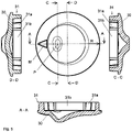
- the cover is in the Figures 2, 3 and 4 shown. 2 shows a perspective view of the cover element.
- 3 12 shows a plan view of the covering element of the first example, as well as a section AA arranged below the plan view, a section DD arranged to the left of the plan view and a section CC arranged to the right of the plan view.
- the courses of the sections A-A, D-D, C-C are drawn in the plan view.
- the section A-A is through the tip S of the guide surface and an undrawn center point, i. H. in the exit direction R
- the section D-D is through the midpoint and perpendicular to the exit direction R and the section C-C parallel to the section D-D offset towards the tip S.
- the cover element has a round plate 20 and means for fastening.
- the means for fastening have a collar 21 with latching elements 21a and collar elements 21b.
- the locking elements 21a alternate with collar elements 21b.
- the diameter of the collar 21 corresponds to the diameter of the opening 3b at the withdrawal end of the storage body 3.
- the latching elements 21a hold the cover element in the opening 3b.
- the plate 20 is shaped as a guide surface in this example.
- the guide surface is designed as an asymmetrical conical surface and has concavely curved surface sections.
- the elevation of the guide surface has a tip that is arranged asymmetrically in the area of the edge of the projection of the inlet opening of the inlet eyelet 13 onto the cover element.
- the tip is on the side of the holder 2a, ie at a position opposite to the exit direction R of the threading needle.
- the sections show the concave surface sections.
- the surface sections which, starting from the tip S, point towards the exit direction are concave.
- the plate 20 is provided with a marking M on the side opposite the exit direction R on its upper side.
- the M mark makes installation easier.
- the collar 21 is provided with a fitting element.
- the collar element 2b arranged below the marking M has a nose N protruding outwards.
- the opening 3b has a nose N corresponding recess.
- the plate 20 of the covering element has a diameter which is 20% to 80% of the diameter of the storage body 3 .
- the diameter of the plate 20 is approximately 60% of the diameter of the storage body 3.
- the elevation of the guide surface is 5% to 20% of the diameter of the storage body 3.
- the height is approximately 10% of the diameter of the storage body 3.
- the cover element is made of plastic by injection molding.
- the elevation of the guide surface of the plate is designed as a symmetrical cone, which is arranged offset against the exit direction.
- the tip of the cone is arranged asymmetrically in the area of the edge of the projection of the inlet opening onto the cover element.
- figure 5 shows a plan view of a cover member of a second example and sections AA, DD and CC, which correspond to those of FIG figure 3 correspond.
- a cover element of the second example is in figure 5 to see. It corresponds to that of the first example except for the following features:
- the cover element of the second example also has a round plate 30 and means for fastening.
- the attachment means have a collar 31 with latching elements 31a and collar elements 31b.
- the locking elements 31a alternate with the collar elements 31b.
- the plate 30 is shaped as a guide surface.
- the guide surface is designed as an asymmetrically oval conical surface with a flattened tip and has concavely curved surface sections.
- the collection of the guide surface has a highest area that formed by an oval plateau.
- the plateau is symmetrical and arranged asymmetrically in the area of the edge of the projection of the inlet opening of the inlet eyelet 13 onto the cover element.
- the plateau is located on the side of the holder 2a, ie at a point which is opposite to the exit direction R of the threading needle.
Landscapes
- Engineering & Computer Science (AREA)
- Textile Engineering (AREA)
- Knitting Machines (AREA)
- Sewing Machines And Sewing (AREA)
- Yarns And Mechanical Finishing Of Yarns Or Ropes (AREA)
Abstract
Description
- Die Erfindung betrifft ein Fadenliefergerät zur Lieferung eines Fadens zu einer Textilmaschine.
- Das Fadenliefergerät ist mit einem Speicherkörper versehen, von dem der Faden durch die Textilmaschine abgezogen wird. Ein derartiges Fadenliefergerät wird auch Speicher-Fadenliefergerät genannt. Das Fadenliefergerät weist eine im Fadenverlauf nach dem Speicherkörper angeordnete Bremsvorrichtung zur Einstellung einer Fadenspannung des Fadens auf. Die Bremsvorrichtung umfasst einen Bremskörper und eine Einstellvorrichtung für den Bremskörper.
- Ein solches Fadenliefergerät ist zum Beispiel in der
EP 3 296 242 B1 beschrieben. Der Bremskörper ist als ein nachgiebiger Bremskörperkonus in der Form eines regelmäßigen Kegelstumpfmantels ausgebildet. Nach einem Reißen des Fadens wird der Betrieb unterbrochen, um die Fadenenden wieder zu verknoten. Eines der Fadenenden wird durch die Einstellvorrichtung und den Bremskörper bis hin zum Speicherkörper oder umgekehrt vom Speicherkörper durch den Bremskörper und die Einstellvorrichtung eingefädelt. Dazu wird zum Beispiel eine flexible Einfädelnadel verwendet. - In der
DE 29 32 782 C2 ist eine Führungsbahn für eine Einfädelnadel beschrieben, die durch einen Führungsblock und eine Speiche gebildet wird. Die Einfädelnadel ist von der Zufuhrseite oder von der Abzugseite durchschiebbar. - Statt der Verwendung einer Einfädelnadel wird in der
EP 0 370 066 ein pneumatisches System eingesetzt. - Die
DE 100 54 103 beschreibt einen Einfädelkanal, der mechanisch mit einer Einfädelnadel oder pneumatisch genutzt werden kann. - Aufgabe der Erfindung ist es, ein Fadenliefergerät so zu verbessern, dass ein einfaches Einfädeln mit einer Einfädelnadel ermöglicht wird. Die Verbesserung soll einfach und platzsparend aufgebaut sein.
- Eine weitere Aufgabe ist es, eine Einfädelhilfe so auszubilden, dass die Austrittsrichtung, d. h. der radiale Austritt, der Einfädelnadel vorbestimmt werden kann.
- Die Aufgabe ist durch die Merkmale der Ansprüche gelöst.
- Ein erfindungsgemäßes Fadenliefergerät zur Lieferung eines Fadens zu einer Textilmaschine ist mit einem Gehäuse mit einem Halter, mit einem Speicherkörper, von dem der Faden durch die Textilmaschine abgezogen wird, und mit einer Bremsvorrichtung zur Einstellung einer Fadenspannung des Fadens versehen. Die Bremsvorrichtung ist im Fadenlauf nach dem Speicherkörper angeordnet. Die Bremsvorrichtung weist einen Bremskörper und eine Einstellvorrichtung für den Bremskörper auf. Der Bremskörper ist durch die Einstellvorrichtung gegen eine Klemmfläche am Abzugsende des Speicherkörpers anpressbar.
- In einer Ausführungsform ist der Bremskörper als ein Bremsring ausgebildet. In einer Ausführungsform ist der Bremsring mit elastischen Elementen versehen, die an die Klemmfläche anpressbar sind. In einer Ausführungsform ist der Bremskörper als ein Bremskonus ausgebildet. In einer Ausführungsform ist der Bremskörper aus elastischem Material hergestellt.
- In einer Ausführungsform ist der Bremskörper als ein nachgiebiger Bremskörperkonus in der Form eines regelmäßigen Kegelstumpfmantels ausgebildet, wobei der Bremskörper durch die Einstellvorrichtung im Bereich seines größeren Durchmessers gegen eine Klemmfläche am Abzugsende des Speicherkörpers angepresst ist, und im Bereich seines kleineren Durchmessers mit der Einstellvorrichtung verbunden ist.
- Die Einstellvorrichtung ist an dem Halter des Gehäuses angeordnet, der sich entlang des Speicherkörpers erstreckt. Die Einstellvorrichtung umfasst mindestens ein Stellelement und mindestens ein Auslaufelement.
- Das Stellelement ist zum Anpressen des Bremskörpers an die Klemmfläche bezüglich des Halters axial bewegbar ausgebildet.
- Das Auslaufelement ist mit einer zum Bremskörper ausgerichteten Einlauföffnung zur Führung des von dem Bremskörper kommenden Faden in Richtung der Textilmaschine versehen.
- Am Abzugsende des Speicherkörpers ist ein Abdeckelement vorgesehen. Das Abdeckelement ist mit einer Führungsfläche zum Führen einer von dem Auslaufelement kommenden Einfädelnadel ausgebildet. Die Führungsfläche weist eine Erhebung auf, deren Spitze asymmetrisch im Bereich des Randes der Projektion der Einlauföffnung auf das Abdeckelement angeordnet ist. Die Spitze der Erhebung befindet sich an einer Stelle, die einer Austrittsrichtung der Einfädelnadel entgegengesetzt ist. Die Austrittsrichtung ist vorbestimmt. Als Projektion der Einlauföffnung auf das Abdeckelement ist der kreisförmige Bereich auf dem Abdeckelement definiert, auf dem eine durch das Auslaufelement durch die Einlauföffnung geschobene Einfädelnadel trifft. Der kreisförmige Bereich ist bei gleichem Durchmesser der Einlauföffnung umso größer je weiter der Abstand der Einlauföffnung von dem Abdeckelement ist und je geringer die Höhe des, z. B. zylindrischen, Auslaufelementes ist.
- Die asymmetrische Anordnung der Spitze der Erhebung der Führungsfläche bezieht sich auf die Körperachse des Speicherkörpers. Das Auslaufelement ist im Wesentlichen konzentrisch zu der Körperachse ausgerichtet.
- In einer Ausführungsform ist die Austrittsrichtung auf der dem Halter des Gehäuses abgewandten Seite vorgesehen. Die Spitze der Erhebung der Führungsfläche befindet sich auf der Seite des Halters.
- Zum Verbinden zweier Fadenenden eines gerissenen Fadens wird eine Einfädelnadel durch das Auslaufelement geführt. Sie tritt aus der Einlauföffnung aus und trifft auf die Führungsfläche des Abdeckelementes. Die Einfädelnadel wird an der Führungsfläche in die Austrittsrichtung umgelenkt. In Austrittsrichtung wird sie zwischen dem Abzugsende des Speicherkörpers und dem Bremskörper hindurch nach außen geführt. Dort wird in die Einfädelnadel das Fadenende der auf dem Speicherkörper abgelegten Windungen eingelegt. Die Einfädelnadel wird mit dem mitgeführten Fadenende bis durch das Auslaufelement zurückgezogen. Außerhalb der Auslaufelemente werden die Fadenende miteinander verbunden.
- In einer Ausführungsform ist die Erhebung der Führungsfläche als ein Kegel ausgebildet. Der Kegel ist entgegen der Austrittsrichtung versetzt angeordnet.
- In einer Ausführungsform ist die Erhebung der Führungsfläche als eine asymmetrische kegelige Fläche ausgebildet. Die Führungsfläche weist ausgehend von der Spitze an einer Seite einen steileren Abfall und an der gegenüber liegenden Seite einen flacheren Abfall auf. Ausgehend von dem steileren Abfall mit einem entsprechend kleineren Radius ändert sich der Abfall auf dem Umfang der Führungsfläche kontinuierlich zu dem flacheren Abfall mit einem größeren Radius. Die Seite mit dem flacheren Abfall ist in Austrittsrichtung ausgerichtet. Die Ausbildung der Führungsfläche als eine asymmetrische kegelige Fläche hat den Vorteil, dass eine Spitze mit einer geringeren Höhe als bei einem symmetrischen Kegel benötigt wird.
- In einer Ausführungsform weist die Erhebung der Führungsfläche konkav gekrümmte Flächenabschnitte auf. Die konkave Form der Führungsfläche hat den Vorteil, dass der Abfall der Führungsfläche an ihrem Rand immer geringer und schließlich nahezu parallel zu einer Fläche in die Klemmfläche übergehenden Fläche verläuft. Die Führung der Einfädelnadel wird dadurch an dem Übergang von dem Abdeckelement zu dem Abzugsende des Speicherkörpers verbessert.
- In einer Ausführungsform weist die Führungsfläche des Abdeckelementes eine abgeflachte Spitze auf. D. h. die Führungsfläche weist einen höchsten Bereich auf, der z. B. durch ein Plateau gebildet ist. Das Plateau kann kreisförmig oder oval sein.
- In einer Ausführungsform kann die Spitze oder der höchste Bereich selbst asymmetrisch ausgebildet sein.
- In einer Ausführungsform ist die Platte mit einer Markierung versehen.
- In einer Ausführungsform ist das Abdeckelement als eine runde Platte ausgebildet, deren Durchmesser 20% bis 80% des Durchmessers des Speicherkörpers beträgt.
- In einer Ausführungsform beträgt die Höhe der Erhebung der Führungsfläche 5% bis 20% des Durchmessers des Speicherkörpers.
- In einer Ausführungsform weist das Abdeckelement Mittel zum Befestigen an dem Speicherkörper auf. In einer Ausführungsform weisen die Mittel zum Befestigen einen Kragen mit Rastelementen auf. In einer Ausführungsform weist der Kragen ein Passelement auf. Das Passelement legt die Einbaurichtung fest.
- In einer Ausführungsform ist das Abdeckelement aus Kunststoff oder Metall hergestellt.
- In einer Ausführungsform ist das Abdeckelement im Spritzgussverfahren oder im Tiefziehverfahren hergestellt.
- Ein erfindungsgemäßes Fadenliefergerät ist zur Lieferung eines Fadens zu einer Strickmaschine ausgebildet. Die Strickmaschine ist eine Rundstrickmaschine oder eine Flachstrickmaschine. Ein erfindungsgemäßes Fadenliefergerät ist alternativ zur Lieferung eines Schussfadens zu einer Webmaschine ausgebildet.
- Die Erfindung wird anhand von in der Zeichnung schematisch dargestellter Beispiele weiter erläutert. Es zeigen:
-
Fig. 1 eine schematische Darstellung anhand einer Seitenansicht eines erfindungsgemäßen Fadenliefergerätes, die im Bereich der Bremsvorrichtung als ein Schnitt parallel zur Achse des Speicherkörpers dargestellt ist und bei der der Weg der Spitze der Einfädelnadel entlang eines Abdeckelementes eines ersten Beispiels und der Verlauf des Fadens eingezeichnet sind; -
Fig. 2 eine perspektivische Darstellung des Abdeckelementes des ersten Beispiels; -
Fig. 3 eine Draufsicht auf das Abdeckelement des ersten Beispiels sowie einen Schnitt A-A, einen Schnitt D-D und Schnitt C-C; -
Fig. 4 eine Sicht von unten auf das Abdeckelement und ein Schnitt E-E, der zu dem Schnitt A-A um ca. 45° versetzt ist; -
Fig. 5 eine Draufsicht auf ein Abdeckelement eines zweiten Beispiels sowie Schnitte A-A, D-D und C-C, die denen derFigur 3 entsprechen. - Ein Fadenliefergerät 1 zur Lieferung eines Fadens 40 zu einer Textilmaschine, das in
Figur 1 dargestellt ist, ist als ein Speicher-Fadenliefergerät ausgebildet. - Das Fadenliefergerät 1 weist ein Gehäuse 2 und eine Speichervorrichtung mit einem Speicherkörper 3 auf, von dem ein Faden 40 durch die Textilmaschine abgezogen wird. Die Textilmaschine ist zum Beispiel eine Rundstrickmaschine.
- Das Gehäuse 2 umfasst einen Halter 2a und ein Antriebsgehäuse 2b. Der Halter 2a ist mit einer Befestigungsvorrichtung 4 zur Befestigung des Fadenliefergerätes 1 an der Textilmaschine, zum Beispiel an einem Maschinenring der Rundstrickmaschine, versehen.
- Das Fadenliefergerät 1 weist eine antreibbare Welle W auf, die in
Figur 1 im Bereich der Bremsvorrichtung zu sehen ist und auf der der Speicherkörper 3 über Lager L angeordnet ist. Die Welle W ist gegenüber dem Speicherkörper 3 drehbar gelagert. Der Speicherkörper 3 ist am Gehäuse 2 festgesetzt. Eine Körperachse K des Speicherkörpers 3, die im Wesentlichen der Achse der Welle W entspricht, ist inFigur 1 durch eine gestrichelte Linie gekennzeichnet. Ein in den Figuren nicht sichtbarer Antrieb der Welle W ist in dem Antriebsgehäuse 2b angeordnet. - Der Halter 2a des Gehäuses 2 erstreckt sich parallel zur Welle W entlang des Speicherkörpers 3.
- Der Speicherkörper 3 ist als eine Speichertrommel mit der Körperachse K ausgebildet, die parallel zur Achse der Welle W verläuft und, wie erwähnt, dieser im Wesentlichen entspricht. Der Speicherkörper 3 ist an seinem Abzugsende, d. h. in
Figur 1 unteren Ende abgerundet, um eine Klemmfläche 3a zu bilden. Er weist am Abzugsende eine Öffnung 3b auf. Durch die Öffnung 3b ist ein auf der Welle W angeordnetes Befestigungselement S zugänglich. Die Öffnung 3b ist in diesem Beispiel mit einem erhöhten Rand versehen. - Am Aufwickelende des Speicherkörpers 3, in
Figur 1 oben, ist ein Aufwickelelement 5 mit einem Fadenführungselement 5a zum Aufwickeln des Fadens 40 auf den Speicherkörper 3 der Speichervorrichtung angeordnet. Der an dieser Stelle inFigur 1 nicht eingezeichnete Faden 40 wird in Windungen, die als Faden- oder Garnwindungen bezeichnet werden, auf den Speicherkörper 3 aufgewickelt. - Die Speichervorrichtung umfasst neben dem Speicherkörper 3 einen Taumelkörper 6, der im Innern des Speicherkörpers 3 angeordnet ist.
- Die Bremsvorrichtung zur Einstellung einer Fadenspannung des Fadens 40 weist einen Bremskörper 8 und eine Einstellvorrichtung für den Bremskörper 8 auf. Die Bremsvorrichtung ist im Fadenlauf nach dem Speicherkörper 3 angeordnet, wobei der Bremskörper 8 am Abzugsende des Speicherkörpers 3 angeordnet ist.
- Der Bremskörper 8 ist konisch, und zwar als ein nachgiebiger Bremskörperkonus in der Form eines regelmäßigen Kegelstumpfmantels, ausgebildet. Er ist zum Beispiel aus einem Kunststoff und/oder Metall hergestellt. Entsprechende oder ähnliche Bremskörper sind zum Beispiel in der
WO 2006/045410 A1 beschrieben. - Die Achse des Bremskörpers 8 stimmt im Wesentlichen, d. h. bis auf geringe Abweichungen z. B. durch Abhebung durch den Faden 40 oder bei Verformung des elastischen Bremskörpers 8, mit der Körperachse K des Speicherkörpers 3 überein. Der Bremskörper 8 ragt mit seinem größeren Durchmesser über die Klemmfläche 3a. Er ist durch die Einstellvorrichtung gegen die Klemmfläche 3a am Abzugsende des Speicherkörpers 3 anpressbar.
- Beim Abzug des Fadens 40 durch die Textilmaschine läuft der Faden 40 vom Speicherkörper 3 zwischen dem Abzugsende des Speicherkörpers 3 und dem Bremskörper 8 über die Klemmfläche 3a.
- Die Einstellvorrichtung umfasst eine Stelleinheit mit mindestens einem Stellelement und eine Auslaufeinheit mit mindestens einem Auslaufelement.
- Die Stelleinheit weist eine Halterung des Bremskörpers 8 mit einem Innenring 10 und einem Außenring 11 auf, die an dem kleineren Durchmesser des Bremskörpers, d. h. an seinem von dem Speicherkörper 3 weg zeigenden Ende, angeordnet ist. Der Innenring 10 und der Außenring 11 sind durch Rastverbindungen miteinander verbunden.
- Die Auslaufeinheit umfasst einen Abzugszylinder 12, der an seinem zum Speicherkörper 3 zeigenden Ende mit einer Einlauföse 13 und an seinem entgegengesetzten Ende mit einer Auslauföse 14 versehen ist. Die Auslaufeinheit ragt mit der Einlauföse 13 in den Innenring 10 der Halterung des Bremskörpers 8. Der Abzugszylinder 12 erstreckt sich, ggf. bis auf Einbautoleranzen, parallel zur Achse K. Der Abzugszylinder 12 führt im Betrieb den Faden 40 von seinem dem Speicherkörper 3 zugewandten Einlaufende über die Einlauföse 13 zu seinem entgegengesetzten Auslaufende über die Auslauföse 14, d. h. durch die Einstellvorrichtung. Der Abzugszylinder 12 ist an dem Halter 2a des Gehäuses 2 angeordnet.
- In dem dargestellten Beispiel umfasst die Stelleinheit eine Permanentmagnetanordnung mit einem oberen Ring mit Permanentmagneten P1 und mit einem unteren Ring 15 mit Permanentmagneten P2. Der obere Ring ist als Außenring 11 der Halterung des Bremskörpers 8 ausgebildet. Der untere Ring 15 ist über eine Gewindeverbindung außen auf dem Abzugszylinder 12 angeordnet und durch manuelles Drehen axial bewegbar ausgebildet. Der Ring 15 bildet ein Stellelement, das zum Anpressen des Bremskörpers 8 an die Klemmfläche 3a bezüglich des Halters 2a axial bewegbar ausgebildet ist.
- Am Abzugsende des Speicherkörpers 3 ist ein Abdeckelement des ersten Beispiels vorgesehen.
-
Figur 1 zeigt den Weg N der Spitze einer Einfädelnadel, die an einer Stelle gegenüber des Halters 2a austritt. Eine Austrittsrichtung R zeigt im eingebauten Zustand des Abdeckelementes in Richtung von dem Halter 2a weg. Die Austrittsrichtung R ist in der Draufsicht derFigur 3 als Pfeil dargestellt. - Das Abdeckelement ist in den
Figuren 2, 3 und4 dargestellt.Fig. 2 zeigt eine perspektivische Darstellung des Abdeckelementes. -
Fig. 3 zeigt eine Draufsicht auf das Abdeckelement des ersten Beispiels sowie ein unterhalb der Draufsicht angeordneten Schnitt A-A, einen links neben der Draufsicht angeordneten Schnitt D-D und einen rechts neben der Draufsicht angeordneten Schnitt C-C. - Die Verläufe der Schnitte A-A, D-D, C-C sind in der Draufsicht eingezeichnet. Der Schnitt A-A ist durch die Spitze S der Führungsfläche und einen nicht eingezeichneten Mittelpunkt, d. h. in Austrittsrichtung R, der Schnitt D-D ist durch den Mittelpunkt und senkrecht zur Austrittsrichtung R und der Schnitt C-C parallel zum Schnitt D-D zur Spitze S hin versetzt gelegt.
-
Fig. 4 zeigt eine Sicht von unten auf das Abdeckelement und ein Schnitt E-E, der zum Schnitt A-A um ca. 45° versetzt ist. - Das Abdeckelement weist eine runde Platte 20 und Mittel zum Befestigen auf. Die Mittel zum Befestigen weisen einen Kragen 21 mit Rastelementen 21a und Kragenelementen 21b auf. Die Rastelemente 21a wechseln sich mit Kragenelementen 21b ab. Der Durchmesser des Kragens 21 entspricht dem Durchmesser der Öffnung 3b am Abzugsende des Speicherkörpers 3. Die Rastelemente 21a halten das Abdeckelement in der Öffnung 3b.
- Die Platte 20 ist in diesem Beispiel als eine Führungsfläche geformt. Die Führungsfläche ist als asymmetrische kegelige Fläche ausgebildet und weist konkav gekrümmte Flächenabschnitte auf.
- Die Erhebung der Führungsfläche weist eine Spitze auf, die asymmetrisch im Bereich des Randes der Projektion der Einlauföffnung der Einlauföse 13 auf das Abdeckelement angeordnet ist. Die Spitze befindet sich auf der Seite des Halters 2a, d. h. an einer Stelle, die der Austrittsrichtung R der Einfädelnadel entgegengesetzt ist.
- Die Schnitte zeigen die konkaven Flächenabschnitte. Die Flächenabschnitte, die ausgehend von der Spitze S zur Austrittsrichtung hinweisen, sind konkav ausgebildet.
- Die Platte 20 ist auf der der Austrittsrichtung R entgegengesetzten Seite auf ihrer Oberseite mit einer Markierung M versehen. Die Markierung M erleichtert den Einbau.
- Der Kragen 21 ist mit einem Passelement versehen. In diesem Beispiel weist das unterhalb der Markierung M angeordnete Kragenelement 2b eine nach außen ragende Nase N auf. Die Öffnung 3b weist eine der Nase N entsprechende Aussparung auf.
- Die Platte 20 des Abdeckelementes hat einen Durchmesser, der 20% bis 80% des Durchmessers des Speicherkörpers 3 beträgt. In diesem Beispiel beträgt der Durchmesser der Platte 20 in etwa 60% des Durchmessers des Speicherkörpers 3. Die Höhe der Erhebung der Führungsfläche beträgt 5% bis 20% des Durchmessers des Speicherkörpers 3. In diesem Beispiel beträgt die Höhe etwa 10% des Durchmessers des Speicherkörpers 3. Das Abdeckelement ist aus Kunststoff im Spritzgussverfahren hergestellt.
- Zum Verbinden von Fadenenden eines gerissenen Fadens 40 wird die Einfädelnadel durch die Auslauföse 14, den Abzugszylinder 12 und die Einlauföse 13 zu der die Führungsfläche bildende Platte 20 des Abdeckelementes geschoben und durch die Führungsfläche in Austrittsrichtung nach außen geführt. Dies ist in
Figur 2 skizziert. Die gepunktete Linie markiert den Verlauf des Faden 40 nach Verbinden der Fadenenden. - In einer Alternative ist die Erhebung der Führungsfläche der Platte als ein symmetrischer Kegel ausgebildet, der entgegen der Austrittsrichtung versetzt angeordnet ist. Die Spitze des Kegels ist asymmetrisch im Bereich des Randes der Projektion der Einlauföffnung auf das Abdeckelement angeordnet.
-
Figur 5 zeigt eine Draufsicht auf ein Abdeckelement eines zweiten Beispiels sowie Schnitte A-A, D-D und C-C, die denen derFigur 3 entsprechen. - Ein Abdeckelement des zweiten Beispiels ist in
Figur 5 zu sehen. Es entspricht dem des ersten Beispiels bis auf die folgenden Merkmale: Das Abdeckelement des zweiten Beispiels weist ebenfalls eine runde Platte 30 und Mittel zum Befestigen auf. Die Mittel zum Befestigen weisen einen Kragen 31 mit Rastelementen 31a und Kragenelementen 31b auf. Die Rastelemente 31a wechseln sich mit den Kragenelementen 31b ab. - Die Platte 30 ist als eine Führungsfläche geformt. Die Führungsfläche ist als asymmetrisch oval kegelige Fläche mit einer abgeflachten Spitze ausgebildet und weist konkav gekrümmte Flächenabschnitte auf. Die Erhebung der Führungsfläche weist einen höchsten Bereich auf, der durch ein ovales Plateau gebildet ist. Das Plateau ist symmetrisch ausgebildet und asymmetrisch im Bereich des Randes der Projektion der Einlauföffnung der Einlauföse 13 auf das Abdeckelement angeordnet. Das Plateau befindet sich auf der Seite des Halters 2a, d. h. an einer Stelle, die der Austrittsrichtung R der Einfädelnadel entgegengesetzt ist.
Bezugszeichenliste 1 Fadenliefergerät W Welle 2 Gehäuse L Lager 2a Halter S Befestigungselement 2b Antriebsgehäuse K Körperachse 3 Speicherkörper R Austrittsrichtung 3a Klemmfläche N Weg der Spitze der Einfädelnadel 3b Öffnung P1 Permanentmagnete 4 Befestigungsvorrichtung P2 Permanentmagnete 5 Aufwickelelement S Spitze 5a Fadenführungselement P Plateau 6 Taumelkörper M Markierung 8 Bremskörper N Nase 10 Innenring 11 Außenring 12 Abzugszylinder 13 Einlauföse 14 Auslauföse 15 Ring 20 Platte 21 Kragen 21a Rastelement 21b Kragenelement 30 Platte 31 Kragen 31a Rastelement 31b Kragenelement 40 Faden
Claims (10)
- Fadenliefergerät (1) zur Lieferung eines Fadens (40) zu einer Textilmaschine, mit einem Gehäuse (2) mit einem Halter (2a),mit einem Speicherkörper (3), von dem der Faden (40) durch die Textilmaschine abgezogen wird, mit einer Bremsvorrichtung zur Einstellung einer Fadenspannung des Fadens (40), die im Fadenlauf nach dem Speicherkörper (3) angeordnet ist, wobei die Bremsvorrichtung einen Bremskörper (8) und eine Einstellvorrichtung für den Bremskörper aufweist, wobei der Bremskörper (8) durch die Einstellvorrichtung gegen eine Klemmfläche (3a) am Abzugsende des Speicherkörpers (3) anpressbar ist, wobei die Einstellvorrichtung an dem Halter (2a) angeordnet ist, der sich entlang des Speicherkörpers (3) erstreckt, wobei die Einstellvorrichtung mindestens ein Stellelement und mindestens ein Auslaufelement umfasst, wobei das Stellelement zum Anpressen des Bremskörpers (8) an die Klemmfläche (3a) bezüglich des Halters (2a) axial bewegbar ausgebildet, und wobei das Auslaufelement mit einer zum Bremskörper ausgerichteten Einlauföffnung zur Führung des von dem Bremskörper (8) kommenden Faden (40) in Richtung der Textilmaschine versehen ist,dadurch gekennzeichnet, dassam Abzugsende des Speicherkörpers (3) ein Abdeckelement vorgesehen ist, wobei das Abdeckelement mit einer Führungsfläche zum Führen einer von dem Auslaufelement kommenden Einfädelnadel zum Bremskörper (8) versehen ist, wobei die Führungsfläche eine Erhebung aufweist, deren Spitze oder deren höchster Bereich asymmetrisch im Bereich des Randes der Projektion der Einlauföffnung auf das Abdeckelement angeordnet ist und sich an einer Stelle befindet, die einer Austrittsrichtung (R) der Einfädelnadel entgegengesetzt ist.
- Fadenliefergerät nach Anspruch 1, dadurch gekennzeichnet, dass die Erhebung der Führungsfläche als ein symmetrischer Kegel ausgebildet ist.
- Fadenliefergerät nach Anspruch 1 oder 2, dadurch gekennzeichnet, dass die Erhebung der Führungsfläche als eine asymmetrische kegelige Fläche ausgebildet ist.
- Fadenliefergerät nach einem der Ansprüche 1 bis 3, dadurch gekennzeichnet, dass die Erhebung der Führungsfläche konkav gekrümmte Flächenabschnitte aufweist.
- Fadenliefergerät nach einem der Ansprüche 1 bis 4, dadurch gekennzeichnet, dass das Abdeckelement als eine runde Platte (20, 30) ausgebildet ist, deren Durchmesser 20% bis 80% des Durchmessers des Speicherkörpers (3) beträgt.
- Fadenliefergerät nach einem der Ansprüche 1 bis 5, dadurch gekennzeichnet, dass die Höhe der Erhebung der Führungsfläche 5% bis 20% des Durchmessers des Speicherkörpers (3) beträgt.
- Fadenliefergerät nach einem der Ansprüche 1 bis 6, dadurch gekennzeichnet, dass das Abdeckelement Mittel zum Befestigen an dem Speicherkörper (3) aufweist.
- Fadenliefergerät nach Anspruch 7, dadurch gekennzeichnet, dass die Mittel zum Befestigen einen Kragen (21, 31) mit Rastelementen (21a, 31a) aufweisen.
- Fadenliefergerät nach einem der Ansprüche 1 bis 8, dadurch gekennzeichnet, dass das Abdeckelement aus Kunststoff oder aus Metall hergestellt ist.
- Fadenliefergerät nach einem der Ansprüche 1 bis 9, dadurch gekennzeichnet, dass das Abdeckelement im Spritzgussverfahren oder im Tiefziehverfahren hergestellt ist.
Applications Claiming Priority (1)
| Application Number | Priority Date | Filing Date | Title |
|---|---|---|---|
| DE102021115596.7A DE102021115596B3 (de) | 2021-06-16 | 2021-06-16 | Fadenliefergerät |
Publications (2)
| Publication Number | Publication Date |
|---|---|
| EP4105159A1 true EP4105159A1 (de) | 2022-12-21 |
| EP4105159B1 EP4105159B1 (de) | 2023-11-01 |
Family
ID=81256436
Family Applications (1)
| Application Number | Title | Priority Date | Filing Date |
|---|---|---|---|
| EP22172058.4A Active EP4105159B1 (de) | 2021-06-16 | 2022-05-06 | Fadenliefergerät |
Country Status (4)
| Country | Link |
|---|---|
| EP (1) | EP4105159B1 (de) |
| CN (1) | CN115478356B (de) |
| DE (1) | DE102021115596B3 (de) |
| TW (1) | TWI810939B (de) |
Citations (6)
| Publication number | Priority date | Publication date | Assignee | Title |
|---|---|---|---|---|
| DE2932782A1 (de) * | 1979-08-13 | 1981-03-26 | Aktiebolaget Iro, Ulricehamn | Fadenspeicher- und -liefervorrichtung fuer textilmaschinen |
| EP0370066A1 (de) | 1987-09-25 | 1990-05-30 | Iro Ab | Fadenspeicher- und liefervorrichtung. |
| DE10054103A1 (de) | 2000-10-31 | 2002-05-08 | Iro Patent Ag Baar | Fadenliefergerät |
| DE10107688A1 (de) * | 2001-02-19 | 2002-08-29 | Iro Patent Ag Baar | Fadenliefergerät |
| WO2006045410A1 (de) | 2004-10-21 | 2006-05-04 | Iro Ab | Faden-bremskörper |
| EP3296242B1 (de) | 2016-09-16 | 2021-03-10 | Memminger-IRO GmbH | Fadenliefergerät |
Family Cites Families (8)
| Publication number | Priority date | Publication date | Assignee | Title |
|---|---|---|---|---|
| CZ281873B6 (cs) | 1990-03-12 | 1997-03-12 | Iro Ab | Brzdný systém pro nanášecí válec příze s měnitelným účinkem |
| CN1045479C (zh) * | 1991-03-26 | 1999-10-06 | Iro有限公司 | 纱线制动装置 |
| DE19613055A1 (de) * | 1996-04-01 | 1997-10-02 | Iro Ab | Axiale Scheibenbremse und Fadenliefergerät mit axialer Scheibenbremse |
| DE19911943A1 (de) * | 1999-03-17 | 2000-09-21 | Iro Patent Ag Baar | Fadenliefergerät und Fadenbremskörper |
| DE102004039415A1 (de) * | 2004-08-13 | 2006-02-23 | Iro Ab | Fadenverarbeitendes System und Fadenliefergerät |
| DE102018115604A1 (de) * | 2018-06-28 | 2020-01-02 | Memminger-Iro Gmbh | Fadenliefergerät |
| DE102018115597A1 (de) * | 2018-06-28 | 2020-01-02 | Memminger-IRO Gesellschaft mit beschränkter Haftung | Fadenliefergerät und Verfahren zum Betreiben eines Fadenliefergerätes |
| IT201800007866A1 (it) * | 2018-08-06 | 2020-02-06 | Lgl Electronics Spa | Dispositivo frena-trama per alimentatori di filato ad accumulo |
-
2021
- 2021-06-16 DE DE102021115596.7A patent/DE102021115596B3/de not_active Expired - Fee Related
-
2022
- 2022-05-06 EP EP22172058.4A patent/EP4105159B1/de active Active
- 2022-05-19 TW TW111118652A patent/TWI810939B/zh active
- 2022-06-16 CN CN202210680584.6A patent/CN115478356B/zh active Active
Patent Citations (8)
| Publication number | Priority date | Publication date | Assignee | Title |
|---|---|---|---|---|
| DE2932782A1 (de) * | 1979-08-13 | 1981-03-26 | Aktiebolaget Iro, Ulricehamn | Fadenspeicher- und -liefervorrichtung fuer textilmaschinen |
| DE2932782C2 (de) | 1979-08-13 | 1985-08-22 | Aktiebolaget Iro, Ulricehamn | Fadenspeicher- und -liefervorrichtung für Textilmaschinen |
| EP0370066A1 (de) | 1987-09-25 | 1990-05-30 | Iro Ab | Fadenspeicher- und liefervorrichtung. |
| DE3876629T2 (de) * | 1987-09-25 | 1993-04-08 | Iro Ab | Fadenspeicher- und liefervorrichtung. |
| DE10054103A1 (de) | 2000-10-31 | 2002-05-08 | Iro Patent Ag Baar | Fadenliefergerät |
| DE10107688A1 (de) * | 2001-02-19 | 2002-08-29 | Iro Patent Ag Baar | Fadenliefergerät |
| WO2006045410A1 (de) | 2004-10-21 | 2006-05-04 | Iro Ab | Faden-bremskörper |
| EP3296242B1 (de) | 2016-09-16 | 2021-03-10 | Memminger-IRO GmbH | Fadenliefergerät |
Also Published As
| Publication number | Publication date |
|---|---|
| CN115478356A (zh) | 2022-12-16 |
| DE102021115596B3 (de) | 2022-05-12 |
| TW202311146A (zh) | 2023-03-16 |
| TWI810939B (zh) | 2023-08-01 |
| CN115478356B (zh) | 2025-06-27 |
| EP4105159B1 (de) | 2023-11-01 |
Similar Documents
| Publication | Publication Date | Title |
|---|---|---|
| EP2895646A1 (de) | Spinnstelle einer luftspinnmaschine | |
| EP1748094B1 (de) | Spinnvorrichtung zur Herstellung eines Fadens mittels eines umlaufenden Luftstroms | |
| EP2329067B1 (de) | Überwachungsverfahren und -vorrichtung zur verwendung in der herstellung von coregarn | |
| EP3587317A1 (de) | Fadenumlenkeinheit | |
| EP2758578B1 (de) | Fadenliefergerät zur zufuhr eines fadens zu einer textilmaschine | |
| EP0278053A1 (de) | Zungennadel für maschenbildende Textilmaschinen | |
| EP3850133B1 (de) | Webmaschine mit einer schussfadenfarbwahleinrichtung | |
| EP3296242B1 (de) | Fadenliefergerät | |
| DE102009023644A1 (de) | Fadenklemmeinrichtung für eine Spindel einer Spinn- oder Zwirnmaschine | |
| EP4105159B1 (de) | Fadenliefergerät | |
| CH662590A5 (de) | Fadenspanner fuer flachstrickmaschinen. | |
| DD222363A5 (de) | Fadenzufuhreinrichtung fuer strick- oder wirkmaschinen | |
| EP0527355A1 (de) | Verfahren und Vorrichtung zum pneumatischen Einführen von Faserband in eine Spinnereimaschine | |
| DE102018115604A1 (de) | Fadenliefergerät | |
| EP0223926B1 (de) | Verfahren und Vorrichtung zum Wiederanspinnen eines Fadens in einer Spinnvorrichtung | |
| EP2387954A1 (de) | Endoskopische Nähmaschine | |
| DE2932782C2 (de) | Fadenspeicher- und -liefervorrichtung für Textilmaschinen | |
| EP3577261B1 (de) | Kreiskamm mit kämmsegment und ausrichtsegment | |
| EP1052324B1 (de) | Nähmaschinennadel mit versetzten Öhrstegen | |
| DE3317267A1 (de) | Fadenzufuehrvorrichtung | |
| DE2330892A1 (de) | Schlingenfaengervorrichtung fuer naehmaschinen | |
| EP2886688A1 (de) | Einsatz und Spinnmaschine | |
| DE19718472A1 (de) | Flachstrickmaschine | |
| EP4474557A1 (de) | Fadenliefergerät zur zufuhr eines fadens zu einer textilmaschine | |
| DE102016106207A1 (de) | Saugkörper für eine pneumatisch arbeitende Faserverdichtungseinrichtung sowie damit ausgestattete Spinnereimaschine |
Legal Events
| Date | Code | Title | Description |
|---|---|---|---|
| PUAI | Public reference made under article 153(3) epc to a published international application that has entered the european phase |
Free format text: ORIGINAL CODE: 0009012 |
|
| STAA | Information on the status of an ep patent application or granted ep patent |
Free format text: STATUS: THE APPLICATION HAS BEEN PUBLISHED |
|
| AK | Designated contracting states |
Kind code of ref document: A1 Designated state(s): AL AT BE BG CH CY CZ DE DK EE ES FI FR GB GR HR HU IE IS IT LI LT LU LV MC MK MT NL NO PL PT RO RS SE SI SK SM TR |
|
| STAA | Information on the status of an ep patent application or granted ep patent |
Free format text: STATUS: REQUEST FOR EXAMINATION WAS MADE |
|
| 17P | Request for examination filed |
Effective date: 20230119 |
|
| RBV | Designated contracting states (corrected) |
Designated state(s): AL AT BE BG CH CY CZ DE DK EE ES FI FR GB GR HR HU IE IS IT LI LT LU LV MC MK MT NL NO PL PT RO RS SE SI SK SM TR |
|
| GRAP | Despatch of communication of intention to grant a patent |
Free format text: ORIGINAL CODE: EPIDOSNIGR1 |
|
| RIC1 | Information provided on ipc code assigned before grant |
Ipc: D04B 15/48 20060101ALI20230727BHEP Ipc: D03D 47/36 20060101ALI20230727BHEP Ipc: B65H 51/22 20060101AFI20230727BHEP |
|
| STAA | Information on the status of an ep patent application or granted ep patent |
Free format text: STATUS: GRANT OF PATENT IS INTENDED |
|
| GRAS | Grant fee paid |
Free format text: ORIGINAL CODE: EPIDOSNIGR3 |
|
| INTG | Intention to grant announced |
Effective date: 20230831 |
|
| GRAA | (expected) grant |
Free format text: ORIGINAL CODE: 0009210 |
|
| STAA | Information on the status of an ep patent application or granted ep patent |
Free format text: STATUS: THE PATENT HAS BEEN GRANTED |
|
| AK | Designated contracting states |
Kind code of ref document: B1 Designated state(s): AL AT BE BG CH CY CZ DE DK EE ES FI FR GB GR HR HU IE IS IT LI LT LU LV MC MK MT NL NO PL PT RO RS SE SI SK SM TR |
|
| REG | Reference to a national code |
Ref country code: GB Ref legal event code: FG4D Free format text: NOT ENGLISH |
|
| REG | Reference to a national code |
Ref country code: CH Ref legal event code: EP |
|
| REG | Reference to a national code |
Ref country code: IE Ref legal event code: FG4D Free format text: LANGUAGE OF EP DOCUMENT: GERMAN |
|
| REG | Reference to a national code |
Ref country code: DE Ref legal event code: R096 Ref document number: 502022000230 Country of ref document: DE |
|
| REG | Reference to a national code |
Ref country code: LT Ref legal event code: MG9D |
|
| REG | Reference to a national code |
Ref country code: NL Ref legal event code: MP Effective date: 20231101 Ref country code: DE Ref legal event code: R082 Ref document number: 502022000230 Country of ref document: DE Representative=s name: PAUL & ALBRECHT PATENTANWAELTE PARTG MBB, DE |
|
| PG25 | Lapsed in a contracting state [announced via postgrant information from national office to epo] |
Ref country code: GR Free format text: LAPSE BECAUSE OF FAILURE TO SUBMIT A TRANSLATION OF THE DESCRIPTION OR TO PAY THE FEE WITHIN THE PRESCRIBED TIME-LIMIT Effective date: 20240202 |
|
| PG25 | Lapsed in a contracting state [announced via postgrant information from national office to epo] |
Ref country code: IS Free format text: LAPSE BECAUSE OF FAILURE TO SUBMIT A TRANSLATION OF THE DESCRIPTION OR TO PAY THE FEE WITHIN THE PRESCRIBED TIME-LIMIT Effective date: 20240301 |
|
| PG25 | Lapsed in a contracting state [announced via postgrant information from national office to epo] |
Ref country code: LT Free format text: LAPSE BECAUSE OF FAILURE TO SUBMIT A TRANSLATION OF THE DESCRIPTION OR TO PAY THE FEE WITHIN THE PRESCRIBED TIME-LIMIT Effective date: 20231101 |
|
| PG25 | Lapsed in a contracting state [announced via postgrant information from national office to epo] |
Ref country code: NL Free format text: LAPSE BECAUSE OF FAILURE TO SUBMIT A TRANSLATION OF THE DESCRIPTION OR TO PAY THE FEE WITHIN THE PRESCRIBED TIME-LIMIT Effective date: 20231101 |
|
| PG25 | Lapsed in a contracting state [announced via postgrant information from national office to epo] |
Ref country code: ES Free format text: LAPSE BECAUSE OF FAILURE TO SUBMIT A TRANSLATION OF THE DESCRIPTION OR TO PAY THE FEE WITHIN THE PRESCRIBED TIME-LIMIT Effective date: 20231101 |
|
| PG25 | Lapsed in a contracting state [announced via postgrant information from national office to epo] |
Ref country code: NL Free format text: LAPSE BECAUSE OF FAILURE TO SUBMIT A TRANSLATION OF THE DESCRIPTION OR TO PAY THE FEE WITHIN THE PRESCRIBED TIME-LIMIT Effective date: 20231101 Ref country code: LT Free format text: LAPSE BECAUSE OF FAILURE TO SUBMIT A TRANSLATION OF THE DESCRIPTION OR TO PAY THE FEE WITHIN THE PRESCRIBED TIME-LIMIT Effective date: 20231101 Ref country code: IS Free format text: LAPSE BECAUSE OF FAILURE TO SUBMIT A TRANSLATION OF THE DESCRIPTION OR TO PAY THE FEE WITHIN THE PRESCRIBED TIME-LIMIT Effective date: 20240301 Ref country code: GR Free format text: LAPSE BECAUSE OF FAILURE TO SUBMIT A TRANSLATION OF THE DESCRIPTION OR TO PAY THE FEE WITHIN THE PRESCRIBED TIME-LIMIT Effective date: 20240202 Ref country code: ES Free format text: LAPSE BECAUSE OF FAILURE TO SUBMIT A TRANSLATION OF THE DESCRIPTION OR TO PAY THE FEE WITHIN THE PRESCRIBED TIME-LIMIT Effective date: 20231101 Ref country code: BG Free format text: LAPSE BECAUSE OF FAILURE TO SUBMIT A TRANSLATION OF THE DESCRIPTION OR TO PAY THE FEE WITHIN THE PRESCRIBED TIME-LIMIT Effective date: 20240201 Ref country code: PT Free format text: LAPSE BECAUSE OF FAILURE TO SUBMIT A TRANSLATION OF THE DESCRIPTION OR TO PAY THE FEE WITHIN THE PRESCRIBED TIME-LIMIT Effective date: 20240301 |
|
| PG25 | Lapsed in a contracting state [announced via postgrant information from national office to epo] |
Ref country code: SE Free format text: LAPSE BECAUSE OF FAILURE TO SUBMIT A TRANSLATION OF THE DESCRIPTION OR TO PAY THE FEE WITHIN THE PRESCRIBED TIME-LIMIT Effective date: 20231101 Ref country code: RS Free format text: LAPSE BECAUSE OF FAILURE TO SUBMIT A TRANSLATION OF THE DESCRIPTION OR TO PAY THE FEE WITHIN THE PRESCRIBED TIME-LIMIT Effective date: 20231101 Ref country code: PL Free format text: LAPSE BECAUSE OF FAILURE TO SUBMIT A TRANSLATION OF THE DESCRIPTION OR TO PAY THE FEE WITHIN THE PRESCRIBED TIME-LIMIT Effective date: 20231101 Ref country code: NO Free format text: LAPSE BECAUSE OF FAILURE TO SUBMIT A TRANSLATION OF THE DESCRIPTION OR TO PAY THE FEE WITHIN THE PRESCRIBED TIME-LIMIT Effective date: 20240201 Ref country code: LV Free format text: LAPSE BECAUSE OF FAILURE TO SUBMIT A TRANSLATION OF THE DESCRIPTION OR TO PAY THE FEE WITHIN THE PRESCRIBED TIME-LIMIT Effective date: 20231101 Ref country code: HR Free format text: LAPSE BECAUSE OF FAILURE TO SUBMIT A TRANSLATION OF THE DESCRIPTION OR TO PAY THE FEE WITHIN THE PRESCRIBED TIME-LIMIT Effective date: 20231101 |
|
| P01 | Opt-out of the competence of the unified patent court (upc) registered |
Effective date: 20240507 |
|
| PG25 | Lapsed in a contracting state [announced via postgrant information from national office to epo] |
Ref country code: DK Free format text: LAPSE BECAUSE OF FAILURE TO SUBMIT A TRANSLATION OF THE DESCRIPTION OR TO PAY THE FEE WITHIN THE PRESCRIBED TIME-LIMIT Effective date: 20231101 |
|
| PG25 | Lapsed in a contracting state [announced via postgrant information from national office to epo] |
Ref country code: CZ Free format text: LAPSE BECAUSE OF FAILURE TO SUBMIT A TRANSLATION OF THE DESCRIPTION OR TO PAY THE FEE WITHIN THE PRESCRIBED TIME-LIMIT Effective date: 20231101 |
|
| PG25 | Lapsed in a contracting state [announced via postgrant information from national office to epo] |
Ref country code: SK Free format text: LAPSE BECAUSE OF FAILURE TO SUBMIT A TRANSLATION OF THE DESCRIPTION OR TO PAY THE FEE WITHIN THE PRESCRIBED TIME-LIMIT Effective date: 20231101 |
|
| PG25 | Lapsed in a contracting state [announced via postgrant information from national office to epo] |
Ref country code: SM Free format text: LAPSE BECAUSE OF FAILURE TO SUBMIT A TRANSLATION OF THE DESCRIPTION OR TO PAY THE FEE WITHIN THE PRESCRIBED TIME-LIMIT Effective date: 20231101 Ref country code: SK Free format text: LAPSE BECAUSE OF FAILURE TO SUBMIT A TRANSLATION OF THE DESCRIPTION OR TO PAY THE FEE WITHIN THE PRESCRIBED TIME-LIMIT Effective date: 20231101 Ref country code: EE Free format text: LAPSE BECAUSE OF FAILURE TO SUBMIT A TRANSLATION OF THE DESCRIPTION OR TO PAY THE FEE WITHIN THE PRESCRIBED TIME-LIMIT Effective date: 20231101 Ref country code: DK Free format text: LAPSE BECAUSE OF FAILURE TO SUBMIT A TRANSLATION OF THE DESCRIPTION OR TO PAY THE FEE WITHIN THE PRESCRIBED TIME-LIMIT Effective date: 20231101 Ref country code: CZ Free format text: LAPSE BECAUSE OF FAILURE TO SUBMIT A TRANSLATION OF THE DESCRIPTION OR TO PAY THE FEE WITHIN THE PRESCRIBED TIME-LIMIT Effective date: 20231101 |
|
| REG | Reference to a national code |
Ref country code: DE Ref legal event code: R097 Ref document number: 502022000230 Country of ref document: DE |
|
| PLBE | No opposition filed within time limit |
Free format text: ORIGINAL CODE: 0009261 |
|
| STAA | Information on the status of an ep patent application or granted ep patent |
Free format text: STATUS: NO OPPOSITION FILED WITHIN TIME LIMIT |
|
| 26N | No opposition filed |
Effective date: 20240802 |
|
| PG25 | Lapsed in a contracting state [announced via postgrant information from national office to epo] |
Ref country code: SI Free format text: LAPSE BECAUSE OF FAILURE TO SUBMIT A TRANSLATION OF THE DESCRIPTION OR TO PAY THE FEE WITHIN THE PRESCRIBED TIME-LIMIT Effective date: 20231101 |
|
| PG25 | Lapsed in a contracting state [announced via postgrant information from national office to epo] |
Ref country code: SI Free format text: LAPSE BECAUSE OF FAILURE TO SUBMIT A TRANSLATION OF THE DESCRIPTION OR TO PAY THE FEE WITHIN THE PRESCRIBED TIME-LIMIT Effective date: 20231101 |
|
| PG25 | Lapsed in a contracting state [announced via postgrant information from national office to epo] |
Ref country code: MC Free format text: LAPSE BECAUSE OF FAILURE TO SUBMIT A TRANSLATION OF THE DESCRIPTION OR TO PAY THE FEE WITHIN THE PRESCRIBED TIME-LIMIT Effective date: 20231101 |
|
| PG25 | Lapsed in a contracting state [announced via postgrant information from national office to epo] |
Ref country code: LU Free format text: LAPSE BECAUSE OF NON-PAYMENT OF DUE FEES Effective date: 20240506 |
|
| PG25 | Lapsed in a contracting state [announced via postgrant information from national office to epo] |
Ref country code: MC Free format text: LAPSE BECAUSE OF FAILURE TO SUBMIT A TRANSLATION OF THE DESCRIPTION OR TO PAY THE FEE WITHIN THE PRESCRIBED TIME-LIMIT Effective date: 20231101 Ref country code: LU Free format text: LAPSE BECAUSE OF NON-PAYMENT OF DUE FEES Effective date: 20240506 |
|
| REG | Reference to a national code |
Ref country code: BE Ref legal event code: MM Effective date: 20240531 |
|
| PG25 | Lapsed in a contracting state [announced via postgrant information from national office to epo] |
Ref country code: IE Free format text: LAPSE BECAUSE OF NON-PAYMENT OF DUE FEES Effective date: 20240506 |
|
| PG25 | Lapsed in a contracting state [announced via postgrant information from national office to epo] |
Ref country code: BE Free format text: LAPSE BECAUSE OF NON-PAYMENT OF DUE FEES Effective date: 20240531 |
|
| PG25 | Lapsed in a contracting state [announced via postgrant information from national office to epo] |
Ref country code: FR Free format text: LAPSE BECAUSE OF NON-PAYMENT OF DUE FEES Effective date: 20240531 |
|
| PGFP | Annual fee paid to national office [announced via postgrant information from national office to epo] |
Ref country code: DE Payment date: 20250519 Year of fee payment: 4 |
|
| PGFP | Annual fee paid to national office [announced via postgrant information from national office to epo] |
Ref country code: IT Payment date: 20250531 Year of fee payment: 4 |
|
| PGFP | Annual fee paid to national office [announced via postgrant information from national office to epo] |
Ref country code: AT Payment date: 20250721 Year of fee payment: 4 |
|
| PGFP | Annual fee paid to national office [announced via postgrant information from national office to epo] |
Ref country code: TR Payment date: 20250429 Year of fee payment: 4 |
|
| PG25 | Lapsed in a contracting state [announced via postgrant information from national office to epo] |
Ref country code: RO Free format text: LAPSE BECAUSE OF FAILURE TO SUBMIT A TRANSLATION OF THE DESCRIPTION OR TO PAY THE FEE WITHIN THE PRESCRIBED TIME-LIMIT Effective date: 20231101 |
|
| PG25 | Lapsed in a contracting state [announced via postgrant information from national office to epo] |
Ref country code: CY Free format text: LAPSE BECAUSE OF FAILURE TO SUBMIT A TRANSLATION OF THE DESCRIPTION OR TO PAY THE FEE WITHIN THE PRESCRIBED TIME-LIMIT; INVALID AB INITIO Effective date: 20220506 |
|
| PG25 | Lapsed in a contracting state [announced via postgrant information from national office to epo] |
Ref country code: HU Free format text: LAPSE BECAUSE OF FAILURE TO SUBMIT A TRANSLATION OF THE DESCRIPTION OR TO PAY THE FEE WITHIN THE PRESCRIBED TIME-LIMIT; INVALID AB INITIO Effective date: 20220506 |
|
| PG25 | Lapsed in a contracting state [announced via postgrant information from national office to epo] |
Ref country code: FI Free format text: LAPSE BECAUSE OF FAILURE TO SUBMIT A TRANSLATION OF THE DESCRIPTION OR TO PAY THE FEE WITHIN THE PRESCRIBED TIME-LIMIT Effective date: 20231101 |
|
| REG | Reference to a national code |
Ref country code: CH Ref legal event code: H13 Free format text: ST27 STATUS EVENT CODE: U-0-0-H10-H13 (AS PROVIDED BY THE NATIONAL OFFICE) Effective date: 20251223 |
|
| PG25 | Lapsed in a contracting state [announced via postgrant information from national office to epo] |
Ref country code: CH Free format text: LAPSE BECAUSE OF NON-PAYMENT OF DUE FEES Effective date: 20250531 |