EP4105006B1 - Vorrichtung zur pressenden bearbeitung von flachmaterial - Google Patents
Vorrichtung zur pressenden bearbeitung von flachmaterial Download PDFInfo
- Publication number
- EP4105006B1 EP4105006B1 EP22177899.6A EP22177899A EP4105006B1 EP 4105006 B1 EP4105006 B1 EP 4105006B1 EP 22177899 A EP22177899 A EP 22177899A EP 4105006 B1 EP4105006 B1 EP 4105006B1
- Authority
- EP
- European Patent Office
- Prior art keywords
- flat material
- press
- pressing
- heating
- heating means
- Prior art date
- Legal status (The legal status is an assumption and is not a legal conclusion. Google has not performed a legal analysis and makes no representation as to the accuracy of the status listed.)
- Active
Links
Images


Classifications
-
- B—PERFORMING OPERATIONS; TRANSPORTING
- B29—WORKING OF PLASTICS; WORKING OF SUBSTANCES IN A PLASTIC STATE IN GENERAL
- B29C—SHAPING OR JOINING OF PLASTICS; SHAPING OF MATERIAL IN A PLASTIC STATE, NOT OTHERWISE PROVIDED FOR; AFTER-TREATMENT OF THE SHAPED PRODUCTS, e.g. REPAIRING
- B29C70/00—Shaping composites, i.e. plastics material comprising reinforcements, fillers or preformed parts, e.g. inserts
- B29C70/04—Shaping composites, i.e. plastics material comprising reinforcements, fillers or preformed parts, e.g. inserts comprising reinforcements only, e.g. self-reinforcing plastics
- B29C70/28—Shaping operations therefor
- B29C70/40—Shaping or impregnating by compression not applied
- B29C70/50—Shaping or impregnating by compression not applied for producing articles of indefinite length, e.g. prepregs, sheet moulding compounds [SMC] or cross moulding compounds [XMC]
- B29C70/504—Shaping or impregnating by compression not applied for producing articles of indefinite length, e.g. prepregs, sheet moulding compounds [SMC] or cross moulding compounds [XMC] using rollers or pressure bands
-
- B—PERFORMING OPERATIONS; TRANSPORTING
- B27—WORKING OR PRESERVING WOOD OR SIMILAR MATERIAL; NAILING OR STAPLING MACHINES IN GENERAL
- B27N—MANUFACTURE BY DRY PROCESSES OF ARTICLES, WITH OR WITHOUT ORGANIC BINDING AGENTS, MADE FROM PARTICLES OR FIBRES CONSISTING OF WOOD OR OTHER LIGNOCELLULOSIC OR LIKE ORGANIC MATERIAL
- B27N3/00—Manufacture of substantially flat articles, e.g. boards, from particles or fibres
- B27N3/08—Moulding or pressing
- B27N3/24—Moulding or pressing characterised by using continuously acting presses having endless belts or chains moved within the compression zone
-
- B—PERFORMING OPERATIONS; TRANSPORTING
- B29—WORKING OF PLASTICS; WORKING OF SUBSTANCES IN A PLASTIC STATE IN GENERAL
- B29C—SHAPING OR JOINING OF PLASTICS; SHAPING OF MATERIAL IN A PLASTIC STATE, NOT OTHERWISE PROVIDED FOR; AFTER-TREATMENT OF THE SHAPED PRODUCTS, e.g. REPAIRING
- B29C43/00—Compression moulding, i.e. applying external pressure to flow the moulding material; Apparatus therefor
- B29C43/22—Compression moulding, i.e. applying external pressure to flow the moulding material; Apparatus therefor of articles of indefinite length
- B29C43/24—Calendering
- B29C43/245—Adjusting calender parameters, e.g. bank quantity
-
- B—PERFORMING OPERATIONS; TRANSPORTING
- B29—WORKING OF PLASTICS; WORKING OF SUBSTANCES IN A PLASTIC STATE IN GENERAL
- B29C—SHAPING OR JOINING OF PLASTICS; SHAPING OF MATERIAL IN A PLASTIC STATE, NOT OTHERWISE PROVIDED FOR; AFTER-TREATMENT OF THE SHAPED PRODUCTS, e.g. REPAIRING
- B29C43/00—Compression moulding, i.e. applying external pressure to flow the moulding material; Apparatus therefor
- B29C43/32—Component parts, details or accessories; Auxiliary operations
- B29C43/44—Compression means for making articles of indefinite length
- B29C43/46—Rollers
-
- B—PERFORMING OPERATIONS; TRANSPORTING
- B29—WORKING OF PLASTICS; WORKING OF SUBSTANCES IN A PLASTIC STATE IN GENERAL
- B29C—SHAPING OR JOINING OF PLASTICS; SHAPING OF MATERIAL IN A PLASTIC STATE, NOT OTHERWISE PROVIDED FOR; AFTER-TREATMENT OF THE SHAPED PRODUCTS, e.g. REPAIRING
- B29C43/00—Compression moulding, i.e. applying external pressure to flow the moulding material; Apparatus therefor
- B29C43/32—Component parts, details or accessories; Auxiliary operations
- B29C43/52—Heating or cooling
-
- B—PERFORMING OPERATIONS; TRANSPORTING
- B29—WORKING OF PLASTICS; WORKING OF SUBSTANCES IN A PLASTIC STATE IN GENERAL
- B29C—SHAPING OR JOINING OF PLASTICS; SHAPING OF MATERIAL IN A PLASTIC STATE, NOT OTHERWISE PROVIDED FOR; AFTER-TREATMENT OF THE SHAPED PRODUCTS, e.g. REPAIRING
- B29C43/00—Compression moulding, i.e. applying external pressure to flow the moulding material; Apparatus therefor
- B29C43/32—Component parts, details or accessories; Auxiliary operations
- B29C43/58—Measuring, controlling or regulating
-
- B—PERFORMING OPERATIONS; TRANSPORTING
- B29—WORKING OF PLASTICS; WORKING OF SUBSTANCES IN A PLASTIC STATE IN GENERAL
- B29C—SHAPING OR JOINING OF PLASTICS; SHAPING OF MATERIAL IN A PLASTIC STATE, NOT OTHERWISE PROVIDED FOR; AFTER-TREATMENT OF THE SHAPED PRODUCTS, e.g. REPAIRING
- B29C70/00—Shaping composites, i.e. plastics material comprising reinforcements, fillers or preformed parts, e.g. inserts
- B29C70/04—Shaping composites, i.e. plastics material comprising reinforcements, fillers or preformed parts, e.g. inserts comprising reinforcements only, e.g. self-reinforcing plastics
- B29C70/28—Shaping operations therefor
- B29C70/54—Component parts, details or accessories; Auxiliary operations, e.g. feeding or storage of prepregs or SMC after impregnation or during ageing
-
- B—PERFORMING OPERATIONS; TRANSPORTING
- B30—PRESSES
- B30B—PRESSES IN GENERAL
- B30B15/00—Details of, or accessories for, presses; Auxiliary measures in connection with pressing
- B30B15/34—Heating or cooling presses or parts thereof
-
- B—PERFORMING OPERATIONS; TRANSPORTING
- B30—PRESSES
- B30B—PRESSES IN GENERAL
- B30B3/00—Presses characterised by the use of rotary pressing members, e.g. rollers, rings, discs
- B30B3/04—Presses characterised by the use of rotary pressing members, e.g. rollers, rings, discs co-operating with one another, e.g. with co-operating cones
-
- B—PERFORMING OPERATIONS; TRANSPORTING
- B30—PRESSES
- B30B—PRESSES IN GENERAL
- B30B5/00—Presses characterised by the use of pressing means other than those mentioned in the preceding groups
- B30B5/04—Presses characterised by the use of pressing means other than those mentioned in the preceding groups wherein the pressing means is in the form of an endless band
- B30B5/06—Presses characterised by the use of pressing means other than those mentioned in the preceding groups wherein the pressing means is in the form of an endless band co-operating with another endless band
-
- H—ELECTRICITY
- H05—ELECTRIC TECHNIQUES NOT OTHERWISE PROVIDED FOR
- H05B—ELECTRIC HEATING; ELECTRIC LIGHT SOURCES NOT OTHERWISE PROVIDED FOR; CIRCUIT ARRANGEMENTS FOR ELECTRIC LIGHT SOURCES, IN GENERAL
- H05B6/00—Heating by electric, magnetic or electromagnetic fields
- H05B6/02—Induction heating
-
- B—PERFORMING OPERATIONS; TRANSPORTING
- B29—WORKING OF PLASTICS; WORKING OF SUBSTANCES IN A PLASTIC STATE IN GENERAL
- B29C—SHAPING OR JOINING OF PLASTICS; SHAPING OF MATERIAL IN A PLASTIC STATE, NOT OTHERWISE PROVIDED FOR; AFTER-TREATMENT OF THE SHAPED PRODUCTS, e.g. REPAIRING
- B29C43/00—Compression moulding, i.e. applying external pressure to flow the moulding material; Apparatus therefor
- B29C43/32—Component parts, details or accessories; Auxiliary operations
- B29C43/44—Compression means for making articles of indefinite length
- B29C43/46—Rollers
- B29C2043/461—Rollers the rollers having specific surface features
-
- B—PERFORMING OPERATIONS; TRANSPORTING
- B29—WORKING OF PLASTICS; WORKING OF SUBSTANCES IN A PLASTIC STATE IN GENERAL
- B29C—SHAPING OR JOINING OF PLASTICS; SHAPING OF MATERIAL IN A PLASTIC STATE, NOT OTHERWISE PROVIDED FOR; AFTER-TREATMENT OF THE SHAPED PRODUCTS, e.g. REPAIRING
- B29C43/00—Compression moulding, i.e. applying external pressure to flow the moulding material; Apparatus therefor
- B29C43/32—Component parts, details or accessories; Auxiliary operations
- B29C43/58—Measuring, controlling or regulating
- B29C2043/5808—Measuring, controlling or regulating pressure or compressing force
Definitions
- the invention relates to a device for the pressing processing of flat material according to the preamble of claim 1.
- Such devices can be used, for example, for pressing processes, particularly for the continuous lamination and/or impregnation of flat material webs or material segments. Heating elements can also be provided to heat the flat material for pressing.
- the device can be, for example, a double-belt press, which is used, for example, for the production of fiber-reinforced plastics.
- a device of the type mentioned above is known from EP 2 540 475 B1
- This is a double belt press in which two endless steel belts are driven and pressed against each other with their respective working strands, with the material to be processed being guided and pressed between the steel belts in the direction of transport.
- the steel belts and thus indirectly the flat material to be pressed are heated for processing using inductive heating elements.
- the flat material is a composite material made of thermoplastic and filaments.
- a cooling unit comprising press rollers is provided behind the heating elements in the direction of transport, which presses the top and bottom of the flat material via the steel belts. Cooling water flows through at least one of the press rollers for cooling purposes.
- the inductive heating elements each surround the two steel belts in the heating area.
- the heating elements are designed in such a way that they have a lower half and an upper half that can be temporarily separated from one another at connection points, thus allowing an opening movement of the working strand of at least one of the steel belts.
- the press rollers create a line contact with the steel strip and thus a pressure application that is strictly limited in time and location.
- a device for applying a surface pressure to advancing workpieces which also represents a double belt press. Pressing pressure is generated by pressure plates arranged on both sides of the respective working strand of the press belts.
- the transport of the flat material is made possible by closed paths of roller strands that are guided between the respective pressure plate and the associated press belt, roll on the pressure plates and transport the press belt and the workpiece clamped between the press belts. It is proposed that the rollers on each roller strand be positively and/or non-positively connected to one another, enclose an axle rod with an annular gap that exceeds the bearing play, and are elastically deformable up to the axle contact on the axle rod.
- the elastic deformability of the rollers can have a tolerance-compensating effect.
- the aforementioned annular gap can have a heat-insulating effect to protect the axle rod if the pressure plates are heated or cooled. How active heating could be achieved is not shown in this prior art.
- a double-belt press in which a plurality of press roller pairs are provided, the gap spacing between which allows the passage of the flat material being adjustable.
- the gap spacing is regulated by a pressure, which is controlled by a pressure measuring device in a calibration section of the double-belt press.
- the steel belt can be heated by means of sliding shoes that slide on the respective steel belt and are arranged between each pair of press rollers. The sliding shoes cause abrasion and thus increase the wear of the double-belt press.
- the EP3 061 859 A1 discloses a device for producing films using waste paper fibers, in which thin, web-like flat material is first formed on a mesh belt and then fed to pressing processes via a conveyor belt. Pressing is performed by pairs of press rollers, with an initial pressing process without heating the flat material, followed by a further pressing process at lower pressure and simultaneous heating. Both pressing processes act directly on the flat material. A double-belt press is therefore not implemented.
- the flat material can be heated using halogen heaters provided in the heating press rollers.
- press rollers with an elastic layer, e.g., made of plastic.
- the elastic properties of the press rollers are intended to ensure contact between the press rollers over their entire axial length.
- a device for producing composite material components in which a rolling, roller-shaped pressure unit with an elastically flexible pressure pad presses onto the strip-shaped workpiece lying on a solid base, the latter being heated with laser radiation immediately before pressing.
- a pair of press rollers with counter-operating press rollers is not disclosed.
- Special measures are provided to protect the pressure pad from overheating due to incident laser radiation, such as a pressure pad material that is (partially) transparent to laser radiation, shading the pressure pad from the laser radiation, or a cooling fluid passed through the pressure pad.
- the elastically flexible pressure pad serves here to compensate for height differences on three-dimensional workpiece surfaces when applying strip material.
- the invention is based on the technical problem of providing a device of the type mentioned at the outset which enables a more favorable pressure distribution of the press rollers acting on the flat material.
- a device according to the preamble of claim 1 is characterized in that both press rollers of the press roller pair or at least one of the press roller pairs have, at least on their circumference in the radial direction, an increased elastic deformability compared to steel press rollers.
- the elastic deformability distributes the pressing force over a larger area.
- This surface pressure results in a longer pressure application time compared to the linear contact pressures of conventional steel rollers or steel press rollers, thus resulting in an improved and more homogeneous pressing effect.
- the device according to the invention can advantageously be designed such that at least two pairs of press rollers are arranged one behind the other in the transport direction.
- the device according to the invention is particularly advantageous because it is designed as a double belt press.
- the at least one pair of press rollers acts indirectly, namely via one of the belts on the flat material.
- the elastic deformability of the rollers of the at least one pair of press rollers is gentle on the belts used, without losing the advantage of surface pressure compared to pure line contact.
- the belt pair and the at least one pair of press rollers form the means for transporting the flat material to be processed.
- the device according to the invention has at least one heating element for heating the flat material.
- Heating elements are typically used for the production of composite materials or for lamination.
- One or more heating elements may be useful for the invention. Even if, for linguistic simplicity, the heating elements are usually referred to in the plural in the following description of the invention. the invention also relates to corresponding embodiments with only one heating element.
- the heating elements can act on the flat material indirectly via the belts of the double-belt press.
- inductive heating is used.
- One or more inductors are preferably arranged on both sides of the working areas of the press belts.
- the device according to the invention can also be designed such that at least a portion of the heating means is configured to generate magnetic fields having a predominantly magnetic field component oriented perpendicular to a center plane of the flat material.
- This can be achieved by means of a flat inductor or a similarly constructed inductor with a corresponding effect.
- the heating means or at least a portion of the heating means have a meandering course, at least in sections.
- the meandering course can be aligned such that the loops of the meander, during use, run parallel to the center plane of the flat material to be heated.
- the heating means are designed to surround a portion of the flat material to be heated in a U-shape.
- the inductors can be configured such that they can be pushed into a working position along a longitudinal side of the flat material. This does not completely enclose the flat material, which is why a relative movement of two parts of the same inductor to each other, associated with the opening and closing of electrical contacts, is not required.
- the effect of the heating element on the material to be heated can depend significantly on the distance from the material, particularly for an inductive heater with its interaction with the inductively coupled material.
- the latter can be the flat material to be processed.
- the induction currents are usually generated in the belt material of the double-belt press, which in turn conductively heats the flat material to be processed.
- the elastic deformability of the press rollers of at least one pair of press rollers can lead to a shift in the position of a center plane of the flat material running parallel to the transport direction and parallel to the axes of rotation of the press rollers, perpendicular to this center plane. This shift can occur, for example, if, during pressure buildup, the position of the axis of rotation of one of the press rollers of a pair of press rollers in the device remains constant, while the axis of rotation of the other press roller shifts.
- the device according to the invention in such a way that means are provided which enable the position of the at least one heating element to be adapted to the position of the central plane.
- Such adjustment can be achieved by passively tracking the at least one heating element, for example, by means of spacers between the flat material or the associated belt of the double-belt press and the at least one heating element.
- spacer can be achieved, for example, by means of a rolling or sliding spacer element.
- elastic forces can press the at least one heating element toward the flat material or the associated belt of the double-belt press.
- guide means can be provided.
- the distance between the heating elements and the center plane of the flat material is controlled by means for controlling or regulating this distance.
- means for controlling or regulating this distance may include, for example, electric motors and linear guides, whereby the control or regulation may be based on sensor values from distance sensors that determine the position of the center plane relative to the rotational axes of the press rollers.
- the device according to the invention may also be advantageous to design the device according to the invention such that at least two pairs of press rollers can be subjected to different pressing forces in a controllable or adjustable manner.
- different pressure profiles can be set, for example, with pressures that vary over the course of the pressing range.
- the device according to the invention can also be designed such that at least one of the rollers of at least one pair of rollers has a cavity for the passage of a cooling fluid. This protects the elastic material on the circumference of the press rollers from potentially harmful high temperatures.
- the device according to the invention can be advantageous to design the device according to the invention such that at least one of the press rollers of at least one pair of press rollers is protected on the outer circumference by a heat-insulating layer.
- a heat-insulating layer can be an integral part of the press roller.
- the heat-insulating layer can also be formed by a separate belt that is guided around part of the circumference of the roller. This has the advantage that the heat-insulating layer is easy to replace and/or can be guided through a cooling zone spaced apart from the press roller as it rotates.
- Materials for the heat-insulating layer or the heat-insulating belt can be, for example, textile structures, for example made of glass, carbon, aramid, basalt or high-performance elastomers, such as Kalrez® from DuPont TM , or coated metal belts.
- Advantages include low thermal conductivity, high temperature resistance, pressure and abrasion resistance, and elasticity, at least in the circumferential direction of the press roller. The latter is particularly advantageous when deformation of the elastically deformable layer leads to a change in its circumference, which the heat-insulating layer must follow.
- the device according to the invention can be designed in such a way that, during use, a cooling fluid is applied from the outside to the circumference of the press roller and/or to the front sides of the press roll, which provides an additional cooling effect.
- Fig. 1 shows a schematic side cross-section of a double belt press with an upper press belt 1 and a lower press belt 2.
- the endless press belts 1 and 2 are each guided around an upper drive roller 3 and a lower drive roller 4, respectively, as well as around an upper deflection roller 5 and a lower deflection roller 6, respectively.
- a working strand 7 of the upper press belt 1 and a working strand 8 of the lower press belt 2 flat material to be processed (not shown here) is guided, which in a transport direction (in Fig. 1 from left to right) is carried along by the circulating press belts 1 and 2.
- a plurality of press roller pairs 9 are arranged, with which the upper working strand 7 and the lower working strand 8 are pressed against the flat material to be processed, not shown here.
- Heating elements (not shown individually) are arranged in a main heating zone 10 and in intermediate heating zones 11, which act inductively. Either the material of the press belts 1 and 2 is inductively coupled, or the flat material to be processed. Due to the large number of heating elements and their positioning between the press roller pairs 9, a temperature required for processing the flat material can be maintained over a long distance.
- the arrangement shown here of one intermediate heating zone 11 between two press roller pairs 9 is only an example.
- the number of intermediate heating zones 11 and the arrangement of the press roller pairs 9 adjacent to the intermediate heating zones 11, e.g. individually or in groups of two or more press roller pairs 9, can be designed differently depending on the operating requirements of the double belt press.
- Cooling sections 12 are optionally arranged at the end of the work sections 7 and 8, viewed in the direction of transport.
- Fig. 2 shows schematically a pair of press rollers 9 with an upper press roller 13 and a lower press roller 14, wherein in a) the situation before application of a pressing pressure is shown and in b) the situation under a certain pressing pressure.
- a workpiece 15 made of flat material to be machined is schematically shown, wherein in the illustration the press belts 7 and 8 taking the workpiece 15 between them (see Fig. 1 ) are not visible.
- the pressing rollers 13 and 14 have an elastically deformable area 16 on their outer circumference The contact pressure of both press rollers 13 and 14 is adjusted according to Fig.
- Fig. 2 also shows schematically the position of heating elements 20 as they are used in the main heating zone 10 or in the intermediate heating zones 11 (see Fig. 1 ) may be provided.
- the distance between these heating elements 20 perpendicular to the center plane 19 remains unchanged despite the displacement of the positions of the rotational axes 17 and 18 caused by the application of the pressing pressure.
- a considerable control effort is required.
- Fig. 3 shows a Fig. 2 similar situation.
- the same reference numbers refer to the same device elements, so that the description can be Fig. 2
- the starting position of the press rollers 13 and 14 shown in part a) is identical to the starting position in Fig. 2a ).
- the rotational axis 18 of the lower press roller 14 in the arrangement according to Fig. 3 is fixed in its position.
- To apply the pressing pressure only the axis of rotation 17 of the upper pressing roller is moved by a distance 2 ⁇ I in the direction of the lower axis of rotation 18. Since the deformation of the pressing rollers 13 and 14 is the same due to the otherwise identical structure, the center plane 19 of the workpiece 15 will move by the distance ⁇ I towards the lower pressing roller 14.
- the distance of the heating elements 20 from the center plane 19 is not changed and that the heating elements 20 are also moved by the distance ⁇ I.
- the advantage of the surface pressure achieved by means of the elastically deformable region 16 is achieved without being restricted by an effect of the heating elements 20 on the workpiece 15 which would otherwise only be reproducible to a limited extent.
- Fig. 4 shows schematically in a cross-section perpendicular to the material transport direction a double belt press with two heating elements 20, one above and the other others are arranged below the workpiece 15 and between the press belts 1 and 2 which accommodate the workpiece 15.
- the heating elements 20 are held on holders 21 in such a way that, during operation of the double-belt press, the distance between the respective heating element 20 and the associated press belt 1 or 2 is as constant as possible.
- spacers 23 are provided here as an example.
- the heating elements 20 are pressed in the direction of the associated press belt 1 or 2 with a force which is symbolized here in each case by a spring element 22.
- this force can also be made up of its weight and a supporting force counteracting gravity, whereby the supporting force is intended to reduce the load on the upper press belt 1.
- the spacers 23 are preferably fixed to the respective heating element 20 and can roll along the associated press belt 1 or 2. Sliding spacers can, of course, also be provided alternatively or additionally.
- Guide elements 24 are provided to guide the holders 21.
- Fig. 5 also shows a cross-section of a double belt press, in which - unlike Fig. 4 - the distance between the heating elements 20 and the workpiece 15 arranged between the press belts 1 and 2 is adjusted by means of electric motors 25 and linear guides 26.
- Fig. 6 schematically shows a press roller 29 pressing on the upper press belt 1, with a heat-insulating layer 30 fixedly arranged on its outer circumference, which is applied directly to an elastically deformable region 31 of the press roller.
- the elastically deformable region 31 in turn surrounds a hollow cylinder 33 made of a material that is stiff in comparison, e.g., stainless steel.
- An inner cavity 32 of the hollow cylinder 33 can be used for the flow of a cooling fluid.
- the elastically deformable region 31, e.g., made of silicone can, for example, have a thickness of 1 to 20 mm, preferably 5 to 15 mm, and a hardness between, for example, 20 Shore-A and 65 Shore-A, preferably between 50 Shore-A and 60 Shore-A.
- Fig. 7 shows a press roller 34 in which the heat-insulating layer is not fixed over the entire circumference, but is realized by a circumferential belt 35, which only rests on the elastically deformable region 36 over part of its circumference and is otherwise guided at a distance from the press roller 34 via a deflection roller 37.
- a deflection roller 37 In the spaced area between the press roller 34 and the deflection roller 37, there is an improved possibility of separate cooling of the belt 35.
- the seal-affixed belt 35 is easily replaceable.
- Fig. 8 shows a Fig. 7 A similar variant, in which the belt 35 is guided over two deflection rollers 37, whereby a smaller wrap angle of the belt 35 with the press roller 34 is realized and a better cooling possibility can be provided.
- Fig. 7 shows a press roller 34 in which the heat-insulating layer is not fixed over the entire circumference, but is realized by a circumferential belt 35, which only rests on the elastically deformable region 36 over part of its
- the press rollers do not necessarily have to be hollow cylinders.
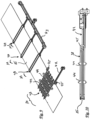
- Fig. 9 shows a perspective oblique view of a workpiece 15 to be machined, whereby the double belt press only has one in a main heating zone 10 (see also Fig. 1 ) arranged, inductively acting first heating element 38 with a connection element 42 and a further inductively acting heating element 39, 40 and 41 arranged in intermediate heating zones 11 with a collective connection element 43 are shown schematically.
- the first heating element 38 is guided in a plurality of heating loops, one above the workpiece 15 and the other below the workpiece 15.
- the second heating element 39, the third heating element 40 and the fourth heating element 41 each have a heating loop above and a heating loop below the workpiece 15.
- a controllable AC source can be used to supply power and cooling water, or, without a collective connection element, individually and directly with a controllable AC source. The latter offers the advantage of individual power control and thus individual heating in the holding zones 11.
- Fig. 10 shows the first heating element 38 guided around the workpiece 15 with the connecting element 42 in a side view.
- the illustrations of Fig. 9 and Fig. 10 differ slightly, especially in the connecting element 42, but this is not important here.
- the connecting element 42 is - as is the collective connecting element 43 ( Fig. 9 ) - prepared for contacting a preferably controllable AC source (not shown here).
- the heating loops of the first heating element 38 are mechanically stabilized against each other by two parallel cross-connectors 44 made of an electrically insulating material.
- the electrical connection between the upper loops and the lower loops of the first heating element 38 is realized by two transition pieces 45, each of which is guided around the edge of the workpiece 15 on the side facing the connection element 42.
- the first heating element 38 is open and can thus be guided laterally over the workpiece 15 or the workpiece 15 can be inserted laterally, so that maintenance or replacement of the first heating module 38 is possible even when the workpiece 15 is in the double-belt press.
- the illustrated path of the loops of the first heating element 38 above and below the workpiece results in the magnetic fields generated during operation of the first heating element 38 being aligned perpendicular to the center plane of the workpiece 15, i.e., transverse magnetic fields are generated.
- transverse fields can be technically and economically more efficient than longitudinal fields running parallel to the center plane when heating flat material, i.e., when the ratio of material width to thickness is high.
- the statements regarding the first heating element 38 also apply correspondingly to the other heating elements 39, 40 and 41 in the intermediate heating zones 11.
- the heating elements are also possible, e.g. those in which the part running below the workpiece 15 and the part running above the workpiece are movable independently of each other at least over a certain distance, e.g. in order to achieve the design according to Fig. 5
- the two parts can be assigned to separate connection elements, for example, or the electrical connection between the two components can be made via flexible or length-adjustable transition pieces.
- the vertical movement of the heating elements is important to ensure a largely constant distance between the heating element and the workpiece (see, for example, Figs. 4 and 5 ) requires only short distances in the mm or cm range.
Landscapes
- Engineering & Computer Science (AREA)
- Mechanical Engineering (AREA)
- Life Sciences & Earth Sciences (AREA)
- Chemical & Material Sciences (AREA)
- Composite Materials (AREA)
- Manufacturing & Machinery (AREA)
- Wood Science & Technology (AREA)
- Forests & Forestry (AREA)
- Physics & Mathematics (AREA)
- Electromagnetism (AREA)
- Press Drives And Press Lines (AREA)
- Casting Or Compression Moulding Of Plastics Or The Like (AREA)
Description
- Die Erfindung betrifft eine Vorrichtung zur pressenden Bearbeitung von Flachmaterial gemäß dem Oberbegriff des Anspruchs 1.
- Derartige Vorrichtungen können zum Beispiel für eine pressende Bearbeitung, insbesondere zum kontinuierlichen Laminieren und/oder Imprägnieren von flächigen Materialbahnen oder Materialsegmenten eingesetzt werden. Dabei können auch Heizelemente vorgesehen sein, die das Flachmaterial für die pressende Bearbeitung erwärmen. Bei der Vorrichtung kann es sich zum Beispiel um eine Doppelbandpresse handeln, die beispielsweise zur Herstellung von faserverstärktem Kunststoffen eingesetzt wird.
- Eine Vorrichtung der eingangs genannten Art ist aus der
EP 2 540 475 B1 bekannt. Hierbei handelt es sich um eine Doppelbandpresse, bei der zwei endlose Stahlbänder angetrieben und mit ihrem jeweiligen Arbeitstrum gegeneinander gepresst werden, wobei zwischen den Stahlbändern das zu bearbeitende Material in Transportrichtung geführt und gepresst wird. Mittels induktiv wirkender Heizelemente werden die Stahlbänder und damit mittelbar das zu pressende Flachmaterial für die Bearbeitung erhitzt. Bei dem Flachmaterial handelt es sich um einen Verbundwerkstoff aus Thermoplast und Filamenten. In Transportrichtung hinter den Heizelementen ist eine Presswalzen umfassende Kühleinheit vorgesehen, die über die Stahlbänder auf Ober- und Unterseite des Flachmaterials drückt. Für den Kühlzweck ist mindestens eine der Presswalzen mit Kühlwasser durchströmt. Die induktiven Heizelemente umfassen im Einsatz der Doppelbandpresse im Heizbereich jeweils die beiden Stahlbänder. Dabei sind die Heizelemente so ausgestaltet, dass sie eine untere Hälfte und eine obere Hälfte aufweisen, die an Verbindungspunkten zeitweise voneinander trennbar sind und somit eine Öffnungsbewegung des Arbeitstrums mindestens eines der Stahlbänder erlauben. Die Presswalzen erzeugen einen Linienkontakt zum Stahlband und somit jeweils eine Druckaufbringung, die zeitlich und örtlich stark limitiert ist. - Aus der
EP 0236905 B1 ist eine Vorrichtung zum Aufbringen einer Flächenpressung auf fortschreitende Werkstücke bekannt, die ebenfalls eine Doppelbandpresse darstellt. Der Pressdruck wird hierbei durch Druckplatten erzeugt, die beidseitig des jeweiligen Arbeitstrums der Pressbänder angeordnet sind. Der Transport des Flachmaterials wird durch geschlossene Bahnen von Rollensträngen ermöglicht, die zwischen der jeweiligen Druckplatte und dem zugehörigen Pressband geführt werden, auf den Druckplatten abrollen und dabei das Pressband und das zwischen den Pressbändern eingeklemmte Werkstück transportieren. Dabei wird vorgeschlagen, dass die Rollen an jedem Rollenstrang form- und/oder kraftschlüssig miteinander verbunden sind, mit einem ein Lagerspiel überschreitenden großen Ringspalt einen Achsstab umschließen und bis zur Achsanlage am Achsstab elastisch verformbar sind. Die elastische Verformbarkeit der Rollen kann toleranzausgleichend wirken. Zudem kann der genannte Ringspalt zum Schutz des Achsstabes wärmeisolierend wirken, sofern ein Aufheizen oder ein Abkühlen der Druckplatten erfolgt. Auf welche Weise eine aktive Beheizung erfolgen könnte, ist in diesem Stand der Technik nicht dargestellt. - Aus der
DE 24 14 762 C2 ist eine Doppelbandpresse bekannt, bei der eine Mehrzahl von Presswalzenpaaren vorgesehen sind, deren den Durchgang des Flachmaterials erlaubender Spaltabstand veränderbar ist. Der Spaltabstand wird über einen Druck geregelt, der mittels einer Druckmesseinrichtung in einer Kalibrierstrecke der Doppelbandpresse geregelt wird. Das Stahlband kann mittels auf dem jeweiligen Stahlband gleitenden Gleitschuhen, welche jeweils zwischen zwei Presswalzenpaaren angeordnet sind, beheizt werden. Die Gleitschuhe sorgen für Abrieb und erhöhen damit den Verschleiß der Doppelbandpresse. - Die
EP3 061 859 A1 offenbart eine Vorrichtung zur Herstellung von Folien unter Verwendung der Fasern von Altpapier, bei der dünnes bahnförmiges Flachmaterial zunächst auf einem Maschenband gebildet und über ein Transportband Pressvorgängen zugeführt wird. Das Pressen erfolgt durch Paare von Presswalzen, wobei zunächst ein erster Pressvorgang ohne Erwärmung des Flachmaterials und anschließend ein weiterer Pressvorgang bei geringerem Pressdruck und gleichzeitiger Erwärmung vorgesehen ist. Beide Pressvorgänge wirken unmittelbar auf das Flachmaterial. Eine Doppelbandpresse ist somit nicht realisiert. Die Beheizung des Flachmaterials kann über in den wärmenden Pressrollen vorgesehenen Halogen-Heizstrahlern erfolgen. - Es ist offenbart, die Presswalzen mit einer elastischen Schicht, z.B. aus Kunststoff zu versehen. Dabei sollen die elastischen Eigenschaften der Presswalzen dafür sorgen, den Kontakt der Presswalzen zueinander über deren gesamte axiale Länge zu gewährleisten.
- Aus der
WO2010/031364 A1 ist eine Vorrichtung zur Herstellung von Verbundwerkstoffbauteilen bekannt, bei der eine abrollende walzenförmige Andruckeinheit mit elastisch flexiblem Andruckkissen auf das auf einem festen Untergrund liegende bandförmige Werkstück presst, wobei letzteres unmittelbar vor dem Anpressen mit Laserstrahlung erhitzt wird. Ein Pressrollenpaar mit gegeneinander arbeitenden Pressrollen ist nicht offenbart. Es sind besondere Maßnahmen zum Schutz des Andruckkissens vor Überhitzung durch auftreffende Laserstrahlung vorgesehen, wie z.B. ein für Laserstrahlung (teil)transparentes Material des Andruckkissens, eine Abschattung des Andruckkissens gegenüber der Laserstrahlung oder ein durch das Andruckkissen hindurchgeführtes Kühlfluid. Das elastisch flexible Andruckkissen dient hier zum Ausgleich von Höhenunterschieden an dreidimensionalen Werkstückoberflächen beim Auftrag von Bandmaterial. - Der Erfindung liegt das technische Problem zugrunde, eine Vorrichtung der eingangs genannten Art zur Verfügung zu stellen, welche eine günstigere Druckverteilung der auf das Flachmaterial wirkenden Pressrollen ermöglicht.
- Diese Aufgabe wird bei einer Vorrichtung der eingangs genannten Art durch das kennzeichnende Merkmal des Anspruchs 1 gelöst. Bevorzugte Ausführungsbeispiele der erfindungsgemäßen Vorrichtung ergeben sich aus den abhängigen Ansprüchen.
- Gemäß Anspruch 1 ist eine Vorrichtung gemäß dem Oberbegriff des Anspruchs 1 dadurch gekennzeichnet, dass beide Pressrollen des Pressrollenpaares oder mindestens eines der Pressrollenpaare zumindest an ihrem Umfang in radialer Richtung eine gegenüber Stahlpressrollen erhöhte elastische Verformbarkeit aufweisen.
- Gegenüber dem aus dem Stand der Technik bei stationären Pressrollenpaaren bekannten harten Pressrollen bewirkt die elastische Verformbarkeit die Verteilung der Presskraft auf eine größere Fläche. Dieser Flächendruck hat gegenüber denen von bekannten Stahlwalzen oder Stahlpressrollen bekannten Linienkontakt eine erhöhte Druckaufbringungszeit und somit eine verbesserte und homogenere Presswirkung zur Folge.
- Gegenüber dem Einsatz von fluidischen Druckkissen, die ebenfalls eine flächige Druckzone erzeugen können, ist der anlagentechnische Aufwand wesentlich geringer und stark verschleißende Dichtungssysteme werden vermieden. Die ebenfalls denkbare Erzeugung flächiger Druckzonen durch den Einsatz von Gleitplatten würde stark limitierte Prozessdrücke sowie einen erhöhten Verschleiß zur Folge haben. Gemäß der Erfindung wird demgegenüber trotz der abrollenden Bewegung der Pressrollen ein Flächendruck ermöglicht.
- Die erfindungsgemäße Vorrichtung kann vorteilhaft so ausgebildet werden, dass mindestens zwei in Transportrichtung hintereinander angeordnete Pressrollenpaare vorhanden sind. Insbesondere vorteilhaft ist die erfindungsgemäße Vorrichtung, da sie als eine Doppelbandpresse ausgebildet ist. In diesem Fall wirkt das mindestens eine Pressrollenpaar mittelbar, nämlich über jeweils eines der Bänder auf das Flachmaterial. Die elastische Verformbarkeit der Rollen des mindestens einen Pressrollenpaares ist dabei schonend für die verwendeten Bänder, ohne dass der Vorteil des Flächendruckes gegenüber dem reinen Linienkontakt verloren geht. Im Fall der Doppelbandpresse, bei der in der Regel mindestens eines der Bänder angetrieben ist, bilden das Bandpaar und das mindestens eine Pressrollenpaar die Mittel zum Transport des zu bearbeitenden Flachmaterials.
- Die erfindungsgemäße Vorrichtung weist mindestens ein Heizelement zur Erwärmung des Flachmaterials auf. Heizelemente werden typischerweise für die Herstellung von Verbundmaterial oder zum Laminieren eingesetzt. Für die Erfindung können ein oder mehrere Heizelemente sinnvoll sein. Auch wenn in der folgenden Darstellung der Erfindung zur sprachlichen Vereinfachung zumeist die Heizelemente im Plural genannt sind, so betrifft die Erfindung auch entsprechende Ausführungsvarianten mit nur einem Heizelement.
- In der Doppelbandpresse können die Heizelemente mittelbar über die Bänder der Doppelbandpresse auf das Flachmaterial wirken. Erfindungsgemäß wird eine induktive Beheizung eingesetzt. Ein Induktor oder mehrere Induktoren sind vorzugsweise beidseitig der Arbeitstrume der Pressenbänder, angeordnet.
- Die erfindungsgemäße Vorrichtung kann auch so ausgebildet sein, dass mindesten eine Teilanzahl der Heizmittel ausgebildet ist, Magnetfelder zu erzeugen, welche eine überwiegende, senkrecht zu einer Mittelebene des Flachmaterials ausgerichtete Magnetfeldkomponente aufweisen. Dies kann mittels eines Flachinduktors oder eines ähnlich aufgebauten Induktors mit entsprechender Wirkung realisiert werden. So kann zum Beispiel vorgesehen sein, dass die Heizmittel oder zumindest eine Teilanzahl der Heizmittel zumindest streckenweise einen mäanderförmigen Verlauf aufweisen. Der mäanderförmige Verlauf kann dabei derart ausgerichtet sein, dass die Schleifen des Mäanders im Einsatz parallel zur Mittelebene des zu beheizenden Flachmaterials verlaufen.
- Des Weiteren kann vorgesehen sein, dass zumindest eine Teilanzahl der Heizmittel ausgebildet ist, eine Teilstrecke des zu beheizenden Flachmaterials U-förmig zu umfassen. In diesem Fall können die Induktoren derart ausgestaltet sein, dass sie über eine Längsseite des Flachmaterials in eine Arbeitsposition geschoben werden können. Ein vollständiges Umschließen des Flachmaterials ist damit nicht gegeben, weshalb eine mit einem Öffnen und Schließen elektrischer Kontakte verbundene Relativbewegung zweier Teile desselben Induktors zueinander nicht erforderlich ist.
- Die Wirkung des Heizelements auf das zu beheizende Gut kann erheblich vom Abstand Gut abhängen, insbesondere gilt dies für eine induktive Heizung mit ihrer Wechselwirkung zum induktiv ankoppelnden Material. Letzteres kann das zu bearbeitende Flachmaterial sein. Im Falle der Doppelbandpresse werden die Induktionsströme jedoch in der Regel im Bandmaterial der Doppelbandpresse erzeugt, das dann wiederum konduktiv das zu bearbeitende Flachmaterial erwärmt. Die elastische Verformbarkeit der Pressrollen mindestens eines der Pressrollenpaare kann dazu führen, dass sich die Position einer parallel zur Transportrichtung und parallel zu den Drehachsen der Pressrollen verlaufenden Mittelebene des Flachmaterials senkrecht zu dieser Mittelebende verschiebt. Die Verschiebung kann z.B. erfolgen, wenn beim Druckaufbau die Position der Drehachse eines der Pressrollen eines Pressrollenpaares in der Vorrichtung konstant bleibt, während die Drehachse der anderen Pressrolle sich verschiebt.
- Um nun eine möglichst gut reproduzierbare Erwärmung des Flachmaterials gewährleisten zu können, kann es insbesondere vorteilhaft sein, die erfindungsgemäße Vorrichtung so auszubilden, dass Mittel vorgesehen sind, die eine Anpassung der Position des mindestens einen Heizelements an die Position der Mittelebene ermöglichen.
- Eine solche Anpassung kann durch eine passive Nachführung des mindestens einen Heizelements erfolgen, zum Beispiel durch Abstandshalter zwischen dem Flachmaterial bzw. dem zugehörigen Band der Doppelbandpresse und dem mindestens einen Heizelement. Ein solcher Abstandshalter kann zum Beispiel über ein abrollendes oder gleitendes Distanzelement bewirkt werden. Gleichzeitig können elastisch wirkende Kräfte das mindesten einen Heizelement in Richtung auf das Flachmaterial oder das zugehörige Band der Doppelbandpresse drücken. Um eine Verschiebung der Heizelemente parallel zu Mittelebende des Flachmaterials zu vermeiden, können Führungsmittel vorgesehen werden.
- Es kann aber auch vorteilhaft sein, die erfindungsgemäße Vorrichtung so auszubilden, dass der Abstand der Heizelemente zur Mittelebene des Flachmaterials durch Mittel zur Steuerung oder Regelung dieses Abstandes realisiert wird. Diese Mittel können zum Beispiel Elektromotoren und Linearführungen umfassen, wobei die Steuerung oder Regelung auf Sensorwerte von Abstandssensoren basieren kann, die die Position der Mittelebene relativ zu den Drehachsen der Pressrollen ermitteln. Dies hat den Vorteil, dass anders als bei den passiven Abstandshaltern bewusst Änderungen im Abstand herbeigeführt werden können, um das Maß oder die Art und Weise der Erwärmung zusätzlich beeinflussen zu können.
- Es kann auch vorteilhaft sein, die erfindungsgemäße Vorrichtung so auszubilden, dass mindestens zwei Pressrollenpaare steuer- oder regelbar mit zueinander unterschiedlichen Presskräften beaufschlagbar sind. Auf diese Weise können unterschiedliche Druckprofile eingestellt werden, zum Beispiel mit über den Verlauf des Pressbereichs sich ändernden Drücken.
- Die erfindungsgemäße Vorrichtung kann auch so ausgebildet sein, dass mindestens eine der Rollen mindestens eines Rollenpaares einen Hohlraum für die Durchführung eines Kühlfluids aufweist. Hierdurch wird das elastische Material am Umfang der Pressrollen gegen möglicherweise schädliche hohe Temperaturen geschützt.
- Des Weiteren kann es vorteilhaft sein, die erfindungsgemäße Vorrichtung so auszubilden, dass mindestens eine der Pressrollen mindestens eines Pressrollenpaares am äußeren Umfang durch eine wärmeisolierende Schicht geschützt ist. Hierdurch ist ein weiterer wirkungsvoller Schutz der jeweiligen Pressrolle gegen den Einfluss der Temperatur des Flachmaterials beziehungsweise des Bandes der Doppelbandpresse gegeben. Die wärmeisolierende Schicht kann fester Bestandteil der Pressrolle sein. Alternativ kann die wärmeisolierende Schicht aber auch durch ein gesondertes, um einen Teilumfang der Rolle geführtes Band gebildet sein. Dies hat den Vorteil, dass die wärmeisolierende Schicht leicht auswechselbar ist und/oder bei seinem Umlauf durch eine von der Pressrolle beabstandete Kühlzone geführt werden kann. Als Materialien für die wärmeisolierende Schicht oder das wärmeisolierende Band können z.B. textile Strukturen sein, beispielsweise aus Glas, Carbon, Aramid, Basalt oder Hochleistungselastomere, wie z.B. Kalrez ® von DuPont ™, oder beschichtete Metallbänder. Vorteilhaft sind eine geringe Wärmeleitfähigkeit, hohe Temperaturbeständigkeit, Druck- und Abriebfestigkeit sowie Elastizität zumindest in Umfangrichtung der Pressrolle. Letzteres ist insbesondere dann vorteilhaft, wenn eine Verformung der elastisch verformbaren Schicht zu einer Umfangsänderung derselben führt, der die wärmeisolierende Schicht folgen muss.
- Schließlich kann die erfindungsgemäße Vorrichtung so ausgeführt werden, dass im Einsatz ein Kühlfluid von außen auf den Umfang der Pressrolle und/oder auf die Stirnseiten der Pressrolle gerichtet wird, wodurch eine zusätzliche Abkühlwirkung gegeben ist.
- Vorteilhafte Ausführungsformen der erfindungsgemäßen Vorrichtung werden im Folgenden anhand von Figuren dargestellt.
- Es zeigt schematisch:
- Fig.1:
- eine Doppelbandpresse,
- Fig.2:
- ein Pressrollenpaar vor und nach dem Druckaufbau mit Heizelementen und zu bearbeitendem Flachmaterial ohne Heizmittelnachführung,
- Fig. 3:
- ein Pressrollenpaar vor und nach dem Druckaufbau mit Heizelementen und zu bearbeitendem Flachmaterial mit Heizelementnachführung,
- Fig. 4:
- das Prinzip der Heizmittelnachführung mit Abstandshaltern,
- Fig. 5:
- das Prinzip der motorischen Heizelementnachführung,
- Fig. 6:
- Pressrolle mit integrierter wärmeisolierender Schicht,
- Fig. 7:
- Pressrolle mit gesondertem, um eine Umlenkrolle geführtem Wärmeisolationsband,
- Fig. 8:
- Pressrolle mit gesondertem, um zwei Umlenkrollen geführtem Wärmeisolationsband,
- Fig. 9:
- perspektivisch in seitlicher Aufsicht ein Werkstück mit induktiv wirkenden Heizelementen und
- Fig. 10:
- ein das Werkstück umfassendes induktives Heizelement in einer Seitenansicht.
-
Fig. 1 zeigt schematisch im seitlichen Querschnitt eine Doppelbandpresse mit einem oberen Pressenband 1 und einem unteren Pressenband 2. Die endlosen Pressenbänder 1 bzw. 2 sind jeweils um eine obere Antriebsrolle 3 bzw. untere Antriebsrolle 4 sowie um eine obere Umlenkrolle 5 bzw. eine untere Umlenkrolle 6 geführt. Zwischen einem Arbeitstrum 7 des oberen Pressenbandes 1 und einem Arbeitstrum 8 des unteren Pressenbandes 2 wird hier nicht dargestelltes, zu bearbeitendes Flachmaterial geführt, das in einer Transportrichtung (inFig. 1 von links nach rechts) von den umlaufenden Pressenbändern 1 und 2 mitgeführt wird. Entlang der Arbeitstrume 7 und 8 sind eine Mehrzahl von Pressrollenpaaren 9 angeordnet, mit denen der obere Arbeitstrum 7 und der untere Arbeitstrum 8 gegen das zu bearbeitende, hier nicht dargestellte Flachmaterial gepresst werden. Des Weiteren sind entlang der Arbeitstrume 7 und 8 inFig. 1 nicht einzeln dargestellte Heizelemente in einer Hauptheizzone 10 und in Zwischenheizzonen 11 angeordnet, die induktiv wirken. Es ist entweder das Material der Pressenbänder 1 und 2 induktiv ankoppelnd oder das zu bearbeitende Flachmaterial. Durch die Vielzahl der Heizelemente und ihre Positionierung zwischen den Pressrollenpaaren 9 kann eine für die Bearbeitung des Flachmaterials erforderliche Temperatur über eine lange Strecke aufrechterhalten werden. Die hier dargestellte Anordnung von jeweils einer Zwischenheizzone 11 zwischen zwei Pressrollenpaaren 9 ist nur beispielhaft. Die Anzahl der Zwischenheizzonen 11 und die Anordnung der an die Zwischenheizzonen 11 angrenzenden Pressrollenpaare 9, z.B. einzeln oder in Gruppen zu zwei oder mehr Pressrollenpaaren 9, kann je nach Anforderungen des Betriebs der Doppelbandpresse anders gestaltet werden. In Transportrichtung gesehen am Ende der Arbeitstrume 7 und 8 sind optional Kühlstrecken 12 angeordnet. -
Fig. 2 zeigt schematisch ein Pressrollenpaar 9 mit einer oberen Pressrolle 13 und einer unteren Pressrolle 14, wobei in a) die Situation vor Aufbringen eines Pressdruckes und in b) die Situation unter einem bestimmten Pressdruck dargestellt ist. Zwischen den Pressrollen 13 und 14 ist schematisch ein zu bearbeitendes Werkstück 15 aus Flachmaterial dargestellt, wobei in der Darstellung die das Werkstück 15 zwischen sich nehmenden Pressenbänder 7 und 8 (sieheFig. 1 ) nicht erkennbar sind. Die Pressrollen 13 und 14 weisen auf ihrem äußeren Umfang einen elastisch verformbaren Bereich 16 auf. Der Anpressdruck von beiden Pressrollen 13 und 14 wird gemäßFig. 2 symmetrisch aufgebaut, d. h. aufgrund der Nachgiebigkeit des elastisch verformbaren Bereichs 16 bewegen sich die Drehachsen 17 bzw. 18 der Pressrollen 13 und 14 mit jeweils der gleichen Wegstrecke ΔI auf das Werkstück 15 zu, weshalb die vertikale Position einer Mittelebene 19 des Werkstückes 15 durch das Aufbringen des Pressdruckes nicht verändert wird.Fig. 2 zeigt außerdem schematisch die Position von Heizelementen 20, wie sie in der Hauptheizzone 10 oder in den Zwischenheizzonen 11 (sieheFig. 1 ) vorgesehen sein können. Der Abstand dieser Heizelemente 20 senkrecht zur Mittelebene 19 bleibt unverändert trotz der mit Aufbringen des Pressdruckes erzeugten Verschiebung der Positionen der Drehachsen 17 und 18. Um ein zur Mittelebene 19 symmetrisches Verfahren der Pressenrollenpaar 13 und 14 zu erreichen, ist jedoch ein erheblicher Regelungsaufwand zu betreiben. -
Fig. 3 zeigt eine zurFig. 2 ähnliche Situation. Gleiche Bezugszahlen beziehen sich auf gleiche Vorrichtungselemente, so dass auf die Beschreibung zuFig. 2 verwiesen werden kann. Die in der Teilfigur a) gezeigte Ausgangsposition der Pressrollen 13 und 14 ist identisch zu der Ausgangsposition inFig. 2a ). Ein Unterschied ist, dass die Drehachse 18 der unteren Pressrolle 14 in der Anordnung gemäßFig. 3 in ihrer Position fixiert ist. Zum Aufbringen des Pressdruckes wird somit lediglich die Drehachse 17 der oberen Pressrolle um eine Wegstrecke 2ΔI in Richtung auf die untere Drehachse 18 bewegt. Da die Verformung der Pressrollen 13 bzw. 14 aufgrund des ansonsten übereinstimmenden Aufbaus gleich ist, wird sich die Mittelebene 19 des Werkstückes 15 um die Wegstrecke ΔI auf die untere Pressrolle 14 zu bewegen. Um zu verhindern, dass durch das Aufbringen des Pressdruckes die Wirkung der Heizelemente 20 auf das Werkstück 15 verändern wird, ist vorgesehen, den Abstand der Heizelemente 20 zur Mittelebene 19 nicht zu verändern und die Heizelemente 20 ebenfalls um die Wegstrecke ΔI zu verfahren. Mit dieser Maßnahme wird somit der Vorteil des mittels des elastisch verformbaren Bereichs 16 erreichten Flächendruckes ohne Einschränkung durch eine ansonsten nur eingeschränkt reproduzierbare Wirkung der Heizelemente 20 auf das Werkstück 15 erreicht. -
Fig. 4 zeigt schematisch in einem Querschnitt senkrecht zur Materialtransportrichtung eine Doppelbandpresse mit zwei Heizelementen 20 von denen eines oberhalb und das andere unterhalb des Werkstückes 15 und der das Werkstück 15 zwischen sich aufnehmenden Pressenbänder 1 und 2 angeordnet ist. Die Heizelemente 20 werden derart an Halterungen 21 gehalten, dass während des Betriebs der Doppelbandpresse ein möglichst konstanter Abstand zwischen dem jeweiligen Heizelement 20 und dem zugehörigen Pressenband 1 bzw. 2 gegeben ist. Hierzu sind hier beispielhaft Abstandshalter 23 vorgesehen. Die Heizelemente 20 werden, um einer möglichen Vertikalbewegung des jeweiligen Pressenbandes 1 bzw. 2 folgen zu können, mit einer Kraft in Richtung des zugehörigen Pressenbandes 1 bzw. 2 gedrückt, die hier jeweils durch ein Federelement 22 symbolisiert ist. Diese Kraft kann sich für das obere der Heizelemente 20 auch aus seiner Gewichtskraft und einer der Gravitation entgegenwirkenden Stützkraft zusammensetzen, wobei die Stützkraft die Belastung des oberen Pressenbandes 1 reduzieren soll. Die Abstandshalter 23 sind vorzugsweise am jeweiligen Heizelement 20 fixiert und können am zugehörigen Pressenband 1 bzw. 2 abrollen. Es können selbstverständlich alternativ oder zusätzlich auch gleitende Abstandshalter vorgesehen werden. Für die Führung der Halterungen 21 sind Führungselemente 24 vorgesehen. -
Fig. 5 zeigt ebenfalls im Querschnitt eine Doppelbandpresse, bei der - anders als nachFig. 4 - der Abstand zwischen den Heizelementen 20 und dem zwischen den Pressenbändern 1 und 2 angeordneten Werkstück 15 mittels Elektromotoren 25 und Linearführungen 26 eingestellt wird. Als Basisgröße für die über eine Steuer-/ oder Regeleinrichtung 28 erfolgende Steuerung oder Regelung der Elektromotoren 25 dienen Sensorwerte von Abstandssensoren 27, die beispielsweise mechanisch, optisch oder kapazitiv messen. -
Fig. 6 zeigt schematisch eine auf das obere Pressenband 1 drückende Pressrolle 29 mit einer fest an ihrem äußeren Umfang angeordneten wärmeisolierenden Schicht 30, die unmittelbar auf einen elastisch verformbaren Bereich 31 der Pressrolle aufgebracht ist. Der elastisch verformbare Bereich 31 wiederum umgibt einen Hohlzylinder 33 aus einem demgegenüber steifen Material, z.B. Edelstahl. Ein innerer Hohlraum 32 des Hohlzylinders 33 kann für den Durchfluss eines Kühlfluids genutzt werden. Der elastisch verformbare Bereich 31, z.B. aus Silikon, kann beispielhaft eine Stärke von 1 bis 20mm, vorzugsweise 5 bis 15 mm, aufweisen und eine Härte zwischen beispielsweise 20 Shore-A und 65 Shore-A, vorzugsweise zwischen 50 Shore-A und 60 Shore-A. -
Fig. 7 zeigt eine Pressrolle 34 bei der die wärmeisolierende Schicht nicht auf dem vollständigen Umfang fixiert ist, sondern durch ein umlaufendes Band 35 realisiert wird, welches nur auf einem Teil seines Umfangs am elastisch verformbaren Bereich 36 anliegt und ansonsten mit Abstand zur Pressrolle 34 über eine Umlenkrolle 37 geführt ist. In dem beabstandeten Bereich zwischen Pressrolle 34 und Umlenkrolle 37 besteht eine verbesserte Möglichkeit der gesonderten Kühlung des Bandes 35. Zudem ist das verschließbehaftete Band 35 leicht austauschbar.Fig. 8 zeigt eine zurFig. 7 ähnliche weitere Variante, bei der das Band 35 jedoch über zwei Umlenkrollen 37 geführt ist, wodurch ein geringerer Umschlingungswinkel des Bandes 35 mit der Pressenrolle 34 realisiert wird und eine bessere Kühlmöglichkeit gegeben sein kann. wegen der weiteren Einzelheiten wird auf die Beschreibung zuFig. 7 verwiesen. - Für sämtliche Ausführungsformen gilt, dass die Pressrollen nicht zwangsläufig Hohlzylinder sein müssen. Es sind auch andere Formen mit oder ohne Durchgänge für ein Kühlfluid denkbar.
-
Fig. 9 zeigt in perspektivischer Schrägaufsicht ein zu bearbeitendes Werkstück 15, wobei von der Doppelbandpresse lediglich ein in einer Hauptheizzone 10 (siehe auchFig. 1 ) angeordnetes, induktiv wirkendes erstes Heizelement 38 mit einem Anschlusselement 42 und jeweils ein in Zwischenheizzonen 11 angeordnetes weiteres induktiv wirkendes Heizelement 39, 40 bzw. 41 mit einem Sammelanschlusselement 43 schematisch gezeigt sind. In der Hauptheizzone 10 ist das erste Heizelement 38 in einer Vielzahl von Heizschleifen zum einen oberhalb des Werkstückes 15 und zum anderen unterhalb des Werkstückes 15 geführt. In den Zwischenheizzonen 11 weist das zweite Heizelement 39, das dritte Heizelement 40 und das vierte Heizelement 41 jeweils eine Heizschleife oberhalb und eine Heizschleife unterhalb des Werkstückes 15 auf. In den Zwischenheizzonen 11 sind auch mehr als jeweils eine Heizschleife und in unterschiedlichen Zwischenheizzonen 11 unterschiedliche Anzahlen von Heizschleifen denkbar. Die Heizelemente 39, 40 und 41 können dabei wie inFig. 9 dargestellt über das Sammelanschlusselement 43 gemeinsam durch eine hier nicht dargestellte, vorzugsweise steuerbare Wechselstromquelle mit Leistung und Kühlwasser versorgt werden, oder ohne Sammelanschlusselement einzeln direkt mit jeweils einer steuerbaren Wechselstromquelle. Letzteres bietet den Vorteil der einzelnen Leistungsregelung und damit individuellen Erwärmung in den Haltezonen 11. -
Fig. 10 zeigt das erste um das Werkstück 15 geführte erste Heizelement 38 mit dem Anschlusselement 42 in einer Seitenansicht. Die Darstellungen vonFig. 9 und Fig. 10 unterscheiden sich leicht, insbesondere im Anschlusselement 42, was aber hier keine Bedeutung haben soll. Das Anschlusselement 42 ist - wie auch das Sammelanschlusselement 43 (Fig. 9 ) - für die Kontaktierung an einer hier nicht dargestellten, vorzugsweise steuerbaren Wechselstromquelle vorbereitet. Die Heizschleifen des ersten Heizelements 38 sind untereinander mit zwei parallel zueinander verlaufenden Querverbindern 44 aus einem elektrisch isolierenden Material mechanisch gegeneinander stabilisiert. - Die elektrische Verbindung zwischen den oberen Schleifen und den unteren Schleifen des ersten Heizelements 38 ist durch zwei Übergangsstücke 45 realisiert, die jeweils auf der dem Anschlusselement 42 zugewandten Seite um die Kante des Werkstücks 15 geführt sind. Auf der den Übergangsstücken 45 abgewandten Seite ist das erste Heizelement 38 offen und kann somit seitlich über das Werkstück 15 geführt werden oder das Werkstück 15 kann seitlich eingeführt werden, sodass eine Wartung oder ein Austausch des ersten Heizmoduls 38 auch bei in der Doppelbandpresse befindlichem Werkstück 15 möglich ist.
- Der dargestellte Verlauf der Schleifen des ersten Heizelements 38 oberhalb und unterhalb des Werkstückes führt dazu, dass sich die im Betrieb des ersten Heizelements 38 erzeugten Magnetfelder senkrecht zur Mittelebene des Werkstückes 15 ausrichten, d.h. es werden magnetische Querfelder erzeugt. Derartige Querfelder können bei der Erwärmung von Flachmaterial, das heißt bei großem Verhältnis von Materialbreite zu Materialdicke, technisch und wirtschaftlich effizienter sein als parallel zur Mittelebene verlaufende Längsfelder.
- Die Ausführungen zum ersten Heizelement 38 gelten in entsprechender Weise auch für die weiteren Heizelemente 39, 40 und 41 in den Zwischenheizzonen 11.
- Selbstverständlich sind auch andere Ausführungsvarianten für die Heizelemente möglich, z.B. solche, bei denen der unter dem Werkstück 15 verlaufende Teil und der oberhalb des Werkstückes verlaufende Teil zumindest über eine gewisse Wegstrecke unabhängig voneinander bewegbar sind, z.B. um die Ausführungsform gemäß
Fig. 5 realisieren zu können. Hierfür können die beiden Teile z.B. separaten Anschlusselementen zugeordnet werden oder die elektrische Verbindung zwischen den beiden Bestandteilen erfolgt über flexible oder in der Länge veränderbare Übergangsstücke. Es ist zu beachten, dass die Vertikalbewegung der Heizelemente für die Gewährleistung eines weitgehend konstanten Abstandes zwischen Heizelement und Werkstück (siehe z.B.Fig. 4 und 5 ) nur geringe Strecken im mm- oder cm-Bereich erfordert. -
1 Oberes Pressenband 32 Hohlraum 2 Unteres Pressenband 33 Hohlzylinder 3 Obere Antriebsrolle 34 Pressrolle 4 Untere Antriebsrolle 35 Band 5 Umlenkrolle 36 elastisch verformbarer Bereich 6 Umlenkrolle 37 Umlenkrolle 7 Arbeitstrum oberes Pressenband 38 erstes Heizelement 8 Arbeitstrum unteres Pressenband 39 zweites Heizelement 9 Pressrollenpaar 40 drittes Heizelement 10 Hauptheizzone 41 viertes Heizelement 11 Zwischenheizzone 42 Anschlusselement 12 Kühlstrecke 43 Sammelanschlusselement 13 obere Pressrolle 44 Querverbinder 14 untere Pressrolle 45 Übergangsstück 15 Werkstück 16 elastisch verformbarer Bereich 17 Drehachse 18 Drehachse 19 Mittelebene 20 Heizelement 21 Halterung 22 Federelement 23 Abstandshalter 24 Führungselement 25 Elektromotor 26 Linearführung 27 Abstandssensoren 28 Steuer-/ oder Regeleinrichtung 29 Pressrolle 30 wärmeisolierende Schicht 31 elastisch verformbarer Bereich
Claims (12)
- Vorrichtung zur pressenden Bearbeitung von Flachmaterial, umfassend Mittel zum Transport des Flachmaterials (15) in eine Transportrichtung und mindestens ein in Transportrichtung stationäres, beidseitig auf das Flachmaterial (15) wirkendes Pressrollenpaar (9), wobei die Vorrichtung eine Doppelbandpresse ist, und Heizmittel (20) zur Erwärmung des Flachmaterials (15),wobei zumindest eine Teilanzahl der Heizmittel (20) induktiv wirkt,dadurch gekennzeichnet, dassbeide Pressrollen (13, 14, 29, 34) des Pressrollenpaares (9) oder beide Pressrollen (13, 14, 29, 34) mindestens eines der Pressrollenpaare (9) zumindest an ihrem Umfang in radialer Richtung eine gegenüber Stahlpressrollen erhöhte elastische Verformbarkeit aufweisen.
- Vorrichtung nach Anspruch 1, dadurch gekennzeichnet, dass die Pressrollen (13, 14, 29, 34) mit erhöhter elastischer Verformbarkeit jeweils einen elastisch verformbaren Bereich (16, 31, 36) mit einer Stärke von 1 bis 20mm, vorzugsweise 5 bis 15 mm, und einer Härte zwischen 20 Shore-A und 65 Shore-A, vorzugsweise zwischen 50 Shore-A und 60 Shore-A aufweisen, dass die Pressrollen (13, 14, 29, 34) mit erhöhter elastischer Verformbarkeit jeweils eine fest an ihrem äußeren Umfang angeordnete wärmeisolierende Schicht (30) aufweisen, wobei die wärmeisolierende Schicht (30) jeweils unmittelbar auf den elastisch verformbaren Bereich (16, 31, 36) der Pressrolle (13, 14, 29, 34) aufgebracht ist und dass der elastisch verformbare Bereich (16, 31, 36) jeweils einen Hohlzylinder (33) aus einem demgegenüber steiferen Material umgibt.
- Vorrichtung nach einem der vorherigen Ansprüche, dadurch gekennzeichnet, dass mindestens zwei in Transportrichtung hintereinander angeordnete Pressrollenpaare (9) vorhanden sind.
- Vorrichtung nach einem der vorherigen Ansprüche, dadurch gekennzeichnet, dass die Heizmittel (20) mittelbar über die Bänder (1, 2) der Doppelbandpresse auf das Flachmaterial (15) wirken.
- Vorrichtung nach einem der vorherigen Ansprüche, dadurch gekennzeichnet, dass mindesten eine Teilanzahl der Heizmittel (20) ausgebildet ist, Magnetfelder zu erzeugen, welche eine überwiegende, senkrecht zu einer Mittelebene (19) des Flachmaterials (15) ausgerichtete Magnetfeldkomponente aufweisen.
- Vorrichtung nach einem der vorherigen Ansprüche, dadurch gekennzeichnet, dass die Heizmittel (20) oder zumindest eine Teilanzahl der Heizmittel (20) zumindest streckenweise einen mäanderförmigen Verlauf aufweisen.
- Vorrichtung nach einem der vorherigen Ansprüche, dadurch gekennzeichnet, dass zumindest eine Teilanzahl der Heizmittel (20) ausgebildet ist, eine Teilstrecke des zu beheizenden Flachmaterials (15) U-förmig zu umfassen.
- Vorrichtung nach einem der vorherigen Ansprüche, gekennzeichnet durch Mittel zur Steuerung oder Regelung eines Abstandes der Heizmittel (20) zu einer parallel zur Transportrichtung und parallel zu den Drehachsen der Pressrollen (13, 14, 29, 34) verlaufenden Mittelebene (19) des Flachmaterials (15).
- Vorrichtung nach einem der vorherigen Ansprüche, gekennzeichnet durch Abstandshalter (23) zur Sicherstellung eines konstanten Abstandes der Heizmittel (20) zu einer parallel zur Transportrichtung verlaufenden Mittelebene (19) des Flachmaterials (15).
- Vorrichtung nach einem der vorherigen Ansprüche, dadurch gekennzeichnet, dass mindestens zwei Pressrollenpaare (9) steuer- oder regelbar mit unterschiedlichen Presskräften beaufschlagbar sind.
- Vorrichtung nach einem der vorherigen Ansprüche, dadurch gekennzeichnet, dass mindestens eine der Pressrollen (13, 14, 29, 34) mindestens eines Pressrollenpaares (19) einen Hohlraum (32) für die Durchführung eines Kühlfluids aufweist.
- Vorrichtung nach einem der vorherigen Ansprüche, gekennzeichnet durch Kühlmittel, welche im Einsatz ein Kühlfluid von außen auf den Pressrollenumfang und/oder auf die Pressrollenstirnseiten richten.
Applications Claiming Priority (3)
| Application Number | Priority Date | Filing Date | Title |
|---|---|---|---|
| DE102018130019.0A DE102018130019B4 (de) | 2018-11-27 | 2018-11-27 | Vorrichtung zur pressenden Bearbeitung von Flachmaterial |
| PCT/DE2019/101018 WO2020108704A1 (de) | 2018-11-27 | 2019-11-27 | Vorrichtung zur pressenden bearbeitung von flachmaterial |
| EP19839321.7A EP3887138B1 (de) | 2018-11-27 | 2019-11-27 | Vorrichtung zur pressenden bearbeitung von flachmaterial |
Related Parent Applications (2)
| Application Number | Title | Priority Date | Filing Date |
|---|---|---|---|
| EP19839321.7A Division EP3887138B1 (de) | 2018-11-27 | 2019-11-27 | Vorrichtung zur pressenden bearbeitung von flachmaterial |
| EP19839321.7A Division-Into EP3887138B1 (de) | 2018-11-27 | 2019-11-27 | Vorrichtung zur pressenden bearbeitung von flachmaterial |
Publications (3)
| Publication Number | Publication Date |
|---|---|
| EP4105006A1 EP4105006A1 (de) | 2022-12-21 |
| EP4105006B1 true EP4105006B1 (de) | 2025-06-18 |
| EP4105006C0 EP4105006C0 (de) | 2025-06-18 |
Family
ID=69182442
Family Applications (2)
| Application Number | Title | Priority Date | Filing Date |
|---|---|---|---|
| EP19839321.7A Active EP3887138B1 (de) | 2018-11-27 | 2019-11-27 | Vorrichtung zur pressenden bearbeitung von flachmaterial |
| EP22177899.6A Active EP4105006B1 (de) | 2018-11-27 | 2019-11-27 | Vorrichtung zur pressenden bearbeitung von flachmaterial |
Family Applications Before (1)
| Application Number | Title | Priority Date | Filing Date |
|---|---|---|---|
| EP19839321.7A Active EP3887138B1 (de) | 2018-11-27 | 2019-11-27 | Vorrichtung zur pressenden bearbeitung von flachmaterial |
Country Status (8)
| Country | Link |
|---|---|
| US (1) | US20220024158A1 (de) |
| EP (2) | EP3887138B1 (de) |
| JP (1) | JP7337160B2 (de) |
| KR (1) | KR102560583B1 (de) |
| CN (1) | CN113474153B (de) |
| DE (2) | DE102018130019B4 (de) |
| ES (1) | ES2888373T1 (de) |
| WO (1) | WO2020108704A1 (de) |
Families Citing this family (7)
| Publication number | Priority date | Publication date | Assignee | Title |
|---|---|---|---|---|
| JP2022076366A (ja) * | 2020-11-09 | 2022-05-19 | 株式会社Ihi物流産業システム | ダブルベルトプレス装置 |
| JPWO2023021868A1 (de) * | 2021-08-20 | 2023-02-23 | ||
| CN115071113A (zh) * | 2022-05-31 | 2022-09-20 | 广东聚石复合材料有限公司 | 热塑性蜂窝板翘曲矫正装置及工艺 |
| TWI804438B (zh) * | 2022-09-23 | 2023-06-01 | 安能複材科技股份有限公司 | 拉擠纖維板材之拉擠成型機構 |
| DE102023118977B3 (de) | 2023-07-18 | 2024-11-07 | Azl Aachen Gmbh | Pressvorrichtung und Verfahren zur kontinuierlichen Imprägnierung von faserverstärkten, thermoplastischen Flachhalbzeugen |
| DE102023135183A1 (de) * | 2023-12-14 | 2025-06-18 | Friedrich-Alexander-Universität Erlangen-Nürnberg, in Vertretung des Freistaates Bayern | Vorrichtung und Verfahren zur Herstellung eines Folienverbunds |
| JP7702175B1 (ja) | 2024-08-21 | 2025-07-03 | 株式会社Sgic | プレス装置 |
Family Cites Families (24)
| Publication number | Priority date | Publication date | Assignee | Title |
|---|---|---|---|---|
| DE2261322A1 (de) * | 1972-12-15 | 1974-06-27 | Adolf Fritz Gmbh | Beschickvorrichtung sowie verfahren zum zufuehren von plattenfoermigem pressgut in einer presse |
| DE2414762C2 (de) | 1974-03-27 | 1983-03-03 | Peter 5439 Bretthausen Voelskow | Doppelbandpresse zur kontinuierlichen Herstellung einer endlosen Plattenbahn aus verpreßten vegetabilischen Stoffen |
| JPS56167353A (en) * | 1980-05-26 | 1981-12-23 | Mitsubishi Electric Corp | Pressure-welding type semiconductor device |
| DE3608487A1 (de) | 1986-03-14 | 1987-09-17 | Hymmen Theodor Gmbh | Vorrichtung zum aufbringen einer flaechenpressung auf fortschreitende werkstuecke |
| JPH0471657A (ja) * | 1990-07-09 | 1992-03-06 | Toray Ind Inc | 成形ロール |
| JPH05212593A (ja) * | 1992-01-23 | 1993-08-24 | Kurt Held | ダブルベルトプレス |
| DE19961365A1 (de) * | 1999-12-17 | 2001-06-21 | Esselte Nv | Laminierwalze für Laminierpressen sowie Verfahren zur Herstellung von Laminierwalzen |
| DE10214322B4 (de) * | 2002-03-28 | 2016-07-14 | Siempelkamp Maschinen- Und Anlagenbau Gmbh | Kontinuierliche Presse zum Verpressen von Pressgutmatten zu Pressgutplatten |
| DE10322227A1 (de) * | 2003-05-18 | 2004-12-09 | Dieffenbacher Gmbh + Co. Kg | Verfahren und Anlage zur Stahlbandführung in einer kontinuierlich arbeitenden Presse |
| DK2337670T3 (da) | 2008-09-18 | 2019-07-22 | Fraunhofer Ges Forschung | Fremgangsmåde og indretning til fremstilling af kompositmaterialekomponenter samt trykenhed |
| KR101293892B1 (ko) | 2010-02-22 | 2013-08-06 | (주)엘지하우시스 | 고주파 유도가열 더블스틸벨트 프레스 장치 |
| KR101209653B1 (ko) * | 2010-03-16 | 2012-12-07 | 주식회사 에스에프에이 | 스퍼터 장치 |
| US9005501B2 (en) * | 2011-08-17 | 2015-04-14 | Reifenhaeuser Gmbh & Co. Kg Maschinenfabrik | Method and apparatus for producing a film web from thermoplastic material and film produced thereby |
| DE102011089543A1 (de) * | 2011-12-22 | 2013-06-27 | Voith Patent Gmbh | Vorrichtung zur Kühlung von bewegtem Flachmaterial |
| DE202011110527U1 (de) * | 2011-12-22 | 2014-07-07 | Voith Patent Gmbh | Vorrichtung zur Kühlung von bewegtem Flachmaterial |
| CN103781208B (zh) * | 2012-10-17 | 2016-04-20 | 昆山渝榕电子有限公司 | 加热装置的导电结构 |
| JP6127901B2 (ja) * | 2013-10-21 | 2017-05-17 | セイコーエプソン株式会社 | シート製造装置、シート製造方法 |
| DE202014010747U1 (de) * | 2014-06-10 | 2016-07-04 | Kiener Maschinenbau Gmbh | Vorrichtung zur Bearbeitung einer Rückseite eines Bahnmaterials |
| DE102014112716A1 (de) * | 2014-09-03 | 2016-03-03 | Dieffenbacher GmbH Maschinen- und Anlagenbau | Kontinuierlich arbeitende Presse und Verfahren zum Betreiben solcher Pressen |
| JP6541965B2 (ja) | 2014-12-22 | 2019-07-10 | Toyo Tire株式会社 | シート状部材の溝加工装置及び方法 |
| CN204780535U (zh) * | 2015-07-01 | 2015-11-18 | 河南宝润机械有限公司 | 一种压路机辊轮 |
| US20170297295A1 (en) * | 2016-04-15 | 2017-10-19 | Honeywell International Inc. | Blister free composite materials molding |
| JP6334795B1 (ja) | 2017-09-05 | 2018-05-30 | プロセスシステム株式会社 | ダブルベルトプレス装置および誘導加熱プレスモジュール |
| KR102143643B1 (ko) * | 2018-08-24 | 2020-08-11 | 주식회사 엘지화학 | 전고체 전지용 전극 또는 고체 전해질의 제조 장치 |
-
2018
- 2018-11-27 DE DE102018130019.0A patent/DE102018130019B4/de active Active
-
2019
- 2019-11-27 CN CN201980089414.7A patent/CN113474153B/zh active Active
- 2019-11-27 JP JP2021530052A patent/JP7337160B2/ja active Active
- 2019-11-27 ES ES19839321T patent/ES2888373T1/es active Pending
- 2019-11-27 US US17/297,014 patent/US20220024158A1/en not_active Abandoned
- 2019-11-27 EP EP19839321.7A patent/EP3887138B1/de active Active
- 2019-11-27 DE DE112019005890.8T patent/DE112019005890A5/de active Pending
- 2019-11-27 EP EP22177899.6A patent/EP4105006B1/de active Active
- 2019-11-27 KR KR1020217019920A patent/KR102560583B1/ko active Active
- 2019-11-27 WO PCT/DE2019/101018 patent/WO2020108704A1/de not_active Ceased
Also Published As
| Publication number | Publication date |
|---|---|
| ES2888373T1 (es) | 2022-01-04 |
| KR102560583B1 (ko) | 2023-07-27 |
| US20220024158A1 (en) | 2022-01-27 |
| EP3887138C0 (de) | 2025-11-12 |
| WO2020108704A1 (de) | 2020-06-04 |
| EP4105006C0 (de) | 2025-06-18 |
| EP3887138B1 (de) | 2025-11-12 |
| JP2022509217A (ja) | 2022-01-20 |
| CN113474153B (zh) | 2023-10-13 |
| DE112019005890A5 (de) | 2021-10-21 |
| DE102018130019B4 (de) | 2021-02-25 |
| EP3887138A1 (de) | 2021-10-06 |
| CN113474153A (zh) | 2021-10-01 |
| JP7337160B2 (ja) | 2023-09-01 |
| KR20210097738A (ko) | 2021-08-09 |
| EP4105006A1 (de) | 2022-12-21 |
| DE102018130019A1 (de) | 2020-05-28 |
Similar Documents
| Publication | Publication Date | Title |
|---|---|---|
| EP3887138B1 (de) | Vorrichtung zur pressenden bearbeitung von flachmaterial | |
| DE3534478C2 (de) | Doppelbandpresse zum kontinuierlichen Verpressen von Werkstoffbahnen bei erhöhten Temperaturen | |
| DE10392944T5 (de) | Walzvorrichtung vom elektrisch beheizten Typ | |
| EP2722112B1 (de) | Vorrichtung und Verfahren zur kontinuierlichen Behandlung eines Metallbandes | |
| DE102008019720A1 (de) | Beheizte Prägewalze | |
| DE2243465B2 (de) | Kontinuierlich arbeitende presse | |
| EP0163864B1 (de) | Verfahren und Vorrichtung zum kontinuierlichen Verpressen von Werkstoffbahnen | |
| DE60033667T2 (de) | Nicht rotierendes, zylindrisches luftpolster zur erzeugung einer bandschwebung und verfahren zum stützen und führen eines endlosen flexiblen giessbandes | |
| DE102016110323B4 (de) | Fasertemperiereinrichtung, Faserappliziervorrichtung, Faserlegeanlage sowie Verfahren zum Temperieren | |
| EP1600277A2 (de) | Kühlvorrichtung | |
| DE102009023577A1 (de) | Presse, insbesondere kontinuierlich arbeitende Presse zur Herstellung von Werkstoffplatten | |
| EP1314819B1 (de) | Kalander und Verfahren zum Glätten einer Papier- oder Kartonbahn | |
| DE3138011A1 (de) | Doppelbandpresse | |
| EP0792966B1 (de) | Kalander zum Satinieren von Papier | |
| DE1717458U (de) | Einrichtung zum kontinuierlichen pressen. | |
| DE3743933A1 (de) | Verfahren und vorrichtung zur beheizung einer kontinuierlich arbeitenden heizplattenpresse | |
| DE102007043891A1 (de) | Kontaktrollenvorrichtung und Oberflächenbehandlungsanlage für Metallstrang | |
| DE102008029513B3 (de) | Heizvorrichtung zum induktiven Erwärmen einer Kalanderwalze | |
| DE3206558A1 (de) | Doppelbandpresse | |
| DE102020116749B3 (de) | Heizwalze für einen Vorwärmschrank und deren Herstellung, Vorwärmschrank sowie diesen umfassende Anlage | |
| DE102005019475A1 (de) | Kalander und Verfahren zum Behandeln einer Materialbahn | |
| EP3491269B1 (de) | Rollstabkette und kontinuierliche presse | |
| DE102009013601B4 (de) | Vorrichtung zum Walzen von flächigem Gut und Walze einer solchen Vorrichtung | |
| DE10141646C1 (de) | Vorrichtung zum im Durchlauf erfolgenden induktiven Erwärmen von metallischen Werkstücken | |
| DE102006017460B4 (de) | Beheizbare Kalanderwalze |
Legal Events
| Date | Code | Title | Description |
|---|---|---|---|
| PUAI | Public reference made under article 153(3) epc to a published international application that has entered the european phase |
Free format text: ORIGINAL CODE: 0009012 |
|
| STAA | Information on the status of an ep patent application or granted ep patent |
Free format text: STATUS: THE APPLICATION HAS BEEN PUBLISHED |
|
| AC | Divisional application: reference to earlier application |
Ref document number: 3887138 Country of ref document: EP Kind code of ref document: P |
|
| AK | Designated contracting states |
Kind code of ref document: A1 Designated state(s): AL AT BE BG CH CY CZ DE DK EE ES FI FR GB GR HR HU IE IS IT LI LT LU LV MC MK MT NL NO PL PT RO RS SE SI SK SM TR |
|
| STAA | Information on the status of an ep patent application or granted ep patent |
Free format text: STATUS: REQUEST FOR EXAMINATION WAS MADE |
|
| 17P | Request for examination filed |
Effective date: 20230620 |
|
| RBV | Designated contracting states (corrected) |
Designated state(s): AL AT BE BG CH CY CZ DE DK EE ES FI FR GB GR HR HU IE IS IT LI LT LU LV MC MK MT NL NO PL PT RO RS SE SI SK SM TR |
|
| STAA | Information on the status of an ep patent application or granted ep patent |
Free format text: STATUS: EXAMINATION IS IN PROGRESS |
|
| 17Q | First examination report despatched |
Effective date: 20240528 |
|
| GRAP | Despatch of communication of intention to grant a patent |
Free format text: ORIGINAL CODE: EPIDOSNIGR1 |
|
| STAA | Information on the status of an ep patent application or granted ep patent |
Free format text: STATUS: GRANT OF PATENT IS INTENDED |
|
| RIC1 | Information provided on ipc code assigned before grant |
Ipc: B30B 15/34 20060101ALI20250107BHEP Ipc: B30B 5/06 20060101ALI20250107BHEP Ipc: B30B 3/04 20060101ALI20250107BHEP Ipc: B27N 3/24 20060101ALI20250107BHEP Ipc: B29C 70/50 20060101AFI20250107BHEP |
|
| INTG | Intention to grant announced |
Effective date: 20250122 |
|
| GRAS | Grant fee paid |
Free format text: ORIGINAL CODE: EPIDOSNIGR3 |
|
| GRAA | (expected) grant |
Free format text: ORIGINAL CODE: 0009210 |
|
| STAA | Information on the status of an ep patent application or granted ep patent |
Free format text: STATUS: THE PATENT HAS BEEN GRANTED |
|
| AC | Divisional application: reference to earlier application |
Ref document number: 3887138 Country of ref document: EP Kind code of ref document: P |
|
| AK | Designated contracting states |
Kind code of ref document: B1 Designated state(s): AL AT BE BG CH CY CZ DE DK EE ES FI FR GB GR HR HU IE IS IT LI LT LU LV MC MK MT NL NO PL PT RO RS SE SI SK SM TR |
|
| REG | Reference to a national code |
Ref country code: GB Ref legal event code: FG4D Free format text: NOT ENGLISH |
|
| REG | Reference to a national code |
Ref country code: CH Ref legal event code: EP |
|
| REG | Reference to a national code |
Ref country code: DE Ref legal event code: R081 Ref document number: 502019013482 Country of ref document: DE Owner name: RHEINISCH-WESTFAELISCHE TECHNISCHE HOCHSCHULE , DE Free format text: FORMER OWNERS: AZL AACHEN GMBH, 52074 AACHEN, DE; RHEINISCH-WESTFAELISCHE TECHNISCHE HOCHSCHULE (RWTH) AACHEN, KOERPERSCHAFT DES OEFFENTLICHEN RECHTS, 52062 AACHEN, DE Ref country code: DE Ref legal event code: R081 Ref document number: 502019013482 Country of ref document: DE Owner name: AZL AACHEN GMBH, DE Free format text: FORMER OWNERS: AZL AACHEN GMBH, 52074 AACHEN, DE; RHEINISCH-WESTFAELISCHE TECHNISCHE HOCHSCHULE (RWTH) AACHEN, KOERPERSCHAFT DES OEFFENTLICHEN RECHTS, 52062 AACHEN, DE Ref country code: DE Ref legal event code: R081 Ref document number: 502019013482 Country of ref document: DE Owner name: RHEINISCH-WESTFAELISCHE TECHNISCHE HOCHSCHULE , DE Free format text: FORMER OWNER: ANMELDERANGABEN UNKLAR / UNVOLLSTAENDIG, 80297 MUENCHEN, DE Ref country code: DE Ref legal event code: R081 Ref document number: 502019013482 Country of ref document: DE Owner name: AZL AACHEN GMBH, DE Free format text: FORMER OWNER: ANMELDERANGABEN UNKLAR / UNVOLLSTAENDIG, 80297 MUENCHEN, DE |
|
| REG | Reference to a national code |
Ref country code: DE Ref legal event code: R096 Ref document number: 502019013482 Country of ref document: DE |
|
| REG | Reference to a national code |
Ref country code: CH Ref legal event code: EP |
|
| REG | Reference to a national code |
Ref country code: IE Ref legal event code: FG4D Free format text: LANGUAGE OF EP DOCUMENT: GERMAN |
|
| U01 | Request for unitary effect filed |
Effective date: 20250715 |
|
| U07 | Unitary effect registered |
Designated state(s): AT BE BG DE DK EE FI FR IT LT LU LV MT NL PT RO SE SI Effective date: 20250724 |
|
| PG25 | Lapsed in a contracting state [announced via postgrant information from national office to epo] |
Ref country code: NO Free format text: LAPSE BECAUSE OF FAILURE TO SUBMIT A TRANSLATION OF THE DESCRIPTION OR TO PAY THE FEE WITHIN THE PRESCRIBED TIME-LIMIT Effective date: 20250918 Ref country code: GR Free format text: LAPSE BECAUSE OF FAILURE TO SUBMIT A TRANSLATION OF THE DESCRIPTION OR TO PAY THE FEE WITHIN THE PRESCRIBED TIME-LIMIT Effective date: 20250919 |
|
| PG25 | Lapsed in a contracting state [announced via postgrant information from national office to epo] |
Ref country code: HR Free format text: LAPSE BECAUSE OF FAILURE TO SUBMIT A TRANSLATION OF THE DESCRIPTION OR TO PAY THE FEE WITHIN THE PRESCRIBED TIME-LIMIT Effective date: 20250618 |
|
| PG25 | Lapsed in a contracting state [announced via postgrant information from national office to epo] |
Ref country code: RS Free format text: LAPSE BECAUSE OF FAILURE TO SUBMIT A TRANSLATION OF THE DESCRIPTION OR TO PAY THE FEE WITHIN THE PRESCRIBED TIME-LIMIT Effective date: 20250918 |
|
| U20 | Renewal fee for the european patent with unitary effect paid |
Year of fee payment: 7 Effective date: 20251128 |
|
| PG25 | Lapsed in a contracting state [announced via postgrant information from national office to epo] |
Ref country code: IS Free format text: LAPSE BECAUSE OF FAILURE TO SUBMIT A TRANSLATION OF THE DESCRIPTION OR TO PAY THE FEE WITHIN THE PRESCRIBED TIME-LIMIT Effective date: 20251018 |
|
| PG25 | Lapsed in a contracting state [announced via postgrant information from national office to epo] |
Ref country code: SM Free format text: LAPSE BECAUSE OF FAILURE TO SUBMIT A TRANSLATION OF THE DESCRIPTION OR TO PAY THE FEE WITHIN THE PRESCRIBED TIME-LIMIT Effective date: 20250618 |
|
| PG25 | Lapsed in a contracting state [announced via postgrant information from national office to epo] |
Ref country code: CZ Free format text: LAPSE BECAUSE OF FAILURE TO SUBMIT A TRANSLATION OF THE DESCRIPTION OR TO PAY THE FEE WITHIN THE PRESCRIBED TIME-LIMIT Effective date: 20250618 |
|
| PG25 | Lapsed in a contracting state [announced via postgrant information from national office to epo] |
Ref country code: PL Free format text: LAPSE BECAUSE OF FAILURE TO SUBMIT A TRANSLATION OF THE DESCRIPTION OR TO PAY THE FEE WITHIN THE PRESCRIBED TIME-LIMIT Effective date: 20250618 |
|
| PG25 | Lapsed in a contracting state [announced via postgrant information from national office to epo] |
Ref country code: SK Free format text: LAPSE BECAUSE OF FAILURE TO SUBMIT A TRANSLATION OF THE DESCRIPTION OR TO PAY THE FEE WITHIN THE PRESCRIBED TIME-LIMIT Effective date: 20250618 |
|
| PG25 | Lapsed in a contracting state [announced via postgrant information from national office to epo] |
Ref country code: ES Free format text: LAPSE BECAUSE OF FAILURE TO SUBMIT A TRANSLATION OF THE DESCRIPTION OR TO PAY THE FEE WITHIN THE PRESCRIBED TIME-LIMIT Effective date: 20250618 |
|
| PLBE | No opposition filed within time limit |
Free format text: ORIGINAL CODE: 0009261 |
|
| STAA | Information on the status of an ep patent application or granted ep patent |
Free format text: STATUS: NO OPPOSITION FILED WITHIN TIME LIMIT |
|
| REG | Reference to a national code |
Ref country code: CH Ref legal event code: L10 Free format text: ST27 STATUS EVENT CODE: U-0-0-L10-L00 (AS PROVIDED BY THE NATIONAL OFFICE) Effective date: 20260430 |