EP4093347B1 - Fluid collection assemblies including one or more leak prevention features - Google Patents
Fluid collection assemblies including one or more leak prevention features Download PDFInfo
- Publication number
- EP4093347B1 EP4093347B1 EP21724406.0A EP21724406A EP4093347B1 EP 4093347 B1 EP4093347 B1 EP 4093347B1 EP 21724406 A EP21724406 A EP 21724406A EP 4093347 B1 EP4093347 B1 EP 4093347B1
- Authority
- EP
- European Patent Office
- Prior art keywords
- conduit
- fluid
- collection assembly
- fluid collection
- bodily fluids
- Prior art date
- Legal status (The legal status is an assumption and is not a legal conclusion. Google has not performed a legal analysis and makes no representation as to the accuracy of the status listed.)
- Active
Links
Images





Classifications
-
- A—HUMAN NECESSITIES
- A61—MEDICAL OR VETERINARY SCIENCE; HYGIENE
- A61F—FILTERS IMPLANTABLE INTO BLOOD VESSELS; PROSTHESES; DEVICES PROVIDING PATENCY TO, OR PREVENTING COLLAPSING OF, TUBULAR STRUCTURES OF THE BODY, e.g. STENTS; ORTHOPAEDIC, NURSING OR CONTRACEPTIVE DEVICES; FOMENTATION; TREATMENT OR PROTECTION OF EYES OR EARS; BANDAGES, DRESSINGS OR ABSORBENT PADS; FIRST-AID KITS
- A61F5/00—Orthopaedic methods or devices for non-surgical treatment of bones or joints; Nursing devices ; Anti-rape devices
- A61F5/44—Devices worn by the patient for reception of urine, faeces, catamenial or other discharge; Colostomy devices
- A61F5/451—Genital or anal receptacles
- A61F5/453—Genital or anal receptacles for collecting urine or other discharge from male member
-
- A—HUMAN NECESSITIES
- A61—MEDICAL OR VETERINARY SCIENCE; HYGIENE
- A61F—FILTERS IMPLANTABLE INTO BLOOD VESSELS; PROSTHESES; DEVICES PROVIDING PATENCY TO, OR PREVENTING COLLAPSING OF, TUBULAR STRUCTURES OF THE BODY, e.g. STENTS; ORTHOPAEDIC, NURSING OR CONTRACEPTIVE DEVICES; FOMENTATION; TREATMENT OR PROTECTION OF EYES OR EARS; BANDAGES, DRESSINGS OR ABSORBENT PADS; FIRST-AID KITS
- A61F5/00—Orthopaedic methods or devices for non-surgical treatment of bones or joints; Nursing devices ; Anti-rape devices
- A61F5/44—Devices worn by the patient for reception of urine, faeces, catamenial or other discharge; Colostomy devices
- A61F5/4404—Details or parts
-
- A—HUMAN NECESSITIES
- A61—MEDICAL OR VETERINARY SCIENCE; HYGIENE
- A61F—FILTERS IMPLANTABLE INTO BLOOD VESSELS; PROSTHESES; DEVICES PROVIDING PATENCY TO, OR PREVENTING COLLAPSING OF, TUBULAR STRUCTURES OF THE BODY, e.g. STENTS; ORTHOPAEDIC, NURSING OR CONTRACEPTIVE DEVICES; FOMENTATION; TREATMENT OR PROTECTION OF EYES OR EARS; BANDAGES, DRESSINGS OR ABSORBENT PADS; FIRST-AID KITS
- A61F5/00—Orthopaedic methods or devices for non-surgical treatment of bones or joints; Nursing devices ; Anti-rape devices
- A61F5/44—Devices worn by the patient for reception of urine, faeces, catamenial or other discharge; Colostomy devices
- A61F5/451—Genital or anal receptacles
- A61F5/455—Genital or anal receptacles for collecting urine or discharge from female member
-
- A—HUMAN NECESSITIES
- A61—MEDICAL OR VETERINARY SCIENCE; HYGIENE
- A61F—FILTERS IMPLANTABLE INTO BLOOD VESSELS; PROSTHESES; DEVICES PROVIDING PATENCY TO, OR PREVENTING COLLAPSING OF, TUBULAR STRUCTURES OF THE BODY, e.g. STENTS; ORTHOPAEDIC, NURSING OR CONTRACEPTIVE DEVICES; FOMENTATION; TREATMENT OR PROTECTION OF EYES OR EARS; BANDAGES, DRESSINGS OR ABSORBENT PADS; FIRST-AID KITS
- A61F5/00—Orthopaedic methods or devices for non-surgical treatment of bones or joints; Nursing devices ; Anti-rape devices
- A61F5/44—Devices worn by the patient for reception of urine, faeces, catamenial or other discharge; Colostomy devices
- A61F5/4401—Devices worn by the patient for reception of urine, faeces, catamenial or other discharge; Colostomy devices with absorbent pads
Definitions
- a person or animal may have limited or impaired mobility such that typical urination processes are challenging or impossible. For example, a person may experience or have a disability that impairs mobility. A person may have restricted travel conditions such as those experienced by pilots, drivers, and workers in hazardous areas. Additionally, sometimes bodily fluids collection is needed for monitoring purposes or clinical testing.
- a fluid collection assembly is disclosed.
- the fluid collection assembly includes a fluid impermeable barrier defining, at least one opening, a chamber in fluid communication with the at least one opening, and at least one fluid outlet.
- the fluid collection assembly also includes at least one porous material disposed in the chamber. Further, the fluid collection assembly includes at least one conduit attached to the at least one fluid outlet.
- the fluid collection assembly additionally includes one or more leak prevention features configured to at least inhibit bodily fluids leaking from the chamber
- An example fluid collection assembly includes a fluid impermeable barrier defining at least one opening, a chamber in fluid communication with the at least one opening, and at least one fluid outlet.
- the fluid collection assembly also includes at least one porous material (e . g ., at least one wicking material) disposed in the chamber.
- the fluid collection assembly also includes at least one conduit attached to the fluid outlet.
- the fluid collection assembly may receive bodily fluids (e . g ., urine) from an individual ( e . g ., human) through the opening and into the chamber.
- the porous material may receive at least some of the bodily fluids that enter the chamber.
- a suction applied from the conduit to the chamber may direct the bodily fluids in chamber towards the conduit. The conduit may then remove the bodily fluids from the chamber.
- the fluid collection assembly includes one or more leak prevention features.
- the leak prevention features decrease the likelihood that the fluid collection assembly leaks compared to a substantially similar fluid collection assembly that does not include the leak prevention features.
- the bodily fluids may leak from the fluid collection assembly when the bodily fluids flow out of the chamber through the opening or the bodily fluids fail to enter the chamber.
- the leaked bodily fluids may cause the individual embarrassment and an create unsanitary environment.
- the bodily fluids may leak from the fluid collection assembly for a variety of reasons, examples of which include movement of the individual, oversaturation of the porous material, and/or the opening of the fluid collection assembly becoming spaced from the individual.
- the leak prevention features of the fluid collection assembly are configured to minimize or prevent at least some of the reasons that cause the fluid collection assembly to leak.
- FIG. 1A is a top plan view of a fluid collection assembly 100 that includes one or more leak prevention features.
- FIG. 1B is a cross-sectional view of the fluid collection assembly 100 taken along line 1B-1B shown in FIG. 1A .
- the fluid collection assembly 100 includes a fluid impermeable barrier 102.
- the fluid impermeable barrier 102 defines at least one opening 104 configured to receive bodily fluids from an individual.
- the fluid impermeable barrier 102 also defines a chamber 106 that is in fluid communication with the opening 104 and at least one fluid outlet 108.
- the fluid collection assembly 100 also include at least one porous material 110 disposed in the chamber 106 and at least one conduit 112 attached to the fluid outlet 108.
- the fluid collection assembly 100 also include one or more leak prevention features.
- the leak prevention features of the fluid collection assembly 100 can include forming the fluid collection assembly 100 to exhibit a generally non-cylindrical shape.
- some conventional fluid collection assemblies exhibit a generally cylindrical shape (e.g., bent generally cylindrical shape).
- the conventional fluid collection assemblies exhibiting the generally cylindrical shape rely on the thighs of the individual contacting the sides of the conventional fluid collection assembly to maintain the conventional fluid collection assembly against the vulva.
- the thighs of thinner individuals may be unable to contact the sides of the conventional fluid collection assembly and/or separating the legs of the individual ( e . g ., for comfort or movement) may cause the thighs to cease contacting the sides of the conventional fluid collection assembly.
- the fluid collection assembly 100 When the thighs of the individual do not contact the sides of the conventional fluid collection assembly, at least a portion of the conventional fluid collection assembly may move away from the individual thereby creating a passageway through which bodily fluids may flow without entering the chamber of the conventional fluid collection assembly.
- the fluid collection assembly 100 exhibits a generally disk-like shape.
- the generally disk-like shape of the fluid collection assembly 100 has the technical effect of allowing the fluid collection assembly 100 to contact the thighs of the individual even when the individual is thin or is separating the thighs thereof.
- the generally disk-like shape of the fluid collection assembly 100 allows the fluid collection assembly 100 to be relatively flat.
- the generally disk-like shape of the fluid collection assembly 100 allows the opening 104 and the portion of the porous material 110 adjacent to the opening 104 to be generally flat.
- the generally flat shape of the fluid collection assembly 100 allows the fluid collection assembly 100 to exhibit a relatively small thickness relative to conventional fluid collection assemblies.
- the thickness of the fluid collection assembly 100 is measured from an outer surface 120 of a portion of the fluid impermeable barrier 102 defining the opening 104 to an opposing portion of the outer surface 120 of the fluid impermeable barrier 102 in a direction that is perpendicular to a width W and length L of the opening 104.
- the fluid collection assembly 100 may exhibit a thickness that is about 10 mm or less, about 7.5 mm or less, about 5 mm or less, or in ranges of about 2.5 mm to about 7.5 mm or about 5 mm to about 10 mm. Such thickness may make using the fluid collection assembly 100 more comfortable than conventional fluid collection assemblies which, for example, may exhibit a thickness greater than about 2 cm. It is noted that, in some embodiments, the fluid collection assembly 100 may exhibit a thickness that is greater than about 1 cm, such as at least about 2 cm or at least about 3 cm.
- the relatively flat shape of the fluid collection assembly 100 may also have the technical effect of allowing the fluid collection assembly 100 to collect bodily fluids from orifices other than a urethral opening, such as from a wound or sacral drainage. It is noted that other non-cylindrically shaped fluid collection assemblies disclosed herein other than the generally disk-like shaped fluid collection assembly 100 ( e . g ., the fluid collection assembly 200 of FIGS. 2A-2B ) may also exhibit the relatively flat shape and the relatively small thickness.
- the width W may be about 50% to about 70%, about 60% to about 80%, about 70% to about 90%, or about 80% to about 100% of the length L.
- the increased width W of the opening 104 relative to the length L may allow the fluid collection assembly 100 to receive more bodily fluid (i.e., prevent leaks) that flow in a directly that is generally parallel ( e . g ., ⁇ 30°) to the width W compared to convention fluid collection assemblies while receiving the same or substantially the same amount of bodily fluids that flow in a direction that is generally parallel to the length L.
- the increased width W of the opening 104 relative to the length L may also allow the fluid collection assembly 100 to accommodate larger displacements ( e .
- the fluid collection assembly 100 may exhibit a shape that is not a generally disk-like shape.
- the fluid collection assembly 100 may exhibit a generally semi-cylindrical shape ( FIGS 2A and 2B ), a generally flat elongated shape, a generally cylindrical shape ( FIG. 3A ), or any other suitable shape.
- substantially occupying the chamber 106 with the porous material 110 may decrease the likelihood that the fluid collection assembly 100 leaks fluids when the individual moves. Further, substantially occupying the chamber 106 allows the conduit 112 to remove the bodily fluids regardless of the quantity of bodily fluids that are present in the chamber 106, unlike the fluid reservoirs that must receive a certain quantity of bodily fluids before the conduit 112 may remove the bodily fluids. As such, the fluid reservoirs may cause a delay between receiving the bodily fluids and removing the bodily fluids which may increase the likelihood of leaks while substantially occupying all of the chamber 106 with the porous material 110 prevents such leaks.
- the opening 104 provides an ingress route for bodily fluids to enter the chamber 106.
- the opening 104 may be defined by the fluid impermeable barrier 102 such as by an inner edge of the fluid impermeable barrier 102.
- the opening 104 is formed in and extends through the fluid impermeable barrier 102, from the outer surface 120 to the inner surface 118, thereby enabling the bodily fluids to enter the chamber 106 from outside of the fluid collection assembly 100.
- the opening 104 may be an elongated hole (the length L is more than 50% greater than the width W, as shown in FIG. 3A ) in the fluid impermeable barrier 102.
- the opening 104 may be defined as a cut-out in the fluid impermeable barrier 102.
- the opening 104 may be located and shaped to be positioned adjacent to a female urethral opening.
- the fluid impermeable barrier 102 may define an fluid outlet 108 sized to receive the conduit 112.
- the at least one conduit 112 may be disposed in the chamber 106 or otherwise in fluid communication with the chamber 106 via the fluid outlet 108.
- the fluid outlet 108 may be sized and shaped to form an at least substantially fluid tight seal against the conduit 112 or the at least one tube thereby substantially preventing the bodily fluids from escaping the chamber 106.
- the fluid collection assembly 100 may include the fluid permeable support 124 disposed in the chamber 106.
- the fluid permeable support 124 is configured to support the fluid permeable membrane 122 since the fluid permeable membrane 122 may be formed from a relatively foldable, flimsy, or otherwise easily deformable material.
- the fluid permeable support 124 may be positioned such that the fluid permeable membrane 122 is disposed between the fluid permeable support 124 and the fluid impermeable barrier 102.
- the fluid permeable support 124 may support and maintain the position of the fluid permeable membrane 122.
- the fluid permeable support 124 may include any material that may be permeable to the bodily fluids, such as any of the fluid permeable membrane materials disclosed herein above.
- the material may have a coating to prevent or limit absorption of the bodily fluids into the material, such as a water repellent coating.
- the fluid permeable support 124 may be formed from fabric, felt, gauze, or combinations thereof.
- the fluid permeable membrane 122 may be optional.
- the porous material 110 may include only the fluid permeable support 124.
- the fluid permeable support 124 may be optionally omitted from the fluid collection assembly 100.
- the porous material 110 may only include the fluid permeable membrane 122.
- the fluid permeable membrane 122 and the fluid permeable support 124 are wicking materials.
- the fluid permeable support 124 may have a greater ability to wick the bodily fluids than the fluid permeable membrane 122, such as to move the bodily fluids inwardly from the outer surface 120 of the fluid collection assembly 100.
- the wicking ability of the fluid permeable support 124 and the fluid permeable membrane 122 may be substantially the same.
- the fluid permeable membrane 122 and the fluid permeable support 124 may at least substantially completely fill the portions of the chamber 106 that are not occupied by the conduit 112. In an example, not shown, the fluid permeable membrane 122 and the fluid permeable support 124 may not substantially completely fill the portions of the chamber 106 that are not occupied by the conduit 112. In such an example, the fluid collection assembly 100 includes a fluid reservoir (e.g., fluid reservoir 336 illustrated in FIG. 3B ) disposed in the chamber 106.
- a fluid reservoir e.g., fluid reservoir 336 illustrated in FIG. 3B
- the fluid reservoir is a substantially unoccupied portion of the chamber 106.
- the fluid reservoir may be defined between the fluid impermeable barrier 102 and one or both of the fluid permeable membrane 122 and fluid permeable support 124.
- the bodily fluids that are in the chamber 106 may flow through the fluid permeable membrane 122 and/or fluid permeable support 124 to the fluid reservoir.
- the fluid reservoir may retain of the bodily fluids therein.
- the bodily fluids that are in the chamber 106 may flow through the fluid permeable membrane 122 and/or fluid permeable support 124 and, optionally, to the fluid reservoir.
- the fluid impermeable barrier 102 may retain the bodily fluids in the fluid reservoir.
- the fluid reservoir may be located in a portion of the chamber 106 that is designed to be located in a gravimetrically low point of the fluid collection assembly when the device is worn.
- the fluid collection assembly 100 may include multiple fluid reservoirs, such as fluid reservoirs that are located adjacent to each of the fluid outlets 108.
- the conduit 112 may include a flexible material such as plastic tubing ( e . g ., medical tubing). Such plastic tubing may include a thermoplastic elastomer, polyvinyl chloride, ethylene vinyl acetate, polytetrafluoroethylene, etc., tubing. In some examples, the conduit 112 may include silicon or latex. In some examples, the conduit 112 may include one or more portions that are resilient, such as to by having one or more of a diameter or wall thickness that allows the conduit to be flexible. In an embodiment, the conduit 112 may include a plurality of conduits 112 extending from each of the fluid outlet 108. In such an embodiment, each of the conduits 112 may be connected to a common conduit 126 that is connected to the vacuum source or each of the conduits 112 may be connected to the same vacuum source or different vacuum sources.
- plastic tubing may include a thermoplastic elastomer, polyvinyl chloride, ethylene vinyl acetate, polytetrafluoroethylene, etc., tub
- the conduit 112 is configured to be at least insertable into the chamber 106.
- the conduit 112 may include one or more markers (not shown) on an exterior thereof that are located to facilitate insertion of the conduit 112 into the chamber 106.
- the conduit 112 may include one or more markings thereon that are configured to prevent over or under insertion of the conduit 112, such as when the conduit 112 defines an inlet 114 that is configured to be disposed in or adjacent to the reservoir.
- the conduit 112 may include one or more markings thereon that are configured to facilitate correct rotation of the conduit 112 relative to the chamber 106.
- the one or more markings may include a line, a dot, a sticker, or any other suitable marking.
- the conduit 112 is configured to be coupled to, and at least partially extend between, one or more of the fluid storage container (Fluid storage container 1090 of FIG. 10 ) and the vacuum source (vacuum source 1092 of FIG. 10 ).
- the conduit 112 is configured to be directly connected to the vacuum source (not shown).
- the conduit 112 may extend from the fluid impermeable barrier 102 by at least 30 cm, 61 cm, 91 cm or at least 183 cm (at least one foot, at least two feet, at least three feet, or at least six feet).
- the conduit 112 is configured to be indirectly connected to at least one of the fluid storage container (not shown) and the vacuum source (not shown).
- the inlet 114 and the outlet of the conduit 112 are configured to fluidly couple (e.g., directly or indirectly) the vacuum source (not shown) to the chamber 106 (e.g., the reservoir).
- the vacuum source FIG. 10
- the conduit 112 may be frosted or opaque (e . g ., black) to obscure visibility of the bodily fluids therein.
- FIG. 2A is a top plan view of a fluid collection assembly 200. Except as otherwise disclosed herein, the fluid collection assembly 200 is the same or substantially similar to any of the fluid collection assemblies disclosed herein.
- the fluid collection assembly 200 includes a fluid impermeable barrier 202 defining an opening 204, a chamber 206, and at least one fluid outlet 208.
- the fluid collection assembly 200 also includes at least one porous material 210 disposed in the chamber 206 and a conduit 212 attached to the fluid outlet 208.
- the fluid collection assembly 200 exhibits a generally elongated shape.
- the elongated shape of the fluid collection assembly 200 may allow the fluid collection assembly 200 to exhibit a size and shape that fits in the gluteal cleft between the legs of an individual, especially a non-thin individual.
- the elongated shape of the fluid collection assembly 200 allows the opening 204 to exhibit an elongated shape wherein a length L of the opening 204 is greater (e.g., at least about 1.5 times greater, at least about 2 times greater, or at least 3 times greater) than the width W of the opening 204.
- the opening 204 may have an elongated shape because the space between the legs of a female is relatively small when the legs of the female are closed, thereby only permitting the flow of the bodily fluids along a path that corresponds to the elongated shape of the opening 204 ( e . g ., longitudinally extending opening).
- the opening 204 in the fluid impermeable barrier 202 may exhibit a length that is measured along the longitudinal axis of the fluid collection assembly 200 that may be at least about 10% of the length of the fluid collection assembly 200, such as about 25% to about 50%, about 40% to about 60%, about 50% to about 75%, about 65% to about 85%, or about 75% to about 95% of the length of the fluid collection assembly 200.
- the leak prevention feature of the fluid impermeable barrier 202 may include the cross-sectional shape of the fluid impermeable barrier 202.
- FIG. 2B is a cross-sectional view of the fluid impermeable barrier 202 taken along ling 2B-2B.
- the fluid impermeable barrier 202 may exhibit a concavely curved cross-sectional shape, such as a generally semi-circular ( e . g ., generally half circular) cross-sectional shape or other generally elliptical cross-sectional shape.
- the concavely curved cross-sectional shape of the fluid impermeable barrier 202 inhibits leaks because the curved outermost surface 228 of the porous material 210 ( e .
- the surface of the porous material 210 extending across the opening 204) is able to press against the labia folds of the vulva and may even cause the outermost surface 228 to extend between labia folds. Pressing the outermost surface 228 against the labia folds may cause the fluid collection assembly 200 to receive bodily fluids that would otherwise flow between the labia folds.
- the concavely curved cross-sectional shape of the fluid impermeable barrier 202 allows the conduit 212 to be positioned adjacent to a back surface 218 of the fluid impermeable barrier 202. Since the conduit 212 is positioned adjacent to the back surface 218, any air flow caused by a suction force applied to the conduit 212 is concentrated between the inlet of the conduit 212 and the opening 204. This concentration of the air flow may increase the amount of bodily fluids that are sucked into the conduit 212 and are removed from the chamber 206.
- a substantially similar fluid collection assembly that includes a conduit spaced from the back surface may cause some of the air to flow between the conduit and the back surface of the fluid impermeable barrier thereby decreasing the amount of air flow between the opening and the conduit and the amount of bodily fluids received by the conduit.
- the fluid collection assembly 200 may exhibit shapes other than the concavely curved cross-sectional shape illustrated in FIG. 2B .
- the fluid collection assembly 200 may exhibit an elongated shape exhibiting a generally rectangular cross-sectional shape (e.g., a generally square cross-sectional shape or a generally rectangular cross-sectional shape with one or more curved surfaces) that exhibits some of the benefits of the fluid collection assembly 100 illustrated in FIGS. 1A and 1B .
- the fluid collection assembly 200 may exhibit a generally cylindrical shape.
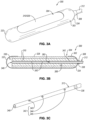
- FIGS. 3A and 3B are isometric and cross-sectional views of a fluid collection assembly 300.
- the fluid collection assembly 300 may be the same or substantially to any of the fluid collection assemblies disclosed herein.
- the fluid collection assembly 300 may include a fluid impermeable barrier 302 defining an opening 304, a chamber 306, and a fluid outlet 308.
- the fluid impermeable barrier 300 also includes at least one porous material 310 disposed in the chamber 306 and at least one conduit 312 secured to the fluid outlet 308.
- the fluid collection assembly 300 exhibits a generally cylindrical shape.
- the elongated shape of the fluid collection assembly 300 may allow the fluid collection assembly 300 to exhibit a size and shape that fits in the gluteal cleft between the legs of an individual, especially a non-thin individual.
- the elongated shape of the fluid collection assembly 300 allows the opening 304 to exhibit an elongated shape wherein a length of the opening 304 is significantly greater than the width of the opening 304.
- the opening 304 may have an elongated shape because the space between the legs of a female is relatively small when the legs of the female are closed, thereby only permitting the flow of the bodily fluids along a path that corresponds to the elongated shape of the opening 304 ( e . g ., longitudinally extending opening). Further, the curved outermost surface of the fluid collection assembly 300, and more particularly the curved outermost surface 328 of the porous material 310, will press against the labia folds.
- the fluid collection assembly 300 includes a first end 332 and a second end 334 spaced from the first end 332.
- the first end 332 may define a substantially unoccupied fluid reservoir 336.
- the second end 334 may define the fluid outlet 308.
- the conduit 312 may include an outlet portion 338 disposed in the fluid outlet 308.
- the outlet portion 338 may secure the conduit 312 to the fluid outlet 308 via press fitting, an adhesive, ultrasonic welding, or any other suitable attachment technique.
- the conduit 312 may extend longitudinally from the fluid outlet 308, behind at least partially of the porous material 310 ( e.g ., through a central region of the porous material 310), to the fluid reservoir 336.
- the conduit 312 may include an open terminal end 340 that is positioned adjacent to or within the fluid reservoir 336.
- the open terminal end 340 is configured to remove bodily fluids that are present in the fluid reservoir 336, for example, when a suction force is applied to the conduit 312.
- the open terminal end 340 of the conduit 312 may substantially only remove bodily fluids when the bodily fluids are present in the fluid reservoir 336 in sufficient quantity that the bodily fluids contact the open terminal end 340.
- solely relying on the open terminal end 340 to remove bodily fluids may delay removal of the bodily fluids from the chamber 306 since the bodily fluids must first flow into the fluid reservoir 336 in sufficient quantity to be removed and at least some of the bodily fluids may not be removed from the chamber 306 when the quantity of bodily fluids in the fluid reservoir 336 are insufficient to contact the open terminal end 340, both of which may increase the likelihood that the fluid collection assembly 300 leaks.
- the one or more leak prevention features of the fluid collection assembly 300 includes at least one conduit inlet 342 formed in the conduit 312 (e . g ., the conduit 312 includes a plurality of inlets, namely the open terminal end 340 and the at least one conduit inlet 342).
- the conduit inlet 342 includes an inlet formed in the conduit 312 between the outlet portion 338 and the open terminal end 340 that is in fluid communication with an interior 362 ( e . g ., passageway) of the conduit 312.
- the conduit inlet 342 refer to inlets formed in the conduit 312 that are distinct from the open terminal end 340.
- the conduit inlet 342 allows the conduit 312 to remove bodily fluids from the chamber 306 that are spaced from the fluid reservoir 336 in addition to the bodily fluids that are present in the fluid reservoir 336.
- the open terminal end 340 of the conduit 312 may be omitted and the conduit 312 may only include one or more conduit inlets 342.
- the conduit inlet 342 may include a one-way valve (not shown).
- the one-way valve may be configured to allow the bodily fluids to flow from an exterior ( e . g ., the chamber 306) of the conduit 312 into an interior 362 of the conduit 312 and restrict the flow of the bodily fluids from the interior 362 to the exterior of the conduit 312.
- the one-way valve may prevent bodily fluids that are received upstream from one of the conduit inlet 342 from exiting the conduit 312. Allowing the bodily fluids to exit the conduit 312 at a location downstream from where the bodily fluids were received may increase the likelihood that the fluid collection assembly 300 leaks.
- the one-way valve may include any suitable one-way valve.
- the one-way valve is a flap formed in the interior 362 of the conduit 312.
- the flap may be configured to open when the flow of the bodily fluids is from the exterior to the interior 362 of the conduit 312 and close when the flow of the bodily fluids is from the interior 362 to the exterior of the conduit 312.
- the one-way valve includes a ball valve that substantially only permits the bodily fluids to flow from the exterior to the interior 362 of the conduit 312.
- the conduit inlets 342 may also allow the fluid collection assembly 300 to be used when the individual using the fluid collection assembly 300 is in different positions.
- the fluid reservoir 336 is the gravimetrically lowest point of the chamber 306.
- gravity pulls the bodily fluids towards the fluid reservoir 336 in addition to the permeability of the porous material 310 and the suction force.
- switching the position of the individual from the lying position to another position e . g ., sitting or standing position
- the conduit 312 may include one or more of the open terminal end 340 that is configured to receive bodily fluids when the individual is lying down, at least one first conduit inlet 343 that is configured to receive bodily fluids when the individual is sitting down, at least one second conduit inlet 344 that is configured to receive bodily fluids when the individual is standing up, and at least one third conduit inlet 345 that is configured to receive bodily fluids when the individual is leaning forward.
- the second conduit inlet 344 may be spaced from the open terminal end 340 by about 40% to about 60% (e.g., about 40% to about 50%, about 45% to about 55%, about 50% to about 60%, or about 50%) of the length of the conduit 312 which may position the second conduit inlet 344 at or near the gravimetrically lowest point of the chamber 306 when the individual is standing.
- the third conduit inlet 345 may be spaced from the open terminal end 340 by about 60% to about 99% ( e.g ., about 60% to about 80%, about 70% to about 90%, about 80% to about 99%) of the length of the conduit 312 which may position the third conduit inlet 345 at or near the gravimetrically lowest point of the chamber 306 when the individual is leaning forward.
- first, second, and third conduit inlets 343, 344, 345 may vary depending on the size and placement of the fluid collection assembly 300 but the values provided above are accurate for most embodiments where the fluid collection assembly 300 exhibits an elongated shape.
- the conduit 312 may include valve (not shown) that closes at least one of the inlets of the conduit 312 (e . g ., the open terminal end 340 or one of the conduit inlets 342) when the inlet is not at or near the gravimetrically low point of the chamber 306.
- the valve may close the inlet when the inlet is not at or near the gravimetrically low point of the chamber 306 since the inlet is more likely to pull air into the conduit 312 when the inlet is not at or near the gravimetrically low point of the chamber 306 and decreases the overall efficiency of the conduit 312.
- the valve may include a ball valve that is configured to close an inlet of the conduit 312 when the inlet is not at or near the gravimetrically low point of the chamber 306 and open the inlet of the conduit 312 when the inlet is at or near the gravimetrically low point of the chamber 306.
- a ball of the ball valve may press against the inlet of the conduit 312 when the inlet is not at or near the gravimetrically low point of the chamber 306 and the ball of move into a recess thereby opening the inlet when the inlet is at or near the gravimetrically low point of the chamber 306.
- the open terminal end 340a and the conduit inlets 342a will remove air from the chamber preferentially over bodily fluids.
- the conduit 312a will remove significantly less bodily fluids than if each of the inlets were exposed to the bodily fluids.
- the inlets of the conduit 312a may be configured to exhibit different sizes ( e . g ., diameter) depending on the likelihood that the inlets will remove bodily fluids or air at any given time.
- the open terminal end 340a may exhibit the largest opening ( e .
- FIGS. 3C and 3D exhibit a generally circular shape.
- the conduit inlets may exhibit any suitable shape.
- FIG. 3E is an isometric view of a conduit 312b that may be used in any of the fluid collection assemblies disclosed herein. Except as otherwise disclosed herein, the conduit 312b may be the same or substantially similar to any of the conduits disclosed herein.
- the conduit 312b may include an open terminal end 340b and at least one conduit inlet 342b.
- the conduit inlet 342b in the illustrated embodiment, exhibits a slot-like shape instead of the generally circular shapes illustrated in FIGS. 3C and 3D .
- FIG. 3F is an isometric view of a plurality of conduits that may be used in any of the fluid collection assemblies disclosed herein (e.g., the fluid collection assembly may include the plurality of conduits instead of a single conduits).
- the plurality of conduits are illustrated and discussed as having a first conduit 312c, a second conduit 312d, and a third conduit 312e. However, this is for illustrative purposes only and it is understood that the plurality of conduits may include two conduits or four or more conduits and that the same principles disclosed herein are applicable regardless of the number of conduits.
- each of the first, second, and third conduits 312c, 312d, 312e may be the same or substantially similar to any of the conduits disclosed herein.
- each of the first, second, and third conduits 312c, 312d, 312e may include a first, second, and third outlet portion 338c, 338d, 338e (cross-hatched for illustrative purposes) and a first, second, and third open terminal end 340c, 340d, 340e, respectively.
- At least one of the first, second, or third conduits 312c, 312d, 312e may also include at least one conduit inlet (not shown).
- the first, second, and third conduits 312c, 312d, 312e may each be connected to separate vacuum sources thereby eliminating the need for valves.
- many locations e . g ., hospitals
- the suction control apparatus 348 may include one or more sensors that detect whether the first, second, and/or third conduits 312c, 312d, 312e are removing bodily fluids or air.
- the sensors may include one or more moisture sensors configured to detect the presence of the bodily fluids in the conduit 312, one or more optical sensors configured to detect the presence of the bodily fluids in an at least partially transparent conduit 312, one or more acoustic sensors configured to detect the sound of bodily fluids through the conduit 312, one or more oxygen sensors configured to detect the presence of oxygen ( e . g ., air) in the conduit 312, or any other suitable sensor.
- the fluid collection assembly 400 is the same or substantially similar to any of the fluid collection assemblies disclosed herein.
- the fluid collection assembly 400 is illustrated as being substantially similar to the fluid collection assembly 200 and, as such, includes a fluid impermeable barrier 402 defining a chamber 406, at least partially porous material 410 disclosed in the chamber 406, and at least one conduit 412.
- a fluid impermeable barrier 402 defining a chamber 406, at least partially porous material 410 disclosed in the chamber 406, and at least one conduit 412.
- the principles discussed herein are also applicable to the other fluid collection assemblies disclosed herein.
- the fluid collection assembly 400 includes at least one fluid reservoir 436 that is substantially unoccupied.
- the fluid reservoir 436 extends at least partially along the length of the conduit 412.
- the fluid reservoir 436 may be a leak prevention feature since the fluid reservoir 436 may facilitate quick removal of any bodily fluids that are present in the chamber 406.
- the conduit 412 may define a plurality of inlets 414 longitudinally spaced from each other, which allows the conduit 412 to remove bodily fluids from a plurality of different locations in the chamber 406. At least one of the plurality of inlets 414 of the conduit 412 may be adjacent to the fluid reservoir 436.
- the fluid reservoir 436 may allow the bodily fluids to quickly and easily flow to the plurality of inlets 414.
- the fluid reservoir 436 may allow the bodily fluids to accumulate adjacent to at least one of the inlets 414 when the individual is in a sitting position.
- the fluid reservoir 436 may then allow the bodily fluids to quickly and easily flow to another one(s) of the inlets 414 when the individual moves, such as moves from the sitting position to a standing position.
- the fluid reservoir 436 allows for the quick removal of bodily fluids from the chamber 406, even when the individual moves.
- the one or more leak prevention features of any of the fluid collection assemblies disclosed herein may include a leak prevention layer that forms a portion of the porous material.
- the leak prevention layer is configured to encourage flow of the bodily fluids therein in a first direction and discourage flow of the bodily fluids therein in a second direction that is opposite the first direction thereby inhibiting the bodily fluids from leaking from the chamber.
- FIG. 5A is a schematic cross-sectional view of a leak prevention layer 552.
- the leak prevention layer 552 includes a plurality of sheets 554.
- the leak prevention layer 552 may include at least one first sheet 554a and at least one second sheet 554b positioned downstream from the first sheet 554a.
- downstream is the direction that the leak prevention layer 552 encourages the bodily fluids to flow.
- the downstream direction extends from the first sheet 554a towards the second sheet 554b and, during operation, generally extends from the urethral opening of the individual towards the chamber.
- the leak prevention layer 552 may also include one or more additional sheets positioned downstream from the second sheet 554b, such as the at least one third sheet 554c illustrated in FIG. 5A .
- Each of the sheets 554 define a plurality of void spaces 556 extending therethrough.
- the void spaces 556 may include apertures (as shown), a plurality of interconnected pores, etc.
- the plurality of void spaces 556 are configured to control the flow rate of the bodily fluids flowing therethrough.
- the void spaces 556 are configured such that the flow rate of the bodily fluids increases the further downstream the bodily fluids flow ( e . g ., with further distance from the first sheet 554a and/or the urethral opening) which encourages the bodily fluids to flow in the downstream direction.
- the void spaces 556 also discourage the bodily fluids flowing in an upstream direction ( e .
- the leak prevention layer 552 inhibits leaks because any bodily fluids that are present in the second sheet 554b are more likely to flow to and through the third sheet 554c than the first sheet 554a (ignoring suction forces, wicking and capillary actions, and gravity).
- any bodily fluids that are present in the second sheet 554b are more likely to flow to and through the third sheet 554c than the first sheet 554a since more of the bodily fluids may flow through the third sheet 554c during a given time period than the first sheet 554a.
- the rate at which the bodily fluids flow through each of the sheets 554 may depend on the collective cross-sectional area of the void spaces 556 (e . g ., the sum of the cross-sectional area of each of the void spaces 556 along a selected plane).
- the collective cross-sectional area of the void spaces 556 increases the flow rate of the bodily fluids and decreasing the collective cross-sectional area of the void spaces 556 decreases the flow rate of the bodily fluids.
- the collective cross-sectional area of the void spaces 556 generally increases in the downstream direction.
- the collective cross-sectional area of the void spaces 556 depends on the number density of void spaces 556 that are formed in each of the sheets 554 in a selected area.
- the number density of void spaces 556 formed in each sheet 554 generally increases in the downstream direction.
- the first sheet 554a may exhibit a first number density of the void spaces 556
- the second sheet 554b may exhibit a second number density of void spaces 556 that is greater than the first number density
- the third sheet 554c may exhibit a third number density of void spaces 556 that is greater than the second number density.
- the collective cross-sectional area of the void spaces 556 depends on the average cross-sectional area of each of the void spaces 556 that are formed in each of the sheets 554 in a selected area. In such an embodiment, the average cross-sectional area of each of the void spaces 556 formed in each sheet 554 generally increases in the downstream direction.
- each of the void spaces 556 of the first sheet 554a may exhibit a first average cross-sectional area
- each of the void spaces 556 of the second sheet 554b may exhibit a second average cross-sectional area that is greater than the first average cross-sectional area
- each of the void spaces 556 of the third sheet 554c may exhibit a third average cross-sectional area that is greater than the second average cross-sectional area.
- each of the sheets 554 are not attached to each other or only selected portions of the sheets 554 are attached to each other.
- passageways 558 are allowed to form between adjacent sheets 554.
- the void spaces 556 of adjacent sheets 554 may not align with each other.
- the bodily fluid may be unable to flow through void spaces 556 that are not aligned with each other, especially if the sheets 554 are formed from a fluid impermeable material or a material exhibiting limited fluid permeability.
- the leak prevention layer 552 may be unable to encourage the bodily fluids to flow in the downstream direction.
- the leak prevention layer 552 may be formed from wicking materials ( e . g ., at least one hydrophobic material).
- the leak prevention layer 552 may be formed from any of the same materials as the fluid permeable membranes or the fluid permeable supports disclosed herein.
- the leak prevention layer 552 may be formed from non-wicking material, such as at least one non-polyester polymer, at least one hydrophilic material, or any other absorbent or adsorbent material.
- FIG. 5B is a schematic partial cross-sectional view of a portion of a fluid collection assembly 500a that includes at least one leak prevention layer 552a. Except as otherwise disclosed herein, the fluid collection assembly 500a is the same or substantially similar to any of the fluid collection assemblies disclosed herein.
- the fluid collection assembly 500a may include a fluid impermeable barrier 502a defining an opening 504a and a chamber 506a.
- the fluid collection assembly 500a may also include at least one porous material 510a.
- the porous material 510b includes the leak prevention layer 552b, a fluid permeable membrane 522, and at least one additional layer 560b.
- the additional layer 560b may include, for example, a fluid permeable support, or an absorption layer.
- the fluid permeable membrane 522 may be selected to be softer or otherwise more comfortable when contacting the vulva of an individual than the leak prevention layer 552b. As such, the fluid permeable membrane 522 extends at least partially across the opening 504b thereby preventing the leak prevention layer 552b from contacting the vulva. Instead, the fluid permeable membrane 522 may contact or otherwise be positioned proximate to the a urethral opening of the individual during operation.
- the leak prevention layer 552 may be positioned between the fluid permeable membrane 522 and the additional layer 560b thereby allowing the additional layer 560b to be positioned downstream from and support the leak prevention layer 552b.
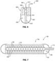
- FIG. 6 is a schematic partial cross-sectional view of a portion of the fluid collection assembly 600. Except as otherwise disclosed herein, the fluid collection assembly 600 is the same or substantially similar to any of the fluid collection assemblies disclosed herein.
- the fluid collection assembly 600 may include a fluid impermeable barrier 602 defining an opening 604 and a chamber 606.
- the fluid collection assembly 600 further includes a porous material 610 and a conduit 612 disposed in the chamber 606.
- the fluid collection assembly 600 also includes a fluid reservoir 636 that is substantially unoccupied.
- the conduit 612 includes at least one inlet 614 ( e . g ., open terminal end or conduit inlet) that is adjacent to or positioned in the fluid reservoir 636.
- the conduit 612 may not extend all the way into the fluid reservoir 636 to prevent the fluid impermeable barrier 602 from being suctioned to and completely obstructing the inlet 614.
- the conduit 612 is only able to remove bodily fluids that accumulate in the fluid reservoir 636 once the bodily fluids contact or are adjacent to the inlet 614, otherwise the inlet 614 merely pull air into the conduit 612.
- the conduit 612 may only remove bodily fluids from the fluid reservoir 636 when a certain quantity of bodily fluids are present in the fluid reservoir 636.
- bodily fluids may remain in the fluid reservoir 636 long after the individual discharges the bodily fluids. The delay in removing the bodily fluids and leaving some bodily fluids in the fluid reservoir 636 may increase the likelihood that the fluid collection assembly 600 leaks.
- the fluid collection assembly 600 may include a leak prevention feature that is configured to minimize any delay in removing the bodily fluids and minimize the amount of bodily fluids that remain the fluid reservoir 636.
- the leak prevention feature may include an additional porous material 616 that is partially disposed in at least a portion of an interior 662 of conduit 612.
- the additional porous material 616 also extends from the inlet 614 into the fluid reservoir 636, such as from the inlet 614 to the fluid impermeable barrier 602. During operation, the bodily fluids that enter the fluid reservoir 636 contact the addition porous material 616 before the bodily fluids contact or are adjacent to the inlet 614 of the conduit 612.
- the additional porous material 616 pulls the bodily fluids into the interior 662 of the conduit 612 via wicking, capillary action, or absorption.
- the conduit 612 may remove the bodily fluids that are pulled into the interior 662 of the conduit 612.
- the additional porous material 616 may decrease the delay between the bodily fluids entering the fluid reservoir and removing the bodily fluids from the fluid reservoir 636.
- the additional porous material 616 may continue to pull the bodily fluids from the fluid reservoir 636 even when the individual ceases to discharge bodily fluids into the chamber 606.
- the additional porous material 616 may remove the bodily fluids from the fluid reservoir 636 until all or substantially all of the bodily fluids are removed from the fluid reservoir 636.
- the additional porous material 616 decreases the likelihood that the fluid collection assembly 600 leaks the bodily fluids.
- the one or more leak prevention features of any of the fluid collection assemblies disclosed herein include one or more features that are configured to allow the fluid collection assemblies to conform to a shape of a vulva and a region about the vulva.
- the shape, size, and topography of the vulva and the region about the vulva may vary. These variations may cause gaps to form between the fluid collection assembly and the vulva and the region about the vulva and bodily fluids may leak through these gaps.
- the leak prevention features may be configured to cause the fluid collection assembly to better conform to the shape, size, and topography of the vulva and the region about the vulva to eliminate or at least minimize any gaps between the fluid collection assembly and the vulva and the region about the vulva. For example, FIG.
- FIG. 7 is a schematic cross-sectional view of a fluid collection assembly 700 that is configured to conform to the vulva and the region about the vulva. Except as otherwise disclosed herein, the fluid collection assembly 700 may be the same or substantially similar to any of the fluid collection assemblies disclosed herein.
- the fluid collection assembly 700 may include a fluid impermeable barrier 702 defining an opening 704 and a chamber 706.
- the fluid collection assembly 700 may also include at least one porous material 710 and at least one conduit 712 disposed in the chamber 706.
- the conduit 712 exhibits a "crinkle" structure.
- the conduit 712 may include one or more peaks 764 (e . g ., a plurality of circumferentially extending peaks 764 or single helically extending peak 764).
- the conduit 712 may also include one or more valleys 766 ( e.g ., a plurality of circumferentially extending valleys 766 or a single helically extending valley 766) disposed between portions of the peaks 764 spaced apart along a longitudinal direction of the conduit 712.
- the conduit 712 may be configured to be bent.
- the peaks 764 and valleys 766 may allow the conduit 712 to more freely bend when an external force is applied thereto and to maintain the bent shape after the external force is removed.
- the bent shape of the conduit 712 also causes the rest of the fluid collection assembly 700 to bend.
- the conduit 712 may allow the fluid collection assembly 700 to be conformed to a shape that generally corresponds to the shape of the vulva and the region about the vulva and to maintain said shape thereby inhibiting or preventing leaks.
- the valleys 766 may remain substantially unoccupied.
- the porous material 710 may not extend into the valleys 766 which may prevent the porous material 710 from inhibiting the conduit 712 from bending or prevent the conduit 712 from maintaining the shape thereof after the external force is removed.
- configuring the porous material 710 to not extend into the valleys 766 may allow the porous material 710 to be formed using an extruding process instead of other more complicated processes.
- the valleys 766 can be occupied by the porous material 710.
- shape memory is used to describe some of the “shape memory materials” herein, it should be understood that, in some examples, the material modified by the term “shape memory” may not necessarily need to return to a preselected shape upon application of a stimuli, as understood as the classical definition of the "shape memory material.” Rather, at least some of the shape memory materials herein may simply hold a selected shape when bent, set, or cured into a specific shape and/or when cooled in a specific shape, regardless of the stimuli applied thereto after. The shape memory materials may be returned to the original shape or changed to a new shape by application of stimuli.
- a metal wire bent to a first shape may be utilized as the shape memory material, whereinafter the metal wire may be modified to a second shape via physical force applied thereto or via heating.
- the shape memory material 872 may include a shape memory alloy (e . g ., nitinol), a shape memory polymer, copper, aluminum, steel, iron, or any other suitable material that is bendable and maintains its shape after being bent.
- the shape memory material 872 is a wire exhibiting a general zig-zag shape.
- the generally zig-zag shape of the shape memory material 872 allows the shape memory material 872 to change the shape of a greater portion of fluid collection assembly 800 than if the shape memory material 872 was a generally straight or curved wire while exhibiting a lesser weight than if the shape memory material 872 was a plate.
- Some conventional fluid collection assemblies include a conduit exhibiting an outer diameter that is greater than about 1 cm that extends through substantially all of the fluid collection assembly. Such conventional fluid collection assemblies may exhibit a fluid reservoir that may hold about 10 milliliters ("ml") to about 14 ml of bodily fluids and may hold about 24 ml of bodily fluids in the chamber before leaking. Some individuals may discharge more than 24 ml of bodily fluids in the first second of urination which may cause the fluid collection assembly to leak, especially if there is any delay in removing the bodily fluids from the chamber.
- ml milliliters
- the diameter of the conduit may be decreased without decreasing the amount of bodily fluids that are removed from the chamber thereby increasing the amount of bodily fluids that may be held in the chamber.
- the one or more leak prevention features of any of the fluid collection assemblies disclosed herein may include using a conduit exhibiting a diameter that is about 5 mm to about 9 mm, such as in ranges of about 5 mm to about 6 mm, about 5.5 mm to about 6.5 mm, about 6 mm to about 7 mm, about 6.5 mm to about 7.5 mm, about 7 mm to about 8 mm, about 7.5 mm to about 8.5 mm, or about 8 mm to about 9 mm.
- the one or more leak prevention features used in any of the fluid collection assemblies disclosed herein may include pre-moistening the at least one porous material before the fluid collection assemblies receive bodily fluids.
- Pre-moistening the porous material may include moistening the porous material with a non-bodily fluid, such as water, saline, or another suitable liquid.
- Pre-moistening the porous material may improve flow of the bodily fluids through the porous material.
- the flow of the bodily fluids through a dry porous material may be slower than the flow of the bodily fluids through a moistened porous material ( e . g ., a pre-moistened porous material or a previously used porous material).
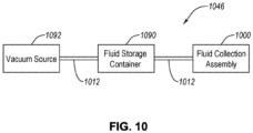
- FIG. 10 is a block diagram of a system 1046 for fluid collection, according to an embodiment.
- the system 1046 includes a fluid collection assembly 1000, a fluid storage container 1090, and a vacuum source 1092.
- the fluid collection assembly 1000, the fluid storage container 1090, and the vacuum source 1092 may be fluidly coupled to each other via one or more conduits 112.
- fluid collection assembly 1000 may be operably coupled to one or more of the fluid storage container 1090 or the vacuum source 1092 via the conduit 1012.
- the bodily fluids collected in the fluid collection assembly 1000 may be removed from the fluid collection assembly 1000 via the conduit 1012 which protrudes into the fluid collection assembly 1000.
- an inlet of the conduit 1012 may extend into the fluid collection assembly 1000, such as to a reservoir therein.
- the outlet of the conduit 1012 may extend into the fluid collection assembly 1000 or the vacuum source 1092. Suction force may be introduced into the chamber of the fluid collection assembly 1000 via the inlet of the conduit 1012 responsive to suction ( e . g ., vacuum) force applied at the outlet of the conduit 1012.
- suction e . g ., vacuum
- the fluid collection assembly 1000 may include a fluid permeable membrane disposed within the fluid impermeable barrier.
- the fluid collection assembly 1000 may include at least one porous material disposed in the chamber such as one or more of a fluid permeable support and a fluid permeable membrane.
- the fluid collection assembly 1000 includes the shape memory material on or incorporated in one or more components thereof.
- the shape memory material is sized, shaped, and positioned to retain a selected geometric configuration as disclosed herein.
- the conduit 1012 may extend into the fluid collection assembly 1000 at a first end ( e . g ., proximal) region, through one or more of the fluid impermeable barrier, fluid permeable membrane, or the fluid permeable support to a second end ( e .
- the conduit 1012 includes an inlet and an outlet, the outlet being fluidly coupled to the fluid storage container and the inlet being positioned in a portion of the chamber selected to be at a gravimetrically low point of the fluid collection assembly 1000 when worn.
- the fluid storage container 1090 is sized and shaped to retain the bodily fluids therein.
- the fluid storage container 1090 may include a bag ( e . g ., drainage bag), a bottle or cup ( e . g ., collection jar), or any other enclosed container for storing bodily fluids such as urine.
- the conduit 1012 may extend from the fluid collection assembly 1000 and attach to the fluid storage container 1090 at a first point therein.
- An additional conduit 1012 may attach to the fluid storage container 1090 at a second point thereon and may extend and attach to the vacuum source 1092. Accordingly, a vacuum ( e . g ., suction) may be drawn through fluid collection assembly 1000 via the fluid storage container 1090.
- the bodily fluids, such as urine may be drained from the fluid collection assembly 1000 using the vacuum source 1092.
Landscapes
- Health & Medical Sciences (AREA)
- Vascular Medicine (AREA)
- Animal Behavior & Ethology (AREA)
- Nursing (AREA)
- Orthopedic Medicine & Surgery (AREA)
- Engineering & Computer Science (AREA)
- Biomedical Technology (AREA)
- Heart & Thoracic Surgery (AREA)
- Veterinary Medicine (AREA)
- Epidemiology (AREA)
- General Health & Medical Sciences (AREA)
- Life Sciences & Earth Sciences (AREA)
- Public Health (AREA)
- Reproductive Health (AREA)
- Orthopedics, Nursing, And Contraception (AREA)
- Absorbent Articles And Supports Therefor (AREA)
- External Artificial Organs (AREA)
- Sampling And Sample Adjustment (AREA)
Description
- A person or animal may have limited or impaired mobility such that typical urination processes are challenging or impossible. For example, a person may experience or have a disability that impairs mobility. A person may have restricted travel conditions such as those experienced by pilots, drivers, and workers in hazardous areas. Additionally, sometimes bodily fluids collection is needed for monitoring purposes or clinical testing.
- Urinary catheters, such as a Foley catheter, can be used to address some of these circumstances, such as incontinence. Unfortunately, urinary catheters can be uncomfortable, painful, and can lead to complications, such as infections. Additionally, bed pans, which are receptacles used for the toileting of bedridden patients are sometimes used. However, bedpans can be prone to discomfort, spills, and other hygiene issues.
-
JP 2004-267530 A -
US 4,747,166 discloses an absorptive pad in which is a tube with a closed end, a multiplicity of through holes in its cylindrical wall. The tube is connected to a vacuum pump to aspirate urine out of the pad, through the holes and into a urine collection vessel. - The invention is defined in the independent claim below. The dependent claims are directed to optional features and preferred embodiments. The pre-characterizing part of claim 1 is based on the disclosure of Applicant's
WO 2019/212950A1 . In an embodiment, a fluid collection assembly is disclosed. The fluid collection assembly includes a fluid impermeable barrier defining, at least one opening, a chamber in fluid communication with the at least one opening, and at least one fluid outlet. The fluid collection assembly also includes at least one porous material disposed in the chamber. Further, the fluid collection assembly includes at least one conduit attached to the at least one fluid outlet. The fluid collection assembly additionally includes one or more leak prevention features configured to at least inhibit bodily fluids leaking from the chamber - Features from any of the disclosed embodiments may be used in combination with one another, without limitation. In addition, other features and advantages of the present disclosure will become apparent to those of ordinary skill in the art through consideration of the following detailed description and the accompanying drawings.
- The drawings illustrate several embodiments of the present disclosure, wherein identical reference numerals refer to identical or similar elements or features in different views or embodiments shown in the drawings.
- The drawings illustrate several embodiments of the present disclosure, wherein identical reference numerals refer to identical or similar elements or features in different views or embodiments shown in the drawings.
-
FIG. 1A is a top plan view of a fluid collection assembly that includes one or more leak prevention features. -
FIG. 1B is a cross-sectional view of the fluid collection assembly taken alongline 1B-1B shown inFIG. 1A . -
FIG. 2A is a top plan view of a fluid collection assembly. -
FIG. 2B is a cross-sectional view of the fluid impermeable barrier taken alongling 2B-2B. -
FIGS. 3A and 3B are isometric and cross-sectional views of a fluid collection assembly, respectively. -
FIG. 3C is an isometric view of the conduit illustrating how the at least one conduit inlet may facilitate removing bodily fluids from the chamber when the individual using the fluid collection assembly is in a position other than lying down. -
FIG. 3D is an isometric view of a conduit that may be used in any of the fluid collection assemblies disclosed herein. -
FIG. 3E is an isometric view of a conduit that may be used in any of the fluid collection assemblies disclosed herein. -
FIG. 3F is an isometric view of a plurality of conduits that may be used in any of the fluid collection assemblies disclosed herein. -
FIG. 3G is an isometric view of a system that includes the first, second, and third conduits and a suction control apparatus. -
FIG. 4 is cross-sectional view of a fluid collection assembly that includes a fluid reservoir extending along the conduit. -
FIG. 5A is a schematic cross-sectional view of a leak prevention layer. -
FIG. 5B is a schematic partial cross-sectional view of a portion of a fluid collection assembly that includes at least one leak prevention layer. -
FIG. 5C is a schematic partial cross-sectional view of a portion of a fluid collection assembly that includes at least one leak prevention layer. -
FIG. 6 is a schematic partial cross-sectional view of a portion of the fluid collection assembly. -
FIG. 7 is a schematic cross-sectional view of a fluid collection assembly that is configured to conform to the vulva and the region about the vulva. -
FIG. 8 is a bottom plan view of a fluid collection assembly that is configured to conform to the vulva and the region about the vulva. - FIG. 9A is deleted.
- FIG. 9B is deleted.
-
FIG. 10 is a block diagram of a system for fluid collection. - The disclosure below is of bodily fluids collection assemblies that include one or more leak prevention features along with systems including and methods of using such bodily fluids collection assemblies. An example fluid collection assembly includes a fluid impermeable barrier defining at least one opening, a chamber in fluid communication with the at least one opening, and at least one fluid outlet. The fluid collection assembly also includes at least one porous material (e.g., at least one wicking material) disposed in the chamber. The fluid collection assembly also includes at least one conduit attached to the fluid outlet. During operation, the fluid collection assembly may receive bodily fluids (e.g., urine) from an individual (e.g., human) through the opening and into the chamber. The porous material may receive at least some of the bodily fluids that enter the chamber. A suction applied from the conduit to the chamber may direct the bodily fluids in chamber towards the conduit. The conduit may then remove the bodily fluids from the chamber.
- The fluid collection assembly includes one or more leak prevention features. The leak prevention features decrease the likelihood that the fluid collection assembly leaks compared to a substantially similar fluid collection assembly that does not include the leak prevention features. For example, the bodily fluids may leak from the fluid collection assembly when the bodily fluids flow out of the chamber through the opening or the bodily fluids fail to enter the chamber. The leaked bodily fluids may cause the individual embarrassment and an create unsanitary environment. The bodily fluids may leak from the fluid collection assembly for a variety of reasons, examples of which include movement of the individual, oversaturation of the porous material, and/or the opening of the fluid collection assembly becoming spaced from the individual. The leak prevention features of the fluid collection assembly are configured to minimize or prevent at least some of the reasons that cause the fluid collection assembly to leak.
-
FIG. 1A is a top plan view of afluid collection assembly 100 that includes one or more leak prevention features.FIG. 1B is a cross-sectional view of thefluid collection assembly 100 taken alongline 1B-1B shown inFIG. 1A . Thefluid collection assembly 100 includes a fluidimpermeable barrier 102. The fluidimpermeable barrier 102 defines at least oneopening 104 configured to receive bodily fluids from an individual. The fluidimpermeable barrier 102 also defines achamber 106 that is in fluid communication with theopening 104 and at least onefluid outlet 108. Thefluid collection assembly 100 also include at least one porous material 110 disposed in thechamber 106 and at least oneconduit 112 attached to thefluid outlet 108. Thefluid collection assembly 100 also include one or more leak prevention features. - The leak prevention features of the
fluid collection assembly 100 can include forming thefluid collection assembly 100 to exhibit a generally non-cylindrical shape. For example, some conventional fluid collection assemblies exhibit a generally cylindrical shape (e.g., bent generally cylindrical shape). Generally, the conventional fluid collection assemblies exhibiting the generally cylindrical shape rely on the thighs of the individual contacting the sides of the conventional fluid collection assembly to maintain the conventional fluid collection assembly against the vulva. However, the thighs of thinner individuals may be unable to contact the sides of the conventional fluid collection assembly and/or separating the legs of the individual (e.g., for comfort or movement) may cause the thighs to cease contacting the sides of the conventional fluid collection assembly. When the thighs of the individual do not contact the sides of the conventional fluid collection assembly, at least a portion of the conventional fluid collection assembly may move away from the individual thereby creating a passageway through which bodily fluids may flow without entering the chamber of the conventional fluid collection assembly. As such, in the illustrated device, thefluid collection assembly 100 exhibits a generally disk-like shape. The generally disk-like shape of thefluid collection assembly 100 has the technical effect of allowing thefluid collection assembly 100 to contact the thighs of the individual even when the individual is thin or is separating the thighs thereof. - The generally disk-like shape of the
fluid collection assembly 100 allows thefluid collection assembly 100 to be relatively flat. In particular, the generally disk-like shape of thefluid collection assembly 100 allows theopening 104 and the portion of the porous material 110 adjacent to theopening 104 to be generally flat. The generally flat shape of thefluid collection assembly 100 allows thefluid collection assembly 100 to exhibit a relatively small thickness relative to conventional fluid collection assemblies. The thickness of thefluid collection assembly 100 is measured from anouter surface 120 of a portion of the fluidimpermeable barrier 102 defining theopening 104 to an opposing portion of theouter surface 120 of the fluidimpermeable barrier 102 in a direction that is perpendicular to a width W and length L of theopening 104. For example, thefluid collection assembly 100 may exhibit a thickness that is about 10 mm or less, about 7.5 mm or less, about 5 mm or less, or in ranges of about 2.5 mm to about 7.5 mm or about 5 mm to about 10 mm. Such thickness may make using thefluid collection assembly 100 more comfortable than conventional fluid collection assemblies which, for example, may exhibit a thickness greater than about 2 cm. It is noted that, in some embodiments, thefluid collection assembly 100 may exhibit a thickness that is greater than about 1 cm, such as at least about 2 cm or at least about 3 cm. The relatively flat shape of thefluid collection assembly 100 may also have the technical effect of allowing thefluid collection assembly 100 to collect bodily fluids from orifices other than a urethral opening, such as from a wound or sacral drainage. It is noted that other non-cylindrically shaped fluid collection assemblies disclosed herein other than the generally disk-like shaped fluid collection assembly 100 (e.g., thefluid collection assembly 200 ofFIGS. 2A-2B ) may also exhibit the relatively flat shape and the relatively small thickness. - The generally disk-like shape of the
fluid collection assembly 100 allows theopening 104 to exhibit a larger width W than conventional fluid collection assemblies. For example, conventional fluid collection assemblies may exhibiting an opening exhibiting a length (e.g., maximum dimension of the opening) that is significantly greater than a width (e.g., a dimension of the opening that is measured perpendicular to the length) of the opening, such as the length of the opening being more than 2.5 times greater than the width. However, the generally disk-like shape of the fluid collection assembly 100 allows the opening 104 to exhibit a width W that is 50% (i.e., half of) to 100% (i.e., equal to) the length L. For example, the width W may be about 50% to about 70%, about 60% to about 80%, about 70% to about 90%, or about 80% to about 100% of the length L. The increased width W of the opening 104 relative to the length L may allow the fluid collection assembly 100 to receive more bodily fluid (i.e., prevent leaks) that flow in a directly that is generally parallel (e.g., ±30°) to the width W compared to convention fluid collection assemblies while receiving the same or substantially the same amount of bodily fluids that flow in a direction that is generally parallel to the length L. The increased width W of the opening 104 relative to the length L may also allow the fluid collection assembly 100 to accommodate larger displacements (e.g., caused by the individual moving) in a direction that is generally parallel to the width W without leaking than conventional fluid collection assemblies while being able to accommodate the same or substantially same displacements in a direction that is generally parallel to the length L. In other words, the larger width W of the opening 104 relative to the length L of the opening 104 is another leak prevention feature of the fluid collection assembly 100. - The generally flat shape of the
fluid collection assembly 100 and/or the relatively large width W of theopening 104 relative to the length L of theopening 104 allows thefluid collection assembly 100 to be secured to the individual by merely resting thefluid collection assembly 100 on the individual (e.g., resting thefluid collection assembly 100 adjacent to the urethral opening). The generally flat shape of thefluid collection assembly 100 and/or the relatively large width W of theopening 104 relative to the length L of theopening 104 allows thefluid collection assembly 100 to be secured to the individual using an adhesive, straps, or underwear (e.g., the underwear includes a pocket that receives thefluid collection assembly 100 and/or the underwear is configured to press thefluid collection assembly 100 against the urethral opening). - As will be discussed in more detail below, the
fluid collection assembly 100 may exhibit a shape that is not a generally disk-like shape. For example, thefluid collection assembly 100 may exhibit a generally semi-cylindrical shape (FIGS 2A and 2B ), a generally flat elongated shape, a generally cylindrical shape (FIG. 3A ), or any other suitable shape. - Referring to
FIG. 1B , the one or more leak prevention features includes occupying substantially all of thechamber 106 with the porous material 110. For example, some fluid collection assemblies (e.g., thefluid collection assemblies FIGS. 3B ,4 ,6 and 7 ) include substantially unoccupied fluid reservoir in which bodily fluids may pool before the bodily fluids are removed from the chamber. During normal operation, gravity, the suction force, and fluid dynamics (capillary action and wicking) pulls the bodily fluids from the opening towards these fluid reservoirs. However, movement of the individual using these fluid collection assemblies may cause the bodily fluids pooled in the fluid reservoirs to shift (e.g., splash) into the porous materials in sufficient quantities that gravity, the suction force, and fluid dynamics cannot prevent at least some of the bodily fluids from exiting the chamber through the opening. However, referring back to thefluid collection assembly 100, substantially occupying all of thechamber 106 with the porous material 110 prevents the bodily fluids from pooling in a single location. Instead, the bodily fluids are distributed through thechamber 106. As such, no single location in thechamber 106 may include a sufficient quantity of bodily fluids that, when the individual using thefluid collection assembly 100 moves, gravity, the suction force, and fluid dynamics does not pull the bodily fluids towards at least oneinlet 114 of theconduit 112. In other words, substantially occupying thechamber 106 with the porous material 110 may decrease the likelihood that thefluid collection assembly 100 leaks fluids when the individual moves. Further, substantially occupying thechamber 106 allows theconduit 112 to remove the bodily fluids regardless of the quantity of bodily fluids that are present in thechamber 106, unlike the fluid reservoirs that must receive a certain quantity of bodily fluids before theconduit 112 may remove the bodily fluids. As such, the fluid reservoirs may cause a delay between receiving the bodily fluids and removing the bodily fluids which may increase the likelihood of leaks while substantially occupying all of thechamber 106 with the porous material 110 prevents such leaks. - The one or more leak prevention features can include at least one additional
porous material 116 at least partially occupying an interior of theconduit 112. As used herein, the additionalporous material 116 may be integrally formed with at least a portion of the porous material 110 that is disposed in the chamber 106 (e.g., the additionalporous material 116 and at least a portion of the porous material 110 exhibit single piece construction) or the additionalporous material 116 may be distinct from the porous material 110. When theconduit 112 is not at least partially occupied with the additionalporous material 116, theconduit 112 may require a suction force to remove bodily fluids from thechamber 106. In some embodiments, the suction force applied to theconduit 112 is not continuous since the constant air flow may dry the skin and/or the suction force may cause hickeys. As such, the suction force may not be applied to theconduit 112 when discharge of the bodily fluids (e.g., urination) is not expected. However, unexpected bodily fluid discharge may saturate the porous material 110 and cause thefluid collection assembly 100 to leak when a suction force is not applied to theconduit 112 without the additionalporous material 116. However, when theconduit 112 is at least partially occupied by the additionalporous material 116, the additionalporous material 116 may pull the bodily fluids into theconduit 112 via capillary action, absorption, and/or wicking even when a suction force is not applied to theconduit 112. Even though the additionalporous material 116 may be unable to pull the fluid completely through theconduit 112 or may pull the bodily fluids through theconduit 112 more slowly than the suction force, the additionalporous material 116 may increase the quantity of bodily fluids that thefluid collection assembly 100 may receive before the porous material 110 saturates and thefluid collection assembly 100 leaks. - The additional
porous material 116 extends inwardly from theinlet 114 of theconduit 112. The additionalporous material 116 is positioned in theconduit 112 to contact the porous material 110 or such that any gap between the porous material 110 and the additionalporous material 116 is sufficiently small that only a small quantity of bodily fluids is necessary to bridge the gap. The additionalporous material 116 may extend through an entirety of theconduit 112 which allows the additionalporous material 116 to pull the bodily fluids a far distance into theconduit 112, such as through an entirety of theconduit 112. When the additionalporous material 116 only extends inwardly from theinlet 114 for a distance that is less than a length of theconduit 112 extending the additionalporous material 116 only through a portion of theconduit 112 may improve fluid flow in theconduit 112. For example, the additionalporous material 116 may slightly obstruct fluid flow in the portions of theconduit 112. - The one or more leak prevention features may include a plurality of
fluid outlets 108 and at least oneconduit 112 extending from each of thefluid outlets 108. For example, theconduit 112 preferentially removes bodily fluids that are closer to theinlet 114. The plurality offluid outlets 108 and theconduit 112 attached to each of thefluid outlets 108 allows a larger volume of the bodily fluids that are present in thechamber 106 to be preferentially removed from thechamber 106. In other words, the plurality offluid outlets 108 and theconduit 112 decrease the amount of bodily fluids that remain in thechamber 106 thereby decreasing the likelihood that thefluid collection assembly 100 leaks. Further, the plurality ofconduits 112 better distribute any pressure that is applied from thefluid collection assembly 100 to the individual thereby decreasing the likelihood that thefluid collection assembly 100 causes pressure ulcers. Theconduits 112 may also be flat tubes which may make theconduits 112 more comfortable against the skin. - As previously discussed, the fluid
impermeable barrier 102 at least partially defines anopening 104 and a chamber 106 (e.g., interior region). For example, at least oneinner surface 118 of the fluidimpermeable barrier 102 at least partially defines thechamber 106 within thefluid collection assembly 100. The fluidimpermeable barrier 102 temporarily stores the bodily fluids in thechamber 106. The fluidimpermeable barrier 102 may be formed of any suitable fluid impermeable material(s), such as a fluid impermeable polymer (e.g., silicone, polypropylene, polyethylene, polyethylene terephthalate, a polycarbonate, etc.), a metal film, natural rubber, another suitable material, or combinations thereof. As such, the fluidimpermeable barrier 102 substantially prevents the bodily fluids from passing through the fluidimpermeable barrier 102. In an example, the fluidimpermeable barrier 102 may be air permeable and fluid impermeable. In such an example, the fluidimpermeable barrier 102 may be formed of a hydrophobic material that defines a plurality of pores. At least one or more portions of at least anouter surface 120 of the fluidimpermeable barrier 102 may be formed from a soft and/or smooth material, thereby reducing chafing. During use, theouter surface 120 of the fluidimpermeable barrier 102 may contact the wearer. The fluidimpermeable barrier 102 may be sized and shaped to fit in the gluteal cleft between the legs of a female user. - The
opening 104 provides an ingress route for bodily fluids to enter thechamber 106. Theopening 104 may be defined by the fluidimpermeable barrier 102 such as by an inner edge of the fluidimpermeable barrier 102. For example, theopening 104 is formed in and extends through the fluidimpermeable barrier 102, from theouter surface 120 to theinner surface 118, thereby enabling the bodily fluids to enter thechamber 106 from outside of thefluid collection assembly 100. In an embodiment, theopening 104 may be an elongated hole (the length L is more than 50% greater than the width W, as shown inFIG. 3A ) in the fluidimpermeable barrier 102. For example, theopening 104 may be defined as a cut-out in the fluidimpermeable barrier 102. Theopening 104 may be located and shaped to be positioned adjacent to a female urethral opening. - The
fluid collection assembly 100 may be positioned proximate to the female urethral opening and urine may enter thechamber 106 of thefluid collection assembly 100 via theopening 104. Thefluid collection assembly 100 is configured to receive the bodily fluids into thechamber 106 via theopening 104. When in use, theopening 104 may extend from a first location above the urethral opening (e.g., at or near the top of the urethral opening or the pubic hair) to a second location below the urethral opening (e.g., at or near the anus or the vaginal opening). - In some examples, as previously discussed, the fluid
impermeable barrier 102 may define anfluid outlet 108 sized to receive theconduit 112. The at least oneconduit 112 may be disposed in thechamber 106 or otherwise in fluid communication with thechamber 106 via thefluid outlet 108. Thefluid outlet 108 may be sized and shaped to form an at least substantially fluid tight seal against theconduit 112 or the at least one tube thereby substantially preventing the bodily fluids from escaping thechamber 106. - The fluid
impermeable barrier 102 may include markings thereon, such as one or more markings to aid a user in aligning thefluid collection assembly 100 on the wearer. For example, a line on the fluid impermeable barrier 102 (e.g., opposite the opening 104) may allow a healthcare professional to align theopening 104 over the urethral opening of the individual wearing thefluid collection assembly 100. In examples, the markings may include one or more of alignment guide or an orientation indicator, such as a stripe or hashes. Such markings may be positioned to align thefluid collection assembly 100 to one or more anatomical features such as a pubic bone, etc. - As previously discussed, the
fluid collection assembly 100 includes porous material 110 disposed in thechamber 106. The porous material 110 may cover at least a portion (e.g., all) of theopening 104. The porous material 110 is exposed to the environment outside of thechamber 106 through theopening 104. The permeable properties referred to herein may be wicking, capillary action, absorption, diffusion, or other similar properties or processes, and are referred to herein as "permeable" and/or "porous." The porous material 110 may also wick the bodily fluids generally towards an interior of thechamber 106, as discussed in more detail below. The porous material 110 may include one or more of a fluidpermeable membrane 122 or a fluidpermeable support 124. - In an embodiment, at least a portion of the porous material 110 may be a wicking material configured to wick any of the bodily fluids away from the
opening 104, thereby preventing bodily fluids from escaping thechamber 106. The wicking material may not include absorption of the bodily fluids into the wicking material. Put another way, substantially no absorption of the bodily fluids into the wicking material may take place after the wicking material is exposed to the bodily fluids. While no absorption is desired, the term "substantially no absorption" may allow for nominal amounts of absorption of the bodily fluids into the wicking material (e.g., absorbency), such as less than about 30 wt% of the dry weight of the wicking material, less than 20 wt%, less than 10 wt%, less than about 7 wt%, less than about 5 wt%, less than about 3 wt%, less than about 2 wt%, less than about 1 wt%, or less than about 0.5 wt% of the dry weight of the wicking material. In an embodiment, at least a portion of theporous material 100 may include an absorbent or adsorbent material. - The
fluid collection assembly 100 may include the fluidpermeable membrane 122 disposed in thechamber 106. The fluidpermeable membrane 122 may cover at least a portion (e.g., all) of theopening 104. The fluidpermeable membrane 122 may be composed to pull/push the bodily fluids away from theopening 104, thereby preventing the bodily fluids from escaping thechamber 106. - The fluid
permeable membrane 122 may include any material that may be permeable to the bodily fluids. For example, the fluidpermeable membrane 122 may include fabric, such as a gauze (e.g., a silk, linen, or cotton gauze), another soft fabric, or another smooth fabric. Forming the fluidpermeable membrane 122 from gauze, soft fabric, and/or smooth fabric may reduce chafing caused by thefluid collection assembly 100. - The
fluid collection assembly 100 may include the fluidpermeable support 124 disposed in thechamber 106. The fluidpermeable support 124 is configured to support the fluidpermeable membrane 122 since the fluidpermeable membrane 122 may be formed from a relatively foldable, flimsy, or otherwise easily deformable material. For example, the fluidpermeable support 124 may be positioned such that the fluidpermeable membrane 122 is disposed between the fluidpermeable support 124 and the fluidimpermeable barrier 102. As such, the fluidpermeable support 124 may support and maintain the position of the fluidpermeable membrane 122. The fluidpermeable support 124 may include any material that may be permeable to the bodily fluids, such as any of the fluid permeable membrane materials disclosed herein above. For example, the fluid permeable membrane material(s) may be utilized in a more dense or rigid form than in the fluidpermeable membrane 122 when used as the fluidpermeable support 124. The fluidpermeable support 124 may be formed from any fluid permeable material that is less deformable than the fluidpermeable membrane 122. For example, the fluidpermeable support 124 may include a porous polymer (e.g., nylon, polyester, polyurethane, polyethylene, polypropylene, etc.) structure (e.g., spun fibers, such as spun nylong fibers) or an open cell foam. In some examples, the fluidpermeable support 124 may be formed from a natural material, such as cotton, wool, silk, or combinations thereof. In such examples, the material may have a coating to prevent or limit absorption of the bodily fluids into the material, such as a water repellent coating. In some examples, the fluidpermeable support 124 may be formed from fabric, felt, gauze, or combinations thereof. In some examples, the fluidpermeable membrane 122 may be optional. For example, the porous material 110 may include only the fluidpermeable support 124. In some examples, the fluidpermeable support 124 may be optionally omitted from thefluid collection assembly 100. For example, the porous material 110 may only include the fluidpermeable membrane 122. - Optionally the fluid
permeable membrane 122 and the fluidpermeable support 124 are wicking materials. In such an embodiment, the fluidpermeable support 124 may have a greater ability to wick the bodily fluids than the fluidpermeable membrane 122, such as to move the bodily fluids inwardly from theouter surface 120 of thefluid collection assembly 100. In some examples, the wicking ability of the fluidpermeable support 124 and the fluidpermeable membrane 122 may be substantially the same. - As previously discussed, the fluid
permeable membrane 122 and the fluidpermeable support 124 may at least substantially completely fill the portions of thechamber 106 that are not occupied by theconduit 112. In an example, not shown, the fluidpermeable membrane 122 and the fluidpermeable support 124 may not substantially completely fill the portions of thechamber 106 that are not occupied by theconduit 112. In such an example, thefluid collection assembly 100 includes a fluid reservoir (e.g.,fluid reservoir 336 illustrated inFIG. 3B ) disposed in thechamber 106. - The fluid reservoir is a substantially unoccupied portion of the
chamber 106. The fluid reservoir may be defined between the fluidimpermeable barrier 102 and one or both of the fluidpermeable membrane 122 and fluidpermeable support 124. The bodily fluids that are in thechamber 106 may flow through the fluidpermeable membrane 122 and/or fluidpermeable support 124 to the fluid reservoir. The fluid reservoir may retain of the bodily fluids therein. The bodily fluids that are in thechamber 106 may flow through the fluidpermeable membrane 122 and/or fluidpermeable support 124 and, optionally, to the fluid reservoir. The fluidimpermeable barrier 102 may retain the bodily fluids in the fluid reservoir. The fluid reservoir may be located in a portion of thechamber 106 that is designed to be located in a gravimetrically low point of the fluid collection assembly when the device is worn. In some examples (not shown), thefluid collection assembly 100 may include multiple fluid reservoirs, such as fluid reservoirs that are located adjacent to each of thefluid outlets 108. - In an embodiment, not shown, the
conduit 112 may be at least partially disposed in thechamber 106. Theconduit 112 may be used to remove fluid form thechamber 106. The conduit 112 (e.g., a tube) includes theinlet 114 and an outlet (not shown) positioned downstream from theinlet 114. The outlet may be operably coupled to a suction source, such as a vacuum pump for withdrawing the bodily fluids form the chamber through theconduit 112. Theconduit 112 fluidly couples thechamber 106 with the fluid storage container (not shown) or the vacuum source (not shown). - The
conduit 112 may include a flexible material such as plastic tubing (e.g., medical tubing). Such plastic tubing may include a thermoplastic elastomer, polyvinyl chloride, ethylene vinyl acetate, polytetrafluoroethylene, etc., tubing. In some examples, theconduit 112 may include silicon or latex. In some examples, theconduit 112 may include one or more portions that are resilient, such as to by having one or more of a diameter or wall thickness that allows the conduit to be flexible. In an embodiment, theconduit 112 may include a plurality ofconduits 112 extending from each of thefluid outlet 108. In such an embodiment, each of theconduits 112 may be connected to acommon conduit 126 that is connected to the vacuum source or each of theconduits 112 may be connected to the same vacuum source or different vacuum sources. - In an example, the
conduit 112 is configured to be at least insertable into thechamber 106. In such an example, theconduit 112 may include one or more markers (not shown) on an exterior thereof that are located to facilitate insertion of theconduit 112 into thechamber 106. For example, theconduit 112 may include one or more markings thereon that are configured to prevent over or under insertion of theconduit 112, such as when theconduit 112 defines aninlet 114 that is configured to be disposed in or adjacent to the reservoir. In another example, theconduit 112 may include one or more markings thereon that are configured to facilitate correct rotation of theconduit 112 relative to thechamber 106. The one or more markings may include a line, a dot, a sticker, or any other suitable marking. - As described in more detail below, the
conduit 112 is configured to be coupled to, and at least partially extend between, one or more of the fluid storage container (Fluid storage container 1090 ofFIG. 10 ) and the vacuum source (vacuum source 1092 ofFIG. 10 ). In an example, theconduit 112 is configured to be directly connected to the vacuum source (not shown). In such an example, theconduit 112 may extend from the fluidimpermeable barrier 102 by at least 30 cm, 61 cm, 91 cm or at least 183 cm (at least one foot, at least two feet, at least three feet, or at least six feet). In another example, theconduit 112 is configured to be indirectly connected to at least one of the fluid storage container (not shown) and the vacuum source (not shown). In some examples, theconduit 112 is secured to a wearer's skin with a catheter securement device, such as a STATLOCK® catheter securement device available from C. R. Bard, Inc., including but not limited to those disclosed inU.S. Patent Nos. 6,117,163 ;6,123,398 ; and8,211,063 . - The
inlet 114 and the outlet of theconduit 112 are configured to fluidly couple (e.g., directly or indirectly) the vacuum source (not shown) to the chamber 106 (e.g., the reservoir). As the vacuum source (FIG. 10 ) applies a vacuum/suction in theconduit 112, the bodily fluids in thechamber 106 may be drawn into theinlet 114 and out of thefluid collection assembly 100 via theconduit 112. In some examples, theconduit 112 may be frosted or opaque (e.g., black) to obscure visibility of the bodily fluids therein. -
FIG. 2A is a top plan view of afluid collection assembly 200. Except as otherwise disclosed herein, thefluid collection assembly 200 is the same or substantially similar to any of the fluid collection assemblies disclosed herein. For example, thefluid collection assembly 200 includes a fluidimpermeable barrier 202 defining anopening 204, achamber 206, and at least onefluid outlet 208. Thefluid collection assembly 200 also includes at least oneporous material 210 disposed in thechamber 206 and aconduit 212 attached to thefluid outlet 208. - The
fluid collection assembly 200 exhibits a generally elongated shape. The elongated shape of thefluid collection assembly 200 may allow thefluid collection assembly 200 to exhibit a size and shape that fits in the gluteal cleft between the legs of an individual, especially a non-thin individual. The elongated shape of thefluid collection assembly 200 allows theopening 204 to exhibit an elongated shape wherein a length L of theopening 204 is greater (e.g., at least about 1.5 times greater, at least about 2 times greater, or at least 3 times greater) than the width W of theopening 204. Theopening 204 may have an elongated shape because the space between the legs of a female is relatively small when the legs of the female are closed, thereby only permitting the flow of the bodily fluids along a path that corresponds to the elongated shape of the opening 204 (e.g., longitudinally extending opening). Theopening 204 in the fluidimpermeable barrier 202 may exhibit a length that is measured along the longitudinal axis of thefluid collection assembly 200 that may be at least about 10% of the length of thefluid collection assembly 200, such as about 25% to about 50%, about 40% to about 60%, about 50% to about 75%, about 65% to about 85%, or about 75% to about 95% of the length of thefluid collection assembly 200. - The leak prevention feature of the fluid
impermeable barrier 202 may include the cross-sectional shape of the fluidimpermeable barrier 202.FIG. 2B is a cross-sectional view of the fluidimpermeable barrier 202 taken alongling 2B-2B. As shown inFIG. 2B , the fluidimpermeable barrier 202 may exhibit a concavely curved cross-sectional shape, such as a generally semi-circular (e.g., generally half circular) cross-sectional shape or other generally elliptical cross-sectional shape. The concavely curved cross-sectional shape of the fluidimpermeable barrier 202 inhibits leaks because the curvedoutermost surface 228 of the porous material 210 (e.g., the surface of theporous material 210 extending across the opening 204) is able to press against the labia folds of the vulva and may even cause theoutermost surface 228 to extend between labia folds. Pressing theoutermost surface 228 against the labia folds may cause thefluid collection assembly 200 to receive bodily fluids that would otherwise flow between the labia folds. - The concavely curved cross-sectional shape of the fluid
impermeable barrier 202 allows theconduit 212 to be positioned adjacent to aback surface 218 of the fluidimpermeable barrier 202. Since theconduit 212 is positioned adjacent to theback surface 218, any air flow caused by a suction force applied to theconduit 212 is concentrated between the inlet of theconduit 212 and theopening 204. This concentration of the air flow may increase the amount of bodily fluids that are sucked into theconduit 212 and are removed from thechamber 206. Meanwhile, a substantially similar fluid collection assembly that includes a conduit spaced from the back surface may cause some of the air to flow between the conduit and the back surface of the fluid impermeable barrier thereby decreasing the amount of air flow between the opening and the conduit and the amount of bodily fluids received by the conduit. - The
porous material 210 of the fluidimpermeable barrier 202 includes a fluidpermeable membrane 222 and a fluidpermeable support 224. Theporous material 210 may include at least oneabsorbent layer 230 positioned between the fluidpermeable membrane 222 and the fluidimpermeable support 224. Theabsorbent layer 230 may be a leak prevention feature of the fluidimpermeable barrier 202. For example, the fluidpermeable membrane 222 may be a wicking material. Disposing theabsorbent layer 230 downstream from the fluidpermeable membrane 222 may help pull bodily fluids through the fluidpermeable membrane 222. As such theabsorbent layer 230 may increase the flow rate of bodily fluids through the fluidpermeable membrane 222 and through thechamber 206 as a whole thereby decreasing leaking caused by oversaturation of theporous material 210. Theabsorbent layer 230 may include any suitable absorbent material, such as, super-absorbent polymers, absorbent materials used in diapers, absorbent materials used in astronaut underwear, sponge-like material, one or more hydrophilic materials, etc. - It is noted that the
fluid collection assembly 200 may exhibit shapes other than the concavely curved cross-sectional shape illustrated inFIG. 2B . In an example, thefluid collection assembly 200 may exhibit an elongated shape exhibiting a generally rectangular cross-sectional shape (e.g., a generally square cross-sectional shape or a generally rectangular cross-sectional shape with one or more curved surfaces) that exhibits some of the benefits of thefluid collection assembly 100 illustrated inFIGS. 1A and 1B . In an example, thefluid collection assembly 200 may exhibit a generally cylindrical shape. -
FIGS. 3A and 3B are isometric and cross-sectional views of afluid collection assembly 300. Except as otherwise disclosed herein, thefluid collection assembly 300 may be the same or substantially to any of the fluid collection assemblies disclosed herein. For example, thefluid collection assembly 300 may include a fluidimpermeable barrier 302 defining anopening 304, achamber 306, and afluid outlet 308. The fluidimpermeable barrier 300 also includes at least oneporous material 310 disposed in thechamber 306 and at least oneconduit 312 secured to thefluid outlet 308. - The
fluid collection assembly 300 exhibits a generally cylindrical shape. The elongated shape of thefluid collection assembly 300 may allow thefluid collection assembly 300 to exhibit a size and shape that fits in the gluteal cleft between the legs of an individual, especially a non-thin individual. The elongated shape of thefluid collection assembly 300 allows theopening 304 to exhibit an elongated shape wherein a length of theopening 304 is significantly greater than the width of theopening 304. Theopening 304 may have an elongated shape because the space between the legs of a female is relatively small when the legs of the female are closed, thereby only permitting the flow of the bodily fluids along a path that corresponds to the elongated shape of the opening 304 (e.g., longitudinally extending opening). Further, the curved outermost surface of thefluid collection assembly 300, and more particularly the curvedoutermost surface 328 of theporous material 310, will press against the labia folds. - Referring to
FIG. 3B , thefluid collection assembly 300 includes afirst end 332 and asecond end 334 spaced from thefirst end 332. Thefirst end 332 may define a substantiallyunoccupied fluid reservoir 336. Thesecond end 334 may define thefluid outlet 308. Theconduit 312 may include anoutlet portion 338 disposed in thefluid outlet 308. For example, theoutlet portion 338 may secure theconduit 312 to thefluid outlet 308 via press fitting, an adhesive, ultrasonic welding, or any other suitable attachment technique. Theconduit 312 may extend longitudinally from thefluid outlet 308, behind at least partially of the porous material 310 (e.g., through a central region of the porous material 310), to thefluid reservoir 336. For example, theconduit 312 may include an openterminal end 340 that is positioned adjacent to or within thefluid reservoir 336. The openterminal end 340 is configured to remove bodily fluids that are present in thefluid reservoir 336, for example, when a suction force is applied to theconduit 312. - The open
terminal end 340 of theconduit 312 may substantially only remove bodily fluids when the bodily fluids are present in thefluid reservoir 336 in sufficient quantity that the bodily fluids contact the openterminal end 340. As such, solely relying on the openterminal end 340 to remove bodily fluids may delay removal of the bodily fluids from thechamber 306 since the bodily fluids must first flow into thefluid reservoir 336 in sufficient quantity to be removed and at least some of the bodily fluids may not be removed from thechamber 306 when the quantity of bodily fluids in thefluid reservoir 336 are insufficient to contact the openterminal end 340, both of which may increase the likelihood that thefluid collection assembly 300 leaks. As such, the one or more leak prevention features of thefluid collection assembly 300 includes at least oneconduit inlet 342 formed in the conduit 312 (e.g., theconduit 312 includes a plurality of inlets, namely the openterminal end 340 and the at least one conduit inlet 342). Theconduit inlet 342 includes an inlet formed in theconduit 312 between theoutlet portion 338 and the openterminal end 340 that is in fluid communication with an interior 362 (e.g., passageway) of theconduit 312. As used herein, theconduit inlet 342 refer to inlets formed in theconduit 312 that are distinct from the openterminal end 340. Theconduit inlet 342 allows theconduit 312 to remove bodily fluids from thechamber 306 that are spaced from thefluid reservoir 336 in addition to the bodily fluids that are present in thefluid reservoir 336. In an embodiment, not shown, the openterminal end 340 of theconduit 312 may be omitted and theconduit 312 may only include one or more conduit inlets 342. - The
conduit inlet 342 may include a one-way valve (not shown). The one-way valve may be configured to allow the bodily fluids to flow from an exterior (e.g., the chamber 306) of theconduit 312 into an interior 362 of theconduit 312 and restrict the flow of the bodily fluids from the interior 362 to the exterior of theconduit 312. The one-way valve may prevent bodily fluids that are received upstream from one of theconduit inlet 342 from exiting theconduit 312. Allowing the bodily fluids to exit theconduit 312 at a location downstream from where the bodily fluids were received may increase the likelihood that thefluid collection assembly 300 leaks. The one-way valve may include any suitable one-way valve. In an example, the one-way valve is a flap formed in theinterior 362 of theconduit 312. The flap may be configured to open when the flow of the bodily fluids is from the exterior to theinterior 362 of theconduit 312 and close when the flow of the bodily fluids is from the interior 362 to the exterior of theconduit 312. In an example, the one-way valve includes a ball valve that substantially only permits the bodily fluids to flow from the exterior to theinterior 362 of theconduit 312. - The conduit inlets 342 may also allow the
fluid collection assembly 300 to be used when the individual using thefluid collection assembly 300 is in different positions. For example, when the individual is lying down, thefluid reservoir 336 is the gravimetrically lowest point of thechamber 306. As such, gravity pulls the bodily fluids towards thefluid reservoir 336 in addition to the permeability of theporous material 310 and the suction force. However, switching the position of the individual from the lying position to another position (e.g., sitting or standing position) may change the gravimetrically low point of thechamber 306.FIG. 3C is an isometric view of theconduit 312 illustrating how the at least oneconduit inlet 342 may facilitate removing bodily fluids from thechamber 306 when the individual using thefluid collection assembly 300 is in a position other than lying down. For example, theconduit 312 may include one or more of the openterminal end 340 that is configured to receive bodily fluids when the individual is lying down, at least onefirst conduit inlet 343 that is configured to receive bodily fluids when the individual is sitting down, at least onesecond conduit inlet 344 that is configured to receive bodily fluids when the individual is standing up, and at least onethird conduit inlet 345 that is configured to receive bodily fluids when the individual is leaning forward. In such an example, theconduit 312 may exhibit a length measured from the openterminal end 340 to the outlet portion 338 (cross-hatched for illustrative purposes). Thefirst conduit inlet 343 may be spaced from the openterminal end 340 by about 20% to about 40% (e.g., about 20% to about 30%, about 25% to about 35%, about 30% to about 40%, or about 33%) of the length of theconduit 312 which may position thefirst conduit inlet 343 at or near the gravimetrically lowest point of thechamber 306 when the individual is sitting. Thesecond conduit inlet 344 may be spaced from the openterminal end 340 by about 40% to about 60% (e.g., about 40% to about 50%, about 45% to about 55%, about 50% to about 60%, or about 50%) of the length of theconduit 312 which may position thesecond conduit inlet 344 at or near the gravimetrically lowest point of thechamber 306 when the individual is standing. Thethird conduit inlet 345 may be spaced from the openterminal end 340 by about 60% to about 99% (e.g., about 60% to about 80%, about 70% to about 90%, about 80% to about 99%) of the length of theconduit 312 which may position thethird conduit inlet 345 at or near the gravimetrically lowest point of thechamber 306 when the individual is leaning forward. It is noted that the distance of the first, second, andthird conduit inlets fluid collection assembly 300 but the values provided above are accurate for most embodiments where thefluid collection assembly 300 exhibits an elongated shape. - The
conduit 312 may include valve (not shown) that closes at least one of the inlets of the conduit 312 (e.g., the openterminal end 340 or one of the conduit inlets 342) when the inlet is not at or near the gravimetrically low point of thechamber 306. The valve may close the inlet when the inlet is not at or near the gravimetrically low point of thechamber 306 since the inlet is more likely to pull air into theconduit 312 when the inlet is not at or near the gravimetrically low point of thechamber 306 and decreases the overall efficiency of theconduit 312. The valve may include a ball valve that is configured to close an inlet of theconduit 312 when the inlet is not at or near the gravimetrically low point of thechamber 306 and open the inlet of theconduit 312 when the inlet is at or near the gravimetrically low point of thechamber 306. For instance, a ball of the ball valve may press against the inlet of theconduit 312 when the inlet is not at or near the gravimetrically low point of thechamber 306 and the ball of move into a recess thereby opening the inlet when the inlet is at or near the gravimetrically low point of thechamber 306. -
FIG. 3D is an isometric view of aconduit 312a that may be used in any of the fluid collection assemblies disclosed herein. Except as otherwise disclosed herein, theconduit 312a may be the same or substantially similar to any of the conduits disclosed herein. For example, theconduit 312a includes an openterminal end 340a and at least oneconduit inlet 342a. Generally, the openterminal end 340a removes more bodily fluids from a chamber (e.g.,chamber 306 ofFIG. 3A ) than theconduit inlets 342a and theconduit inlets 342a closer to the openterminal end 340a remove more bodily fluids from the chamber thanother conduit inlets 342a. Further, the inlets of theconduit 312a (e.g., the openterminal end 340a and theconduit inlets 342a) will remove air from the chamber preferentially over bodily fluids. In other words, if any of the inlets of theconduit 312a are exposed to air instead of bodily fluids, theconduit 312a will remove significantly less bodily fluids than if each of the inlets were exposed to the bodily fluids. As such, the inlets of theconduit 312a may be configured to exhibit different sizes (e.g., diameter) depending on the likelihood that the inlets will remove bodily fluids or air at any given time. For example, the openterminal end 340a may exhibit the largest opening (e.g., largest diameter) of theconduit 312a since the openterminal end 340a is most likely to remove the most bodily fluid at any given time. Theconduit inlets 342a may also exhibit different sizes, wherein the size (e.g., diameter) of theconduit inlets 342a progressively get smaller with increased distance from the openterminal end 340a since theconduit inlets 342a are less likely to remove bodily fluids with increased distance from the openterminal end 340a. The various sizes of the openings of theconduit 312a are leak prevention features since they decrease the amount of air pulled into theconduit 312a thereby increasing the amount of bodily fluids that are pulled into theconduit 312a and decreasing the likelihood of leaks. - The conduit inlets illustrated in
FIGS. 3C and3D exhibit a generally circular shape. However, the conduit inlets may exhibit any suitable shape. For example,FIG. 3E is an isometric view of aconduit 312b that may be used in any of the fluid collection assemblies disclosed herein. Except as otherwise disclosed herein, theconduit 312b may be the same or substantially similar to any of the conduits disclosed herein. For example, theconduit 312b may include an openterminal end 340b and at least oneconduit inlet 342b. Theconduit inlet 342b, in the illustrated embodiment, exhibits a slot-like shape instead of the generally circular shapes illustrated inFIGS. 3C and3D . The slot-like shape of theconduit inlet 342b may increase the volume of bodily fluids that are preferentially pulled into theconduit inlet 342b. The slot-like shape of theconduit inlet 342b may also increase the flexibility of theconduit 312b thereby allowing the fluid collection assembly that includes theconduit 312b to more easily conform to the shape the individual. In other words, the slot-like shape of theconduit inlets 342b are leak prevention features since it may improve the amount of bodily fluids that are pulled into theconduit 312b and may allow the fluid collection assembly to better conform to the shape of the individual, both of which may decrease the likelihood that the fluid collection assembly leaks. -
FIG. 3F is an isometric view of a plurality of conduits that may be used in any of the fluid collection assemblies disclosed herein (e.g., the fluid collection assembly may include the plurality of conduits instead of a single conduits). The plurality of conduits are illustrated and discussed as having afirst conduit 312c, asecond conduit 312d, and athird conduit 312e. However, this is for illustrative purposes only and it is understood that the plurality of conduits may include two conduits or four or more conduits and that the same principles disclosed herein are applicable regardless of the number of conduits. Except as otherwise disclosed herein, each of the first, second, andthird conduits third conduits third outlet portion terminal end third conduits - The
first conduit 312c exhibits a first length measured from thefirst outlet portion 338c to the first openterminal end 340c. Thesecond conduit 312d exhibits a second length measured from thesecond outlet portion 338d to the second openterminal end 340d. Thethird conduit 312e exhibits a third length measured from thethird outlet portion 338e to the third openterminal end 340e. As illustrated, the first distance is greater than the second distance and the second distance is greater than the third distance. The different distances of the first, second, andthird conduits FIGS. 3B-3E , the different locations of the first, second, and third opening terminal ends 340c, 340d, 340e are leak prevention features since it allows bodily fluids to be removed from a variety of different locations in the chamber. At least one of the first, second, or third distances are the same which allows the a greater volume of bodily fluids to be removed from a single location of the chamber (e.g., a fluid reservoir). In an embodiment, the first openterminal end 340c is larger than the second openterminal end 340d and the second openterminal end 340d is larger than the third openterminal end 340e. In such an embodiment, the first, second, andthird conduits conduit 312b illustrated inFIG. 3D . - The first, second, and
third conduits third conduits third conduits third conduits third conduits third conduits third conduits - The first, second, and
third conduits third conduits FIG. 3G is an isometric view of asystem 346 that includes the first, second, andthird conduits suction control apparatus 348. The first, second, andthird conduits suction control apparatus 348 and thesuction control apparatus 348 is configured to control how much suction is applied to each of the first, second, andthird conduits suction control apparatus 348 may include one or more sensors that detect whether the first, second, and/orthird conduits conduit 312, one or more optical sensors configured to detect the presence of the bodily fluids in an at least partiallytransparent conduit 312, one or more acoustic sensors configured to detect the sound of bodily fluids through theconduit 312, one or more oxygen sensors configured to detect the presence of oxygen (e.g., air) in theconduit 312, or any other suitable sensor. Thesuction control apparatus 348 may include control circuitry that, responsive to what is sensed by the sensors, may decrease the suction force applied to which ever ones of the first, second, and/orthird conduits third conduits suction control apparatus 348 may be a leak prevention features since thesuction control apparatus 348 may cause more bodily fluids to be removed from the chamber than if thesystem 346 did not include thesuction control apparatus 348. - As previously discussed, the conduits discussed with regards to
FIGS. 3A-3F are configured to collect bodily fluids from a variety of locations in the chamber. However, the ability of the conduits to remove the bodily fluids are partially obstructed and slowed by the porous material. For example, as previously discussed, the porous material may obstruct flow of the bodily fluids more than unoccupied space. As such, a leak prevention feature that may be used in any of the fluid collection assemblies disclosed herein includes a substantially unoccupied fluid reservoir extending along the conduit to improve fluid flow to the different locations along the conduit. For example,FIG. 4 is a cross-sectional view of afluid collection assembly 400 that includes afluid reservoir 436 extending along theconduit 412. Except as otherwise disclosed herein, thefluid collection assembly 400 is the same or substantially similar to any of the fluid collection assemblies disclosed herein. For example, thefluid collection assembly 400 is illustrated as being substantially similar to thefluid collection assembly 200 and, as such, includes a fluidimpermeable barrier 402 defining a chamber 406, at least partiallyporous material 410 disclosed in the chamber 406, and at least oneconduit 412. However, it is noted that the principles discussed herein are also applicable to the other fluid collection assemblies disclosed herein. - The
fluid collection assembly 400 includes at least onefluid reservoir 436 that is substantially unoccupied. As previously discussed, thefluid reservoir 436 extends at least partially along the length of theconduit 412. Thefluid reservoir 436 may be a leak prevention feature since thefluid reservoir 436 may facilitate quick removal of any bodily fluids that are present in the chamber 406. For example, theconduit 412 may define a plurality ofinlets 414 longitudinally spaced from each other, which allows theconduit 412 to remove bodily fluids from a plurality of different locations in the chamber 406. At least one of the plurality ofinlets 414 of theconduit 412 may be adjacent to thefluid reservoir 436. Thefluid reservoir 436 may allow the bodily fluids to quickly and easily flow to the plurality ofinlets 414. For instance, thefluid reservoir 436 may allow the bodily fluids to accumulate adjacent to at least one of theinlets 414 when the individual is in a sitting position. Thefluid reservoir 436 may then allow the bodily fluids to quickly and easily flow to another one(s) of theinlets 414 when the individual moves, such as moves from the sitting position to a standing position. Thus, thefluid reservoir 436 allows for the quick removal of bodily fluids from the chamber 406, even when the individual moves. - In the illustrated device, the
fluid reservoir 436 is defined by and positioned between the fluidimpermeable barrier 402 and theconduit 412. For example, the fluidimpermeable barrier 402 may include abulge 450 extending outwardly from the rest of the fluidimpermeable barrier 402. Thebulge 450 may partially define thefluid reservoir 436. Thefluid reservoir 436 is defined between at least theporous material 410 and theconduit 412, between at least the fluidimpermeable barrier 402 and theporous material 410, or within theporous material 410. - The one or more leak prevention features of any of the fluid collection assemblies disclosed herein may include a leak prevention layer that forms a portion of the porous material. The leak prevention layer is configured to encourage flow of the bodily fluids therein in a first direction and discourage flow of the bodily fluids therein in a second direction that is opposite the first direction thereby inhibiting the bodily fluids from leaking from the chamber.
FIG. 5A is a schematic cross-sectional view of aleak prevention layer 552. Theleak prevention layer 552 includes a plurality ofsheets 554. For example, theleak prevention layer 552 may include at least onefirst sheet 554a and at least onesecond sheet 554b positioned downstream from thefirst sheet 554a. As used with regards toFIGS. 5A-5C , downstream is the direction that theleak prevention layer 552 encourages the bodily fluids to flow. The downstream direction extends from thefirst sheet 554a towards thesecond sheet 554b and, during operation, generally extends from the urethral opening of the individual towards the chamber. Theleak prevention layer 552 may also include one or more additional sheets positioned downstream from thesecond sheet 554b, such as the at least onethird sheet 554c illustrated inFIG. 5A . - Each of the
sheets 554 define a plurality ofvoid spaces 556 extending therethrough. Thevoid spaces 556 may include apertures (as shown), a plurality of interconnected pores, etc. The plurality ofvoid spaces 556 are configured to control the flow rate of the bodily fluids flowing therethrough. Generally, thevoid spaces 556 are configured such that the flow rate of the bodily fluids increases the further downstream the bodily fluids flow (e.g., with further distance from thefirst sheet 554a and/or the urethral opening) which encourages the bodily fluids to flow in the downstream direction. Thevoid spaces 556 also discourage the bodily fluids flowing in an upstream direction (e.g., a direction opposite the downstream direction) since the flow rate of the bodily fluids flowing in an upstream direction generally decreases. For example, referring toFIG. 5A , theleak prevention layer 552 inhibits leaks because any bodily fluids that are present in thesecond sheet 554b are more likely to flow to and through thethird sheet 554c than thefirst sheet 554a (ignoring suction forces, wicking and capillary actions, and gravity). In such an example, any bodily fluids that are present in thesecond sheet 554b are more likely to flow to and through thethird sheet 554c than thefirst sheet 554a since more of the bodily fluids may flow through thethird sheet 554c during a given time period than thefirst sheet 554a. - The rate at which the bodily fluids flow through each of the
sheets 554 may depend on the collective cross-sectional area of the void spaces 556 (e.g., the sum of the cross-sectional area of each of thevoid spaces 556 along a selected plane). Generally, increasing the collective cross-sectional area of thevoid spaces 556 increases the flow rate of the bodily fluids and decreasing the collective cross-sectional area of thevoid spaces 556 decreases the flow rate of the bodily fluids. As such, the collective cross-sectional area of thevoid spaces 556 generally increases in the downstream direction. - The collective cross-sectional area of the
void spaces 556 depends on the number density ofvoid spaces 556 that are formed in each of thesheets 554 in a selected area. The number density ofvoid spaces 556 formed in eachsheet 554 generally increases in the downstream direction. For example, as illustrated, thefirst sheet 554a may exhibit a first number density of thevoid spaces 556, thesecond sheet 554b may exhibit a second number density ofvoid spaces 556 that is greater than the first number density, and thethird sheet 554c may exhibit a third number density ofvoid spaces 556 that is greater than the second number density. - The collective cross-sectional area of the
void spaces 556 depends on the average cross-sectional area of each of thevoid spaces 556 that are formed in each of thesheets 554 in a selected area. In such an embodiment, the average cross-sectional area of each of thevoid spaces 556 formed in eachsheet 554 generally increases in the downstream direction. For example, as illustrated, each of thevoid spaces 556 of thefirst sheet 554a may exhibit a first average cross-sectional area, each of thevoid spaces 556 of thesecond sheet 554b may exhibit a second average cross-sectional area that is greater than the first average cross-sectional area, and each of thevoid spaces 556 of thethird sheet 554c may exhibit a third average cross-sectional area that is greater than the second average cross-sectional area. - Each of the
sheets 554 are not attached to each other or only selected portions of thesheets 554 are attached to each other. In such an arrangement,passageways 558 are allowed to form betweenadjacent sheets 554. For example, as illustrated, thevoid spaces 556 ofadjacent sheets 554 may not align with each other. Without thepassageways 558, the bodily fluid may be unable to flow throughvoid spaces 556 that are not aligned with each other, especially if thesheets 554 are formed from a fluid impermeable material or a material exhibiting limited fluid permeability. Thus, without thepassageways 558, theleak prevention layer 552 may be unable to encourage the bodily fluids to flow in the downstream direction. - The
leak prevention layer 552 may be formed from wicking materials (e.g., at least one hydrophobic material). Theleak prevention layer 552 may be formed from any of the same materials as the fluid permeable membranes or the fluid permeable supports disclosed herein. In an embodiment, theleak prevention layer 552 may be formed from non-wicking material, such as at least one non-polyester polymer, at least one hydrophilic material, or any other absorbent or adsorbent material. -
FIG. 5B is a schematic partial cross-sectional view of a portion of afluid collection assembly 500a that includes at least oneleak prevention layer 552a. Except as otherwise disclosed herein, thefluid collection assembly 500a is the same or substantially similar to any of the fluid collection assemblies disclosed herein. For example, thefluid collection assembly 500a may include a fluidimpermeable barrier 502a defining anopening 504a and achamber 506a. Thefluid collection assembly 500a may also include at least oneporous material 510a. - The
porous material 510a includes theleak prevention layer 552a and at least oneadditional layer 560a. Theadditional layer 560a may include, for example, a fluid permeable membrane, a fluid permeable support, or an absorption layer. Theleak prevention layer 552a extends at least partially across theopening 504a. As such, theleak prevention layer 552a may contact or otherwise be positioned proximate to the a urethral opening of the individual during operation. Theadditional layer 560a may be positioned downstream from theleak prevention layer 552a and support theleak prevention layer 552a. -
FIG. 5C is a schematic partial cross-sectional view of a portion of afluid collection assembly 500b that includes at least oneleak prevention layer 552b. Except as otherwise disclosed herein, thefluid collection assembly 500b is the same or substantially similar to any of the fluid collection assemblies disclosed herein. For example, thefluid collection assembly 500b may include a fluidimpermeable barrier 502b defining anopening 504b and achamber 506b. Thefluid collection assembly 500b may also include at least oneporous material 510b. - The
porous material 510b includes theleak prevention layer 552b, a fluidpermeable membrane 522, and at least oneadditional layer 560b. Theadditional layer 560b may include, for example, a fluid permeable support, or an absorption layer. The fluidpermeable membrane 522 may be selected to be softer or otherwise more comfortable when contacting the vulva of an individual than theleak prevention layer 552b. As such, the fluidpermeable membrane 522 extends at least partially across theopening 504b thereby preventing theleak prevention layer 552b from contacting the vulva. Instead, the fluidpermeable membrane 522 may contact or otherwise be positioned proximate to the a urethral opening of the individual during operation. Theleak prevention layer 552 may be positioned between the fluidpermeable membrane 522 and theadditional layer 560b thereby allowing theadditional layer 560b to be positioned downstream from and support theleak prevention layer 552b. -
FIG. 6 is a schematic partial cross-sectional view of a portion of thefluid collection assembly 600. Except as otherwise disclosed herein, thefluid collection assembly 600 is the same or substantially similar to any of the fluid collection assemblies disclosed herein. For example, thefluid collection assembly 600 may include a fluidimpermeable barrier 602 defining anopening 604 and achamber 606. Thefluid collection assembly 600 further includes aporous material 610 and aconduit 612 disposed in thechamber 606. - The
fluid collection assembly 600 also includes afluid reservoir 636 that is substantially unoccupied. Theconduit 612 includes at least one inlet 614 (e.g., open terminal end or conduit inlet) that is adjacent to or positioned in thefluid reservoir 636. Theconduit 612 may not extend all the way into thefluid reservoir 636 to prevent the fluidimpermeable barrier 602 from being suctioned to and completely obstructing theinlet 614. Generally, theconduit 612 is only able to remove bodily fluids that accumulate in thefluid reservoir 636 once the bodily fluids contact or are adjacent to theinlet 614, otherwise theinlet 614 merely pull air into theconduit 612. In other words, theconduit 612 may only remove bodily fluids from thefluid reservoir 636 when a certain quantity of bodily fluids are present in thefluid reservoir 636. As such, there may be a delay from when the bodily fluids enter thefluid reservoir 636 and when theconduit 612 begins to remove the bodily fluids from thefluid reservoir 636. Further, bodily fluids may remain in thefluid reservoir 636 long after the individual discharges the bodily fluids. The delay in removing the bodily fluids and leaving some bodily fluids in thefluid reservoir 636 may increase the likelihood that thefluid collection assembly 600 leaks. - The
fluid collection assembly 600 may include a leak prevention feature that is configured to minimize any delay in removing the bodily fluids and minimize the amount of bodily fluids that remain thefluid reservoir 636. The leak prevention feature may include an additionalporous material 616 that is partially disposed in at least a portion of an interior 662 ofconduit 612. The additionalporous material 616 also extends from theinlet 614 into thefluid reservoir 636, such as from theinlet 614 to the fluidimpermeable barrier 602. During operation, the bodily fluids that enter thefluid reservoir 636 contact the additionporous material 616 before the bodily fluids contact or are adjacent to theinlet 614 of theconduit 612. The additionalporous material 616 pulls the bodily fluids into theinterior 662 of theconduit 612 via wicking, capillary action, or absorption. Theconduit 612 may remove the bodily fluids that are pulled into theinterior 662 of theconduit 612. Thus, the additionalporous material 616 may decrease the delay between the bodily fluids entering the fluid reservoir and removing the bodily fluids from thefluid reservoir 636. Further, the additionalporous material 616 may continue to pull the bodily fluids from thefluid reservoir 636 even when the individual ceases to discharge bodily fluids into thechamber 606. For example, the additionalporous material 616 may remove the bodily fluids from thefluid reservoir 636 until all or substantially all of the bodily fluids are removed from thefluid reservoir 636. Thus, the additionalporous material 616 decreases the likelihood that thefluid collection assembly 600 leaks the bodily fluids. - The one or more leak prevention features of any of the fluid collection assemblies disclosed herein include one or more features that are configured to allow the fluid collection assemblies to conform to a shape of a vulva and a region about the vulva. For example, the shape, size, and topography of the vulva and the region about the vulva may vary. These variations may cause gaps to form between the fluid collection assembly and the vulva and the region about the vulva and bodily fluids may leak through these gaps. As such, the leak prevention features may be configured to cause the fluid collection assembly to better conform to the shape, size, and topography of the vulva and the region about the vulva to eliminate or at least minimize any gaps between the fluid collection assembly and the vulva and the region about the vulva. For example,
FIG. 7 is a schematic cross-sectional view of afluid collection assembly 700 that is configured to conform to the vulva and the region about the vulva. Except as otherwise disclosed herein, thefluid collection assembly 700 may be the same or substantially similar to any of the fluid collection assemblies disclosed herein. For example, thefluid collection assembly 700 may include a fluidimpermeable barrier 702 defining anopening 704 and achamber 706. Thefluid collection assembly 700 may also include at least oneporous material 710 and at least oneconduit 712 disposed in thechamber 706. - The
conduit 712 exhibits a "crinkle" structure. For example, theconduit 712 may include one or more peaks 764 (e.g., a plurality of circumferentially extendingpeaks 764 or single helically extending peak 764). Theconduit 712 may also include one or more valleys 766 (e.g., a plurality of circumferentially extendingvalleys 766 or a single helically extending valley 766) disposed between portions of thepeaks 764 spaced apart along a longitudinal direction of theconduit 712. Theconduit 712 may be configured to be bent. Thepeaks 764 andvalleys 766 may allow theconduit 712 to more freely bend when an external force is applied thereto and to maintain the bent shape after the external force is removed. The bent shape of theconduit 712 also causes the rest of thefluid collection assembly 700 to bend. Thus, theconduit 712 may allow thefluid collection assembly 700 to be conformed to a shape that generally corresponds to the shape of the vulva and the region about the vulva and to maintain said shape thereby inhibiting or preventing leaks. - The
valleys 766 may remain substantially unoccupied. For example, theporous material 710 may not extend into thevalleys 766 which may prevent theporous material 710 from inhibiting theconduit 712 from bending or prevent theconduit 712 from maintaining the shape thereof after the external force is removed. Also, configuring theporous material 710 to not extend into thevalleys 766 may allow theporous material 710 to be formed using an extruding process instead of other more complicated processes. Thevalleys 766 can be occupied by theporous material 710. -
FIG. 8 is a bottom plan view of afluid collection assembly 800 that is configured to conform to the vulva and the region about the vulva. Except as otherwise disclosed herein, thefluid collection assembly 800 may be the same or substantially similar to any of the fluid collection assemblies disclosed herein. For example, thefluid collection assembly 800 may include a fluidimpermeable barrier 802 defining a bottom surface 870 (e.g., the surface of the fluidimpermeable barrier 802 opposite the opening defined by the fluid impermeable barrier 802). - The
fluid collection assembly 800 includes ashape memory material 872. Theshape memory material 872 may include a shape memory polymer or a metal (e.g., shape memory metal). Suitable shape memory materials are composed to adopt an intermediate or permanent shape in response to a stimuli. The stimuli may include an external physical force (e.g., bending force), heat, electrical bias, or a magnetic field. While the term "shape memory" is used to describe some of the "shape memory materials" herein, it should be understood that, in some examples, the material modified by the term "shape memory" may not necessarily need to return to a preselected shape upon application of a stimuli, as understood as the classical definition of the "shape memory material." Rather, at least some of the shape memory materials herein may simply hold a selected shape when bent, set, or cured into a specific shape and/or when cooled in a specific shape, regardless of the stimuli applied thereto after. The shape memory materials may be returned to the original shape or changed to a new shape by application of stimuli. For example, a metal wire bent to a first shape may be utilized as the shape memory material, whereinafter the metal wire may be modified to a second shape via physical force applied thereto or via heating. For example, theshape memory material 872 may include a shape memory alloy (e.g., nitinol), a shape memory polymer, copper, aluminum, steel, iron, or any other suitable material that is bendable and maintains its shape after being bent. In the illustrated embodiment, theshape memory material 872 is a wire exhibiting a general zig-zag shape. The generally zig-zag shape of theshape memory material 872 allows theshape memory material 872 to change the shape of a greater portion offluid collection assembly 800 than if theshape memory material 872 was a generally straight or curved wire while exhibiting a lesser weight than if theshape memory material 872 was a plate. - As illustrated, the
shape memory material 872 may be attached to thebottom surface 870 of the fluidimpermeable barrier 802. Theshape memory material 872 may be attached to thebottom surface 870 via an adhesive or any other suitable attachment technique. When theshape memory material 872 is attached to thebottom surface 870, a coating may be applied to theshape memory material 872 to prevent theshape memory material 872 from chaffing the individual. In an embodiment, theshape memory material 872 may be disposed in the fluidimpermeable barrier 802 or attached to an inner surface of the fluidimpermeable barrier 802. In an embodiment, theshape memory material 872 is disposed in or attached to the at least one porous material or the conduit of the fluid collection assembly. - The composition of the
shape memory material 872 and examples of different shape memory materials that may form a leak prevention feature are disclosed in International Application No.WO 2021/016026 filed on July 15, 2020 . - Some conventional fluid collection assemblies include a conduit exhibiting an outer diameter that is greater than about 1 cm that extends through substantially all of the fluid collection assembly. Such conventional fluid collection assemblies may exhibit a fluid reservoir that may hold about 10 milliliters ("ml") to about 14 ml of bodily fluids and may hold about 24 ml of bodily fluids in the chamber before leaking. Some individuals may discharge more than 24 ml of bodily fluids in the first second of urination which may cause the fluid collection assembly to leak, especially if there is any delay in removing the bodily fluids from the chamber. However, it is currently believed by the inventors that the diameter of the conduit may be decreased without decreasing the amount of bodily fluids that are removed from the chamber thereby increasing the amount of bodily fluids that may be held in the chamber. In other words, the one or more leak prevention features of any of the fluid collection assemblies disclosed herein may include using a conduit exhibiting a diameter that is about 5 mm to about 9 mm, such as in ranges of about 5 mm to about 6 mm, about 5.5 mm to about 6.5 mm, about 6 mm to about 7 mm, about 6.5 mm to about 7.5 mm, about 7 mm to about 8 mm, about 7.5 mm to about 8.5 mm, or about 8 mm to about 9 mm. In an example, a fluid collection assembly including a conduit exhibiting an outer diameter of about 9 mm may hold about 2% more bodily fluids before leaking than a substantially similar fluid collection assembly including a conduit exhibiting an outer diameter of about 1 cm (this number inherently depends on the length, diameter, and shape of the fluid collection assembly and the porosity of the porous material). The 2% increase in the amount of bodily fluids that are held in the chamber may be sufficient to prevent the fluid collection assembly from leaking. In an example, a fluid collection assembly including a conduit exhibiting an outer diameter of about 7.5 mm may hold about 5% more bodily fluids before leaking than a substantially similar fluid collection assembly including a conduit exhibiting an outer diameter of about 1 cm. The 5% increase in the amount of bodily fluids that are held in the chamber may be sufficient to prevent the fluid collection assembly from leaking. In an example, a fluid collection assembly including a conduit exhibiting an outer diameter of about 5 mm may hold about 9% more bodily fluids before leaking than a substantially similar fluid collection assembly including a conduit exhibiting an outer diameter of about 1 cm. The 9% increase in the amount of bodily fluids that are held in the chamber may be sufficient to prevent the fluid collection assembly from leaking.
- The one or more leak prevention features used in any of the fluid collection assemblies disclosed herein may include pre-moistening the at least one porous material before the fluid collection assemblies receive bodily fluids. Pre-moistening the porous material may include moistening the porous material with a non-bodily fluid, such as water, saline, or another suitable liquid. Pre-moistening the porous material may improve flow of the bodily fluids through the porous material. For example, the flow of the bodily fluids through a dry porous material may be slower than the flow of the bodily fluids through a moistened porous material (e.g., a pre-moistened porous material or a previously used porous material).
- The fluid collection assemblies shown in
FIGS. 1A-8 are examples of female fluid collection assemblies that are configured to collect bodily fluids from females. However, the fluid collection assemblies, systems, and method disclosed herein may include male fluid collection assemblies shaped, sized, and otherwise configured to collection bodily fluids from males (e.g., collect urine from a male urethral opening). -
FIG. 10 is a block diagram of asystem 1046 for fluid collection, according to an embodiment. Thesystem 1046 includes afluid collection assembly 1000, afluid storage container 1090, and avacuum source 1092. Thefluid collection assembly 1000, thefluid storage container 1090, and thevacuum source 1092 may be fluidly coupled to each other via one ormore conduits 112. For example,fluid collection assembly 1000 may be operably coupled to one or more of thefluid storage container 1090 or thevacuum source 1092 via theconduit 1012. The bodily fluids collected in thefluid collection assembly 1000 may be removed from thefluid collection assembly 1000 via theconduit 1012 which protrudes into thefluid collection assembly 1000. For example, an inlet of theconduit 1012 may extend into thefluid collection assembly 1000, such as to a reservoir therein. The outlet of theconduit 1012 may extend into thefluid collection assembly 1000 or thevacuum source 1092. Suction force may be introduced into the chamber of thefluid collection assembly 1000 via the inlet of theconduit 1012 responsive to suction (e.g., vacuum) force applied at the outlet of theconduit 1012. - The suction force may be applied to the outlet of the
conduit 1012 by thevacuum source 1092 either directly or indirectly. The suction force may be applied indirectly via thefluid storage container 1090. For example, the outlet of theconduit 1012 may be disposed within thefluid storage container 1090 and anadditional conduit 1012 may extend from thefluid storage container 1090 to thevacuum source 1092. Accordingly, thevacuum source 1092 may apply suction to thefluid collection assembly 1000 via thefluid storage container 1090. The suction force may be applied directly via thevacuum source 1092. For example, the outlet of theconduit 1012 may be disposed within thevacuum source 1092. Anadditional conduit 1012 may extend from thevacuum source 1092 to a point outside of thefluid collection assembly 1000, such as to thefluid storage container 1090. In such examples, thevacuum source 1092 may be disposed between thefluid collection assembly 1000 and thefluid storage container 1090. - The
fluid collection assemblies 1000 may be similar or identical to any of the fluid collection assemblies disclosed herein in one or more aspects. Thefluid collection assembly 1000 may be shaped and sized to be positioned adjacent to a female urethral opening or have a male urethral opneing positioned therethrough (e.g., receive a penis therein). For example, thefluid collection assembly 1000 may include a fluid impermeable barrier at least partially defining a chamber (e.g., interior region) of thefluid collection assembly 1000. The fluid impermeable barrier also defines an opening extending therethrough from the external environment. The opening may be positioned adjacent to a female urethral opening or have a male urethral opening positioned therethrough. Thefluid collection assembly 1000 may include a fluid permeable membrane disposed within the fluid impermeable barrier. Thefluid collection assembly 1000 may include at least one porous material disposed in the chamber such as one or more of a fluid permeable support and a fluid permeable membrane. Thefluid collection assembly 1000 includes the shape memory material on or incorporated in one or more components thereof. The shape memory material is sized, shaped, and positioned to retain a selected geometric configuration as disclosed herein. Theconduit 1012 may extend into thefluid collection assembly 1000 at a first end (e.g., proximal) region, through one or more of the fluid impermeable barrier, fluid permeable membrane, or the fluid permeable support to a second end (e.g., distal) region of thefluid collection assembly 1000. Theconduit 1012 includes an inlet and an outlet, the outlet being fluidly coupled to the fluid storage container and the inlet being positioned in a portion of the chamber selected to be at a gravimetrically low point of thefluid collection assembly 1000 when worn. - The
fluid storage container 1090 is sized and shaped to retain the bodily fluids therein. Thefluid storage container 1090 may include a bag (e.g., drainage bag), a bottle or cup (e.g., collection jar), or any other enclosed container for storing bodily fluids such as urine. In some examples, theconduit 1012 may extend from thefluid collection assembly 1000 and attach to thefluid storage container 1090 at a first point therein. Anadditional conduit 1012 may attach to thefluid storage container 1090 at a second point thereon and may extend and attach to thevacuum source 1092. Accordingly, a vacuum (e.g., suction) may be drawn throughfluid collection assembly 1000 via thefluid storage container 1090. The bodily fluids, such as urine, may be drained from thefluid collection assembly 1000 using thevacuum source 1092. - The
vacuum source 1092 may include one or more of a manual vacuum pump, and electric vacuum pump, a diaphragm pump, a centrifugal pump, a displacement pump, a magnetically driven pump, a peristaltic pump, or any pump configured to produce a vacuum. Thevacuum source 1092 may provide a vacuum or suction to remove the bodily fluids from thefluid collection assembly 1000. In some examples, thevacuum source 1092 may be powered by one or more of a power cord (e.g., connected to a power socket), one or more batteries, or even manual power (e.g., a hand operated vacuum pump). In some examples, thevacuum source 1092 may be sized and shaped to fit outside of, on, or within thefluid collection assembly 1000. For example, thevacuum source 1092 may include one or more miniaturized pumps or one or more micro pumps. Thevacuum sources 1092 disclosed herein may include one or more of a switch, a button, a plug, a remote, or any other device suitable to activate thevacuum source 1092. - While various aspects and embodiments have been disclosed herein, other aspects and embodiments are contemplated. The various aspects and embodiments disclosed herein are for purposes of illustration and are not intended to be limiting.
- Terms of degree (e.g., "about," "substantially," "generally," etc.) indicate structurally or functionally insignificant variations. In an example, when the term of degree is included with a term indicating quantity, the term of degree is interpreted to mean ± 10%, ±5%, +2% or 0% of the term indicating quantity. In an example, when the term of degree is used to modify a shape, the term of degree indicates that the shape being modified by the term of degree has the appearance of the disclosed shape. For instance, the term of degree may be used to indicate that the shape may have rounded corners instead of sharp corners, curved edges instead of straight edges, one or more protrusions extending therefrom, is oblong, is the same as the disclosed shape, etc.
Claims (18)
- A fluid collection assembly (300) having a first end (332) and a second end (334) spaced from the first end, the first end (332) defining a reservoir (336) for capturing one or more bodily fluids from an individual, the assembly comprising:a fluid impermeable barrier (302) defining:at least one opening (304);a chamber (306) in fluid communication with the at least one opening; andat least one fluid outlet (308) defined by the second end (334) of the assembly;at least one porous material (310) disposed in the chamber;at least one conduit (312) attached to the at least one fluid outlet, the at least one conduit including an open terminal end (340a) adjacent to or within the fluid reservoir (336) and an outlet portion (338) that is disposed in the at least one fluid outlet; andone or more leak prevention features configured to at least inhibit bodily fluids leaking from the chamber, and characterized bythe one or more leak prevention features including one or more conduit inlets (342a, 342b) defined by the at least one conduit, the one or more conduit inlets located between the open terminal end and the outlet portion, and wherein the open terminal end (340a) of the conduit (312a) exhibits the largest opening of the conduit (312a).
- The fluid collection assembly of claim 1, wherein the one or more leak prevention features include the fluid impermeable barrier exhibiting a generally non-cylindrical shape.
- The fluid collection assembly of claim 2, wherein the fluid impermeable barrier exhibits a generally flat disk-like shape.
- The fluid collection assembly of claim 2, wherein the fluid impermeable barrier exhibits a generally flat elongated shape.
- The fluid collection assembly of claim 2, wherein the fluid impermeable barrier exhibits a concavely curved cross-sectional shape.
- The fluid collection assembly of any one of claims 1 to 5, wherein the fluid impermeable barrier defines a bulge (450) defining an additional fluid reservoir (436) extending along the at least one conduit.
- The fluid collection assembly of any one of claims 1 to 6, wherein the one or more leak prevention features further includes at least one additional porous material (616) disposed in the at least one conduit.
- The fluid collection assembly of claim 7, wherein:
the at least one additional porous material is disposed in the at least one conduit and extends from the at least one conduit into the fluid reservoir. - The fluid collection assembly of any one of claims 1 to 8, wherein the at least one porous material includes a fluid permeable membrane (222) and a fluid permeable support (224), and wherein the one or more leak prevention features includes at least one absorbent material (230) disposed between the fluid permeable membrane and the fluid permeable support.
- The fluid collection assembly as claimed in any one of the preceding claims, wherein the one or more conduit inlets are slots.
- The fluid collection assembly of any one of the preceding claims, wherein at least one of the one or more conduit inlets includes a one-way valve that is configured to allow the bodily fluids to enter an interior of the at least one conduit and substantially prevent the bodily fluids to exiting the interior of the at least one conduit.
- The fluid collection assembly of any one of the preceding claims, wherein the at least one conduit exhibits a length measured from the open terminal end to the outlet portion, and wherein the one or more conduit inlets are spaced from the open terminal end by about 25% to about 40% of the length of the at least one conduit.
- The fluid collection assembly of any one of claims 1 to 11, wherein the at least one conduit exhibits a length measured from the open terminal end to the outlet portion, and wherein the one or more conduit inlets are spaced from the open terminal end by about 40% to about 60% of the length of the at least one conduit.
- The fluid collection assembly of any one of claims 1 to 11, wherein the at least one conduit exhibits a length measured from the open terminal end to the outlet portion, and wherein the one or more conduit inlets are spaced from the open terminal end by about 60% to about 99% of the length of the at least one conduit.
- The fluid collection assembly of any one of claims 1 to 14, wherein one or more leak prevention features includes the at least one conduit including a plurality of conduits, each of the plurality of conduits exhibit an open terminal end and an outlet portion, and a length of at least some of the plurality of conduits measured from the open terminal end to the outlet portion are different.
- The fluid collection assembly of any one of the preceding claims, wherein the at least one leak prevention feature includes a leak prevention material disposed in the at least one porous material, wherein:the leak prevention material includes at least one first layer and at least one second layer, each of the at least one first layer and the at least one second layer defining a plurality of void spaces (556);wherein at least one of:the at least one first layer exhibits a first number density of the plurality of void spaces and the at least one second layer exhibits a second number density of the plurality of void spaces that is greater than the first number density; and/oreach of the plurality of void spaces of the at least one first layer exhibits a first average cross-sectional area and each of the plurality of void spaces of the at least one second layer exhibits a second average cross-sectional area that is greater than the first average cross-sectional area of each of the void space.
- The fluid collection assembly of any one of the preceding claims, wherein the at least one leak prevention feature includes one or more peaks (764) and one or more valleys (766) formed in the at least one conduit.
- The fluid collection assembly of any one of the preceding claims, having more than one conduit inlet located between the open terminal end and the outlet portion,
the conduit inlets becoming progressively smaller with increasing distance from the open terminal end.
Priority Applications (1)
| Application Number | Priority Date | Filing Date | Title |
|---|---|---|---|
| EP23213343.9A EP4344685B1 (en) | 2020-04-10 | 2021-04-09 | Fluid collection assemblies including one or more leak prevention features |
Applications Claiming Priority (2)
| Application Number | Priority Date | Filing Date | Title |
|---|---|---|---|
| US202063008112P | 2020-04-10 | 2020-04-10 | |
| PCT/US2021/026607 WO2021207621A1 (en) | 2020-04-10 | 2021-04-09 | Fluid collection assemblies including one or more leak prevention features |
Related Child Applications (1)
| Application Number | Title | Priority Date | Filing Date |
|---|---|---|---|
| EP23213343.9A Division EP4344685B1 (en) | 2020-04-10 | 2021-04-09 | Fluid collection assemblies including one or more leak prevention features |
Publications (3)
| Publication Number | Publication Date |
|---|---|
| EP4093347A1 EP4093347A1 (en) | 2022-11-30 |
| EP4093347C0 EP4093347C0 (en) | 2023-12-13 |
| EP4093347B1 true EP4093347B1 (en) | 2023-12-13 |
Family
ID=75870707
Family Applications (2)
| Application Number | Title | Priority Date | Filing Date |
|---|---|---|---|
| EP23213343.9A Active EP4344685B1 (en) | 2020-04-10 | 2021-04-09 | Fluid collection assemblies including one or more leak prevention features |
| EP21724406.0A Active EP4093347B1 (en) | 2020-04-10 | 2021-04-09 | Fluid collection assemblies including one or more leak prevention features |
Family Applications Before (1)
| Application Number | Title | Priority Date | Filing Date |
|---|---|---|---|
| EP23213343.9A Active EP4344685B1 (en) | 2020-04-10 | 2021-04-09 | Fluid collection assemblies including one or more leak prevention features |
Country Status (6)
| Country | Link |
|---|---|
| US (2) | US12138195B2 (en) |
| EP (2) | EP4344685B1 (en) |
| JP (1) | JP7389916B2 (en) |
| CN (1) | CN115666460A (en) |
| ES (1) | ES2969642T3 (en) |
| WO (1) | WO2021207621A1 (en) |
Families Citing this family (74)
| Publication number | Priority date | Publication date | Assignee | Title |
|---|---|---|---|---|
| US10390989B2 (en) | 2014-03-19 | 2019-08-27 | Purewick Corporation | Apparatus and methods for receiving discharged urine |
| US11806266B2 (en) | 2014-03-19 | 2023-11-07 | Purewick Corporation | Apparatus and methods for receiving discharged urine |
| US10226376B2 (en) | 2014-03-19 | 2019-03-12 | Purewick Corporation | Apparatus and methods for receiving discharged urine |
| US10952889B2 (en) | 2016-06-02 | 2021-03-23 | Purewick Corporation | Using wicking material to collect liquid for transport |
| US10376406B2 (en) | 2016-07-27 | 2019-08-13 | Purewick Corporation | Male urine collection device using wicking material |
| US10973678B2 (en) | 2016-07-27 | 2021-04-13 | Purewick Corporation | Apparatus and methods for receiving discharged urine |
| CN110612075B (en) | 2017-01-31 | 2022-09-09 | 普利维克公司 | Apparatus and method for receiving excreted urine |
| CN112804971B (en) | 2018-05-01 | 2024-03-26 | 普利维克公司 | Fluid collection garment |
| US12575961B2 (en) | 2018-05-01 | 2026-03-17 | Purewick Corporation | Fluid collection devices, systems, and methods |
| US11944740B2 (en) | 2018-05-01 | 2024-04-02 | Purewick Corporation | Fluid collection devices, related systems, and related methods |
| CA3098571C (en) | 2018-05-01 | 2023-09-26 | Purewick Corporation | Fluid collection devices, systems, and methods |
| AU2019262945B2 (en) | 2018-05-01 | 2022-08-25 | Purewick Corporation | Fluid collection devices and methods of using the same |
| JP7072084B2 (en) | 2018-05-01 | 2022-05-19 | ピュアウィック コーポレイション | Fluid collectors, related systems, and related methods |
| AU2019262946B2 (en) | 2018-05-02 | 2022-06-23 | Purewick Corporation | Fluid collection devices, systems, and methods |
| CA3143904C (en) | 2019-06-21 | 2023-11-28 | Purewick Corporation | Fluid collection devices including a base securement area, and related systems and methods |
| CN114375187A (en) | 2019-07-11 | 2022-04-19 | 普奥维克有限公司 | Fluid collection devices, systems, and methods |
| ES2980959T3 (en) | 2019-07-19 | 2024-10-03 | Purewick Corp | Fluid collection devices including at least one shape memory material |
| EP4051190B1 (en) | 2019-10-28 | 2024-05-22 | Purewick Corporation | Fluid collection assemblies including a sample port |
| EP4084746B1 (en) | 2020-01-03 | 2025-04-02 | Purewick Corporation | Urine collection devices having a relatively wide portion and an elongated portion and related methods cross-reference to related applications |
| WO2021155206A1 (en) | 2020-01-30 | 2021-08-05 | Purewick Corporation | Fluid collection assemblies including a skirt cross-reference to related applications |
| US12589022B2 (en) | 2020-03-19 | 2026-03-31 | Purewick Corporation | Fluid collection assemblies including one or more movement enhancing features |
| WO2021195384A1 (en) | 2020-03-26 | 2021-09-30 | Purewick Corporation | Multi-layered urine capture device and related methods |
| WO2021207621A1 (en) * | 2020-04-10 | 2021-10-14 | Purewick Corporation | Fluid collection assemblies including one or more leak prevention features |
| US12465514B2 (en) | 2020-04-17 | 2025-11-11 | Purewick Corporation | Fluid collection devices, systems, and methods securing a protruding portion in position for use |
| US12472090B2 (en) | 2020-04-17 | 2025-11-18 | Purewick Corporation | Female external catheter devices having a urethral cup, and related systems and methods |
| US12447042B2 (en) | 2020-04-17 | 2025-10-21 | Purewick Corporation | Fluid collection assemblies including a fluid impermeable barrier having a sump and a base |
| WO2021216422A1 (en) | 2020-04-20 | 2021-10-28 | Purewick Corporation | Fluid collection devices adjustable between a vacuum- based orientation and a gravity-based orientation, and related systems and methods |
| US12048643B2 (en) | 2020-05-27 | 2024-07-30 | Purewick Corporation | Fluid collection assemblies including at least one inflation device and methods and systems of using the same |
| US11977004B2 (en) * | 2020-06-03 | 2024-05-07 | Becton, Dickinson And Company | Capillary-based pressure threshold sensor for liquids and methods and apparatuses using same |
| USD967409S1 (en) | 2020-07-15 | 2022-10-18 | Purewick Corporation | Urine collection apparatus cover |
| US12685663B2 (en) | 2020-08-05 | 2026-07-21 | Purewick Corporation | Fluid collection devices including an enlarged base, and systems and methods of use |
| WO2022031943A1 (en) | 2020-08-06 | 2022-02-10 | Purewick Corporation | A fluid collection system including a garment and a fluid collection device |
| WO2022035745A1 (en) | 2020-08-11 | 2022-02-17 | Purewick Corporation | Fluid collection devices and methods of manufacturing same cross-reference to related applications |
| US20220047410A1 (en) | 2020-08-11 | 2022-02-17 | Purewick Corporation | Fluid collection assemblies defining waist and leg openings |
| WO2022055957A1 (en) | 2020-09-09 | 2022-03-17 | Purewick Corporation | Fluid collection devices, systems, and methods |
| US11801186B2 (en) | 2020-09-10 | 2023-10-31 | Purewick Corporation | Urine storage container handle and lid accessories |
| US12156792B2 (en) | 2020-09-10 | 2024-12-03 | Purewick Corporation | Fluid collection assemblies including at least one inflation device |
| US12042423B2 (en) | 2020-10-07 | 2024-07-23 | Purewick Corporation | Fluid collection systems including at least one tensioning element |
| US12257174B2 (en) | 2020-10-21 | 2025-03-25 | Purewick Corporation | Fluid collection assemblies including at least one of a protrusion or at least one expandable material |
| US12569365B2 (en) | 2020-10-21 | 2026-03-10 | Purewick Corporation | Fluid collection assemblies including at least one shape memory material disposed in the conduit |
| US12208031B2 (en) | 2020-10-21 | 2025-01-28 | Purewick Corporation | Adapters for fluid collection devices |
| US12440370B2 (en) | 2020-10-21 | 2025-10-14 | Purewick Corporation | Apparatus with compressible casing for receiving discharged urine |
| US12048644B2 (en) | 2020-11-03 | 2024-07-30 | Purewick Corporation | Apparatus for receiving discharged urine |
| US12070432B2 (en) | 2020-11-11 | 2024-08-27 | Purewick Corporation | Urine collection system including a flow meter and related methods |
| US12245967B2 (en) | 2020-11-18 | 2025-03-11 | Purewick Corporation | Fluid collection assemblies including an adjustable spine |
| US12599495B2 (en) | 2021-01-05 | 2026-04-14 | Purewick Corporation | Male external catheter with attachment interface configured to bias against penis |
| US12268627B2 (en) | 2021-01-06 | 2025-04-08 | Purewick Corporation | Fluid collection assemblies including at least one securement body |
| CN116940312A (en) | 2021-01-07 | 2023-10-24 | 普利维克公司 | Wheelchair-mounted urine collection system and related method |
| ES2975761T3 (en) | 2021-01-19 | 2024-07-15 | Purewick Corp | Variable adjustment liquid collection device |
| US12178735B2 (en) | 2021-02-09 | 2024-12-31 | Purewick Corporation | Noise reduction for a urine suction system |
| JP2023553620A (en) | 2021-02-26 | 2023-12-25 | ピュアウィック コーポレイション | Fluid collection device having a drainage basin between a pipe opening and a barrier, and related systems and methods |
| US12558472B2 (en) | 2021-03-05 | 2026-02-24 | Purewick Corporation | Portable fluid collection systems with storage and related methods |
| US12551385B2 (en) | 2021-03-05 | 2026-02-17 | Purewick Corporation | Fluid collection assembly including a tube having porous wicking material for improved fluid transport |
| US12458525B2 (en) | 2021-03-10 | 2025-11-04 | Purewick Corporation | Acoustic silencer for a urine suction system |
| US11938054B2 (en) | 2021-03-10 | 2024-03-26 | Purewick Corporation | Bodily waste and fluid collection with sacral pad |
| US12029677B2 (en) | 2021-04-06 | 2024-07-09 | Purewick Corporation | Fluid collection devices having a collection bag, and related systems and methods |
| US12642689B2 (en) * | 2021-04-09 | 2026-06-02 | C. R. Bard, Inc. | Female external catheters and methods thereof |
| MX2023011851A (en) | 2021-04-09 | 2023-10-19 | Purewick Corp | Conduits including at least one conduit porous material. |
| US12233003B2 (en) | 2021-04-29 | 2025-02-25 | Purewick Corporation | Fluid collection assemblies including at least one length adjusting feature |
| US12251333B2 (en) | 2021-05-21 | 2025-03-18 | Purewick Corporation | Fluid collection assemblies including at least one inflation device and methods and systems of using the same |
| US12324767B2 (en) | 2021-05-24 | 2025-06-10 | Purewick Corporation | Fluid collection assembly including a customizable external support and related methods |
| US12150885B2 (en) | 2021-05-26 | 2024-11-26 | Purewick Corporation | Fluid collection system including a cleaning system and methods |
| US12575960B2 (en) | 2021-06-24 | 2026-03-17 | Purewick Corporation | Urine collection systems having one or more of volume, pressure, or flow indicators, and related methods |
| US12551366B2 (en) | 2021-08-02 | 2026-02-17 | Purewick Corporation | Fluid collection devices having multiple fluid collection regions, and related systems and methods |
| JP2024528975A (en) | 2021-08-02 | 2024-08-01 | ピュアウィック コーポレイション | Molded or extruded fluid collection devices and related systems and methods - Patents.com |
| US12594062B2 (en) | 2021-09-08 | 2026-04-07 | Purewick Corporation | Fluid collection assemblies including an extension |
| EP4486266A1 (en) | 2022-02-28 | 2025-01-08 | Purewick Corporation | Compact fluid collection systems |
| JP7810862B2 (en) * | 2022-09-16 | 2026-02-03 | ピュアウィック コーポレイション | URINE COLLECTION ASSEMBLY COMPRISING POROUS MATERIAL AND METHOD FOR MANUFACTURING URINE COLLECTION ASSEMBLY - Patent application |
| WO2024102119A1 (en) * | 2022-11-08 | 2024-05-16 | Purewick Corporation | Fluid collection assemblies including a hydrophilic fluid permeable outer layer |
| US20240415689A1 (en) * | 2023-06-15 | 2024-12-19 | C.R. Bard, Inc. | Pad-shaped female external catheter and related systems and methods |
| EP4770584A1 (en) * | 2023-08-29 | 2026-07-08 | Purewick Corporation | Fluid collection device having a conduit including a flow retainer |
| CN122535370A (en) * | 2023-11-06 | 2026-08-07 | 普利维克公司 | Fluid collection assembly including a hydrophilic outer layer and a hydrophilic middle layer |
| WO2025110991A1 (en) * | 2023-11-21 | 2025-05-30 | Purewick Corporation | Fluid collection devices including a coextruded shape memory material |
| US20250367358A1 (en) * | 2024-05-30 | 2025-12-04 | Boehringer Technologies, Lp | Male urinary collection device and method of use |
Family Cites Families (1099)
| Publication number | Priority date | Publication date | Assignee | Title |
|---|---|---|---|---|
| DE79818C (en) | 1893-10-25 | 1895-02-25 | Pfau Karl Friedrich | PNEUMATIC BED ABORTION |
| US737443A (en) | 1902-07-16 | 1903-08-25 | Peerless Motor Car Company | Muffler. |
| US1032841A (en) | 1912-01-27 | 1912-07-16 | Joseph Koenig | Spouted vessel. |
| US1178644A (en) | 1914-06-08 | 1916-04-11 | Charles E Johnson | Surgical appliance. |
| US1742080A (en) | 1924-04-28 | 1929-12-31 | Howard R Jones | Dental appliance |
| US1979899A (en) | 1932-08-25 | 1934-11-06 | Robert J O'brien | Diaper and the like |
| US2241010A (en) | 1938-12-30 | 1941-05-06 | Burgess Battery Co | Apparatus for silencing pulsating gases |
| US2262772A (en) | 1939-01-23 | 1941-11-18 | Larsen Peder | Vaporizing device |
| US2326881A (en) | 1941-03-03 | 1943-08-17 | Justrite Manufacturing Co | Pouring lip for fluid containers |
| US2379346A (en) | 1943-04-10 | 1945-06-26 | Thomas B Farrell | Urinary appliance |
| US2485555A (en) | 1944-12-15 | 1949-10-25 | Leonard R Bester | Baffle type muffler with plural expansion chambers |
| US2613670A (en) | 1947-04-19 | 1952-10-14 | Sokolik Edward | Sanitary vaginal appliance |
| US2616426A (en) | 1950-06-15 | 1952-11-04 | Gordon Adele | Catamenial trap |
| US2648335A (en) | 1951-09-10 | 1953-08-11 | Laura A Chambers | Urinal construction |
| US2644234A (en) | 1952-04-07 | 1953-07-07 | Scott Joseph Earl | Instrument for removing saliva |
| BE570669A (en) | 1956-02-21 | |||
| US2971512A (en) | 1958-05-14 | 1961-02-14 | Alberta C Reinhardt | Urine specimen receivers and holders |
| US2944551A (en) | 1958-09-08 | 1960-07-12 | Breer Carl | Body appliance |
| US2968046A (en) * | 1959-03-20 | 1961-01-17 | William A Duke | Suction evacuated urinal |
| US3032038A (en) | 1959-04-06 | 1962-05-01 | Moyle A Swinn | Male urinal |
| US3077883A (en) | 1960-09-29 | 1963-02-19 | Edward J Hill | Long term urine collectors |
| US3087938A (en) | 1961-08-02 | 1963-04-30 | Schering Corp | 17alpha-chloro and 17alpha-bromo-progesterones |
| US3198994A (en) | 1961-11-29 | 1965-08-03 | California Inst Res Found | Superconductive magnetic-fieldtrapping device |
| US3221742A (en) | 1962-01-09 | 1965-12-07 | Orowan Egon | Receptacle for enterostomy appliance |
| DE1163568B (en) | 1962-12-06 | 1964-02-20 | Danfoss As | Silencer composed of preformed sheet metal parts |
| US3194238A (en) | 1963-03-01 | 1965-07-13 | Resiflex Lab | Urinary device |
| US3169528A (en) | 1963-05-24 | 1965-02-16 | Iii Francis S Knox | Coronary sinus sucker |
| GB1011517A (en) | 1963-09-20 | 1965-12-01 | Francis Xavier Keane | Personal wear apparatus for use in incontinent and voluntary micturition |
| US3312221A (en) | 1963-10-25 | 1967-04-04 | Alfred P H Overment | Urinary drainage apparatus |
| US3312981A (en) | 1963-11-22 | 1967-04-11 | Johnson & Johnson | Nether garment |
| GB1059680A (en) | 1965-02-16 | 1967-02-22 | Francis Xavier Keane | Personal wear apparatus for use in incontinent and voluntary micturition |
| US3366116A (en) | 1965-03-11 | 1968-01-30 | Charles M. Huck | Pediatric urine collector |
| US3400717A (en) | 1965-05-21 | 1968-09-10 | Colgate Palmolive Co | Diapers |
| US3406688A (en) | 1965-05-21 | 1968-10-22 | Colgate Palmolive Co | Diaper with paper face |
| US3424163A (en) * | 1965-10-04 | 1969-01-28 | Saba Gmbh | Sanitary napkin |
| US3362590A (en) | 1965-10-07 | 1968-01-09 | Martin Gene | Carafe |
| US3511241A (en) | 1966-06-23 | 1970-05-12 | John W Lee | Incontinence device for the male patient |
| US3425471A (en) | 1966-12-01 | 1969-02-04 | Bennett Ind Inc | Plastic container with double lid |
| US3520300A (en) | 1967-03-15 | 1970-07-14 | Amp Inc | Surgical sponge and suction device |
| US3398848A (en) | 1967-04-07 | 1968-08-27 | Monsanto Co | Packaging structure |
| US3528423A (en) | 1967-06-20 | 1970-09-15 | John W Lee | Female incontinence device |
| US3512185A (en) * | 1967-11-09 | 1970-05-19 | Jacob P Ellis | Urinary collection device |
| GB1289102A (en) | 1968-11-11 | 1972-09-13 | ||
| SE321051B (en) * | 1968-12-31 | 1970-02-23 | Peanna Laangstroem & Co | |
| US4180178A (en) | 1969-09-24 | 1979-12-25 | Turner Lloyd S | Container and closure |
| US3661155A (en) | 1970-02-24 | 1972-05-09 | Rosemary Lindan | Female urinary incontinence device |
| US3726277A (en) | 1970-08-31 | 1973-04-10 | S Hirschman | Feminine hygienic pad |
| US3683918A (en) | 1971-02-02 | 1972-08-15 | Raymond R Pizzella | Disposable bag for medical uses |
| US3648700A (en) | 1971-03-19 | 1972-03-14 | Harold W Warner | Contraceptive device |
| US3742952A (en) | 1971-04-28 | 1973-07-03 | Alpha Ind Inc | Surgical suction pump assembly |
| US3757355A (en) | 1971-09-09 | 1973-09-11 | R Allen | Portable body waste collecting system |
| US3699815A (en) | 1971-12-13 | 1972-10-24 | Medical Dev Corp | Improvements in body fluid collection bottle |
| JPS498638U (en) | 1972-04-27 | 1974-01-24 | ||
| US3788324A (en) | 1972-05-05 | 1974-01-29 | P Lim | External catheter device |
| JPS527673B2 (en) | 1972-06-19 | 1977-03-03 | ||
| US3843016A (en) | 1972-08-04 | 1974-10-22 | Thermo Electron Corp | Disposable aspirator |
| US3863798A (en) | 1972-11-06 | 1975-02-04 | Kanebo Ltd | Push-button-type cap for container |
| US3863638A (en) | 1973-02-12 | 1975-02-04 | Rogers Ind Inc | Sheath arrangement for male urinal device |
| US3881486A (en) | 1973-03-13 | 1975-05-06 | Marlen Manufacturing And Dev C | Drainage pouch |
| US3881489A (en) | 1973-08-20 | 1975-05-06 | Procter & Gamble | Breathable, liquid inpervious backsheet for absorptive devices |
| CA1014028A (en) | 1974-01-24 | 1977-07-19 | Raymon E. Hunt | Muffler method and apparatus |
| JPS5410596Y2 (en) | 1974-02-20 | 1979-05-16 | ||
| GB1467144A (en) | 1974-04-25 | 1977-03-16 | Hollister Inc | Female urinary guide device |
| US3915189A (en) | 1974-09-13 | 1975-10-28 | Medical Dev Corp | Aspiration container structure including handle mount |
| US4027776A (en) | 1975-07-31 | 1977-06-07 | Avon Products, Inc. | Recloseable container |
| US4022213A (en) | 1975-08-21 | 1977-05-10 | David Stein | Drip urinal |
| US3998228A (en) | 1975-10-14 | 1976-12-21 | Vincent Poidomani | External catheterize device for males |
| US4020843A (en) | 1976-01-12 | 1977-05-03 | Leone Kanall | Male external urinary catheter |
| US4015604A (en) | 1976-03-25 | 1977-04-05 | Personal Products Company | Absorbent product with side leakage control means |
| US3999550A (en) | 1976-04-05 | 1976-12-28 | Martin Burnidine E | External male catheter |
| DK189577A (en) | 1976-05-14 | 1977-11-15 | Hollister Inc | DEVICE FOR TRANSFER OF URINE IN INCONTINENCE EQUIPMENT |
| FR2364645A1 (en) | 1976-09-21 | 1978-04-14 | Incom Medicals Ltd | Sheath for incontinent males - with flexible inflatable collar pressing against penis over large area uniformly |
| SE406035B (en) | 1977-06-23 | 1979-01-22 | Mo Och Domsjoe Ab | DEVICE FOR ABSORPTION OF URINE IN INCONTINENT PERSONS |
| US4116197A (en) | 1977-08-30 | 1978-09-26 | Winifred Bermingham | Disposable female-body-worn urinal |
| US4200102A (en) * | 1978-02-16 | 1980-04-29 | Ernest Duhamel | Baby hygienic receptor |
| IT7853061V0 (en) | 1978-03-16 | 1978-03-16 | Fiat Spa | EXHAUST SILENCER FOR EARTH-MOVING MACHINES |
| US4194508A (en) | 1978-03-28 | 1980-03-25 | Anderson Kenneth E | External female urinary drainage device |
| IT7853326U1 (en) | 1978-05-17 | 1979-11-17 | Fiat Spa | Exhaust silencer for railcars |
| IT7853327V0 (en) | 1978-05-17 | 1978-05-17 | Fiat Spa | EXHAUST SILENCER FOR AGRICULTURAL TRACTORS |
| US4187953A (en) | 1978-05-18 | 1980-02-12 | Basic Products Development Company, Inc. | Security container and closure apparatus |
| US4246901A (en) | 1978-05-30 | 1981-01-27 | Nasa | Urine collection device |
| US4233978A (en) | 1978-10-05 | 1980-11-18 | Hickey Glen A | External female catheter |
| US4202058A (en) | 1978-10-31 | 1980-05-13 | Anderson Robert W | Female urinal |
| US4257418A (en) * | 1979-01-22 | 1981-03-24 | Mo Och Domsjo Aktiebolag | Device for absorbing urine with incontinent persons |
| US4233025A (en) | 1979-03-08 | 1980-11-11 | Larson William A | Hollow cotton roll |
| US4270539A (en) | 1979-04-27 | 1981-06-02 | Nasa | Urine collection apparatus |
| US4292916A (en) | 1979-06-18 | 1981-10-06 | Micro-Circuits Company | Timer and storage condition indicator |
| US4281655A (en) | 1979-09-26 | 1981-08-04 | Ryugo Terauchi | Automatic urine collecting apparatus |
| US4330239A (en) | 1979-10-10 | 1982-05-18 | Tecumseh Products Company | Compressor muffler |
| CH633705A5 (en) | 1980-01-07 | 1982-12-31 | Dajem Sa | DEVICE FOR COLLECTING URINE FROM MALE INCONTINENTS. |
| US4352356A (en) | 1980-01-25 | 1982-10-05 | Humanicare International Inc. | Urinary incontinence garment |
| GB2077105B (en) | 1980-06-08 | 1984-06-20 | Kimura Bed Mfg | A urine suction and collection device for a vacuum suction type urinating aid |
| US4365363A (en) | 1981-01-12 | 1982-12-28 | Windauer Joseph R | Urine collecting device for patients in wheelchairs |
| US4453938A (en) | 1981-03-12 | 1984-06-12 | Landstingens Inkopscentral, Lic, Ekonomisk Forening | Urine collecting incontinence guard |
| US4417203A (en) | 1981-05-26 | 1983-11-22 | International Business Machines Corporation | System for contactless electrical property testing of multi-layer ceramics |
| US4626250A (en) | 1981-06-05 | 1986-12-02 | Hollister Incorporated | Male urinary collection system and external catheter therefor |
| US4581026A (en) | 1981-06-05 | 1986-04-08 | Hollister Incorporated | Male urinary collection system and external catheter therefor |
| US4425130A (en) | 1981-06-12 | 1984-01-10 | The Procter & Gamble Company | Compound sanitary napkin |
| US4375841A (en) | 1981-06-18 | 1983-03-08 | Fluid Kinetics Corporation | Fluid flow apparatus for accommodating a pressure drop |
| US4387726A (en) | 1981-06-18 | 1983-06-14 | Ruthie Denard | Disposable urine collection device for human males |
| GB2103488A (en) | 1981-06-25 | 1983-02-23 | Squibb & Sons Inc | Male incontinence device and kit of parts for same |
| GB2106395B (en) | 1981-09-29 | 1986-01-22 | Downs Surgical Plc | Incontinence appliance for male personal wear |
| US4475910A (en) | 1981-10-02 | 1984-10-09 | Mentor Corporation | Male condom catheter having adhesive transfer on roller portion |
| US4526688A (en) | 1981-10-05 | 1985-07-02 | Industrial Filter & Pump Mfg. Co. | Pressure filter with vibratory impactor |
| US4476879A (en) | 1981-10-26 | 1984-10-16 | Jackson Andre J | Apparatus for and methods of collecting urine from laboratory animals |
| JPS5888596U (en) | 1981-12-10 | 1983-06-15 | 合資会社 美濃坂 | Baton storage clasp |
| US4446986A (en) | 1982-08-02 | 1984-05-08 | Genpak Corporation | Fluid tight container and closure assembly |
| US4457314A (en) | 1982-08-02 | 1984-07-03 | Comfy Catch-A-Spec Company | Female urine collection device and method |
| US4650477A (en) | 1982-10-15 | 1987-03-17 | Sorenson Research Co. Inc. | Suction drainage apparatus |
| SE459469B (en) | 1982-11-16 | 1989-07-10 | Illinois Tool Works | URIN COLLECTION FOR WOMEN |
| FR2542609B1 (en) | 1983-03-14 | 1986-05-30 | Biotrol Sa Lab | DEVICE FOR COLLECTING URINE FROM MALE INCONTINENTS |
| USD280438S (en) | 1983-05-04 | 1985-09-03 | Wendt Gary R | Hot tub cover |
| US4553968A (en) | 1983-06-09 | 1985-11-19 | Glenna Komis | External male urinary catheter with garment |
| SE449172B (en) | 1983-06-27 | 1987-04-13 | Moelnlycke Ab | INCONTINENT PROTECTION FOR MEN |
| US4551141A (en) | 1983-08-02 | 1985-11-05 | Surgidyne Inc. | Method and apparatus for removing liquids from a drainage device |
| US4610675A (en) | 1983-09-06 | 1986-09-09 | David Triunfol | Device for collecting fluid discharged from female organs |
| US4681577A (en) | 1983-09-23 | 1987-07-21 | Personal Products Company | Disposable urinary and fecal waste containment product |
| IE55470B1 (en) | 1983-09-23 | 1990-09-26 | Personal Products Co | Disposable urinary and fecal waste containment product |
| FI842591A7 (en) | 1983-09-23 | 1985-03-24 | Personal Products Co | Disposable urine diaper. |
| GB8328624D0 (en) | 1983-10-26 | 1983-11-30 | Secr Social Service Brit | Incontinence devices |
| US4905692A (en) | 1984-01-10 | 1990-03-06 | K. T. Medical, Inc. | Medical and orthopedic support fabric |
| JPS60175717A (en) | 1984-02-20 | 1985-09-09 | Honda Motor Co Ltd | Silencer for internal combustion engine |
| CH665556A5 (en) | 1984-05-15 | 1988-05-31 | Max Nussbaumer | URINE COLLECTOR FOR INCONTINENT WOMEN. |
| US5002541A (en) | 1984-06-19 | 1991-03-26 | Martin And Associates, Inc. | Method and device for removing and collecting urine |
| US4631061A (en) * | 1984-06-19 | 1986-12-23 | Martin Frank D | Automatic urine detecting, collecting and storing device |
| US4528703A (en) | 1984-06-25 | 1985-07-16 | Kraus Richard J | Portable urinal |
| US4655754A (en) | 1984-11-09 | 1987-04-07 | Stryker Corporation | Vacuum wound drainage system and lipids baffle therefor |
| US4772280A (en) | 1984-12-24 | 1988-09-20 | Kimberly-Clark Corporation | Absorbent genitalia pouch for incontinent males |
| US4723953A (en) | 1985-01-07 | 1988-02-09 | Rocky Mountain Medical Corporation | Absorbent pad |
| FR2575699B1 (en) | 1985-01-09 | 1987-05-22 | Dassault Avions | FIRE RESISTANT HOODS, PARTICULARLY FOR AIRCRAFT ENGINES |
| JPS61199861A (en) | 1985-03-02 | 1986-09-04 | 池末 英明 | Urination instrument |
| US4699612A (en) | 1985-04-01 | 1987-10-13 | Hamacher Edward N | Infusion needle |
| US4601716A (en) | 1985-04-11 | 1986-07-22 | Smith Lonnie W | Disposable sanitary sheath for males |
| US4791686A (en) | 1985-04-27 | 1988-12-20 | Harusige Taniguchi | Device for automatic rinsing of private parts after defecation and/or urination of physically disabled persons |
| US4743236A (en) | 1985-05-17 | 1988-05-10 | Plastronics, Inc. | Combination urine meter and urinary drainage bag and the method of use |
| US4620333A (en) | 1985-05-21 | 1986-11-04 | Ritter Russell F | Incontinent bed facility |
| US4846909A (en) | 1985-07-26 | 1989-07-11 | Sierra Laboratories, Inc. | Method of appling adhesive to a male external urinary collection device |
| DE3529108A1 (en) | 1985-08-14 | 1987-02-26 | Philips Patentverwaltung Gmbh, 2000 Hamburg | METHOD FOR PRODUCING AN X-RAY IMAGING BY MEANS OF A PHOTOConductor and ARRANGEMENT FOR IMPLEMENTING THE METHOD |
| GB8526531D0 (en) | 1985-10-28 | 1985-12-04 | Negretti Aviat Ltd | Urination facility |
| US5045077A (en) | 1985-11-25 | 1991-09-03 | Blake Joseph W Iii | Body cavity drainage implement |
| US4799928A (en) | 1985-12-06 | 1989-01-24 | Femlib Medical Devices (Proprietary) Limited | Urological device |
| US4886509A (en) | 1985-12-20 | 1989-12-12 | Lars Mattsson | Device for collecting and absorbing urine |
| US4681570A (en) | 1985-12-26 | 1987-07-21 | Dalton Michael J | Peritoneal catheter |
| US4812053A (en) | 1986-01-02 | 1989-03-14 | Lifelines Technology, Inc. | Activatable time-temperature indicator |
| US4904248A (en) | 1986-02-18 | 1990-02-27 | Sherwood Medical Company | Female incontinent urine collection device |
| US4865595A (en) | 1986-02-28 | 1989-09-12 | Heyden Eugene L | Drainage device for urine |
| NL8600656A (en) | 1986-03-13 | 1987-10-01 | Mandhy Prod Bv | URINE COLLECTION DEVICE. |
| US4713066A (en) | 1986-03-20 | 1987-12-15 | Glenna Komis | External male urinary catheter with garment |
| US4656675A (en) | 1986-05-12 | 1987-04-14 | Aleksander Fajnsztajn | Vented urinary drainage device |
| US4889533A (en) | 1986-05-28 | 1989-12-26 | Beecher William H | Female urinary collection devices having hollow-walled filled urine receptacles |
| GB2191095B (en) | 1986-06-05 | 1991-01-02 | Squibb & Sons Inc | Device for facilitating the attachment of appliances to the penis |
| US4795449A (en) * | 1986-08-04 | 1989-01-03 | Hollister Incorporated | Female urinary incontinence device |
| DD252543A1 (en) | 1986-09-09 | 1987-12-23 | Medizin Labortechnik Veb K | PACKAGING FOR URIN AND SECRET |
| US4771484A (en) | 1986-10-10 | 1988-09-20 | Mozell Maxwell M | Women's urine conducting apparatus |
| US4886498A (en) | 1986-10-27 | 1989-12-12 | Entravision, Inc. | Mechanism for coupling the aspirant line of an irrigation/aspiration machine to the pressure monitoring section |
| US4820297A (en) | 1986-12-12 | 1989-04-11 | Baxter International Inc. | Fluid delivery system with integrally formed sample cell |
| WO1988004558A1 (en) | 1986-12-22 | 1988-06-30 | Conkling J Michael | Urine sensing, collecting and storage device |
| JPS63107780U (en) | 1986-12-27 | 1988-07-12 | ||
| CA1293095C (en) | 1986-12-31 | 1991-12-17 | Kimberly-Clark Corporation | Disposable absorbent garment having elastic outer cover and integrated absorbent insert structure |
| US4769215A (en) | 1987-03-24 | 1988-09-06 | Franklin Diagnostics, Inc. | Integrity preserving and determining urine sample collection apparatus |
| US4747166A (en) * | 1987-05-15 | 1988-05-31 | Kuntz David H | Fluid aspiration system for the management of urinary incontinence |
| US4790835A (en) | 1987-06-03 | 1988-12-13 | Barney Elias | Urinary male diaper |
| US5031248A (en) | 1987-07-29 | 1991-07-16 | Innovec, Inc. | Disposable panty |
| US4804377A (en) | 1987-08-05 | 1989-02-14 | Sage Products, Inc. | Urine collector |
| US4813943A (en) | 1987-08-17 | 1989-03-21 | Smith Samuel C | Urinary incontinence collector |
| GB8719683D0 (en) | 1987-08-20 | 1987-09-30 | Smiths Industries Plc | Female external urinal device |
| US4965460A (en) | 1987-08-25 | 1990-10-23 | Honda Giken Kogyo Kabushiki Kaisha | Anti-theft system for a vehicle |
| US4798603A (en) | 1987-10-16 | 1989-01-17 | Kimberly-Clark Corporation | Absorbent article having a hydrophobic transport layer |
| US4880417A (en) * | 1987-10-16 | 1989-11-14 | Biological Resistance, Inc. | Deodorizing and sound muffling anal pad |
| FR2622435B1 (en) | 1987-10-30 | 1990-03-09 | Nigay Pierre | RECEPTACLE OF URINE AND SADDLE |
| US4882794A (en) | 1988-02-26 | 1989-11-28 | Stewart Iii Elijah E | Disposable waste containment unit |
| US4846818A (en) | 1988-05-17 | 1989-07-11 | Conceptus, Inc. | Incontinence appliance |
| US4883465A (en) | 1988-05-24 | 1989-11-28 | Brennan H George | Nasal tampon and method for using |
| US4889532A (en) | 1988-06-21 | 1989-12-26 | Hollister Incorporated | Female urinary incontinence device with forwardly-directed discharge passage and support surface portions |
| US4886508A (en) * | 1988-07-11 | 1989-12-12 | Washington Douglas L | Ladies external catheter assembly |
| US5045283A (en) | 1988-08-02 | 1991-09-03 | Jp Labs Inc. | Moving boundary device for monitoring shelf-life of a perishable product |
| JPH0727154B2 (en) | 1988-09-01 | 1995-03-29 | キヤノン電子株式会社 | Light amount diaphragm device |
| JPH02103871A (en) | 1988-10-12 | 1990-04-16 | Osaka Namarisuzu Seirensho:Kk | How to recover lead from waste lead-acid batteries |
| US5049144A (en) * | 1988-10-31 | 1991-09-17 | Payton Hugh W | Female urinary incontinence apparatus |
| US5053339A (en) | 1988-11-03 | 1991-10-01 | J P Labs Inc. | Color changing device for monitoring shelf-life of perishable products |
| JP2634450B2 (en) | 1988-11-11 | 1997-07-23 | 株式会社サンギ | Diabetes medication |
| US4890691A (en) | 1988-11-16 | 1990-01-02 | Ching Ho Chen | Muffler |
| US4955922A (en) | 1988-12-20 | 1990-09-11 | Ryugo Terauchi | Urine-collecting apparatus for wheel-chair |
| US4957487A (en) | 1988-12-30 | 1990-09-18 | Baylor College Of Medicine | External male urinary catheter and collection system |
| US5261893A (en) | 1989-04-03 | 1993-11-16 | Zamierowski David S | Fastening system and method |
| US5100396A (en) | 1989-04-03 | 1992-03-31 | Zamierowski David S | Fluidic connection system and method |
| US5972505A (en) | 1989-04-04 | 1999-10-26 | Eastman Chemical Company | Fibers capable of spontaneously transporting fluids |
| JPH02131422U (en) | 1989-04-05 | 1990-11-01 | ||
| US5071347A (en) | 1989-08-14 | 1991-12-10 | Mcguire Jimmie L | Dental instrument for removing saliva |
| US4903254A (en) | 1989-08-31 | 1990-02-20 | Haas David J | Time indicator enhancement method |
| US4987849A (en) | 1989-09-22 | 1991-01-29 | Sherman Daniel A | Signal device |
| WO1991004714A2 (en) | 1989-09-29 | 1991-04-18 | Washington Douglas L | Compact universal catheter assembly |
| US5058088A (en) | 1990-01-04 | 1991-10-15 | Haas Sandra F | Time indicator |
| US5057092A (en) | 1990-04-04 | 1991-10-15 | Webster Wilton W Jr | Braided catheter with low modulus warp |
| US5294983A (en) | 1990-06-01 | 1994-03-15 | Thomson Consumer Electronics, Inc. | Field synchronization system with write/read pointer control |
| JP2873348B2 (en) | 1990-06-26 | 1999-03-24 | マツダ株式会社 | Control device for automatic clutch type transmission |
| US5084037A (en) | 1990-08-03 | 1992-01-28 | Robert Barnett | Male external catheter urine collection system and sheath therefor |
| CA2037210A1 (en) | 1990-10-16 | 1992-04-17 | Neal Alan Rollins | Disposable feminine guard |
| US5674212A (en) * | 1990-10-29 | 1997-10-07 | The Procter & Gamble Company | Extensible absorbent articles |
| US5078707A (en) | 1991-02-08 | 1992-01-07 | Sierra Laboratories, Inc. | External urine collection device |
| US5382244A (en) | 1991-02-25 | 1995-01-17 | Baxter International Inc. | Stand alone control module |
| US5196654A (en) | 1991-03-19 | 1993-03-23 | Bristol Compressors | Compressor discharge muffler construction |
| JPH0611309B2 (en) | 1991-05-28 | 1994-02-16 | 克弥 高須 | Collagen collection device |
| US5203699A (en) | 1991-07-22 | 1993-04-20 | Mcguire Jimmie L | Suction adapter for use with absorbent roll holder |
| US5246454A (en) | 1991-07-22 | 1993-09-21 | Peterson Robert L | Encapsulated implant |
| US5827247A (en) | 1991-08-20 | 1998-10-27 | Bioderm | External incontinence device and vapor-absorptive adhesive compositions |
| US5112324A (en) | 1991-09-13 | 1992-05-12 | Rodney Wallace | Urinal and incontinence apparatus |
| US5304749A (en) | 1991-09-16 | 1994-04-19 | Rodney Crandell | Muffler for internal combustion engine |
| CA2119897A1 (en) | 1991-10-23 | 1993-04-29 | Norman A. Street | Personal waste disposal garments |
| JP3137130B2 (en) * | 1991-11-01 | 2001-02-19 | アルケア株式会社 | Urine collection device |
| JP3137129B2 (en) | 1991-11-01 | 2001-02-19 | アルケア株式会社 | Male urine collector |
| US5636643A (en) | 1991-11-14 | 1997-06-10 | Wake Forest University | Wound treatment employing reduced pressure |
| DE69217078T2 (en) | 1991-11-20 | 1997-05-07 | Urohealth Inc California | DOCUMENT FOR THE TREATMENT OF URINE CONTINENCE |
| US5195997A (en) | 1991-11-27 | 1993-03-23 | Carns William A | Incontinent's aid |
| US5147301A (en) | 1991-12-11 | 1992-09-15 | Francesco Ruvio | Female incontinent device |
| US5176667A (en) | 1992-04-27 | 1993-01-05 | Debring Donald L | Liquid collection apparatus |
| US5701612A (en) | 1992-05-01 | 1997-12-30 | Daneshvar; Yousef | Urinal container having internal partitions and motor-powered suction device |
| US5678564A (en) * | 1992-08-07 | 1997-10-21 | Bristol Myers Squibb | Liquid removal system |
| US5318550A (en) | 1992-10-02 | 1994-06-07 | Tetra Development Society | Urine collecting apparatus |
| US5275307A (en) | 1992-10-26 | 1994-01-04 | Packer Plastics, Incorporated | Pitcher with locking lid |
| US5267988A (en) | 1992-11-25 | 1993-12-07 | Farkas Barry L | Non-invasive female urine collection device |
| US5312383A (en) | 1992-12-08 | 1994-05-17 | Mentor Corporation | Penile catheter system |
| EP0610638A1 (en) | 1993-01-13 | 1994-08-17 | A.M.C. ADVANCED MEDICAL CONCEPTS Ltd. | An incontinence aid assembly |
| US5282795A (en) | 1993-03-12 | 1994-02-01 | Joseph E. Binard | Penile ring implant and method |
| US5340840A (en) | 1993-03-18 | 1994-08-23 | The Dow Chemical Company | Foam structures of ethylenic polymer material having enhanced toughness and elasticity and process for making |
| US6666850B1 (en) | 1993-06-23 | 2003-12-23 | The Procter & Gamble Company | Disposable absorbent article with selectively expandable components |
| JP3437183B2 (en) | 1993-06-23 | 2003-08-18 | ザ、プロクター、エンド、ギャンブル、カンパニー | Disposable absorbent articles with selectively expandable or inflatable components |
| US5330459A (en) | 1993-06-23 | 1994-07-19 | The Procter & Gamble Company | Disposable absorbent article having an inflatable spacer |
| CA2165286C (en) | 1993-06-28 | 1999-09-14 | Nancy Beck Doak | Absorbent article having a window with a body-conforming acquisition element positioned therein |
| US5466229A (en) * | 1993-08-06 | 1995-11-14 | Davstar, Inc. | Fluid collection system |
| US5409014A (en) | 1993-08-13 | 1995-04-25 | Dravon Medical, Inc. | Fluid meter |
| DK112893A (en) | 1993-10-08 | 1995-07-11 | Soeren Rahlff | urine collector |
| DE9319088U1 (en) | 1993-12-13 | 1994-03-31 | Schmitt, Roland, 51069 Köln | Urinal mask for women, in which the urine is sucked off by flowing air |
| US5411495A (en) | 1993-12-20 | 1995-05-02 | Willingham; Clara J. | Systems for receiving and storing urine from a female patient |
| US5772644A (en) | 1993-12-28 | 1998-06-30 | Microtek Medical, Inc. | Filter pouch for stone and tissue sample collection |
| US5423784A (en) | 1994-01-11 | 1995-06-13 | Hollister Incorporated | Extended male catheter applicator and methods of use |
| US5456246A (en) | 1994-02-23 | 1995-10-10 | Arthrex, Inc. | Fat pad retractor |
| CA2129210A1 (en) | 1994-03-31 | 1995-10-01 | Debra Jean Mcdowall | Liquid distribution layer for absorbent articles |
| JP3087938B2 (en) | 1994-04-15 | 2000-09-18 | 宇部興産株式会社 | Laminated film |
| DE4416094A1 (en) | 1994-04-20 | 1995-11-16 | Gaia Arcelli | Device for passing urine |
| DE9407554U1 (en) | 1994-04-20 | 1995-05-18 | Arcelli, Gaia, Mailand/Milano | Device to facilitate urination |
| US5582604A (en) | 1994-05-31 | 1996-12-10 | The Procter & Gamble Company | Disposable absorbent article having a pump and an inflatable component |
| JPH085630A (en) | 1994-06-16 | 1996-01-12 | Inax Corp | Liquid collection device |
| WO1996000096A1 (en) | 1994-06-24 | 1996-01-04 | Joan Saltz | External urinary receptacle |
| US5605161A (en) | 1994-06-24 | 1997-02-25 | Cross; Leta K. | Disposable urinalysis device with indicator |
| TW294754B (en) | 1994-06-30 | 1997-01-01 | Shinsei Industries Co | |
| US5478334A (en) | 1994-06-30 | 1995-12-26 | Bernstein; Jerry | Urine collecting assembly for incontinent males |
| US5891125A (en) | 1994-08-24 | 1999-04-06 | The Procter & Gamble Company | Disposable absorbent article with self adapting body facing surface topography |
| US5499977A (en) | 1994-11-08 | 1996-03-19 | Marx; Sherwood D. | Male external catheter with vacuum assist |
| US6244311B1 (en) | 1994-12-29 | 2001-06-12 | Bemis Manufacturing Company | Method and apparatus for removing and disposing of body fluids |
| US5592950A (en) | 1995-02-24 | 1997-01-14 | Alberto Kopelowicz | Latex prophylactics |
| US5543042A (en) | 1995-03-30 | 1996-08-06 | Abbott Laboratories | Waste agent reservoir for suction drainage system |
| US6652495B1 (en) | 1995-04-10 | 2003-11-25 | Kenneth Gordon Walker | System for disposal of fluids |
| WO1996034636A1 (en) | 1995-05-04 | 1996-11-07 | Waterstone Medical, Inc. | Fluid collection canister for use in medical procedures |
| US5637104A (en) | 1995-06-15 | 1997-06-10 | Abbott Laboratories | Locking cap for the pour spout of a suction container |
| US5637098A (en) | 1995-08-07 | 1997-06-10 | Venetec International, Inc. | Catheter securement device |
| USD373928S (en) | 1995-10-03 | 1996-09-24 | Green Dennis E | Removable top for drinking bottles |
| US5618277A (en) | 1995-10-19 | 1997-04-08 | Goulter; Victor H. | Condom catheter with improved valve and retaining means |
| US5705777A (en) | 1995-10-20 | 1998-01-06 | Carrier Corporation | Refrigeration compressor muffler |
| US5628735A (en) | 1996-01-11 | 1997-05-13 | Skow; Joseph I. | Surgical device for wicking and removing fluid |
| JP3345248B2 (en) | 1996-01-31 | 2002-11-18 | ユニ・チャーム株式会社 | Urine collection bag for men |
| JP3385147B2 (en) | 1996-01-31 | 2003-03-10 | ユニ・チャーム株式会社 | Urine collection bag for men |
| US5894608A (en) * | 1996-02-13 | 1999-04-20 | Birbara; Philip J. | Portable system for the collection of urine |
| US6039060A (en) | 1996-02-22 | 2000-03-21 | Rower; Gary | Venturi cleaning system |
| JP3665437B2 (en) | 1997-02-14 | 2005-06-29 | ペンタックス株式会社 | Endoscope insertion aid |
| DK9600118U3 (en) | 1996-04-02 | 1996-11-22 | Nils Flyger | Urinary tract for people with reduced mobility |
| DE19619597A1 (en) | 1996-05-15 | 1997-11-20 | Walter Frenkel | Disposal apparatus for human bowel excretions |
| JPH1040141A (en) | 1996-07-25 | 1998-02-13 | Nec Eng Ltd | Control log file management device |
| US5695485A (en) | 1996-07-26 | 1997-12-09 | Duperret; Ruth M. | Male continence pouch and shield |
| CN2269203Y (en) | 1996-07-26 | 1997-12-03 | 马德宝 | Multifunctional urine storing device |
| US5968026A (en) | 1996-08-30 | 1999-10-19 | The Procter & Gamble Company | Absorbent interlabial device |
| US5752944A (en) | 1996-10-08 | 1998-05-19 | Dann; Jeffrey A. | Male incontinence device |
| US5957904A (en) | 1996-10-24 | 1999-09-28 | Holland; Marlan J. | External urinary collection pouch for females |
| US5827243A (en) | 1996-11-29 | 1998-10-27 | Palestrant; Aubrey M. | Collapsible aspiration catheter |
| WO1998029061A1 (en) | 1996-12-27 | 1998-07-09 | Lars Nygren | Male incontinence pouch |
| US5865378A (en) | 1997-01-10 | 1999-02-02 | Teledyne Industries, Inc. | Flexible shower arm assembly |
| US5792132A (en) | 1997-01-30 | 1998-08-11 | Garcia; Lucia Marta | Incontinence diaper system |
| US5928184A (en) | 1997-04-14 | 1999-07-27 | Tampax Corporation | Multi-layer absorbent article |
| US6063064A (en) | 1997-05-05 | 2000-05-16 | Tuckey; Donald L. | Incontinence appliance |
| US5859393A (en) | 1997-05-19 | 1999-01-12 | Nelson Industries, Inc. | Reduced cost vent silencer |
| USD401699S (en) | 1997-05-22 | 1998-11-24 | Abbott Laboratories | Container for use with an automatic analyzer |
| US6152902A (en) | 1997-06-03 | 2000-11-28 | Ethicon, Inc. | Method and apparatus for collecting surgical fluids |
| JP3198994B2 (en) | 1997-08-11 | 2001-08-13 | 日産自動車株式会社 | Vehicle acceleration detector |
| JP3611429B2 (en) | 1997-09-17 | 2005-01-19 | ユニ・チャーム株式会社 | Men's urine pad |
| JP3419659B2 (en) | 1997-09-18 | 2003-06-23 | 本田技研工業株式会社 | Vehicle running stabilizer |
| JP4039641B2 (en) | 1997-10-13 | 2008-01-30 | 日本製紙クレシア株式会社 | Female urine receiver |
| US6209142B1 (en) | 1997-12-19 | 2001-04-03 | Sorbinco Maskin Ab | Male incontinence pouch |
| CA2320987C (en) * | 1998-02-13 | 2006-05-02 | Kyoung Hun Kim | A urine discharge apparatus for female |
| JP4198780B2 (en) | 1998-04-14 | 2008-12-17 | ユニ・チャーム株式会社 | Urine pad for men |
| USD409303S (en) | 1998-04-15 | 1999-05-04 | Pioneer Hi-Bred International, Inc. | Container for fluid injection system |
| US5887291A (en) | 1998-04-30 | 1999-03-30 | Bellizzi; Darren | Sanitary toilet seat attachable cover |
| JP3123547B2 (en) | 1998-06-16 | 2001-01-15 | キヤノン株式会社 | Exposure method and exposure apparatus |
| KR100385782B1 (en) | 1998-06-26 | 2003-06-02 | 더 프록터 앤드 갬블 캄파니 | Disposable urine collector |
| US6508794B1 (en) | 1998-06-26 | 2003-01-21 | The Procter & Gamble Company | Method for collecting and disposing of human waste |
| EP1089685A1 (en) * | 1998-06-26 | 2001-04-11 | The Procter & Gamble Company | Shaped flange for a urine collector |
| US6491673B1 (en) | 1998-06-26 | 2002-12-10 | The Procter & Gamble Company | Disposable urine collector |
| BR9815959A (en) | 1998-06-26 | 2001-03-06 | Procter & Gamble | Method for collecting and disposing of human waste |
| JP2003527139A (en) | 1998-06-26 | 2003-09-16 | ザ プロクター アンド ギャンブル カンパニー | Urine collector |
| JP2992513B1 (en) | 1998-07-16 | 1999-12-20 | 株式会社 ビーテック | Silencer |
| US6059762A (en) | 1998-07-20 | 2000-05-09 | Boyer; Mildred E. | Male urinary incontinence device |
| EP0987293A1 (en) | 1998-09-16 | 2000-03-22 | Shell Internationale Researchmaatschappij B.V. | Porous polymer particles |
| JP2000116690A (en) | 1998-10-15 | 2000-04-25 | Panetto:Kk | Diaper cover |
| US6050983A (en) | 1998-10-27 | 2000-04-18 | Moore; Diane | Sound-insulated gas-diverting colostomy container |
| AU1333600A (en) | 1998-10-29 | 2000-05-22 | John P. Hammond | Mobile urinal with inline pump |
| JP3877451B2 (en) | 1998-10-30 | 2007-02-07 | ユニ・チャーム株式会社 | Urine pad |
| US6220050B1 (en) | 1998-11-24 | 2001-04-24 | Tecumseh Products Company | Suction accumulator |
| JP3132659B2 (en) | 1998-11-27 | 2001-02-05 | パラマウントベッド株式会社 | Urination receptacle for women |
| GB9826561D0 (en) | 1998-12-04 | 1999-01-27 | Mackie Lawrence S | Incontinence comfort control systems |
| US6131964A (en) | 1998-12-15 | 2000-10-17 | Westinghouse Air Brake Company | SAS fitting for tube and pipe connections |
| JP2002532192A (en) | 1998-12-22 | 2002-10-02 | ザ、プロクター、エンド、ギャンブル、カンパニー | Absorbent products for wearing in support clothing |
| JP2000185068A (en) | 1998-12-24 | 2000-07-04 | Hokuto Engineering:Kk | Urination treatment device |
| EP1063953B1 (en) | 1998-12-30 | 2007-01-24 | McNEIL-PPC, INC. | Body-attachable interlabial articles and methods for making the same |
| EP1018324A1 (en) | 1999-01-04 | 2000-07-12 | The Procter & Gamble Company | Container for the collection of bodily waste provided with a wrapper |
| US6736803B2 (en) | 1999-01-13 | 2004-05-18 | Cawood Family Limited Partnership | Urine bag and self-retracting drain tube therefor |
| US6098625A (en) | 1999-01-15 | 2000-08-08 | John Winkler | Prophylactic having integral extensions and a fluid absorbing means |
| JP3077085B1 (en) | 1999-02-16 | 2000-08-14 | ナイルス部品株式会社 | Excrement disposal device |
| US6248096B1 (en) | 1999-03-04 | 2001-06-19 | Paul Dwork | Male urinary incontinence device having expandable flutes |
| US6113582A (en) | 1999-03-04 | 2000-09-05 | Dwork; Paul | Male urinary incontinence device |
| GB9906888D0 (en) | 1999-03-26 | 1999-05-19 | Univ Brunel | Active urine collection device |
| WO2000069377A1 (en) | 1999-05-17 | 2000-11-23 | Hajime Kimoto | Nursing underpants device |
| EP1188157B1 (en) | 1999-06-21 | 2005-12-07 | Bent Thorning Bensen A/S | Radiofrequency resonant circuit sensing device, method of its production, and uses |
| US20040006321A1 (en) | 1999-06-29 | 2004-01-08 | Cheng Gordon C. | Personal urine management system for human males |
| US7186245B1 (en) * | 1999-06-29 | 2007-03-06 | Cheng Gordon C | Personal urine management system for human males |
| ES2391944T3 (en) | 1999-07-13 | 2012-12-03 | Convatec Technologies Inc. | Bag to collect material excreted by the body |
| US6261254B1 (en) | 1999-07-21 | 2001-07-17 | C. R. Bard, Inc. | Lever-style drain assembly for urine collection container |
| JP2001054531A (en) | 1999-08-20 | 2001-02-27 | Berubikku:Kk | Incontinence pouch |
| EP1078614A1 (en) | 1999-08-24 | 2001-02-28 | Werner Flückiger | Disposable urinary aid |
| US6610038B1 (en) | 1999-08-31 | 2003-08-26 | Kimberly-Clark Worldwide, Inc. | Body-conforming bladder insert for an absorbent article with a body-fitting mechanism |
| US6695828B1 (en) | 1999-08-31 | 2004-02-24 | Kimberly-Clark Worldwide, Inc. | Method for enhancing fluid intake and distribution of an absorbent article |
| US6524292B1 (en) | 1999-08-31 | 2003-02-25 | Kimberly-Clark Worldwide, Inc. | Three dimensional body-conforming bladder for an absorbent article |
| US6428522B1 (en) | 1999-08-31 | 2002-08-06 | Kimberly-Clark Worldwide, Inc. | Absorbent article with body-conforming bladder having peristaltic elements |
| JP2001070331A (en) | 1999-09-03 | 2001-03-21 | Michiko Komiya | Pants with absorbent pad storage pocket |
| US6513531B2 (en) | 1999-09-17 | 2003-02-04 | Pi Medical, Inc. | Proximal placement of snoring treatment implant |
| JP3815932B2 (en) | 1999-09-21 | 2006-08-30 | ユニ・チャーム株式会社 | Disposable urine collection bags for men |
| US6352525B1 (en) | 1999-09-22 | 2002-03-05 | Akio Wakabayashi | Portable modular chest drainage system |
| US6700034B1 (en) | 1999-10-01 | 2004-03-02 | Kimberly-Clark Worldwide, Inc. | Absorbent article with unitary absorbent layer for center fill performance |
| US6764477B1 (en) | 1999-10-01 | 2004-07-20 | Kimberly-Clark Worldwide, Inc. | Center-fill absorbent article with reusable frame member |
| JP2002028173A (en) | 1999-11-10 | 2002-01-29 | Masanori Ikeda | Urine receiver and cover for fixing the urine receiver to the user |
| JP3993978B2 (en) | 1999-11-19 | 2007-10-17 | ユニ・チャーム株式会社 | Disposable urine collection bags for men |
| US6409712B1 (en) | 1999-12-03 | 2002-06-25 | DUTARI RODRIGO ALBERTO TERáN | Masculine hygienic device for daily use |
| ATE366562T1 (en) | 1999-12-22 | 2007-08-15 | Procter & Gamble | ABSORBENT ITEM |
| EP1110523A1 (en) | 1999-12-23 | 2001-06-27 | The Procter & Gamble Company | Liquid handling systems comprising three-dimensionally shaped membranes |
| EP1112728A1 (en) | 1999-12-23 | 2001-07-04 | The Procter & Gamble Company | Liquid removal system having improved dryness of the user facing surface |
| US6423045B1 (en) | 2000-01-11 | 2002-07-23 | The Procter & Gamble Company | Disposable garment having an expandable component |
| US6263887B1 (en) | 2000-01-14 | 2001-07-24 | Dornoch Medical Systems, Inc. | Liquid waste disposal and canister flushing system and method |
| AU2001231140A1 (en) | 2000-01-25 | 2001-08-07 | Snyder And Associates | Urine retention and collection devices for incontinent women |
| JP2001226865A (en) | 2000-02-10 | 2001-08-21 | Idemitsu Unitech Co Ltd | Nonwoven fabric, method for producing the same and sanitary material |
| JP4004701B2 (en) | 2000-02-18 | 2007-11-07 | 一 木本 | Pants device for nursing care and clothing device for nursing care |
| US20020026161A1 (en) | 2000-02-24 | 2002-02-28 | Reinhold Grundke | Device and method for managing urine release in incontinent females |
| JP2001276107A (en) | 2000-03-30 | 2001-10-09 | Masatoshi Ishii | Male urination receiver |
| JP2001276108A (en) | 2000-04-03 | 2001-10-09 | Masatoshi Ishii | Urination receiver for women |
| US20040176731A1 (en) | 2000-04-06 | 2004-09-09 | Cheng Gordon C. | Personal urine management system for humans |
| US20040015141A1 (en) | 2000-04-06 | 2004-01-22 | Cheng Gordon C. | Urine management system for human females |
| US6569133B2 (en) | 2000-04-06 | 2003-05-27 | Uroscientific, Inc. | Urine management system for human females |
| US6547771B2 (en) | 2000-05-01 | 2003-04-15 | Caring Hands, Inc. | Non-invasive female urinary device |
| BR0111155A (en) | 2000-05-12 | 2003-04-08 | Bki Holding Corp | Unit absorbent core, process for producing same, absorbent article, and breathable non-braided material or structure |
| US20020019614A1 (en) * | 2000-05-17 | 2002-02-14 | Woon Paul S. | Absorbent articles having improved performance |
| US20060269439A1 (en) | 2000-06-19 | 2006-11-30 | White James M | Biological fluid treatment and disposal apparatus and method |
| US7179951B2 (en) | 2000-06-21 | 2007-02-20 | The Procter & Gamble Company | Absorbent barrier structures having a high convective air flow rate and articles made therefrom |
| US6406463B1 (en) | 2000-07-24 | 2002-06-18 | Chiquita B. Brown | Cover for urine collection container |
| US6336919B1 (en) | 2000-08-03 | 2002-01-08 | Paul Davis | Absorbent penis shield |
| JP3749097B2 (en) | 2000-08-18 | 2006-02-22 | 今本 彰二 | Automatic waste disposal device |
| US6479726B1 (en) | 2000-08-25 | 2002-11-12 | Walter E. Cole | Sanitary device for urinary incontinent males |
| US6311339B1 (en) * | 2000-08-25 | 2001-11-06 | John D. Kraus | Urine collection apparatus and method |
| EP1184042B1 (en) | 2000-08-28 | 2006-07-26 | Medela AG | Suction pump |
| KR100364741B1 (en) | 2000-09-28 | 2002-12-16 | 엘지전자 주식회사 | Suction muffler of compressor |
| US7000616B2 (en) | 2000-10-19 | 2006-02-21 | Diaz R Gary | Wound care suspension system |
| US6475198B1 (en) | 2000-10-23 | 2002-11-05 | Vivian Lipman | Feminine urinary device |
| US6669677B2 (en) | 2000-10-27 | 2003-12-30 | The Procter & Gamble Company | Method for manufacturing a disposable excreta management device |
| US6736977B1 (en) | 2000-11-03 | 2004-05-18 | Eastman Kodak Company | Apparently dry waste management system |
| US6783519B2 (en) | 2000-12-08 | 2004-08-31 | Sca Hygiene Products Ab | Absorbent article having means for positioning the article in the underwear of the wearer |
| US6450995B1 (en) | 2001-01-10 | 2002-09-17 | Indira C. Prabhakar | Diaper for an incontinent person |
| US6618868B2 (en) | 2001-02-12 | 2003-09-16 | Jeff F. Minnick | Lightweight insulated spa cover and method therefor |
| US6635038B2 (en) | 2001-04-06 | 2003-10-21 | Aldrene K Scovel | Disposable incontinence device |
| US20020148846A1 (en) | 2001-04-12 | 2002-10-17 | Ropak Corporation | Container lid having gasketless liquid seal |
| US6702793B1 (en) | 2001-05-18 | 2004-03-09 | Kathleen A. Sweetser | Female urine collection device |
| JP4178041B2 (en) | 2001-05-22 | 2008-11-12 | ユニ・チャーム株式会社 | Interlabial pad |
| ATE455527T1 (en) | 2001-05-22 | 2010-02-15 | Uni Charm Corp | INTERLABIAL PAD WITH TAB |
| US7221279B2 (en) * | 2001-06-11 | 2007-05-22 | Nielsen Wyn Y | Elimination—absorber monitoring system |
| US6537262B2 (en) | 2001-06-13 | 2003-03-25 | Garey Thompson | Female urine collector |
| DE20119701U1 (en) | 2001-08-07 | 2002-12-19 | Huber Westform GmbH + Co., 51789 Lindlar | Container with a lid |
| DE20113445U1 (en) | 2001-08-13 | 2001-12-06 | Grundke, Reinhold, 84489 Burghausen | Device for deriving uncontrolled urination in male people |
| US6428521B1 (en) | 2001-08-29 | 2002-08-06 | Kenneth R. Droll | Female external catheter device |
| US7513381B2 (en) | 2001-09-14 | 2009-04-07 | Click Clack Limited | Closures |
| GB2379797A (en) | 2001-09-15 | 2003-03-19 | Zarlink Semiconductor Ab | Surface Emitting Laser |
| CA2359091C (en) | 2001-09-25 | 2003-09-09 | Herbert N. Charles | Close-coupled urinary collection device |
| SE0103340D0 (en) | 2001-10-06 | 2001-10-06 | Peter Unger Med P U Med Konsul | Method and apparatus for the analysis of biological material |
| KR20030047451A (en) | 2001-12-10 | 2003-06-18 | 김경훈 | Implement for wearing a urine collector |
| JP4018902B2 (en) | 2001-12-14 | 2007-12-05 | 王子製紙株式会社 | Absorbent product, method for producing the same, method for handling the same, inner bag used therefor, method for producing the same, and lowering using the same |
| US20030120178A1 (en) | 2001-12-20 | 2003-06-26 | The Procter & Gamble Company | Supplemental interlabial device |
| GB0130894D0 (en) | 2001-12-21 | 2002-02-06 | Wills Trevor | Fluid collection apparatus |
| JP4390450B2 (en) | 2002-01-11 | 2009-12-24 | ユニ・チャーム株式会社 | Colored absorbent articles |
| CA2508550A1 (en) | 2002-02-20 | 2003-08-28 | Orde Levinson | A urine sample collection device |
| US7141043B2 (en) * | 2002-02-26 | 2006-11-28 | Harvie Mark R | Automatic self cleaning bladder relief and hydration system |
| US7131964B2 (en) * | 2002-02-26 | 2006-11-07 | Harvie Mark R | Automatic self cleaning bladder relief system and failsafe |
| US7335189B2 (en) * | 2002-02-26 | 2008-02-26 | Harvie Mark R | Automatic self cleaning bladder relief with battery pad system |
| US6706027B2 (en) * | 2002-02-26 | 2004-03-16 | Mark R. Harvie | Automatic bladder relief system |
| US20080091153A1 (en) * | 2002-02-26 | 2008-04-17 | Harvie Mark R | Automatic self cleaning bladder relief with diaper pad system |
| US6918899B2 (en) * | 2002-02-26 | 2005-07-19 | Mark R. Harvie | Automatic bladder relief system |
| US7135012B2 (en) * | 2002-02-26 | 2006-11-14 | Harvie Mark R | Automatic self cleaning bladder relief system |
| US6893425B2 (en) | 2002-03-04 | 2005-05-17 | Dornoch Medical Systems, Inc. | High volume liquid waste collection and disposal system |
| US20030181880A1 (en) | 2002-03-22 | 2003-09-25 | Steven Schwartz | Self cleaning garment with portable cleaning apparatus suitable for incontinent individuals and the like |
| AU2003209937A1 (en) | 2002-03-27 | 2003-10-08 | Marius Jordaan | Body fluid sampling assembly |
| EP1356797B1 (en) | 2002-04-24 | 2006-12-20 | The Procter & Gamble Company | A disposable absorbent article with unitary absorbent structure |
| US6732384B2 (en) | 2002-05-22 | 2004-05-11 | Barbara Scott | Pump augmented urine collector |
| US7087036B2 (en) | 2002-05-24 | 2006-08-08 | Baxter International Inc. | Fail safe system for operating medical fluid valves |
| KR200290061Y1 (en) | 2002-05-27 | 2002-09-26 | 한메딕스 주식회사 | Urine exhausting apparatus |
| US8337477B2 (en) | 2002-06-18 | 2012-12-25 | Femmed, Inc. | Apparatus for extra-labial urine voiding |
| US7682347B2 (en) | 2002-06-18 | 2010-03-23 | Femmed, Inc. | Fluid voiding apparatus |
| US20060155214A1 (en) * | 2002-08-28 | 2006-07-13 | Paul Wightman | Urine collection devices and urine collection systems |
| JP4566522B2 (en) | 2002-08-30 | 2010-10-20 | ユニ・チャーム株式会社 | Absorber manufacturing equipment |
| US7520872B2 (en) | 2002-09-13 | 2009-04-21 | Neogen Technologies, Inc. | Closed wound drainage system |
| US6979324B2 (en) | 2002-09-13 | 2005-12-27 | Neogen Technologies, Inc. | Closed wound drainage system |
| WO2004026194A1 (en) | 2002-09-18 | 2004-04-01 | Arcus Medical, Llc | Receptacle for a male incontinence device |
| US6912737B2 (en) | 2002-11-22 | 2005-07-05 | Theresa Ernest | Disposable urine collection device |
| US6888044B2 (en) | 2002-12-23 | 2005-05-03 | Kimberly-Clark Worldwide, Inc. | High capacity absorbent structure and method for producing same |
| US7943813B2 (en) * | 2002-12-30 | 2011-05-17 | Kimberly-Clark Worldwide, Inc. | Absorbent products with enhanced rewet, intake, and stain masking performance |
| US7976519B2 (en) | 2002-12-31 | 2011-07-12 | Kci Licensing, Inc. | Externally-applied patient interface system and method |
| USD476518S1 (en) | 2003-01-14 | 2003-07-01 | Jerald Doppelt | Outdoor furniture cover |
| US7018366B2 (en) * | 2003-01-17 | 2006-03-28 | William Craig Easter | Vacuum assisted relief system (VARS) |
| US20040176746A1 (en) | 2003-03-03 | 2004-09-09 | Arthur Esguerra Forral | Urine collection system for males utilizing a flexible external catheter and vacuum assistance |
| TWI265024B (en) * | 2003-03-10 | 2006-11-01 | Hitachi Ltd | Automatic urine disposal device and urine receptacle used therefor |
| JP2004267530A (en) | 2003-03-10 | 2004-09-30 | Hitachi Ltd | Automatic urination processing device and urine receiver used therefor |
| US6857137B2 (en) | 2003-03-27 | 2005-02-22 | Edgar A. Otto | Urine collection device |
| US7946443B2 (en) | 2003-04-03 | 2011-05-24 | Stull Technologies, Inc. | Removable and reusable container closure with vent |
| KR101101931B1 (en) | 2003-04-25 | 2012-01-03 | 이지파워 코포레이션 | Damaged Bolt and Screw Removal Unit |
| JP4267379B2 (en) * | 2003-06-11 | 2009-05-27 | ユニ・チャーム株式会社 | Automatic urination processing apparatus and urine receiver used therefor |
| JP4504755B2 (en) | 2003-08-06 | 2010-07-14 | ユニ・チャーム株式会社 | Automatic urine collection processing equipment |
| TWI248809B (en) * | 2003-08-06 | 2006-02-11 | Hitachi Ltd | Automatic urine disposal device and urine receptacle used therefor |
| US7462348B2 (en) | 2003-08-20 | 2008-12-09 | The Procter & Gamble Company | Self-inflating article |
| JP2005066011A (en) | 2003-08-25 | 2005-03-17 | Enuwikku:Kk | Automatic excretion treatment apparatus |
| US20050065471A1 (en) | 2003-09-23 | 2005-03-24 | Charles Kuntz | Continuous safe suction device |
| JP4324438B2 (en) * | 2003-09-30 | 2009-09-02 | ユニ・チャーム株式会社 | Automatic urination treatment device |
| JP4283631B2 (en) * | 2003-09-30 | 2009-06-24 | 株式会社日立製作所 | Automatic urination processing apparatus and urine receiver used therefor |
| US7351234B2 (en) | 2003-10-14 | 2008-04-01 | Finger Richard B | Urine collection and disposal system |
| US20050082300A1 (en) | 2003-10-15 | 2005-04-21 | Modrell Candace C. | Flexible lid with opposable tabs and unique cutback securing feature |
| US20070117880A1 (en) | 2003-11-10 | 2007-05-24 | Leading Edge Innovations, Inc. | Fluid impervious gel barrier |
| US7166092B2 (en) | 2003-11-10 | 2007-01-23 | Leading Edge Innovations, Inc. | Male urinary incontinence sheath system including conformable silicone gel and elastic securement tape |
| US20050097662A1 (en) | 2003-11-12 | 2005-05-12 | Brett Leimkuhler | Female urinary device |
| FR2862526B1 (en) | 2003-11-20 | 2006-09-29 | Maria Seignez | URINE COLLECTOR SYSTEM AND SPECIAL INCONTINENCE TROUSERS |
| US7358282B2 (en) | 2003-12-05 | 2008-04-15 | Kimberly-Clark Worldwide, Inc. | Low-density, open-cell, soft, flexible, thermoplastic, absorbent foam and method of making foam |
| EP1708601A4 (en) | 2003-12-12 | 2010-08-25 | Uts Llc | Urinary transfer system and associated method of use |
| US7931634B2 (en) | 2003-12-18 | 2011-04-26 | Kimberly-Clark Worldwide, Inc. | Bodily exudate capturing article |
| US7811272B2 (en) | 2003-12-29 | 2010-10-12 | Kimberly-Clark Worldwide, Inc. | Nanofabricated gecko-like fasteners with adhesive hairs for disposable absorbent articles |
| WO2005074571A2 (en) | 2004-01-30 | 2005-08-18 | Capitol Plastic Products Llc | Flexible lip seal for an integral container and cap assembly |
| US7491194B1 (en) | 2004-02-03 | 2009-02-17 | David Oliwa | Remote control valve for urine collection bag |
| US7901389B2 (en) | 2004-03-03 | 2011-03-08 | Avec Scientific Design Corporation | Liquid removal method and apparatus for surgical procedures |
| GB0406159D0 (en) | 2004-03-18 | 2004-04-21 | Jbol Ltd | Urine incontinence device |
| US6938520B1 (en) | 2004-04-29 | 2005-09-06 | Eckel Manufacturing Co., Inc. | Backup tong with swing arms |
| US20050277904A1 (en) | 2004-05-14 | 2005-12-15 | Chase David J | Tampon with flexible panels |
| US20050273920A1 (en) | 2004-06-14 | 2005-12-15 | Angeles Marinas | Waste handling apparatus for wheelchair |
| US20050279359A1 (en) | 2004-06-17 | 2005-12-22 | Leblanc David M | Oral suction catheter |
| GB2415382A (en) | 2004-06-21 | 2005-12-28 | Johnson & Johnson Medical Ltd | Wound dressings for vacuum therapy |
| US20060004332A1 (en) | 2004-07-02 | 2006-01-05 | Marx Sherwood D | Vacuum installed external male catheters and methods of using same |
| JP3813969B2 (en) * | 2004-07-15 | 2006-08-23 | ユニ・チャーム株式会社 | Urine receiver and urine collection processing system using the same |
| US20060015080A1 (en) | 2004-07-15 | 2006-01-19 | Michael Mahnensmith | Fluid collection and aspiration unit for management of urinary incontinence |
| US20060016778A1 (en) | 2004-07-23 | 2006-01-26 | Kyung-Han Park | Bottle lid |
| USD520685S1 (en) | 2004-08-09 | 2006-05-09 | Randal La Luzerne | Bird cage cover |
| DE602005010720D1 (en) | 2004-08-27 | 2008-12-11 | Coloplast As | Sheath adhesive in ribbons |
| WO2006024637A1 (en) | 2004-08-30 | 2006-03-09 | Coloplast A/S | An external urinary catheter |
| US7540364B2 (en) | 2004-09-01 | 2009-06-02 | Skb Corporation | Trigger latch assembly |
| US20060069359A1 (en) | 2004-09-30 | 2006-03-30 | Dipalma Joseph | Body fluid collection system |
| AT500882A3 (en) | 2004-10-06 | 2009-12-15 | Greiner Bio One Gmbh | IN-VITRO DIAGNOSTICS FOR STORAGE VOLUME DETERMINATION |
| US7896857B2 (en) | 2004-10-12 | 2011-03-01 | Bioderm, Inc. | Urine collection assembly |
| JP4542476B2 (en) | 2004-10-20 | 2010-09-15 | 株式会社日立製作所 | Automatic urine collecting device |
| JP4601048B2 (en) | 2004-11-12 | 2010-12-22 | 株式会社日立製作所 | Automatic urination processing device and urine receiver |
| JP4640772B2 (en) | 2004-11-12 | 2011-03-02 | 株式会社日立製作所 | Automatic urination treatment device |
| US7585293B2 (en) * | 2004-11-23 | 2009-09-08 | Onkologie Internasionale Beleggings (Proprietary) Limited | Urine collection apparatus |
| EP1827337B1 (en) | 2004-12-06 | 2012-10-24 | SCA Hygiene Products AB | Absorbent article for men |
| CA2488867C (en) | 2004-12-15 | 2007-08-21 | Leonard Ineson | Suction collection container |
| JP2006204868A (en) | 2005-01-31 | 2006-08-10 | Hisayuki Ishizuka | Urine collection receptacle |
| US8512301B2 (en) | 2005-02-08 | 2013-08-20 | Feng Ma | Canned vacuum |
| US7740620B2 (en) | 2005-02-08 | 2010-06-22 | Paul J. Gilbert | Insertion system and methods for nasogastric tubes including feeding tubes |
| US7699818B2 (en) | 2005-02-08 | 2010-04-20 | Paul J. Gilbert | Insertion system and methods for nasogastric tubes |
| US20110077495A1 (en) | 2005-02-08 | 2011-03-31 | Gilbert Paul J | Detection indicator |
| US7695459B2 (en) | 2005-02-08 | 2010-04-13 | Paul J. Gilbert | Nasogastric tube insertion system and method |
| US7192424B2 (en) | 2005-03-07 | 2007-03-20 | Teresa Cooper | Disposable urinary collection device having elastic penis opening orthogonal to elastic hand opening |
| US20060206089A1 (en) | 2005-03-09 | 2006-09-14 | Coley Petriva W | Absorbent article for incontinent women |
| US20080167634A1 (en) | 2005-03-23 | 2008-07-10 | Takuya Kouta | Absorbent Article |
| US7892217B2 (en) | 2005-04-10 | 2011-02-22 | Future Path Medical, Llc | Variable cross-section containment structure liquid measurement device |
| US8864730B2 (en) | 2005-04-12 | 2014-10-21 | Rochester Medical Corporation | Silicone rubber male external catheter with absorbent and adhesive |
| US7572220B2 (en) | 2005-04-19 | 2009-08-11 | Nanma Manufacturing Co., Ltd. | Collapsible vacuum device |
| US7927321B2 (en) | 2005-04-19 | 2011-04-19 | Scott K Marland | Portable sling toilet |
| CA2614366C (en) | 2005-07-05 | 2013-10-15 | C.R. Bard, Inc. | Multi-functional and modular urine collection system |
| US7931630B2 (en) | 2005-07-05 | 2011-04-26 | C. R. Bard, Inc. | Multi-functional and modular urine collection system |
| US20070006368A1 (en) | 2005-07-06 | 2007-01-11 | Key Lori A | Disposable funnel for urine samples |
| JP4979999B2 (en) * | 2005-07-13 | 2012-07-18 | ユニ・チャーム株式会社 | Urine sensor |
| JP4980000B2 (en) | 2005-07-14 | 2012-07-18 | ユニ・チャーム株式会社 | Urine receiver |
| US7438705B2 (en) | 2005-07-14 | 2008-10-21 | Boehringer Technologies, L.P. | System for treating a wound with suction and method detecting loss of suction |
| CN101262836B (en) * | 2005-07-14 | 2010-09-01 | 尤妮佳股份有限公司 | urine receiving device |
| US7857806B2 (en) | 2005-07-14 | 2010-12-28 | Boehringer Technologies, L.P. | Pump system for negative pressure wound therapy |
| US7947025B2 (en) | 2005-08-04 | 2011-05-24 | Convatec Technologies Inc. | Pouch for collecting human body waste and drainage adapter therefor |
| US7837673B2 (en) | 2005-08-08 | 2010-11-23 | Innovative Therapies, Inc. | Wound irrigation device |
| DE102005037762B3 (en) | 2005-08-10 | 2006-09-21 | Ulbrich, Ursula | Urine receptor for use by women comprises a tube having a closed end and an open end separably sealed to a waste receptacle to take the urine |
| EP1922044B1 (en) | 2005-09-07 | 2015-03-04 | Smith & Nephew, Inc. | Self contained wound dressing apparatus |
| US20070073252A1 (en) | 2005-09-26 | 2007-03-29 | Lynn Forgrave | Male urinary incontinence undergarment |
| GB0520864D0 (en) * | 2005-10-13 | 2005-11-23 | Univ Brunel | Urine collection device |
| SE529443C2 (en) | 2005-11-10 | 2007-08-14 | Emballator Ulricehamns Bleck A | Containers in the form of a can and removable lid which has a collar portion and method for applying the lid |
| US20070118993A1 (en) | 2005-11-28 | 2007-05-31 | Jason Bates | Inflatable incontinence bed pad |
| US8353886B2 (en) | 2005-12-15 | 2013-01-15 | Kimberly-Clark Worldwide, Inc. | Male hygienic article and dispenser therefor |
| US7891382B2 (en) | 2005-12-16 | 2011-02-22 | Mercury Plastics, Inc. | Overmolded and bendable position-retaining tubing |
| US8052648B2 (en) | 2005-12-21 | 2011-11-08 | Venetec International, Inc. | Intravenous catheter anchoring device |
| US20070149935A1 (en) | 2005-12-22 | 2007-06-28 | Dirico Lisa A | Penis cap for use during diaper change |
| US7727206B2 (en) | 2005-12-27 | 2010-06-01 | Gorres Geoffrey H | Device for monitoring a patient for a urinary tract infection |
| US7866942B2 (en) | 2006-01-30 | 2011-01-11 | Harvie Mark R | Dry running flexible impeller pump and method of manufacture |
| US7549512B2 (en) | 2006-02-21 | 2009-06-23 | Elroy Newberry | Muffler for internal combustion engine |
| US7963419B2 (en) | 2006-02-23 | 2011-06-21 | Bway Corporation | Lid and container |
| US8181819B2 (en) | 2006-02-23 | 2012-05-22 | Bway Corporation | Lid and container |
| US20070214553A1 (en) * | 2006-03-16 | 2007-09-20 | Mario Carromba | Female urinal with discharge conduit |
| WO2007111894A2 (en) | 2006-03-22 | 2007-10-04 | Otto Edgar A | Urine collection bag |
| US7219764B1 (en) | 2006-03-27 | 2007-05-22 | Heartthrob Exhaust Inc. | Exhaust muffler |
| US7815067B2 (en) | 2006-03-31 | 2010-10-19 | Helen Of Troy Limited | Container with sealable lid |
| US7702046B2 (en) | 2006-04-03 | 2010-04-20 | Qualcomm Incorporated | Method and system for automatic gain control during signal acquisition |
| JP2009533085A (en) | 2006-04-07 | 2009-09-17 | ヴェネテック インターナショナル,インコーポレイテッド | Side-loading fixed device |
| US7181781B1 (en) * | 2006-05-06 | 2007-02-27 | Trabold Eric W | Female urinal funnel |
| ES2576028T3 (en) | 2006-05-09 | 2016-07-05 | Medela Holding Ag | Suction pump unit |
| US8529530B2 (en) | 2006-05-09 | 2013-09-10 | Medela Holding Ag | Drainage pump unit |
| US8856977B2 (en) | 2006-05-22 | 2014-10-14 | Ed Ramirez | Urinal splash guard employing flexible bristles |
| US20080015526A1 (en) | 2006-05-23 | 2008-01-17 | Solomon Reiner | Suction canister |
| BRPI0712258B8 (en) | 2006-05-24 | 2021-06-22 | Coloplast As | adapter to connect a user's anus or around the anal orifice to a peripheral device, peripheral device, and fecal administration set |
| WO2007142688A1 (en) | 2006-06-02 | 2007-12-13 | Bengtson Bradley P | Assemblies, systems, and methods for vacuum assisted internal drainage during wound healing |
| US7699831B2 (en) * | 2006-06-02 | 2010-04-20 | Surgical Design Solutions, Llc | Assemblies, systems, and methods for vacuum assisted internal drainage during wound healing |
| US8551075B2 (en) * | 2006-06-02 | 2013-10-08 | Kci Medical Resources | Assemblies, systems, and methods for vacuum assisted internal drainage during wound healing |
| JP4238257B2 (en) | 2006-06-28 | 2009-03-18 | 株式会社日立製作所 | Automatic urine collecting device |
| US7322966B1 (en) | 2006-07-13 | 2008-01-29 | Deerin Robert F | Absorbent garment |
| US20080015527A1 (en) | 2006-07-17 | 2008-01-17 | Jamie Glen House | Catheter assemblies having protective sheaths |
| US20080041869A1 (en) | 2006-07-31 | 2008-02-21 | Backaert Dimitri M C J | Closure lid for open mouth containers |
| US8083094B2 (en) | 2006-08-10 | 2011-12-27 | Capitol Vial Inc. | Container and cap assembly |
| CN2936204Y (en) | 2006-08-14 | 2007-08-22 | 王天道 | Urine collector for female |
| US7803244B2 (en) | 2006-08-31 | 2010-09-28 | Kimberly-Clark Worldwide, Inc. | Nonwoven composite containing an apertured elastic film |
| US7927320B2 (en) | 2006-09-20 | 2011-04-19 | Tisteron, Ltd. | Disposable waste containment article and a combination of two articles worn simultaneously |
| GB2440842B (en) | 2006-09-30 | 2008-08-20 | Funnelly Enough Ltd | Urine collection device |
| US7488310B2 (en) | 2006-10-17 | 2009-02-10 | Mcneil-Ppc, Inc. | Sanitary napkin including a moisture sensitive stabilizing layer |
| US20120035577A1 (en) | 2006-11-07 | 2012-02-09 | Tomes Dietz Kimberly L | Disposable urine collector with pad and shell |
| US20080114327A1 (en) | 2006-11-09 | 2008-05-15 | Carol Barge | Moisture control undergarment |
| US7766887B2 (en) | 2006-11-13 | 2010-08-03 | The Procter & Gamble Company | Method for making reusable disposable article |
| ITPN20060097A1 (en) | 2006-11-27 | 2008-05-28 | Virgilio Marconato | SUCTION DEVICE FOR ORGANIC LIQUIDS OF PANELS AND ABSORBENT AND SIMILAR PADS FOR HYGIENIC USES AND LIQUIDS OF OTHER KIND FOR DIFFERENT APPLICATION. |
| US10478251B2 (en) | 2006-12-19 | 2019-11-19 | Srgi Holdings Llc | Steerable and controllable medical laser fibers |
| GB0625539D0 (en) | 2006-12-22 | 2007-01-31 | Iqol Design Ltd | Incontinence aid |
| US20080183157A1 (en) | 2007-01-20 | 2008-07-31 | Walters Debra A | D. A. W. (Non-Invasive) Catheters |
| EP2107889B1 (en) | 2007-01-29 | 2012-08-01 | Hollister Incorporated | A device and method for the collection of a urine sample |
| ES2714583T3 (en) | 2007-02-09 | 2019-05-29 | B & D Medical Dev Llc | Pelvic balloon tamponade |
| WO2008104019A1 (en) | 2007-02-26 | 2008-09-04 | Lid Power Pty Limited | A locking system for the lids of containers |
| USD562975S1 (en) | 2007-03-20 | 2008-02-26 | Otto Edgar A | Apparatus for urine collection |
| US20080234642A1 (en) | 2007-03-23 | 2008-09-25 | Patterson Frank V | Male hygenic device |
| US20090234312A1 (en) | 2007-04-24 | 2009-09-17 | O'toole Lois Diane | Ostomy Pouch |
| US8338659B2 (en) | 2007-04-30 | 2012-12-25 | Kimberly-Clark Worldwide, Inc. | Absorbent article featuring leakage warning |
| US7588560B1 (en) | 2007-05-08 | 2009-09-15 | Seoras Tomas Dunlop | Female catheter |
| US7687004B2 (en) | 2007-05-16 | 2010-03-30 | Allen Tool Company, Inc. | Process of making a closure adapted to be used with a container |
| KR101494349B1 (en) | 2007-05-22 | 2015-02-17 | 메델라 홀딩 아게 | Drainage tube unit |
| US7875010B2 (en) | 2007-06-04 | 2011-01-25 | Frazier Latoya Nicole | Incontinence device |
| US8047398B2 (en) | 2007-06-22 | 2011-11-01 | Kraft Foods Global Brands Llc | Snap overcap closure for a container |
| US9408954B2 (en) | 2007-07-02 | 2016-08-09 | Smith & Nephew Plc | Systems and methods for controlling operation of negative pressure wound therapy apparatus |
| GB0712737D0 (en) | 2007-07-02 | 2007-08-08 | Smith & Nephew | Apparatus |
| GB0712739D0 (en) | 2007-07-02 | 2007-08-08 | Smith & Nephew | Apparatus |
| GB2450926A (en) | 2007-07-12 | 2009-01-14 | Talley Group Ltd | Medical apparatus for collecting fluid |
| US8181651B2 (en) | 2007-07-24 | 2012-05-22 | Passy-Muir, Inc. | Hand powered suction device with mucus trap and suction catheter for tracheostomy tubes |
| BRPI0815344A2 (en) | 2007-08-10 | 2015-02-10 | Coloplast As | FECAL MANAGEMENT SYSTEM |
| USD580798S1 (en) | 2007-08-15 | 2008-11-18 | Bradshaw International, Inc. | Clear hanging measuring cup |
| EP2180907A4 (en) | 2007-08-17 | 2017-07-26 | ConvaTec Technologies Inc. | Aspiration system for removing liquid discharged by the human body, and liquid sensor therefor |
| US20090056003A1 (en) | 2007-08-29 | 2009-03-05 | International Sani-Fem, Inc. | Personal urinary director for women |
| US8298202B2 (en) | 2007-09-10 | 2012-10-30 | Mccray Risa Culp | Male urinary device |
| EP2036838B1 (en) | 2007-09-14 | 2012-12-05 | P. Henkel GmbH | Lid assembly for a fluid container |
| JP4941985B2 (en) * | 2007-09-18 | 2012-05-30 | パラマウントベッド株式会社 | Control device for vacuum suction urine collection device |
| EP2044964B1 (en) | 2007-10-04 | 2016-09-21 | Dornoch Medical Systems, Inc. | Medical waste fluid collection and disposal system |
| US9517865B2 (en) | 2007-10-09 | 2016-12-13 | Oliver Albers | Airtight canister lid with flexible seal-breaking bulb |
| EP4775158A2 (en) | 2007-10-11 | 2026-07-15 | Implantica Patent Ltd. | Apparatus for controlling flow in a bodily organ |
| EP2244756B1 (en) | 2007-10-18 | 2019-12-04 | ConvaTec Technologies Inc. | Body interface device for removing urine discharged by the human body |
| EP2226046B1 (en) | 2007-12-25 | 2017-07-26 | Kao Corporation | Absorbent article |
| USD591106S1 (en) | 2008-01-18 | 2009-04-28 | Wilton Industries, Inc. | Beverage container |
| US7977531B2 (en) * | 2008-01-30 | 2011-07-12 | Kimberly-Clark Worldwide, Inc. | Absorbent articles comprising absorbent materials exhibiting deswell/reswell |
| JP4384694B2 (en) | 2008-02-13 | 2009-12-16 | ユニ・チャーム株式会社 | Urine sucking device |
| JP5358103B2 (en) | 2008-02-14 | 2013-12-04 | ユニ・チャーム株式会社 | Automatic urine treatment equipment |
| US7806879B2 (en) | 2008-03-28 | 2010-10-05 | Deroyal Industries, Inc. | Medical suction system |
| JP2009248379A (en) | 2008-04-02 | 2009-10-29 | Seiko Epson Corp | Waste liquid treatment device and liquid ejecting apparatus |
| SE533170C2 (en) | 2008-04-09 | 2010-07-13 | Moelnlycke Health Care Ab | Device for treating wounds with suppression |
| US20120066825A1 (en) | 2008-04-17 | 2012-03-22 | Birbara Philip J | Self-cleansing portable urine collection device |
| ITMI20080711A1 (en) | 2008-04-17 | 2009-10-18 | Redoak S R L | "DEVICE FOR URINE ANALYSIS" |
| EP2288319B1 (en) | 2008-04-18 | 2016-01-06 | Sca Hygiene Products AB | Method and arrangement for manufacturing a laminated structure |
| US9028460B2 (en) * | 2008-04-23 | 2015-05-12 | Lester William Medeiros | Holder |
| US20090281510A1 (en) | 2008-05-09 | 2009-11-12 | Harry Fisher | Collection bag for male incontinence |
| US20100160882A1 (en) | 2008-05-16 | 2010-06-24 | William Lowe | Hygiene apparatus, personal monitoring system, and method of use thereof |
| USD593801S1 (en) | 2008-05-28 | 2009-06-09 | Bier Gear, Llc | Portable drinking device |
| JP2011522624A (en) | 2008-06-06 | 2011-08-04 | シー・アール・バード・インコーポレーテッド | Urine collection equipment |
| US8128608B2 (en) * | 2008-07-03 | 2012-03-06 | Claude Thevenin | Automatic pubic area cleaning system |
| GB2462267A (en) | 2008-07-30 | 2010-02-03 | Naresh Chauhan | Male incontinence sheath |
| US20200171217A9 (en) | 2008-08-21 | 2020-06-04 | Smith & Nephew, Inc. | Canister for a negative pressure wound therapy system |
| NZ571020A (en) | 2008-09-05 | 2009-06-26 | Yazdiyar M Khambatta | Device enabling women to urinate in standing posture like men |
| US20100058660A1 (en) | 2008-09-09 | 2010-03-11 | Douglas Faye Enterprises | Utility pedestal cover or planter |
| KR101015717B1 (en) | 2008-09-10 | 2011-02-22 | (주)보영 | Excretion automatic processing device |
| CN102196787A (en) * | 2008-09-19 | 2011-09-21 | 尤妮佳股份有限公司 | Urine receiver and wearing article |
| JP5173710B2 (en) | 2008-09-29 | 2013-04-03 | 大王製紙株式会社 | Automatic urination treatment device |
| WO2010045042A2 (en) | 2008-10-17 | 2010-04-22 | Sterigear LLC | Bodily fluid drainage assembly |
| GB2465403B (en) | 2008-11-18 | 2013-02-13 | Mark Christopher Higginson | Container arrangement |
| WO2010080907A1 (en) | 2009-01-07 | 2010-07-15 | Spiracur Inc. | Reduced pressure therapy of the sacral region |
| US20100185168A1 (en) * | 2009-01-16 | 2010-07-22 | Heleen Graauw | Urination device for female scuba divers |
| TWD134877S1 (en) | 2009-01-19 | 2010-05-11 | 日立製作所股份有限公司 | Automatic urine collection and treatment machine |
| JP5356838B2 (en) | 2009-01-20 | 2013-12-04 | 株式会社日立製作所 | Automatic urine collecting device |
| JP5280226B2 (en) | 2009-01-28 | 2013-09-04 | ユニ・チャーム株式会社 | Body fluid treatment article and wearing article including the same |
| US9309029B2 (en) | 2009-03-05 | 2016-04-12 | Multisorb Technologies, Inc. | Method of molding a high moisture barrier and self-desiccating container with living hinge |
| GB2469496B (en) | 2009-04-16 | 2013-07-17 | Aim Straight Ltd | Urinary device |
| US8028460B2 (en) | 2009-05-15 | 2011-10-04 | The Otis Patent Trust | Integrated rail system and method for making and using same |
| CA2766673C (en) | 2009-05-27 | 2018-03-20 | Edward Bourke | Apparatus and method for the removal and containment of human waste excretion |
| US20100310845A1 (en) | 2009-06-03 | 2010-12-09 | Eric Bryan Bond | Fluid permeable structured fibrous web |
| WO2010151374A1 (en) * | 2009-06-26 | 2010-12-29 | Hollister Incorporated | Urinary incontinence device and method |
| GB2471714A (en) | 2009-07-10 | 2011-01-12 | Cusack Arthur Gordon | Toilet Facility for bed or wheelchair |
| US20110028922A1 (en) | 2009-07-31 | 2011-02-03 | Kay Dennis M | Female External Incontinence Device |
| US20110034889A1 (en) | 2009-08-07 | 2011-02-10 | Smith Beverly A | Method and apparatus for supporting a drainage bag |
| DE102009038130A1 (en) | 2009-08-12 | 2011-02-17 | ATMOS Medizin Technik GmbH & Co. KG | A user portable device for providing negative pressure for medical applications |
| DE102009038131A1 (en) | 2009-08-12 | 2011-02-17 | ATMOS Medizin Technik GmbH & Co. KG | A user portable device for providing negative pressure for medical applications |
| US20110040271A1 (en) * | 2009-08-12 | 2011-02-17 | Jane Rogers | Urine Catchment Device |
| US20110036837A1 (en) | 2009-08-13 | 2011-02-17 | Sinoglass Co., Ltd | Container cover with sealable arrangement and its method thereof |
| WO2011024864A1 (en) | 2009-08-25 | 2011-03-03 | Sekiyama Mihoko | Male urine collector |
| US20120165768A1 (en) | 2009-08-25 | 2012-06-28 | Mihoko Sekiyama | Male urine collector |
| US20110054426A1 (en) | 2009-09-01 | 2011-03-03 | Stewart Lizann | Female portable urinary collection device |
| US8757425B2 (en) | 2009-09-16 | 2014-06-24 | Williams Industries, Inc. | Beverage container |
| US8277426B2 (en) | 2009-09-30 | 2012-10-02 | Wilcox Heather J | Male urinary incontinence device |
| USD704330S1 (en) | 2009-10-01 | 2014-05-06 | John A. Cicatelli | Male catheter device |
| JP5218508B2 (en) | 2009-10-02 | 2013-06-26 | 株式会社ニコン | Imaging device |
| US8703032B2 (en) | 2009-10-14 | 2014-04-22 | Simon Fraser University | Biomimetic dry adhesives and methods of production therefor |
| JP5396234B2 (en) | 2009-10-23 | 2014-01-22 | ユニ・チャーム株式会社 | Defecation detection device |
| JP5396232B2 (en) | 2009-10-23 | 2014-01-22 | ユニ・チャーム株式会社 | Defecation detection device |
| JP5396233B2 (en) * | 2009-10-23 | 2014-01-22 | ユニ・チャーム株式会社 | Defecation and urination discrimination device |
| CH702195A1 (en) | 2009-11-05 | 2011-05-13 | Medela Holding Ag | Drainage pump unit |
| US20110152802A1 (en) | 2009-11-30 | 2011-06-23 | Dicamillo Lorenzo | Incontinence diaper/underwear system |
| AU2010246496B2 (en) | 2009-12-03 | 2013-11-07 | Bissell Inc. | Steam mop with shuttling steam distributor |
| US20110145993A1 (en) | 2009-12-17 | 2011-06-23 | Sharon F. Rader | Integral fluid disposal apparatus and system |
| WO2011079132A1 (en) | 2009-12-23 | 2011-06-30 | C. R. Bard, Inc. | Biological fluid collection system |
| CA2789056A1 (en) | 2010-02-13 | 2011-08-18 | Securin Aps | A device for attachment to a penis |
| US8425482B2 (en) | 2010-02-18 | 2013-04-23 | Nayereh Khoubnazar | Elasticized absorbent article |
| US20110202024A1 (en) | 2010-02-18 | 2011-08-18 | Deirdre Lisa Cozzens | Catheter Leg Bag Support Device |
| ES2719816T3 (en) | 2010-02-26 | 2019-07-16 | Decell Tech Inc | Tissue decellularization methods |
| SE534705C2 (en) | 2010-03-02 | 2011-11-22 | Moelnlycke Health Care Ab | ostomy device |
| IT1398683B1 (en) | 2010-03-05 | 2013-03-08 | Ergon Sutramed S P A | PULMONARY DRAINAGE SYSTEM. |
| RU2012137706A (en) | 2010-03-05 | 2014-04-10 | Импетус Португаль - Тексейс Са | INTEGRATED WASHABLE AND REUSABLE THREE-DIMENSIONAL (3D) MULTIFUNCTIONAL KNITTED FABRIC STRUCTURE AND METHOD FOR PRODUCING IT |
| PL2368809T3 (en) | 2010-03-23 | 2014-02-28 | Superfos As | Container |
| US20110238023A1 (en) | 2010-03-25 | 2011-09-29 | Shamirra Slayton | Female external catheter |
| JP5457904B2 (en) * | 2010-03-26 | 2014-04-02 | ユニ・チャーム株式会社 | Urine processing structure |
| US20110240648A1 (en) | 2010-03-31 | 2011-10-06 | Tucker Edward B | Spin Lock Container Having an Inner Seal |
| JP2011218130A (en) | 2010-04-13 | 2011-11-04 | Masuro Ijiri | Fountain pen type portable and detachable residual urine absorption treating implement for males |
| JP5091978B2 (en) | 2010-04-16 | 2012-12-05 | ライ,チー−フン | Urine collection device |
| WO2011132043A1 (en) | 2010-04-24 | 2011-10-27 | Carlos Richer | Liquid handling system designed to extract liquids from capillary structures using a vacuum source or a vacuum generator to be used on diapers and the like |
| RU2566526C2 (en) | 2010-04-29 | 2015-10-27 | Колопласт А/С | Adaptable receiving device |
| USD679807S1 (en) | 2010-04-29 | 2013-04-09 | Medline Industries, Inc. | Fluid collection container lid |
| US8016071B1 (en) | 2010-06-21 | 2011-09-13 | Trane International Inc. | Multi-stage low pressure drop muffler |
| CN101889918A (en) | 2010-06-29 | 2010-11-24 | 闽南理工学院 | Human waste cleaning machine |
| JP5984806B2 (en) | 2010-06-30 | 2016-09-06 | サーモディクス,インコーポレイティド | Lipid coatings for medical devices that deliver bioactive agents |
| WO2012012441A1 (en) | 2010-07-19 | 2012-01-26 | President And Fellows Of Harvard College | Hierarchically structured surfaces to control wetting characteristics |
| US8287508B1 (en) * | 2010-07-21 | 2012-10-16 | Sanchez Robert A | Using moisture-wicking article wrapped over openings in an elongated urine collecting container for drawing urine from a region surrounding an urethral opening |
| CH703478A1 (en) | 2010-07-30 | 2012-01-31 | Medela Holding Ag | Absaugpumpensystem. |
| US9555930B2 (en) | 2011-08-30 | 2017-01-31 | Kw Container | Handle assembly for plastic container |
| US8522813B2 (en) | 2010-09-08 | 2013-09-03 | Covidien Lp | Needleless sampling port |
| CH704072A1 (en) | 2010-11-15 | 2012-05-15 | Medela Holding Ag | Portable Absaugpumpeinheit |
| US8500719B1 (en) | 2010-12-20 | 2013-08-06 | Vermed, Inc. | Catheter support |
| JP4801218B1 (en) | 2010-12-21 | 2011-10-26 | 株式会社東和工業 | Men's underwear |
| CH704423A1 (en) | 2011-01-17 | 2012-07-31 | Medela Holding Ag | Drainage pump unit. |
| JP5743566B2 (en) | 2011-01-21 | 2015-07-01 | ユニ・チャーム株式会社 | Urine receiver |
| DE102011000392B4 (en) | 2011-01-28 | 2014-02-06 | Emsa Gmbh | Aufbewahrungsbehälterset |
| FR2970871B1 (en) | 2011-02-02 | 2014-04-25 | Cyril Lambert | BABY FLY |
| US20120211175A1 (en) * | 2011-02-17 | 2012-08-23 | Laubshire Jr George R | 3-way blind systems |
| USD684260S1 (en) | 2011-02-22 | 2013-06-11 | Coloplast A/S | Urine collection bag |
| US9480595B2 (en) | 2011-02-22 | 2016-11-01 | John Baham | Female urination aid |
| US10076635B2 (en) | 2011-03-08 | 2018-09-18 | Hospi Corporation | Methods and devices for aseptic irrigation, urine sampling, and flow control of urine from a catheterized bladder |
| US20120245547A1 (en) | 2011-03-24 | 2012-09-27 | Wilcox Nolan M | Incontinence garment |
| US20120271259A1 (en) | 2011-04-21 | 2012-10-25 | Izaak Alan Ulert | Method and Apparatus for Eliminating Urine and Keeping a Person Dry |
| US20120296305A1 (en) | 2011-04-21 | 2012-11-22 | Barraza Khaled Maria F | Male Light Incontinence Hygienic Article |
| USD674241S1 (en) | 2011-04-22 | 2013-01-15 | Ebsco Industries, Inc. | Tumbler |
| GB2490327A (en) | 2011-04-26 | 2012-10-31 | Robert Jonasar | A pumped urine collection system |
| US9732754B2 (en) | 2011-06-07 | 2017-08-15 | Hi-Bar Blowers, Inc. | Shunt pulsation trap for positive-displacement machinery |
| US20120316522A1 (en) | 2011-06-08 | 2012-12-13 | Mlp Products | External catheter |
| DE102011103783B4 (en) | 2011-06-09 | 2013-03-28 | Bruno Elsner | URINE ALAN ORDER |
| USD694404S1 (en) | 2011-06-09 | 2013-11-26 | Medline Industries, Inc. | Fluid collection container lid |
| USD676241S1 (en) | 2011-06-17 | 2013-02-19 | Royal Wire Products, Inc. | Basket cover |
| GB201110344D0 (en) | 2011-06-20 | 2011-08-03 | Univ Bristol | Apparatus for collecting a sample |
| SI2537771T1 (en) | 2011-06-21 | 2015-10-30 | Drug Plastics & Glass Company, Inc. | Child resistant cap and container assembly |
| CN202184840U (en) | 2011-06-22 | 2012-04-11 | 苏州翰墨科技有限公司 | Pillow-shaped mesh condom |
| US9078792B2 (en) | 2011-06-30 | 2015-07-14 | The Procter & Gamble Company | Two-piece wearable absorbent article having advantageous front waist region and landing zone configuration |
| DE102011108372A1 (en) | 2011-07-22 | 2013-01-24 | Volkswagen Aktiengesellschaft | Soundproofing in a refrigerant circuit |
| JP2014521960A (en) | 2011-07-27 | 2014-08-28 | ネクサス・ディーエックス・インコーポレイテッド | Apparatus and method for detecting an analyte |
| US20150209194A1 (en) | 2011-07-28 | 2015-07-30 | Ian A. HEYMAN | Hygienic article |
| JP5911232B2 (en) | 2011-07-29 | 2016-04-27 | ユニ・チャーム株式会社 | Urine suction device |
| WO2013025993A1 (en) | 2011-08-18 | 2013-02-21 | Gilbert Paul J | Fluid characteristic measurement |
| EP2750901B1 (en) | 2011-08-30 | 2020-04-08 | KW Container | Container with plastic handle |
| JP5816791B2 (en) | 2011-09-09 | 2015-11-18 | パナソニックIpマネジメント株式会社 | Hermetic compressor |
| US8568376B2 (en) | 2011-10-07 | 2013-10-29 | Envision Product Development Group | Incontinence device for ambulatory males |
| US20130096523A1 (en) | 2011-10-13 | 2013-04-18 | Hollister Incorporated | Multilayer backing film for adhesive skin barrier of ostomy appliance |
| US8936585B2 (en) | 2011-10-31 | 2015-01-20 | Pingu Limited | Incontinence device for non-ambulatory males |
| WO2013082397A1 (en) | 2011-12-01 | 2013-06-06 | Femmed, Inc. | Fluid voiding apparatus with vacuum device |
| US9456937B2 (en) | 2011-12-01 | 2016-10-04 | Ann Marie Ellis | Hand-held female urine collector |
| NL1039231C2 (en) | 2011-12-09 | 2013-06-11 | Theo Remigius Maria Botteram | SANITARY SYSTEM FOR WOMEN. |
| BRPI1105162B1 (en) | 2011-12-15 | 2021-08-24 | Embraco Indústria De Compressores E Soluções Em Refrigeração Ltda. | ACOUSTIC FILTER FOR ALTERNATIVE COMPRESSOR |
| NL1039286C2 (en) | 2012-01-06 | 2013-07-25 | Astrid Madsy Senus | Portable non-invasive urinary aids for women. |
| US20130245496A1 (en) | 2012-01-09 | 2013-09-19 | Mark Edward Wells | Urinary catheter anti-reflux and pathogen block device |
| US10407222B2 (en) | 2012-02-16 | 2019-09-10 | David O. Allen | Container and closure assembly |
| CN202463712U (en) | 2012-02-21 | 2012-10-03 | 奇瑞汽车股份有限公司 | String bag device for fixing objects in trunk of sport utility vehicle (SUV) |
| US20130245586A1 (en) | 2012-02-23 | 2013-09-19 | Board Of Trustees, Southern Illinois University | Immobilization system for fluid transport tubes |
| WO2013131109A1 (en) | 2012-02-28 | 2013-09-06 | Akhil Rajendra Desai | Female urination receiver |
| US9199772B2 (en) | 2012-03-30 | 2015-12-01 | David Krippendorf | Time lockable container and system |
| EP2676643B1 (en) | 2012-04-02 | 2018-03-07 | Saitoh, Keiko | Excreta-handling device |
| WO2013152809A1 (en) | 2012-04-13 | 2013-10-17 | Libeltex | Unitary absorbent structures comprising an absorbent core and/or an acquisition and dispersion layer for absorbent articles |
| US20130292536A1 (en) | 2012-05-01 | 2013-11-07 | Jonathan James Di Rico | Foldable Coaster Attachable to Keychain or the Like |
| EP2662295A1 (en) | 2012-05-08 | 2013-11-13 | Crown Packaging Technology Inc | Metal container |
| CH706565A1 (en) | 2012-05-29 | 2013-11-29 | Medela Holding Ag | Drainage container device and Saugbeuteleinheit. |
| DE102012216629A1 (en) | 2012-06-13 | 2013-12-19 | Ptm Packaging Tools Machinery Pte. Ltd. | Multi-part paper lid and method of making a lid |
| DE102012216631A1 (en) | 2012-06-13 | 2013-12-19 | Michael Hörauf Maschinenfabrik GmbH & Co. KG | Multi-part lid made of a paper material and method for producing a multi-part lid |
| US20140039432A1 (en) | 2012-08-02 | 2014-02-06 | Antonia Saint Dunbar | Moisture-wicking and leak-resistant underwear garments |
| WO2014022548A1 (en) | 2012-08-03 | 2014-02-06 | Kci Licensing, Inc. | Interfaces, systems, and methods for use in reduced pressure tissue treatment |
| WO2014041534A1 (en) | 2012-09-12 | 2014-03-20 | Gr Dome Medical Ltd | Glans penis attachment condom |
| KR101960488B1 (en) | 2012-09-18 | 2019-03-20 | 구홍식 | Container body and container having the same |
| USD705423S1 (en) | 2012-09-19 | 2014-05-20 | Mary K. Walsh Cutler | Portable male urinal |
| KR101432639B1 (en) | 2012-09-24 | 2014-08-21 | 병 선 천 | Portable urinal for men |
| GB2507318A (en) | 2012-10-25 | 2014-04-30 | Europlaz Technologies Ltd | Securement device for medical tubing |
| US9550611B2 (en) | 2012-10-26 | 2017-01-24 | Huhtamaki, Inc. | Lid and closure member assembly |
| US20140148775A1 (en) | 2012-11-13 | 2014-05-29 | Peter Gawley | Hygiene articles with high friction surfaces and methods of making and using them |
| USD704510S1 (en) | 2012-12-14 | 2014-05-13 | Cool Gear International, Llc | Bottle |
| WO2014093984A1 (en) | 2012-12-15 | 2014-06-19 | The Seaberg Company, Inc. | Multi-function hand pump for medical use |
| US10889412B2 (en) | 2013-01-14 | 2021-01-12 | Ellery West | Paper closures for paper containers |
| WO2014113579A1 (en) | 2013-01-16 | 2014-07-24 | Life in the Pink, Inc. | Post-surgical garment |
| GB2510398B (en) | 2013-02-01 | 2017-10-25 | Salts Healthcare Ltd | Ostomy appliance |
| GB2510606A (en) | 2013-02-08 | 2014-08-13 | Vernacare Ltd | Disposable urine bottle |
| EP2956023A4 (en) | 2013-02-14 | 2016-11-30 | Kellie K Apparel Llc | Brassiere |
| USD702973S1 (en) | 2013-03-01 | 2014-04-22 | Whirlpool Corporation | Stand mixer cover |
| US9737649B2 (en) | 2013-03-14 | 2017-08-22 | Smith & Nephew, Inc. | Systems and methods for applying reduced pressure therapy |
| WO2014152863A2 (en) | 2013-03-14 | 2014-09-25 | Hollister Corporation | Three-dimensional adhesive patch |
| US9789014B2 (en) | 2013-03-15 | 2017-10-17 | Dsg Technology Holdings Ltd. | Method of making an absorbent composite and absorbent articles employing the same |
| BR112015024900A2 (en) | 2013-03-28 | 2017-07-18 | Hershey Co | airtight container |
| US9186234B2 (en) | 2013-04-23 | 2015-11-17 | Terell Reglin | Apparatus for promoting urorectal organ emptying and related method |
| KR101854933B1 (en) | 2013-04-24 | 2018-05-04 | 엘지전자 주식회사 | Muffler for compressor and compressor having the same |
| DE102013104659A1 (en) * | 2013-05-06 | 2014-11-06 | Eberhard Timm GmbH | Ventilation device for or as part of an absorbent article |
| KR102236558B1 (en) | 2013-05-15 | 2021-04-27 | 한메딕스 주식회사 | A urine auto-collection apparatus |
| US9729296B2 (en) | 2013-05-21 | 2017-08-08 | Marvell World Trade Ltd. | Non-convex optimization of resource allocation in multi-user networks with time-variant capacity |
| US20140352050A1 (en) | 2013-05-28 | 2014-12-04 | Jen-Huo Yao | Chair with Urinal Device |
| US20160038356A1 (en) | 2013-05-28 | 2016-02-11 | Jen-Huo Yao | Wheel chair with urinal device |
| BR112015031191A2 (en) | 2013-06-14 | 2017-07-25 | Saint Gobain Performance Plastics Corp | closure set |
| USD729581S1 (en) | 2013-06-14 | 2015-05-19 | Thermos L.L.C. | Beverage tumbler |
| CN105451607A (en) | 2013-07-05 | 2016-03-30 | 路易斯·麦勒 | Detachable liner and waterproof pad device |
| BR102013019311B1 (en) | 2013-07-30 | 2021-10-13 | Embraco Indústria De Compressores E Soluções Em Refrigeração Ltda | ACOUSTIC ATTENUATOR DEVICE FOR COMPRESSORS |
| WO2015023599A1 (en) | 2013-08-12 | 2015-02-19 | Idle Hands Solutions, Inc. | Fluid capturing device and methods |
| US20150048089A1 (en) | 2013-08-13 | 2015-02-19 | Huhtamaki, Inc. | Container Lid with Plastic Ring and Method of Manufacture |
| US10058470B2 (en) | 2013-08-21 | 2018-08-28 | Jerry P. Phillips | Female urinary cup |
| US9366058B2 (en) | 2013-09-13 | 2016-06-14 | Cooper Technologies Company | Fastening devices for explosion-proof enclosures |
| CA2961668C (en) | 2013-09-19 | 2018-07-03 | Les Produits Drc Inc. | Highly absorbent resistant washable and reusable undergarments, methods of use, kits and uses thereto |
| PL3055221T3 (en) | 2013-10-13 | 2022-05-09 | Berry Superfos Randers A/S | Packaging article |
| JP6369009B2 (en) | 2013-11-05 | 2018-08-08 | 凸版印刷株式会社 | Container with lid |
| WO2015067311A1 (en) | 2013-11-06 | 2015-05-14 | Telefonaktiebolaget L M Ericsson (Publ) | Methods and network nodes for compression and decompression of data packets |
| JP2015092945A (en) | 2013-11-09 | 2015-05-18 | 裕士 内田 | Urine suction device |
| US20150135423A1 (en) | 2013-11-18 | 2015-05-21 | Isabella K. Sharpe | External Voiding Apparatus and System |
| KR20160094397A (en) | 2013-12-04 | 2016-08-09 | 오발론 테라퓨틱스 인코퍼레이티드 | Systems and methods for locating and/or characterizing intragastric devices |
| US20150157300A1 (en) | 2013-12-05 | 2015-06-11 | George D. Ealovega | Urine-specimen collection, storage and testing device |
| US10582913B2 (en) | 2013-12-05 | 2020-03-10 | George Ealovega | Urine-specimen collection, storage, and testing device |
| US10085876B2 (en) | 2013-12-17 | 2018-10-02 | David Arthur Jones | Female urination device |
| WO2015127616A1 (en) | 2014-02-27 | 2015-09-03 | 华为技术有限公司 | Wireless local area network data transmission method and device |
| US11090183B2 (en) | 2014-11-25 | 2021-08-17 | Purewick Corporation | Container for collecting liquid for transport |
| US10952889B2 (en) * | 2016-06-02 | 2021-03-23 | Purewick Corporation | Using wicking material to collect liquid for transport |
| US10390989B2 (en) * | 2014-03-19 | 2019-08-27 | Purewick Corporation | Apparatus and methods for receiving discharged urine |
| US11806266B2 (en) * | 2014-03-19 | 2023-11-07 | Purewick Corporation | Apparatus and methods for receiving discharged urine |
| US10226376B2 (en) | 2014-03-19 | 2019-03-12 | Purewick Corporation | Apparatus and methods for receiving discharged urine |
| US20160367226A1 (en) * | 2014-03-19 | 2016-12-22 | Camille Rose Newton | Urine collection apparatus and related methods |
| US20150305917A1 (en) | 2014-04-29 | 2015-10-29 | Sophia Hai Yun SU | Urine Collector |
| KR20170002555A (en) | 2014-05-04 | 2017-01-06 | 지알 돔 메디컬 엘티디. | A human external urinary incontinence treatment method and device |
| US11026829B2 (en) * | 2014-05-06 | 2021-06-08 | Mark Harvie | Hydro-block air vent combination catheter system and method of use |
| US20150359660A1 (en) * | 2014-05-06 | 2015-12-17 | Mark Harvie | Hydro-block air vent female external catheter and method of use |
| US9788992B2 (en) * | 2014-05-06 | 2017-10-17 | Mark R. Harvie | Hydro-block air vent condom catheter and method of use |
| DE202014003772U1 (en) | 2014-05-07 | 2014-06-13 | Xenia Kübler | Mobile toilet system |
| US20150329255A1 (en) | 2014-05-15 | 2015-11-19 | Mason Jars Company | Jar Lid Including an Accessory |
| EP2959926A1 (en) | 2014-06-26 | 2015-12-30 | Medela Holding AG | Medical suction pump and fluid-collection container |
| US10588793B2 (en) | 2014-07-14 | 2020-03-17 | Ez Male Pads, Incorporated | Urine absorbent pad |
| WO2016018448A1 (en) | 2014-07-31 | 2016-02-04 | Smith & Nephew, Inc. | Systems and methods for applying reduced pressure therapy |
| US10806642B2 (en) | 2014-08-29 | 2020-10-20 | Daio Paper Corporation | Absorbent article with a concave groove |
| GB201417457D0 (en) | 2014-10-02 | 2014-11-19 | Kalitasha Ltd | Hygiene device |
| EP3203947A4 (en) | 2014-10-07 | 2018-08-15 | GR Dome Medical Ltd | A device to assist in self insertion of a catheter tube into the urethral orifice of women |
| US9308118B1 (en) | 2014-10-27 | 2016-04-12 | Charles B. Dupree | Urine collection device |
| US20170312116A1 (en) | 2014-11-05 | 2017-11-02 | Gr Dome Medical Ltd. | A method and device for external urinary incontinence treatment for women |
| EP3236891B1 (en) | 2014-12-24 | 2020-01-15 | GR Dome Medical Ltd | A device for external urinary incontinence treatment for men |
| US10376428B2 (en) | 2015-01-16 | 2019-08-13 | The Procter & Gamble Company | Absorbent pant with advantageously channeled absorbent core structure and bulge-reducing features |
| KR20170107017A (en) | 2015-01-20 | 2017-09-22 | 지알 돔 메디컬 엘티디. | A folding device that assists insertion of a catheter tube into a woman's urethra |
| CA2973748C (en) | 2015-01-27 | 2020-04-14 | Medivance Incorporated | Improved medical pad and system for thermotherapy |
| US20170156554A9 (en) | 2015-02-02 | 2017-06-08 | Khoa Tho Le | Portable easyp urinal |
| CA2974219A1 (en) | 2015-02-02 | 2016-08-11 | Coloplast A/S | Ostomy device |
| US11179506B2 (en) | 2015-02-27 | 2021-11-23 | Cork Medical, Llc | Negative pressure wound therapy pump and canister |
| GB2536001B (en) | 2015-03-02 | 2019-11-13 | Salts Healthcare Ltd | Urostomy appliance |
| TWI668162B (en) | 2015-03-04 | 2019-08-11 | 巴貝多商海倫奧伏特洛伊有限公司 | Container with sealable lid |
| CN107405230B (en) | 2015-03-18 | 2020-10-20 | 宝洁公司 | Absorbent article with leg cuffs |
| US10821019B2 (en) | 2015-03-26 | 2020-11-03 | Sophia Hai Yun SU | Urine collector |
| CN204562697U (en) | 2015-04-10 | 2015-08-19 | 重庆医科大学附属永川医院 | Inflated type is seamless urinal |
| KR101613482B1 (en) | 2015-04-15 | 2016-04-19 | 이재원 | Airtight container |
| EP3283392A1 (en) | 2015-04-17 | 2018-02-21 | Graham Packaging Company, L.P. | Container with sealing area in finish portion |
| US10406039B2 (en) | 2015-05-26 | 2019-09-10 | Vivian Louise Villarreal | Male incontinence pad |
| US11219560B2 (en) | 2015-05-26 | 2022-01-11 | Vivian Louise Villarreal | Male incontinence pad |
| US9687849B2 (en) | 2015-06-06 | 2017-06-27 | IGU Holdings, LLC | Leak proof, air tight plastic container device |
| US10200598B2 (en) | 2015-06-07 | 2019-02-05 | Apple Inc. | Devices and methods for capturing and interacting with enhanced digital images |
| KR101649598B1 (en) | 2015-06-10 | 2016-08-19 | 김회율 | Portable urination pad |
| WO2016204731A1 (en) | 2015-06-16 | 2016-12-22 | Amcor Limited | One piece container and lid |
| US20160367411A1 (en) | 2015-06-19 | 2016-12-22 | William Justiz | Male urinary incontinence device |
| GB201511336D0 (en) | 2015-06-29 | 2015-08-12 | Pelican Healthcare Ltd | An ostomy pouch including a non-return valve |
| GB2544032A (en) | 2015-06-29 | 2017-05-10 | Surfaceskins Ltd | Liquid or gel delivery devices |
| GB2539907A (en) | 2015-06-30 | 2017-01-04 | Davies Giles | Liquid container |
| DE202015104597U1 (en) | 2015-07-07 | 2016-07-11 | Krüger Gmbh & Co. Kg | Selected, multi-part system as a continence aid |
| US10821212B2 (en) | 2015-07-13 | 2020-11-03 | Conmed Corporation | Surgical suction device that uses positive pressure gas |
| USD777941S1 (en) | 2015-07-17 | 2017-01-31 | Fiberlite Centrifuge, Llc | Centrifuge bottle |
| BR122021007973B1 (en) | 2015-07-20 | 2022-11-16 | Roivios Limited | URETHRAL CATHETER AND SYSTEM FOR INDUCING NEGATIVE PRESSURE IN A PORTION OF A PATIENT'S URINARY TRACT |
| KR101653554B1 (en) | 2015-07-20 | 2016-09-09 | 박헌규 | Potable urinals |
| KR102330738B1 (en) | 2015-07-30 | 2021-11-23 | 케이엘에이 코포레이션 | System and method for creating dynamic management area in inspection tool |
| US10037640B2 (en) | 2015-08-03 | 2018-07-31 | Sneakguard, Llc | Secure storage device |
| US10478356B2 (en) | 2015-08-12 | 2019-11-19 | Lorine B. Griffin | Soft, light-weight male urine receptacle and method of use |
| JP6467320B2 (en) | 2015-09-09 | 2019-02-13 | 日立オートモティブシステムズ株式会社 | Storage battery control device |
| US20180317892A1 (en) | 2015-10-03 | 2018-11-08 | George Catlin | Stool collection, containment, and specimen disbursement system |
| US9737433B2 (en) | 2015-10-13 | 2017-08-22 | William Kyungha Joh | Disposable wearable urinary collection apparatus |
| USD814239S1 (en) | 2015-10-23 | 2018-04-03 | Just Funky Llc | Cup |
| CN108430562B (en) | 2015-10-29 | 2021-08-10 | 康沃特克科技公司 | Valve system for inflatable device |
| GB2553221A (en) | 2015-11-03 | 2018-02-28 | Siller Gonzalez Andrea | Device for collecting urine samples for dependent patients |
| DE202015105951U1 (en) | 2015-11-06 | 2017-02-07 | Roland Kittmann | Snap cap in multi-component injection molding technology |
| WO2017091924A1 (en) | 2015-11-30 | 2017-06-08 | Kimberly-Clark (China) Co., Ltd. | Absorbent core layer and absorbent personal care article containing such layer |
| EP3393539B1 (en) | 2015-12-23 | 2023-12-27 | Gauss Surgical, Inc. | System and method for estimating an amount of a blood component in a volume of fluid |
| US10588775B2 (en) | 2016-01-14 | 2020-03-17 | Acosta Medical Group | Male external catheter |
| CN105534632B (en) | 2016-01-27 | 2017-09-22 | 厦门客来点信息科技有限公司 | Drain automatic processing device |
| WO2017132543A1 (en) | 2016-01-29 | 2017-08-03 | Entegris, Inc. | Bag assembly sterilizable by gamma irradiation |
| JP6839452B2 (en) | 2016-02-18 | 2021-03-10 | ユーアール24 テクノロジー,エルエルシー | Automatic Urine Collector-Analyst |
| CN107920912B (en) | 2016-02-29 | 2021-04-27 | 自由解决方案有限公司 | Excrement Receiver for Nursing Excrement Disposal Device |
| DK3423371T3 (en) | 2016-03-04 | 2022-03-28 | Csp Technologies Inc | CONTAINER AND LID |
| WO2017152185A1 (en) | 2016-03-04 | 2017-09-08 | The Trustiees Of Columbia University | Portable fluid monitoring fob and methods for accurately measuring fluid output |
| CN114053031A (en) | 2016-03-07 | 2022-02-18 | 史密夫及内修公开有限公司 | Wound treatment devices and methods utilizing a negative pressure source integrated into a wound dressing |
| KR101851100B1 (en) | 2016-03-08 | 2018-04-23 | 류시대 | portable urine-apparatus |
| AT15143U1 (en) | 2016-03-11 | 2017-01-15 | Ceratizit Austria Gmbh | cutting tool |
| BR112018069486B1 (en) | 2016-03-25 | 2022-10-25 | Unilever Ip Holdings B.V | CONTAINER WITH A LID FOR FOOD PRODUCTS AND PRODUCTION METHOD OF A LID FOR COUPLING WITH A CONTAINER |
| US10806623B2 (en) * | 2016-03-29 | 2020-10-20 | Spectrum Health Innovation, Llc | External female urine collection system and related method |
| EP3238679B1 (en) | 2016-04-29 | 2019-08-07 | The Procter and Gamble Company | Absorbent article with a distribution layer comprising channels |
| US10619205B2 (en) | 2016-05-06 | 2020-04-14 | Life Technologies Corporation | Combinatorial barcode sequences, and related systems and methods |
| USD835779S1 (en) | 2016-05-23 | 2018-12-11 | Solmetex Llc | Dental amalgam separation container |
| USD840534S1 (en) | 2016-05-23 | 2019-02-12 | Solmetex Llc | Dental amalgam separation container |
| USD835264S1 (en) | 2016-05-23 | 2018-12-04 | Solmetex Llc | Container |
| USD840533S1 (en) | 2016-05-23 | 2019-02-12 | Solmetex Llc | Dental amalgam separation container |
| USD848612S1 (en) | 2016-05-23 | 2019-05-14 | Solmetex Llc | Dental amalgam separation container |
| US11078898B2 (en) | 2016-05-24 | 2021-08-03 | Somavac Medical Solutions, Inc. | Portable device with disposable reservoir for collection of internal fluid after surgery |
| US10307305B1 (en) | 2016-05-24 | 2019-06-04 | Charleen Hodges | Male incontinence device |
| CN205849719U (en) | 2016-05-31 | 2017-01-04 | 叶萌 | Electron gas pump type lifts buttocks device |
| ES3042129T3 (en) | 2016-06-02 | 2025-11-18 | Purewick Corp | Apparatus and methods for receiving discharged urine |
| USD928946S1 (en) * | 2016-06-02 | 2021-08-24 | Purewick Corporation | Urine receiving apparatus |
| US10675175B2 (en) | 2016-06-13 | 2020-06-09 | Katelyn P. Holt | Male catheter |
| US20170367873A1 (en) | 2016-06-28 | 2017-12-28 | Dominique Anthony Grannum | Male Accessory for Disposing Human Waste |
| US11779485B2 (en) | 2016-07-11 | 2023-10-10 | Sage Products Llc | Devices and systems for urine collection |
| US20190021899A1 (en) | 2017-07-18 | 2019-01-24 | Torfrieda Alma Vlet | Urinary incontinence device |
| US10973678B2 (en) * | 2016-07-27 | 2021-04-13 | Purewick Corporation | Apparatus and methods for receiving discharged urine |
| US10376407B2 (en) | 2016-08-16 | 2019-08-13 | Purewick Corporation | Using wicking material to collect urine from a male for transport |
| US10376406B2 (en) * | 2016-07-27 | 2019-08-13 | Purewick Corporation | Male urine collection device using wicking material |
| JP2019524383A (en) | 2016-08-29 | 2019-09-05 | アレジアンス、コーポレイション | Port connector for medical waste fluid container and method of using the same |
| WO2018056953A1 (en) | 2016-09-20 | 2018-03-29 | Travers Naomi Jessica | Spessel urine collection device |
| WO2018063499A1 (en) | 2016-09-29 | 2018-04-05 | Dignity Health | Catheter system for draining a bodily fluid from a fluid source in a body |
| EP3834880B1 (en) | 2016-10-17 | 2026-07-22 | Hollister Incorporated | Compact urinary catheter with pre-attached collection bag |
| US10258532B2 (en) | 2016-10-19 | 2019-04-16 | James M. Killian | Portable urinal mounting assembly |
| WO2018081731A1 (en) | 2016-10-31 | 2018-05-03 | Brun Francisco | Non-invasive urine collection device |
| US20180127187A1 (en) | 2016-11-08 | 2018-05-10 | Lisa Sewell | Breast milk buddy |
| US10577156B2 (en) | 2016-11-11 | 2020-03-03 | The Procter & Gamble Company | Container systems |
| CN106377807A (en) | 2016-11-21 | 2017-02-08 | 常州帝斯博医疗用品有限公司 | Drip-proof plug-free negative pressure drainage system |
| AT519384B1 (en) | 2016-12-14 | 2019-04-15 | Pro Aqua Diamantelektroden Produktion Gmbh & Co Kg | Device for the hygienic disposal of human waste products |
| USD804907S1 (en) | 2016-12-16 | 2017-12-12 | Ignite Usa, Llc | Beverage container |
| US11369524B2 (en) | 2016-12-21 | 2022-06-28 | The Procter & Gamble Company | Absorbent structure |
| CN106726089A (en) | 2017-01-14 | 2017-05-31 | 苏州欧圣电气工业有限公司 | A kind of Wearable cleaning device work head |
| GB2559333B (en) | 2017-01-27 | 2020-12-16 | The Wee Thing Ltd | Sanitary device |
| CN110612075B (en) | 2017-01-31 | 2022-09-09 | 普利维克公司 | Apparatus and method for receiving excreted urine |
| WO2018144318A1 (en) | 2017-02-02 | 2018-08-09 | Atacama, Inc. | Fabrics with improved moisture management |
| WO2018152156A1 (en) | 2017-02-14 | 2018-08-23 | Sage Products, Llc | Devices and methods for urine collection |
| WO2018150263A1 (en) | 2017-02-15 | 2018-08-23 | Smith & Nephew Pte. Limited | Negative pressure wound therapy apparatuses and methods for using the same |
| US10624778B2 (en) | 2017-03-07 | 2020-04-21 | Annet Kasirye | Undergarment having urine-collection system |
| USD817484S1 (en) | 2017-03-14 | 2018-05-08 | 3088081 Canada Inc. | Urine collection bag |
| US11684521B2 (en) | 2017-03-17 | 2023-06-27 | Soft Health Technologies, Llc | Systems and methods for incontinence control |
| JP6379248B1 (en) | 2017-03-21 | 2018-08-22 | 大王製紙株式会社 | Absorber |
| KR101975891B1 (en) | 2017-03-21 | 2019-05-08 | 류용승 | Urine collector |
| US11298257B2 (en) | 2017-03-22 | 2022-04-12 | 3 West C, Llc. | Ostomy apparatuses and related methods |
| WO2019190593A1 (en) | 2018-03-30 | 2019-10-03 | Csp Technologies, Inc. | Methods of overmolding softer material with harder material and moisture tight container assemblies made by the methods |
| KR102536318B1 (en) | 2017-03-31 | 2023-05-24 | 씨에스피 테크놀로지스, 인크. | A method of overmolding a softer material with a harder material and a water resistant container assembly manufactured by the method |
| EP3606487B1 (en) | 2017-04-03 | 2022-07-06 | Georgia-Pacific Mt. Holly LLC | Multi-layer unitary absorbent structures |
| US11317708B2 (en) | 2017-04-10 | 2022-05-03 | Sage Products, Llc | Twist seal oral fluid delivery device |
| US10618721B2 (en) | 2017-04-25 | 2020-04-14 | American Made Plastic Inc. | Container with encircling graphic and process for producing |
| US11382788B2 (en) | 2017-05-01 | 2022-07-12 | RH Medical Design Company, LLC | Female urination aid |
| US10799386B1 (en) | 2017-05-13 | 2020-10-13 | Robert L. Harrison, Sr. | External catheter |
| AU2018277228A1 (en) | 2017-06-02 | 2019-12-19 | SoftRail Medical AG | Tube element |
| CN110891531B (en) | 2017-06-19 | 2022-01-14 | 蒂拉护理有限公司 | Female urinary device |
| CN207595608U (en) | 2017-06-22 | 2018-07-10 | 柏美远东有限公司 | Screw engagement mechanism and container |
| JP6785726B2 (en) | 2017-06-29 | 2020-11-18 | ユニ・チャーム株式会社 | Animal excrement treatment sheet |
| JP7022524B2 (en) | 2017-06-30 | 2022-02-18 | 大和ハウス工業株式会社 | Excrement suction device and excrement determination method |
| CA3073971A1 (en) | 2017-08-28 | 2019-03-07 | Ec Brand Com Imp Exp De Vest Em Geral Ltda | Method for stitching a multi-layer garment lining |
| JP6594936B2 (en) | 2017-08-31 | 2019-10-23 | 花王株式会社 | Non-woven |
| DE112018004764T5 (en) | 2017-08-31 | 2020-06-10 | Kao Corporation | Nonwoven |
| MY193699A (en) | 2017-08-31 | 2022-10-25 | Kao Corp | Nonwoven fabric |
| USD858144S1 (en) | 2017-09-20 | 2019-09-03 | Zhejiang Kangleyou Leisure Products Co., Ltd. | Barbeque grill cover |
| JP7075193B2 (en) | 2017-09-28 | 2022-05-25 | 大和ハウス工業株式会社 | Excrement detector |
| JP7280272B2 (en) | 2017-10-02 | 2023-05-23 | ランウェイ ブルー,エルエルシー | beverage container lid |
| US11737909B2 (en) | 2017-11-09 | 2023-08-29 | 4 Mankind Inc. | Male incontinence device |
| CH714331B1 (en) | 2017-11-15 | 2021-12-30 | Bevaswiss Ag | Fillable closure with push button to release the emptying of a filling to be picked up. |
| EP3723675B1 (en) | 2017-12-15 | 2023-10-25 | Dignify Holdings Pty. Ltd. | Improvements to incontinence assistance appliances and garments |
| WO2019150385A1 (en) | 2018-01-30 | 2019-08-08 | Bajaj Deep | An integrated urine testing device |
| WO2019161094A1 (en) | 2018-02-14 | 2019-08-22 | Sage Products Llc | Devices and systems for urine collection |
| JP6488042B1 (en) | 2018-03-29 | 2019-03-20 | 大王製紙株式会社 | Absorbent articles |
| CN113038910B (en) | 2018-04-17 | 2024-03-01 | 阿科斯塔医疗集团公司 | Fluid collection device |
| USD892315S1 (en) | 2018-04-25 | 2020-08-04 | Puke Bucket LLC | Anti-splash vomit receptacle |
| GB201806762D0 (en) | 2018-04-25 | 2018-06-06 | Bg Res Ltd | Improved processes for performing direct detection |
| CA3098571C (en) * | 2018-05-01 | 2023-09-26 | Purewick Corporation | Fluid collection devices, systems, and methods |
| JP7072084B2 (en) | 2018-05-01 | 2022-05-19 | ピュアウィック コーポレイション | Fluid collectors, related systems, and related methods |
| US12575961B2 (en) | 2018-05-01 | 2026-03-17 | Purewick Corporation | Fluid collection devices, systems, and methods |
| US11944740B2 (en) | 2018-05-01 | 2024-04-02 | Purewick Corporation | Fluid collection devices, related systems, and related methods |
| AU2019262945B2 (en) | 2018-05-01 | 2022-08-25 | Purewick Corporation | Fluid collection devices and methods of using the same |
| CN112804971B (en) * | 2018-05-01 | 2024-03-26 | 普利维克公司 | Fluid collection garment |
| AU2019262946B2 (en) * | 2018-05-02 | 2022-06-23 | Purewick Corporation | Fluid collection devices, systems, and methods |
| US20210228402A1 (en) | 2018-05-07 | 2021-07-29 | Coloplast A/S | Male Urinary Incontinence Device |
| CN112087991B (en) | 2018-05-07 | 2024-07-02 | 科洛普拉斯特公司 | Device for male urinary incontinence device |
| JP7472040B2 (en) | 2018-05-10 | 2024-04-22 | ランウェイ ブルー,エルエルシー | Container lids and containers with button release and lock |
| KR102039030B1 (en) | 2018-05-18 | 2019-11-26 | 주식회사 쟈마트메디칼 | A physiological cup that can be easily removed without pain and can be reused |
| KR102663154B1 (en) | 2018-05-23 | 2024-05-02 | 씨. 알. 바드, 인크. | EXTERNAL CATHETERS, EXTERNAL CATHETER-RELATED COMPONENTS, AND EXTERNAL-CATHETER KITS WITH STEP-BY-STEP INSTRUCTIONS |
| US10258517B1 (en) | 2018-05-25 | 2019-04-16 | Tredegar Film Products Corporation | Fluid distribution material for absorbent articles |
| WO2019231444A1 (en) | 2018-05-31 | 2019-12-05 | Kimberly-Clark Worldwide, Inc. | Feminine hygiene article with improved liquid handling |
| US11925465B2 (en) | 2018-06-01 | 2024-03-12 | ClearTrac Technologies, LLC | Uroflowmeter |
| US11572221B1 (en) | 2018-06-14 | 2023-02-07 | Deroyal Industries, Inc | Canister lid |
| WO2019239433A1 (en) | 2018-06-14 | 2019-12-19 | Bharadwaj B Sai Laxman | Fecal collection device |
| EP3810055A4 (en) | 2018-06-20 | 2022-02-23 | Essity Hygiene and Health Aktiebolag | Shaped permeable material composite for use in an absorbent article |
| EP3815654B1 (en) | 2018-06-26 | 2026-05-13 | Kuohuang Yang | Body fluid collection device |
| US11326586B2 (en) | 2018-07-16 | 2022-05-10 | Edwards Limited | Exhaust coupling |
| EP3599186B1 (en) | 2018-07-23 | 2023-12-06 | Airnov, Inc. | Container with cap and locator aid |
| CN209285902U (en) | 2018-07-26 | 2019-08-23 | 陈谊秋 | Urethral catheterization device is used in nursing |
| US20210290454A1 (en) | 2018-08-09 | 2021-09-23 | Kikuo Yamada | Absorbent Article |
| US12064372B2 (en) * | 2018-08-09 | 2024-08-20 | Medline Industries, Lp | Female external urinary device and assembly |
| CN112566550B (en) | 2018-08-10 | 2024-10-22 | C·R·巴德股份有限公司 | Automated urine output measurement system and method |
| GB201813565D0 (en) | 2018-08-21 | 2018-10-03 | Smith & Nephew | Negative pressure wound therapy device status indication using a canister |
| US20200206039A1 (en) | 2018-08-25 | 2020-07-02 | Elizabeth Theresa McLain | Toilet Training Undergarment Disposable Insert Liner |
| WO2020049394A2 (en) | 2018-09-05 | 2020-03-12 | Nahar Vikram M | A leak-proof portable food and beverage storage container |
| IT201800009129A1 (en) | 2018-10-03 | 2020-04-03 | Livio Sovilla | CLOTHES FOR MAINLY SPORTS USE INTEGRATED WITH URINE COLLECTION SYSTEM |
| US11432957B2 (en) | 2018-10-26 | 2022-09-06 | Harrison Bert Leuckel | Male urinary flow directing device |
| CN209427328U (en) | 2018-10-29 | 2019-09-24 | 江苏绿森包装有限公司 | A kind of fastening structure of paper-plastic container |
| US10974874B2 (en) | 2018-11-01 | 2021-04-13 | Oneida Consumer, Llc | Lid assembly for a container |
| US11613414B2 (en) | 2018-11-01 | 2023-03-28 | Anchor Hocking, Llc | Lid assembly for a container |
| ES2987592T3 (en) | 2018-12-14 | 2024-11-15 | Moelnlycke Health Care Ab | A canister for a mobile negative pressure wound therapy device |
| MY208382A (en) | 2018-12-17 | 2025-05-05 | Dsg Technology Holdings Ltd | Absorbent cores with enhanced fit and absorbency |
| GB2595397B (en) | 2019-01-21 | 2023-02-08 | Staali Amine | Male external catheter |
| US12156829B2 (en) | 2019-01-23 | 2024-12-03 | Gerald Mayrand | Reusable penile attachment for urinary incontinence which uses pressure differential as means of attachment |
| US11612511B2 (en) | 2019-02-05 | 2023-03-28 | Chin-Hsuan Ho | Device and method for cleaning excrements |
| US11027900B2 (en) | 2019-02-06 | 2021-06-08 | Free-Free(USA) Inc | Cap closing structure for sealed container |
| US10737847B1 (en) | 2019-02-12 | 2020-08-11 | Free-Free(USA) Inc | Cover structure of sealed can |
| CA3130313A1 (en) | 2019-02-14 | 2020-08-20 | Dermasteel, Ltd. | Adjustable personal hygiene article |
| EP3934593A1 (en) | 2019-03-02 | 2022-01-12 | Staali, Amine | A multichambered urine collection device |
| WO2020182923A1 (en) | 2019-03-11 | 2020-09-17 | Furine Aps | An ostomy wafer construction |
| WO2020204967A1 (en) | 2019-03-29 | 2020-10-08 | Nyankira Ezra M | Easy drain mattress |
| ES2980481T3 (en) | 2019-04-04 | 2024-10-01 | Procter & Gamble | Absorbent article with improved performance |
| US20200315837A1 (en) | 2019-04-05 | 2020-10-08 | Boehringer Technologies, Lp | Method for automatically removing urine from a female patient |
| KR102824498B1 (en) | 2019-04-12 | 2025-06-25 | 스트리커 코포레이션 | Manifold for medical waste collection system |
| US11741856B2 (en) | 2019-04-30 | 2023-08-29 | Otonexus Medical Technologies, Inc. | Systems and methods for simulating a tympanic membrane |
| US11312548B2 (en) | 2019-05-21 | 2022-04-26 | Pacific Market International, Llc | Drink container and leak proof plug lid for use therewith |
| US11337534B2 (en) | 2019-05-21 | 2022-05-24 | Pacific Market International, Llc | Drink container and leak proof plug lid for use therewith |
| AU2020284267A1 (en) | 2019-05-24 | 2021-12-23 | Jaimex Nominees Pty Ltd | Absorbent pads and garments |
| EP3975946B1 (en) | 2019-05-28 | 2023-12-06 | Purewick Corporation | Fluid collection devices, fluid collection systems including the same, and methods of using the same |
| US11259953B2 (en) | 2019-05-30 | 2022-03-01 | Amine Staali | Female smart wearable system for urine incontinence management |
| USD912244S1 (en) | 2019-05-31 | 2021-03-02 | Purewick Corporation | Urine collection apparatus |
| WO2020247972A1 (en) | 2019-06-03 | 2020-12-10 | The Procter & Gamble Company | Disposable absorbent articles |
| GB2584452A (en) | 2019-06-04 | 2020-12-09 | Paccor Packaging Gmbh | Packaging system |
| EP3982823A4 (en) | 2019-06-13 | 2022-08-10 | Tessefi Innovations, Inc. | AUTOMATED CATHETER AND CHEST DRAIN DEVICES AND ASSOCIATED SYSTEMS |
| US20210009323A1 (en) | 2019-06-17 | 2021-01-14 | Contempo Card Company | Child resistant straight wall container |
| EP3753492A1 (en) | 2019-06-17 | 2020-12-23 | Diuriflux Medical SA | Body fluid meter assembly, in particular for measuring diuresis |
| US20200390592A1 (en) | 2019-06-17 | 2020-12-17 | Joseph Merrill | Urine Collection and Release System |
| CA3143904C (en) | 2019-06-21 | 2023-11-28 | Purewick Corporation | Fluid collection devices including a base securement area, and related systems and methods |
| JP6635456B1 (en) | 2019-06-28 | 2020-01-22 | 株式会社リバティソリューション | Automatic excretion treatment device and building |
| JP7495975B2 (en) | 2019-07-09 | 2024-06-05 | ピュアウィック コーポレイション | Fluid collection device including an expanded width opening, system and method of use - Patents.com |
| JP7357756B2 (en) * | 2019-07-11 | 2023-10-06 | ピュアウィック コーポレイション | Fluid collection devices, systems, and methods |
| CN114375187A (en) | 2019-07-11 | 2022-04-19 | 普奥维克有限公司 | Fluid collection devices, systems, and methods |
| EP3999438A4 (en) | 2019-07-18 | 2024-03-27 | Punchbowl Packaging Limited | PACKAGING FOR AUTOMATED SEALING AND ASSOCIATED METHOD |
| ES2980959T3 (en) * | 2019-07-19 | 2024-10-03 | Purewick Corp | Fluid collection devices including at least one shape memory material |
| US12021520B2 (en) | 2019-07-19 | 2024-06-25 | Nec Corporation | Resonator, oscillator, and quantum computer |
| USD1010109S1 (en) | 2019-07-23 | 2024-01-02 | Sage Products, Llc | Urine collection device |
| WO2021016346A1 (en) | 2019-07-23 | 2021-01-28 | Purewick Corporation | Fluid collection assemblies including one or more fluid flow features |
| WO2021016300A1 (en) | 2019-07-25 | 2021-01-28 | Vivian Louise Villarreal | Male incontinence pad |
| KR20220039791A (en) | 2019-08-02 | 2022-03-29 | 플래그쉽 파이어니어링 이노베이션스 브이아이, 엘엘씨 | Machine Learning Guided Polypeptide Design |
| EP4226867B1 (en) | 2019-08-06 | 2024-02-28 | Purewick Corporation | Fluid collection assemblies including a sample port |
| CN211198839U (en) | 2019-08-16 | 2020-08-07 | 田燕 | Waste urine treatment device |
| CN114568016B (en) | 2019-08-20 | 2024-12-17 | 普利维克公司 | Fluid collection assembly comprising a reusable fluid impermeable barrier and at least one disposable wicking cartridge |
| WO2021041123A1 (en) | 2019-08-27 | 2021-03-04 | Runway Blue, Llc | Anti-cross-threading thread configuration |
| WO2021046501A1 (en) | 2019-09-06 | 2021-03-11 | Sage Products Llc | Devices and systems for urine collection |
| US11395871B2 (en) | 2019-10-22 | 2022-07-26 | Boehringer Technologies, Lp | External female catheter system with integrated suction regulator |
| US12472302B2 (en) | 2019-10-22 | 2025-11-18 | Shortridge Holdings, Llc | External female catheter system and method of use |
| EP4051190B1 (en) | 2019-10-28 | 2024-05-22 | Purewick Corporation | Fluid collection assemblies including a sample port |
| US11877948B2 (en) | 2019-10-29 | 2024-01-23 | Rosemarie Pinlac | External catheter |
| US20220387693A1 (en) | 2019-11-12 | 2022-12-08 | Medela Holding Ag | Device for the Extraction of Body Fluid by Suction |
| ES1241839Y (en) | 2019-11-13 | 2020-08-03 | Univ Miguel Hernandez De Elche Umh | A peak voiding flow meter |
| WO2021097310A1 (en) | 2019-11-13 | 2021-05-20 | The Uab Research Foundation | Urine collection system |
| EP4057965B1 (en) | 2019-11-14 | 2023-10-11 | Fitesa Film Products LLC | Fluid distribution material for absorbent articles |
| ES2977696T3 (en) | 2019-11-21 | 2024-08-28 | Purewick Corp | Portable urine collection system and related method |
| JP2021083543A (en) | 2019-11-26 | 2021-06-03 | ユニ・チャーム株式会社 | Absorbent article |
| EP3834940B1 (en) | 2019-12-13 | 2024-01-24 | Withings | Microfluidic device to deliver a controlled amount of liquid to an analysis tool for analysis |
| EP4529902A3 (en) * | 2019-12-17 | 2025-06-11 | Purewick Corporation | Apparatus and methods for receiving discharged urine |
| WO2021138411A1 (en) | 2020-01-03 | 2021-07-08 | Purewick Corporation | Urine collection system including a sizing device cross-reference to related applications |
| EP4084746B1 (en) | 2020-01-03 | 2025-04-02 | Purewick Corporation | Urine collection devices having a relatively wide portion and an elongated portion and related methods cross-reference to related applications |
| US20210220162A1 (en) | 2020-01-17 | 2021-07-22 | Aron Jamison | Urine evacuation device |
| USD884390S1 (en) | 2020-01-19 | 2020-05-19 | Xiamen Xinghengxing Import & Export Co., Ltd. | Dust cover |
| USD923365S1 (en) | 2020-01-23 | 2021-06-29 | Xiamen Xinghengxing Import & Export Co., Ltd. | Dust cover |
| CA3166229A1 (en) | 2020-01-29 | 2021-08-05 | Sr. James David Hughett | Urine collection devices adjustable between compact and extended configurations, and related methods |
| WO2021155206A1 (en) | 2020-01-30 | 2021-08-05 | Purewick Corporation | Fluid collection assemblies including a skirt cross-reference to related applications |
| EP4103639A1 (en) | 2020-02-10 | 2022-12-21 | SHPP Global Technologies B.V. | Poly(carbonate-siloxane) compositions with improved appearance |
| US20230110577A1 (en) | 2020-02-27 | 2023-04-13 | Pui Wah Choi | Device For Detecting A Medical Condition Of A Subject And Method For Manufacturing Thereof |
| US11633298B2 (en) | 2020-02-27 | 2023-04-25 | Patrick Nazemi | Portable urinal device |
| US12589022B2 (en) * | 2020-03-19 | 2026-03-31 | Purewick Corporation | Fluid collection assemblies including one or more movement enhancing features |
| WO2021195384A1 (en) | 2020-03-26 | 2021-09-30 | Purewick Corporation | Multi-layered urine capture device and related methods |
| JP7033684B2 (en) | 2020-04-09 | 2022-03-10 | 花王株式会社 | Non-woven fabric |
| WO2021207621A1 (en) | 2020-04-10 | 2021-10-14 | Purewick Corporation | Fluid collection assemblies including one or more leak prevention features |
| TWM611069U (en) | 2020-04-14 | 2021-05-01 | 江秉育 | Physiological fixing device |
| WO2021211568A1 (en) | 2020-04-17 | 2021-10-21 | Purewick Corporation | Female urinary capture device configured to be secured to the vulva |
| US12447042B2 (en) | 2020-04-17 | 2025-10-21 | Purewick Corporation | Fluid collection assemblies including a fluid impermeable barrier having a sump and a base |
| EP4132783A4 (en) | 2020-04-17 | 2024-05-08 | Celgard LLC | ASYMMETRICAL POROUS MEMBRANE |
| WO2021216422A1 (en) | 2020-04-20 | 2021-10-28 | Purewick Corporation | Fluid collection devices adjustable between a vacuum- based orientation and a gravity-based orientation, and related systems and methods |
| EP4755318A3 (en) | 2020-04-20 | 2026-08-12 | Purewick Corporation | Fluid collection devices, systems, and methods utilizing retention components |
| US11207206B2 (en) | 2020-05-14 | 2021-12-28 | Cm Technologies, Inc. | Fluid removal device |
| US20210361469A1 (en) | 2020-05-20 | 2021-11-25 | Yi-Ching Liu | Liquid absorbing bag |
| US12048643B2 (en) * | 2020-05-27 | 2024-07-30 | Purewick Corporation | Fluid collection assemblies including at least one inflation device and methods and systems of using the same |
| WO2021247523A1 (en) | 2020-06-02 | 2021-12-09 | Purewick Corporation | Bodily waste collection devices, systems and methods |
| US11504265B2 (en) | 2020-06-18 | 2022-11-22 | Medline Industries, Lp | Urine collection device, system, and method |
| CN116096332A (en) | 2020-07-02 | 2023-05-09 | 普奥维克有限公司 | Male fluid collection assemblies and systems, methods of using them, and methods of making them |
| USD901214S1 (en) | 2020-07-02 | 2020-11-10 | Fang Hu | Dust cover |
| US20220031523A1 (en) | 2020-07-29 | 2022-02-03 | Prickly Pear, LLC | Athletic Apparel Configured to Manage Symptoms of Athletic Stress Induced Incontinence |
| US12685663B2 (en) | 2020-08-05 | 2026-07-21 | Purewick Corporation | Fluid collection devices including an enlarged base, and systems and methods of use |
| WO2022031943A1 (en) | 2020-08-06 | 2022-02-10 | Purewick Corporation | A fluid collection system including a garment and a fluid collection device |
| WO2022035745A1 (en) | 2020-08-11 | 2022-02-17 | Purewick Corporation | Fluid collection devices and methods of manufacturing same cross-reference to related applications |
| US20220047410A1 (en) | 2020-08-11 | 2022-02-17 | Purewick Corporation | Fluid collection assemblies defining waist and leg openings |
| WO2022043904A1 (en) | 2020-08-26 | 2022-03-03 | BlueStack Systems, Inc. | Methods, systems and computer program products for optimizing computer system resource utilization during in-game resource farming |
| US20220062028A1 (en) | 2020-09-02 | 2022-03-03 | Purewick Corporation | Systems and methods including a male fluid collection device and a securement element |
| EP4208135A1 (en) | 2020-09-03 | 2023-07-12 | Purewick Corporation | Fluid collection devices, systems and methods |
| US20220062029A1 (en) * | 2020-09-03 | 2022-03-03 | Purewick Corporation | Fluid collection devices and systems |
| US11801186B2 (en) | 2020-09-10 | 2023-10-31 | Purewick Corporation | Urine storage container handle and lid accessories |
| JP7584261B2 (en) | 2020-09-10 | 2024-11-15 | ユニ・チャーム株式会社 | Body fluid absorbing sheet |
| US12156792B2 (en) | 2020-09-10 | 2024-12-03 | Purewick Corporation | Fluid collection assemblies including at least one inflation device |
| EP4216885A1 (en) | 2020-09-23 | 2023-08-02 | Purewick Corporation | Securement systems and methods for fluid collection assemblies |
| GB2612752B (en) | 2020-09-29 | 2023-12-06 | Martin Baker Aircraft Co Ltd | A urine collection system |
| KR102501428B1 (en) * | 2020-09-29 | 2023-02-17 | 이은주 | Semi-permanent sanitary pad that can store and discharge period blood |
| JP7546433B2 (en) | 2020-09-30 | 2024-09-06 | ユニ・チャーム株式会社 | Absorbent article and method for manufacturing core wrap sheet |
| AU2021354328B2 (en) | 2020-09-30 | 2025-06-05 | Modibodi Australia Pty Ltd | A fabric insert |
| DE102020006022B4 (en) | 2020-10-01 | 2023-04-27 | MEDICAL SYSTEM.PROTCT 24 GmbH | Reusable moisture-regulating textile surface |
| US20220104965A1 (en) | 2020-10-02 | 2022-04-07 | B/E Aerospace, Inc. | Urinary relief device |
| CN116600750B (en) | 2020-10-07 | 2026-05-19 | 普奥维克有限公司 | Fluid transport components, systems and methods |
| US12290427B2 (en) | 2020-10-07 | 2025-05-06 | Cherie Hoeger | Multilayered textile material for containing liquids and associated systems and methods |
| US11839578B2 (en) | 2020-10-07 | 2023-12-12 | Purewick Corporation | Bodily waste collection using periodic pressure |
| US12569365B2 (en) | 2020-10-21 | 2026-03-10 | Purewick Corporation | Fluid collection assemblies including at least one shape memory material disposed in the conduit |
| US12440370B2 (en) | 2020-10-21 | 2025-10-14 | Purewick Corporation | Apparatus with compressible casing for receiving discharged urine |
| WO2022086898A1 (en) | 2020-10-21 | 2022-04-28 | Purewick Corporation | Fluid collection assemblies including one or more leak prevention features |
| US12257174B2 (en) * | 2020-10-21 | 2025-03-25 | Purewick Corporation | Fluid collection assemblies including at least one of a protrusion or at least one expandable material |
| GB2600411A (en) | 2020-10-27 | 2022-05-04 | Joii Ltd | Absorbent articles |
| US12048644B2 (en) * | 2020-11-03 | 2024-07-30 | Purewick Corporation | Apparatus for receiving discharged urine |
| EP4240297B1 (en) | 2020-11-03 | 2025-12-03 | Purewick Corporation | Male external catheter including nonwoven fabric |
| WO2022099087A1 (en) | 2020-11-05 | 2022-05-12 | President And Fellows Of Harvard College | An airborne pathogen diagnostic platform |
| CN121337549A (en) | 2020-11-10 | 2026-01-16 | 花王株式会社 | Non-woven fabric for absorbent items |
| US12245967B2 (en) | 2020-11-18 | 2025-03-11 | Purewick Corporation | Fluid collection assemblies including an adjustable spine |
| US11944737B2 (en) | 2020-11-24 | 2024-04-02 | C. R. Bard, Inc. | Air venting meter lid adapter |
| WO2022115692A1 (en) | 2020-11-30 | 2022-06-02 | Purewick Corporation | Fluid collection devices with anatomical fit cross-reference to related applications |
| CN112603184A (en) | 2020-12-08 | 2021-04-06 | 孙竹良 | Odorless non-water-flush urban public toilet and rural home toilet for producing animal protein without human operation |
| EP4259051A1 (en) | 2020-12-11 | 2023-10-18 | Purewick Corporation | At least one tube, fluid collection systems including the same, and methods of using the same |
| KR102499877B1 (en) | 2020-12-23 | 2023-02-16 | 대한민국(국립재활원장) | Automatic urination treatment system |
| EP4267052A1 (en) | 2020-12-23 | 2023-11-01 | Sage Products, LLC | Devices and systems for urine collection |
| JP7630276B2 (en) | 2020-12-29 | 2025-02-17 | ユニ・チャーム株式会社 | Composite absorbent materials and sanitary products |
| US12268627B2 (en) | 2021-01-06 | 2025-04-08 | Purewick Corporation | Fluid collection assemblies including at least one securement body |
| CN116940312A (en) | 2021-01-07 | 2023-10-24 | 普利维克公司 | Wheelchair-mounted urine collection system and related method |
| JP7656050B2 (en) | 2021-01-07 | 2025-04-02 | ピュアウィック コーポレイション | Liquid Collection Assembly Including At Least One Nonwoven Material - Patent application |
| ES2975761T3 (en) | 2021-01-19 | 2024-07-15 | Purewick Corp | Variable adjustment liquid collection device |
| AU2022210306A1 (en) | 2021-01-19 | 2023-08-03 | Georgia Tech Research Corporation | Interferometer optic material and related methods |
| WO2022170182A1 (en) | 2021-02-08 | 2022-08-11 | Purewick Corporation | Pivotable fluid collection device tubing connectors and related systems and methods |
| US20220265460A1 (en) | 2021-02-22 | 2022-08-25 | Charles Coker | Reservoir-less external catheter |
| JP2023553620A (en) | 2021-02-26 | 2023-12-25 | ピュアウィック コーポレイション | Fluid collection device having a drainage basin between a pipe opening and a barrier, and related systems and methods |
| AU2022228423B2 (en) | 2021-03-02 | 2025-03-06 | Purewick Corporation | Fluid collection devices having a continuous fluid permeable body and multiple arms, and related systems and methods |
| US12551385B2 (en) * | 2021-03-05 | 2026-02-17 | Purewick Corporation | Fluid collection assembly including a tube having porous wicking material for improved fluid transport |
| JP2024509468A (en) | 2021-03-10 | 2024-03-01 | ピュアウィック コーポレイション | Fluid Collection System Sensing and Notification and Related Methods |
| KR102888188B1 (en) | 2021-03-10 | 2025-11-19 | 퓨어윅 코포레이션 | Fluid collection device having a fluid-permeable body with a sealed edge, and related systems and methods |
| US20220305191A1 (en) | 2021-03-24 | 2022-09-29 | Purewick Corporation | Fluid collection system including a compressible suction device and related methods |
| US12029677B2 (en) | 2021-04-06 | 2024-07-09 | Purewick Corporation | Fluid collection devices having a collection bag, and related systems and methods |
| US12642689B2 (en) | 2021-04-09 | 2026-06-02 | C. R. Bard, Inc. | Female external catheters and methods thereof |
| EP4326203B1 (en) | 2021-04-20 | 2025-11-19 | The Procter & Gamble Company | Fibrous layer with hotmelt coating composition |
| TWI812950B (en) | 2021-05-21 | 2023-08-21 | 慶生健康管理顧問股份有限公司 | Wearable flushing device |
| US20220370237A1 (en) | 2021-05-24 | 2022-11-24 | Purewick Corporation | Non-invasive fluid collection device for improved fluid collection for ambulatory users |
| US12324767B2 (en) * | 2021-05-24 | 2025-06-10 | Purewick Corporation | Fluid collection assembly including a customizable external support and related methods |
| WO2023018475A2 (en) | 2021-06-11 | 2023-02-16 | Triton Systems, Inc. | Bladder collection system |
| JP2024524704A (en) | 2021-07-14 | 2024-07-05 | アブゴル インダストリーズ 1953 リミテッド | Method for producing multi-layer absorbent product and product produced by said method |
| US20230020563A1 (en) | 2021-07-16 | 2023-01-19 | Cm Technologies, Inc. | Fluid removal device |
| US20240341998A1 (en) | 2021-08-02 | 2024-10-17 | Purewick Corporation | Fluid collection devices having one or more of molded, extruded, and/or film portions, and related systems and methods |
| US12551366B2 (en) * | 2021-08-02 | 2026-02-17 | Purewick Corporation | Fluid collection devices having multiple fluid collection regions, and related systems and methods |
| JP2024528975A (en) | 2021-08-02 | 2024-08-01 | ピュアウィック コーポレイション | Molded or extruded fluid collection devices and related systems and methods - Patents.com |
| US20230052238A1 (en) | 2021-08-11 | 2023-02-16 | Olubisi Oluwasogo | Unisex Urine Collection Assembly |
| AU2021221700B1 (en) | 2021-08-25 | 2022-11-24 | Ahmed, Wesam | Body fluid management inserts and garments |
| US20230107522A1 (en) | 2021-08-31 | 2023-04-06 | Guardant Health, Inc. | Data repository, system, and method for cohort selection |
| US20230073708A1 (en) | 2021-09-07 | 2023-03-09 | Purewick Corporation | Fluid collection with multiport valve assembly |
| US12594062B2 (en) | 2021-09-08 | 2026-04-07 | Purewick Corporation | Fluid collection assemblies including an extension |
| CN118175976A (en) | 2021-09-08 | 2024-06-11 | 普奥维克有限公司 | A fluid collection assembly comprising a first porous material that exhibits at least one of a fluid permeability or a compressibility that is different from that of a second porous material |
| CN118234458A (en) | 2021-09-08 | 2024-06-21 | 普奥维克有限公司 | Fluid collection component comprising at least one vertically upright nonwoven material |
| JP7804758B2 (en) | 2021-09-23 | 2026-01-22 | ピュアウィック コーポレイション | Liquid collection assembly with one or more leak-proof features |
| JP7766791B2 (en) | 2021-09-23 | 2025-11-10 | ピュアウィック コーポレイション | Liquid collection assembly comprising a porous material having a first porous layer, a second porous layer, and a support layer |
| CN118159192A (en) | 2021-11-10 | 2024-06-07 | C·R·巴德股份有限公司 | Urine output monitoring system |
| EP4240296B1 (en) | 2022-01-28 | 2024-04-10 | Purewick Corporation | Male fluid collection assemblies and systems |
| WO2023149884A1 (en) | 2022-02-03 | 2023-08-10 | Purewick Corporation | Direct disposal urine collection system and related methods background |
| WO2023149903A1 (en) | 2022-02-07 | 2023-08-10 | Purewick Corporation | Fluid collection assemblies including a porous material including inner and outer layers |
| US20250127650A1 (en) | 2022-02-07 | 2025-04-24 | Purewick Corporation | Fluid collection assemblies including at least one of polyurethane or polyethylene foam |
| CN118973524A (en) | 2022-02-09 | 2024-11-15 | 普利维克公司 | Fluid collection system including an on-demand pump and related methods |
| US20230293339A1 (en) | 2022-03-21 | 2023-09-21 | II Gary Bruce James | Absorbent Hygienic Article Having an Integrated Drainage Mechanism |
| US20230301846A1 (en) | 2022-03-22 | 2023-09-28 | Acs Industries, Inc. | Materials and methods of manufacturing related to apparatus for collecting urine |
| EP4498998A1 (en) | 2022-03-28 | 2025-02-05 | Purewick Corporation | Fluid collection assemblies including a fluid impermeable barrier defining at least one of a flattened sump or at least one aperture |
| US20250367020A1 (en) | 2022-06-16 | 2025-12-04 | C. R. Bard, Inc. | Applicators for Female External Catheters and Methods Thereof |
| TWI799311B (en) | 2022-07-05 | 2023-04-11 | 康那香企業股份有限公司 | Double-sided absorbent pad for pets |
| US12343245B2 (en) | 2022-07-19 | 2025-07-01 | James William Scott | Urine collection systems, and methods of making and using the same |
| JP7810862B2 (en) | 2022-09-16 | 2026-02-03 | ピュアウィック コーポレイション | URINE COLLECTION ASSEMBLY COMPRISING POROUS MATERIAL AND METHOD FOR MANUFACTURING URINE COLLECTION ASSEMBLY - Patent application |
-
2021
- 2021-04-09 WO PCT/US2021/026607 patent/WO2021207621A1/en not_active Ceased
- 2021-04-09 ES ES21724406T patent/ES2969642T3/en active Active
- 2021-04-09 JP JP2022548710A patent/JP7389916B2/en active Active
- 2021-04-09 CN CN202180027486.6A patent/CN115666460A/en active Pending
- 2021-04-09 EP EP23213343.9A patent/EP4344685B1/en active Active
- 2021-04-09 EP EP21724406.0A patent/EP4093347B1/en active Active
-
2022
- 2022-05-10 US US17/662,700 patent/US12138195B2/en active Active
-
2024
- 2024-09-09 US US18/828,559 patent/US20250152406A1/en active Pending
Also Published As
| Publication number | Publication date |
|---|---|
| JP7389916B2 (en) | 2023-11-30 |
| EP4344685B1 (en) | 2025-06-11 |
| JP2023513590A (en) | 2023-03-31 |
| EP4344685A2 (en) | 2024-04-03 |
| US20220265462A1 (en) | 2022-08-25 |
| EP4344685A3 (en) | 2024-06-19 |
| EP4093347A1 (en) | 2022-11-30 |
| US12138195B2 (en) | 2024-11-12 |
| CN115666460A (en) | 2023-01-31 |
| ES2969642T3 (en) | 2024-05-21 |
| EP4093347C0 (en) | 2023-12-13 |
| US20250152406A1 (en) | 2025-05-15 |
| EP4344685C0 (en) | 2025-06-11 |
| WO2021207621A1 (en) | 2021-10-14 |
| CA3158214A1 (en) | 2021-10-14 |
Similar Documents
| Publication | Publication Date | Title |
|---|---|---|
| EP4344685B1 (en) | Fluid collection assemblies including one or more leak prevention features | |
| US12156792B2 (en) | Fluid collection assemblies including at least one inflation device | |
| US12048643B2 (en) | Fluid collection assemblies including at least one inflation device and methods and systems of using the same | |
| US12447042B2 (en) | Fluid collection assemblies including a fluid impermeable barrier having a sump and a base | |
| US12285352B2 (en) | Fluid collection devices, systems, and methods | |
| EP4240296B1 (en) | Male fluid collection assemblies and systems | |
| JP7495975B2 (en) | Fluid collection device including an expanded width opening, system and method of use - Patents.com | |
| US12245967B2 (en) | Fluid collection assemblies including an adjustable spine | |
| US20240390194A1 (en) | Fluid collection assemblies including one or more leak prevention features | |
| US20240065881A1 (en) | Fluid collection assemblies including one or more leak prevention features | |
| US20240041639A1 (en) | At least one tube, fluid collection systems including the same, and methods of using the same | |
| CN116348069A (en) | Fluid collection devices, systems and methods | |
| EP4203870B1 (en) | Apparatus and methods for receiving discharged urine | |
| US20250318948A1 (en) | Fluid collection assemblies including at least one inflation device and methods and systems of using the same | |
| WO2021211799A1 (en) | Fluid collection assemblies including a vaginal implants | |
| CA3158214C (en) | Fluid collection assemblies including one or more leak prevention features | |
| US20240268990A1 (en) | Fluid collection assemblies exhibiting a relatively thin shape | |
| US20240415689A1 (en) | Pad-shaped female external catheter and related systems and methods | |
| WO2024215322A1 (en) | Fluid collection device holders, and related systems and methods | |
| WO2025095925A1 (en) | An elongated handle configured to hold a fluid collection assembly during positioning | |
| CN121969338A (en) | Fluid collection device with segmented porous material |
Legal Events
| Date | Code | Title | Description |
|---|---|---|---|
| STAA | Information on the status of an ep patent application or granted ep patent |
Free format text: STATUS: UNKNOWN |
|
| STAA | Information on the status of an ep patent application or granted ep patent |
Free format text: STATUS: THE INTERNATIONAL PUBLICATION HAS BEEN MADE |
|
| PUAI | Public reference made under article 153(3) epc to a published international application that has entered the european phase |
Free format text: ORIGINAL CODE: 0009012 |
|
| STAA | Information on the status of an ep patent application or granted ep patent |
Free format text: STATUS: REQUEST FOR EXAMINATION WAS MADE |
|
| 17P | Request for examination filed |
Effective date: 20220525 |
|
| AK | Designated contracting states |
Kind code of ref document: A1 Designated state(s): AL AT BE BG CH CY CZ DE DK EE ES FI FR GB GR HR HU IE IS IT LI LT LU LV MC MK MT NL NO PL PT RO RS SE SI SK SM TR |
|
| STAA | Information on the status of an ep patent application or granted ep patent |
Free format text: STATUS: EXAMINATION IS IN PROGRESS |
|
| 17Q | First examination report despatched |
Effective date: 20230102 |
|
| GRAP | Despatch of communication of intention to grant a patent |
Free format text: ORIGINAL CODE: EPIDOSNIGR1 |
|
| STAA | Information on the status of an ep patent application or granted ep patent |
Free format text: STATUS: GRANT OF PATENT IS INTENDED |
|
| DAV | Request for validation of the european patent (deleted) | ||
| DAX | Request for extension of the european patent (deleted) | ||
| INTG | Intention to grant announced |
Effective date: 20230705 |
|
| GRAS | Grant fee paid |
Free format text: ORIGINAL CODE: EPIDOSNIGR3 |
|
| GRAA | (expected) grant |
Free format text: ORIGINAL CODE: 0009210 |
|
| STAA | Information on the status of an ep patent application or granted ep patent |
Free format text: STATUS: THE PATENT HAS BEEN GRANTED |
|
| AK | Designated contracting states |
Kind code of ref document: B1 Designated state(s): AL AT BE BG CH CY CZ DE DK EE ES FI FR GB GR HR HU IE IS IT LI LT LU LV MC MK MT NL NO PL PT RO RS SE SI SK SM TR |
|
| REG | Reference to a national code |
Ref country code: GB Ref legal event code: FG4D |
|
| REG | Reference to a national code |
Ref country code: CH Ref legal event code: EP |
|
| REG | Reference to a national code |
Ref country code: DE Ref legal event code: R096 Ref document number: 602021007718 Country of ref document: DE |
|
| REG | Reference to a national code |
Ref country code: IE Ref legal event code: FG4D |
|
| U01 | Request for unitary effect filed |
Effective date: 20231213 |
|
| U07 | Unitary effect registered |
Designated state(s): AT BE BG DE DK EE FI FR IT LT LU LV MT NL PT SE SI Effective date: 20231219 |
|
| REG | Reference to a national code |
Ref country code: CH Ref legal event code: PK Free format text: BERICHTIGUNGEN |
|
| RIN2 | Information on inventor provided after grant (corrected) |
Inventor name: MELBOURNE, KELSEY Inventor name: MCKINNON, JENNY Inventor name: YANG, WANFEI Inventor name: WIER, MACKENZIE Inventor name: WESNER, KYRA KORMOS Inventor name: TOURCHAK, MICHELLE Inventor name: SIMIELE, DAVID Inventor name: SCHNELL, MICHELLE Inventor name: SAVAGE, MISTY Inventor name: SALIFU, HASSANA Inventor name: MADIGAN, HENRI Inventor name: LAMBERT, MICHAEL Inventor name: LAI, KUILIN Inventor name: KNOLLMAN, KEVIN, MICHAEL Inventor name: YOUNG JOYNER, MELISSA Inventor name: HUGHETT, JAMES DAVID SR. Inventor name: HUANG, PING Inventor name: HINESLEY, HANNAH Inventor name: HIETT, GINGER Inventor name: GLOECKNER, CLAIRE Inventor name: FRANKLIN, JEFF, EDWARD Inventor name: FILBRUN, JOSEPH Inventor name: FERNANDEZ, RODRIGO Inventor name: DAW, KYLE Inventor name: DAVIS, BRANDT Inventor name: CISNEROS, JUAN ALEJANDRO SAAVEDRA Inventor name: CHEN, JINGKUANG Inventor name: CHANCY, PATRICK, HUDSON Inventor name: BOWLES, CAITLIN Inventor name: BARNES, NATHANIEL Inventor name: ALDER, LARRY, DEAN |
|
| PG25 | Lapsed in a contracting state [announced via postgrant information from national office to epo] |
Ref country code: GR Free format text: LAPSE BECAUSE OF FAILURE TO SUBMIT A TRANSLATION OF THE DESCRIPTION OR TO PAY THE FEE WITHIN THE PRESCRIBED TIME-LIMIT Effective date: 20240314 |
|
| U20 | Renewal fee for the european patent with unitary effect paid |
Year of fee payment: 4 Effective date: 20240320 |
|
| PG25 | Lapsed in a contracting state [announced via postgrant information from national office to epo] |
Ref country code: GR Free format text: LAPSE BECAUSE OF FAILURE TO SUBMIT A TRANSLATION OF THE DESCRIPTION OR TO PAY THE FEE WITHIN THE PRESCRIBED TIME-LIMIT Effective date: 20240314 |
|
| REG | Reference to a national code |
Ref country code: ES Ref legal event code: FG2A Ref document number: 2969642 Country of ref document: ES Kind code of ref document: T3 Effective date: 20240521 |
|
| PG25 | Lapsed in a contracting state [announced via postgrant information from national office to epo] |
Ref country code: RS Free format text: LAPSE BECAUSE OF FAILURE TO SUBMIT A TRANSLATION OF THE DESCRIPTION OR TO PAY THE FEE WITHIN THE PRESCRIBED TIME-LIMIT Effective date: 20231213 Ref country code: NO Free format text: LAPSE BECAUSE OF FAILURE TO SUBMIT A TRANSLATION OF THE DESCRIPTION OR TO PAY THE FEE WITHIN THE PRESCRIBED TIME-LIMIT Effective date: 20240313 Ref country code: HR Free format text: LAPSE BECAUSE OF FAILURE TO SUBMIT A TRANSLATION OF THE DESCRIPTION OR TO PAY THE FEE WITHIN THE PRESCRIBED TIME-LIMIT Effective date: 20231213 |
|
| PG25 | Lapsed in a contracting state [announced via postgrant information from national office to epo] |
Ref country code: IS Free format text: LAPSE BECAUSE OF FAILURE TO SUBMIT A TRANSLATION OF THE DESCRIPTION OR TO PAY THE FEE WITHIN THE PRESCRIBED TIME-LIMIT Effective date: 20240413 |
|
| PG25 | Lapsed in a contracting state [announced via postgrant information from national office to epo] |
Ref country code: CZ Free format text: LAPSE BECAUSE OF FAILURE TO SUBMIT A TRANSLATION OF THE DESCRIPTION OR TO PAY THE FEE WITHIN THE PRESCRIBED TIME-LIMIT Effective date: 20231213 |
|
| PG25 | Lapsed in a contracting state [announced via postgrant information from national office to epo] |
Ref country code: SK Free format text: LAPSE BECAUSE OF FAILURE TO SUBMIT A TRANSLATION OF THE DESCRIPTION OR TO PAY THE FEE WITHIN THE PRESCRIBED TIME-LIMIT Effective date: 20231213 |
|
| PG25 | Lapsed in a contracting state [announced via postgrant information from national office to epo] |
Ref country code: SM Free format text: LAPSE BECAUSE OF FAILURE TO SUBMIT A TRANSLATION OF THE DESCRIPTION OR TO PAY THE FEE WITHIN THE PRESCRIBED TIME-LIMIT Effective date: 20231213 Ref country code: SK Free format text: LAPSE BECAUSE OF FAILURE TO SUBMIT A TRANSLATION OF THE DESCRIPTION OR TO PAY THE FEE WITHIN THE PRESCRIBED TIME-LIMIT Effective date: 20231213 Ref country code: RO Free format text: LAPSE BECAUSE OF FAILURE TO SUBMIT A TRANSLATION OF THE DESCRIPTION OR TO PAY THE FEE WITHIN THE PRESCRIBED TIME-LIMIT Effective date: 20231213 Ref country code: IS Free format text: LAPSE BECAUSE OF FAILURE TO SUBMIT A TRANSLATION OF THE DESCRIPTION OR TO PAY THE FEE WITHIN THE PRESCRIBED TIME-LIMIT Effective date: 20240413 Ref country code: CZ Free format text: LAPSE BECAUSE OF FAILURE TO SUBMIT A TRANSLATION OF THE DESCRIPTION OR TO PAY THE FEE WITHIN THE PRESCRIBED TIME-LIMIT Effective date: 20231213 |
|
| PG25 | Lapsed in a contracting state [announced via postgrant information from national office to epo] |
Ref country code: PL Free format text: LAPSE BECAUSE OF FAILURE TO SUBMIT A TRANSLATION OF THE DESCRIPTION OR TO PAY THE FEE WITHIN THE PRESCRIBED TIME-LIMIT Effective date: 20231213 |
|
| PG25 | Lapsed in a contracting state [announced via postgrant information from national office to epo] |
Ref country code: PL Free format text: LAPSE BECAUSE OF FAILURE TO SUBMIT A TRANSLATION OF THE DESCRIPTION OR TO PAY THE FEE WITHIN THE PRESCRIBED TIME-LIMIT Effective date: 20231213 |
|
| REG | Reference to a national code |
Ref country code: DE Ref legal event code: R097 Ref document number: 602021007718 Country of ref document: DE |
|
| PLBE | No opposition filed within time limit |
Free format text: ORIGINAL CODE: 0009261 |
|
| STAA | Information on the status of an ep patent application or granted ep patent |
Free format text: STATUS: NO OPPOSITION FILED WITHIN TIME LIMIT |
|
| 26N | No opposition filed |
Effective date: 20240916 |
|
| PG25 | Lapsed in a contracting state [announced via postgrant information from national office to epo] |
Ref country code: MC Free format text: LAPSE BECAUSE OF FAILURE TO SUBMIT A TRANSLATION OF THE DESCRIPTION OR TO PAY THE FEE WITHIN THE PRESCRIBED TIME-LIMIT Effective date: 20231213 |
|
| PG25 | Lapsed in a contracting state [announced via postgrant information from national office to epo] |
Ref country code: MC Free format text: LAPSE BECAUSE OF FAILURE TO SUBMIT A TRANSLATION OF THE DESCRIPTION OR TO PAY THE FEE WITHIN THE PRESCRIBED TIME-LIMIT Effective date: 20231213 |
|
| REG | Reference to a national code |
Ref country code: CH Ref legal event code: PL |
|
| PG25 | Lapsed in a contracting state [announced via postgrant information from national office to epo] |
Ref country code: CH Free format text: LAPSE BECAUSE OF NON-PAYMENT OF DUE FEES Effective date: 20240430 |
|
| PG25 | Lapsed in a contracting state [announced via postgrant information from national office to epo] |
Ref country code: IE Free format text: LAPSE BECAUSE OF NON-PAYMENT OF DUE FEES Effective date: 20240409 |
|
| U20 | Renewal fee for the european patent with unitary effect paid |
Year of fee payment: 5 Effective date: 20250319 |
|
| PG25 | Lapsed in a contracting state [announced via postgrant information from national office to epo] |
Ref country code: CY Free format text: LAPSE BECAUSE OF FAILURE TO SUBMIT A TRANSLATION OF THE DESCRIPTION OR TO PAY THE FEE WITHIN THE PRESCRIBED TIME-LIMIT; INVALID AB INITIO Effective date: 20210409 |
|
| PG25 | Lapsed in a contracting state [announced via postgrant information from national office to epo] |
Ref country code: HU Free format text: LAPSE BECAUSE OF FAILURE TO SUBMIT A TRANSLATION OF THE DESCRIPTION OR TO PAY THE FEE WITHIN THE PRESCRIBED TIME-LIMIT; INVALID AB INITIO Effective date: 20210409 |
|
| PGFP | Annual fee paid to national office [announced via postgrant information from national office to epo] |
Ref country code: GB Payment date: 20260319 Year of fee payment: 6 |
|
| U20 | Renewal fee for the european patent with unitary effect paid |
Year of fee payment: 6 Effective date: 20260319 |
|
| PG25 | Lapsed in a contracting state [announced via postgrant information from national office to epo] |
Ref country code: TR Free format text: LAPSE BECAUSE OF FAILURE TO SUBMIT A TRANSLATION OF THE DESCRIPTION OR TO PAY THE FEE WITHIN THE PRESCRIBED TIME-LIMIT Effective date: 20231213 |
|
| PGFP | Annual fee paid to national office [announced via postgrant information from national office to epo] |
Ref country code: ES Payment date: 20260504 Year of fee payment: 6 |