EP4088619B1 - Tragrahmen für ein tablar - Google Patents
Tragrahmen für ein tablar Download PDFInfo
- Publication number
- EP4088619B1 EP4088619B1 EP22169930.9A EP22169930A EP4088619B1 EP 4088619 B1 EP4088619 B1 EP 4088619B1 EP 22169930 A EP22169930 A EP 22169930A EP 4088619 B1 EP4088619 B1 EP 4088619B1
- Authority
- EP
- European Patent Office
- Prior art keywords
- base plate
- support frame
- region
- frame
- profile
- Prior art date
- Legal status (The legal status is an assumption and is not a legal conclusion. Google has not performed a legal analysis and makes no representation as to the accuracy of the status listed.)
- Active
Links
Images

Classifications
-
- A—HUMAN NECESSITIES
- A47—FURNITURE; DOMESTIC ARTICLES OR APPLIANCES; COFFEE MILLS; SPICE MILLS; SUCTION CLEANERS IN GENERAL
- A47B—TABLES; DESKS; OFFICE FURNITURE; CABINETS; DRAWERS; GENERAL DETAILS OF FURNITURE
- A47B96/00—Details of cabinets, racks or shelf units not covered by a single one of groups A47B43/00 - A47B95/00; General details of furniture
- A47B96/02—Shelves
- A47B96/024—Shelves characterised by support bracket location means, e.g. fixing means between support bracket and shelf
-
- A—HUMAN NECESSITIES
- A47—FURNITURE; DOMESTIC ARTICLES OR APPLIANCES; COFFEE MILLS; SPICE MILLS; SUCTION CLEANERS IN GENERAL
- A47B—TABLES; DESKS; OFFICE FURNITURE; CABINETS; DRAWERS; GENERAL DETAILS OF FURNITURE
- A47B88/00—Drawers for tables, cabinets or like furniture; Guides for drawers
- A47B88/90—Constructional details of drawers
- A47B88/941—Drawers being constructed from two or more parts
-
- A—HUMAN NECESSITIES
- A47—FURNITURE; DOMESTIC ARTICLES OR APPLIANCES; COFFEE MILLS; SPICE MILLS; SUCTION CLEANERS IN GENERAL
- A47B—TABLES; DESKS; OFFICE FURNITURE; CABINETS; DRAWERS; GENERAL DETAILS OF FURNITURE
- A47B77/00—Kitchen cabinets
- A47B77/02—General layout, e.g. relative arrangement of compartments, working surface or surfaces, supports for apparatus
-
- A—HUMAN NECESSITIES
- A47—FURNITURE; DOMESTIC ARTICLES OR APPLIANCES; COFFEE MILLS; SPICE MILLS; SUCTION CLEANERS IN GENERAL
- A47B—TABLES; DESKS; OFFICE FURNITURE; CABINETS; DRAWERS; GENERAL DETAILS OF FURNITURE
- A47B96/00—Details of cabinets, racks or shelf units not covered by a single one of groups A47B43/00 - A47B95/00; General details of furniture
- A47B96/20—Furniture panels or like furniture elements
-
- A—HUMAN NECESSITIES
- A47—FURNITURE; DOMESTIC ARTICLES OR APPLIANCES; COFFEE MILLS; SPICE MILLS; SUCTION CLEANERS IN GENERAL
- A47B—TABLES; DESKS; OFFICE FURNITURE; CABINETS; DRAWERS; GENERAL DETAILS OF FURNITURE
- A47B95/00—Fittings for furniture
- A47B95/04—Keyplates; Ornaments or the like
- A47B95/043—Protecting rims, buffers or the like
- A47B2095/046—Protecting rims, buffers or the like of the snap-on type
-
- A—HUMAN NECESSITIES
- A47—FURNITURE; DOMESTIC ARTICLES OR APPLIANCES; COFFEE MILLS; SPICE MILLS; SUCTION CLEANERS IN GENERAL
- A47B—TABLES; DESKS; OFFICE FURNITURE; CABINETS; DRAWERS; GENERAL DETAILS OF FURNITURE
- A47B2210/00—General construction of drawers, guides and guide devices
- A47B2210/09—Attachment means
- A47B2210/097—Attachment means of drawer bottoms in grooves formed in side walls or combination of side walls and slides
-
- A—HUMAN NECESSITIES
- A47—FURNITURE; DOMESTIC ARTICLES OR APPLIANCES; COFFEE MILLS; SPICE MILLS; SUCTION CLEANERS IN GENERAL
- A47B—TABLES; DESKS; OFFICE FURNITURE; CABINETS; DRAWERS; GENERAL DETAILS OF FURNITURE
- A47B2210/00—General construction of drawers, guides and guide devices
- A47B2210/17—Drawers used in connection with household appliances
- A47B2210/175—Refrigerators or freezers
Definitions
- the invention relates to a support frame for a shelf with a profile strip that partially or completely surrounds an inner frame region and into which a base plate can be inserted, wherein the profile strip has a spring region on the inner frame side facing the inner frame region, which comprises a contact section, wherein the contact section of the spring region is designed to be pressed away from the base plate when the base plate is inserted into the profile strip and thereby to clear an insertion path for the base plate in the direction of a receiving area, wherein the spring region is designed to carry out a return movement for the form-fitting and/or force-fitting fixing of the base plate to the inner frame side of the profile strip as soon as the base plate has reached the receiving area, wherein the contact section of the spring region extends obliquely in the direction of the inner frame region in the insertion direction of the base plate before and after the base plate is inserted, so that the base plate can be inserted into the profile strip from above or from below.
- the invention relates to a shelf, in particular a kitchen cabinet shelf, with a supporting frame and a base plate.
- Shelves are used in particular in kitchen cabinets in order to make the best possible use of the storage space provided by the kitchen cabinet.
- the shelves can usually be pulled out of the body of the kitchen cabinet individually or as part of a larger pull-out unit, thus ensuring a high level of user comfort.
- Such a tray is known, for example, from the publication DE 20 2019 106 557 U1
- Another related piece of furniture is described in the publication DE 20 2010 017 098 U1
- a frame that can be inserted into a cabinet is also proposed in the publication DE 10 2011 009 566 A1 described.
- a change to the shelf configuration should be carried out by the user himself without the need for specialist personnel.
- corresponding shelves should also be relatively easy to assemble and disassemble.
- the modularity of the shelf must not compromise its load-bearing capacity. Due to the idea of sustainability, comparatively light plastic containers are increasingly being replaced by stone and glass containers in many kitchens, so shelves for modern kitchens should even have an increased load-bearing capacity.
- the modular shelf which has a high load-bearing capacity, must also be able to be manufactured with acceptable manufacturing effort so that the manufacturing costs allow for a comparatively high market acceptance. Since the manufacturing tolerances that must be maintained in furniture production have a significant influence on the manufacturing costs, there is a need for a shelf design that places low demands on the manufacturing tolerance.
- the object underlying the invention is therefore to enable the provision of a modular shelf which has a high load-bearing capacity and can be produced comparatively inexpensively.
- the object is achieved by a support frame of the type mentioned at the outset, wherein the suspension region has an upper side contact surface which is designed to be in contact with the upper side of the base plate after the base plate has been inserted into the receiving region.
- the suspension region has an underside contact surface which is designed to be in contact with the underside of the base plate after the base plate has been inserted into the receiving region.
- the invention makes use of the knowledge that the base plate must be inserted into the profile strip from above or from below so that the base plate can be inserted into a profile strip that partially or completely surrounds an inner frame area.
- the suspension area that supports the contact section it is also possible to insert and remove the base plate from the support frame without causing any damage, so that users have the option of combining different support frames and base plates with one another.
- the non-destructive removal of the base plate also allows the base plate to be replaced with little effort, for example if it is damaged or is to be replaced by a base plate of a different type.
- the contact section of the suspension area that extends diagonally towards the inner frame area also places comparatively low demands on the tolerances to be observed when manufacturing the support frame and the base plate. Due to the flexibility of the suspension area, minor dimensional deviations can be compensated for without affecting the load-bearing capacity or the stable fit of the base plate in the support frame.
- the base plate After the base plate has been inserted into the support frame, the base plate preferably has a tight fit within the receiving area of the profile strip.
- the base plate can be a decorative plate, for example.
- the The base plate can be a wooden plate.
- the profile strip of the supporting frame is preferably made of metal and serves as a metal border for the base plate.
- the contact section of the suspension area is designed to be pressed outwards by the base plate when the base plate is inserted into the profile strip.
- a lateral edge of the base plate comes into contact with the contact section of the suspension area when the base plate is inserted into the profile strip and exerts a compressive force on the contact section, so that the contact section of the suspension area is pressed outwards due to the compressive force.
- the suspension area of the support frame can be designed to carry out the return movement for positively and/or non-positively fixing the base plate on the inside of the frame of the profile strip in the direction of the inside of the frame.
- the profile strip After the contact section of the suspension area has been pushed outwards when inserting the base plate, the profile strip returns in the opposite direction, i.e. towards the inner area of the frame, as soon as the base plate has reached the receiving area, so that the return movement of the suspension area on the one hand centers the base plate and on the other hand fixes it in the receiving area of the support frame.
- the support frame according to the invention is further advantageously developed in that the profile strip has an inner leg and an outer leg located outside the inner leg.
- the spring area is preferably part of the inner leg, with a free space between the outer leg and the inner leg and the spring area being designed to move into the free space when pushed away by the base plate. No additional assembly or disassembly space is therefore required to insert the base plate into the support frame or to remove the base plate from the support frame.
- the dimensions of the support frame do not change during the assembly and disassembly process of the base plate.
- the inner leg and the Outer legs of the profile strip preferably run parallel to one another at least along a section.
- the inner leg and the outer leg are preferably connected to one another via a section of the profile strip having a connecting arch.
- the profile strip has an open cross-sectional profile with two free profile end sections.
- one profile end section is designed to serve as a support for the inserted base plate.
- the profile end section serving as a support can, for example, be part of the suspension area of the profile strip.
- the profile end section serving as a support can be part of the inner leg of the profile strip.
- one profile end section is designed to serve as a lateral stop for the inserted base plate.
- the profile end section serving as a lateral stop can be part of the suspension area.
- the profile end section serving as a lateral stop can be part of the inner leg of the profile strip.
- the strip section having a connecting arch is preferably located between the profile end sections.
- the connecting arch of the strip section preferably extends over an angular range of approximately 180°.
- the connecting arch of the strip section preferably has a U-shape.
- the support frame according to the invention is further advantageously developed in that the contact section of the suspension area is part of a profile projection of the profile strip that extends in the shape of a nose in the direction of the inner frame area.
- the nose shape of the profile projection extending in the direction of the inner frame area provides a contact section that extends obliquely in the direction of the inner frame area and that can be pushed outwards from the base plate when the base plate is inserted into the profile strip to release an insertion path for the base plate.
- the nose-shaped profile projection preferably covers a peripheral edge area of the base plate when the base plate is in the receiving area of the peripheral profile strip. Any edge damage to the base plate is thus prevented by the nose-shaped profile projection and are not visible to the user of the shelf.
- the spring region has a side edge contact surface which is designed to be in contact with the peripheral side edge of the base plate after the base plate has been inserted into the receiving region.
- the fact that the side edge contact surface is in contact with the peripheral side edge of the base plate after the base plate has been inserted into the receiving region ensures that the base plate fits in the support frame without rattling or play.
- the side edge contact surface is preferably carried by the inner leg of the profile strip.
- the suspension area has an upper side contact surface which is designed to be in contact with the upper side of the base plate after the base plate has been inserted into the receiving area.
- the suspension area has a lower side contact surface which is designed to be in contact with the underside of the base plate after the base plate has been inserted into the receiving area.
- a support frame according to the invention is also preferred in which the profile strip is bent or kinked in the corner areas.
- the partially or completely surrounding profile strip is therefore preferably a one-piece body and not composed of several strip parts.
- the profile strip preferably comprises four longitudinal sections, with adjacent longitudinal sections being connected to one another in the corner areas.
- the support frame can be a closed frame in which the profile strip runs completely around the inner area of the frame.
- the support frame can also be an open frame in which the profile strip runs partially, in particular mostly, around the inner area of the frame. If the support frame is an open frame, the profile strip can be slotted, for example.
- a longitudinal section of the profile strip has two longitudinal sections that lie abutting and are joined together. The longitudinal sections that lie abutting and are joined together can be laser welded.
- the profile strip has interrupted edges in the corner areas on the inside of the frame.
- the inner corner areas are preferably lasered free during production to allow the profile strip to be bent or folded over, so that no edge collision occurs in the corner areas on the inside of the frame when bending or folding over.
- a support frame according to the invention is preferred in which the profile strip is designed as a one-piece body.
- the profile strip is preferably made of metal or is a metal strip.
- the profile strip can have a coating.
- the profile strip can be coated with a powder coating.
- the profile strip can have a galvanic surface.
- the object underlying the invention is further achieved by a tray of the type mentioned at the outset, wherein the support frame of the tray according to the invention is designed according to one of the embodiments described above and the base plate can be or is inserted into the inner frame area of the support frame.
- the support frame of the tray according to the invention is designed according to one of the embodiments described above and the base plate can be or is inserted into the inner frame area of the support frame.
- the base plate of the shelf is preferably made of wood.
- the base plate can be designed without grooves, so that complex processing of the base plate, for example by milling, is not necessary. In alternative embodiments, however, the base plate can also have one or more grooves.
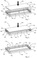
- the Fig. 1 to 3 show the assembly process of a shelf 100. During the assembly process, a wooden base plate 102 is inserted from above into a support frame 10 of the shelf 100.
- the base plate 102 is a rectangular decorative plate which has a circumferential side edge 104.
- the flat base plate 102 is designed without grooves and has a top side 106 and a bottom side 108.
- the support frame 10 comprises a profile strip 12 which runs completely around an inner frame area 14.
- the base plate 102 is to be inserted into the inner frame area 14 from above during the insertion process.
- the profile strip 12 is a one-piece body made of metal, so that the profile strip 12 forms a metal border for the base plate 102 after the base plate 102 has been inserted.
- the profile strip 12 also has four longitudinal sections 16a-16d which are connected to one another in the corner regions 18a-18d.
- the profile strip 12 forms a closed frame in which the profile strip 12 is bent or kinked in the corner regions 18a-18d.
- the profile strip 12 On the inside of the frame 24, the profile strip 12 has interrupted edges in the corner regions 18a-18d so that no edge collisions occur in the corner regions 18a-18d when the profile strip 12 is kinked or bent during the manufacture of the support frame 10.
- the profile strip 12 of the support frame 10 allows the base plate 102 to be inserted from above, so that the base plate can be moved downwards along the insertion direction 20a during the insertion process.
- the base plate 102 is fixed in a form-fitting and force-fitting manner to the inner frame side 24 of the profile strip 12.
- a railing 22 is placed on the surrounding profile strip 12, which serves to further stabilize the objects inserted into the tray 100.
- the profile strip 12 of the support frame 10 also allows a non-destructive removal of the base plate 102 after completion of the insertion process. This allows the user to combine different support frames 10 and base plates 102 with one another.
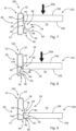
- the Fig. 4 to 6 show the open cross-sectional profile of the profile strip 12 during the insertion process of the base plate 102.
- the profile strip 12 has an inner leg 26 on the frame inner side 24.
- An outer leg 30 of the profile strip 12 is arranged on the frame outer side 28.
- the inner leg 26 and the outer leg 30 run parallel to one another in sections and are connected to one another via a curved strip section 32.
- the strip section 32 has a U-shaped connecting arch which extends over an angular range of 180°.
- the profile strip 12 comprises two free profile end sections 34, 36.
- the end section 34 runs parallel to the base plate 102.
- the profile strip 12 has a spring region 38 on the frame inner side 24 facing the frame inner region 14.
- the spring region 38 comprises a profile projection 40 extending in the form of a nose in the direction of the frame inner region 14.
- the profile projection 40 carries a contact section 42 which, before the base plate 102 is inserted (state as in Fig. 4 ) and after inserting the base plate 102 (cf. Fig. 6 ) extends obliquely towards the frame inner region 14.
- the contact section 42 When inserting the base plate 102 into the profile strip 12, the contact section 42 is pressed outwards from the base plate 102 (cf. Fig. 5 ). As a result, the spring area 38 is pressed into a space between the inner leg 26 and the outer leg 30, so that an insertion path for the base plate 102 is released in the direction of a receiving area 44 of the profile strip 12. As soon as the base plate 102 has reached the receiving area 44 of the profile strip 12, the spring area 38 carries out a return movement in the direction of the frame inner area 14. The return movement of the spring area 38 fixes the base plate 102 in a form-fitting and force-fitting manner to the frame inner side of the profile strip 12. The spring area 38 ensures that the base plate 12 is centered and fixed to the support frame 10.
- the profile end section 34 serves as a support for the base plate 102 located in the receiving area 44.
- the profile end section 36 serves as a lateral stop for the base plate 102 inserted into the receiving area 44.
- the suspension region 48 has a side edge contact surface 46, a top side contact surface 48 and a bottom side contact surface 50.
- the side edge contact surface 46 is in contact with the peripheral side edge 104 of the base plate 102.
- the top side contact surface 48 is also in contact with the top side 106 of the base plate 102 and the bottom side contact surface 50 is in contact with the bottom side 108 of the base plate 102.
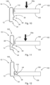
- the Fig. 7 to 9 show a support frame 10 in which the underside contact surface 50 is arranged on the inner leg 26.
- the profile end section 36 thus serves as a support for the inserted base plate 102.
- the Fig. 10 to 12 show the insertion process of a base plate 102, wherein the base plate 102 has a circumferential groove 110.
- the base plate 102 is again inserted in the insertion direction 20a from above into the circumferential profile strip 12.
- the profile end section 36 serves as an engagement element which engages in the circumferential groove 110 of the base plate 102 during the return movement of the spring region 38.
- the profile end section 36 thus functions again as a support for the base plate 102, wherein the supporting effect is not achieved by providing a support surface for the underside 108 of the base plate 102, but by the engagement of the profile end section 36 in the circumferential groove 110 of the base plate 102.
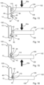
- the Fig. 13 to 16 show a support frame 10, wherein the profile strip 12 allows the insertion of the base plate 102 both from above (cf. Fig. 13, 14 and 16 ) as well as the insertion of the base plate 102 from below (cf. Fig. 15 and 16 ) allowed.
- the profile projection 40 when inserting the base plate 102 from above, i.e. from the insertion direction 20a, the profile projection 40 provides the contact section 42, which is pressed outwards by the base plate 102 during the insertion process.
- the underside of the profile end section 36 serves as a contact section 42 when the base plate 102 is inserted along the insertion direction 20b, i.e. from below, which is pressed outwards by the base plate 102 during the insertion process of the base plate 102.
- the respective contact section 42 of the suspension area 38 is pressed outwards in such a way that an insertion path for the base plate 102 is released in the direction of a receiving area 44.
- the suspension area 38 a return movement, whereby the base plate 102 is fixed and centered.
Landscapes
- Tables And Desks Characterized By Structural Shape (AREA)
- Connection Of Plates (AREA)
Description
- Die Erfindung betrifft einen Tragrahmen für ein Tablar mit einer teilweise oder vollständig um einen Rahmeninnenbereich umlaufenden Profilleiste, in welche eine Bodenplatte einsetzbar ist, wobei die Profilleiste auf der dem Rahmeninnenbereich zugewandten Rahmeninnenseite einen Federungsbereich aufweist, welcher einen Kontaktabschnitt umfasst, wobei der Kontaktabschnitt des Federungsbereichs dazu eingerichtet ist, beim Einsetzen der Bodenplatte in die Profilleiste von der Bodenplatte weggedrückt zu werden und dadurch einen Einsetzpfad für die Bodenplatte in Richtung eines Aufnahmebereichs freizugeben, wobei der Federungsbereich dazu eingerichtet ist, zum form- und/oder kraftschlüssigen Fixieren der Bodenplatte an der Rahmeninnenseite der Profilleiste eine Rückstellbewegung auszuführen, sobald die Bodenplatte den Aufnahmebereich erreicht hat, wobei sich der Kontaktabschnitt des Federungsbereichs in Einsetzrichtung der Bodenplatte vor und nach dem Einsetzen der Bodenplatte schräg in Richtung des Rahmeninnenbereichs erstreckt, sodass die Bodenplatte von oben oder von unten in die Profilleiste einsetzbar ist.
- Ferner betrifft die Erfindung ein Tablar, insbesondere ein Küchenschranktablar, mit einem Tragrahmen und einer Bodenplatte.
- Tablare werden insbesondere in Küchenschränken eingesetzt, um den vom Küchenschrank bereitgestellten Stauraum möglichst optimal nutzen zu können. Dabei sind die Tablare üblicherweise einzeln oder als Bestandteil einer übergeordneten Auszugseinheit aus dem Korpus des Küchenschranks herausziehbar, sodass ein hoher Verwendungskomfort gewährleistet wird.
- Ein derartiges Tablar ist beispielsweise aus der Druckschrift
DE 20 2019 106 557 U1 bekannt. Ein weiteres artverwandtes Möbel wird in der DruckschriftDE 20 2010 017 098 U1 vorgeschlagen. Ein in ein Schrankmöbel einsetzbarer Rahmen ist darüber hinaus in der DruckschriftDE 10 2011 009 566 A1 beschrieben. - Ferner ist aus der Druckschrift
WO 2020/053850 A1 ein verstärkter Regalboden bekannt. In der DruckschriftUS 2020/214446 A1 wird ein Gitterwandregal mit einer Baugruppe zur Festigkeitssteigerung offenbart. - Insbesondere im Küchenbau besteht der Bedarf an hochgradig individualisierbaren Küchenmöbeln, sodass Küchen auf den Bedarf und die Vorlieben der zukünftigen Verwender angepasst werden können. In diesem Zusammenhang besteht auch der Bedarf an modularen Tablaren, bei welchen unterschiedliche Kombinationen aus Tragrahmen und Bodenplatte realisierbar sind.
- Idealerweise soll eine Änderung der Tablarkonfiguration, beispielsweise durch Austauschen des Tragrahmens oder der Bodenplatte, durch den Verwender selbst ausgeführt werden, ohne dass hierfür Fachpersonal erforderlich ist. Insofern sollen entsprechende Tablare auch vergleichsweise einfach montierbar und demontierbar sein.
- Gleichzeitig darf mit der Modularität des Tablars jedoch keine Beeinträchtigung der Tragfähigkeit einhergehen. Aufgrund des Nachhaltigkeitsgedankens werden in vielen Küchen vergleichsweise leichte Kunststoffbehältnisse vermehrt durch Stein- und Glasgefäße ersetzt, sodass Tablare für moderne Küchen sogar über eine gesteigerte Tragfähigkeit verfügen sollten.
- Das modulare und eine hohe Tragfähigkeit aufweisende Tablar muss darüber hinaus mit einem akzeptablen Fertigungsaufwand herstellbar sein, sodass die Fertigungskosten eine vergleichsweise hohe Marktakzeptanz erlauben. Da in der Möbelfertigung die einzuhaltenden Fertigungstoleranzen einen erheblichen Einfluss auf die Herstellungskosten haben, besteht insofern der Bedarf an einer Tablarkonstruktion, welche geringe Anforderungen an die Fertigungstoleranz stellt.
- Die der Erfindung zugrundeliegende Aufgabe besteht also darin, die Bereitstellung eines modularen Tablars zu ermöglichen, welches eine hohe Tragfähigkeit aufweist und vergleichsweise kostengünstig herstellbar ist.
- Die Aufgabe wird gelöst durch einen Tragrahmen der eingangs genannten Art, wobei der Federungsbereich eine Oberseitenkontaktfläche aufweist, welche dazu eingerichtet ist, nach dem Einsetzen der Bodenplatte in den Aufnahmebereich mit der Oberseite der Bodenplatte in Kontakt zu stehen. Alternativ oder zusätzlich weist der Federungsbereich eine Unterseitenkontaktfläche auf, welche dazu eingerichtet ist, nach dem Einsetzen der Bodenplatte in den Aufnahmebereich mit der Unterseite der Bodenplatte in Kontakt zu stehen.
- Die Erfindung macht sich die Erkenntnis zunutze, dass das Einsetzen der Bodenplatte von oben oder von unten in die Profilleiste erforderlich ist, damit die Bodenplatte in eine teilweise oder vollständig um einen Rahmeninnenbereich umlaufende Profilleiste einsetzbar ist. In Kombination mit dem den Kontaktabschnitt tragenden Federungsbereich ist außerdem ein zerstörungsfreies Einsetzen und Entnehmen der Bodenplatte in den Tragrahmen möglich, sodass Verwender die Möglichkeit haben, unterschiedliche Tragrahmen und Bodenplatten miteinander zu kombinieren. Die zerstörungsfreie Entnehmbarkeit der Bodenplatte erlaubt außerdem einen aufwandsarmen Austausch der Bodenplatte, beispielsweise wenn diese beschädigt ist oder durch eine Bodenplatte eines anderen Typs ersetzt werden soll. Durch den sich schräg in Richtung des Rahmeninnenbereichs erstreckenden Kontaktabschnitt des Federungsbereichs werden außerdem vergleichsweise geringe Anforderungen an die einzuhaltenden Toleranzen bei der Fertigung des Tragrahmens und der Bodenplatte gestellt. Aufgrund der Nachgiebigkeit des Federungsbereichs können geringfügige Maßabweichungen ohne Beeinträchtigung der Tragfähigkeit oder des stabilen Sitzes der Bodenplatte in dem Tragrahmen ausgeglichen werden.
- Nach dem Einsetzen der Bodenplatte in den Tragrahmen weist die Bodenplatte vorzugsweise einen Festsitz innerhalb des Aufnahmebereichs der Profilleiste auf. Die Bodenplatte kann beispielsweise eine Dekorplatte sein. Ferner kann die Bodenplatte eine Holzplatte sein. Die Profilleiste des Tragrahmens ist vorzugsweise aus Metall ausgebildet und dient als Metallumrandung der Bodenplatte.
- In einer bevorzugten Ausführungsform des erfindungsgemäßen Tragrahmens ist der Kontaktabschnitt des Federungsbereichs dazu eingerichtet, beim Einsetzen der Bodenplatte in die Profilleiste von der Bodenplatte nach außen gedrückt zu werden. Beispielsweise kommt eine seitliche Kante der Bodenplatte beim Einsetzen der Bodenplatte in die Profilleiste mit dem Kontaktabschnitt des Federungsbereichs in Kontakt und übt eine Druckkraft auf den Kontaktabschnitt aus, sodass der Kontaktabschnitt des Federungsbereichs aufgrund der Druckkraft nach außen gedrückt wird. Alternativ oder zusätzlich kann der Federungsbereich des Tragrahmens dazu eingerichtet sein, die Rückstellbewegung zum form- und/oder kraftschlüssigen Fixieren der Bodenplatte an der Rahmeninnenseite der Profilleiste in Richtung des Rahmeninnenbereichs auszuführen. Nachdem der Kontaktabschnitt des Federungsbereichs beim Einsetzen der Bodenplatte nach außen gedrückt wurde, kommt es zu einer Rückstellbewegung der Profilleiste in die entgegengesetzte Richtung, also in Richtung des Rahmeninnenbereichs, sobald die Bodenplatte den Aufnahmebereich erreicht hat, sodass über die Rückstellbewegung des Federungsbereichs einerseits eine Zentrierung und andererseits eine Fixierung der Bodenplatte im Aufnahmebereich des Tragrahmens erfolgt.
- Der erfindungsgemäße Tragrahmen wird ferner dadurch vorteilhaft weitergebildet, dass die Profilleiste einen Innenschenkel und einen sich außen vom Innenschenkel befindenden Außenschenkel aufweist. Der Federungsbereich ist vorzugsweise Bestandteil des Innenschenkels, wobei sich zwischen dem Außenschenkel und dem Innenschenkel ein Freiraum befindet und der Federungsbereich dazu eingerichtet ist, sich beim Wegdrücken durch die Bodenplatte in den Freiraum hineinzubewegen. Zum Einsetzen der Bodenplatte in den Tragrahmen bzw. zum Entnehmen der Bodenplatte aus dem Tragrahmen ist also kein zusätzlicher Montage- bzw. Demontageraum erforderlich. Die Ausmaße des Tragrahmens verändern sich während des Montage- und Demontagevorgangs der Bodenplatte nicht. Der Innenschenkel und der Außenschenkel der Profilleiste verlaufen vorzugsweise zumindest entlang eines Abschnitts parallel zueinander. Der Innenschenkel und der Außenschenkel sind vorzugsweise über einen einen Verbindungsbogen aufweisenden Leistenabschnitt der Profilleiste miteinander verbunden.
- In einer anderen bevorzugten Ausführungsform des erfindungsgemäßen Tragrahmens weist die Profilleiste ein offenes Querschnittsprofil mit zwei freien Profilendabschnitten auf. Vorzugsweise ist ein Profilendabschnitt dazu eingerichtet, als Tragstütze für die eingesetzte Bodenplatte zu dienen. Der als Tragstütze dienende Profilendabschnitt kann beispielsweise Bestandteil des Federungsbereichs der Profilleiste sein. Ferner kann der als Tragstütze dienende Profilendabschnitt Bestandteil des Innenschenkels der Profilleiste sein. Alternativ oder zusätzlich ist ein Profilendabschnitt dazu eingerichtet, als seitlicher Anschlag für die eingesetzte Bodenplatte zu dienen. Der als seitliche Anschlag dienende Profilendabschnitt kann Bestandteil des Federungsbereichs sein. Ferner kann der als seitliche Anschlag dienende Profilendabschnitt Bestandteil des Innenschenkels der Profilleiste sein. Zwischen den Profilendabschnitten befindet sich vorzugsweise der einen Verbindungsbogen aufweisende Leistenabschnitt. Der Verbindungsbogen des Leistenabschnitts erstreckt sich vorzugsweise über einen Winkelbereich von etwa 180°. Vorzugsweise weist der Verbindungsbogen des Leistenabschnitts eine U-Form auf.
- Der erfindungsgemäße Tragrahmen wird ferner dadurch vorteilhaft weitergebildet, dass der Kontaktabschnitt des Federungsbereichs Bestandteil eines sich nasenförmig in Richtung des Rahmeninnenbereichs erstreckenden Profilvorsprungs der Profilleiste ist. Durch die Nasenform des sich in Richtung des Rahmeninnenbereichs erstreckenden Profilvorsprungs wird ein sich schräg in Richtung des Rahmeninnenbereichs erstreckender Kontaktabschnitt bereitgestellt, welcher beim Einsetzen der Bodenplatte in die Profilleiste von der Bodenplatte nach außen zur Freigabe eines Einsetzpfads für die Bodenplatte wegdrückbar ist. Vorzugsweise deckt der nasenförmige Profilvorsprung einen umlaufenden Kantenbereich der Bodenplatte ab, wenn sich die Bodenplatte in dem Aufnahmebereich der umlaufenden Profilleiste befindet. Etwaige Kantenbeschädigungen an der Bodenplatte werden somit durch den nasenförmigen Profilvorsprung abgedeckt und sind für den Verwender des Tablars nicht sichtbar.
- In einer anderen bevorzugten Ausführungsform des erfindungsgemäßen Tragrahmens weist der Federungsbereich eine Seitenkantenkontaktfläche auf, welche dazu eingerichtet ist, nach dem Einsetzen der Bodenplatte in den Aufnahmebereich mit der umlaufenden Seitenkante der Bodenplatte in Kontakt zu stehen. Dadurch, dass die Seitenkantenkontaktfläche nach dem Einsetzen der Bodenplatte in den Aufnahmebereich mit der umlaufenden Seitenkante der Bodenplatte in Kontakt steht, wird ein klapper- und spielfreier Sitz der Bodenplatte in dem Tragrahmen gewährleistet. Die Seitenkantenkontaktfläche wird vorzugsweise von dem Innenschenkel der Profilleiste getragen.
- Erfindungsgemäß weist der Federungsbereich eine Oberseitenkontaktfläche auf, welche dazu eingerichtet ist, nach dem Einsetzen der Bodenplatte in den Aufnahmebereich mit der Oberseite der Bodenplatte in Kontakt zu stehen. Alternativ oder zusätzlich weist der Federungsbereich eine Unterseitenkontaktfläche auf, welche dazu eingerichtet ist, nach dem Einsetzen der Bodenplatte in den Aufnahmebereich mit der Unterseite der Bodenplatte in Kontakt zu stehen. Die in dem Aufnahmebereich positionierte Bodenplatte wird also nach dem Einsetzen auch nach oben und unten gesichert, sodass ein unbeabsichtigtes Abheben der Bodenplatte von seiner Aufstandsfläche vermieden wird. Da ein unbeabsichtigtes Abheben der Bodenplatte von der Aufstandsfläche nicht möglich ist, besteht auch kein Verletzungsrisiko durch Einklemmen eines Fingers zwischen der Bodenplatte und der Profilleiste. Ein Tablar mit einem entsprechenden Tragrahmen kann also gefahrlos gereinigt und auch in Haushalten mit Kleinkindern verwendet werden.
- Es ist ferner ein erfindungsgemäßer Tragrahmen bevorzugt, bei welchem die Profilleiste in den Eckbereichen gebogen oder geknickt ausgebildet ist. Die teilweise oder vollständig umlaufende Profilleiste ist also vorzugsweise ein einstückiger Körper und nicht aus mehreren Leistenteilen zusammengesetzt. Vorzugsweise umfasst die Profilleiste vier Längsabschnitte, wobei aneinander angrenzende Längsabschnitte in den Eckbereichen miteinander verbunden sind.
- Der Tragrahmen kann ein geschlossener Rahmen sein, bei welchem die Profilleiste vollständig um den Rahmeninnenbereich umläuft. Ferner kann der Tragrahmen ein offener Rahmen sein, bei welchem die Profilleiste teilweise, insbesondere größtenteils, um den Rahmeninnenbereich umläuft. Wenn der Tragrahmen ein offener Rahmen ist, kann die Profilleiste beispielsweise geschlitzt sein. Vorzugsweise weist ein Längsabschnitt der Profilleiste zwei auf Stoß liegende und miteinander gefügte Längsteilabschnitte auf. Die auf Stoß liegenden und miteinander gefügten Längsteilabschnitte können laserverschweißt sein.
- In einer weiteren bevorzugten Ausführungsform des erfindungsgemäßen Tragrahmens weist die Profilleiste in den Eckbereichen auf der Rahmeninnenseite Unterbrechungskanten auf. Die innenliegenden Eckbereiche sind zum Umbiegen oder Umknicken der Profilleiste im Rahmen der Herstellung vorzugsweise freigelasert, sodass es beim Umbiegen bzw. Umknicken nicht zu einer Kantenkollision in den Eckbereichen auf der Rahmeninnenseite kommt.
- Es ist darüber hinaus ein erfindungsgemäßer Tragrahmen bevorzugt, bei welchem die Profilleiste als einstückiger Körper ausgebildet ist. Vorzugsweise ist die Profilleiste aus Metall ausgebildet bzw. eine Metallleiste. Die Profilleiste kann eine Beschichtung aufweisen. Die Profilleiste kann mit einem Pulverlack beschichtet sein. Ferner kann die Profilleiste eine galvanische Oberfläche aufweisen.
- Die der Erfindung zugrundeliegende Aufgabe wird ferner durch ein Tablar der eingangs genannten Art gelöst, wobei der Tragrahmen des erfindungsgemäßen Tablars nach einer der vorstehend beschriebenen Ausführungsformen ausgebildet ist und die Bodenplatte in den Rahmeninnenbereich des Tragrahmens einsetzbar oder eingesetzt ist. Hinsichtlich der Vorteile und Modifikationen des erfindungsgemäßen Tablars wird zunächst auf die Vorteile und Modifikationen des erfindungsgemäßen Tragrahmens verwiesen.
- Die Bodenplatte des Tablars ist vorzugsweise aus Holz ausgebildet. Die Bodenplatte kann nutenfrei ausgebildet sein, sodass eine aufwendige Bearbeitung der Bodenplatte, beispielsweise durch Fräsen, entfällt. In alternativen Ausführungsformen kann die Bodenplatte jedoch auch eine oder mehrere Nuten aufweisen.
- Nachfolgend werden bevorzugte Ausführungsformen der Erfindung unter Bezugnahme auf die beiliegenden Zeichnungen näher erläutert und beschrieben. Dabei zeigen:
- Fig. 1
- ein Ausführungsbeispiel des erfindungsgemäßen Tablars vor dem Einsetzen der Bodenplatte in einer perspektivischen Darstellung;
- Fig. 2
- das in der
Fig. 1 abgebildete Tablar während des Einsetzens der Bodenplatte in einer perspektivischen Darstellung; - Fig. 3
- das in der
Fig. 1 abgebildete Tablar nach Beendigung des Einsetzvorgangs der Bodenplatte in einer perspektivischen Darstellung; - Fig. 4
- das Querschnittsprofil der Profilleiste des Tragrahmens des in der
Fig. 1 abgebildeten Tablars während des Einsetzens der Bodenplatte in einem ersten Zustand; - Fig. 5
- das in der
Fig. 4 abgebildete Querschnittsprofil während des Einsetzens der Bodenplatte in einem zweiten Zustand; - Fig. 6
- das in der
Fig. 4 abgebildete Querschnittsprofil nach Beendigung des Einsetzvorgangs der Bodenplatte; - Fig. 7
- das Querschnittsprofil der Profilleiste eines erfindungsgemäßen Tragrahmens während des Einsetzens der Bodenplatte in einem ersten Zustand;
- Fig. 8
- das in der
Fig. 7 abgebildete Querschnittsprofil während des Einsetzens der Bodenplatte in einem zweiten Zustand; - Fig. 9
- das in der
Fig. 7 abgebildete Querschnittsprofil nach Beendigung des Einsetzvorgangs der Bodenplatte; - Fig. 10
- das Querschnittsprofil der Profilleiste eines erfindungsgemäßen Tragrahmens während des Einsetzens der Bodenplatte in einem ersten Zustand;
- Fig. 11
- das in der
Fig. 10 abgebildete Querschnittsprofil während des Einsetzens der Bodenplatte in einem zweiten Zustand; - Fig. 12
- das in der
Fig. 10 abgebildete Querschnittsprofil nach Beendigung des Einsetzvorgangs der Bodenplatte; - Fig. 13
- das Querschnittsprofil der Profilleiste eines erfindungsgemäßen Tragrahmens während des Einsetzens der Bodenplatte von oben in einem ersten Zustand;
- Fig. 14
- das in der
Fig. 13 abgebildete Querschnittsprofil während des Einsetzens der Bodenplatte von oben in einem zweiten Zustand; - Fig. 15
- das in der
Fig. 13 abgebildete Querschnittsprofil während des Einsetzens der Bodenplatte von unten; und - Fig. 16
- das in der
Fig. 13 abgebildete Querschnittsprofil nach Beendigung der Einsetzvorgänge der Bodenplatte von oben und von unten. - Die
Fig. 1 bis 3 zeigen den Montagevorgang eines Tablars 100. Im Rahmen des Montagevorgangs wird eine aus Holz ausgebildete Bodenplatte 102 von oben in einen Tragrahmen 10 des Tablars 100 eingesetzt. - Die Bodenplatte 102 ist eine rechteckige Dekorplatte, welche eine umlaufende Seitenkante 104 aufweist. Die flache Bodenplatte 102 ist nutenfrei ausgebildet und weist eine Oberseite 106 sowie eine Unterseite 108 auf.
- Der Tragrahmen 10 umfasst eine Profilleiste 12, welche vollständig um einen Rahmeninnenbereich 14 umläuft. Die Bodenplatte 102 ist im Rahmen des Einsetzvorgangs von oben in den Rahmeninnenbereich 14 einzusetzen. Die Profilleiste 12 ist ein einstückiger Körper aus Metall, sodass die Profilleiste 12 nach dem Einsetzen der Bodenplatte 102 eine Metallumrandung für die Bodenplatte 102 bildet. Die Profilleiste 12 weist ferner vier Längsabschnitte 16a-16d auf, welche in den Eckbereichen 18a-18d miteinander verbunden sind. Die Profilleiste 12 bildet einen geschlossenen Rahmen, bei welchem die Profilleiste 12 in den Eckbereichen 18a-18d gebogen oder geknickt ausgebildet ist. Auf der Rahmeninnenseite 24 weist die Profilleiste 12 in den Eckbereichen 18a-18d Unterbrechungskanten auf, sodass es in den Eckbereichen 18a-18d beim Knicken bzw. Umbiegen der Profilleiste 12 während der Herstellung des Tragrahmens 10 nicht zu Kantenkollisionen kommt.
- Die Profilleiste 12 des Tragrahmens 10 erlaubt ein Einsetzen der Bodenplatte 102 von oben, sodass die Bodenplatte im Rahmen des Einsetzvorgangs entlang der Einsetzrichtung 20a abwärtszubewegen ist. Bei Beendigung des Einsetzvorgangs (vgl.
Fig. 3 ) ist die Bodenplatte 102 form- und kraftschlüssig an der Rahmeninnenseite 24 der Profilleiste 12 fixiert. - Auf die umlaufende Profilleiste 12 ist ferner eine Reling 22 aufgesetzt, welche zur weiteren Stabilisierung der in das Tablar 100 eingesetzten Gegenstände dient.
- Die Profilleiste 12 des Tragrahmens 10 erlaubt auch eine zerstörungsfreie Entnahme der Bodenplatte 102 nach Beendigung des Einsetzvorgangs. Somit kann der Nutzer unterschiedliche Tragrahmen 10 und Bodenplatten 102 miteinander kombinieren.
- Die
Fig. 4 bis 6 zeigen das offene Querschnittsprofil der Profilleiste 12 während des Einsetzvorgangs der Bodenplatte 102. Die Profilleiste 12 weist auf der Rahmeninnenseite 24 einen Innenschenkel 26 auf. Auf der Rahmenaußenseite 28 ist ein Außenschenkel 30 der Profilleiste 12 angeordnet. Der Innenschenkel 26 und der Außenschenkel 30 verlaufen abschnittsweise parallel zueinander und sind über einen gebogenen Leistenabschnitt 32 miteinander verbunden. Der Leistenabschnitt 32 weist einen U-förmigen Verbindungsbogen auf, welcher sich über einen Winkelbereich von 180° erstreckt. - Die Profilleiste 12 umfasst aufgrund ihres offenen Querschnittsprofils zwei freie Profilendabschnitte 34, 36. Der Endabschnitt 34 verläuft parallel zu der Bodenplatte 102.
- Die Profilleiste 12 weist auf der dem Rahmeninnenbereich 14 zugewandten Rahmeninnenseite 24 einen Federungsbereich 38 auf. Der Federungsbereich 38 umfasst einen sich nasenförmig in Richtung des Rahmeninnenbereichs 14 erstreckenden Profilvorsprung 40. Der Profilvorsprung 40 trägt einen Kontaktabschnitt 42, welcher sich vor dem Einsetzen der Bodenplatte 102 (Zustand wie in
Fig. 4 ) und nach dem Einsetzen der Bodenplatte 102 (vgl.Fig. 6 ) schräg in Richtung des Rahmeninnenbereichs 14 erstreckt. - Beim Einsetzen der Bodenplatte 102 in die Profilleiste 12 wird der Kontaktabschnitt 42 von der Bodenplatte 102 nach außen gedrückt (vgl.
Fig. 5 ). Hierdurch wird der Federungsbereich 38 in einen Raum zwischen dem Innenschenkel 26 und dem Außenschenkel 30 gedrückt, sodass ein Einsetzpfad für die Bodenplatte 102 in Richtung eines Aufnahmebereichs 44 der Profilleiste 12 freigegeben wird. Sobald die Bodenplatte 102 den Aufnahmebereich 44 der Profilleiste 12 erreicht hat, führt der Federungsbereich 38 eine Rückstellbewegung in Richtung des Rahmeninnenbereichs 14 aus. Durch die Rückstellbewegung des Federungsbereichs 38 wird die Bodenplatte 102 form- und kraftschlüssig an der Rahmeninnenseite der Profilleiste 12 fixiert. Der Federungsbereich 38 sorgt für eine Zentrierung und Fixierung der Bodenplatte 12 am Tragrahmen 10. - Der Profilendabschnitt 34 dient als Tragstütze für die sich in dem Aufnahmebereich 44 befindende Bodenplatte 102. Der Profilendabschnitt 36 dient als seitlicher Anschlag für die in den Aufnahmebereich 44 eingesetzte Bodenplatte 102.
- Der Federungsbereich 48 weist eine Seitenkantenkontaktfläche 46, eine Oberseitenkontaktfläche 48 und eine Unterseitenkontaktfläche 50 auf. Nach dem Einsetzen der Bodenplatte 102 in den Aufnahmebereich 44 steht die Seitenkantenkontaktfläche 46 mit der umlaufenden Seitenkante 104 der Bodenplatte 102 in Kontakt. Nach Beendigung des Einsetzvorgangs steht ferner die Oberseitenkontaktfläche 48 in Kontakt mit der Oberseite 106 der Bodenplatte 102 und die Unterseitenkontaktfläche 50 steht in Kontakt mit der Unterseite 108 der Bodenplatte 102.
- Die
Fig. 7 bis 9 zeigen einen Tragrahmen 10, bei welchem die Unterseitenkontaktfläche 50 an dem Innenschenkel 26 angeordnet ist. Somit dient der Profilendabschnitt 36 als Tragstütze für die eingesetzte Bodenplatte 102. - Die
Fig. 10 bis 12 zeigen den Einsetzvorgang einer Bodenplatte 102, wobei die Bodenplatte 102 eine umlaufende Nut 110 aufweist. Die Bodenplatte 102 wird erneut in Einsetzrichtung 20a von oben in die umlaufende Profilleiste 12 eingesetzt. In diesem Fall dient jedoch der Profilendabschnitt 36 als Eingriffselement, welches bei der Rückstellbewegung des Federungsbereichs 38 in die umlaufende Nut 110 der Bodenplatte 102 eingreift. Der Profilendabschnitt 36 fungiert also erneut als Tragstütze für die Bodenplatte 102, wobei die Stützwirkung nicht durch die Bereitstellung einer Auflagefläche für die Unterseite 108 der Bodenplatte 102 erzielt wird, sondern durch den Eingriff des Profilendabschnitts 36 in die umlaufende Nut 110 der Bodenplatte 102. - Die
Fig. 13 bis 16 zeigen einen Tragrahmen 10, wobei die Profilleiste 12 das Einsetzen der Bodenplatte 102 sowohl von oben (vgl.Fig. 13, 14 und 16 ) als auch das Einsetzen der Bodenplatte 102 von unten (vgl.Fig. 15 und 16 ) erlaubt. - Wie die
Fig. 13 und 14 zeigen, stellt der Profilvorsprung 40 beim Einsetzen der Bodenplatte 102 von oben, also aus der Einsetzrichtung 20a, den Kontaktabschnitt 42 bereit, welcher während des Einsetzvorgangs von der Bodenplatte 102 nach außen gedrückt wird. - Wie die
Fig. 15 zeigt, dient die Unterseite des Profilendabschnitts 36 beim Einsetzen der Bodenplatte 102 entlang der Einsetzrichtung 20b, also von unten, als Kontaktabschnitt 42, welcher während des Einsetzvorgangs der Bodenplatte 102 von der Bodenplatte 102 nach außen gedrückt wird. In beiden Fällen, also beim Einsetzen der Bodenplatte 102 von oben als auch von unten, wird der jeweilige Kontaktabschnitt 42 des Federungsbereichs 38 so nach außen gedrückt, dass ein Einsetzpfad für die Bodenplatte 102 in Richtung eines Aufnahmebereichs 44 freigegeben wird. Sobald die Bodenplatte den Aufnahmebereich 44 erreicht hat (vgl.Fig. 16 ), führt der Federungsbereich 38 eine Rückstellbewegung aus, wodurch die Bodenplatte 102 fixiert und zentriert wird. -
- 10
- Tragrahmen
- 12
- Profilleiste
- 14
- Rahmeninnenbereich
- 16a-16d
- Längsabschnitte
- 18a-18d
- Eckbereiche
- 20a, 20b
- Einsetzrichtungen
- 22
- Reling
- 24
- Rahmeninnenseite
- 26
- Innenschenkel
- 28
- Rahmenaußenseite
- 30
- Außenschenkel
- 32
- Leistenabschnitt
- 34
- Profilendabschnitt
- 36
- Profilendabschnitt
- 38
- Federungsbereich
- 40
- Profilvorsprung
- 42
- Kontaktabschnitt
- 44
- Aufnahmebereich
- 46
- Seitenkantenkontaktfläche
- 48
- Oberseitenkontaktfläche
- 50
- Unterseitenkontaktfläche
- 100
- Tablar
- 102
- Bodenplatte
- 104
- Seitenkante
- 106
- Oberseite
- 108
- Unterseite
- 110
- Nut
Claims (10)
- Tragrahmen (10) für ein Tablar (100), mit- einer teilweise oder vollständig um einen Rahmeninnenbereich (14) umlaufenden Profilleiste (12), in welche eine Bodenplatte (102) einsetzbar ist,wobei die Profilleiste (12) auf der dem Rahmeninnenbereich (14) zugewandten Rahmeninnenseite (24) einen Federungsbereich (38) aufweist, welcher einen Kontaktabschnitt (42) umfasst, wobei der Kontaktabschnitt (42) des Federungsbereichs (38) dazu eingerichtet ist, beim Einsetzen der Bodenplatte (102) in die Profilleiste (12) von der Bodenplatte (102) weggedrückt zu werden und dadurch einen Einsetzpfad für die Bodenplatte (102) in Richtung eines Aufnahmebereichs (44) freizugeben, wobei der Federungsbereich (38) dazu eingerichtet ist, zum form- und/oder kraftschlüssigen Fixieren der Bodenplatte (102) an der Rahmeninnenseite (24) der Profilleiste (12) eine Rückstellbewegung auszuführen, sobald die Bodenplatte (102) den Aufnahmebereich (44) erreicht hat;wobei sich der Kontaktabschnitt (42) des Federungsbereichs (38) in Einsetzrichtung (20a, 20b) der Bodenplatte (102) vor und nach dem Einsetzen der Bodenplatte (102) schräg in Richtung des Rahmeninnenbereichs (14) erstreckt, sodass die Bodenplatte (102) von oben oder von unten in die Profilleiste (12) einsetzbar ist;dadurch gekennzeichnet, dass der Federungsbereich (38)- eine Oberseitenkontaktfläche (48) aufweist, welche dazu eingerichtet ist, nach dem Einsetzen der Bodenplatte (102) in den Aufnahmebereich (44) mit der Oberseite (106) der Bodenplatte (102) in Kontakt zu stehen; und/oder- eine Unterseitenkontaktfläche (50) aufweist, welche dazu eingerichtet ist, nach dem Einsetzen der Bodenplatte (102) in den Aufnahmebereich (44) mit der Unterseite (108) der Bodenplatte (102) in Kontakt zu stehen.
- Tragrahmen (10) nach Anspruch 1,
dadurch gekennzeichnet, dass- der Kontaktabschnitt (42) des Federungsbereichs (38) dazu eingerichtet ist, beim Einsetzen der Bodenplatte (102) in die Profilleiste (12) von der Bodenplatte (102) nach außen gedrückt zu werden; und/oder- der Federungsbereich (38) dazu eingerichtet ist, die Rückstellbewegung zum form- und/oder kraftschlüssigen Fixieren der Bodenplatte (102) an der Rahmeninnenseite (24) der Profilleiste (12) in Richtung des Rahmeninnenbereichs (14) auszuführen. - Tragrahmen (10) nach Anspruch 1 oder 2,
dadurch gekennzeichnet, dass die Profilleiste (12) einen Innenschenkel (26) und einen sich außen vom Innenschenkel (26) befindenden Außenschenkel (30) aufweist, wobei der Federungsbereich (38) Bestandteil des Innenschenkels (26) ist und wobei sich zwischen dem Außenschenkel (30) und dem Innenschenkel (26) ein Freiraum befindet und der Federungsbereich (38) dazu eingerichtet ist, sich beim Wegdrücken durch die Bodenplatte (102) in den Freiraum hineinzubewegen. - Tragrahmen (10) nach einem der vorstehenden Ansprüche,
dadurch gekennzeichnet, dass die Profilleiste (12) ein offenes Querschnittsprofil mit zwei freien Profilendabschnitten (34, 36) aufweist, wobei- ein Profilendabschnitt (34, 36) dazu eingerichtet ist, als Tragstütze für die eingesetzte Bodenplatte (102) zu dienen; und/oder- ein Profilendabschnitt (36) dazu eingerichtet ist, als seitlicher Anschlag für die eingesetzte Bodenplatte (102) zu dienen. - Tragrahmen (10) nach einem der vorstehenden Ansprüche,
dadurch gekennzeichnet, dass der Kontaktabschnitt (42) des Federungsbereichs (38) Bestandteil eines sich nasenförmig in Richtung des Rahmeninnenbereichs (14) erstreckenden Profilvorsprungs (40) der Profilleiste (12) ist. - Tragrahmen (10) nach einem der vorstehenden Ansprüche,
dadurch gekennzeichnet, dass der Federungsbereich (38) eine Seitenkantenkontaktfläche (46) aufweist, welche dazu eingerichtet ist, nach dem Einsetzen der Bodenplatte (102) in den Aufnahmebereich (44) mit der umlaufenden Seitenkante (104) der Bodenplatte (102) in Kontakt zu stehen. - Tragrahmen (10) nach einem der vorstehenden Ansprüche,
dadurch gekennzeichnet, dass die Profilleiste (12) in Eckbereichen (18a-18d) gebogen oder geknickt ausgebildet ist. - Tragrahmen (10) nach Anspruch 7,
dadurch gekennzeichnet, dass die Profilleiste (12) in den Eckbereichen (18a-18d) auf der Rahmeninnenseite (24) Unterbrechungskanten aufweist. - Tragrahmen (10) nach einem der vorstehenden Ansprüche,
dadurch gekennzeichnet, dass die Profilleiste (12) als einstückiger Körper ausgebildet ist. - Tablar (100), insbesondere Küchenschranktablar, mit- einem Tragrahmen (10); und- einer Bodenplatte (102)dadurch gekennzeichnet, dass der Tragrahmen (10) nach einem der vorstehenden Ansprüche ausgebildet ist und die Bodenplatte (102) in den Rahmeninnenbereich (14) des Tragrahmens (10) einsetzbar oder eingesetzt ist.
Applications Claiming Priority (1)
| Application Number | Priority Date | Filing Date | Title |
|---|---|---|---|
| DE102021112371.2A DE102021112371A1 (de) | 2021-05-12 | 2021-05-12 | Tragrahmen für ein Tablar |
Publications (2)
| Publication Number | Publication Date |
|---|---|
| EP4088619A1 EP4088619A1 (de) | 2022-11-16 |
| EP4088619B1 true EP4088619B1 (de) | 2025-01-29 |
Family
ID=81387033
Family Applications (1)
| Application Number | Title | Priority Date | Filing Date |
|---|---|---|---|
| EP22169930.9A Active EP4088619B1 (de) | 2021-05-12 | 2022-04-26 | Tragrahmen für ein tablar |
Country Status (4)
| Country | Link |
|---|---|
| EP (1) | EP4088619B1 (de) |
| CN (1) | CN115336870A (de) |
| DE (1) | DE102021112371A1 (de) |
| PL (1) | PL4088619T3 (de) |
Family Cites Families (16)
| Publication number | Priority date | Publication date | Assignee | Title |
|---|---|---|---|---|
| DE4437630C1 (de) * | 1994-10-21 | 1996-01-25 | Raymond A Gmbh & Co Kg | Haltevorrichtung zur Befestigung eines Geräteeinsatzes in einer Grundplatte |
| US6422673B1 (en) * | 2001-04-16 | 2002-07-23 | Gemtron Corporation | Refrigerator compartment housing vertically adjustable shelves, each formed from a piece of tempered glass snapped-fastened to an injection molded frame |
| DE10349534A1 (de) | 2003-10-22 | 2005-06-16 | Versatile Systems Gmbh | Verbindungselement für Möbelelemente, Möbelelement und Möbelsystem, insbesondere Regalsystem |
| DE202005008286U1 (de) * | 2005-05-27 | 2006-10-05 | Paul Hettich Gmbh & Co. Kg | Schubkasten |
| CN2919791Y (zh) * | 2006-03-09 | 2007-07-04 | 鸿富锦精密工业(深圳)有限公司 | 电子设备机壳 |
| DE202007001780U1 (de) * | 2006-09-08 | 2008-01-10 | Paul Hettich Gmbh & Co. Kg | Schubkasten |
| AT505177B1 (de) * | 2007-05-09 | 2012-01-15 | Blum Gmbh Julius | Schublade mit schubladenunterteilung |
| DE202010002133U1 (de) | 2010-02-09 | 2010-06-10 | Hettich-Heinze Gmbh & Co. Kg | Rahmen für Möbel |
| DE202010017098U1 (de) | 2010-12-30 | 2012-04-02 | moll Funktionsmöbel GmbH | Möbelplattenteil und damit ausgestattetes Möbel |
| DE102012104457A1 (de) * | 2012-05-23 | 2013-11-28 | Paul Hettich Gmbh & Co. Kg | Fixierungsanordnung und Schubkasten |
| CN106617810B (zh) * | 2017-01-23 | 2022-11-04 | 无锡海达尔精密滑轨股份有限公司 | 用于抽屉滑轨的外挂式自动回收装置 |
| CN207814180U (zh) * | 2018-01-30 | 2018-09-04 | 宁德时代新能源科技股份有限公司 | 螺母组件及高压盒 |
| CN208863846U (zh) * | 2018-06-15 | 2019-05-17 | 江西金都保险设备集团有限公司 | 一种新型铝合金密集架专用门条结构 |
| IL261817B (en) * | 2018-09-16 | 2022-02-01 | Keter Plastic Ltd | A reinforced shelf, a kit and a shelving system that includes a reinforced shelf |
| US20200214446A1 (en) * | 2019-01-08 | 2020-07-09 | Rodrigo Ceron | Decorative and strength enhancing assembly for wire shelving |
| DE202019106557U1 (de) | 2019-11-26 | 2020-01-07 | Anton Schneider Gmbh & Co Kg | Tablar mit steckbaren Aufbauten |
-
2021
- 2021-05-12 DE DE102021112371.2A patent/DE102021112371A1/de active Pending
-
2022
- 2022-04-26 PL PL22169930.9T patent/PL4088619T3/pl unknown
- 2022-04-26 EP EP22169930.9A patent/EP4088619B1/de active Active
- 2022-05-12 CN CN202210517519.1A patent/CN115336870A/zh active Pending
Also Published As
| Publication number | Publication date |
|---|---|
| PL4088619T3 (pl) | 2025-06-23 |
| CN115336870A (zh) | 2022-11-15 |
| EP4088619A1 (de) | 2022-11-16 |
| DE102021112371A1 (de) | 2022-11-17 |
Similar Documents
| Publication | Publication Date | Title |
|---|---|---|
| EP2916688B1 (de) | Schubladenausziehführung | |
| WO2009118316A1 (de) | Teleskopierbare auszugsführung | |
| EP1540253A1 (de) | Schienen- und teleskopauszug | |
| EP2085332B1 (de) | Fachbodenebene für ein Lagerregal | |
| EP2316317B1 (de) | Großküchengerät, insbesondere Tablett-Transportwagen | |
| EP2465404B1 (de) | Geschirrspülmaschine, insbesondere Haushalts-Geschirrspülmaschine | |
| AT520691B1 (de) | Führungssystem | |
| DE2707365A1 (de) | Moebel mit einer ueber fuehrungsschienen ausziehbaren schublade | |
| DE19755339A1 (de) | Korb für Geschirrspülmaschine und dessen Herstellungsverfahren | |
| EP4088619A1 (de) | Tragrahmen für ein tablar | |
| AT522530A2 (de) | Korpusschiene mit Versteifungselement | |
| EP0275425B1 (de) | Regalboden aus Schichtwerkstoff | |
| EP2500661B1 (de) | Vorrichtung mit einem Gargutträger, für ein Gargerät, Gargerät mit einem entsprechenden Vorrichtung sowie Verfahren zum Bewegen eines Gargutträgers in einer Aufnahme | |
| EP3029383B1 (de) | Dunstabzugshaube | |
| DE202014104926U1 (de) | Wandbauteil, Schublade mit einem solchen Wandbauteil und Möbel | |
| EP3685705B1 (de) | Betriebseinrichtung mit zwei profilen und einer wand | |
| EP0563933B1 (de) | Eckschrank | |
| WO2012113595A1 (de) | Bodenblech mit unterseitiger verstärkungsstrebe | |
| DE102004025755A1 (de) | Schublade | |
| DE10057619B4 (de) | Auszugssystem | |
| DE10213640A1 (de) | Ausziehbares Gestell für Möbel, versehen mit einem Trägergehäuse zum Schutz der Gleitführungen | |
| EP1323371A2 (de) | Rollenführung für insbesondere schubladenartig herausziehbare Behältnisse von Haushaltsgeräten, insbesondere Geschirrspülmaschinen | |
| EP1827171B1 (de) | Ablagekorb | |
| WO2024213348A1 (de) | Tablar für einen schrankauszug | |
| EP2730197A1 (de) | Möbel und Möbelausschub für eine verschiebbare Anordnung über Führungsmittel |
Legal Events
| Date | Code | Title | Description |
|---|---|---|---|
| PUAI | Public reference made under article 153(3) epc to a published international application that has entered the european phase |
Free format text: ORIGINAL CODE: 0009012 |
|
| STAA | Information on the status of an ep patent application or granted ep patent |
Free format text: STATUS: THE APPLICATION HAS BEEN PUBLISHED |
|
| AK | Designated contracting states |
Kind code of ref document: A1 Designated state(s): AL AT BE BG CH CY CZ DE DK EE ES FI FR GB GR HR HU IE IS IT LI LT LU LV MC MK MT NL NO PL PT RO RS SE SI SK SM TR |
|
| STAA | Information on the status of an ep patent application or granted ep patent |
Free format text: STATUS: REQUEST FOR EXAMINATION WAS MADE |
|
| 17P | Request for examination filed |
Effective date: 20230406 |
|
| RBV | Designated contracting states (corrected) |
Designated state(s): AL AT BE BG CH CY CZ DE DK EE ES FI FR GB GR HR HU IE IS IT LI LT LU LV MC MK MT NL NO PL PT RO RS SE SI SK SM TR |
|
| P01 | Opt-out of the competence of the unified patent court (upc) registered |
Effective date: 20230515 |
|
| P02 | Opt-out of the competence of the unified patent court (upc) changed |
Effective date: 20230606 |
|
| STAA | Information on the status of an ep patent application or granted ep patent |
Free format text: STATUS: EXAMINATION IS IN PROGRESS |
|
| 17Q | First examination report despatched |
Effective date: 20240304 |
|
| GRAP | Despatch of communication of intention to grant a patent |
Free format text: ORIGINAL CODE: EPIDOSNIGR1 |
|
| STAA | Information on the status of an ep patent application or granted ep patent |
Free format text: STATUS: GRANT OF PATENT IS INTENDED |
|
| INTG | Intention to grant announced |
Effective date: 20241029 |
|
| GRAS | Grant fee paid |
Free format text: ORIGINAL CODE: EPIDOSNIGR3 |
|
| GRAA | (expected) grant |
Free format text: ORIGINAL CODE: 0009210 |
|
| STAA | Information on the status of an ep patent application or granted ep patent |
Free format text: STATUS: THE PATENT HAS BEEN GRANTED |
|
| AK | Designated contracting states |
Kind code of ref document: B1 Designated state(s): AL AT BE BG CH CY CZ DE DK EE ES FI FR GB GR HR HU IE IS IT LI LT LU LV MC MK MT NL NO PL PT RO RS SE SI SK SM TR |
|
| REG | Reference to a national code |
Ref country code: GB Ref legal event code: FG4D Free format text: NOT ENGLISH |
|
| REG | Reference to a national code |
Ref country code: CH Ref legal event code: EP |
|
| REG | Reference to a national code |
Ref country code: DE Ref legal event code: R096 Ref document number: 502022002746 Country of ref document: DE |
|
| REG | Reference to a national code |
Ref country code: IE Ref legal event code: FG4D Free format text: LANGUAGE OF EP DOCUMENT: GERMAN |
|
| REG | Reference to a national code |
Ref country code: NL Ref legal event code: MP Effective date: 20250129 |
|
| PG25 | Lapsed in a contracting state [announced via postgrant information from national office to epo] |
Ref country code: NL Free format text: LAPSE BECAUSE OF FAILURE TO SUBMIT A TRANSLATION OF THE DESCRIPTION OR TO PAY THE FEE WITHIN THE PRESCRIBED TIME-LIMIT Effective date: 20250129 |
|
| PG25 | Lapsed in a contracting state [announced via postgrant information from national office to epo] |
Ref country code: RS Free format text: LAPSE BECAUSE OF FAILURE TO SUBMIT A TRANSLATION OF THE DESCRIPTION OR TO PAY THE FEE WITHIN THE PRESCRIBED TIME-LIMIT Effective date: 20250429 |
|
| PG25 | Lapsed in a contracting state [announced via postgrant information from national office to epo] |
Ref country code: FI Free format text: LAPSE BECAUSE OF FAILURE TO SUBMIT A TRANSLATION OF THE DESCRIPTION OR TO PAY THE FEE WITHIN THE PRESCRIBED TIME-LIMIT Effective date: 20250129 |
|
| PGFP | Annual fee paid to national office [announced via postgrant information from national office to epo] |
Ref country code: PL Payment date: 20250416 Year of fee payment: 4 Ref country code: DE Payment date: 20250417 Year of fee payment: 4 |
|
| PG25 | Lapsed in a contracting state [announced via postgrant information from national office to epo] |
Ref country code: ES Free format text: LAPSE BECAUSE OF FAILURE TO SUBMIT A TRANSLATION OF THE DESCRIPTION OR TO PAY THE FEE WITHIN THE PRESCRIBED TIME-LIMIT Effective date: 20250129 |
|
| REG | Reference to a national code |
Ref country code: LT Ref legal event code: MG9D |
|
| PG25 | Lapsed in a contracting state [announced via postgrant information from national office to epo] |
Ref country code: NO Free format text: LAPSE BECAUSE OF FAILURE TO SUBMIT A TRANSLATION OF THE DESCRIPTION OR TO PAY THE FEE WITHIN THE PRESCRIBED TIME-LIMIT Effective date: 20250429 Ref country code: IS Free format text: LAPSE BECAUSE OF FAILURE TO SUBMIT A TRANSLATION OF THE DESCRIPTION OR TO PAY THE FEE WITHIN THE PRESCRIBED TIME-LIMIT Effective date: 20250529 |
|
| PGFP | Annual fee paid to national office [announced via postgrant information from national office to epo] |
Ref country code: IT Payment date: 20250430 Year of fee payment: 4 |
|
| PG25 | Lapsed in a contracting state [announced via postgrant information from national office to epo] |
Ref country code: HR Free format text: LAPSE BECAUSE OF FAILURE TO SUBMIT A TRANSLATION OF THE DESCRIPTION OR TO PAY THE FEE WITHIN THE PRESCRIBED TIME-LIMIT Effective date: 20250129 |
|
| PG25 | Lapsed in a contracting state [announced via postgrant information from national office to epo] |
Ref country code: LV Free format text: LAPSE BECAUSE OF FAILURE TO SUBMIT A TRANSLATION OF THE DESCRIPTION OR TO PAY THE FEE WITHIN THE PRESCRIBED TIME-LIMIT Effective date: 20250129 Ref country code: PT Free format text: LAPSE BECAUSE OF FAILURE TO SUBMIT A TRANSLATION OF THE DESCRIPTION OR TO PAY THE FEE WITHIN THE PRESCRIBED TIME-LIMIT Effective date: 20250529 |
|
| PG25 | Lapsed in a contracting state [announced via postgrant information from national office to epo] |
Ref country code: GR Free format text: LAPSE BECAUSE OF FAILURE TO SUBMIT A TRANSLATION OF THE DESCRIPTION OR TO PAY THE FEE WITHIN THE PRESCRIBED TIME-LIMIT Effective date: 20250430 Ref country code: BG Free format text: LAPSE BECAUSE OF FAILURE TO SUBMIT A TRANSLATION OF THE DESCRIPTION OR TO PAY THE FEE WITHIN THE PRESCRIBED TIME-LIMIT Effective date: 20250129 |
|
| PGFP | Annual fee paid to national office [announced via postgrant information from national office to epo] |
Ref country code: AT Payment date: 20250721 Year of fee payment: 4 |
|
| PGFP | Annual fee paid to national office [announced via postgrant information from national office to epo] |
Ref country code: TR Payment date: 20250421 Year of fee payment: 4 |
|
| PG25 | Lapsed in a contracting state [announced via postgrant information from national office to epo] |
Ref country code: SE Free format text: LAPSE BECAUSE OF FAILURE TO SUBMIT A TRANSLATION OF THE DESCRIPTION OR TO PAY THE FEE WITHIN THE PRESCRIBED TIME-LIMIT Effective date: 20250129 |
|
| PG25 | Lapsed in a contracting state [announced via postgrant information from national office to epo] |
Ref country code: SM Free format text: LAPSE BECAUSE OF FAILURE TO SUBMIT A TRANSLATION OF THE DESCRIPTION OR TO PAY THE FEE WITHIN THE PRESCRIBED TIME-LIMIT Effective date: 20250129 |
|
| PG25 | Lapsed in a contracting state [announced via postgrant information from national office to epo] |
Ref country code: DK Free format text: LAPSE BECAUSE OF FAILURE TO SUBMIT A TRANSLATION OF THE DESCRIPTION OR TO PAY THE FEE WITHIN THE PRESCRIBED TIME-LIMIT Effective date: 20250129 |
|
| PG25 | Lapsed in a contracting state [announced via postgrant information from national office to epo] |
Ref country code: CZ Free format text: LAPSE BECAUSE OF FAILURE TO SUBMIT A TRANSLATION OF THE DESCRIPTION OR TO PAY THE FEE WITHIN THE PRESCRIBED TIME-LIMIT Effective date: 20250129 Ref country code: EE Free format text: LAPSE BECAUSE OF FAILURE TO SUBMIT A TRANSLATION OF THE DESCRIPTION OR TO PAY THE FEE WITHIN THE PRESCRIBED TIME-LIMIT Effective date: 20250129 |
|
| PG25 | Lapsed in a contracting state [announced via postgrant information from national office to epo] |
Ref country code: RO Free format text: LAPSE BECAUSE OF FAILURE TO SUBMIT A TRANSLATION OF THE DESCRIPTION OR TO PAY THE FEE WITHIN THE PRESCRIBED TIME-LIMIT Effective date: 20250129 |
|
| PG25 | Lapsed in a contracting state [announced via postgrant information from national office to epo] |
Ref country code: SK Free format text: LAPSE BECAUSE OF FAILURE TO SUBMIT A TRANSLATION OF THE DESCRIPTION OR TO PAY THE FEE WITHIN THE PRESCRIBED TIME-LIMIT Effective date: 20250129 |
|
| REG | Reference to a national code |
Ref country code: DE Ref legal event code: R097 Ref document number: 502022002746 Country of ref document: DE |
|
| REG | Reference to a national code |
Ref country code: CH Ref legal event code: H13 Free format text: ST27 STATUS EVENT CODE: U-0-0-H10-H13 (AS PROVIDED BY THE NATIONAL OFFICE) Effective date: 20251125 |
|
| PLBE | No opposition filed within time limit |
Free format text: ORIGINAL CODE: 0009261 |
|
| STAA | Information on the status of an ep patent application or granted ep patent |
Free format text: STATUS: NO OPPOSITION FILED WITHIN TIME LIMIT |
|
| PG25 | Lapsed in a contracting state [announced via postgrant information from national office to epo] |
Ref country code: LU Free format text: LAPSE BECAUSE OF NON-PAYMENT OF DUE FEES Effective date: 20250426 |
|
| PG25 | Lapsed in a contracting state [announced via postgrant information from national office to epo] |
Ref country code: MC Free format text: LAPSE BECAUSE OF FAILURE TO SUBMIT A TRANSLATION OF THE DESCRIPTION OR TO PAY THE FEE WITHIN THE PRESCRIBED TIME-LIMIT Effective date: 20250129 |
|
| REG | Reference to a national code |
Ref country code: BE Ref legal event code: MM Effective date: 20250430 |
|
| 26N | No opposition filed |
Effective date: 20251030 |
|
| PG25 | Lapsed in a contracting state [announced via postgrant information from national office to epo] |
Ref country code: FR Free format text: LAPSE BECAUSE OF NON-PAYMENT OF DUE FEES Effective date: 20250430 |
|
| PG25 | Lapsed in a contracting state [announced via postgrant information from national office to epo] |
Ref country code: BE Free format text: LAPSE BECAUSE OF NON-PAYMENT OF DUE FEES Effective date: 20250430 |
|
| PG25 | Lapsed in a contracting state [announced via postgrant information from national office to epo] |
Ref country code: CH Free format text: LAPSE BECAUSE OF NON-PAYMENT OF DUE FEES Effective date: 20250430 |
|
| PG25 | Lapsed in a contracting state [announced via postgrant information from national office to epo] |
Ref country code: IE Free format text: LAPSE BECAUSE OF NON-PAYMENT OF DUE FEES Effective date: 20250426 |