EP4087376B1 - Lenkvorrichtung - Google Patents
Lenkvorrichtung Download PDFInfo
- Publication number
- EP4087376B1 EP4087376B1 EP22169018.3A EP22169018A EP4087376B1 EP 4087376 B1 EP4087376 B1 EP 4087376B1 EP 22169018 A EP22169018 A EP 22169018A EP 4087376 B1 EP4087376 B1 EP 4087376B1
- Authority
- EP
- European Patent Office
- Prior art keywords
- control device
- motor
- steering
- unit
- speed reducer
- Prior art date
- Legal status (The legal status is an assumption and is not a legal conclusion. Google has not performed a legal analysis and makes no representation as to the accuracy of the status listed.)
- Active
Links
Images


Classifications
-
- B—PERFORMING OPERATIONS; TRANSPORTING
- B62—LAND VEHICLES FOR TRAVELLING OTHERWISE THAN ON RAILS
- B62D—MOTOR VEHICLES; TRAILERS
- B62D5/00—Power-assisted or power-driven steering
- B62D5/04—Power-assisted or power-driven steering electrical, e.g. using an electric servo-motor connected to, or forming part of, the steering gear
- B62D5/0403—Power-assisted or power-driven steering electrical, e.g. using an electric servo-motor connected to, or forming part of, the steering gear characterised by constructional features, e.g. common housing for motor and gear box
- B62D5/0406—Power-assisted or power-driven steering electrical, e.g. using an electric servo-motor connected to, or forming part of, the steering gear characterised by constructional features, e.g. common housing for motor and gear box including housing for electronic control unit
-
- B—PERFORMING OPERATIONS; TRANSPORTING
- B62—LAND VEHICLES FOR TRAVELLING OTHERWISE THAN ON RAILS
- B62D—MOTOR VEHICLES; TRAILERS
- B62D5/00—Power-assisted or power-driven steering
- B62D5/04—Power-assisted or power-driven steering electrical, e.g. using an electric servo-motor connected to, or forming part of, the steering gear
- B62D5/0457—Power-assisted or power-driven steering electrical, e.g. using an electric servo-motor connected to, or forming part of, the steering gear characterised by control features of the drive means as such
- B62D5/046—Controlling the motor
- B62D5/0463—Controlling the motor calculating assisting torque from the motor based on driver input
-
- B—PERFORMING OPERATIONS; TRANSPORTING
- B62—LAND VEHICLES FOR TRAVELLING OTHERWISE THAN ON RAILS
- B62D—MOTOR VEHICLES; TRAILERS
- B62D5/00—Power-assisted or power-driven steering
- B62D5/04—Power-assisted or power-driven steering electrical, e.g. using an electric servo-motor connected to, or forming part of, the steering gear
- B62D5/0421—Electric motor acting on or near steering gear
- B62D5/0424—Electric motor acting on or near steering gear the axes of motor and final driven element of steering gear, e.g. rack, being parallel
- B62D5/0427—Electric motor acting on or near steering gear the axes of motor and final driven element of steering gear, e.g. rack, being parallel the axes being coaxial
-
- B—PERFORMING OPERATIONS; TRANSPORTING
- B62—LAND VEHICLES FOR TRAVELLING OTHERWISE THAN ON RAILS
- B62D—MOTOR VEHICLES; TRAILERS
- B62D5/00—Power-assisted or power-driven steering
- B62D5/04—Power-assisted or power-driven steering electrical, e.g. using an electric servo-motor connected to, or forming part of, the steering gear
- B62D5/0457—Power-assisted or power-driven steering electrical, e.g. using an electric servo-motor connected to, or forming part of, the steering gear characterised by control features of the drive means as such
- B62D5/046—Controlling the motor
-
- B—PERFORMING OPERATIONS; TRANSPORTING
- B62—LAND VEHICLES FOR TRAVELLING OTHERWISE THAN ON RAILS
- B62D—MOTOR VEHICLES; TRAILERS
- B62D6/00—Arrangements for automatically controlling steering depending on driving conditions sensed and responded to, e.g. control circuits
-
- F—MECHANICAL ENGINEERING; LIGHTING; HEATING; WEAPONS; BLASTING
- F16—ENGINEERING ELEMENTS AND UNITS; GENERAL MEASURES FOR PRODUCING AND MAINTAINING EFFECTIVE FUNCTIONING OF MACHINES OR INSTALLATIONS; THERMAL INSULATION IN GENERAL
- F16H—GEARING
- F16H1/00—Toothed gearings for conveying rotary motion
- F16H1/02—Toothed gearings for conveying rotary motion without gears having orbital motion
- F16H1/20—Toothed gearings for conveying rotary motion without gears having orbital motion involving more than two intermeshing members
- F16H1/206—Toothed gearings for conveying rotary motion without gears having orbital motion involving more than two intermeshing members characterised by the driving or driven member being composed of two or more gear wheels
-
- H—ELECTRICITY
- H02—GENERATION; CONVERSION OR DISTRIBUTION OF ELECTRIC POWER
- H02K—DYNAMO-ELECTRIC MACHINES
- H02K11/00—Structural association of dynamo-electric machines with electric components or with devices for shielding, monitoring or protection
- H02K11/20—Structural association of dynamo-electric machines with electric components or with devices for shielding, monitoring or protection for measuring, monitoring, testing, protecting or switching
-
- H—ELECTRICITY
- H02—GENERATION; CONVERSION OR DISTRIBUTION OF ELECTRIC POWER
- H02K—DYNAMO-ELECTRIC MACHINES
- H02K7/00—Arrangements for handling mechanical energy structurally associated with dynamo-electric machines, e.g. structural association with mechanical driving motors or auxiliary dynamo-electric machines
- H02K7/003—Couplings; Details of shafts
-
- B—PERFORMING OPERATIONS; TRANSPORTING
- B62—LAND VEHICLES FOR TRAVELLING OTHERWISE THAN ON RAILS
- B62D—MOTOR VEHICLES; TRAILERS
- B62D3/00—Steering gears
- B62D3/02—Steering gears mechanical
Definitions
- the present disclosure relates to a steering device.
- a steering device installed in a vehicle or the like receives rotation input in accordance with operation of a steering wheel or the like and outputs rotation via a speed reducer.
- studies are conducted on steering devices having steer-by-wire configuration instead of being connected to a steering shaft coupled to a steering wheel.
- a motor controls steering in accordance with the operation angle of the steering wheel.
- Patent Literature 1 discloses a steering device in which an assisting force is provided in steering directions to reduce the load of operation.
- the steering device disclosed in Patent Literature 1 includes: an input shaft having a worm wheel and configured to receive rotation based on operation; and an assistance power unit having a worm shaft meshing with the worm wheel and configured to provide an assisting force in the rotational direction of the input shaft.
- Patent Literature 1 U.S. Patent Application Publication No. 2020/0156697
- the worm shaft and the worm wheel have rotational axes orthogonal to each other. This may result in large-sized device configuration of the object to which the steering device is mounted.
- Document US 9 685 837 B2 relates to a driving device for steering a vehicle including a housing cover formed with a power supply connector; an insert mold installed in the housing cover and formed with a connecting connector; a printed circuit board disposed on one side of the insert mold; a motor driving module disposed on one side of the printed circuit board, formed with a first power connecting portion which is connected to the connecting connector by being installed in the housing cover, having a relay circuit portion which is connected to the first power connecting portion to switch power and three inverter circuit portions which are connected to the relay circuit portion, and formed with a second power connecting portion which is connected to the respective inverter circuit portions; and a motor portion disposed on one side of the motor driving module, and having a motor connector connected to the second power connecting portion.
- Document US 2018 / 219 450 A1 relates to a drive apparatus, which includes a motor and a control unit.
- the control unit has a heat sink secured to a cover.
- the motor is equipped with leads extending toward the control unit through a housing.
- the control unit has a substrate, which is equipped with connectors detachably joined to the leads, thereby eliminating soldering or welding to achieve an electrical connection of the motor and the control unit.
- Such a connection is accomplished by inserting the leads into the connectors, thus eliminating the need for a special and large-sized equipment and resulting in a decrease in production cost of the drive apparatus.
- the non-destructive disassembling of the motor and the control unit is achieved by disengaging them from each other to remove the second terminal from the first terminal.
- An angle sensing unit for sensing a rotational angle of the arm may be provided between the arm and the motor.
- the control device may include a first control device and a second control device for controlling the motor.
- the motor may include a first three-phase coil unit controlled by the first control device and a second three-phase coil unit controlled by the second control device.
- the first control device may include a first switching unit for controlling connection at a first connection unit at which terminals of the first three-phase coil unit are connected.
- the second control device may include a second switching unit for controlling connection at a second connection unit at which terminals of the second three-phase coil unit are connected.
- the configuration of the steering device can be downsized.
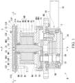
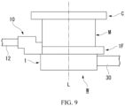
- a steering device W includes: a speed reducer 1; a motor M disposed on the first surface 1A side of the speed reducer 1; and a control device C provided on the motor M.
- the steering device W is a steer-by-wire device, in which a sensor senses operation information and instruction information of a vehicle body, and based on the sensing values of the sensor, the control device C causes the motor M to input to the speed reducer 1 a rotational power for producing a steering angle in accordance with the amount of operation.
- the operation information is output in accordance with the amount of operation of devices for inputting operation such as a steering wheel or a lever.
- the instruction information of the vehicle body is output from a vehicle stability control device, automated driving device or the like.
- the steering device W is applicable to steering of a front wheel of a vehicle, and it is also applicable to steering of a rear wheel.
- the steering device W is applicable to a commercial truck or a combination vehicle having three or more axles.
- the steering device W is applicable to a passenger car.
- the steering device W for example, the speed reducer 1, the motor M, and the control device C are centered at the central axis L that is aligned with the output axis of the speed reducer 1. Therefore, the steering device W can have a smaller width along the central axis L direction than in conventional arts, such that its size can be small.
- the control device C controls the motor M based on the rotational angle of the rotational driving force applied in the operation.
- the speed reducer 1 decelerates the rotational power input from the motor M to increase the torque and outputs the rotational output.
- the speed reducer 1 includes an output section 2 having a cylindrical shape, for example.
- the output section 2 is configured to output the rotational output.
- the speed reducer 1 will be described in detail later.
- the rotational power of the motor M is input to the first surface (one surface) 1A side of the speed reducer 1 in the central axis L direction.
- the rotational output is output to the second surface (the other surface) 1B side of the speed reducer 1 in the central axis L direction.
- the central axis L is aligned with the output axis of the speed reducer 1.
- the direction around the central axis L is referred to as the circumferential direction
- the direction orthogonal to the central axis L is referred to as the radial direction.
- the fixing member 1F has a first surface to which the speed reducer 1 is connected.
- the fixing member 1F has a second surface (the surface opposite to the first surface) to which a first end MA of the motor M is fixed.
- the control device C is connected to a second end MB of the motor M.
- the motor M is, for example, a brushless motor controlled by the control device C.
- the motor M may also be a brush motor.
- the motor M produces a rotational power in the rotational direction according to the steering wheel operation.
- the motor M has a motor casing M1 having a cylindrical shape, for example.
- the motor casing M1 is disposed coaxially with the central axis L.
- a lid portion M2 having a disc-like shape and closing a circular opening in the motor casing M1.
- the lid portion M2 is, for example, integrated with the motor casing M1.
- the lid portion M2 may also be separate from the motor casing M1.
- the lid portion M2 is disposed coaxially with the central axis L.
- the lid portion M2 has a second bearing holding space BH2 formed in the inner side thereof and recessed in an annular shape.
- the second bearing holding space BH2 is disposed coaxially with the central axis L.
- a second bearing B2 is fitted in the second bearing holding space BH2.
- the circular opening in the motor casing M1 is closed by the fixing member 1F.
- the portion of the fixing member 1F facing the motor M has a first bearing holding space BH1 recessed in an annular shape.
- a first bearing B1 is fitted in the first bearing holding space BH1.
- the fixing member 1F is integrated with the motor casing M1.
- the fixing member 1F may be integrated with the output section 2 of the speed reducer 1. Further, the fixing member 1F may be formed separately from the motor M and the speed reducer 1.
- the motor casing M1 contains a rotor housing space V enclosed by the motor casing M1, the lid portion M2, and the fixing member 1F.
- the rotor housing space V contains a coil unit MU for generating a magnetic field.
- the coil unit MU includes a plurality of coils.
- the magnetic field generated by the plurality of coils is controlled by the control device C, for example.
- the plurality of coils are arranged, for example, along the inner peripheral surface of the motor casing M1 coaxially with the central axis L.
- the motor M is configured as a radial gap motor.
- the motor M is not limited to this configuration.
- the motor M may be configured as an axial gap motor having a plurality of coils arranged in the rotor axis direction.
- the rotor MR includes: for example, a rotor output shaft MS for outputting the rotational power of the rotor MR; and a rotor body MC fixed to the rotor output shaft MS.
- the rotor body MC is formed of, for example, a permanent magnet and has a cylindrical shape.
- the rotor body MC is disposed coaxially with the central axis L of the output section 2.
- the rotor body MC has a through-hole MH formed along the central axis L.
- the through-hole MH is penetrated by the rotor output shaft MS along the central axis L direction.
- the rotor output shaft MS has a cylindrical shape, for example.
- the rotor output shaft MS is disposed coaxially with the central axis L.
- the rotor output shaft MS is bonded to the through-hole MH, for example.
- the rotor output shaft MS may be fitted in the through-hole MH.
- a first end (one end) MR1 of the rotor output shaft MS is rotatably supported by the first bearing B1.
- a second end (the other end) MR2 of the rotor output shaft MS is rotatably supported by the second bearing B2.
- the first end MR1 of the rotor output shaft MS has a gear MG integrated therewith.
- the gear MS serves to input the rotational power to the speed reducer 1.
- the gear MG is exposed from the fixing member 1F toward the speed reducer 1.
- the gear MG is a spur gear with spur teeth formed on its outer circumference.
- the gear MG is meshed with a spur gear 5G (described later) provided in the speed reducer 1.
- the motor M can rotate the rotor MR in a direction for increasing the rotational power input to the spur gear 5G of the speed reducer 1, so as to input a rotation assisting force to the speed reducer 1.
- the first surface 1A of the speed reducer 1 is fixed to the fixing member 1F.
- the speed reducer 1 reduces the number of rotations and increases the torque as compared to the rotational power input thereto, and outputs the rotational force around the rotational axis from the output section 2.
- the rotational axis of the speed reducer 1 is aligned with the central axis L.
- the arm 30 is connected to the speed reducer 1. Therefore, the arm 30 rotates about the rotational axis by the rotational force output by the speed reducer
- the gear MG is integrated with the rotor output shaft MS. Therefore, the steering device W can have a smaller width along the central axis L direction than in the configuration in which a separate gear is mounted to the rotor output shaft MS.
- the gear MG is meshed with the spur gear 5G provided on the first surface 1A side of the speed reducer 1 and inputs the rotational power to the speed reducer 1.
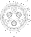
- the speed reducer 1 is an eccentric differential speed reducer including a pin gear as internal teeth and including trochoidal gears as external teeth.
- the speed reducer 1 includes the output section 2 having a cylindrical shape and a reduction mechanism 3 provided in the output section 2.
- the inner peripheral surface of the output section 2 has internal teeth 2H formed thereon.
- the internal teeth 2H are formed of a plurality of pins 2P shaped like a circular column and pin grooves 2M supporting the plurality of pins 2P.
- the plurality of pin grooves 2M have a substantially semicircular section and are arranged along the inner peripheral surface of the output section 2.
- the gear MG is located at the center of the three gears 5 so as to mesh with the three gears 5. Therefore, the three gears 5 rotate in conjunction with the rotation of the gear MG.
- Each of the gears 5 includes, for example, the spur gear 5G meshing with the gear MG, a shaft 5S coupled coaxially with the spur gear 5G, and a first eccentric cam 5M and a second eccentric cam 5N formed on the shaft 5S.
- the second eccentric cam 5N is formed eccentrically such that its central axis is off the axis 5L of the shaft 5S.
- the direction of eccentricity of the second eccentric cam 5N is opposite to that of the first eccentric cam 5M.
- the first eccentric cam 5M and the second eccentric cam 5N rotate in conjunction with the shaft 5S coupled to the spur gear 5G.
- the first eccentric cam 5M drives a first eccentric gear 6 disposed in the output section 2.
- the three second through-holes 6K are arranged symmetrically around the central axis 6L.
- Each of the second through-holes 6K has a thin portion 6P formed of a region having a smallest thickness between the second through-hole 6K and the external teeth 6C.
- the second eccentric cam 5N drives a second eccentric gear 7 disposed in the output section 2.
- the second eccentric gear 7 is shaped like a disc.
- the second eccentric gear 7 does not slide but rolls along the inner peripheral surface of the output section 2, with a part of the external teeth 7C meshing with the internal teeth 2H, and thus the second eccentric gear 7 rotates eccentrically.
- the second eccentric gear 7 rotates in conjunction with the first eccentric gear 6, and it rotates eccentrically with its direction of eccentricity being opposite to that of the first eccentric gear 6. Since the second eccentric gear 7 and the first eccentric gear 6 rotate in conjunction with each other, the rotational balance of the speed reducer 1 is maintained.
- the second eccentric gear 7 has, for example, three first through-holes 7H that rotatably support three second eccentric cams 5N, respectively. Each of the first through-holes 7H has a circular opening. Each of the second eccentric cam 5N is rotatably supported in the first through-hole 7H via a needle bearing B6.
- the second eccentric gear 7 has three second through-holes 7K disposed between the three first through-holes 7H. The number of the second through-holes 7K is determined in accordance with the number of the first through-holes 7H. For example, three or more second through-holes 7K may be provided.
- the three second through-holes 7K are arranged symmetrically around the central axis 7L.
- Each of the second through-holes 7K has a thin portion (not shown) formed of a region having a smallest thickness between the second through-hole 7K and the external teeth 7C.
- the first end SA of each of the coupling shafts S projects from the second through-holes 6K, 7K toward the second disc U2.
- the first end SA and the second end SB of the coupling shaft S have a circular section as viewed from the direction of the axis SL.
- the first end SA of the coupling shaft S is supported on the second disc U2.
- the second end SB of the coupling shaft S is supported on the first disc U1.
- the second end SB of the coupling shaft S is positioned on the first disc U1 by a pin SP. It is also possible that, as viewed in the direction of the axis SL, the first end SA of the coupling shaft S is positioned on the second disc U2 by a pin SP.
- the coupling shaft S is fixed to, for example, the fixing member 1F via the first disc U1. With this configuration, the first disc U1, the coupling shafts S, and the second disc U2 are fixed to the fixing member 1F.
- the output section 2 rotates relative to the first disc U1, the coupling shafts S, and the second disc U2. The output section 2 reduces the number of rotations and increases the torque as compared to the rotational power input to the spur gear 5G, and outputs the rotational force around the central axis L (rotational axis).
- the arm 30 connected to the output section 2 rotates about the central axis L (rotational axis) in conjunction with the rotation of the output section 2.
- the arm 30 is, for example, formed in a rod shape.
- a proximal end of the arm 30 is connected to, for example, the outer periphery of the output section 2.
- the arm 30 is coupled to the speed reducer 1 such that the arm 30 is rotatable about the central axis L.
- a ball joint (not shown) is provided on a distal end of the arm 30.
- the distal end of the arm 30 is connected to a steering mechanism (not shown).
- the connecting position of the arm 30 to the output section 2 is not limited to that in the embodiment.
- the arm 30 may be connected at any position around the central axis L (rotational axis), for example, depending on the position of the object connected to the distal end of the arm 30.
- the arm 30 is rotatable in the circumferential direction of the output section 2 of the speed reducer 1 with no limitation of the rotation range.
- the arm 30 can be connected to the output section 2 of the speed reducer 1 at any position in the circumferential direction of the output section 2.
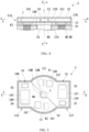
- control device C Next, a description is given of the control device C.
- the second control device C4 includes a second board C4K having a second circuit C4T provided thereon.
- the second board C4K is, for example, screwed to the casing C1.
- the second board C4K has, for example, a first surface facing the lid portion C2 and a second surface facing the bottom surface C1A.
- the second circuit C4T is provided on the first surface of the second board C4K.
- the motor M is controlled by the first control device C3 and the second control device C4 based on the sensing value obtained by a steering wheel angle sensor HS provided on the steering unit of the vehicle.
- the first control device C3 and the second control device C4 control the electric power supplied to the coil unit MU of the motor M to adjust the rotation of the rotor MR.
- the coil unit MU includes, for example: a first three-phase coil unit MU1 having a three-phase coil controlled by the first control device C3; and a second three-phase coil unit MU2 having a three-phase coil controlled by the second control device C4.
- the first three-phase coil unit MU1 and the second three-phase coil unit MU2 may be either separate from each other or combined into one three-phase coil unit.
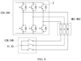
- the first control device C3 includes: the first inverter circuit C3I for supplying electric power to the first three-phase coil unit MU1; a first switching unit C3B for controlling the connection at a first connection unit X1 at which the terminals of the first three-phase coil unit MU1 are connected; and a first control unit C3A for controlling the first inverter circuit C3I and the first switching unit C3B.
- the first inverter circuit C3I is formed of, for example, a plurality of power transistor devices Z.
- the first switching unit C3B is formed of, for example, a plurality of power transistor devices (not shown).
- the first control unit C3A generates pulse current for the PWM (pulse width modulation) control on the timings of switching between On and Off states of each power transistor device Z in the first inverter circuit C3I, thereby controlling the first three-phase coil unit MU1.
- the first control unit C3A may control the first three-phase coil unit MU1 by any control methods other than the PWM control.
- the first control unit C3A puts the first switching unit C3B into the open state to stop the supply of electric power to the first three-phase coil unit MU1. This ensures the safety of the steering device W in the event of a malfunction.
- the second control device C4 includes: the second inverter circuit C4I for supplying electric power to the second three-phase coil unit MU2; a second switching unit C4B for controlling the connection at a second connection unit X2 at which the terminals of the second three-phase coil unit MU2 are connected; and a second control unit C4A for controlling the second inverter circuit C4I and the second switching unit C4B.
- the second inverter circuit C4I is formed of, for example, a plurality of power transistor devices Z.
- the second switching unit C4B is formed of, for example, a plurality of power transistor devices (not shown).
- the second control unit C4A generates pulse current for the PWM (pulse width modulation) control on the timings of switching between On and Off states of each power transistor device Z in the second inverter circuit C4I, thereby controlling the second three-phase coil unit MU2.
- the second control unit C4A may control the second three-phase coil unit MU2 by any control methods other than the PWM control.
- the second control unit C4A puts the second switching unit C4B into the open state to stop the supply of electric power to the second three-phase coil unit MU2. This ensures the safety of the steering device W in the event of a malfunction.
- the first control unit C3A controls 50% of the output of the motor M by controlling the first three-phase coil unit MU1.
- the second control unit C4A controls 50% of the output of the motor M by controlling the second three-phase coil unit MU2.
- the first control unit C3A may control 100% of the output of the motor M by controlling the first three-phase coil unit MU1. In this case, the second control unit C4A does not control the motor M.
- the second control unit C4A may control 100% of the output of the motor M by controlling the second three-phase coil unit MU2. In this case, the first control unit C3A does not control the motor M. With this configuration, if any one of the first control device C3 and the second control device C4 malfunctions, the steering device W maintains 100% of its output by switching to the other control device.
- the first eccentric gear 6 rotates eccentrically about the central axis L along the inner peripheral surface of the output section 2.
- the second eccentric gear 7 rotates eccentrically about the central axis L along the inner peripheral surface of the output section 2.
- the rotation of the second eccentric gear 7 is out of phase with the rotation of the first eccentric gear 6 by a half rotation.
- the first disc U1 and the second disc U2 rotate simultaneously about the central axis L relative to the output section 2.
- the first disc U1 and the second disc U2 are fixed to the fixing member 1F. Therefore, the output section 2 rotates about the central axis L relative to the first disc U1 and second disc U2. The number of rotations of the output section 2 is smaller than that of the shafts 5S.
- each coupling shaft S moves relatively along the shape of the inner periphery of the associated second through-hole 6K of the first eccentric gear 6, without contacting with the inner periphery of the second through-hole 6K.
- each coupling shaft S moves relatively along the shape of the inner periphery of the associated second through-hole 7K of the second eccentric gear 7, without contacting with the inner periphery of the second through-hole 7K.
- the eccentric movement of the first eccentric gear 6 and the second eccentric gear 7 causes the output section 2 to rotate about the central axis L relative to the first disc U1 and the second disc U2.
- the number of rotations of the output section 2 is smaller than that of the spur gears 5G. Therefore, when a rotation object that receives the rotational output is coupled to the output section 2, it receives a rotational output having a lower speed and a higher torque than the spur gears 5G. Further, the arm 30 rotates about the central axis L in conjunction with the rotation of the output section 2. At this time, the arm 30 rotates with no limitation on its rotation range.
- the rotational angle of the arm 30 is sensed by the angle sensing unit 40. Further, the control device C performs the semi-closed loop control in which the sensing value obtained by the angle sensing unit 40 is compared with an instruction signal for the rotational angle of the motor M in accordance with the rotational angle of the arm 30, thereby setting the deflection between the rotational angle of the arm 30 and the instruction signal for the rotational angle of the motor M at zero. In this manner, the rotational angle of the arm 30 can be adjusted accurately.
- the steering device W can realize the steer-by-wire system in which the rotational angle of the arm 30 is adjusted in accordance with the rotational angle in the operation of the steering wheel.
- the control device C, the motor M, and the speed reducer 1 are disposed coaxially with the central axis L. Therefore, the steering device W can have a smaller width along the direction of the central axis L, resulting in a smaller size of the steering device W.
- the gear MG is integrated with the distal end of the rotor output shaft MS of the motor M. Therefore, the steering device W can have a smaller width along the direction of the central axis L, resulting in a smaller size of the steering device W.
Landscapes
- Engineering & Computer Science (AREA)
- Mechanical Engineering (AREA)
- Chemical & Material Sciences (AREA)
- Combustion & Propulsion (AREA)
- Transportation (AREA)
- Power Engineering (AREA)
- General Engineering & Computer Science (AREA)
- Microelectronics & Electronic Packaging (AREA)
- Power Steering Mechanism (AREA)
- Motor Or Generator Frames (AREA)
- Connection Of Motors, Electrical Generators, Mechanical Devices, And The Like (AREA)
Claims (11)
- Lenkvorrichtung (W), aufweisend:ein Geschwindigkeitsreduzierer (1), der so konfiguriert ist, dass er eine von einer Oberflächenseite eingegebene Drehkraft verlangsamt, während er ein Drehmoment der Drehkraft und eine Ausgangsdrehung von einem auf der anderen Oberflächenseite angeordneten Ausgangsabschnitt (2) erhöht;einen Motor (M), der auf der einen Oberflächenseite vorgesehen und so konfiguriert ist, dass er die Drehkraft in den Geschwindigkeitsreduzierer (1) eingibt; undeine Steuervorrichtung (C), die so konfiguriert ist, dass sie den Motor (M) steuert,wobei der Geschwindigkeitsreduzierer (1) mit einer an einem Fahrzeug vorgesehenen Lenkeinheit verbunden ist, um zu bewirken, dass die Lenkeinheit ein Rad durch das Drehmoment lenkt,wobei der Motor (M) einen Rotor (MR) enthält, der so konfiguriert ist, dass er die Drehkraft erzeugt,wobei der Rotor (MR) eine Rotorausgangswelle (MS) enthält, die koaxial zu einer Ausgangsachse des Ausgangsabschnitts (2) angeordnet ist,wobei der Motor (M) die Drehleistung von einer Endseite der Rotorausgangswelle (MS) in den Geschwindigkeitsreduzierer (1) einspeist,wobei die Steuervorrichtung (C) auf der anderen Endseite der Rotorausgangswelle (MS) koaxial mit der Rotorausgangswelle (MS) angeordnet ist und eine Erfassungseinheit (CS) umfasst, die so konfiguriert ist, dass sie die Drehung des Rotors (MR) erfasst,wobei die Steuervorrichtung (C) beinhaltet:eine Wechselrichterschaltung (C3I, C4I), die so konfiguriert ist, dass sie einen elektrischen Strom zur Steuerung des Motors (M) erzeugt; undeine Kopplungseinheit (K1, K2), die eine elektrische Verbindung zwischen der Wechselrichterschaltung (C3I, C4I) und dem Motor (M) herstellt,wobei die Kopplungseinheit (K1, K2) benachbart zu der Wechselrichterschaltung (C3I, C4I) und so angeordnet ist, dass sie dem Motor (M) zugewandt ist, undwobei die Kopplungseinheit (K1, K2) ferner als eine Trägerstruktur konfiguriert ist, die eine Platine (C3K, C4K), auf der die Wechselrichterschaltung (C3I, C4I), die darauf vorgesehen ist, an einem Gehäuse (M2) des Motors (M) abnehmbar trägt,dadurch gekennzeichnet, dassder Ausgangsabschnitt (2) einen darauf vorgesehenen Arm (30) aufweist, der so konfiguriert ist, dass er sich um die Ausgangsachse in einer Umfangsrichtung des Ausgangsabschnitts (2) dreht, undder Arm (30) so konfiguriert ist, dass er so angeordnet ist, dass er von dem Ausgangsabschnitt (2) in einer radialen Richtung orthogonal zu der Ausgangsachse vorsteht, und dass er mit der Lenkeinheit verbunden ist.
- Lenkvorrichtung nach Anspruch 1, wobei die eine Endseite der Rotorausgangswelle (MS) ein darin integriertes Zahnrad (MG) aufweist, das dazu dient, die Drehkraft in den Geschwindigkeitsreduzierer (1) einzuleiten.
- Lenkvorrichtung (W) nach Anspruch 1,wobei die Steuervorrichtung (C) eine erste Steuervorrichtung (C3) und eine zweite Steuervorrichtung (C4) zur Steuerung des Motors (M) aufweist, undwobei die erste Steuervorrichtung (C3) und die zweite Steuervorrichtung (C4) aus einer Richtung entlang der Rotorausgangswelle (MS) gesehen punktsymmetrisch angeordnet sind.
- Lenkvorrichtung (W) nach Anspruch 3,wobei sowohl die erste Steuervorrichtung (C3) als auch die zweite Steuervorrichtung (C4) einen Vorsprung (C1P, C1Q) aufweist, der von dem Motor (M) aus gesehen in Richtung entlang der Rotorausgangswelle (MS) radial nach außen ragt, undwobei ein Abschnitt jedes der Vorsprünge (C1P, C1Q), der dem Motor (M) zugewandt ist, einen darauf vorgesehenen Verbinder (Dn) aufweist, der mit einer anderen Vorrichtung elektrisch verbunden ist.
- Lenkvorrichtung (W) nach Anspruch 4,wobei die Verbinder (Dn) zumindest Stromversorgungsverbinder (D1, D2) umfassen, die so konfiguriert sind, dass sie den Motor (M) mit elektrischem Strom versorgen, undwobei die Stromversorgungsverbinder (D1, D2) an dem Vorsprung (C1P) der ersten Steuervorrichtung (C3) und dem Vorsprung (C1Q) der zweiten Steuervorrichtung (C4) vorgesehen sind und voneinander beabstandet sind.
- Lenkvorrichtung (W) nach Anspruch 1, wobei eine Winkelerfassungseinheit (40), die zum Erfassen eines Drehwinkels des Arms (30) konfiguriert ist, zwischen dem Arm (30) und dem Motor (M) vorgesehen ist.
- Lenkvorrichtung (W) nach Anspruch 6, wobei sich die Winkelerfassungseinheit (40) entlang der Umfangsrichtung des Ausgangsabschnitts (2) erstreckt.
- Lenkvorrichtung (W) nach Anspruch 1, wobei der Geschwindigkeitsreduzierer (1) eine Rotationserfassungseinheit (50) zum Erfassen der Rotation einer Kurbelwelle (5S) enthält, die den Rotationsleistungseingang von der Rotorausgangswelle (MS) empfängt, und wobei die Steuervorrichtung (C) einen Rotationswinkel des Arms (30) basierend auf einem Rotationserfassungswert, der von der Rotationserfassungseinheit (50) erhalten wird, und einem Untersetzungsverhältnis des Geschwindigkeitsreduzierers (1) einstellt.
- Lenkvorrichtung (W) nach Anspruch 1, wobei die Steuervorrichtung (C) einen Drehwinkel des Arms (30) auf der Grundlage eines von der Abtasteinheit (CS) erhaltenen Abtastwerts und eines Untersetzungsverhältnisses des Geschwindigkeitsreduzierers (1) einstellt.
- Lenkvorrichtung (W) nach Anspruch 1,wobei die Steuervorrichtung (C) eine erste Steuervorrichtung (C3) und eine zweite Steuervorrichtung (C4) umfasst, die so konfiguriert sind, dass sie den Motor (M) steuern, undwobei der Motor (M) eine erste Drehstromspuleneinheit (MU1) umfasst, die von der ersten Steuervorrichtung (C3) gesteuert wird, und eine zweite Drehstromspuleneinheit (MU2), die von der zweiten Steuervorrichtung (C4) gesteuert wird.
- Lenkvorrichtung (W) nach Anspruch 10,wobei die erste Steuervorrichtung (C3) eine erste Schalteinheit (C3B) umfasst, die so konfiguriert ist, dass sie die Verbindung an einer ersten Verbindungseinheit (X1) steuert, an der Anschlüsse der ersten Drehstromspuleneinheit (MU1) angeschlossen sind, undwobei die zweite Steuervorrichtung (C4) eine zweite Schalteinheit (C4B) umfasst, die so konfiguriert ist, dass sie die Verbindung an einer zweiten Verbindungseinheit (X2) steuert, an der Anschlüsse der zweiten Drehstromspuleneinheit (MU2) angeschlossen sind.
Applications Claiming Priority (1)
| Application Number | Priority Date | Filing Date | Title |
|---|---|---|---|
| JP2021073445A JP7021383B1 (ja) | 2021-04-23 | 2021-04-23 | 操舵装置 |
Publications (2)
| Publication Number | Publication Date |
|---|---|
| EP4087376A1 EP4087376A1 (de) | 2022-11-09 |
| EP4087376B1 true EP4087376B1 (de) | 2025-07-09 |
Family
ID=80948536
Family Applications (1)
| Application Number | Title | Priority Date | Filing Date |
|---|---|---|---|
| EP22169018.3A Active EP4087376B1 (de) | 2021-04-23 | 2022-04-20 | Lenkvorrichtung |
Country Status (4)
| Country | Link |
|---|---|
| US (2) | US11661104B2 (de) |
| EP (1) | EP4087376B1 (de) |
| JP (1) | JP7021383B1 (de) |
| CN (2) | CN116946243A (de) |
Family Cites Families (24)
| Publication number | Priority date | Publication date | Assignee | Title |
|---|---|---|---|---|
| CN100582800C (zh) * | 2004-09-02 | 2010-01-20 | 东京毅力科创株式会社 | 重物翻转设备 |
| JP4853070B2 (ja) * | 2005-05-26 | 2012-01-11 | 日本精工株式会社 | ステアバイワイヤシステム |
| JP4887778B2 (ja) * | 2005-12-27 | 2012-02-29 | 富士通株式会社 | コネクタの挿抜機構 |
| JP2008305747A (ja) * | 2007-06-11 | 2008-12-18 | Molex Japan Co Ltd | コネクタ並びにその支持装置及び方法 |
| JP2010225351A (ja) * | 2009-03-23 | 2010-10-07 | Sony Corp | コネクター付き装置の検査方法、コネクター付き装置の製造方法、およびコネクター付き装置用検査装置 |
| JP6123848B2 (ja) | 2014-07-31 | 2017-05-10 | 株式会社デンソー | 駆動装置、および、これを用いた電動パワーステアリング装置 |
| KR101595722B1 (ko) | 2014-11-11 | 2016-02-22 | 현대모비스 주식회사 | 차량 조향용 구동장치 |
| JP5951067B1 (ja) | 2015-04-10 | 2016-07-13 | 三菱電機株式会社 | 電動パワーステアリング装置 |
| DE102015217045A1 (de) | 2015-09-07 | 2017-03-09 | Volkswagen Aktiengesellschaft | Nutzfahrzeuglenkung |
| JP6648492B2 (ja) * | 2015-11-04 | 2020-02-14 | 株式会社デンソー | 電子装置 |
| JP2017109599A (ja) * | 2015-12-16 | 2017-06-22 | ナブテスコ株式会社 | 操舵補助装置 |
| JP6681201B2 (ja) * | 2016-01-22 | 2020-04-15 | ナブテスコ株式会社 | 操舵装置 |
| JP6654445B2 (ja) * | 2016-01-22 | 2020-02-26 | ナブテスコ株式会社 | 操舵装置 |
| US10906577B2 (en) * | 2016-04-06 | 2021-02-02 | Mitsubishi Electric Corporation | Electric power steering apparatus |
| EP3508398B1 (de) * | 2016-09-05 | 2020-04-29 | Mitsubishi Electric Corporation | Elektrische servolenkvorrichtung |
| JP6702212B2 (ja) * | 2017-01-31 | 2020-05-27 | 株式会社デンソー | 駆動装置 |
| CN110521093B (zh) | 2017-03-31 | 2021-08-31 | 日本电产株式会社 | 马达以及电动助力转向装置 |
| JP7161846B2 (ja) | 2017-11-21 | 2022-10-27 | ナブテスコ株式会社 | 操舵装置 |
| JP6954817B2 (ja) * | 2017-11-30 | 2021-10-27 | ナブテスコ株式会社 | 補助装置 |
| CN111557075B (zh) * | 2018-01-10 | 2024-03-08 | 日本电产株式会社 | 电力转换装置、马达模块以及电动助力转向装置 |
| JP2019156042A (ja) * | 2018-03-09 | 2019-09-19 | 住友重機械工業株式会社 | 操舵補助装置 |
| DE112019001277T5 (de) * | 2018-03-13 | 2021-04-01 | Hitachi Automotive Systems, Ltd. | Steuerungsvorrichtung für bordeigene vorrichtung |
| EP3843250A4 (de) * | 2018-08-24 | 2021-08-18 | Mitsubishi Electric Corporation | Elektrische servolenkvorrichtung |
| DE102018129061A1 (de) | 2018-11-19 | 2020-05-20 | Trw Automotive Gmbh | Verfahren zur Herstellung von elektromotorisch unterstützten Lenksystemen sowie elektromotorisch unterstütztes Lenksystem |
-
2021
- 2021-04-23 JP JP2021073445A patent/JP7021383B1/ja active Active
-
2022
- 2022-04-18 US US17/722,837 patent/US11661104B2/en active Active
- 2022-04-20 EP EP22169018.3A patent/EP4087376B1/de active Active
- 2022-04-22 CN CN202310928486.4A patent/CN116946243A/zh active Pending
- 2022-04-22 CN CN202210430213.2A patent/CN115230802B/zh active Active
-
2023
- 2023-04-11 US US18/298,476 patent/US12116050B2/en active Active
Also Published As
| Publication number | Publication date |
|---|---|
| JP7021383B1 (ja) | 2022-02-16 |
| US20220340196A1 (en) | 2022-10-27 |
| CN115230802B (zh) | 2023-08-11 |
| CN116946243A (zh) | 2023-10-27 |
| US20230303157A1 (en) | 2023-09-28 |
| US12116050B2 (en) | 2024-10-15 |
| JP2022167573A (ja) | 2022-11-04 |
| CN115230802A (zh) | 2022-10-25 |
| EP4087376A1 (de) | 2022-11-09 |
| US11661104B2 (en) | 2023-05-30 |
Similar Documents
| Publication | Publication Date | Title |
|---|---|---|
| JP5252939B2 (ja) | モータ制御装置およびこれを備える車両用操舵装置 | |
| EP1880922A2 (de) | Elektrische Servolenkung | |
| US11904958B2 (en) | Detection device, calculation device, control device, and electric power steering device using the same | |
| JPWO2014054265A1 (ja) | ステアリング制御装置、ステアリング制御方法 | |
| CN109428407B (zh) | 定子芯 | |
| JP2020060476A (ja) | 回転検出装置、操舵システム | |
| US11469700B2 (en) | Motor and electric power steering device | |
| JP5785309B2 (ja) | 電動パワーステアリング装置 | |
| JP5563513B2 (ja) | 電動パワーステアリング装置 | |
| JP2020060477A (ja) | 回転検出装置、操舵システム | |
| EP4087376B1 (de) | Lenkvorrichtung | |
| US11981375B2 (en) | Steering device | |
| JP2020097973A (ja) | ディスクブレーキ装置 | |
| JP2004182061A (ja) | 車両用操舵装置 | |
| US11243128B2 (en) | Sensor capable of ensuring that a sensor housing has sufficient rigidity | |
| JP2012010465A (ja) | モータ制御装置及び車両用操舵装置 | |
| JP6059771B2 (ja) | 電動パワーステアリング装置 | |
| JP2009071953A (ja) | 駆動装置 | |
| US20250018998A1 (en) | Dual motor handwheel actuator assembly | |
| JP2020001557A (ja) | パワーステアリング装置 | |
| JP6248173B2 (ja) | 電動パワーステアリング装置 | |
| JP2005199937A (ja) | ステアリング操作装置 | |
| JP2016130081A (ja) | パワーステアリング装置 | |
| KR20230001214A (ko) | 차량용 조향장치 | |
| JP3477886B2 (ja) | 電動式パワーステアリング装置 |
Legal Events
| Date | Code | Title | Description |
|---|---|---|---|
| PUAI | Public reference made under article 153(3) epc to a published international application that has entered the european phase |
Free format text: ORIGINAL CODE: 0009012 |
|
| STAA | Information on the status of an ep patent application or granted ep patent |
Free format text: STATUS: REQUEST FOR EXAMINATION WAS MADE |
|
| 17P | Request for examination filed |
Effective date: 20220420 |
|
| AK | Designated contracting states |
Kind code of ref document: A1 Designated state(s): AL AT BE BG CH CY CZ DE DK EE ES FI FR GB GR HR HU IE IS IT LI LT LU LV MC MK MT NL NO PL PT RO RS SE SI SK SM TR |
|
| RBV | Designated contracting states (corrected) |
Designated state(s): AL AT BE BG CH CY CZ DE DK EE ES FI FR GB GR HR HU IE IS IT LI LT LU LV MC MK MT NL NO PL PT RO RS SE SI SK SM TR |
|
| P01 | Opt-out of the competence of the unified patent court (upc) registered |
Effective date: 20230523 |
|
| GRAP | Despatch of communication of intention to grant a patent |
Free format text: ORIGINAL CODE: EPIDOSNIGR1 |
|
| STAA | Information on the status of an ep patent application or granted ep patent |
Free format text: STATUS: GRANT OF PATENT IS INTENDED |
|
| INTG | Intention to grant announced |
Effective date: 20250213 |
|
| GRAS | Grant fee paid |
Free format text: ORIGINAL CODE: EPIDOSNIGR3 |
|
| GRAA | (expected) grant |
Free format text: ORIGINAL CODE: 0009210 |
|
| STAA | Information on the status of an ep patent application or granted ep patent |
Free format text: STATUS: THE PATENT HAS BEEN GRANTED |
|
| AK | Designated contracting states |
Kind code of ref document: B1 Designated state(s): AL AT BE BG CH CY CZ DE DK EE ES FI FR GB GR HR HU IE IS IT LI LT LU LV MC MK MT NL NO PL PT RO RS SE SI SK SM TR |
|
| REG | Reference to a national code |
Ref country code: GB Ref legal event code: FG4D |
|
| REG | Reference to a national code |
Ref country code: CH Ref legal event code: EP |
|
| REG | Reference to a national code |
Ref country code: IE Ref legal event code: FG4D |
|
| REG | Reference to a national code |
Ref country code: DE Ref legal event code: R096 Ref document number: 602022017176 Country of ref document: DE |
|
| REG | Reference to a national code |
Ref country code: NL Ref legal event code: FP |
|
| REG | Reference to a national code |
Ref country code: SE Ref legal event code: TRGR |
|
| PG25 | Lapsed in a contracting state [announced via postgrant information from national office to epo] |
Ref country code: PT Free format text: LAPSE BECAUSE OF FAILURE TO SUBMIT A TRANSLATION OF THE DESCRIPTION OR TO PAY THE FEE WITHIN THE PRESCRIBED TIME-LIMIT Effective date: 20251110 |
|
| REG | Reference to a national code |
Ref country code: AT Ref legal event code: MK05 Ref document number: 1813107 Country of ref document: AT Kind code of ref document: T Effective date: 20250709 |