EP4072897B1 - Fahrzeugsitz - Google Patents
Fahrzeugsitz Download PDFInfo
- Publication number
- EP4072897B1 EP4072897B1 EP20824196.8A EP20824196A EP4072897B1 EP 4072897 B1 EP4072897 B1 EP 4072897B1 EP 20824196 A EP20824196 A EP 20824196A EP 4072897 B1 EP4072897 B1 EP 4072897B1
- Authority
- EP
- European Patent Office
- Prior art keywords
- vehicle seat
- panel
- use position
- locking device
- contact element
- Prior art date
- Legal status (The legal status is an assumption and is not a legal conclusion. Google has not performed a legal analysis and makes no representation as to the accuracy of the status listed.)
- Active
Links
Images

Classifications
-
- B—PERFORMING OPERATIONS; TRANSPORTING
- B60—VEHICLES IN GENERAL
- B60N—SEATS SPECIALLY ADAPTED FOR VEHICLES; VEHICLE PASSENGER ACCOMMODATION NOT OTHERWISE PROVIDED FOR
- B60N2/00—Seats specially adapted for vehicles; Arrangement or mounting of seats in vehicles
- B60N2/005—Arrangement or mounting of seats in vehicles, e.g. dismountable auxiliary seats
- B60N2/015—Attaching seats directly to vehicle chassis
- B60N2/01508—Attaching seats directly to vehicle chassis using quick release attachments
- B60N2/01516—Attaching seats directly to vehicle chassis using quick release attachments with locking mechanisms
- B60N2/01583—Attaching seats directly to vehicle chassis using quick release attachments with locking mechanisms locking on transversal elements on the vehicle floor or rail, e.g. transversal rods
-
- B—PERFORMING OPERATIONS; TRANSPORTING
- B60—VEHICLES IN GENERAL
- B60N—SEATS SPECIALLY ADAPTED FOR VEHICLES; VEHICLE PASSENGER ACCOMMODATION NOT OTHERWISE PROVIDED FOR
- B60N2/00—Seats specially adapted for vehicles; Arrangement or mounting of seats in vehicles
- B60N2/02—Seats specially adapted for vehicles; Arrangement or mounting of seats in vehicles the seat or part thereof being movable, e.g. adjustable
- B60N2/0224—Non-manual adjustments, e.g. with electrical operation
- B60N2/02246—Electric motors therefor
-
- B—PERFORMING OPERATIONS; TRANSPORTING
- B60—VEHICLES IN GENERAL
- B60N—SEATS SPECIALLY ADAPTED FOR VEHICLES; VEHICLE PASSENGER ACCOMMODATION NOT OTHERWISE PROVIDED FOR
- B60N2/00—Seats specially adapted for vehicles; Arrangement or mounting of seats in vehicles
- B60N2/02—Seats specially adapted for vehicles; Arrangement or mounting of seats in vehicles the seat or part thereof being movable, e.g. adjustable
- B60N2/0224—Non-manual adjustments, e.g. with electrical operation
- B60N2/0244—Non-manual adjustments, e.g. with electrical operation with logic circuits
- B60N2/0268—Non-manual adjustments, e.g. with electrical operation with logic circuits using sensors or detectors for adapting the seat or seat part, e.g. to the position of an occupant
-
- B—PERFORMING OPERATIONS; TRANSPORTING
- B60—VEHICLES IN GENERAL
- B60N—SEATS SPECIALLY ADAPTED FOR VEHICLES; VEHICLE PASSENGER ACCOMMODATION NOT OTHERWISE PROVIDED FOR
- B60N2/00—Seats specially adapted for vehicles; Arrangement or mounting of seats in vehicles
- B60N2/02—Seats specially adapted for vehicles; Arrangement or mounting of seats in vehicles the seat or part thereof being movable, e.g. adjustable
- B60N2/04—Seats specially adapted for vehicles; Arrangement or mounting of seats in vehicles the seat or part thereof being movable, e.g. adjustable the whole seat being movable
- B60N2/12—Seats specially adapted for vehicles; Arrangement or mounting of seats in vehicles the seat or part thereof being movable, e.g. adjustable the whole seat being movable slidable and tiltable
-
- B—PERFORMING OPERATIONS; TRANSPORTING
- B60—VEHICLES IN GENERAL
- B60N—SEATS SPECIALLY ADAPTED FOR VEHICLES; VEHICLE PASSENGER ACCOMMODATION NOT OTHERWISE PROVIDED FOR
- B60N2/00—Seats specially adapted for vehicles; Arrangement or mounting of seats in vehicles
- B60N2/58—Seat coverings
- B60N2/60—Removable protective coverings
- B60N2/6009—Removable protective coverings covering more than only the seat
-
- B—PERFORMING OPERATIONS; TRANSPORTING
- B60—VEHICLES IN GENERAL
- B60N—SEATS SPECIALLY ADAPTED FOR VEHICLES; VEHICLE PASSENGER ACCOMMODATION NOT OTHERWISE PROVIDED FOR
- B60N2/00—Seats specially adapted for vehicles; Arrangement or mounting of seats in vehicles
- B60N2/005—Arrangement or mounting of seats in vehicles, e.g. dismountable auxiliary seats
- B60N2002/0055—Arrangement or mounting of seats in vehicles, e.g. dismountable auxiliary seats characterised by special measures to ensure that no seat or seat part collides, during its movement, with other seats, seat parts or the vehicle itself
-
- B—PERFORMING OPERATIONS; TRANSPORTING
- B60—VEHICLES IN GENERAL
- B60N—SEATS SPECIALLY ADAPTED FOR VEHICLES; VEHICLE PASSENGER ACCOMMODATION NOT OTHERWISE PROVIDED FOR
- B60N2210/00—Sensor types, e.g. for passenger detection systems or for controlling seats
- B60N2210/40—Force or pressure sensors
- B60N2210/46—Electric switches
Definitions
- the invention relates to a vehicle seat, in particular a motor vehicle seat, with a seat part, a backrest, and a kinematics for transferring the vehicle seat from a position of use suitable for transporting people into a non-use position, in particular into an entry position that facilitates entry into a rear row of seats, wherein the vehicle seat can be transferred by means of a drive device from the position of use into the non-use position and vice versa (i.e. from the non-use position back into the position of use), wherein the vehicle seat has a rear foot with a locking device for securing it in the position of use, which can be locked with a counter element.
- a vehicle seat which can be moved from at least one position of use suitable for transporting people into a forward pivoted entry position and alternatively into a lowered floor position.
- the vehicle seat comprises a base, a swing arm which is hinged to a front foot attached to the base, a seat cushion support from which an arm protrudes at the rear, at the end of which a joint is arranged, two links which are at least indirectly hinged to the front foot attached to the base, a rear foot which is hinged to the links and is releasably locked to the base, and a backrest which is hinged to the rear foot by means of at least one lockable fitting about a backrest pivot axis.
- the vehicle seat has a protective device for detecting an obstacle in a path of movement of the rear foot when transferring the vehicle seat from the non-use position into the entry position, wherein the protective device has a panel with an opening which, when the panel is mounted, is aligned with a receiving opening of the locking device, so that the counter element can be inserted through the opening into the receiving opening of the locking device.
- a non-use position in the sense of the invention can be an entry position, in particular an easy-entry position in which the vehicle seat is pivoted forward, or a loading position in which the vehicle seat is swiveled forward to maximize storage space.
- the protective device has a cover.
- the cover can serve to cover the rear foot, in particular in the area of the locking device.
- the cover can have two parallel wall sections.
- the cover has an opening. When the cover is mounted, the opening is aligned with the receiving opening of the locking device, so that the counter element can be inserted through the opening into the receiving opening of the locking device.
- the counter element can be a bolt.
- a touch element is arranged on at least one edge section of the opening.
- the touch element can be attached to the panel in a limited, in particular slightly, pivotable manner.
- the touch element can be attached to the panel by means of a hinge, in particular by means of a film hinge.
- the touch element can be mounted on the panel in a linearly movable manner.
- the touch element can act on a switch when the touch element moves, in particular pivots, from a normal position.
- the switch can be arranged on an inner side of the wall section of the panel.
- the touch element of the panel mounted on the rear foot can be arranged in the region of the locking device, in particular in the region of the receiving opening of the locking device.
- the touch element is designed to protrude from an outer surface of the panel.
- the touch element is preferably designed to protrude from an outer surface of the panel in a vertical direction.
- the sensor element can be used to detect an obstacle between the locking device and the counter element when the vehicle seat is being moved from the entry position to the use position.
- the obstacle can be a bag, a shoe belonging to a passenger in a rear row of seats, or another item of transport that has been placed in the footwell of the rear row of seats.
- the button element can act on the switch, which in turn acts on a drive device for pivoting the vehicle seat and stops the transfer of the vehicle seat into the use position. If necessary, if the transfer of the vehicle seat into the use position is stopped due to a detected obstacle, it can be triggered that the vehicle seat is returned to the entry position.
- a longitudinal direction x runs largely horizontally and preferably parallel to a vehicle longitudinal direction that corresponds to the normal direction of travel of the vehicle.
- a transverse direction y that runs perpendicular to the longitudinal direction x is also aligned horizontally in the vehicle and runs parallel to a vehicle transverse direction.
- a vertical direction z runs perpendicular to the longitudinal direction x and perpendicular to the transverse direction y.
- the vertical direction z runs parallel to the vehicle's vertical axis.
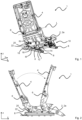
- the position and direction information used refer to a viewing direction of an occupant sitting in the vehicle seat 1 in a normal sitting position, wherein the vehicle seat 1 is installed in the vehicle, in a position of use suitable for the transport of persons with the backrest 4 in an upright position and aligned in the direction of travel as usual.
- a front foot 12 is attached to the base and is in this case firmly connected to the seat rail.
- the front foot 12 can also be releasably locked to the base, in particular the seat rail.
- the vehicle seat 1 is rotated around the four-bar arrangement along a predetermined path of movement from the position of use, according to the Fig. 2 vehicle seat 1 shown on the left, into the entry position, according to the Fig. 2 vehicle seat 1 shown superimposed on the right, and back from the entry position into the use position.
- a drive device is preferably provided for transferring the vehicle seat 1 from the use position into the entry position and back.
- the drive device is preferably electronically controlled.
- a rear foot 18, which is designed separately from the front foot 12, is arranged on the base in the longitudinal direction x behind the front foot 12.
- the rear foot 18 of the left side of the vehicle seat is connected to the rear foot 18 of the right side of the vehicle seat via a cross connection.
- the rear foot 18 of the left side of the vehicle seat is largely mirror-symmetrical to the rear foot 18 of the right side of the vehicle seat, so that only one rear foot 18 is described below.
- the rear foot 18 can be releasably locked to the base by means of a locking device 20 arranged on the rear foot 18. more precisely with a counter element 22 fixed to the base, in this case a bolt attached to the seat rail, and can thus be indirectly connected to the vehicle structure.
- the counter element 22 is centered in a slot-like receiving opening of the rear foot 18 or alternatively a housing of the locking device 20 in a locked state with the locking device 20 and is prevented from leaving the receiving opening by a latch of the locking device 20.
- the receiving opening has a V-shaped contour and is open in the direction of the base. The receiving opening tapers in a direction oriented away from the base. In the use position of the vehicle seat 1, the receiving opening and the latch of the locking device 20 fix the rear foot 18 relative to the base.
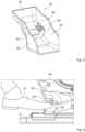
- Fig. 3 shows a protective device 30, having a cover 32.
- the cover 32 serves to cover the rear foot 18 in the area of the locking device 20.
- the cover 32 has two, in particular parallel oriented, wall sections 34.
- the cover 32 has an opening 36. In an assembled state of the cover 32, the opening 36 is aligned with the receiving opening of the locking device 20 such that the counter element 22 can be inserted through the opening 36 into the receiving opening of the locking device 20.
- a touch element 40 is arranged on at least one edge section of the opening 36.
- the touch element 40 is attached to the cover 32 in a limited pivoting manner.
- the touch element 40 is preferably attached to the cover 32 by means of a hinge, in particular a film hinge. When pivoting from a normal position of the pushbutton element 40, it acts on a switch 38 which is arranged on an inner side of the wall section 34.
- the Figures 5 and 6 show the vehicle seat 1 in the area of the protective device 30 during the transfer of the vehicle seat 1 from the entry position to the use position, shortly before reaching the use position.
- Fig. 6 the vehicle seat 1 has moved a little further in the direction of the use position.
- the touch element 40 has come into contact with the obstacle H located in the path of movement of the rear foot 18 of the vehicle seat 1.
- the obstacle H is arranged between the counter element 22 and the touch element 40 and the touch element 40 has been pivoted out of the normal position of the touch element 40 by the continued movement of the vehicle seat 1 in the direction of the use position.
- the touch element 40 therefore acts on the switch 38, which in turn acts on a drive device for pivoting the vehicle seat 1 in such a way that the transfer of the vehicle seat 1 into the use position stops and thus avoids a trapping situation in which a high force would act on the obstacle H. If necessary, a return transfer of the vehicle seat 1 into the entry position can be triggered.
Landscapes
- Engineering & Computer Science (AREA)
- Aviation & Aerospace Engineering (AREA)
- Transportation (AREA)
- Mechanical Engineering (AREA)
- Seats For Vehicles (AREA)
Description
- Die Erfindung betrifft einen Fahrzeugsitz, insbesondere Kraftfahrzeugsitz, mit einem Sitzteil, einer Lehne, und einer Kinematik zur Überführung des Fahrzeugsitzes von einer zur Personenbeförderung geeigneten Gebrauchsstellung in eine Nichtgebrauchsstellung, insbesondere in eine den Einstieg in eine hintere Sitzreihe erleichternde Einstiegsstellung, wobei der Fahrzeugsitz mittels einer Antriebsvorrichtung von der Gebrauchsstellung in die Nichtgebrauchsstellung und umgekehrt (das heißt von der Nichtgebrauchsstellung zurück in die Gebrauchsstellung) überführbar ist, wobei der Fahrzeugsitz zur Sicherung in der Gebrauchsstellung einen hinteren Fuß mit einer Verriegelungsvorrichtung aufweist, welche mit einem Gegenelement verriegelbar ist.
- Aus der
DE 10 2008 050 468 B3 ist ein Fahrzeugsitz bekannt, der von wenigstens einer zur Personenbeförderung geeigneten Gebrauchsstellung in eine vorgeschwenkte Einstiegsstellung und alternativ in eine abgesenkte Bodenstellung überführbar ist. Der Fahrzeugsitz umfasst eine Basis, eine Schwinge, die an einem an der Basis angebrachten vorderen Fuß angelenkt ist, einen Sitzkissenträger, von dem hinten ein Arm absteht, an dessen Ende ein Gelenk angeordnet ist, zwei Lenker, die wenigstens mittelbar an dem an der Basis angebrachten vorderen Fuß angelenkt sind, einen hinteren Fuß, der an den Lenkern angelenkt ist und mit der Basis lösbar verriegelt ist, und eine Lehne, die mittels wenigstens eines verriegelbaren Beschlags um eine Lehnenschwenkachse schwenkbar am hinteren Fuß angelenkt ist. Der Sitzkissenträger ist mittels des versetzt zur Lehnenschwenkachse mit dazu paralleler Schwenkachse angeordneten Gelenks an der Lehne angelenkt, wobei beim Übergang des Fahrzeugsitzes in die Einstiegsstellung der hintere Fuß entriegelt und sich mittels der beiden Lenker von der Basis entfernt und dabei das hintere Ende des Sitzkissens anhebt, während die Lehne unter Beibehaltung ihrer Neigung relativ zum hinteren Fuß vorschwenkt, und wobei die Schwinge nach vorne schwenkt und das vordere Ende des Sitzkissens absenkt. - Die
US 2016/318424 A1 offenbart einen Fahrzeugsitz mit einem Sitzteil, einer Lehne, und einer Kinematik zur Überführung des Fahrzeugsitzes von einer zur Personenbeförderung geeigneten Gebrauchsstellung in eine Einstiegsstellung, wobei der Fahrzeugsitz mittels einer Antriebsvorrichtung von der Gebrauchsstellung in die Nichtgebrauchsstellung und umgekehrt überführbar ist, wobei der Fahrzeugsitz zur Sicherung in der Gebrauchsstellung einen hinteren Fuß mit einer Verriegelungsvorrichtung aufweist, welche mit einem Gegenelement verriegelbar ist. Der Fahrzeugsitz weist eine Schutzvorrichtung zur Erfassung eines Hindernisses in einer Bewegungsbahn des hinteren Fußes bei der Überführung des Fahrzeugsitzes von der Nichtgebrauchsstellung in die Einstiegsstellung auf, wobei die Schutzvorrichtung eine Blende mit einer Öffnung aufweist, welche, in montiertem Zustand der Blende, an einer Aufnahmeöffnung der Verriegelungsvorrichtung ausgerichtet ist, so dass das Gegenelement durch die Öffnung hindurch in die Aufnahmeöffnung der Verriegelungsvorrichtung einführbar ist. - Der Erfindung liegt die Aufgabe zu Grunde, einen Fahrzeugsitz eingangs genannter Art zu verbessern, insbesondere einen Fahrzeugsitz mit einem Einklemmschutz zur sicheren Vermeidung eines Einklemmfalls bereitzustellen.
- Diese Aufgabe wird erfindungsgemäß gelöst, durch einen Fahrzeugsitz, insbesondere Kraftfahrzeugsitz, mit einem Sitzteil, einer Lehne, und einer Kinematik zur Überführung des Fahrzeugsitzes von einer zur Personenbeförderung geeigneten Gebrauchsstellung in eine Nichtgebrauchsstellung, insbesondere in eine den Einstieg in eine hintere Sitzreihe erleichternde Einstiegsstellung, wobei der Fahrzeugsitz mittels einer Antriebsvorrichtung von der Gebrauchsstellung in die Nichtgebrauchsstellung und umgekehrt überführbar ist, wobei der Fahrzeugsitz zur Sicherung in der Gebrauchsstellung einen hinteren Fuß mit einer Verriegelungsvorrichtung aufweist, welche mit einem Gegenelement verriegelbar ist, wobei der Fahrzeugsitz eine Schutzvorrichtung, insbesondere eine im Bereich der Verriegelungsvorrichtung angeordnete Schutzvorrichtung, zur Erfassung eines Hindernisses in einer Bewegungsbahn des hinteren Fußes bei der Überführung des Fahrzeugsitzes von der Nichtgebrauchsstellung in die Gebrauchsstellung aufweist.
- Dadurch, dass der Fahrzeugsitz eine Schutzvorrichtung zur Erfassung eines Hindernisses in einer Bewegungsbahn des hinteren Fußes bei der Überführung des Fahrzeugsitzes von der Nichtgebrauchsstellung in die Gebrauchsstellung aufweist, kann ein Vorhandensein eines Hindernisses, insbesondere zwischen dem hinteren Fuß und dem Gegenelement, rechtzeitig erkannt werden und durch Stoppen der Überführung des Fahrzeugsitzes zurück in die Gebrauchsstellung eine Beschädigung des Hindernisses, insbesondere eines Transportguts, oder ein Einklemmen des Hindernisses, insbesondere eines Körperteils, beispielsweise eines Fußes, eines Insassen einer hinteren Sitzreihe, verhindert werden. Vorzugsweise ist die Schutzvorrichtung im Bereich der Verriegelungsvorrichtung angeordnet. Die Schutzvorrichtung kann an der Verriegelungsvorrichtung befestigt sein. Die Schutzvorrichtung kann den hinteren Fuß im Bereich der Verriegelungsvorrichtung abdecken.
- Unter einer Nichtgebrauchsstellung im Sinne der Erfindung, kann eine Einstiegsstellung, insbesondere eine Easy-Entry-Stellung, in welcher der Fahrzeugsitz nach vorne verschwenkt ist, oder auch eine Ladestellung, in welcher der Fahrzeugsitz zur Maximierung eines Stauraums nach vorne verschwenkt ist, gemeint sein.
- Die Schutzvorrichtung weist eine Blende auf. Die Blende kann der Abdeckung des hinteren Fußes, insbesondere im Bereich der Verriegelungsvorrichtung, dienen. Die Blende kann zwei parallel orientiere Wandabschnitte aufweisen. Die Blende weist eine Öffnung auf. Die Öffnung ist, in montiertem Zustand der Blende, an der Aufnahmeöffnung der Verriegelungsvorrichtung ausgerichtet, so dass das Gegenelement durch die Öffnung hindurch in die Aufnahmeöffnung der Verriegelungsvorrichtung einführbar ist. Das Gegenelement kann ein Bolzen sein.
- An wenigstens einem Randabschnitt der Öffnung ist ein Tastelement angeordnet. Das Tastelement kann begrenzt, insbesondere geringfügig, schwenkbar an der Blende befestigt sein. Das Tastelement kann mittels eines Scharniers, insbesondere mittels eines Filmscharniers, an der Blende befestigt sein. Das Tastelement kann linear beweglich an der Blende gelagert sein. Das Tastelement kann bei einer Bewegung, insbesondere einem Verschwenken, aus einer Normalstellung des Tastelements heraus, auf einen Schalter wirken. Der Schalter kann an einer Innenseite des Wandabschnitts der Blende angeordnet sein.
- Das Tastelement der an dem hinteren Fuß montierten Blende kann im Bereich der Verriegelungsvorrichtung, besonders im Bereich der Aufnahmeöffnung der Verriegelungsvorrichtung, angeordnet sein. Das Tastelement ist aus einer äußeren Oberfläche der Blende hervorstehend ausgestaltet. Das Tastelement ist bevorzugt in einer Vertikalrichtung aus einer äußeren Oberfläche der Blende hervorstehend ausgestaltet.
- Das Tastelement kann während der Überführung des Fahrzeugsitzes von der Einstiegsstellung in die Gebrauchsstellung einer Erfassung eines Hindernisses zwischen der Verriegelungsvorrichtung und dem Gegenelement dienen. Das Hindernis kann eine Tasche, ein Schuh eines Insassen einer hinteren Sitzreihe, oder ein sonstiges Transportgut sein, welches im Fußraum der hinteren Sitzreihe abgestellt wurde.
- Wenn das Tastelement aus der Normalstellung heraus verschwenkt ist, kann das Tastelement auf den Schalter wirken, welcher wiederum auf eine Antriebsvorrichtung zum Verschwenken des Fahrzeugsitzes wirkt, und die Überführung des Fahrzeugsitzes in die Gebrauchsstellung stoppt. Gegebenenfalls kann im Fall einer aufgrund eines erkannten Hindernisses abgestoppten Überführung des Fahrzeugsitzes in die Gebrauchsstellung eine Rücküberführung des Fahrzeugsitzes in die Einstiegsstellung auslösbar sein.
- Im Folgenden ist die Erfindung anhand eines in den Figuren dargestellten vorteilhaften Ausführungsbeispiels näher erläutert. Die Erfindung ist jedoch nicht auf dieses Ausführungsbeispiel beschränkt. Es zeigen:
- Fig. 1:
- eine perspektivische Ansicht eines erfindungsgemäßen Fahrzeugsitzes in einer Gebrauchsstellung,
- Fig. 2:
- eine Seitenansicht des Fahrzeugsitzes von
Fig. 1 in der Gebrauchsstellung, sowie überlagert in einer Einstiegsstellung, - Fig. 3:
- eine perspektivische Ansicht einer Schutzvorrichtung,
- Fig. 4:
- ausschnittsweise eine Seitenansicht des Fahrzeugsitzes im Bereich eines hinteren Fußes während eines Übergangs von der Nichtgebrauchsstellung in die Gebrauchsstellung vor dem Auftreten eines zu vermeidenden Einklemmfalls,
- Fig. 5:
- einen vergrößert dargestellten Ausschnitt aus
Fig. 4 mit der Schutzvorrichtung in einem deaktivierten Zustand, und - Fig. 6:
- eine
Fig. 5 entsprechende Darstellung mit der Schutzvorrichtung in einem aktivierten Zustand. - Der in
Fig. 1 schematisch dargestellte Fahrzeugsitz 1 wird nachfolgend unter Verwendung von drei senkrecht zueinander verlaufenden Raumrichtungen beschrieben. Eine Längsrichtung x verläuft bei einem im Fahrzeug eingebauten Fahrzeugsitz 1 weitgehend horizontal und vorzugsweise parallel zu einer Fahrzeuglängsrichtung, die der gewöhnlichen Fahrtrichtung des Fahrzeuges entspricht. Eine zu der Längsrichtung x senkrecht verlaufende Querrichtung y ist im Fahrzeug ebenfalls horizontal ausgerichtet und verläuft parallel zu einer Fahrzeugquerrichtung. Eine Vertikalrichtung z verläuft senkrecht zu der Längsrichtung x und senkrecht zu der Querrichtung y. Bei einem im Fahrzeug eingebauten Fahrzeugsitz 1 verläuft die Vertikalrichtung z parallel zu der Fahrzeughochachse. - Die verwendeten Positions- und Richtungsangaben, wie beispielsweise vorne, hinten, oben und unten beziehen sich auf eine Blickrichtung eines im Fahrzeugsitz 1 sitzenden Insassen in normaler Sitzposition, wobei der Fahrzeugsitz 1 im Fahrzeug eingebaut, in einer zur Personenbeförderung geeigneten Gebrauchsstellung mit aufrecht stehender Lehne 4 und wie üblich in Fahrtrichtung ausgerichtet ist.
- Der Fahrzeugsitz 1 weist die Lehne 4 und ein Sitzteil 2 auf. Die Lehne 4 ist mittels wenigstens eines Beschlages 6, vorliegend zweier Beschläge 6, um eine Lehnenschwenkachse L in ihrer Neigung einstellbar, so dass mehrere Gebrauchsstellungen definiert sind. Unter dem Begriff Sitzteil 2 soll die gesamte Baugruppe, aufweisend eine Sitzteilstruktur 2a und ein bezogenes Polster, verstanden werden. Soweit Bauteile am Sitzteil 2 angelenkt sind, ist hierunter eine Anlenkung an der Sitzteilstruktur 2a, insbesondere einem Sitzrahmenseitenteil der Sitzteilstruktur 2a, des Sitzteils 2 zu verstehen. Entsprechendes gilt für die Lehne 4.
- Die
Figuren 1 und 2 zeigen einen erfindungsgemäßen Fahrzeugsitz 1. Im Folgenden wird der Einfachheit halber nur eine Fahrzeugsitzseite des im Wesentlichen symmetrischen Fahrzeugsitzes 1 beschrieben, d.h. die nachfolgend genannten Bauteile sind, wenn nicht abweichend beschrieben, doppelt (gegebenenfalls spiegelsymmetrisch) vorhanden. Zunächst wird der Fahrzeugsitz 1 anhand einer inFig. 1 dargestellten speziellen Gebrauchsstellung, nämlich einer Designstellung, beschrieben, in welcher die Lehne 4 um beispielsweise 23° gegenüber der Vertikalen nach hinten geneigt ist. - Der Fahrzeugsitz 1 weist vorliegend zur Einstellung einer Sitzlängsposition einen Längseinsteller 8 auf. Ein solcher Längseinsteller ist beispielweise aus der
DE 10 2010 010 585 B4 bekannt. - Eine Basis des Fahrzeugsitzes 1 ist mit der Struktur des Kraftfahrzeuges verbindbar. Die Basis ist vorliegend als Längseinsteller 8 ausgebildet, welcher die Möglichkeit einer Längseinstellung des Fahrzeugsitzes 1 eröffnet. Die Basis weist vorliegend eine direkt mit der Fahrzeugstruktur verbundene Bodenschiene und eine relativ zu dieser in Längsrichtung x verschiebbare Sitzschiene auf. Die beiden profilierten Schienen hintergreifen einander wechselseitig mit ihren nach innen bzw. nach außen gebogenen Längsrändern. Bevorzugt ist der Längseinsteller 8 in an sich bekannter Weise mittels eines Spindelantriebs in eine beliebige Längseinstellposition innerhalb eines vorgegebenen Einstellbereichs verfahrbar. Alternativ kann ebenso ein Längseinsteller vorgesehen sein, dessen Schienen mittels einer an sich bekannten Schienenverriegelung miteinander verriegelbar sind, wobei die Schienenverriegelung vom Insassen des Fahrzeugsitzes 1 mittels eines an sich bekannten Entriegelungsbügels manuell entriegelbar ist.
- An der Basis ist ein vorderer Fuß 12 angebracht, und zwar vorliegend fest mit der Sitzschiene verbunden. Der vordere Fuß 12 kann alternativ auch lösbar mit der Basis, insbesondere der Sitzschiene, verriegelt sein.
- Im Bereich eines vorderen Endes des vorderen Fußes 12 ist mittels einer Schwinge 14 das Sitzteil 2 angelenkt, wobei diese Schwinge 14 zwei Enden aufweist und im Bereich dieser beiden Enden jeweils ein Drehgelenk vorgesehen ist. Die Drehgelenke ermöglichen eine Bauteildrehung um jeweils eine vorliegend parallel zur Querrichtung y verlaufende Drehachse. Ein erstes Drehgelenk I bildet eine Anlenkung der Schwinge 14 am vorderen Fuß 12. Ein zweites Drehgelenk II bildet eine Anlenkung der Schwinge 14 am vorderen Ende des Sitzteils 2. Die Schwinge 14 der linken Fahrzeugsitzseite kann mit der Schwinge 14 der rechten Fahrzeugsitzseite über eine Querverbindung, vorliegend ein Querrohr, verbunden sein.
- Das Sitzteil 2 ist ferner mittels eines hinter der Schwinge 14 angeordneten Lenkers 16 am vorderen Fuß 12 angelenkt. Der Lenker 16 weist zwei Enden auf, wobei im Bereich dieser beiden Enden jeweils ein Drehgelenk vorgesehen ist. Ein drittes Drehgelenk III bildet eine Anlenkung des Lenkers 16 am vorderen Fuß 12. Ein viertes Drehgelenk IV bildet eine Anlenkung des Lenkers 16 am Sitzteil 2. Auf beiden Seiten des Fahrzeugsitzes 1 ist genau ein solcher Lenker 16 entsprechend angeordnet. Der vordere Fuß 12, die Schwinge 14, der Lenker 16 und das Sitzteil 2 bilden eine Viergelenkanordnung.
- Der Fahrzeugsitz 1 ist um die Viergelenkanordnung entlang einer vorgegebenen Bewegungsbahn von der Gebrauchsstellung, entsprechend dem in
Fig. 2 links dargestellten Fahrzeugsitz 1, in die Einstiegsstellung, entsprechend dem inFig. 2 rechts überlagert dargestellten Fahrzeugsitz 1, und zurück von der Einstiegsstellung in die Gebrauchsstellung bewegbar. Zur Überführung des Fahrzeugsitzes 1 von der Gebrauchsstellung in die Einstiegsstellung und zurück ist bevorzugt eine Antriebsvorrichtung vorgesehen. Die Antriebsvorrichtung ist bevorzugt elektronisch gesteuert. - An der Basis ist ferner in Längsrichtung x hinter dem vorderen Fuß 12 ein vom vorderen Fuß 12 gesondert ausgebildeter hinterer Fuß 18 angeordnet. Der hintere Fuß 18 der linken Fahrzeugsitzseite ist mit dem hinteren Fuß 18 der rechten Fahrzeugsitzseite über eine Querverbindung verbunden.
- Der hintere Fuß 18 der linken Fahrzeugsitzseite ist weitgehend spiegelsymmetrisch zu dem hinteren Fuß 18 der rechten Fahrzeugsitzseite, so dass nachfolgend nur ein hinterer Fuß 18 beschrieben ist. Der hintere Fuß 18 ist mittels einer am hinteren Fuß 18 angeordneten Verriegelungsvorrichtung 20 lösbar mit der Basis verriegelbar, genauer gesagt mit einem basisfesten Gegenelement 22, vorliegend einem an der Sitzschiene befestigten Bolzen, und ist damit indirekt mit der Fahrzeugstruktur verbindbar. Das Gegenelement 22 ist in einem mit der Verriegelungsvorrichtung 20 verriegelten Zustand in einer schlitzartigen Aufnahmeöffnung des hinteren Fußes 18 oder alternativ eines Gehäuses der Verriegelungsvorrichtung 20 zentriert und wird durch eine Klinke der Verriegelungsvorrichtung 20 am Verlassen der Aufnahmeöffnung gehindert. Die Aufnahmeöffnung weist eine V-förmige Kontur auf und ist in Richtung der Basis geöffnet. Die Aufnahmeöffnung läuft in einer von der Basis weg orientierten Richtung konisch zu. In der Gebrauchsstellung des Fahrzeugsitzes 1 fixieren die Aufnahmeöffnung und die Klinke der Verriegelungsvorrichtung 20 den hinteren Fuß 18 relativ zur Basis.
-
Fig. 3 zeigt eine Schutzvorrichtung 30, aufweisend eine Blende 32. Die Blende 32 dient der Abdeckung des hinteren Fußes 18 im Bereich der Verriegelungsvorrichtung 20. Die Blende 32 weist zwei, insbesondere parallel orientiere, Wandabschnitte 34 auf. Die Blende 32 weist eine Öffnung 36 auf. Die Öffnung 36 ist in einem montierten Zustand der Blende 32 derart an der Aufnahmeöffnung der Verriegelungsvorrichtung 20 ausgerichtet, dass das Gegenelement 22 durch die Öffnung 36 hindurch in die Aufnahmeöffnung der Verriegelungsvorrichtung 20 einführbar ist. An wenigstens einem Randabschnitt der Öffnung 36 ist ein Tastelement 40 angeordnet. Das Tastelement 40 ist begrenzt schwenkbar an der Blende 32 befestigt. Das Tastelement 40 ist vorzugsweise mittels eines Scharniers, insbesondere eines Filmscharniers, an der Blende 32 befestigt. Das Tastelement 40 wirkt bei einem Verschwenken aus einer Normalstellung des Tastelements 40 heraus auf einen Schalter 38, welcher vorliegend an einer Innenseite des Wandabschnitts 34 angeordnet ist. - Die Blende 32 ist am hinteren Fuß 18 montiert. Das Tastelement 40 der an dem hinteren Fuß 18 montierten Schutzvorrichtung 30 ist im Bereich der Verriegelungsvorrichtung 20, insbesondere im Bereich der Aufnahmeöffnung der Verriegelungsvorrichtung 20, angeordnet.
- Das Tastelement 40 dient, wie in
Fig. 4 gezeigt, während der Überführung des Fahrzeugsitzes 1 von der Einstiegsstellung in die Gebrauchsstellung einer Erfassung eines Hindernisses H zwischen der Verriegelungsvorrichtung 20 und dem Gegenelement 22. Das Hindernis H ist vorliegend beispielhaft durch den Schuh eines in einer hinteren Sitzreihe sitzenden Insassen dargestellt. Das Hindernis H kann gleichfalls eine Tasche oder ein sonstiges Transportgut sein, welches im Fußraum der hinteren Sitzreihe abgestellt wurde. - Die
Figuren 5 und 6 zeigen den Fahrzeugsitz 1 im Bereich der Schutzvorrichtung 30 während der Überführung des Fahrzeugsitzes 1 von der Einstiegsstellung in die Gebrauchsstellung, kurz vor Erreichen der Gebrauchsstellung. - In
Fig. 5 befindet sich das Tastelement 40 noch in der Normalstellung, in welcher der Schalter 38 nicht betätigt ist. - In
Fig. 6 ist der Fahrzeugsitz 1 etwas weiter in Richtung der Gebrauchsstellung verfahren. Das Tastelement 40 ist in Kontakt mit dem in der Bewegungsbahn des hinteren Fußes 18 des Fahrzeugsitz 1 befindlichen Hindernis H gelangt. Das Hindernis H ist zwischen dem Gegenelement 22 und dem Tastelement 40 angeordnet und das Tastelement 40 wurde durch die fortgeführte Bewegung des Fahrzeugsitzes 1 in Richtung der Gebrauchsstellung aus der Normalstellung des Tastelements 40 heraus verschwenkt. Dadurch wirkt das Tastelement 40 auf den Schalter 38, welcher wiederum auf eine Antriebsvorrichtung zum Verschwenken des Fahrzeugsitzes 1 derart wirkt, dass die Überführung des Fahrzeugsitzes 1 in die Gebrauchsstellung stoppt und somit einen Einklemmfall, bei dem eine hohe Kraft auf das Hindernis H wirken würde, vermeidet. Gegebenenfalls kann eine Rücküberführung des Fahrzeugsitzes 1 in die Einstiegsstellung ausgelöst werden. - Die in der vorstehenden Beschreibung, den Ansprüchen und den Zeichnungen offenbarten Merkmale können sowohl einzeln als auch in Kombination für die Verwirklichung der Erfindung in ihren verschiedenen Ausgestaltungen von Bedeutung sein, solange der resultierende Gegenstand zum Schutzumfang der Erfindung gehört, der durch die Ansprüche definiert ist.
- In den Ansprüchen verwendete Begriffe wie "umfassen", "aufweisen", "beinhalten", "enthalten" und dergleichen schließen weitere Elemente oder Schritte nicht aus. Die Verwendung des unbestimmten Artikels schließt eine Mehrzahl nicht aus. Eine einzelne Einrichtung kann die Funktionen mehrerer in den Ansprüchen genannten Einheiten bzw. Einrichtungen ausführen.
-
- 1
- Fahrzeugsitz
- 2
- Sitzteil
- 2a
- Sitzteilstruktur
- 4
- Lehne
- 6
- Beschlag
- 8
- Längseinsteller
- 10
- Kinematik
- 12
- vorderer Fuß
- 14
- Schwinge
- 16
- Lenker
- 18
- hinterer Fuß
- 20
- Verriegelungsvorrichtung
- 22
- Gegenelement
- 30
- Schutzvorrichtung
- 32
- Blende
- 34
- Wandabschnitt
- 36
- Öffnung
- 38
- Schalter
- 40
- Tastelement
- H
- Hindernis
- L
- Lehnenschwenkachse
- I
- erstes Drehgelenk
- II
- zweites Drehgelenk
- III
- drittes Drehgelenk
- IV
- viertes Drehgelenk
- x
- Längsrichtung
- y
- Querrichtung
- z
- Vertikalrichtung
Claims (11)
- Fahrzeugsitz (1), insbesondere Kraftfahrzeugsitz, mit einem Sitzteil (2), einer Lehne (4), und einer Kinematik (10) zur Überführung des Fahrzeugsitzes (1) von einer zur Personenbeförderung geeigneten Gebrauchsstellung in eine Nichtgebrauchsstellung, insbesondere in eine den Einstieg in eine hintere Sitzreihe erleichternde Einstiegsstellung, wobei der Fahrzeugsitz (1) mittels einer Antriebsvorrichtung von der Gebrauchsstellung in die Nichtgebrauchsstellung und umgekehrt überführbar ist, wobei der Fahrzeugsitz (1) zur Sicherung in der Gebrauchsstellung einen hinteren Fuß (18) mit einer Verriegelungsvorrichtung (20) aufweist, welche mit einem Gegenelement (22) verriegelbar ist,wobei der Fahrzeugsitz (1) eine Schutzvorrichtung (30), insbesondere eine im Bereich der Verriegelungsvorrichtung (20) angeordnete Schutzvorrichtung (30), zur Erfassung eines Hindernisses (H) in einer Bewegungsbahn des hinteren Fußes (18) bei der Überführung des Fahrzeugsitzes (1) von der Nichtgebrauchsstellung in die Gebrauchsstellung aufweist,wobei die Schutzvorrichtung (30) eine Blende (32) aufweist,wobei die Blende (32) eine Öffnung (36) aufweist, welche, in montiertem Zustand der Blende (32), an einer Aufnahmeöffnung der Verriegelungsvorrichtung (20) ausgerichtet ist, so dass das Gegenelement (22) durch die Öffnung (36) hindurch in die Aufnahmeöffnung der Verriegelungsvorrichtung (20) einführbar ist,dadurch gekennzeichnet, dassan wenigstens einem Randabschnitt der Öffnung (36) ein Tastelement (40) angeordnet ist, wobei das Tastelement (40) aus einer äußeren Oberfläche der Blende (32) hervorstehend ausgestaltet ist.
- Fahrzeugsitz (1) gemäß Anspruch 1, wobei die Blende (32) als eine Abdeckung des hinteren Fußes (18), insbesondere im Bereich der Verriegelungsvorrichtung (20), dient.
- Fahrzeugsitz (1) gemäß Anspruch 1 oder 2, wobei das Gegenelement (22) ein Bolzen ist.
- Fahrzeugsitz (1) gemäß einem der Ansprüche 1 bis 3, wobei das Tastelement (40) in einer Vertikalrichtung (z) aus der äußeren Oberfläche der Blende (32) hervorstehend ausgestaltet ist.
- Fahrzeugsitz (1) gemäß einem der Ansprüche 1 bis 4, wobei das Tastelement (40) begrenzt schwenkbar an der Blende (32) befestigt ist.
- Fahrzeugsitz (1) gemäß einem der Ansprüche 1 bis 5, wobei das Tastelement (40) mittels eines Scharniers an der Blende (32) befestigt ist.
- Fahrzeugsitz (1) gemäß Anspruch 6, wobei das Tastelement (40) mittels eines Filmscharniers an der Blende (32) befestigt ist.
- Fahrzeugsitz (1) gemäß einem der Ansprüche 1 bis 5, wobei das Tastelement (40) linear beweglich an der Blende (32) gelagert ist.
- Fahrzeugsitz (1) gemäß einem der Ansprüche 1 bis 8, wobei das Tastelement (40) bei einer Bewegung, aus einer Normalstellung des Tastelements (40) heraus, auf einen Schalter (38) wirkt.
- Fahrzeugsitz (1) gemäß Anspruch 9, wobei der Schalter (38) an der Blende (32), insbesondere einer Innenseite eines Wandabschnitts (34) der Blende (32), angeordnet ist.
- Fahrzeugsitz (1) gemäß einem der Ansprüche 1 bis 10, wobei das Tastelement (40), während der Überführung des Fahrzeugsitzes (1) von der Einstiegsstellung in die Gebrauchsstellung, einer Erfassung eines Hindernisses (H) zwischen der Verriegelungsvorrichtung (20) und dem Gegenelement (22) dient.
Applications Claiming Priority (3)
| Application Number | Priority Date | Filing Date | Title |
|---|---|---|---|
| DE102019133619 | 2019-12-10 | ||
| DE102020110623.8A DE102020110623B4 (de) | 2019-12-10 | 2020-04-20 | Fahrzeugsitz |
| PCT/EP2020/085320 WO2021116190A1 (de) | 2019-12-10 | 2020-12-09 | Fahrzeugsitz |
Publications (2)
| Publication Number | Publication Date |
|---|---|
| EP4072897A1 EP4072897A1 (de) | 2022-10-19 |
| EP4072897B1 true EP4072897B1 (de) | 2024-12-25 |
Family
ID=75963137
Family Applications (1)
| Application Number | Title | Priority Date | Filing Date |
|---|---|---|---|
| EP20824196.8A Active EP4072897B1 (de) | 2019-12-10 | 2020-12-09 | Fahrzeugsitz |
Country Status (5)
| Country | Link |
|---|---|
| US (1) | US12145476B2 (de) |
| EP (1) | EP4072897B1 (de) |
| CN (1) | CN115210106B (de) |
| DE (1) | DE102020110623B4 (de) |
| WO (1) | WO2021116190A1 (de) |
Families Citing this family (1)
| Publication number | Priority date | Publication date | Assignee | Title |
|---|---|---|---|---|
| FR3121398B1 (fr) * | 2021-03-30 | 2023-03-31 | Faurecia Sieges Dautomobile | Siège de véhicule |
Family Cites Families (21)
| Publication number | Priority date | Publication date | Assignee | Title |
|---|---|---|---|---|
| JPS6094840A (ja) * | 1983-10-31 | 1985-05-28 | Nissan Shatai Co Ltd | 電動シ−トの安全停止装置 |
| EP0738624B1 (de) * | 1995-04-19 | 1999-04-21 | KEIPER RECARO GmbH & Co. | Kraftfahrzeugsitz, insbesondere Rücksitz oder Rücksitzbank |
| US7458637B2 (en) * | 2004-06-10 | 2008-12-02 | Steelcase Inc. | Back construction with flexible lumbar |
| WO2006089191A1 (en) * | 2005-02-18 | 2006-08-24 | Johnson Controls Technology Company | Vehicle seating system |
| DE102008050468B3 (de) | 2008-10-04 | 2010-04-22 | Keiper Gmbh & Co. Kg | Fahrzeugsitz, insbesondere Kraftfahrzeugsitz |
| DE202010004599U1 (de) * | 2009-04-08 | 2010-07-29 | Keiper Gmbh & Co. Kg | Fahrzeugsitz, insbesondere Kraftfahrzeugsitz |
| DE102009030335B4 (de) * | 2009-06-25 | 2024-08-29 | Volkswagen Ag | Elektrifizierbares Schienensystem |
| DE102009037816B3 (de) * | 2009-08-12 | 2010-10-28 | Keiper Gmbh & Co. Kg | Fahrzeugsitz, insbesondere Kraftfahrzeugsitz |
| DE102010010585B4 (de) | 2010-03-04 | 2013-03-07 | Keiper Gmbh & Co. Kg | Längseinsteller für einen Fahrzeugsitz mit Spindel und Spindelhalter |
| DE102012016932A1 (de) * | 2012-08-27 | 2014-02-27 | Volkswagen Aktiengesellschaft | Sicherheitsanordnung in einem Fahrzeug mit einem Sitz und Verfahren zur Bestimmung der Position eines Sitzes in einem Fahrzeug |
| IN2015DN01289A (de) * | 2012-11-19 | 2015-07-03 | Johnson Controls Components Gmbh & Co Kg | |
| DE102014202569B4 (de) * | 2013-12-18 | 2020-08-27 | Adient Luxembourg Holding S.À R.L. | Fahrzeugsitz |
| JP2016027968A (ja) * | 2014-07-08 | 2016-02-25 | アイシン精機株式会社 | 車両用シートロック装置 |
| US20160318424A1 (en) * | 2015-04-28 | 2016-11-03 | Lear Corporation | Easy entry seat assembly having an object detection feature |
| DE102015218873B4 (de) * | 2015-07-20 | 2018-04-26 | Adient Luxembourg Holding S.À R.L. | Fahrzeugsitz |
| DE102016202513B4 (de) * | 2016-02-18 | 2019-06-13 | Adient Luxembourg Holding S.À R.L. | Fahrzeugsitz, insbesondere Kraftfahrzeugsitz |
| DE202016101883U1 (de) | 2016-04-11 | 2016-08-05 | Lear Corporation | Sitzanordnung mit Einstiegshilfe umfassend ein Objektdetektorsmerkmal |
| DE102016225843A1 (de) * | 2016-08-08 | 2018-02-08 | Adient Luxembourg Holding S.a.r.l. | Fahrzeugsitz, insbesondere Kraftfahrzeugsitz |
| EP3523159B1 (de) * | 2016-08-19 | 2021-06-16 | Adient Luxembourg Holding S.à r.l. | Stufenloser verstellmechanismus für eine kopfstütze |
| WO2018046433A1 (de) * | 2016-09-08 | 2018-03-15 | Adient Luxembourg Holding S.à.r.l. | Fahrzeugsitz |
| JP2018052319A (ja) * | 2016-09-29 | 2018-04-05 | トヨタ紡織株式会社 | 乗物用シート用ロック装置 |
-
2020
- 2020-04-20 DE DE102020110623.8A patent/DE102020110623B4/de active Active
- 2020-12-09 EP EP20824196.8A patent/EP4072897B1/de active Active
- 2020-12-09 US US17/756,965 patent/US12145476B2/en active Active
- 2020-12-09 CN CN202080086013.9A patent/CN115210106B/zh active Active
- 2020-12-09 WO PCT/EP2020/085320 patent/WO2021116190A1/de not_active Ceased
Also Published As
| Publication number | Publication date |
|---|---|
| DE102020110623A1 (de) | 2021-06-10 |
| EP4072897A1 (de) | 2022-10-19 |
| US12145476B2 (en) | 2024-11-19 |
| WO2021116190A1 (de) | 2021-06-17 |
| US20230028374A1 (en) | 2023-01-26 |
| DE102020110623B4 (de) | 2024-08-22 |
| CN115210106B (zh) | 2024-07-05 |
| CN115210106A (zh) | 2022-10-18 |
Similar Documents
| Publication | Publication Date | Title |
|---|---|---|
| DE10045474C1 (de) | Fahrzeugsitz mit Packagestellung | |
| EP3509902B1 (de) | Fahrzeugsitz | |
| DE102006017797B4 (de) | Fahrzeugsitz-Löseanordnung | |
| DE60214510T2 (de) | Schwenksitz für Heckklappe | |
| DE10055432B4 (de) | Umklappbarer Fahrzeugsitz | |
| WO2015173108A1 (de) | Fahrzeugsitz, insbesondere kraftfahrzeugsitz | |
| EP2284039A1 (de) | Fahrzeugsitz, insbesondere Kraftfahrzeugsitz | |
| DE202009013530U1 (de) | Fahrzeugsitz, insbesondere Kraftfahrzeugsitz | |
| DE19533932C2 (de) | Sitz, insbesondere Fondsitz für Kraftfahrzeuge | |
| DE102005060444B4 (de) | Fahrzeugsitz mit Bodenstellung | |
| DE102016202513A1 (de) | Fahrzeugsitz, insbesondere Kraftfahrzeugsitz | |
| DE102009007051B3 (de) | Fahrzeugsitz, insbesondere Kraftfahrzeugsitz | |
| DE102016225843A1 (de) | Fahrzeugsitz, insbesondere Kraftfahrzeugsitz | |
| DE10310792A1 (de) | Fahrzeugsitzbaueinheit | |
| WO2017012990A1 (de) | Fahrzeugsitz, insbesondere kraftfahrzeugsitz | |
| DE69202541T2 (de) | Fahrzeugsitzleitschiene mit Festpunktrückführung. | |
| DE102007036450B3 (de) | Fahrzeugsitz, insbesondere Kraftfahrzeugsitz | |
| DE102008019527B4 (de) | Fahrzeugsitz, insbesondere Kraftfahrzeugsitz | |
| DE202007016357U1 (de) | Kraftfahrzeugsitz | |
| EP4072897B1 (de) | Fahrzeugsitz | |
| DE102013217226B4 (de) | Fahrzeugsitz, insbesondere für eine hintere sitzreihe | |
| EP2433833A2 (de) | Sitz oder Sitzanlage für ein Kraftfahrzeug und insbesondere einen Lieferwagen | |
| DE202009006984U1 (de) | Fahrzeugsitz, insbesondere Kraftfahrzeugsitz | |
| DE102014214563B4 (de) | Fahrzeugsitz, insbesondere Kraftfahrzeugsitz | |
| DE102014214564B4 (de) | Fahrzeugsitz, insbesondere Kraftfahrzeugsitz |
Legal Events
| Date | Code | Title | Description |
|---|---|---|---|
| STAA | Information on the status of an ep patent application or granted ep patent |
Free format text: STATUS: UNKNOWN |
|
| STAA | Information on the status of an ep patent application or granted ep patent |
Free format text: STATUS: THE INTERNATIONAL PUBLICATION HAS BEEN MADE |
|
| PUAI | Public reference made under article 153(3) epc to a published international application that has entered the european phase |
Free format text: ORIGINAL CODE: 0009012 |
|
| STAA | Information on the status of an ep patent application or granted ep patent |
Free format text: STATUS: REQUEST FOR EXAMINATION WAS MADE |
|
| 17P | Request for examination filed |
Effective date: 20220711 |
|
| AK | Designated contracting states |
Kind code of ref document: A1 Designated state(s): AL AT BE BG CH CY CZ DE DK EE ES FI FR GB GR HR HU IE IS IT LI LT LU LV MC MK MT NL NO PL PT RO RS SE SI SK SM TR |
|
| DAV | Request for validation of the european patent (deleted) | ||
| DAX | Request for extension of the european patent (deleted) | ||
| GRAP | Despatch of communication of intention to grant a patent |
Free format text: ORIGINAL CODE: EPIDOSNIGR1 |
|
| STAA | Information on the status of an ep patent application or granted ep patent |
Free format text: STATUS: GRANT OF PATENT IS INTENDED |
|
| INTG | Intention to grant announced |
Effective date: 20240506 |
|
| GRAJ | Information related to disapproval of communication of intention to grant by the applicant or resumption of examination proceedings by the epo deleted |
Free format text: ORIGINAL CODE: EPIDOSDIGR1 |
|
| STAA | Information on the status of an ep patent application or granted ep patent |
Free format text: STATUS: REQUEST FOR EXAMINATION WAS MADE |
|
| INTC | Intention to grant announced (deleted) | ||
| GRAP | Despatch of communication of intention to grant a patent |
Free format text: ORIGINAL CODE: EPIDOSNIGR1 |
|
| STAA | Information on the status of an ep patent application or granted ep patent |
Free format text: STATUS: GRANT OF PATENT IS INTENDED |
|
| INTG | Intention to grant announced |
Effective date: 20241004 |
|
| GRAS | Grant fee paid |
Free format text: ORIGINAL CODE: EPIDOSNIGR3 |
|
| GRAA | (expected) grant |
Free format text: ORIGINAL CODE: 0009210 |
|
| STAA | Information on the status of an ep patent application or granted ep patent |
Free format text: STATUS: THE PATENT HAS BEEN GRANTED |
|
| AK | Designated contracting states |
Kind code of ref document: B1 Designated state(s): AL AT BE BG CH CY CZ DE DK EE ES FI FR GB GR HR HU IE IS IT LI LT LU LV MC MK MT NL NO PL PT RO RS SE SI SK SM TR |
|
| REG | Reference to a national code |
Ref country code: GB Ref legal event code: FG4D Free format text: NOT ENGLISH |
|
| REG | Reference to a national code |
Ref country code: CH Ref legal event code: EP |
|
| REG | Reference to a national code |
Ref country code: DE Ref legal event code: R096 Ref document number: 502020010072 Country of ref document: DE |
|
| REG | Reference to a national code |
Ref country code: IE Ref legal event code: FG4D Free format text: LANGUAGE OF EP DOCUMENT: GERMAN |
|
| REG | Reference to a national code |
Ref country code: LT Ref legal event code: MG9D |
|
| PG25 | Lapsed in a contracting state [announced via postgrant information from national office to epo] |
Ref country code: HR Free format text: LAPSE BECAUSE OF FAILURE TO SUBMIT A TRANSLATION OF THE DESCRIPTION OR TO PAY THE FEE WITHIN THE PRESCRIBED TIME-LIMIT Effective date: 20241225 |
|
| PG25 | Lapsed in a contracting state [announced via postgrant information from national office to epo] |
Ref country code: FI Free format text: LAPSE BECAUSE OF FAILURE TO SUBMIT A TRANSLATION OF THE DESCRIPTION OR TO PAY THE FEE WITHIN THE PRESCRIBED TIME-LIMIT Effective date: 20241225 |
|
| PG25 | Lapsed in a contracting state [announced via postgrant information from national office to epo] |
Ref country code: BG Free format text: LAPSE BECAUSE OF FAILURE TO SUBMIT A TRANSLATION OF THE DESCRIPTION OR TO PAY THE FEE WITHIN THE PRESCRIBED TIME-LIMIT Effective date: 20241225 |
|
| PG25 | Lapsed in a contracting state [announced via postgrant information from national office to epo] |
Ref country code: NO Free format text: LAPSE BECAUSE OF FAILURE TO SUBMIT A TRANSLATION OF THE DESCRIPTION OR TO PAY THE FEE WITHIN THE PRESCRIBED TIME-LIMIT Effective date: 20250325 |
|
| PG25 | Lapsed in a contracting state [announced via postgrant information from national office to epo] |
Ref country code: GR Free format text: LAPSE BECAUSE OF FAILURE TO SUBMIT A TRANSLATION OF THE DESCRIPTION OR TO PAY THE FEE WITHIN THE PRESCRIBED TIME-LIMIT Effective date: 20250326 Ref country code: LV Free format text: LAPSE BECAUSE OF FAILURE TO SUBMIT A TRANSLATION OF THE DESCRIPTION OR TO PAY THE FEE WITHIN THE PRESCRIBED TIME-LIMIT Effective date: 20241225 |
|
| PG25 | Lapsed in a contracting state [announced via postgrant information from national office to epo] |
Ref country code: RS Free format text: LAPSE BECAUSE OF FAILURE TO SUBMIT A TRANSLATION OF THE DESCRIPTION OR TO PAY THE FEE WITHIN THE PRESCRIBED TIME-LIMIT Effective date: 20250325 |
|
| REG | Reference to a national code |
Ref country code: NL Ref legal event code: MP Effective date: 20241225 |
|
| REG | Reference to a national code |
Ref country code: DE Ref legal event code: R082 Ref document number: 502020010072 Country of ref document: DE Representative=s name: LIEDTKE & PARTNER PATENTANWAELTE, DE |
|
| PG25 | Lapsed in a contracting state [announced via postgrant information from national office to epo] |
Ref country code: NL Free format text: LAPSE BECAUSE OF FAILURE TO SUBMIT A TRANSLATION OF THE DESCRIPTION OR TO PAY THE FEE WITHIN THE PRESCRIBED TIME-LIMIT Effective date: 20241225 |
|
| PG25 | Lapsed in a contracting state [announced via postgrant information from national office to epo] |
Ref country code: SM Free format text: LAPSE BECAUSE OF FAILURE TO SUBMIT A TRANSLATION OF THE DESCRIPTION OR TO PAY THE FEE WITHIN THE PRESCRIBED TIME-LIMIT Effective date: 20241225 |
|
| PG25 | Lapsed in a contracting state [announced via postgrant information from national office to epo] |
Ref country code: PL Free format text: LAPSE BECAUSE OF FAILURE TO SUBMIT A TRANSLATION OF THE DESCRIPTION OR TO PAY THE FEE WITHIN THE PRESCRIBED TIME-LIMIT Effective date: 20241225 |
|
| PG25 | Lapsed in a contracting state [announced via postgrant information from national office to epo] |
Ref country code: ES Free format text: LAPSE BECAUSE OF FAILURE TO SUBMIT A TRANSLATION OF THE DESCRIPTION OR TO PAY THE FEE WITHIN THE PRESCRIBED TIME-LIMIT Effective date: 20241225 |
|
| PG25 | Lapsed in a contracting state [announced via postgrant information from national office to epo] |
Ref country code: IS Free format text: LAPSE BECAUSE OF FAILURE TO SUBMIT A TRANSLATION OF THE DESCRIPTION OR TO PAY THE FEE WITHIN THE PRESCRIBED TIME-LIMIT Effective date: 20250425 |
|
| PG25 | Lapsed in a contracting state [announced via postgrant information from national office to epo] |
Ref country code: PT Free format text: LAPSE BECAUSE OF FAILURE TO SUBMIT A TRANSLATION OF THE DESCRIPTION OR TO PAY THE FEE WITHIN THE PRESCRIBED TIME-LIMIT Effective date: 20250428 |
|
| PG25 | Lapsed in a contracting state [announced via postgrant information from national office to epo] |
Ref country code: EE Free format text: LAPSE BECAUSE OF FAILURE TO SUBMIT A TRANSLATION OF THE DESCRIPTION OR TO PAY THE FEE WITHIN THE PRESCRIBED TIME-LIMIT Effective date: 20241225 |
|
| PG25 | Lapsed in a contracting state [announced via postgrant information from national office to epo] |
Ref country code: RO Free format text: LAPSE BECAUSE OF FAILURE TO SUBMIT A TRANSLATION OF THE DESCRIPTION OR TO PAY THE FEE WITHIN THE PRESCRIBED TIME-LIMIT Effective date: 20241225 |
|
| PG25 | Lapsed in a contracting state [announced via postgrant information from national office to epo] |
Ref country code: SK Free format text: LAPSE BECAUSE OF FAILURE TO SUBMIT A TRANSLATION OF THE DESCRIPTION OR TO PAY THE FEE WITHIN THE PRESCRIBED TIME-LIMIT Effective date: 20241225 |
|
| PG25 | Lapsed in a contracting state [announced via postgrant information from national office to epo] |
Ref country code: CZ Free format text: LAPSE BECAUSE OF FAILURE TO SUBMIT A TRANSLATION OF THE DESCRIPTION OR TO PAY THE FEE WITHIN THE PRESCRIBED TIME-LIMIT Effective date: 20241225 |
|
| PG25 | Lapsed in a contracting state [announced via postgrant information from national office to epo] |
Ref country code: IT Free format text: LAPSE BECAUSE OF FAILURE TO SUBMIT A TRANSLATION OF THE DESCRIPTION OR TO PAY THE FEE WITHIN THE PRESCRIBED TIME-LIMIT Effective date: 20241225 |
|
| PG25 | Lapsed in a contracting state [announced via postgrant information from national office to epo] |
Ref country code: SE Free format text: LAPSE BECAUSE OF FAILURE TO SUBMIT A TRANSLATION OF THE DESCRIPTION OR TO PAY THE FEE WITHIN THE PRESCRIBED TIME-LIMIT Effective date: 20241225 |
|
| REG | Reference to a national code |
Ref country code: DE Ref legal event code: R097 Ref document number: 502020010072 Country of ref document: DE |
|
| PG25 | Lapsed in a contracting state [announced via postgrant information from national office to epo] |
Ref country code: DK Free format text: LAPSE BECAUSE OF FAILURE TO SUBMIT A TRANSLATION OF THE DESCRIPTION OR TO PAY THE FEE WITHIN THE PRESCRIBED TIME-LIMIT Effective date: 20241225 |
|
| PLBE | No opposition filed within time limit |
Free format text: ORIGINAL CODE: 0009261 |
|
| STAA | Information on the status of an ep patent application or granted ep patent |
Free format text: STATUS: NO OPPOSITION FILED WITHIN TIME LIMIT |
|
| 26N | No opposition filed |
Effective date: 20250926 |
|
| PGFP | Annual fee paid to national office [announced via postgrant information from national office to epo] |
Ref country code: FR Payment date: 20251226 Year of fee payment: 6 |